WO2012176296A1 - Door handle device - Google Patents
Door handle device Download PDFInfo
- Publication number
- WO2012176296A1 WO2012176296A1 PCT/JP2011/064354 JP2011064354W WO2012176296A1 WO 2012176296 A1 WO2012176296 A1 WO 2012176296A1 JP 2011064354 W JP2011064354 W JP 2011064354W WO 2012176296 A1 WO2012176296 A1 WO 2012176296A1
- Authority
- WO
- WIPO (PCT)
- Prior art keywords
- handle
- handle body
- control device
- antenna
- controller
- Prior art date
Links
Images


Classifications
-
- E—FIXED CONSTRUCTIONS
- E05—LOCKS; KEYS; WINDOW OR DOOR FITTINGS; SAFES
- E05B—LOCKS; ACCESSORIES THEREFOR; HANDCUFFS
- E05B81/00—Power-actuated vehicle locks
- E05B81/54—Electrical circuits
- E05B81/64—Monitoring or sensing, e.g. by using switches or sensors
- E05B81/76—Detection of handle operation; Detection of a user approaching a handle; Electrical switching actions performed by door handles
-
- E—FIXED CONSTRUCTIONS
- E05—LOCKS; KEYS; WINDOW OR DOOR FITTINGS; SAFES
- E05B—LOCKS; ACCESSORIES THEREFOR; HANDCUFFS
- E05B85/00—Details of vehicle locks not provided for in groups E05B77/00 - E05B83/00
- E05B85/10—Handles
- E05B85/14—Handles pivoted about an axis parallel to the wing
- E05B85/16—Handles pivoted about an axis parallel to the wing a longitudinal grip part being pivoted at one end about an axis perpendicular to the longitudinal axis of the grip part
-
- E—FIXED CONSTRUCTIONS
- E05—LOCKS; KEYS; WINDOW OR DOOR FITTINGS; SAFES
- E05B—LOCKS; ACCESSORIES THEREFOR; HANDCUFFS
- E05B17/00—Accessories in connection with locks
- E05B17/0004—Lock assembling or manufacturing
Definitions
- the present invention relates to a door handle device, and in particular, a lever-like handle body is made of a predetermined plastic material and is made of a hollow integrated system, and such a hollow Screw-shaped base (boss) for attaching the controller (controller), etc. mounted inside to the part where the thickness of the outer peripheral part of the handle body is required to be thick.
- the present invention relates to a door handle device that is formed.
- a two-part structure having a handle body and a base that serves to hold the handle body on the door outer plate surface
- the base which forms a cover from the back side is attached using a predetermined screw etc., and a door handle apparatus is formed.
- the handle main body and the cover may be formed into a hollow integrated shape using a gas injection molding means or the like, and a door handle device may be formed based on the hollow integrated handle main body. .
- the handle main body is composed of two members, an outer member and an inner member, so that the number of parts increases and the parts management must be complicated. There is a point. Moreover, in what was formed in the hollow integrated shape by the said gas injection system, the thickness of the outer peripheral part will be formed in a uniform state, and the thick part for boss part formation, etc. will be obtained. There is a problem that it is difficult. In order to solve such a problem, the handle main body is formed into a hollow integrated shape using a predetermined mold or the like, and a mounting portion for mounting the control device is also formed therein.
- An object (problem) of the present invention is to provide a door handle device.
- a handle main body which forms a handle portion and has a hollow integrated shape, and is provided in the handle main body, and is provided in the door main body.
- the handle body is made into a hollow integrated shape with a predetermined plastic material, and the whole A guide portion that is formed in a part of an arc having a predetermined curvature and that holds the control device and the antenna inside the handle body and has a concave groove shape.
- control device and the antenna are integrally formed, and the control device and the antenna are integrated,
- the control device and the antenna are provided by providing a plurality of protruding portions with engaging portions and engaging the engaging portions formed in this manner with the guide portions having the recessed groove shape. Is configured to be accommodated in the handle body.
- the door incorporating the control device according to claim 1 and the antenna for receiving the control device operating radio wave, etc.
- the handle device the configuration in which the guide portion in the longitudinal direction is formed by an arc concentric with the arc formed by the handle body is adopted.
- a stopper portion is provided in the guide portion for fixing the engaging portion formed on the outer periphery of the control device and the antenna in a predetermined position. It was decided to adopt the configuration.
- the control apparatus which is the invention described in claim 4, as in the case of the first invention, the control apparatus according to claims 1 to 3 and an antenna responsible for receiving the radio waves for operating the control apparatus, etc.
- the integrated control device and antenna are formed in a cubic shape, and the engaging portion formed on the outer peripheral portion thereof is arranged in the longitudinal direction in plan view.
- at least one pair is provided so as to form a right and left target shape.
- a door incorporating the control device according to the fourth aspect and an antenna for receiving the control device operating radio wave and the like As for the handle device, the integrated control device and antenna are accommodated in a predetermined case, and an end portion having a predetermined flat surface portion is provided on one end side of the case. However, a configuration is adopted in which the tip end portion of the mounting leg portion of the cap attached to one end face side of the handle main body is brought into contact.
- the first invention as claimed in claim 1 will be described. According to the present invention, by adopting the above configuration, it is possible to reduce the weight of the handle body itself while ensuring a certain degree of rigidity.
- a guide part for mounting the controller and the integrated controller such as an antenna inside the handle body can be formed integrally with the hollow handle body. It becomes possible to improve the efficiency of the molding process of the handle body. Then, the controller is inserted into the handle body formed in this way, and a protruding engagement portion formed on the controller is provided at the groove-shaped guide portion formed in the handle body. By engaging, the mounting of the controller in the handle body and the fixing thereof are smoothly and reliably performed.
- the shape of the guide portion formed in the handle main body in the longitudinal direction is the same arc shape as the shape of the handle main body itself, Since the shape of the arc is a concentric shape, the guide portion formed in the handle main body is formed integrally with the middle mold for forming the internal structure of the handle main body, and You will be able to do it at the same time. That is, a part of the middle mold for forming the handle body is integrally provided with a mold part for forming the concave groove-shaped guide part. By performing along the circumferential direction of the arc to be formed, the guide portion can be formed simultaneously with the formation of the inside of the handle body.
- a third invention which is the invention described in claim 3 will be described.
- the basic point of this is also the same as that of the first invention or the second invention which is the invention described in claim 1 or claim 2.
- a stopper portion for holding the integrated controller such as the control device and the antenna at a predetermined position in the handle body is provided at the guide portion.
- the controller can be surely positioned in the handle body by engaging the engaging portion formed in a part of the controller with the stopper portion. become.
- the controller is formed in a cubic shape, and at least one pair is formed at the outer peripheral portion so as to be symmetrical with respect to the longitudinal direction in plan view. Since the above engaging portion is provided, the mounting operation of the controller in the handle main body is smoothly performed via the engaging portion. Specifically, first, a controller having a cubic shape is first exposed to an opening formed on one end side of the handle body.
- the engaging portion formed on the outer peripheral portion of the controller is engaged with the guide portion formed in the handle body, and in this state, the controller is sequentially moved into the handle body. To push into.
- the controller is accommodated at a predetermined position in the handle body. In this way, the controller can be installed in the handle main body.
- an integrated controller such as the control device and the antenna is accommodated in a predetermined case, and from one predetermined end portion of the case to a predetermined plane portion. Since the end of the leg of the cap for sealing one end surface in the longitudinal direction of the handle body is brought into contact with such an end, After the controller is inserted, the cap is attached to the end face side of the handle main body, so that the controller is reliably attached to a predetermined position in the handle main body. That is, the positioning of the controller in the handle body is reliably performed.
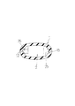
- FIG. 2 The AA cross section part of FIG. 2 is shown. It is an assembly
- the present embodiment forms a handle portion, which has a hollow shape and is integrally formed of a predetermined plastic material.
- the main body 1 and a control device that is provided in the handle main body 1 and controls the opening / closing operation of the door, and an antenna that receives the control device operating radio wave are integrated (hereinafter referred to as this embodiment).
- this embodiment this is referred to as a controller).
- the handle body 1 is formed of a composite material of polycarbonate resin containing glass fiber and polyethylene terephthalate, or a composite material of polycarbonate resin and polybutylene terephthalate. It is what has become.
- the handle body 1 has a hollow integrated shape having openings communicating with both ends thereof, and the shape in the longitudinal direction is formed by a part of an arc having a predetermined curvature. It is what.
- the handle body 1 is provided with a guide portion 12 for holding the controller 2 and having a concave groove shape (see FIGS. 2 and 3). ).
- a guide part 12 has a shape in the longitudinal direction of the same arc shape as the shape of the handle body 1 itself, as shown in FIGS. 3 to 5, for example.
- the guide portion 12 has a concentric shape with respect to the shape of the arc formed by the handle body 1.
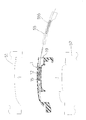
- the guide portion 12 provided in the handle main body 1 can be formed integrally with the middle die 55 (see FIG. 5) for forming the internal structure of the handle main body 1, and You will be able to do it at the same time. That is, as shown in FIG. 5, for example, a mold portion 555 for forming the guide portion 12 is integrally provided in a part of the middle die 55 for forming the handle main body 1, and such an intermediate die 55 is formed. By performing the pulling operation along the circumferential direction of the arc forming the handle body 1, the guide portion 12 can be formed simultaneously with the formation of the inside of the handle body 1. Further, a stopper portion 15 is provided at the guide portion 12 having such a configuration, for example, as shown in FIG. 4 or FIG. Then, by engaging the projecting engaging portion 25 formed in a part of the controller 2 at the stopper portion 15, the positioning of the controller 2 in the handle main body 1 is reliably performed. It will be.
- the controller 2 installed in the guide portion 12 has a cubic shape or a strip shape, and has one end side.
- An end portion 29 having a predetermined plane portion is formed in the.
- at least one pair of engaging portions 25 each having a protruding shape is provided at the side surface portion of the strip-shaped controller 2 so as to form a bilaterally symmetric shape in a plan view. (See FIGS. 1 and 2).
- such an engaging portion 25 engages with the groove-shaped guide portion 12 formed in the handle main body 1 so that the entire controller 2 is held in the handle main body 1. It is like that.
- Such a protruding engagement portion 25 is formed with the guide portion 12 and the stopper portion 15 (FIG.
- a cable 23 is provided on the other end side of the controller 2, and a terminal 21 is provided at the tip of the cable 23.
- the power supply to the controller 2 and the transmission of the signal received by the controller 2 to the transmitting / receiving device are performed via the terminal 21 and the cable 23.
- a switch mechanism 6 is provided at the end portion 29 of the controller 2.
- a cap 3 formed so as to close one open end of the handle body 1 is attached to one side surface of the switch mechanism 6.
- the cap 3 is formed in a lid portion 31 formed so as to close the one opening end portion, an attachment leg portion 32 that forms an attachment portion to the handle body 1, and a lower portion of the attachment leg portion 32. And a base portion 33.
- the handle body 1 itself can be reduced in weight while ensuring a certain degree of rigidity.
- the guide portion 12 for mounting the controller 2 and the integrated controller 2 such as an antenna into the handle body 1 can be formed simultaneously with the molding of the hollow handle body 1.
- the controller 2 is inserted into the handle main body 1 formed in this way, and the protruding shape formed in the controller 2 is formed at the groove-shaped guide portion 12 formed in the handle main body 1.
- the longitudinal direction of the guide portion 12 formed in the handle body 1 is formed in the same arc shape as the shape of the handle body 1 itself.
- the guide portion 12 formed in the handle body 1 is formed as shown in FIG.
- the middle mold 55 for forming the internal structure of the handle main body 1 can be made integrally and simultaneously. That is, a mold portion 555 for forming the groove-shaped guide portion 12 is integrally provided on a part of the middle die 55 for molding the handle main body 1, and such an operation for pulling out the middle die 55 is performed.
- the guide portion 12 can be formed simultaneously with the formation of the inside of the handle body by causing the handle body 1 to be formed along the circumferential direction of the arc forming the handle body 1.
- a stopper 15 for holding the controller 2 at a predetermined position in the handle body 1 is provided at the guide portion 12 as shown in FIG. 3 or FIG. 5, for example. ing.
- an engaging portion 25 (see FIGS. 1 and 3) formed in a part of the controller 2 at the stopper portion 15, the positioning of the controller 2 in the handle body 1 is reliably performed. Will come to be.
- the radio wave receiving direction position of the controller 2 is set on the handle body 1.
- An appropriate position can be set with respect to the outer surface, and the reception function of the controller 2 can be maintained in an appropriate state.
- Such a controller 2 basically has a cubic shape, and at least a pair of outer peripheral portions are symmetrical with respect to the longitudinal direction in plan view.
- the engaging portion 25 is provided. Therefore, the mounting operation of the controller 2 in the handle main body 1 is performed through the engaging portion 25. Specifically, first, as shown in FIG. 4A, a terminal 21 provided on one end side of the controller 2 is made to face one opening 19 of the handle body 1. Then, next, for example, as shown in FIGS. 4B and 4C, the engaging portion 25 formed on the outer peripheral portion of the controller 2 is engaged with the guide portion 12 formed in the handle body 1. In the combined state, the controller 2 is sequentially pushed into the handle body 1. As a result, the controller 2 is accommodated in a predetermined position in the handle body 1.
- the engaging portion 25 formed on the side surface portion of the controller 2 is engaged with the stopper portion 15 formed in the handle body 1 as shown in FIGS.
- the controller 2 is reliably positioned in the longitudinal direction in the handle body 1. In this way, the mounting operation of the controller 2 in the handle main body 1 is performed efficiently.
- the controller 2 is housed in a predetermined case in a state where the control device, the antenna, and the like are gathered together, and an end portion 29 formed of a predetermined flat portion on one end side of the case.
- the tip of the mounting leg 32 of the cap 3 for sealing the opening 19 formed on one end surface in the longitudinal direction of the handle main body 1 is formed at such an end 29. It is also conceivable to make them abut.
- the cap 3 is attached to the opening 19 formed on one end surface side of the handle main body 1, whereby the handle of the controller 2 is Attachment to a predetermined position in the main body 1 is surely performed. That is, the positioning of the controller 2 in the handle main body 1 is reliably performed.
- the upper mold 51, the lower mold 52, and the middle mold 55 are set in a predetermined state.
- a predetermined thermoplastic synthetic resin material such as a polycarbonate resin material containing glass fibers
- the mold opening operation (process) of each mold is performed.
- the mold opening process first, the molds are opened by moving the upper and lower molds 51 and 52 in the vertical direction.
- a mold opening (die cutting) operation of the middle mold 55 having an arc shape with respect to the longitudinal direction is performed. As shown in FIG.
- the die-cutting operation of the intermediate die 55 is performed along the circumferential line of the arc formed by the longitudinal center line of the molded product (work) that forms the handle body 1.
- the guide portion 12 and the stopper portion 15 formed in the handle body 1 are formed simultaneously with the formation of the inner diameter side of the handle body 1.
- the drawing operation of the middle die 55 is smoothly performed.
Abstract
[Problem] To form a plastic handle body so as to be hollow using a mold, and to fit a controller in the handle body. [Solution] This invention comprises: a handle body (1) having a hollow configuration, the entire handle body being formed integrally from a predetermined plastic material; and a controller (2) provided in the handle body (1), the controller comprising an antenna, a control device for controlling the opening/closing or other actions of the door, and other elements that are integrally provided. The handle body (1) has a hollow integral configuration in which an opening is present at both ends, and is formed so that the configuration of the handle body in the longitudinal direction is a part of an arc having a predetermined curvature. A groove-shaped guide section (12) for holding the controller (2) is provided in the handle body (1). The guide section (12) is provided so as to have the same arc-shaped configuration in the longitudinal direction as the shape of the handle body (1), i.e., a configuration that is concentric with respect to the arc shape formed by the handle body (1).
Description
本発明はドアハンドル装置に関するものであり、特に、レバー状のハンドル本体が所定のプラスチック材にて形成されるものであって中空状の一体方式のものからなるようにするとともに、このような中空状ハンドル本体の、その外周部の肉厚を必要な部分は厚肉状に形成させ、そこのところに、内部に装着される制御装置(コントローラ)等を取付けるためのビスネジ用台座(ボス部)を形成させるようにしたドアハンドル装置に関するものである。
The present invention relates to a door handle device, and in particular, a lever-like handle body is made of a predetermined plastic material and is made of a hollow integrated system, and such a hollow Screw-shaped base (boss) for attaching the controller (controller), etc. mounted inside to the part where the thickness of the outer peripheral part of the handle body is required to be thick. The present invention relates to a door handle device that is formed.
従来のドアハンドル装置としては、例えば特開2000-179192号公報記載のものの如く、ハンドル本体と、当該ハンドル本体をドア外板面に保持する役目を果たすベースと、からなる二分割式構造のものであって、これらが、いずれもプラスチック材てに形成されるようになっているものが挙げられる。そして、このような構成からなるものにおいて、上記ハンドル本体内に所定の制御装置等を装着した後に、その裏側からカバーを形成するベースを所定のビスネジ等を用いて取付けてドアハンドル装置を形成させるようにしたものがある。また、上記ハンドル本体とカバーとをガスインジェクション成形手段等を用いて中空一体形状に形成させ、このような中空一体形状のハンドル本体を基礎に、ドアハンドル装置を形成させるようにしたものも挙げられる。
As a conventional door handle device, for example, as described in Japanese Patent Application Laid-Open No. 2000-179192, a two-part structure having a handle body and a base that serves to hold the handle body on the door outer plate surface However, there are those which are all formed as plastic materials. And in what consists of such a structure, after mounting a predetermined control apparatus etc. in the said handle body, the base which forms a cover from the back side is attached using a predetermined screw etc., and a door handle apparatus is formed. There is something like that. In addition, the handle main body and the cover may be formed into a hollow integrated shape using a gas injection molding means or the like, and a door handle device may be formed based on the hollow integrated handle main body. .
ところで、上記二分割式構造のものにおいては、ハンドル本体がアウタ部材とインナ部材との二つの部材からなるものであるため、部品点数が増え、部品管理上煩雑にならざるを得ないと言う問題点がある。また、上記ガスインジェクション方式にて中空一体形状に形成させるようにしたものにおいては、その外周部の肉厚が均等な状態に形成されることとなり、ボス部形成のための厚肉部等を得ることが難しいと言う問題点がある。このような問題点を解決するために、ハンドル本体を、所定の金型等を用いて中空状の一体形状に形成させるとともに、その内部には制御装置取付用の取付部等をも形成させるようにしたドアハンドル装置を提供しようとするのが、本発明の目的(課題)である。
By the way, in the above-mentioned two-part structure, the handle main body is composed of two members, an outer member and an inner member, so that the number of parts increases and the parts management must be complicated. There is a point. Moreover, in what was formed in the hollow integrated shape by the said gas injection system, the thickness of the outer peripheral part will be formed in a uniform state, and the thick part for boss part formation, etc. will be obtained. There is a problem that it is difficult. In order to solve such a problem, the handle main body is formed into a hollow integrated shape using a predetermined mold or the like, and a mounting portion for mounting the control device is also formed therein. An object (problem) of the present invention is to provide a door handle device.
上記課題を解決するために、本発明においては次のような手段を講ずることとした。すなわち、請求項1記載の発明である第一の発明においては、取手部を形成するものであって中空一体形状の形態からなるハンドル本体と、当該ハンドル本体内に設けられるものであってドアの開閉作動等を制御する制御装置並びに当該制御装置作動用電波の受信等を担うアンテナ等を内蔵するドアハンドル装置に関して、上記ハンドル本体を、所定のプラスチック材にて中空一体形状に、かつ、全体が所定の曲率を有する円弧の一部にて形成させるようにするとともに、このようなハンドル本体の内部に上記制御装置及びアンテナを保持するためのものであって凹溝状の形態からなるガイド部を設けるようにし、一方、上記制御装置及びアンテナを一体的に形成させるとともに、これら制御装置及びアンテナの一体化されたものの、その外周部に複数の凸起状形態からなる係合部を設けるようにし、このように形成された係合部を上記凹溝状形態からなるガイド部のところに係合させることによって本制御装置及びアンテナを上記ハンドル本体内に収容するようにした構成を採ることとした。
In order to solve the above-mentioned problems, the following measures are taken in the present invention. That is, in the first invention which is the invention described in claim 1, a handle main body which forms a handle portion and has a hollow integrated shape, and is provided in the handle main body, and is provided in the door main body. With respect to a door handle device that incorporates a control device that controls the opening / closing operation and the like, and an antenna that is responsible for receiving the control device operating radio waves, etc., the handle body is made into a hollow integrated shape with a predetermined plastic material, and the whole A guide portion that is formed in a part of an arc having a predetermined curvature and that holds the control device and the antenna inside the handle body and has a concave groove shape. On the other hand, the control device and the antenna are integrally formed, and the control device and the antenna are integrated, The control device and the antenna are provided by providing a plurality of protruding portions with engaging portions and engaging the engaging portions formed in this manner with the guide portions having the recessed groove shape. Is configured to be accommodated in the handle body.
次に、請求項2記載の発明である第二の発明においては、上記第一の発明と同様、請求項1記載の制御装置並びに当該制御装置作動用電波の受信等を担うアンテナを内蔵するドアハンドル装置に関して、上記ガイド部の、その長手方向の形態を、上記ハンドル本体の形成する円弧と同心円状の形態からなる円弧にて形成させるようにした構成を採ることとした。
Next, in the second invention as claimed in claim 2, as in the first invention, the door incorporating the control device according to claim 1 and the antenna for receiving the control device operating radio wave, etc. With respect to the handle device, the configuration in which the guide portion in the longitudinal direction is formed by an arc concentric with the arc formed by the handle body is adopted.
次に、請求項3記載の発明である第三の発明においては、上記第一の発明と同様、請求項1または請求項2記載の制御装置並びに当該制御装置作動用電波の受信等を担うアンテナを内蔵するドアハンドル装置に関して、上記ガイド部内に、上記制御装置及びアンテナの一体化されたものの、その外周部に形成された係合部を所定の位置に固定するためのストッパ部を設けるようにした構成を採ることとした。
Next, in the third invention as claimed in claim 3, as in the first invention, the control device according to claim 1 or claim 2 and the antenna responsible for receiving the control device operating radio wave, etc. As for the door handle device with a built-in door, a stopper portion is provided in the guide portion for fixing the engaging portion formed on the outer periphery of the control device and the antenna in a predetermined position. It was decided to adopt the configuration.
次に、請求項4記載の発明である第四の発明においては、上記第一の発明と同様、請求項1ないし請求項3記載の制御装置並びに当該制御装置作動用電波の受信等を担うアンテナを内蔵するドアハンドル装置に関して、上記制御装置及びアンテナの一体化されたものを立方体形状の形態からなるようにするとともに、その外周部に形成される係合部を、平面視において、長手方向に対して左右対象形を成すように少なくとも一対以上設けるようにした構成を採ることとした。
Next, in the fourth invention which is the invention described in claim 4, as in the case of the first invention, the control apparatus according to claims 1 to 3 and an antenna responsible for receiving the radio waves for operating the control apparatus, etc. As for the door handle device incorporating the above-mentioned, the integrated control device and antenna are formed in a cubic shape, and the engaging portion formed on the outer peripheral portion thereof is arranged in the longitudinal direction in plan view. On the other hand, at least one pair is provided so as to form a right and left target shape.
次に、請求項5記載の発明である第五の発明においては、上記第一の発明と同様、請求項4記載の制御装置並びに当該制御装置作動用電波の受信等を担うアンテナを内蔵するドアハンドル装置に関して、上記制御装置及びアンテナの一体化されたものを所定のケース内に収容するとともに、当該ケースの一方の端部側に所定の平面部を有するエンド部を設けるようにし、このエンド部のところに本ハンドル本体の一方の端面側に取付けられるキャップの取付用脚部の先端部を当接させるようにした構成を採ることとした。
Next, in a fifth aspect of the invention according to the fifth aspect, as in the first aspect, a door incorporating the control device according to the fourth aspect and an antenna for receiving the control device operating radio wave and the like. As for the handle device, the integrated control device and antenna are accommodated in a predetermined case, and an end portion having a predetermined flat surface portion is provided on one end side of the case. However, a configuration is adopted in which the tip end portion of the mounting leg portion of the cap attached to one end face side of the handle main body is brought into contact.
請求項1記載の発明である第一の発明について説明する。本発明によれば、上記構成を採ることにより、ハンドル本体自体を、ある程度の剛性を確保したうえで、その軽量化を図ることができるようになる。また、制御装置及びアンテナ等の一体化されたコントローラのハンドル本体内部への装着用ガイド部も、上記中空状ハンドル本体の成形と同時に、かつ、一体的に形成させることができるようになり、本ハンドル本体の成形加工の効率化を図ることができるようになる。そして、このように形成されたハンドル本体内へ上記コントローラを挿入するとともに、上記ハンドル本体内に形成された凹溝状のガイド部のところに上記コントローラに形成された凸起状の係合部を係合させることによって、本コントローラの上記ハンドル本体内への装着及びその固定が、円滑に、かつ、確実に行われることとなる。
The first invention as claimed in claim 1 will be described. According to the present invention, by adopting the above configuration, it is possible to reduce the weight of the handle body itself while ensuring a certain degree of rigidity. In addition, a guide part for mounting the controller and the integrated controller such as an antenna inside the handle body can be formed integrally with the hollow handle body. It becomes possible to improve the efficiency of the molding process of the handle body. Then, the controller is inserted into the handle body formed in this way, and a protruding engagement portion formed on the controller is provided at the groove-shaped guide portion formed in the handle body. By engaging, the mounting of the controller in the handle body and the fixing thereof are smoothly and reliably performed.
次に、請求項2記載の発明である第二の発明について説明する。このものも、その基本的な点は上記請求項1記載の発明である第一の発明のものと同じである。具体的には、本発明のものにおいては、上記ハンドル本体内に形成されるガイド部の、その長手方向の形態を、本ハンドル本体自体の形状と同じ円弧状の形態からなるようにするとともに、その円弧の形態を同心円状の形態からなるようにしたので、本ハンドル本体内に形成されるガイド部の形成を、本ハンドル本体の内部構造形成のための中型にて、一体的に、かつ、同時に行わせることができるようになる。すなわち、本ハンドル本体成形のための中型の一部に、上記凹溝状のガイド部を形成させるための型部を一体的に設けておくとともに、このような中型の引抜き操作を上記ハンドル本体を形成する円弧の円周方向に沿って行わせることによって、ハンドル本体内部の形成と同時に上記ガイド部の形成を行なわせることができるようになる。
Next, a second invention which is the invention according to claim 2 will be described. The basic point of this is also the same as that of the first aspect of the invention described in claim 1 above. Specifically, in the present invention, the shape of the guide portion formed in the handle main body in the longitudinal direction is the same arc shape as the shape of the handle main body itself, Since the shape of the arc is a concentric shape, the guide portion formed in the handle main body is formed integrally with the middle mold for forming the internal structure of the handle main body, and You will be able to do it at the same time. That is, a part of the middle mold for forming the handle body is integrally provided with a mold part for forming the concave groove-shaped guide part. By performing along the circumferential direction of the arc to be formed, the guide portion can be formed simultaneously with the formation of the inside of the handle body.
次に、請求項3記載の発明である第三の発明について説明する。このものも、その基本的な点は上記請求項1または請求項2記載の発明である第一の発明または第二の発明のものと同じである。具体的には、本発明のものにおいては、上記制御装置及びアンテナ等の一体化されたコントローラを、上記ハンドル本体内の所定の位置に保持するためのストッパ部が上記ガイド部のところに設けられるようになっていることより、このストッパ部のところに上記コントローラの一部に形成された係合部を係合させることによって、本コントローラのハンドル本体内における位置決めを確実に行わせることができるようになる。
Next, a third invention which is the invention described in claim 3 will be described. The basic point of this is also the same as that of the first invention or the second invention which is the invention described in claim 1 or claim 2. Specifically, in the present invention, a stopper portion for holding the integrated controller such as the control device and the antenna at a predetermined position in the handle body is provided at the guide portion. Thus, the controller can be surely positioned in the handle body by engaging the engaging portion formed in a part of the controller with the stopper portion. become.
次に、請求項4記載の発明である第四の発明について説明する。このものも、基本的には上記請求項1ないし請求項3記載の発明である第一の発明ないし第三の発明のものと同じである。これらに加えて、本発明のものにおいては、上記コントローラを立方体形状の形態からなるようにするとともに、その外周部のところに、平面視において長手方向に対して左右対称形をなすように少なくとも一対以上の係合部を設けるようにしたので、このようなコントローラのハンドル本体内への装着作業が、上記係合部を介して円滑に行なわれることとなる。具体的には、まず、立方体形状の形態からなるコントローラを、まず、ハンドル本体の一方の端部側に形成された開口部のところに臨ませる。そして、このような状態において、上記コントローラの外周部に形成された係合部をハンドル本体内に形成されたガイド部のところに係合させるとともに、このような状態において、コントローラを順次ハンドル本体内へと押し込むようにする。これによって、上記コントローラはハンドル本体内の所定の位置に収容されることとなる。このようにして、コントローラのハンドル本体内への設置が手際良く行われることとなる。
Next, a fourth invention which is the invention described in claim 4 will be described. This is basically the same as that of the first to third inventions according to the first to third aspects of the invention. In addition to these, in the present invention, the controller is formed in a cubic shape, and at least one pair is formed at the outer peripheral portion so as to be symmetrical with respect to the longitudinal direction in plan view. Since the above engaging portion is provided, the mounting operation of the controller in the handle main body is smoothly performed via the engaging portion. Specifically, first, a controller having a cubic shape is first exposed to an opening formed on one end side of the handle body. In such a state, the engaging portion formed on the outer peripheral portion of the controller is engaged with the guide portion formed in the handle body, and in this state, the controller is sequentially moved into the handle body. To push into. Thus, the controller is accommodated at a predetermined position in the handle body. In this way, the controller can be installed in the handle main body.
次に、請求項5記載の発明である第五の発明について説明する。このものも、基本的には上記請求項4記載の発明である第四の発明のものと同じである。これらに加えて、本発明のものにおいては、上記制御装置及びアンテナ等の一体化されたコントローラを所定のケース内に収容するとともに、このようなケースの一方の端部側に所定の平面部からなるエンド部を形成させ、このようなエンド部のところにハンドル本体の長手方向の一方の端面部を封止するためのキャップの、その脚部先端を当接させるようにしたので、ハンドル本体内に上記コントローラが挿入された後、上記キャップをハンドル本体の端面側に装着することによって、上記コントローラの上記ハンドル本体内における所定の位置への装着が確実に行われることとなる。すなわち、コントローラのハンドル本体内における位置決めが確実に行われることとなる。
Next, a fifth invention which is the invention of claim 5 will be described. This is basically the same as that of the fourth invention which is the invention of claim 4. In addition to these, in the present invention, an integrated controller such as the control device and the antenna is accommodated in a predetermined case, and from one predetermined end portion of the case to a predetermined plane portion. Since the end of the leg of the cap for sealing one end surface in the longitudinal direction of the handle body is brought into contact with such an end, After the controller is inserted, the cap is attached to the end face side of the handle main body, so that the controller is reliably attached to a predetermined position in the handle main body. That is, the positioning of the controller in the handle body is reliably performed.
本発明を実施するための形態について、図1ないし図5を基に説明する。本実施の形態にかかるものは、図1または図2に示す如く、取手部を形成するものであって、中空状の形態からなるとともに全体が所定のプラスチック材にて一体的に形成されるハンドル本体1と、当該ハンドル本体1内に設けられるものであってドアの開閉作動等を制御する制御装置並びに当該制御装置作動用電波の受信等を担うアンテナ等の一体化されたもの(以下本実施の形態においては、これをコントローラと言う)2と、からなることを基本とするものである。このような基本構成からなるものにおいて、上記ハンドル本体1は、グラスファイバー入りのポリカーボネート樹脂とポリエチレンテレフタレートとの複合材か、または、上記ポリカーボネート樹脂とポリブチレンテレフタレートとの複合材にて形成されるようになっているものである。また、本ハンドル本体1は、その両端部に連通した開口部を有する中空一体状の形態からなるとともに、その長手方向の形態が所定の曲率を有する円弧の一部にて形成されるようになっているものである。そして、このようなハンドル本体1の内部には、上記コントローラ2を保持するためのものであって凹溝状の形態からなるガイド部12が設けられるようになっている(図2,図3参照)。なお、このようなガイド部12は、その長手方向の形態が、例えば図3ないし図5に示す如く、ハンドル本体1自体の形状と同じ円弧状の形態を有するようになっているものである。具体的には、上記ガイド部12は、上記ハンドル本体1の形成する円弧の形状に対して同心円状の形態を有するようになっているものである。
Embodiments for carrying out the present invention will be described with reference to FIGS. As shown in FIG. 1 or FIG. 2, the present embodiment forms a handle portion, which has a hollow shape and is integrally formed of a predetermined plastic material. The main body 1 and a control device that is provided in the handle main body 1 and controls the opening / closing operation of the door, and an antenna that receives the control device operating radio wave are integrated (hereinafter referred to as this embodiment). In this form, this is referred to as a controller). In such a basic structure, the handle body 1 is formed of a composite material of polycarbonate resin containing glass fiber and polyethylene terephthalate, or a composite material of polycarbonate resin and polybutylene terephthalate. It is what has become. In addition, the handle body 1 has a hollow integrated shape having openings communicating with both ends thereof, and the shape in the longitudinal direction is formed by a part of an arc having a predetermined curvature. It is what. The handle body 1 is provided with a guide portion 12 for holding the controller 2 and having a concave groove shape (see FIGS. 2 and 3). ). In addition, such a guide part 12 has a shape in the longitudinal direction of the same arc shape as the shape of the handle body 1 itself, as shown in FIGS. 3 to 5, for example. Specifically, the guide portion 12 has a concentric shape with respect to the shape of the arc formed by the handle body 1.
このような構成を採ることによって、ハンドル本体1内に設けられるガイド部12の形成を、本ハンドル本体1の内部構造形成のための中型55(図5参照)にて、一体的に、かつ、同時に行わせることができるようになる。すなわち、本ハンドル本体1成形のための中型55の一部に、例えば図5に示す如く、上記ガイド部12を形成させるための型部555を一体的に設けておくとともに、このような中型55の引抜き操作を上記ハンドル本体1を形成する円弧の円周方向に沿って行わせることによって、ハンドル本体1内部の形成と同時に、上記ガイド部12の形成を行なわせることができるようになる。また、このような構成からなる上記ガイド部12のところには、例えば図4または図5に示す如く、ストッパ部15が設けられるようになっている。そして、このストッパ部15のところに、上記コントローラ2の一部に形成された凸起状の係合部25を係合させることによって、本コントローラ2のハンドル本体1内における位置決めが確実に行われることとなる。
By adopting such a configuration, the guide portion 12 provided in the handle main body 1 can be formed integrally with the middle die 55 (see FIG. 5) for forming the internal structure of the handle main body 1, and You will be able to do it at the same time. That is, as shown in FIG. 5, for example, a mold portion 555 for forming the guide portion 12 is integrally provided in a part of the middle die 55 for forming the handle main body 1, and such an intermediate die 55 is formed. By performing the pulling operation along the circumferential direction of the arc forming the handle body 1, the guide portion 12 can be formed simultaneously with the formation of the inside of the handle body 1. Further, a stopper portion 15 is provided at the guide portion 12 having such a configuration, for example, as shown in FIG. 4 or FIG. Then, by engaging the projecting engaging portion 25 formed in a part of the controller 2 at the stopper portion 15, the positioning of the controller 2 in the handle main body 1 is reliably performed. It will be.
次に、このようなガイド部12内に設置されるコントローラ2は、図1または図2に示す如く、その外観形態は立方体形状あるいは短冊状の形態からなるものであり、その一方の端部側には所定の平面部を有するエンド部29が形成されるようになっている。そして、このような短冊状コントローラ2の、その側面部のところには凸起状の形態からなる係合部25が、その平面視において左右対称形を成すように少なくとも一対以上設けられるようになっている(図1、図2参照)。そして更に、このような係合部25は、上記ハンドル本体1内に形成された凹溝状のガイド部12のところに係合して、コントローラ2全体のハンドル本体1内における保持が成されるようになっている。このような凸起状の係合部25は、本コントローラ2がハンドル本体1内に挿入(装着)された状態において、上記ハンドル本体1内に形成されたガイド部12及びストッパ部15(図3参照)のところに係合して、コントローラ2全体の位置決めを担うようになっているものである。なお、上記コントローラ2に関しては、上記制御装置及びアンテナを所定のケース内に収納して一体化するとともに、このようなケースの外側に凸起状の係合部25を設けるようにしたものも考えられる。
Next, as shown in FIG. 1 or FIG. 2, the controller 2 installed in the guide portion 12 has a cubic shape or a strip shape, and has one end side. An end portion 29 having a predetermined plane portion is formed in the. Further, at least one pair of engaging portions 25 each having a protruding shape is provided at the side surface portion of the strip-shaped controller 2 so as to form a bilaterally symmetric shape in a plan view. (See FIGS. 1 and 2). Further, such an engaging portion 25 engages with the groove-shaped guide portion 12 formed in the handle main body 1 so that the entire controller 2 is held in the handle main body 1. It is like that. Such a protruding engagement portion 25 is formed with the guide portion 12 and the stopper portion 15 (FIG. 3) formed in the handle body 1 in a state where the controller 2 is inserted (mounted) in the handle body 1. (See)) and is responsible for positioning the controller 2 as a whole. Regarding the controller 2, the control device and the antenna are housed and integrated in a predetermined case, and a protruding engagement portion 25 is provided outside the case. It is done.
このようなコントローラ2のもう一方の端部側には、例えば図1または図2に示す如く、ケーブル23が設けられるとともに、その先端部のところには端子21が設けられるようになっている。このような端子21及びケーブル23を介して上記コントローラ2への電力供給並びに上記コントローラ2にて受信した信号の受発信装置への送信等が行われるようになっているものである。また、このようなコントローラ2のエンド部29のところにはスイッチ機構6が設けられるようになっている。そして、このスイッチ機構6の一方の側面部のところには、上記ハンドル本体1の一方の開口端部を塞ぐように形成されたキャップ3が取付けられるようになっている。このキャップ3は、上記一方の開口端部を塞ぐように形成された蓋部31と、ハンドル本体1への取付部を成す取付用脚部32と、当該取付用脚部32の下方部に形成されるベース部33と、からなるものである。そして、このようなキャップ3の、その取付用脚部32の先端部のところが、上記コントローラ2のエンド部29に当接して上記コントローラ2の、ハンドル本体1内における、その長手方向の位置決めが成されるようになっているものである(図2参照)。そして更に、このようなベース部33は、本キャップ3がハンドル本体1に取付けられた状態において、上記取付用脚部32とともに、上記スイッチ機構6をハンドル本体1の端末部のところに保持するようになっているものである。
For example, as shown in FIG. 1 or 2, a cable 23 is provided on the other end side of the controller 2, and a terminal 21 is provided at the tip of the cable 23. The power supply to the controller 2 and the transmission of the signal received by the controller 2 to the transmitting / receiving device are performed via the terminal 21 and the cable 23. Further, a switch mechanism 6 is provided at the end portion 29 of the controller 2. A cap 3 formed so as to close one open end of the handle body 1 is attached to one side surface of the switch mechanism 6. The cap 3 is formed in a lid portion 31 formed so as to close the one opening end portion, an attachment leg portion 32 that forms an attachment portion to the handle body 1, and a lower portion of the attachment leg portion 32. And a base portion 33. Then, the tip of the mounting leg 32 of the cap 3 contacts the end 29 of the controller 2 to position the controller 2 in the handle body 1 in the longitudinal direction. (See FIG. 2). Further, such a base portion 33 holds the switch mechanism 6 at the terminal portion of the handle body 1 together with the mounting leg portion 32 in a state where the cap 3 is attached to the handle body 1. It is what has become.
このような構成を採ることにより、本実施の形態のものにおいては、ハンドル本体1自体を、ある程度の剛性を確保したうえで、その軽量化を図ることができるようになる。また、制御装置及びアンテナ等の一体化されたコントローラ2のハンドル本体1内への装着用ガイド部12を、上記中空状ハンドル本体1の成形と同時に、かつ、一体的に形成させることができるようになり、本ハンドル本体1の成形加工の効率化を図ることができるようになる(図3及び図5参照)。そして、このように形成されたハンドル本体1内へ上記コントローラ2を挿入するとともに、上記ハンドル本体1内に形成された凹溝状のガイド部12のところに上記コントローラ2に形成された凸起状の係合部25を係合させることによって、本コントローラ2の上記ハンドル本体1内への装着、及び、その固定が、確実に、かつ、円滑に行われることとなる(図4参照)。
By adopting such a configuration, in the present embodiment, the handle body 1 itself can be reduced in weight while ensuring a certain degree of rigidity. Further, the guide portion 12 for mounting the controller 2 and the integrated controller 2 such as an antenna into the handle body 1 can be formed simultaneously with the molding of the hollow handle body 1. Thus, it is possible to increase the efficiency of the molding process of the handle body 1 (see FIGS. 3 and 5). Then, the controller 2 is inserted into the handle main body 1 formed in this way, and the protruding shape formed in the controller 2 is formed at the groove-shaped guide portion 12 formed in the handle main body 1. By engaging the engaging portion 25, the mounting of the controller 2 in the handle main body 1 and the fixing thereof are surely and smoothly performed (see FIG. 4).
また、本実施の形態のものにおいては、上記ハンドル本体1内に形成されるガイド部12の、その長手方向の形態を、本ハンドル本体1自体の形状と同じ円弧状の形態からなるようにするとともに、その円弧の形態をハンドル本体1を形成する円弧と同心円状の形態からなるようにしたので、本ハンドル本体1内に形成されるガイド部12の形成を、例えば図5に示す如く、本ハンドル本体1の内部構造形成のための中型55にて、一体的に、かつ、同時に行わせることができるようになる。すなわち、本ハンドル本体1成形のための中型55の一部に、上記凹溝状のガイド部12を形成させるための型部555を一体的に設けておくとともに、このような中型55の引抜き操作を上記ハンドル本体1を形成する円弧の円周方向に沿って行わせることによって、ハンドル本体内部の形成と同時に上記ガイド部12の形成をも行なわせることができるようになる。
Further, in the present embodiment, the longitudinal direction of the guide portion 12 formed in the handle body 1 is formed in the same arc shape as the shape of the handle body 1 itself. In addition, since the shape of the arc is concentric with the arc forming the handle body 1, the guide portion 12 formed in the handle body 1 is formed as shown in FIG. The middle mold 55 for forming the internal structure of the handle main body 1 can be made integrally and simultaneously. That is, a mold portion 555 for forming the groove-shaped guide portion 12 is integrally provided on a part of the middle die 55 for molding the handle main body 1, and such an operation for pulling out the middle die 55 is performed. The guide portion 12 can be formed simultaneously with the formation of the inside of the handle body by causing the handle body 1 to be formed along the circumferential direction of the arc forming the handle body 1.
なお、このようなガイド部12のところには、例えば図3または図5に示す如く、上記コントローラ2を上記ハンドル本体1内の所定の位置に保持するためのストッパ部15が設けられるようになっている。このストッパ部15のところに上記コントローラ2の一部に形成された係合部25(図1,図3参照)を係合させることによって、本コントローラ2のハンドル本体1内における位置決めが確実に行われるようになる。また、このような構成を採るものにおいて、上記ハンドル本体1の外表面側の肉厚を均一な状態で、かつ、適宜値に設定することによって、コントローラ2の電波受信方向位置をハンドル本体1の外表面に対して適切な位置に設定することができるようになり、コントローラ2の受信機能を適切な状態に保持することができるようになる。
Note that a stopper 15 for holding the controller 2 at a predetermined position in the handle body 1 is provided at the guide portion 12 as shown in FIG. 3 or FIG. 5, for example. ing. By engaging an engaging portion 25 (see FIGS. 1 and 3) formed in a part of the controller 2 at the stopper portion 15, the positioning of the controller 2 in the handle body 1 is reliably performed. Will come to be. Further, in such a configuration, by setting the thickness of the outer surface side of the handle body 1 in a uniform state and an appropriate value, the radio wave receiving direction position of the controller 2 is set on the handle body 1. An appropriate position can be set with respect to the outer surface, and the reception function of the controller 2 can be maintained in an appropriate state.
なお、このようなコントローラ2は、基本的には立方体形状の形態からなるものであるとともに、その外周部のところには、平面視において長手方向に対して左右対称形をなすように少なくとも一対以上の係合部25が設けられるようになっている。従って、このようなコントローラ2のハンドル本体1内への装着作業は、上記係合部25を介して行なわれることとなる。具体的には、まず、図4の(イ)に示す如く、ハンドル本体1の一方の開口部19のところにコントローラ2の一方の端部側に設けられた端子21を臨ませる。そして、次に、例えば図4の(ロ)、(ハ)に示す如く、上記コントローラ2の外周部に形成された係合部25をハンドル本体1内に形成されたガイド部12のところに係合させた状態でコントローラ2を順次ハンドル本体1内へと押し込むようにする。これによって、上記コントローラ2はハンドル本体1内の所定の位置に収容されるようになる。そして、このような状態において、コントローラ2の側面部に形成された係合部25を、例えば図3、図4に示す如く、上記ハンドル本体1内に形成されたストッパ部15のところに係合させ、本コントローラ2のハンドル本体1内における長手方向位置決めを確実に行わせるようにする。このようにして、コントローラ2のハンドル本体1内への装着作業が手際良く行われることとなる。
Such a controller 2 basically has a cubic shape, and at least a pair of outer peripheral portions are symmetrical with respect to the longitudinal direction in plan view. The engaging portion 25 is provided. Therefore, the mounting operation of the controller 2 in the handle main body 1 is performed through the engaging portion 25. Specifically, first, as shown in FIG. 4A, a terminal 21 provided on one end side of the controller 2 is made to face one opening 19 of the handle body 1. Then, next, for example, as shown in FIGS. 4B and 4C, the engaging portion 25 formed on the outer peripheral portion of the controller 2 is engaged with the guide portion 12 formed in the handle body 1. In the combined state, the controller 2 is sequentially pushed into the handle body 1. As a result, the controller 2 is accommodated in a predetermined position in the handle body 1. In such a state, the engaging portion 25 formed on the side surface portion of the controller 2 is engaged with the stopper portion 15 formed in the handle body 1 as shown in FIGS. The controller 2 is reliably positioned in the longitudinal direction in the handle body 1. In this way, the mounting operation of the controller 2 in the handle main body 1 is performed efficiently.
なお、上記コントローラ2に関しては、上記制御装置及びアンテナ等を一まとめにした状態で所定のケース内に収容するとともに、このようなケースの一方の端部側に所定の平面部からなるエンド部29を形成させ、このようなエンド部29のところにハンドル本体1の長手方向の一方の端面部に形成される開口部19を封止するためのキャップ3の、その取付用脚部32の先端を当接させるようにすることも考えられる。これによって、ハンドル本体1内に上記コントローラ2が挿入された後、上記キャップ3をハンドル本体1の一方の端面側に形成された開口部19のところに装着することによって、上記コントローラ2の上記ハンドル本体1内における所定位置への取付けが確実に行われることとなる。すなわち、コントローラ2のハンドル本体1内における位置決めが確実に行われることとなる。
The controller 2 is housed in a predetermined case in a state where the control device, the antenna, and the like are gathered together, and an end portion 29 formed of a predetermined flat portion on one end side of the case. The tip of the mounting leg 32 of the cap 3 for sealing the opening 19 formed on one end surface in the longitudinal direction of the handle main body 1 is formed at such an end 29. It is also conceivable to make them abut. Thus, after the controller 2 is inserted into the handle main body 1, the cap 3 is attached to the opening 19 formed on one end surface side of the handle main body 1, whereby the handle of the controller 2 is Attachment to a predetermined position in the main body 1 is surely performed. That is, the positioning of the controller 2 in the handle main body 1 is reliably performed.
次に、このような構成からなる中空状ハンドル本体1の成形方法(工程)について、図5を基に説明する。まず、上型51、下型52、中型55を所定の状態にセットする。このような状態において、所定の熱可塑性合成樹脂材(グラスファイバー入りのポリカーボネート樹脂材等)を上記各金型にて形成される空間内へ注入する。その後、上記各型の型開き作業(工程)を行う。なお、この型開き工程においては、まず、上下の各型51、52を上下方向に移動させて型開きを行なう。次に、長手方向に対して円弧状の形態からなる中型55の型開き(型抜き)作業を行う。この中型55の型抜き作業は、図5に示す如く、ハンドル本体1を形成することとなる成形品(ワーク)の長手方向中心線の成す円弧の円周線に沿って行わせるようにする。これによって、ハンドル本体1内に形成されるガイド部12及びストッパ部15等の形成が、上記ハンドル本体1の内径側の形成と同時に行われることとなる。これによって、中型55の引抜き作業が円滑に行われることとなる。
Next, a method (process) for forming the hollow handle body 1 having such a configuration will be described with reference to FIG. First, the upper mold 51, the lower mold 52, and the middle mold 55 are set in a predetermined state. In such a state, a predetermined thermoplastic synthetic resin material (such as a polycarbonate resin material containing glass fibers) is injected into the space formed by each mold. Thereafter, the mold opening operation (process) of each mold is performed. In this mold opening process, first, the molds are opened by moving the upper and lower molds 51 and 52 in the vertical direction. Next, a mold opening (die cutting) operation of the middle mold 55 having an arc shape with respect to the longitudinal direction is performed. As shown in FIG. 5, the die-cutting operation of the intermediate die 55 is performed along the circumferential line of the arc formed by the longitudinal center line of the molded product (work) that forms the handle body 1. As a result, the guide portion 12 and the stopper portion 15 formed in the handle body 1 are formed simultaneously with the formation of the inner diameter side of the handle body 1. As a result, the drawing operation of the middle die 55 is smoothly performed.
1 ハンドル本体
12 ガイド部
15 ストッパ部
19 開口部
2 コントローラ
21 端子
23 ケーブル
25 係合部
29 エンド部
3 キャップ
31 蓋部
32 取付用脚部
33 ベース部
51 上型
52 下型
55 中型
555 型部
6 スイッチ機構
DESCRIPTION OF SYMBOLS 1Handle body 12 Guide part 15 Stopper part 19 Opening part 2 Controller 21 Terminal 23 Cable 25 Engagement part 29 End part 3 Cap 31 Lid part 32 Mounting leg part 33 Base part 51 Upper mold 52 Lower mold 55 Middle mold 555 Mold part 6 Switch mechanism
12 ガイド部
15 ストッパ部
19 開口部
2 コントローラ
21 端子
23 ケーブル
25 係合部
29 エンド部
3 キャップ
31 蓋部
32 取付用脚部
33 ベース部
51 上型
52 下型
55 中型
555 型部
6 スイッチ機構
DESCRIPTION OF SYMBOLS 1
Claims (5)
- 取手部を形成するものであって中空一体形状の形態からなるハンドル本体と、当該ハンドル本体内に設けられるものであってドアの開閉作動等を制御する制御装置並びに当該制御装置作動用電波の受信等を担うアンテナ等を内蔵するドアハンドル装置において、上記ハンドル本体を、所定のプラスチック材にて中空一体形状に、かつ、全体が所定の曲率を有する円弧の一部にて形成させるようにするとともに、このようなハンドル本体の内部に上記制御装置及びアンテナを保持するためのものであって凹溝状の形態からなるガイド部を設けるようにし、一方、上記制御装置及びアンテナを一体的に形成させるとともに、これら制御装置及びアンテナの一体化されたものの、その外周部に複数の凸起状形態からなる係合部を設けるようにし、このように形成された係合部を上記凹溝状形態からなるガイド部のところに係合させることによって本制御装置及びアンテナを上記ハンドル本体内に収容するようにした構成からなることを特徴とするドアハンドル装置。 A handle main body that forms a handle portion and has a hollow integrated shape, a control device that is provided in the handle main body and controls the opening and closing operation of the door, etc., and reception of radio waves for operating the control device In a door handle device incorporating an antenna or the like, the handle main body is formed in a hollow integrated shape with a predetermined plastic material and a part of an arc having a predetermined curvature as a whole. In addition, a guide portion having a concave groove shape is provided inside the handle body for holding the control device and the antenna, while the control device and the antenna are integrally formed. In addition, although these control device and antenna are integrated, the outer peripheral portion is provided with a plurality of protruding portions, The control device and the antenna are accommodated in the handle body by engaging the engaging portion formed as described above with the guide portion having the concave groove shape. Door handle device to do.
- 請求項1記載のドアハンドル装置において、上記ガイド部の、その長手方向の形態を、上記ハンドル本体の形成する円弧と同心円状の形態からなる円弧にて形成させるようにした構成からなることを特徴とするドアハンドル装置。 2. The door handle device according to claim 1, wherein the longitudinal direction of the guide portion is formed by an arc concentric with the arc formed by the handle body. And door handle device.
- 請求項1または請求項2記載のドアハンドル装置において、上記ガイド部内に、上記制御装置及びアンテナの一体化されたものの、その外周部に形成された係合部を所定の位置に固定するためのストッパ部を設けるようにした構成からなることを特徴とするドアハンドル装置。 The door handle device according to claim 1 or 2, wherein the control device and the antenna are integrated in the guide portion, and an engaging portion formed on an outer peripheral portion thereof is fixed at a predetermined position. A door handle device comprising a configuration in which a stopper portion is provided.
- 請求項1ないし請求項3記載のドアハンドル装置において、上記制御装置及びアンテナの一体化されたものを立方体形状の形態からなるようにするとともに、その外周部に形成される係合部を、平面視において、長手方向に対して左右対象形を成すように少なくとも一対以上設けるようにした構成からなることを特徴とするドアハンドル装置。 4. The door handle device according to claim 1, wherein the control device and the antenna are integrated into a cubic shape, and the engaging portion formed on the outer periphery of the door handle device is flat. A door handle device comprising a configuration in which at least one pair is provided so as to form a left and right target shape in the longitudinal direction when viewed.
- 請求項4記載のドアハンドル装置において、上記制御装置及びアンテナの一体化されたものを所定のケース内に収容するとともに、当該ケースの一方の端部側に所定の平面部を有するエンド部を設けるようにし、このエンド部のところに本ハンドル本体の一方の端面側に取付けられるキャップの取付用脚部の先端部を当接させるようにした構成からなることを特徴とするドアハンドル装置。
5. The door handle device according to claim 4, wherein the integrated control device and antenna are accommodated in a predetermined case, and an end portion having a predetermined flat surface portion is provided on one end side of the case. Thus, the door handle device is characterized in that the end portion of the mounting leg portion of the cap attached to one end face side of the handle main body is brought into contact with the end portion.
Priority Applications (2)
| Application Number | Priority Date | Filing Date | Title |
|---|---|---|---|
| PCT/JP2011/064354 WO2012176296A1 (en) | 2011-06-23 | 2011-06-23 | Door handle device |
| JP2012519810A JP5426767B2 (en) | 2011-06-23 | 2011-06-23 | Door handle device |
Applications Claiming Priority (1)
| Application Number | Priority Date | Filing Date | Title |
|---|---|---|---|
| PCT/JP2011/064354 WO2012176296A1 (en) | 2011-06-23 | 2011-06-23 | Door handle device |
Publications (1)
| Publication Number | Publication Date |
|---|---|
| WO2012176296A1 true WO2012176296A1 (en) | 2012-12-27 |
Family
ID=47422176
Family Applications (1)
| Application Number | Title | Priority Date | Filing Date |
|---|---|---|---|
| PCT/JP2011/064354 WO2012176296A1 (en) | 2011-06-23 | 2011-06-23 | Door handle device |
Country Status (2)
| Country | Link |
|---|---|
| JP (1) | JP5426767B2 (en) |
| WO (1) | WO2012176296A1 (en) |
Citations (2)
| Publication number | Priority date | Publication date | Assignee | Title |
|---|---|---|---|---|
| JP2004537664A (en) * | 2001-08-01 | 2004-12-16 | ヴァレオ エレクトロニク | Car door handle |
| JP2008057199A (en) * | 2006-08-31 | 2008-03-13 | Io Industry Co Ltd | Vehicular door handle device and method of manufacturing the same |
-
2011
- 2011-06-23 WO PCT/JP2011/064354 patent/WO2012176296A1/en active Application Filing
- 2011-06-23 JP JP2012519810A patent/JP5426767B2/en not_active Expired - Fee Related
Patent Citations (2)
| Publication number | Priority date | Publication date | Assignee | Title |
|---|---|---|---|---|
| JP2004537664A (en) * | 2001-08-01 | 2004-12-16 | ヴァレオ エレクトロニク | Car door handle |
| JP2008057199A (en) * | 2006-08-31 | 2008-03-13 | Io Industry Co Ltd | Vehicular door handle device and method of manufacturing the same |
Also Published As
| Publication number | Publication date |
|---|---|
| JP5426767B2 (en) | 2014-02-26 |
| JPWO2012176296A1 (en) | 2015-02-23 |
Similar Documents
| Publication | Publication Date | Title |
|---|---|---|
| JP4953014B2 (en) | Resin molded product, molding method of resin molded product, and molding die | |
| JP5610431B2 (en) | Axial support structure, clip, and support structure mold | |
| KR101603706B1 (en) | Molded product incorporating a label, and razor handle comprising such a molded product | |
| CA2603593A1 (en) | A refrigerated display case door and method of manufacture | |
| US20110003108A1 (en) | Multicolor molding method, multicolor molding apparatus, and multicolor molded part | |
| US9168688B2 (en) | Injection molding device, injection molding method and housing | |
| EP2441559A3 (en) | Injection molding tool | |
| US20150338243A1 (en) | Resolver | |
| EP1810817A3 (en) | Mold forming method and apparatus, and plastic lens manufacturing method and apparatus | |
| JPWO2017115650A1 (en) | Method for producing composite molded body | |
| WO2012176296A1 (en) | Door handle device | |
| KR101421799B1 (en) | Insert Molding Die and Insert Molding Product for Switch of Vehicle Using The Same | |
| KR101609375B1 (en) | Case with integrated antenna and method for manufacturing thereof | |
| CN103035434A (en) | Press button of electronic device | |
| WO2010109996A1 (en) | Resin-molded article provided with insert material, and molding die to be used for manufacturing the article | |
| EP2801732B1 (en) | Spring unit and slide mechanism | |
| JP4907631B2 (en) | Vehicle door handle | |
| JPH06253910A (en) | Manufacture of electrode conductor-containing band | |
| WO2012099276A1 (en) | Injection molding machine | |
| CN106449217B (en) | A kind of triangle off circuit tap changer | |
| JP2010138987A (en) | Waterproof packing, and engagement assembling equipment using the same | |
| US20240051203A1 (en) | Rotary injection mold for elastic housing of neckband headset and manufacturing method | |
| JP7252437B2 (en) | Resin molded product and method for manufacturing resin molded product | |
| KR101439317B1 (en) | mobile phone case for molding thing having the skin surface and the manufacturing method | |
| CN210173632U (en) | Blade group provided with annular closed static knife and knife head structure thereof |
Legal Events
| Date | Code | Title | Description |
|---|---|---|---|
| ENP | Entry into the national phase |
Ref document number: 2012519810 Country of ref document: JP Kind code of ref document: A |
|
| 121 | Ep: the epo has been informed by wipo that ep was designated in this application |
Ref document number: 11868265 Country of ref document: EP Kind code of ref document: A1 |
|
| NENP | Non-entry into the national phase |
Ref country code: DE |
|
| 122 | Ep: pct application non-entry in european phase |
Ref document number: 11868265 Country of ref document: EP Kind code of ref document: A1 |