WO2012174804A1 - 视频中剧烈运动的检测方法及其装置 - Google Patents
视频中剧烈运动的检测方法及其装置 Download PDFInfo
- Publication number
- WO2012174804A1 WO2012174804A1 PCT/CN2011/080071 CN2011080071W WO2012174804A1 WO 2012174804 A1 WO2012174804 A1 WO 2012174804A1 CN 2011080071 W CN2011080071 W CN 2011080071W WO 2012174804 A1 WO2012174804 A1 WO 2012174804A1
- Authority
- WO
- WIPO (PCT)
- Prior art keywords
- motion
- entropy
- video
- corner
- strenuous
- Prior art date
- Legal status (The legal status is an assumption and is not a legal conclusion. Google has not performed a legal analysis and makes no representation as to the accuracy of the status listed.)
- Ceased
Links
Classifications
-
- G—PHYSICS
- G06—COMPUTING OR CALCULATING; COUNTING
- G06T—IMAGE DATA PROCESSING OR GENERATION, IN GENERAL
- G06T7/00—Image analysis
- G06T7/20—Analysis of motion
- G06T7/215—Motion-based segmentation
-
- G—PHYSICS
- G06—COMPUTING OR CALCULATING; COUNTING
- G06T—IMAGE DATA PROCESSING OR GENERATION, IN GENERAL
- G06T2207/00—Indexing scheme for image analysis or image enhancement
- G06T2207/10—Image acquisition modality
- G06T2207/10016—Video; Image sequence
Definitions
- the present invention relates to the field of video processing, and more particularly to techniques for detecting strenuous motion in video surveillance.
- the flow calculation method calculates the optical flow vector of the global image; calculates the motion vector according to the optical flow, calculates the historical history of the energy change; extracts the strenuous motion history map from the capability change history map according to the change of the direction of each pixel point; Value map, perform connected domain analysis, obtain each clump; mark the area of strenuous exercise and output.
- the inventors of the present invention have found that the method can detect strenuous exercise to a certain extent, but has the following problems:
- the optical flow algorithm has a large amount of computation. Currently, it cannot be realized in real time on a general hardware platform. The method calculates the optical flow globally, and the calculation amount is large, which is not easy to promote;
- This method generates a violent motion history map according to the change of the direction of a single pixel, which is prone to large noise interference and cause false detection;
- an embodiment of the present invention provides a method for detecting strenuous motion in a video, including the following steps: detecting a motion corner point in a video frame;
- An embodiment of the present invention further provides a detecting device for strenuous motion in a video, comprising: a corner detecting unit, configured to detect a moving corner point in a video frame;
- An optical flow calculation unit configured to calculate an optical flow of a moving corner point obtained by the corner detecting unit, to obtain a moving corner optical flow
- the entropy calculation unit is configured to calculate a motion entropy according to the motion angle point optical flow obtained by the optical flow calculation unit; and the motion determination unit is configured to determine whether there is a violent motion according to the motion entropy obtained by the entropy calculation unit.
- the moving corner light flow in the video frame is detected and calculated, and the motion entropy is calculated according to the moving corner optical flow to determine whether there is strenuous motion.
- Use sports corners to capture motion effectively without being background The upper corner interference can also reduce the noise interference.
- the motion entropy is obtained by counting the optical flow of the moving corner in each of the motion connected regions, which can avoid the interference of the optical flow at the moving corner outside the moving connected region, and the motion entropy is more accurate.
- the foreground image is obtained by using the frame difference method when detecting the motion corner point
- the foreground image is obtained by using the background difference method when detecting the motion connected region, which not only minimizes the influence caused by the background change, but also prevents the motion connected region from being improperly Segmentation, so that the calculation of motion entropy is more accurate.
- the sum of the optical streams of all the moving corners in a moving connected region is divided by the standard deviation metric of the direction histogram, so that the detection of the strenuous and strenuous motion of the fighting direction is more accurate.
- the direction histogram standard deviation metric / (, if the upper threshold is exceeded or lower than the lower threshold, it is considered to be a regular motion, and the further detection of the current frame is ended, which can prevent regular motion It is mistaken for strenuous exercise. Further, after the global regular motion is excluded, if the motion entropy of the maximum motion connected region in the video frame continues to exceed the predetermined threshold, it is determined that there is strenuous motion. This determination method has higher accuracy.
- the scene depth is calibrated in advance, and the motion entropy threshold is corrected according to the calibration result, which can prevent the standard deviation of the judgment from being different due to different depth of field in different scenes.
- the optimized motion entropy threshold in the standard scene can be Conveniently applied to a variety of different scenarios.
- FIG. 1 is a schematic flow chart of a method for detecting strenuous motion in a video in a first embodiment of the present invention
- 2 is a schematic diagram of a Harris motion angle point finding process in a method for detecting strenuous motion in a video according to a second embodiment of the present invention
- FIG. 3 is a schematic diagram of a parallel motion detection process based on corner light flow in a second embodiment of the present invention
- 4 is a schematic diagram showing a parallel detection flow of a method for detecting strenuous motion in a video according to a third embodiment of the present invention
- FIG. 5 is a schematic structural diagram of a system for detecting a strenuous motion in a video according to a fifth embodiment of the present invention.
- a first embodiment of the present invention relates to a method of detecting strenuous motion in a video.
- 1 is a schematic flow chart of a method for detecting video motion, including the following steps: In step 101, a detecting device for strenuous motion in a video detects a motion corner point in a video frame.
- the corner point detection can be performed in the video frame by the corner detecting unit in the detecting device for strenuous motion in the video.
- the detecting device for strenuous motion in the video acquires the video image and processes it, and the background difference method or the frame difference method can be used to detect the motion region to generate the foreground image, and the foreground image is used for the motion connected region segmentation, wherein the background difference method can be used to make it easier to find
- the motion connected area can be extracted on the frame difference map using the frame difference method
- the motion corner point that is, the position point of the edge inflection point that the object displays on the video image.
- the video strenuous motion detection method can effectively and accurately capture the motion by using the motion corner point, and will not be interfered by the corner point (or feature point) on the background, and can also reduce the interference of external large noise and avoid false detection; in addition, it is not necessary to be a video. All the moving and some non-moving pixels perform the optical calculation of the large amount of global computation, and only need to calculate the optical flow of the moving corner in the video, which greatly saves the calculation amount and improves the real-time response of the video scene, and It is easy to promote in the application field. Thereafter, proceeding to step 102, for the motion corner detected in step 101, the optical flow calculation unit in the detecting device for strenuous motion in the video calculates the optical flow using a corresponding algorithm.
- the angular point light flow (or corner point vector) is the quantized instantaneous velocity of the pixel motion of the spatial moving object on the observed imaging surface.
- the entropy calculation unit in the striking motion detecting device in the video counts and calculates the motion entropy based on the optical flow statistics of the motion corner points obtained in step 102.
- the motion judging unit in the striking motion detecting device in the video judges whether there is strenuous motion in the video scene based on the motion entropy obtained in step 103.
- the device can also add a direction statistics unit and a exclusion unit, wherein the direction statistics unit counts the motion entropy of each frame, and the exclusion unit uses the direction information to eliminate the regular motion. If there is an irregular strong motion entropy output, it is very likely that strenuous exercise, such as fighting, fighting, and outputting alarm information. If yes, go to step 105; otherwise, go back to step 101. In step 105, the detecting device for strenuous motion in the video performs a strenuous motion prompt, after which the flow ends.
- the adjacent video frame is subtracted to obtain a foreground image (which may be referred to as a "frame difference method"), and the motion corner point is extracted from the foreground image.
- a foreground image which may be referred to as a "frame difference method”
- subtracting the video frame from the background may be called For the "background difference method” or "subtractive background method”
- the foreground image is segmented to obtain a motion connected region.
- the basic principle of the frame difference method is to extract the motion regions in the image by thresholding the pixel-based time difference between two or three frames adjacent to the image sequence. First, the pixel values corresponding to the adjacent frame images are subtracted, and then the difference image is binarized.
- the corresponding pixel value changes less than the predetermined threshold, it can be considered (subjective experience) here as the background pixel; if the corresponding pixel value varies greatly, it can be considered that there is a moving object As a result, these areas are marked as foreground pixels, and the position of the moving object in the image can be determined by the marked pixel area.
- the time interval between two adjacent frames is very short.
- the background image of the previous frame image is better in real-time, the background is not accumulated, the update speed is fast, and the algorithm calculation is small.
- the threshold selection is quite critical.
- the subtractive background method is an effective moving target detection algorithm.
- the basic idea is to use the background parameter model to approximate the pixel value of the background image. The difference between the current frame and the background model is compared to achieve the detection of the moving target area.
- the pixel area is considered to be a motion area, and the smaller pixel area is considered to be a background area.
- Background subtraction must have a background image, and the background image should be updated in real time as the lighting and external environment change. Therefore, the key to background subtraction is background modeling and its updating.
- Background modeling and its updating researchers have proposed many background modeling algorithms for how to establish a background model that is adaptive to dynamic changes in different scenarios. In general, it can be summarized as non-regressive recursive and regression background algorithms.
- the non-regressive recursive background modeling algorithm dynamically uses the recent observation data stored in a period of time from a certain moment to the current moment as a sample for background modeling.
- Non-regressive background modeling methods have the simplest interframe difference, median filtering method, Toyama and other linear filters that use the sampled pixels of the buffer to estimate the background model, and the historical data from Elgammal et al.
- Nonparametric models, etc. Regression algorithm does not need The buffers that hold the background estimation frames are maintained, and they are updated by a regression method based on each frame of the input image to update the background model at a certain moment.
- Such methods include the widely used linear Kalman filter,
- the method for detecting strenuous motion in the video involved in the specific embodiment is to detect and calculate the motion angle of the moving corner point in the video frame, and calculate the motion entropy according to the optical flow of the moving corner point to determine whether there is strenuous motion, when there is Strenuous exercise, if necessary, can be prompted by the device for strenuous exercise.
- a second embodiment of the present invention relates to a method of detecting strenuous motion in a video. The second embodiment is improved on the basis of the first embodiment, and the main improvement is as follows:
- the step of calculating the motion entropy according to the motion corner optical flow further comprises the following steps: detecting the motion connected region in the video frame.
- Step 1 motion detection.
- background difference is taken as an example to illustrate the method, but it is not limited to the background difference only method.
- the background difference method is taken as an example to illustrate the method, but it is not limited to the background difference only method.
- the corner point is the position of the edge inflection point displayed by the object on the image.
- the commonly used corner extraction operator has the Harris operator proposed by Harris et al., SIFT (Scale) proposed by David G ⁇ owe. Invariant Feature Transform, scale invariant feature transform) operator, proposed by Smith
- Harris corner points In the violent motion detection algorithm, it is hoped that the corner extraction operator is simple to calculate and fast, and a feature point extraction operator-Harris operator proposed by C. Harris and IV Stephens in 1988 has such characteristics, and The extracted corner points have large gradient values and gradient direction change rates on the image.
- the corner points extracted by the Harris operator are called Harris corner points.
- the Harris corner definition begins with a local cross-correlation function, ie
- the pixel value representing the point 3 on the image is a Gaussian function, which suppresses a certain noise. Expanded by Taylor series, can be approximated
- ⁇ expresses the grayscale variation in the neighborhood (w, v).
- A be the two eigenvalues of the matrix M
- ⁇ can represent the curvature of the local cross-correlation function.
- ⁇ is relatively small, it means that the gray value of the pixel in the neighborhood is close, and the change is small;
- A ⁇
- There is a large eigenvalue indicating that there is a large grayscale change in a certain direction in the neighborhood; when ⁇ 1, 4 are simultaneously large, the grayscale changes in any direction in the neighborhood are large, and the point (", V The value is large, and the point is a Harris corner.
- a function is introduced, called the corner response function R. The definition is as follows.
- the value of ⁇ : is generally between [0.04 0.15].
- Harris Corner is seen in Harris CG, Stephens M J. A Combined Corner and Edge Detector. Proceedings Fourth Alvey Vision Conference, 1988, 147-151 (Chinese name: A combined corner detector, 4th Alvey Visual Conference Proceedings), the basic steps are as follows: Calculate each point in the image in the neighborhood (", within the M matrix according to equation (3); calculate each corner point response function of each point according to equation (6) The value of the point w; a 3x3 window is built around each pixel, and the local non-maximal value suppression is performed on the R value. If the maximum point is the center point of the window, the center point is the feature point; Sorting, according to the requirements, select the points with the largest value of the corner response function as the final result.
- step 201 the image is binarized. Thereafter, the process proceeds to step 202, and the form After the process proceeds to step 203, the gradient image is calculated and Gaussian smoothed. Thereafter, the process proceeds to step 204, where the local non-maximum value is suppressed. Thereafter, the process proceeds to step 205, where the corner points are filtered. Thereafter, the process proceeds to step 206, where the corner point is output, and then the process ends. .
- FIG. 3 is a schematic flowchart of a method for parallel detection of strenuous motion based on corner optical flow in the video, which includes the following steps: In step 301, a video frame is input.
- the serial or parallel mode of operation is selected to be a parallel mode; the step of detecting the motion connected region and the step of detecting the motion corner point for calculating the motion corner spot optical flow have no chronologically mandatory sequence requirements.
- the user can select the working mode of the system according to the different requirements of the field environment. If the real-time performance is to be improved, it can be executed in parallel, for example, the detection motion connection area is executed in one CPU or kernel, and the other CPU is executed. Or detect the moving corners in the kernel and calculate the optical flow of the moving corners. Step 302 may also be omitted, using a fixed serial or parallel mode of operation.
- step 303 the motion 5/ is obtained.
- the video frame is subtracted from the background by the background difference method to obtain a foreground image, and the motion connected region is segmented to obtain a motion connected region.
- step 304 a corner point is found on the frame difference map.
- the adjacent video frame may be subtracted by the frame difference method to obtain a foreground image, and the motion corner point is extracted from the foreground image.
- the foreground image is obtained by using the frame difference method when detecting the motion corner point
- the foreground image is obtained by using the background difference method when detecting the motion connected region, which minimizes the influence caused by the background change and prevents the motion connected region from being improperly divided. Make the calculation of motion entropy more accurate.
- the foreground map used to extract the motion corner points can be obtained either by the frame difference method or by the background difference method.
- the foreground map used for calculating the motion connected region can be either frame difference.
- the method is also obtained by the background difference method. Thereafter, proceeding to step 305, LK optical flow calculation is performed based on the corner points.
- the global standard histogram standard deviation metric is obtained according to the moving angle optical flow, and then proceeds to step 307, and the direction determining module determines whether the direction histogram standard deviation metric is between the preset upper threshold and the lower threshold.
- the direction determination module determines the direction histogram standard deviation metric / within the preset upper threshold and the lower threshold, wherein the upper threshold is greater than the lower threshold, then according to the motion connection area, Bhb to calculate the motion entropy of the blob.
- the direction determination module determines that the direction histogram standard deviation metric is outside the preset upper threshold or the lower threshold, it is considered that the detected video scene has no violent motion, and the current frame is ended. Further testing, this prevents the regular movement from being mistaken for strenuous exercise.
- the direction histogram statistics can be firstly calculated for all the corner points in the whole image, and the standard deviation of the direction histogram can be obtained.
- the standard deviation greatly indicates that the motion direction is concentrated in a certain direction; Small (close to zero) indicates that the motion has an extremely uniform distribution; if the detection of the bucket is used as the alarm output purpose, the direction information can be used to filter out the two regular motions of uniform direction and uniform distribution, because the general fight bucket can assume the motion direction to a certain extent. It is chaotic and has no regularity.
- the consistency measure of the motion histogram of the global motion is calculated as follows. For each diagonal point, we can calculate the direction of motion of each corner point based on the corner vector, and then quantize the motion direction by 360 degrees every 45 degrees. For the quantized motion direction A of N corner points, quantize in the direction. The value 1 -8 establishes the direction histogram of all corner points.
- the direction histogram has a total of eight histogram bars, and each histogram bar of the direction histogram is ⁇ .
- regular movement mainly refers to two types of sports:
- the first category is the direction of motion. Consistent movements, such as running, driving;
- the second type is uniform circular motion, and the direction of motion is very evenly distributed, such as fan rotation, hook speed umbrella and umbrella.
- the characteristics of these two types of motion can be reflected in the standard deviation of the direction histogram.
- the standard deviation of the direction histogram is calculated as follows: The standard of the first type of motion is extremely large; the standard deviation of the second type of motion is extremely small, and by setting an appropriate standard deviation threshold, the misjudgment of regular motion can be filtered out.
- the step of calculating the optical flow according to all the moving corners in the video frame comprises the following sub-steps: calculating the direction of motion of each of the moving corner points based on the optical flow of each moving corner.
- the direction of motion is quantized according to a plurality of predetermined angular intervals to obtain a direction histogram.
- the standard deviation is obtained from the quantized values of the respective angular intervals in the direction histogram to obtain the standard deviation metric of the direction histogram.
- f ⁇ may also be calculated by other methods.
- step 308 the motion entropy of the blob is calculated.
- a set of points (0, and a corresponding matching point ⁇ ( ⁇ -1) in the previous frame can be obtained by the second step and the third step in the present embodiment.
- the direction of motion is quantized every 45 degrees, using quantized direction values.
- V t is P (corresponding motion angle point optical flow, /(6») is the standard deviation metric of the direction histogram, indicating the direction consistency measure of the direction histogram of all motion corner points in the blob.
- the step of judging whether there is strenuous motion based on the motion entropy includes the following substeps:
- the motion entropy of the largest motion connected region in each video frame is compared with a preset motion entropy threshold, and video frames larger than the motion entropy threshold are counted.
- the number of video frames larger than the motion entropy threshold is greater than Y, it is determined that there is strenuous motion, where X and Y are positive integers, Y is a preset threshold, and X is greater than or equal to Y.
- the motion entropy of the maximum motion connected region in the video frame continues to exceed the predetermined threshold, it is determined that there is strenuous motion.
- This method of determination has a high accuracy.
- other determination methods may also be employed, for example, The sum of the motion entropies of the largest 2 or more motion connected regions is calculated, and the determination is made based on this sum value.
- step 310 the results of the strenuous motion detection analysis are output.
- step 31 1 it is determined that the video frame is not strenuous, and the process ends thereafter. If the total calculation amount is to be reduced, and the global motion analysis is performed on the optical flow of the moving corner point, if the analysis is not regular motion, the step of detecting the motion communication region is performed. Specifically, if the serial or parallel working mode is selected as the serial mode in the above step 302, the following process can be executed serially. The specific steps are as follows:
- a corner point is found on the frame difference map. Thereafter, proceeding to step 305, the LK optical flow calculation is performed based on the corner points. Thereafter, proceeding to step 306, a global direction histogram standard deviation metric is obtained according to the motion angle point optical flow.
- the direction determination module determines whether the direction histogram standard deviation metric is between a predetermined upper threshold and a lower threshold.
- step 303 If yes, go to step 303; if no, go to step 31 1.
- step 303 the motion connected region Blob is obtained. Thereafter, proceeding to step 308, the / of the Blob is used to calculate the motion entropy of Bhb. Thereafter, proceeding to step 309, the motion entropy is compared with the motion entropy value for the strenuous motion detection analysis.
- step 310 the process proceeds to step 310, and the result is output, after which the flow is ended.
- step 31 1 the video frame is a regular motion, and the process ends thereafter.
- a third embodiment of the present invention relates to a method of detecting strenuous motion in a video.
- the third embodiment is improved on the basis of the second embodiment, and the main improvement is: assigning a depth of field weight to each point after the scene calibration to adjust the motion rate of each corner point, so that the motion entropy calculation is more accurate. , to prevent the target from being falsely reported in the vicinity, and being leaked in the distance.
- the method for detecting strenuous motion in the video includes the following steps: In step 401, a video frame is input. In step 402, the scene is calibrated to obtain camera parameters. In step 403, the scene depth map is acquired. In step 404, the motion entropy thresholds under different video scenes (video pictures) are acquired using the calibration information.
- the above steps 402 to 404 are special for scene calibration and depth of field calculation, and are marked with a dashed box in Figure 4. Because the scene calibration we only need to do once, do not need to process every frame, but the calibration is obtained. The result is applied every frame.
- Scene calibration has two functions. One is to obtain the scene depth map by calibration, the motion depth entropy is corrected by the depth map, and the scene perspective effect is solved. Second, the calibration information is used to obtain the motion entropy threshold under different video scenes (video pictures); The threshold is used for the strenuous motion event analysis module. In some other examples of the present invention, the motion entropy threshold may not be corrected based on the calibration value of the current scene depth of field, but the motion entropy threshold may be set directly based on statistical data or experimental values.
- step 405 a motion blob is obtained.
- step 406 a corner point is found on the frame difference map.
- step 407 the LK optical flow calculation is performed based on the corner points.
- step 408 a global motion analysis is performed on the optical flow.
- step 409 it is determined whether the global motion is a regular motion. If yes, go to step 410; if no, go to step 41 1 .
- step 410 the regular motion is eliminated, and the flow ends thereafter.
- step 41 1 the motion entropy is calculated using s/in / and the calculated motion entropy result is corrected using the depth of field weight.
- the target near the camera is larger after projection, and the number of pixels occupied is larger, and the target projection from the camera is smaller. , the number of pixels occupied is small. This phenomenon is called the "perspective effect.”
- One solution to this problem is to assign different perspective correction weights to each pixel. The weight of pixels near the camera is small, and the weight of pixels far from the camera is significant. This weight value is called the depth of field weight.
- the depth of field of the current scene is calibrated, and the scale factor of the depth of the specified position in the current scene relative to the depth of field of the corresponding scene in the standard scene is obtained, and the scale factor is multiplied by the motion entropy value of the standard scene as the motion entropy value of the current scene.
- the actual height of the person can be calculated under the projection height of a person in the image, and the projection height of the person in the image can be calculated by the actual height of a person.
- the same person is standing at each point, and the size of the image projection height of the person at each point (X, y) can be obtained by the calibration information.
- the different values at each point exactly reflect the size of a person in different positions in the same scene.
- the projection height of the person at the farthest point of the image is ( ⁇ y), the same person is at the nearest position of the image.
- the height is the different size of the same person at different positions in the same scene.
- Correcting the motion entropy threshold can prevent the standard of judgment from being different due to the difference in depth of field in different scenes.
- the optimized motion entropy threshold in the standard scene can be easily applied to various scenarios. Assuming that the depth of field weight of each point is then the corrected rate of motion of each corner point is as follows:
- V ; ( 1 1 ) to calculate the optical flow of all the moving corners in the connected region of motion, and the step of obtaining the motion entropy of the connected region of the motion is counted as follows: (12) where S is the motion entropy, which is the motion connected region, ⁇ (0 is the motion corner point in the video frame, (3 ⁇ 4 is ⁇ ) the depth of field weight, ⁇ is the P(f) corresponding motion angle point optical flow, The standard deviation measure of the direction histogram, which indicates the direction consistency measure of the direction histogram of all the motion corner points in the Blob.
- the corrected motion entropy is compared with the motion entropy threshold to perform the strenuous motion detection analysis.
- the fight is chaotic. Violent movement.
- step 413 where the results of the strenuous motion detection analysis are output, and thereafter the flow is ended.
- step 405 to the end of the process mode can also be selected as the serial mode, and the specific steps are as follows:
- a corner point is found on the frame difference map.
- step 407 the LK optical flow calculation is performed based on the corner points.
- step 408 a global motion analysis is performed on the optical flow.
- step 409 it is determined whether the global motion is regularly moving. If yes, proceed to step 410; if no, proceed to step 405.
- step 41 1 it is determined whether the global motion is regularly moving. If yes, proceed to step 410; if no, proceed to step 405.
- step 41 1 it is determined whether the global motion is regularly moving. If yes, proceed to step 410; if no, proceed to step 405.
- step 41 1 to use the Blob/calculate motion entropy and correct the calculated motion entropy result using the depth of field weight.
- step 412 the corrected motion entropy is compared with the motion entropy threshold to perform a strenuous motion detection analysis.
- step 413 where the results of the strenuous exercise analysis are output, and thereafter the flow is ended.
- the method embodiments of the present invention can all be implemented in software, hardware, firmware, and the like. Whether the invention is implemented in software, hardware, or firmware, the instruction code can be stored in any type of computer-accessible memory (eg, permanent or modifiable, volatile or non-volatile, solid state Or non-solid, fixed or replaceable media, etc.). Similarly, the memory may be, for example, Programmable Array Logic ("PAL"), Random Access Memory (“RAM”), or Programmable Read Only Memory (Programmable Read Only Memory). PROM”), Read-Only Memory (“ROM”), Electrically Erasable Programmable ROM (“EEPROM”), Disk, Disc, Digital Versatile Disc, referred to as "DVD”) and so on.
- PAL Programmable Array Logic
- RAM Random Access Memory
- PROM Programmable Read Only Memory
- PROM Read-Only Memory
- EEPROM Electrically Erasable Programmable ROM
- Disk Disk
- Disc Digital Versatile Disc, referred to as "DV
- a fourth embodiment of the present invention relates to a detecting device for strenuous motion in a video.
- the detecting device for strenuous motion in the video comprises: a corner detecting unit for detecting a moving corner point in a video frame.
- the optical flow calculation unit is configured to calculate an optical flow of the moving corner point obtained by the corner detecting unit.
- the entropy calculation unit is configured to calculate the motion entropy according to the motion angle optical flow obtained by the optical flow calculation unit.
- a motion judging unit configured to judge whether there is a fierce operation according to the motion entropy obtained by the entropy calculating unit move.
- the first embodiment is a method embodiment corresponding to the present embodiment, and the present embodiment can be implemented in cooperation with the first embodiment.
- the related technical details mentioned in the first embodiment are still effective in the present embodiment, and are not described herein again in order to reduce repetition. Accordingly, the related technical details mentioned in the present embodiment can also be applied to the first embodiment.
- a fifth embodiment of the present invention relates to a detecting device for strenuous motion in a video.
- the fifth embodiment is improved on the basis of the fourth embodiment, and the main improvement is that: an area detecting unit is added for detecting a motion connected area in a video frame.
- the apparatus for detecting strenuous motion in the video includes: an area detecting unit, configured to detect a motion connectivity area in a video frame.
- the corner detecting unit is configured to detect a moving corner point in the video frame, obtain a moving corner optical flow, and provide a data input for the optical flow calculating unit.
- the detecting device of the strenuous motion in the video acquires the video image and processes it, and the background difference method or the frame difference method can be used to detect the motion region to generate the foreground image and perform the motion connected region segmentation, and the video striking motion detection method can effectively and accurately capture the motion corner point. Movement, will not be interfered by the corner points (or feature points) on the background, can also reduce the interference of external large noise, avoid false detection; thus, the optical flow calculation unit does not have to perform global operations, thereby greatly saving the calculation amount and improving The real-time response of the video scene scene of the detection method device.
- the optical flow calculation unit is configured to calculate an optical flow of the moving corner point obtained by the corner detecting unit by using the corresponding optical flow algorithm, and provide an entropy calculation for the entropy calculating unit to provide the moving corner optical flow data input, and is also a direction statistical unit. Provides motion corner optical data input.
- the entropy calculation unit is configured to calculate the motion entropy according to the motion angle optical flow obtained by the optical flow calculation unit.
- the obtained motion entropy is used as the data input of the motion judging unit to determine whether there is strenuous motion in the current video scene.
- the serial or parallel working mode selection module is used to serially or parallelly select the working mode of the system according to different requirements of the real-time environment of the field environment and the reduction of the total calculation amount. Of course, this module can also be used without a fixed serial or parallel working mode.
- the direction statistics unit is configured to calculate a standard deviation metric /( ) of the direction histogram according to all the moving angle optical flows in the video frame.
- the standard deviation metric/(e) of the directional histogram is calculated according to the optical flow of all the moving corners in the video frame, and includes the following sub-steps: calculating the moving direction of each moving corner according to the optical flow of each moving corner.
- the direction of motion is quantized according to a plurality of predetermined angular intervals to obtain a direction histogram.
- the standard deviation metric elimination unit of the direction histogram is obtained according to the quantized value of each angular interval in the direction histogram, and is used to determine whether the directional statistical unit obtains/is at a preset upper threshold.
- the entropy calculation unit is allowed to calculate the motion entropy; otherwise, the entropy calculation unit is prohibited from calculating the motion entropy and determining that the video frame is not strenuous.
- the upper threshold is greater than the lower threshold.
- the motion determining unit is configured to determine whether there is a violent motion according to the motion entropy obtained by the entropy calculating unit. When there is strenuous exercise, if necessary, the device can be prompted for strenuous exercise.
- the motion entropy of the largest motion connected region in each video frame is compared with a preset motion entropy threshold, and video frames larger than the motion entropy threshold are counted.
- the second embodiment is a method embodiment corresponding to the present embodiment, and the present embodiment can be implemented in cooperation with the second embodiment.
- the related art details mentioned in the second embodiment are still effective in the present embodiment, and are not described herein again in order to reduce repetition. Accordingly, the related art details mentioned in the present embodiment can also be applied to the second embodiment.
- a sixth embodiment of the present invention relates to a detecting device for strenuous motion in a video.
- the sixth embodiment is improved on the basis of the fifth embodiment, and the main improvement is as follows:
- the entropy calculation unit counts all the moving corner optical flows in the moving connected region by the following means,
- the third embodiment is a method embodiment corresponding to the present embodiment, and the present embodiment can be implemented in cooperation with the third embodiment.
- the related technical details mentioned in the third embodiment are still effective in the present embodiment, and are not described herein again in order to reduce repetition. Accordingly, the related technical details mentioned in the present embodiment can also be applied to the third embodiment.
- each unit mentioned in the embodiments of the present invention is a logical unit.
- a logical unit may be a physical unit, a part of a physical unit, or multiple physical units.
- the combined implementation of the elements, the physical implementation of these logical units themselves is not the most important, the combination of the functions implemented by these logical units is the key to solving the technical problems raised by the present invention.
- the above embodiments of the present invention do not introduce a unit that is less closely related to solving the technical problem proposed by the present invention, which does not indicate that the above apparatus embodiment does not have other unit. While the invention has been illustrated and described with reference to the preferred embodiments embodiments The spirit and scope of the invention.
Landscapes
- Engineering & Computer Science (AREA)
- Multimedia (AREA)
- Computer Vision & Pattern Recognition (AREA)
- Physics & Mathematics (AREA)
- General Physics & Mathematics (AREA)
- Theoretical Computer Science (AREA)
- Image Analysis (AREA)
Abstract
提供了一种视频处理领域的视频中剧烈运动的检测方法及其装置。本方案中,检测和计算视频帧中的运动角点光流,根据运动角点光流计算运动熵,来判断是否存在剧烈运动。采用运动角点可以有效地捕捉运动,不会被背景上的角点干扰,也可以减少噪声的干扰,另外只需要计算运动角点的光流,不必为一些非运动像素计算光流,大大节省了计算量。对于每一个运动连通区域,统计该运动连通区域中的所有运动角点光流,求得该运动连通区域的运动熵,据此进行是否剧烈运动的判断。
Description
说 明 书
视频中剧烈运动的检测方法及其装置
技术领域
本发明涉及视频处理领域, 特别涉及视频监控中对剧烈运动的检测技 术。
背景技术
运动目标的检测和跟踪,即是在一段序列图像的每幅图像中找到所感兴趣 的运动目标所处的位置, 从而达到检测、 跟踪、 行为分析和识别的目的。 目 标检测跟踪的理论及其实现已经进行了大量、 深入的研究工作, 并取得了令 人瞩目的成果。但是, 已有的目标检测跟踪系统大多受限于特定的应用背景, 行为分析和识别算法还有待于进一步研究和深化。 中国专利 CN 101751678A提供了一种剧烈运动检测方法, 主要包括以下 步骤:获取视频帧图像,并对图像做灰度化处理;利用 B . k. P H 0 rn、 B . G . Sch u n k 提出的光流计算方法计算全局图像的光流矢量; 根据光流获取运动矢量, 计 算能量变化历史图; 根据各个像素点方向变化, 从能力变化历史图中提取出 剧烈运动历史图; 将剧烈运动历史图二值图, 进行连通域分析, 获取各个团 块; 标示剧烈运动的区域并输出。 本发明的发明人发现, 该方法在一定程度 上可以检测出剧烈运动, 但存在以下几个问题:
1 光流算法运算量很大, 目前在一般的硬件平台上基本不能实现实时; 该方法全局计算光流, 运算量很大, 不容易推广;
2 该方法根据单个像素点方向变化生成剧烈运动历史图, 很容易存在大 噪声干扰, 造成误检;
3 很多实际监控场景, 都会存在景深, 即目标近大远小的现象, 在这种
场景中, 在远处和近处应用一样的运动熵计算方式, 显然不适应, 会导致目 标在近处很容易误报和远处漏报。 所以亟待需要研究出一种鲁棒性好、 精确 度高、 性能稳定和适用性强的运动目标检测跟踪方法。 发明内容
本发明的目的在于提供一种视频中剧烈运动的检测方法及其装置, 可以 有效地捕捉运动, 减少背景和噪声引起的干扰, 还大大节省了计算量。 为解决上述技术问题, 本发明的实施方式提供了一种视频中剧烈运动的 检测方法, 包括以下步骤: 在视频帧中检测运动角点;
计算运动角点的光流, 得到运动角点光流; 根据运动角点光流计算运动熵; 根据运动熵判断是否存在剧烈运动。 本发明的实施方式还提供了一种视频中剧烈运动的检测装置, 包括: 角点检测单元, 用于在视频帧中检测运动角点;
光流计算单元, 用于计算角点检测单元所得的运动角点的光流, 得到运 动角点光流;
熵计算单元, 用于根据光流计算单元所得的运动角点光流计算运动熵; 运动判断单元, 用于根据熵计算单元所得的运动熵判断是否存在剧烈运 动。 本发明实施方式与现有技术相比, 主要区别及其效果在于:
检测和计算视频帧中的运动角点光流, 根据运动角点光流计算运动熵, 来判断是否存在剧烈运动。 采用运动角点可以有效地捕捉运动, 不会被背景
上的角点干扰, 也可以减少噪声的干扰, 另外只需要计算运动角点的光流, 不必为一些非运动像素计算光流, 大大节省了计算量。 进一步地, 统计每个运动连通区域中的运动角点光流得到运动熵, 可以 避免运动连通区域之外的运动角点光流的干扰, 使运动熵更为准确。 进一步地, 检测运动角点时使用帧差法得到前景图, 检测运动连通区域 时使用背景差法得到前景图, 既将背景变化所导致的影响降到最小, 又能够 防止运动连通区域被不当地分割, 从而使运动熵的计算更为准确。 进一步地, 在计算运动熵时, 将一个运动连通区域中所有的运动角点光 流之和除以方向直方图的标准差度量, 使得对打架斗殴类运动方向杂乱无章 的剧烈运动的检测更为准确。
进一步地, 在计算运动熵时将每一个运动角点光流与代表其景深的权重 相乘, 可以使运动熵更准确, 防止目标在近处被误 在远处被漏 艮。 进一步地, 根据全局的运动角点光流求方向直方图标准差度量/ ( , 如 果 超过上门限或低于下门限, 则认为是规律运动, 结束对当前帧的进一 步检测, 可以防止将规律运动误认为剧烈运动。 进一步地, 在排除全局性规律运动之后, 如果视频帧中最大运动连通区 域的运动熵持续超过预定门限, 则判定为存在剧烈运动。 这种判定方法有较 高的准确性。 进一步地, 预先对场景进行景深的标定, 根据标定结果对运动熵阈值进 行修正, 可以防止因为不同场景中景深的不同而导致判断的标准差异 4艮大。 标准场景下经优化的运动熵阈值可以方便地应用到各种不同的场景。
附图说明
图 1 是本发明第一实施方式中视频中剧烈运动的检测方法流程示意图;
图 2是本发明第二实施方式中视频中剧烈运动的检测方法中的 Harris运 动角点求取流程示意图; 图 3是本发明第二实施方式中基于角点光流的剧烈运动并行检测流程示 意图; 图 4是本发明第三实施方式中视频中剧烈运动的检测方法并行检测流程 示意图; 图 5是本发明第五实施方式中视频中剧烈运动的检测装置的系统结构示 意图。
具体实施方式 在以下的叙述中, 为了使读者更好地理解本申请而提出了许多技术细 节。 但是, 本领域的普通技术人员可以理解, 即使没有这些技术细节和基于 以下各实施方式的种种变化和修改, 也可以实现本申请各权利要求所要求保 护的技术方案。 为使本发明的目的、 技术方案和优点更加清楚, 下面将结合附图对本发 明的实施方式作进一步地详细描述。 本发明第一实施方式涉及一种视频中剧烈运动的检测方法。 图 1是该视 频运动的检测方法的流程示意图, 包括以下步骤: 在步骤 101 中, 视频中剧烈运动的检测装置在视频帧中检测运动角点。 其中可以通过视频中剧烈运动的检测装置中的角点检测单元在视频帧中进行 运动角点检测。 视频中剧烈运动的检测装置获取视频图像并处理, 可利用背景差法或帧 差法检测运动区域生成前景图, 对前景图做运动连通区域分割, 其中, 可使 用背景差法以便较容易地求出运动连通区域, 可使用帧差法在帧差图上提取
运动角点, 即确定物体在视频图像上所显示的边缘拐点的位置点。 视频剧烈运动检测方法采用运动角点可以有效且准确地捕捉运动, 不会 被背景上的角点 (或特征点) 干扰, 也可以减少外部大噪声的干扰, 避免误 检; 另外, 不必为视频中所有运动的和一些非运动像素进行全局性运算量大 的光流计算, 只需要计算视频中运动角点的光流, 这样大大节省了计算量, 提高了视频现场的响应实时性, 且在应用领域里面容易推广。 此后进入步骤 102,对在步骤 101 中所检测到的运动角点,视频中剧烈运 动的检测装置中的光流计算单元利用相应算法计算光流。 角点光流(或角点矢量)即是空间运动物体在观测成像面上的像素运动的 量化的瞬时速度。 此后进入步骤 103, 视频中剧烈运动的检测装置中的熵计算单元根据在 步骤 102中所得到的运动角点的光流统计并计算运动熵。 此后进入步驟 104, 视频中剧烈运动的检测装置中的运动判断单元根据 在步骤 103中所得到的运动熵判断视频现场是否存在剧烈运动。 此外, 可以理解, 该装置还可增加方向统计单元和排除单元,其中, 方向 统计单元对每一帧的运动熵进行统计,排除单元利用方向信息剔除规律运动。 若持续有无规律的强运动熵输出, 则很有可能发生剧烈运动, 如打架、 斗殴, 输出报警信息。 若是, 则进入步骤 105; 否则, 返回步骤 101。 在步骤 105中, 视频中剧烈运动的检测装置进行剧烈运动提示, 此后结 束本流程。 优选地,在步骤 101检测运动角点时,将相邻视频帧相减得到前景图(可 称为 "帧差法" ) , 再从该前景图上提取运动角点。 在检测运动连通区域的步骤中, 将视频帧与背景相减得到前景图 (可称
为 "背景差法" 或 "减背景法" ) , 再对该前景图做运动连通区域分割得到 运动连通区域。 帧差法的基本原理是在图像序列相邻的两帧或者三帧釆用基于像素的时 间差分通过阈值化来提取图像中的运动区域。 首先, 将相邻帧图像对应像素 值相减, 然后对差分图像二值化。 在环境亮度变化不大的情况下, 如果对应 像素值变化小于事先确定的阔值时, 可以认为(主观经验)此处为背景像素; 如果对应像素值变化很大, 可以认为这是有运动物体引起的, 将这些区域标 记为前景像素, 利用标记的像素区域可以确定运动目标在图像中的位置。 优 点: 相邻两帧的时间间隔很短, 用前一帧图像作为后一帧图像的背景模型具 备较好的实时性, 其背景不积累, 更新速度快, 算法计算量小。 缺点: 阈值 选择相当关键, 阈值过低, 则不足以抑制背景噪声, 容易将其误检测为运动 目标; 阔值过高, 则容易漏检, 将有用的运动信息忽略掉了。 另外, 当运动 目标面积较大, 颜色一致时, 容易在目标内部产生空洞, 无法完整地提取运 动目标。 减背景法是一种有效的运动目标检测算法, 其基本思想是背景的参数模 型来近似背景图像的像素值, 将当前帧与背景模型进行差分比较实现对运动 目标区域的检测, 其中区别较大的像素区域被认为是运动区域, 而区别较小 的像素区域则被认为是背景区域。 背景减除法必须要有背景图像, 并且背景 图像要随着光照和外部环境的变化而实时更新, 因此背景减除法关键是背景 建模及其更新。 针对如何建立对于不同场景的动态变化均具有自适应性的背 景模型, 研究人员已经提出许多背景建模算法, 总的来讲可以概括为非回归 递推和回归背景算法两类。 非回归递推背景建模算法是动态的利用从某一时 刻开始到当前时刻的一段时间内存储的新近观测数据作为样本来进行背景建 模。 非回归背景建模方法有最简单的帧间差分、 中值滤波方法、 Toyama 等 利用緩存的样本像素来估计背景模型的线性滤波器、 Elgammal 等提出的利 用一段时间的历史数据来计算背景像素密度的非参数模型等。 回归算法无需
维持保存背景估计帧的緩冲区, 它们是通过回归的方式基于输入的每一帧图 像来更新某个时刻的背景模型。这类方法包括广泛应用的线性卡尔曼滤波法、
Stauffer与 Grimson提出的混合高斯模型。 本具体实施方式中所涉及的视频中剧烈运动的检测方法 , 是通过检测和 计算视频帧中的运动角点光流, 根据运动角点光流计算运动熵, 来判断是否 存在剧烈运动, 当存在剧烈运动, 必要时, 可通过其装置进行剧烈运动的提 示。 本发明第二实施方式涉及一种视频中剧烈运动的检测方法。 第二实施方式在第一实施方式的基础上进行了改进, 主要改进之处在 于: 根据运动角点光流计算运动熵的步骤之前还包括以下步骤: 在视频帧中检测运动连通区域。 其中, 在视频帧中检测运动连通区域和运动角点提取可通过视频中剧烈 运动的检测装置获取视频图像并处理来实现, 具体步骤如下: 第一步, 运动检测。 这一步现有技术方案较多, 研究较成熟, 主要有背 景差、 帧差以及光流法等三类方法。 本文以背景差法为例来阐述本方法, 但 不限于仅背景差法。 假设视频第一帧中无运动目标, 作为背景帧, 用 表 示 ^时刻的背景; 当前帧视频用 (0表示, 则 ^时刻的运动区域可以表示为
F(t) = I(t) - B(t) ( ) 在获得运动图像^ 后, 对 ^(0进行二值化, 得到运动二值图, 然后在二 值图上做连通域分析, 得到运动连通区域, 运动连通区域记为 /οδ。 第二步, 运动角点提取。 首先, 由两帧图像获取帧差图像, 然后对帧差 图像做二值化处理, 在帧差二值图上求取角点。 帧差图像 D(O表示为
D(t) = l(t) - I(t - \) ( 2 ) 角点是指物体在图像上所显示的边缘拐点的位置点。 常用的角点提取算 子有 Harris 等提出的 Harris 算子, David G丄 owe 提出的 SIFT ( Scale
Invariant Feature Transform , 尺度不变特征变换) 算子, Smith 提出的
SUSAN 算子。 在剧烈运动检测算法中, 希望角点提取算子计算简单、 计算 速度快,而 C.Harris和 IV . Stephens于 1988年提出的一种特征点提取算子 -Harris算子具有这样的特性,且提取出来的角点在图像上具有大的梯度数值 和梯度方向变化率。 Harris算子提取得到的角点称为 Harris角点。 Harris角 点定义从局部互相关函数 开始, 即
E(u,v) =∑ G( , y) [f(x + u,y + v) - f(x, y)f ( 3 )
2
其中, 表示图像上点 3 的像素值, 是高斯函数, 抑制一定 的噪声。 经泰勒级数展开, 可以近似得到
E( ,v)≥ [u v] G(x, y) 令

Μ表述了邻域 (w,v)内的灰度变化情况。 设 、 A是矩阵 M的两个特征值, 则^ 可表示局部互相关函数 ", 的曲率。 当^ 都比较小时, 意味着邻 域 内像素灰度值接近, 变化很小; 当 A、 ^中有一个特征值较大, 表示邻 域 内在某个方向上有较大的灰度变化; 当^ 1、 4同时艮大时, 邻域 内 任意方向灰度变化都很大,点 的 (",V)值很大,该点为一个 Harris角点。 实际应用时, 计算矩阵的两个特征值不是很方便, 引入一个函数, 称为 角点响应函数 R , 定义式如下所示,
R = Det(M) - kTrace2 (M) ( 6 ) 其中 表示矩阵的行列式, race表示矩阵的迹, M是 2x 2的对称矩阵, 故化简可以得到
R = l 1-k{Xl + 1f (7) 当 4= 2=0时, 该点是个平坦点, 当 4>0, 12=0或 Ι^Ο, Χ)时, 该点是一 个理想的边缘点, 当 ^> >0时, R值大, 此时可以判定为一个角点。 ^:的取 值一般在 [0.04 0.15]之间。
Harris角点的具体求取过程祥见 Harris C G, Stephens M J. A Combined Corner and Edge Detector. Proceedings Fourth Alvey Vision Conference, 1988, 147-151 (中文名称: 一个组合的边角检测器, 第四届 Alvey视觉会议 论文集) , 基本步骤如下: 根据式 (3) 计算图像中每一点在邻域的(", 内的 M矩阵; 根据式 (6) 计算每个点的角点响应函数 计算每个点的 w值; 以每个像素点为中心建 3x3的窗口, 对 R值进行局部非极大值抑制, 若 最大值点也就是窗口中心点, 则该中心点就是特征点; 对所有特征点进行排序, 根据要求选择角点响应函数值最大的若干点作 为最后的结果。 假设我们通过 Harris算子在提取得到的一组角点为 。 作为本实施方式中所述视频中剧烈运动的检测发法的一个优选例, Harris运动角点的提取方法如图 2所示, 具体步骤如下: 步骤 201 中, 二值化图像。 此后进入步骤 202, 形态学去噪。 此后进入步驟 203, 计算梯度图像并高斯平滑。 此后进入步驟 204, 局部非极大值抑制。 此后进入步骤 205, 角点筛选。 此后进入步骤 206, 角点输出, 此后结束本流程。
进一步地, 为减少视频运动检测中的大噪音干扰造成的误检和提高运动 熵计算和对场景活动检测的准确性, 本发明改进之处还在于, 根据运动连通 区域所有角点的方向直方图的标准差度量 对整幅图像中的所有角点统 计的方向直方图标准差进行度量, 场景标定结果为不同的场景分配不同的运 动熵阈值, 使我们的剧烈运动检测算法在不同场景都可以应用。 本实施方式中, 图 3是该视频中基于角点光流的剧烈运动并行检测方法 流程示意图, 包括以下步骤: 在步骤 301 中, 输入视频帧。 此后进入步驟 302, 串行或并行工作模式选择为并行模式; 检测运动连通区域的步骤与检测运动角点计算运动角点光流的步骤没 有时间顺序上强制性的先后要求。 用户可以依据现场环境的不同要求, 对系 统进行工作模式上的选择, 如果要提高实时性, 可以使之并行执行, 例如将 检测运动连通区域放在一个 CPU或内核中执行, 同时在另一个 CPU或内核 中检测运动角点并计算运动角点光流。 步骤 302也可以没有, 直接使用固定 的串行或并行工作模式。
在步聚 303中, 求取运动 5/。έ。 在检测运动连通区域 的步骤中, 利用背景差法将视频帧与背景相减 得到前景图, 再对该前景图做运动连通区域分割得到运动连通区域。 在步骤 304, 在帧差图上求角点。
在检测运动角点中步驟中, 可利用帧差法将相邻视频帧相减得到前景 图, 再从该前景图上提取运动角点。
检测运动角点时使用帧差法得到前景图, 检测运动连通区域时使用背景 差法得到前景图, 既将背景变化所导致的影响降到最小, 又能够防止运动连 通区域被不当地分割 , 从而使运动熵的计算更为准确。
在本发明的其它某些实例中, 提取运动角点所用的前景图既可以以帧差 法得到, 也可以以背景差法得到, 同样, 计算运动连通区域所用的前景图, 既可以以帧差法得到, 也可以以背景差法得到。 此后进入步驟 305, 根据角点进行 LK光流计算。 此后进入步驟 306, 根据运动角点光流求全局的方向直方图标准差度量 賤 此后进入步驟 307, 方向判定模块判定方向直方图标准差度量 是否 在预先设定的上门限和下门限之间。 为提高视频中剧烈运动的检测准确性, 如果方向判定模块判定方向直方 图标准差度量 / 在预先设定的上门限和下门限之内, 其中上门限大于下门 限, 则根据运动连通区域, 使用 Bhb内的 来计算 Blob的运动熵。 同时, 为了提高系统的响应实时性, 如果方向判定模块判定方向直方图标准差度量 在预先设定的上门限或下门限之外, 则认为被检测的视频场景没有剧烈 运动, 就结束对当前帧的进一步检测, 这样可以防止将规律运动误认为剧烈 运动。 在全局运动分析这一过程中, 可首先对整幅图像中的所有角点做方向直 方图统计, 求出方向直方图标准差, 标准差极大表示运动方向集中于一定方 向内; 标志差极小 (接近零) 说明运动具有极其均匀的分布; 若以检测斗殴 为报警输出目的,可以利用方向信息滤除方向一致和均匀分布两种规律运动, 因为一般打架斗殴在一定程度上可以假设运动方向是杂乱无章的, 不具有规 律性。全局运动的运动直方图的一致性度量计算方式如下。对于每一对角点, 我们可以根据角点矢量计算出每个角点的运动方向, 然后对运动方向按 360 度每 45 度进行量化, 对于 N个角点的量化运动方向 A , 按方向量化值 1 -8 建立所有角点的方向直方图, 该方向直方图共有八个直方图条, 记方向直方 图的每个直方图条为 ^。 此处规律运动主要指两类运动: 第一类是运动方向
一致的运动, 如跑步, 汽车行驶; 第二类是均匀似圓周运动, 运动方向分布 很均勾, 如风扇转动, 勾速撑伞收伞等。 这两类运动的特性在方向直方图的标准差上可以得到一定的体现。 方向 直方图的标准差计算如下:
 第一类运动的标准极大; 第二类运动的标准差极小, 通过设置合适的标 准差阈值, 可以滤除规律运动的误判。 在本发明的其它某些实例中, 也可以不进行全局的运动分析。 或者不是 以每 45度进行量化, 而是以其它角度, 如 30度、 60度等进行量化。 根据视频帧中所有运动角点光流计算 的步骤包括以下子步驟: 根据各运动角点光流计算每个运动角点的运动方向。 对运动方向根据预先设定的多个角度区间进行量化, 得到方向直方图。 根据方向直方图中各个角度区间的量化值求标准差, 得到方向直方图的 标准差度量 在本发明的其它某些实例中, 也可以釆用其它的方法计算 f{^。 若是, 则进入步骤 308; 否则, 进入步骤 31 1。 在步骤 308中, 计算 Blob的运动熵。 通过本实施方式中上述第二步和第三步可以获得一组点集 (0、 以及 在上一帧中的对应匹配点 ^(^ -1)。 这样, 每个点的运动矢量如下计算, 运动速率: vt = \\pt(t) - pt (t - \)\\ ( 9 )
运动方向每 45度进行量化, 采用量化方向值。 运动连通区域中的所有运动角点光流的统计, 该运动连通区域的运动熵
第一类运动的标准极大; 第二类运动的标准差极小, 通过设置合适的标 准差阈值, 可以滤除规律运动的误判。 在本发明的其它某些实例中, 也可以不进行全局的运动分析。 或者不是 以每 45度进行量化, 而是以其它角度, 如 30度、 60度等进行量化。 根据视频帧中所有运动角点光流计算 的步骤包括以下子步驟: 根据各运动角点光流计算每个运动角点的运动方向。 对运动方向根据预先设定的多个角度区间进行量化, 得到方向直方图。 根据方向直方图中各个角度区间的量化值求标准差, 得到方向直方图的 标准差度量 在本发明的其它某些实例中, 也可以釆用其它的方法计算 f{^。 若是, 则进入步骤 308; 否则, 进入步骤 31 1。 在步骤 308中, 计算 Blob的运动熵。 通过本实施方式中上述第二步和第三步可以获得一组点集 (0、 以及 在上一帧中的对应匹配点 ^(^ -1)。 这样, 每个点的运动矢量如下计算, 运动速率: vt = \\pt(t) - pt (t - \)\\ ( 9 )
运动方向每 45度进行量化, 采用量化方向值。 运动连通区域中的所有运动角点光流的统计, 该运动连通区域的运动熵
S ∑ Vt Ι (θ)
( 10 )
其中 s为运动熵, 为运动连通区域, P(O为视频帧中的第 i个运动角点,
Vt为 P( 对应的运动角点光流, /(6»)为方向直方图的标准差度量, 表示 Blob内所 有运动角点的方向直方图的方向一致性度量。
在计算运动熵时, 将一个运动连通区域中所有的运动角点光流之和除以 方向直方图的标准差度量, 使得对打架斗殴类运动方向杂乱无章的剧烈运动 的检测更为准确。 在本发明的其它某些实例中, 统计运动熵时, 也可以不考方向的因素 m。 此后进入步驟 309 , 进行剧烈运动检测分析。 根据运动熵判断是否存在剧烈运动的步驟包括以下子步骤:
将每一个视频帧中最大的运动连通区域的运动熵与预先设定的运动熵 阈值相比较, 并对大于该运动熵阚值的视频帧进行统计。
如果在连续的 X个视频帧中, 大于运动熵闳值的视频帧的数目大于 Y, 则判定为存在剧烈运动, 其中 X和 Y为正整数, Y是预先设定的门限, X大 于或等于 Y。
在排除全局性规律运动之后, 如果视频帧中最大运动连通区域的运动熵 持续超过预定门限, 则判定为存在剧烈运动。这种判定方法有较高的准确性。 在本发明的其它某些实例中, 也可以采用其它的判定方法, 例如, 可以
计算最大的 2个或更多个运动连通区域的运动熵之和, 根据这个和值进行判 定。
此后进入步驟 310, 输出剧烈运动检测分析结果。 此后结束本流程。 在步驟 31 1 中, 判定该视频帧为没有剧烈运动, 此后结束本流程。 如果要减少总计算量, 并对运动角点光流做全局运动分析, 若分析下来 不是规律运动, 再执行检测运动连通区域的步骤。 具体地说, 若上述步骤 302中串行或并行工作模式选择为串行模式, 可 以使接下来的流程串行执行, 具体步骤如下:
在步骤 304, 在帧差图上求角点。 此后进入步驟 305, 根据角点进行 LK光流计算。 此后进入步骤 306, 根据运动角点光流求全局的方向直方图标准差度量 )。
此后进入步驟 307, 方向判定模块判定方向直方图标准差度量 是否 在预先设定的上门限和下门限之间。
若是, 则进入步驟 303; 若否, 则进入步驟 31 1。
在步骤 303中, 求取运动连通区域 Blob 。 此后进入步驟 308, 使用 Blob内的 / 来计算 Bhb的运动熵。 此后进入步驟 309中, 将运动熵与运动熵阁值比较进行剧烈运动检测分 析。
此后进入步骤 310中, 输出结果, 此后结束本流程。
在步骤 31 1 中, 该视频帧为规律运动, 此后结束本流程。
本发明第三实施方式涉及一种视频中剧烈运动的检测方法。
第三实施方式在第二实施方式的基础上进行了改进, 主要改进之处在 于: 对场景标定后的每个点分配一个景深权重 以调整每个角点的运动速 率,使运动熵计算更准确, 防止目标在近处被误报, 在远处被漏 4艮。 如图 4所 示 , 该视频中剧烈运动的检测方法包括以下步骤: 在步骤 401 中, 输入视频帧。 在步骤 402中, 对场景进行标定, 获取摄像机参数。 在步骤 403中, 场景景深图获取。 在步骤 404中, 利用标定信息获取不同视频场景(视频画面) 下的运动 熵阈值。
对不同的场景环境,上述步骤 402至 404对场景标定和景深计算比较特 殊, 在图 4中用虚框标出, 因为场景标定我们只需要做一次, 不需要每帧都 处理, 但标定得到的结果每帧都在应用。 场景标定有两个作用, 一是通过标 定获得场景景深图, 利用景深图对 运动熵进行校正, 解决场景透视效应; 二利用标定信息获取不同视频场景 (视频画面) 下的运动熵阈值; 运动熵阈 值用于剧烈运动事件分析模块。 在本发明的其它某些实例中, 也可以不根据当前场景景深的标定值对运 动熵阈值进行修正, 而是直接根据统计数据或实验值设定运动熵阈值。
在步骤 405中, 求取运动 Blob。 在步骤 406, 在帧差图上求角点。 此后进入步驟 407, 根据角点进行 LK光流计算。 此后进入步驟 408, 计算 对光流做全局运动分析。 此后进入步驟 409, 判定全局运动是否是规律运动。 若是, 则进入步骤 410; 若否, 则进入步骤 41 1 .
在步骤 410中, 剔除规律运动, 此后结束本流程。 在步骤 41 1 中, 使用 s/ 内/ 计算运动熵, 并使用景深权重对计算的 运动熵结果进行校正。 由于摄像机安装视角的原因, 摄像机所拍摄到的目标场景会存在非线性 的透视现象, 离摄像机近的目标投影后较大, 所占的像素点数较多, 而离摄 像机远的目标投影后较小, 所占的像素点数较少。 这种现象称之为 "透视效 应" 。 解决这个问题的一个方案是为每一个像素分配不同的透视校正权重, 离摄像机近的像素的权重小, 离摄像机远的像素权重大。 这个权重值我们称 为景深权重。 对当前场景的景深进行标定, 得到当前场景中指定位置景深相对于标准 场景中相应位置景深的比例系数, 再将该比例系数乘以标准场景的运动熵阁 值, 作为当前场景的运动熵阁值。 假设已获得摄像机标定信息, 在已知一个人在图像中的投影高度下, 可 以计算出这个人的实际高度, 反之通过一个人的实际高度, 可以计算出这个 人在图像中的投影高度。 这样, 对于图象中地平面上的每一个点 , 可以 假设同一个人站在每一个点上, 通过标定信息可以获取这个人在每个点(X, y) 处的图像投影高度的大小, 记为 A( 。 在每个点的不同取值正好反应 了一个人在同个场景中不同位置的大小。 记图像最远处的人的投影高度为 (^ y) , 同一个人在图像最近处的高度为 , 即同一个人在同一场景中不 同位置处的不同大小。 假设图像最远处的权重为 1 , 则图像最近处的权重近 似为 w = hb (X, y) / ha (x, y) , 即图像最近处的投影为图像最远处投影的 w倍。 这样, 我们可以计算出每个点的透视权重, 构成一张景深权重图。 预先对场景进行景深的标定, 根据标定结果对运动熵阈值进行修正, 可 以防止因为不同场景中景深的不同而导致判断的标准差异很大。 标准场景下 经优化的运动熵阈值可以方便地应用到各种不同的场景。
假设每个点的景深权重为 则校正后的各个角点的运动速率如下:
V; = ( 1 1 ) 统计运动连通区域中的所有运动角点光流, 求得该运动连通区域的运动 熵的步驟通过以下方式统计:
 ( 12 ) 其中 S为运动熵, 为运动连通区域, Ρ(0为视频帧中的运动角点, (¾为 ρϋ)的景深权重, ^为 P(f)对应的运动角点光流, 为方向直方图的标准差度 量, 表示 Blob内所有运动角点的方向直方图的方向一致性度量。 在计算运动熵时将每一个运动角点光流与代表其景深的权重相乘, 可以 使运动熵更准确, 防止目标在近处被误报, 在远处被漏报。 此后进入步驟 412, 将校正后的运动熵与运动熵阈值比较进行剧烈运动 检测分析。 一般假设, 打架斗殴是杂乱无章的剧烈运动。 这样, 对于每一帧运动熵, 首先利用方向信息滤除规律运动, 排除非斗殴事件, 然后将每一帧中的校正 后的最大的连通域运动熵和运动熵阈值 (由场景标定获取每个场景不同的运 动熵阔值) 做比较, 对大于运动熵阔值的帧进行统计, 做一个帧间累计, 当 累计值达到一定阔值后, 可以判断有剧烈运动在持续, 从而判断可能有打架 斗殴事件发生, 输出报警信号。
此后进入步骤 413, 输出剧烈运动检测分析结果, 此后结束本流程。 具体地说, 上述步骤 405至流程结束工作模式也可选择为串行模式, 具 体步骤如下:
在步骤 406, 在帧差图上求角点。
此后进入步驟 407, 根据角点进行 LK光流计算。
此后进入步骤 408, 计算 对光流做全局运动分析。 此后进入步骤 409, 判定全局运动是否规律运动。 若是, 则进入步骤 410; 若否, 则进入步驟 405. 此后进入步驟 41 1 中, 使用 Blob内 / 计算运动熵, 并使用景深权重对计 算的运动熵结果进行校正。 此后进入步驟 412 ,将校正后的运动熵与运动熵阈值比较进行剧烈运动检 测分析。 此后进入步骤 413, 输出剧烈运动分析结果, 此后结束本流程。 本发明的各方法实施方式均可以以软件、 硬件、 固件等方式实现。 不管本 发明是以软件、 硬件、 还是固件方式实现, 指令代码都可以存储在任何类型 的计算机可访问的存储器中 (例如永久的或者可修改的, 易失性的或者非易 失性的, 固态的或者非固态的, 固定的或者可更换的介质等等) 。 同样, 存 储器可以例如是可编程阵列逻辑 ( Programmable Array Logic , 简称 "PAL" ) 、 随机存取存储器( Random Access Memory, 简称 " RAM" ) 、 可编程只读存储器( Programmable Read Only Memory, 筒称 "PROM" ) 、 只读存储器( Read-Only Memory, 简称 " ROM" ) 、 电可擦除可编程只读 存储器( Electrically Erasable Programmable ROM , 简称 "EEPROM" ) 、 磁盘、 光盘、 数字通用光盘 ( Digital Versatile Disc, 简称 "DVD" ) 等等。 本发明第四实施方式涉及一种视频中剧烈运动的检测装置。该视频中剧烈 运动的检测装置包括: 角点检测单元, 用于在视频帧中检测运动角点。 光流计算单元, 用于计算角点检测单元所得的运动角点的光流。
熵计算单元, 用于根据光流计算单元所得的运动角点光流计算运动熵。 运动判断单元, 用于根据熵计算单元所得的运动熵判断是否存在剧烈运
动。 第一实施方式是与本实施方式相对应的方法实施方式, 本实施方式可与 第一实施方式互相配合实施。 第一实施方式中提到的相关技术细节在本实施 方式中依然有效, 为了减少重复, 这里不再赘述。 相应地, 本实施方式中提 到的相关技术细节也可应用在第一实施方式中。 本发明第五实施方式涉及一种视频中剧烈运动的检测装置。 第五实施方式在第四实施方式的基础上进行了改进, 主要改进之处在 于: 增加了区域检测单元, 用于在视频帧中检测运动连通区域。 本实施方式中, 如图 5所示, 该视频中剧烈运动的检测装置包括: 区域检测单元, 用于在视频帧中检测运动连通区域。 角点检测单元, 用于在视频帧中检测运动角点, 得到运动角点光流, 为 光流计算单元提供数据输入。 视频中剧烈运动的检测装置获取视频图像并处理, 可利用背景差法或帧 差法检测运动区域生成前景图并做运动连通区域分割, 视频剧烈运动检测方 法采用运动角点可以有效且准确地捕捉运动, 不会被背景上的角点 (或特征 点) 干扰, 也可以减少外部大噪声的干扰, 避免误检; 这样, 光流计算单元 不必进行全局性运算, 从而大大节省了计算量, 提高了该检测方法装置的视 频场景现场的响应实时性。 光流计算单元, 用于利用相应光流算法来计算角点检测单元所得的运动 角点的光流, 并为熵计算单元提供运动角点光流数据输入进行熵计算, 同时 也为方向统计单元提供运动角点光流数据输入。
熵计算单元, 用于根据光流计算单元所得的运动角点光流计算运动熵。 所得运动熵作为运动判断单元的数据输入, 来判断当前视频场景是否存在剧 烈运动。
计算运动熵时, 对于每一个运动连通区域, 统计该运动连通区域中的所 有运动角点光流, 求得该运动连通区域的运动熵。 通过以下方式统计运动连通区域中的所有运动角点光流,

其中 S为运动熵, 为运动连通区域, P(0为视频帧中的运动角点, 为 )对应的运动角点光流, 为方向直方图的标准差度量, 表示^ ^内所有运 动角点的方向直方图的方向一致性度量。 串行或并行工作模式选择模块, 用于依据现场环境的实时性和减少总计 算量等不同要求, 对系统进行工作模式上的串行或并行选择。 当然, 此模块 也可以没有, 直接使用固定的串行或并行工作模式。 如果要提高实时性, 可以使之并行执行, 例如将检测运动连通区域放在 一个 CPU或内核中执行, 同时在另一个 CPU或内核中检测运动角点计算运 动角点光流。 如果要减少总计算量, 可以使之串行执行, 如先检测运动角点 计算运动角点光流, 并对运动角点光流做全局运动分析, 若分析下来不是规 律运动, 再执行检测运动连通区域的步骤。 方向统计单元, 用于根据视频帧中所有运动角点光流计算方向直方图的 标准差度量 /( )。 其中方向直方图的标准差度量 /(e)是根据视频帧中所有运动角点光流进 行计算, 其包括以下子步骤: 根据各运动角点光流计算每个运动角点的运动 方向。对运动方向根据预先设定的多个角度区间进行量化,得到方向直方图。 根据方向直方图中各个角度区间的量化值求标准差, 得到方向直方图的标准 差度量 排除单元, 用于判断方向统计单元所得的 / 是否在预先设定的上门限
和下门限之间, 如果是, 则允许熵计算单元计算运动熵, 否则, 禁止熵计算 单元计算运动熵并将该视频帧判定为没有剧烈运动。
其中上门限大于下门限。
运动判断单元, 用于根据熵计算单元所得的运动熵判断是否存在剧烈运 动。 当存在剧烈运动, 必要时, 可通过其装置进行剧烈运动的提示。
可通过以下方式进行判断:
将每一个视频帧中最大的运动连通区域的运动熵与预先设定的运动熵 阈值相比较, 并对大于该运动熵阈值的视频帧进行统计。
如果在连续的 X个视频帧中, 大于运动熵阁值的视频帧的数目大于丫, 则输出表示存在剧烈运动的信号, 其中 X和 Y都是正整数, 丫是预先设定的 门限, X大于或等于 Y。 第二实施方式是与本实施方式相对应的方法实施方式, 本实施方式可与 第二实施方式互相配合实施。 第二实施方式中提到的相关技术细节在本实施 方式中依然有效, 为了减少重复, 这里不再赘述。 相应地, 本实施方式中提 到的相关技术细节也可应用在第二实施方式中。
本发明第六实施方式涉及一种视频中剧烈运动的检测装置。 第六实施方式在第五实施方式的基础上进行了改进, 主要改进之处在 于: 熵计算单元通过以下方式统计运动连通区域中的所有运动角点光流,
S 二

Claims
1. 一种视频中剧烈运动的检测方法, 其特征在于, 包括以下步骤: 在视频帧中检测运动角点; 计算所述运动角点的光流, 得到运动角点光流; 根据所述运动角点光流计算运动熵; 根据所述运动熵判断是否存在剧烈运动。
2. 根据权利要求 1所述的视频中剧烈运动的检测方法, 其特征在于, 所述根据运动角点光流计算运动熵的步骤之前还包括以下步骤:
在所述视频帧中检测运动连通区域; 在所述根据运动角点光流计算运动熵的步骤中,
对于每一个运动连通区域, 统计该运动连通区域中的所有运动角点光 流, 求得该运动连通区 i或的运动熵。
3. 根据权利要求 2所述的视频中剧烈运动的检测方法, 其特征在于, 在所述检测运动角点中步驟中, 将相邻视频帧相减得到前景图, 再从该前景 图上提取运动角点;
在所述检测运动连通区域的步骤中, 将视频帧与背景相减得到前景图, 再对该前景图做运动连通区域分割得到运动连通区域。
4. 根据权利要求 2所述的视频中剧烈运动的检测方法, 其特征在于, 所述统计运动连通区域中的所有运动角点光流,求得该运动连通区域的运动 熵的步骤通过以下方式统计: 
\,p(i>-Blob J 其中 <S为运动熵, 。6为运动连通区域, 为视频帧中的运动角点, 为 )对应的运动角点光流, 为方向直方图的标准差度量, 表示 内所有 运动角点的方向直方图的方向一致性度量。
5. 根据权利要求 4所述的视频中剧烈运动的检测方法, 其特征在于, 所述统计运动连通区域中的所有运动角点光流,求得该运动连通区域的运动 熵的步骤通过以下方式统计: 
其中 S为运动熵, 为运动连通区域, 为视频帧中的运动角点, 为 对应的运动角点光流, 为/ 的景深权重, 为方向直方图的标准差度 量, 表示 Blob内所有运动角点的方向直方图的方向一致性度量。
6. 根据权利要求 4或 5所述的视频中剧烈运动的检测方法, 其特征在 于, 在所述根据运动角点光流计算运动熵的步骤之前, 还包括以下步骤: 根据视频帧中所有运动角点光流计算方向直方图的标准差度量 f、ff) , 并 判断 是否在预先设定的上门限和下门限之间, 如果是, 则执行所述根据 运动角点光流计算运动熵的步骤, 否则将该视频帧判定为没有剧烈运动; 其中上门限大于下门限。
7. 根据权利要求 6所述的视频中剧烈运动的检测方法, 其特征在于, 所述根据视频帧中所有运动角点光流计算 f(0、的步驟包括以下子步骤: 根据各所述运动角点光流计算每个运动角点的运动方向; 对所述运动方向根据预先设定的多个角度区间进行量化,得到方向直方 图;
根据方向直方图中各个角度区间的量化值求标准差,得到方向直方图的 标准差度量
8. 根据权利要求 6所述的视频中剧烈运动的检测方法, 其特征在于, 所述根据运动熵判断是否存在剧烈运动的步骤包括以下子步骤:
将每一个视频帧中最大的运动连通区域的运动熵与预先设定的运动熵 阔值相比较, 并对大于该运动熵阈值的视频帧进行统计; 如果在连续的 X 个视频帧中, 大于所述运动熵阔值的视频帧的数目大 于 Y, 则判定为存在剧烈运动, 其中 Y是预先设定的门限, X大于或等于 Y。
9. 根据权利要求 8所述的视频中剧烈运动的检测方法, 其特征在于, 还包括在剧烈运动的检测之前预先执行的以下步驟: 对当前场景的景深进行标定,得到当前场景中指定位置景深相对于标准 场景中相应位置景深的比例系数,再将该比例系数乘以标准场景的运动熵阐 值, 作为当前场景的运动熵阈值。
10. 一种视频中剧烈运动的检测装置, 其特征在于, 包括: 角点检测单元, 用于在视频帧中检测运动角点;
光流计算单元, 用于计算所述角点检测单元所得的运动角点的光流, 得 到运动角点光流;
熵计算单元,用于根据所述光流计算单元所得的运动角点光流计算运动 熵; 运动判断单元,用于根据所述熵计算单元所得的运动熵判断是否存在剧 烈运动。
1 1. 根据权利要求 10所述的视频中剧烈运动的检测装置,其特征在于, 区域检测单元, 用于在所述视频帧中检测运动连通区域; 所述熵计算单元计算运动熵时,对于所述区域检测单元检测到的每一个 运动连通区域, 统计该运动连通区域中的所有运动角点光流, 求得该运动连 通区域的运动熵。
12. 根据权利要求 1 1所述的视频中剧烈运动的检测装置,其特征在于, 所述熵计算单元通过以下方式统计运动连通区域中的所有运动角点光流, 
其中 5*为运动熵, 。6为运动连通区域, 为视频帧中的运动角点, 为 Ρϋ)对应的运动角点光流, f{d、为方向直方图的标准差度量, 表示 Blob内所有 运动角点的方向直方图的方向一致性度量。
13. 根据权利要求 1 1所述的视频中剧烈运动的检测装置,其特征在于, 所述熵计算单元通过以下方式统计运动连通区域中的所有运动角点光流, 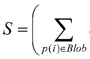
其中 5*为运动熵, 。6为运动连通区域, ')为视频帧中的运动角点, 为 的景深权重, 为 ·)对应的运动角点光流, 为方向直方图的标准差度 量, 表示 Blob内所有运动角点的方向直方图的方向一致性度量。
14. 根据权利要求 12或 13所述的视频中剧烈运动的检测装置, 其特 征在于, 还包括, 方向统计单元,用于根据视频帧中所有运动角点光流计算方向直方图的 标准差度量 f ff) 排除单元, 用于判断所述方向统计单元所得的 是否在预先设定的上 门限和下门限之间, 如果是, 则允许所述熵计算单元计算运动熵, 否则禁止 所述熵计算单元计算运动熵并将该视频帧判定为没有剧烈运动;
其中上门限大于下门限。
15. 根据权利要求 14所述的视频中剧烈运动的检测装置,其特征在于, 将每一个视频帧中最大的运动连通区域的运动熵与预先设定的运动熵 阈值相比较, 并对大于该运动熵阈值的视频帧进行统计;
如果在连续的 X 个视频帧中, 大于所述运动熵阈值的视频帧的数目大 于 Y, 则输出表示存在剧烈运动的信号, 其中 Y是预先设定的门限, X大于 或等于 Y。
Applications Claiming Priority (2)
| Application Number | Priority Date | Filing Date | Title |
|---|---|---|---|
| CN201110173948.3A CN102708571B (zh) | 2011-06-24 | 2011-06-24 | 视频中剧烈运动的检测方法及其装置 |
| CN201110173948.3 | 2011-06-24 |
Publications (1)
| Publication Number | Publication Date |
|---|---|
| WO2012174804A1 true WO2012174804A1 (zh) | 2012-12-27 |
Family
ID=46901291
Family Applications (1)
| Application Number | Title | Priority Date | Filing Date |
|---|---|---|---|
| PCT/CN2011/080071 Ceased WO2012174804A1 (zh) | 2011-06-24 | 2011-09-23 | 视频中剧烈运动的检测方法及其装置 |
Country Status (2)
| Country | Link |
|---|---|
| CN (1) | CN102708571B (zh) |
| WO (1) | WO2012174804A1 (zh) |
Families Citing this family (14)
| Publication number | Priority date | Publication date | Assignee | Title |
|---|---|---|---|---|
| CN103810718B (zh) * | 2012-11-15 | 2016-07-06 | 浙江大华技术股份有限公司 | 一种剧烈运动目标检测方法和装置 |
| CN103902954B (zh) * | 2012-12-26 | 2018-06-26 | 中国移动通信集团贵州有限公司 | 一种不良视频的鉴别方法和系统 |
| CN103693532B (zh) * | 2013-12-26 | 2016-04-27 | 江南大学 | 一种电梯轿厢内暴力行为检测方法 |
| CN103942793B (zh) * | 2014-04-16 | 2016-11-16 | 上海交通大学 | 基于热扩散的视频一致运动区域检测方法 |
| CN106570557A (zh) * | 2015-10-13 | 2017-04-19 | 富士通株式会社 | 运动物体的计数装置及方法 |
| CN108038432A (zh) * | 2017-11-30 | 2018-05-15 | 中国人民解放军国防科技大学 | 一种基于光流计数的公交人流统计方法及系统 |
| CN110337668B (zh) * | 2018-04-27 | 2021-08-31 | 深圳市大疆创新科技有限公司 | 图像增稳方法和装置 |
| CN109544601A (zh) * | 2018-11-27 | 2019-03-29 | 天津工业大学 | 一种基于在线学习的目标检测与跟踪方法 |
| MY200192A (en) * | 2018-11-29 | 2023-12-13 | Mimos Berhad | A system and method for detecting aggressive behaviour |
| CN110298323B (zh) * | 2019-07-02 | 2021-10-15 | 中国科学院自动化研究所 | 基于视频分析的打架检测方法、系统、装置 |
| CN112422863B (zh) | 2019-08-22 | 2022-04-12 | 华为技术有限公司 | 一种视频拍摄方法、电子设备和存储介质 |
| CN111161313B (zh) * | 2019-12-16 | 2023-03-14 | 华中科技大学鄂州工业技术研究院 | 一种视频流中的多目标追踪方法及装置 |
| CN111539301B (zh) * | 2020-04-20 | 2023-04-18 | 贵州安防工程技术研究中心有限公司 | 一种基于视频分析技术的场景混乱程度判别方法 |
| CN111507977B (zh) * | 2020-04-28 | 2024-04-02 | 同济大学 | 一种图像中钡剂信息提取方法 |
Citations (3)
| Publication number | Priority date | Publication date | Assignee | Title |
|---|---|---|---|---|
| US20060285724A1 (en) * | 2005-06-20 | 2006-12-21 | Ying-Li Tian | Salient motion detection system, method and program product therefor |
| CN101339602A (zh) * | 2008-07-15 | 2009-01-07 | 中国科学技术大学 | 一种基于光流法的视频火灾烟雾图像识别方法 |
| CN101751678A (zh) * | 2009-12-16 | 2010-06-23 | 北京智安邦科技有限公司 | 一种人群剧烈运动的检测方法及装置 |
Family Cites Families (2)
| Publication number | Priority date | Publication date | Assignee | Title |
|---|---|---|---|---|
| US6647131B1 (en) * | 1999-08-27 | 2003-11-11 | Intel Corporation | Motion detection using normal optical flow |
| JP2012523641A (ja) * | 2009-04-14 | 2012-10-04 | コーニンクレッカ フィリップス エレクトロニクス エヌ ヴィ | ビデオコンテンツ解析のためのキーフレーム抽出 |
-
2011
- 2011-06-24 CN CN201110173948.3A patent/CN102708571B/zh active Active
- 2011-09-23 WO PCT/CN2011/080071 patent/WO2012174804A1/zh not_active Ceased
Patent Citations (3)
| Publication number | Priority date | Publication date | Assignee | Title |
|---|---|---|---|---|
| US20060285724A1 (en) * | 2005-06-20 | 2006-12-21 | Ying-Li Tian | Salient motion detection system, method and program product therefor |
| CN101339602A (zh) * | 2008-07-15 | 2009-01-07 | 中国科学技术大学 | 一种基于光流法的视频火灾烟雾图像识别方法 |
| CN101751678A (zh) * | 2009-12-16 | 2010-06-23 | 北京智安邦科技有限公司 | 一种人群剧烈运动的检测方法及装置 |
Also Published As
| Publication number | Publication date |
|---|---|
| CN102708571B (zh) | 2014-10-22 |
| CN102708571A (zh) | 2012-10-03 |
Similar Documents
| Publication | Publication Date | Title |
|---|---|---|
| CN102708571B (zh) | 视频中剧烈运动的检测方法及其装置 | |
| CN109076198B (zh) | 基于视频的对象跟踪遮挡检测系统、方法和设备 | |
| US9767570B2 (en) | Systems and methods for computer vision background estimation using foreground-aware statistical models | |
| JP5701005B2 (ja) | 物体検知装置、物体検知方法、監視カメラシステム、およびプログラム | |
| US10896495B2 (en) | Method for detecting and tracking target object, target object tracking apparatus, and computer-program product | |
| JP6969871B2 (ja) | 移動状況推定装置、移動状況推定方法およびプログラム | |
| US10692225B2 (en) | System and method for detecting moving object in an image | |
| WO2013103591A1 (en) | Context aware moving object detection | |
| JP2008192131A (ja) | 特徴レベル・セグメンテーションを実行するシステムおよび方法 | |
| CN103530893A (zh) | 相机抖动场景下基于背景差和运动信息的前景检测方法 | |
| CN103700087A (zh) | 移动侦测方法和装置 | |
| CN106548488A (zh) | 一种基于背景模型及帧间差分的前景检测方法 | |
| JP2006216046A (ja) | ビデオのフレームのシーケンスにおける背景をモデル化するコンピュータが実施する方法 | |
| CN108198208B (zh) | 一种基于目标跟踪的移动侦测方法 | |
| US9742992B2 (en) | Non-uniform curve sampling method for object tracking | |
| CN103475800B (zh) | 图像序列中前景的检测方法和装置 | |
| KR100659781B1 (ko) | 씨씨디 영상에서의 연기 검출방법 및 장치 | |
| JP6652051B2 (ja) | 検出システム、検出方法及びプログラム | |
| CN106447685B (zh) | 一种红外跟踪方法 | |
| JP7243372B2 (ja) | 物体追跡装置および物体追跡方法 | |
| CN106898014B (zh) | 一种基于深度相机的入侵检测方法 | |
| Álvarez-Meza et al. | Background modeling using object-based selective updating and correntropy adaptation | |
| CN107067411B (zh) | 一种结合密集特征的Mean-shift跟踪方法 | |
| Zhang et al. | Study on moving-objects detection technique in video surveillance system | |
| Wang et al. | Adaptive spatiotemporal background modelling |
Legal Events
| Date | Code | Title | Description |
|---|---|---|---|
| 121 | Ep: the epo has been informed by wipo that ep was designated in this application |
Ref document number: 11868407 Country of ref document: EP Kind code of ref document: A1 |
|
| NENP | Non-entry into the national phase |
Ref country code: DE |
|
| 32PN | Ep: public notification in the ep bulletin as address of the adressee cannot be established |
Free format text: NOTING OF LOSS OF RIGHTS PURSUANT TO RULE 112(1) EPC (EPO FORM 1205A DATED 10/06/2014) |
|
| 122 | Ep: pct application non-entry in european phase |
Ref document number: 11868407 Country of ref document: EP Kind code of ref document: A1 |