WO2012172977A1 - 移動局装置、基地局装置、通信システム、通信方法および集積回路 - Google Patents
移動局装置、基地局装置、通信システム、通信方法および集積回路 Download PDFInfo
- Publication number
- WO2012172977A1 WO2012172977A1 PCT/JP2012/063891 JP2012063891W WO2012172977A1 WO 2012172977 A1 WO2012172977 A1 WO 2012172977A1 JP 2012063891 W JP2012063891 W JP 2012063891W WO 2012172977 A1 WO2012172977 A1 WO 2012172977A1
- Authority
- WO
- WIPO (PCT)
- Prior art keywords
- sequence
- mobile station
- type cell
- station apparatus
- information indicating
- Prior art date
- Legal status (The legal status is an assumption and is not a legal conclusion. Google has not performed a legal analysis and makes no representation as to the accuracy of the status listed.)
- Ceased
Links
Images





Classifications
-
- H—ELECTRICITY
- H04—ELECTRIC COMMUNICATION TECHNIQUE
- H04L—TRANSMISSION OF DIGITAL INFORMATION, e.g. TELEGRAPHIC COMMUNICATION
- H04L5/00—Arrangements affording multiple use of the transmission path
- H04L5/0001—Arrangements for dividing the transmission path
- H04L5/0003—Two-dimensional division
- H04L5/0005—Time-frequency
- H04L5/0007—Time-frequency the frequencies being orthogonal, e.g. OFDM(A) or DMT
-
- H—ELECTRICITY
- H04—ELECTRIC COMMUNICATION TECHNIQUE
- H04L—TRANSMISSION OF DIGITAL INFORMATION, e.g. TELEGRAPHIC COMMUNICATION
- H04L5/00—Arrangements affording multiple use of the transmission path
- H04L5/003—Arrangements for allocating sub-channels of the transmission path
- H04L5/0048—Allocation of pilot signals, i.e. of signals known to the receiver
- H04L5/0051—Allocation of pilot signals, i.e. of signals known to the receiver of dedicated pilots, i.e. pilots destined for a single user or terminal
-
- H—ELECTRICITY
- H04—ELECTRIC COMMUNICATION TECHNIQUE
- H04W—WIRELESS COMMUNICATION NETWORKS
- H04W56/00—Synchronisation arrangements
Definitions
- the present invention relates to a mobile station apparatus and a base station apparatus in which an uplink transmission timing setting procedure is executed for a plurality of uplink frequency bands in a communication system including a plurality of mobile station apparatuses and a base station apparatus.
- a communication system, a communication method, and an integrated circuit are examples of a communication method, and an integrated circuit.
- LTE Long Term Evolution
- EUTRA Evolved Universal Terrestrial Radio Access
- 3GPP Third Generation Partnership Project
- an orthogonal frequency division multiplexing (OFDM) method which is multicarrier transmission, is used as a communication method (downlink; referred to as DL) from a base station device to a mobile station device.
- SC-FDMA Single-Carrier Frequency Multiple Access
- uplink uplink; referred to as UL
- UL Uplink
- DFT-Spread OFDM Discrete Fourier Transform-Spread OFDM
- LTE-A Long Term Evolution-Advanced
- A-EUTRA Universal Terrestrial Radio Access
- LTE-A it is required to realize backward compatibility with LTE.
- a base station apparatus compatible with LTE-A communicates simultaneously with both mobile station apparatuses compatible with LTE-A and mobile station apparatuses compatible with LTE, and mobile stations compatible with LTE-A
- LTE-A There is a demand for LTE-A to realize that the apparatus communicates with a base station apparatus compatible with LTE-A and a base station apparatus compatible with LTE.
- LTE-A is studying to support at least the same channel structure as LTE.
- a channel means a medium used for signal transmission.
- a channel used in the physical layer is called a physical channel, and a channel used in a media access (MAC) layer is called a “logical channel”.
- Physical channel types include physical downlink shared channel (PDSCH) used for transmission / reception of downlink data and control information, and physical downlink control channel (PDCCH) used for transmission / reception of downlink control information.
- PDSCH physical downlink shared channel
- PDCCH physical downlink control channel
- Physical Downlink Control Channel Physical Uplink Shared Channel (PUSCH) used for transmission / reception of uplink data and control information
- Physical Uplink Control Channel (PUCCH: Physical Uplink) used for transmission / reception of control information Control CHannel)
- SCH Synchronization CHannel
- PRACH Physical Random Access CHannel
- PBCH Physical Broadcast CHannel
- a mobile station apparatus or a base station apparatus arranges and transmits a signal generated from control information and data on each physical channel. Data transmitted on the physical downlink shared channel or the physical uplink shared channel is referred to as a “transport block”.
- LTE-A uses a plurality of frequency bands having the same channel structure as LTE (hereinafter referred to as “component carrier (CC)” and also referred to as “element frequency band”).
- component carrier CC
- element frequency band a frequency band having the same channel structure as LTE
- Techniques to be used as frequency bands are being studied.
- frequency aggregation spectrum aggregation
- carrier aggregation CA: carrier aggregation
- Frequency aggregation Frequency aggregation
- a downlink physical channel is transmitted and received for each downlink component carrier (hereinafter referred to as “downlink component carrier; DL CC”).
- uplink component carrier UL CC
- carrier aggregation is a technique in which a base station apparatus and a mobile station apparatus simultaneously transmit and receive signals on a plurality of physical channels using a plurality of CCs on the uplink and the downlink.
- Carrier aggregation is communication by a plurality of cells using a plurality of frequency bands, and is also referred to as “cell aggregation”.
- cell aggregation a plurality of cells are defined as two different types of cells, one cell is defined as a primary cell (PCell), and the other cells are defined as secondary cells (SCell: Secondary Cell).
- the base station apparatus independently sets the PCell and SCell for each mobile station apparatus that uses cell aggregation.
- the PCell is always composed of a set (combination) of one DL CC and one UL CC.
- An SCell is composed of at least one DL CC, and a UL CC may or may not be configured.
- the CC used in the PCell is referred to as “primary component carrier (PCC)”.
- the CC used in the SCell is referred to as “secondary component carrier (SCC: Secondary CC)”.
- PCC primary component carrier
- SCC Secondary CC
- PCell and SCell data communication using PDSCH and PUSCH is performed in common, but other various processes are performed differently. Briefly, a plurality of processes are performed only by the PCell and not performed by the SCell. For example, in PCell, acquisition of system information in the downlink and determination of radio quality deficiency (RLF: Radio Link Failure) are performed, and random access procedures for initial connection and scheduling requests using PRACH in the uplink. And transmission / reception of uplink control information using PUCCH are performed. Basically, all the processes performed in LTE without using cell aggregation are performed in PCell, and a plurality of processes other than data communication
- LTE-A it is considered to use repeaters for some cells in a plurality of cells. In addition, it is considered to use different repeaters in different cells among a plurality of cells.
- the propagation environment differs between cells, and the arrival timing of the signal transmitted from the mobile station device at the base station device differs between cells. For this reason, in order to maintain uplink synchronization with the mobile station apparatus in each cell, the base station apparatus independently transmits signals for measuring uplink synchronization deviation to the mobile station apparatus in several cells. Need to be sent to.
- the base station apparatus instructs the mobile station apparatus to execute a random access procedure for a cell that is considered to need to measure uplink synchronization loss.
- the base station apparatus transmits information indicating a preamble (RACH preamble) sequence to be transmitted using the PRACH to the mobile station apparatus using the PDCCH.
- the mobile station apparatus transmits the preamble sequence indicated by the information included in the received PDCCH to the base station apparatus using the PRACH in the cell UL CC.
- the RACH preamble explicitly assigned by the base station apparatus is referred to as “Dedicated preamble”.
- an instruction by PDCCH including information indicating a preamble sequence is referred to as “PDCCH order”.
- the base station apparatus that has detected the Dedicated preamble transmits information (TA command) indicating uplink transmission timing adjustment values (TA: Timing Advance, Timing Adjustment, and Timing Alignment) to the mobile station apparatus.
- the mobile station apparatus receives information indicating the adjustment value of the uplink transmission timing in the DL CC of the cell that has transmitted the Dedicated preamble.
- the mobile station apparatus adjusts the uplink transmission timing of the cell based on the received information indicating the adjustment value of the uplink transmission timing.
- a random access procedure for measuring uplink synchronization shift is performed only by PCell, The adjustment value of the uplink transmission timing used for the PCell is also used for the SCell.
- the mobile station apparatus performs a random access procedure for measuring the uplink synchronization shift for the SCell independently of the procedure for the PCell.
- the downlink control information transmitted / received on the PDCCH includes control information related to allocation of PDSCH resources.
- a technique referred to as “Cross carrier scheduling” in which a PDCCH and a PDSCH including control information related to resource allocation in the PDCCH are arranged in different DL CCs is being studied.
- the DL CC in which the PDSCH is arranged is referred to as a “physical downlink shared channel component carrier (PDSCH CC)”.
- the DL CC in which the PDCCH is arranged is referred to as a “physical downlink control channel component carrier (PDCCH CC)”.
- all DL CCs are PDSCH CCs.
- the base station apparatus determines, for each mobile station apparatus, which DL CC to use as the PDCCH CC among the plurality of DL CCs used for carrier aggregation.
- the base station apparatus determines, for each mobile station apparatus, which PDCCH CC is associated with which PDSCH CC.
- the association between the PDCCH CC and the PDSCH CC means that a PDCCH including control information related to allocation of PDSCH resources arranged in the PDSCH CC is arranged in the PDCCH CC associated with the PDSCH CC. means.
- the base station apparatus notifies the mobile station apparatus of information indicating the DL CC associated with each PDSCH CC as a PDCCH CC. Based on the information notified from the base station apparatus, the mobile station apparatus recognizes a DL CC in which a PDCCH including control information related to PDSCH resource allocation of each PDSCH CC may be arranged.
- the PDSCH CC and the PDCCH CC associated with the PDSCH CC may be the same DL CC. In this case, information indicating the DL CC associated as the PDCCH CC may not be explicitly notified to the mobile station apparatus.
- a plurality of PDSCH CCs may be associated with one PDCCH CC. In other words, a plurality of PDSCH CCs may be associated with the same PDCCH CC.
- Cross carrier scheduling is used when there is a large amount of interference from cells managed by different base station apparatuses in some cells, and it is difficult for the mobile station apparatus to receive the PDCCH while satisfying the required quality.
- the PDSCH can improve the error rate characteristics by combining HARQ (Hybrid Automatic Repeat reQuest) and combining the retransmission data with the data at the previous transmission. Therefore, the mobile station apparatus can acquire data from the PDSCH while satisfying the required quality even in a cell with large interference.
- HARQ Hybrid Automatic Repeat reQuest
- the mobile station device transmits a Dedicated preamble, and information indicating an uplink transmission timing adjustment value in the DL CC of the cell. Even if it operates to receive, it is affected by interference from cells managed by different base station apparatuses, and PDCCH cannot be appropriately received. As a result, there has been a problem that the mobile station apparatus cannot properly receive information indicating an adjustment value of uplink transmission timing.
- the present invention has been made in view of the above points, and an object of the present invention is to provide uplink communication with respect to a plurality of uplink frequency bands in a communication system including a plurality of mobile station apparatuses and base station apparatuses.
- the present invention relates to a mobile station apparatus, a base station apparatus, a communication system, a communication method, and an integrated circuit that can efficiently execute a transmission timing setting procedure.
- the mobile station apparatus of the present invention is a mobile station apparatus that communicates with a base station apparatus using a first type cell and a second type cell.
- the mobile station apparatus includes (i) the first type When the sequence is transmitted in the cell, as a response to the sequence transmission, information indicating an identifier corresponding to the sequence and information indicating the adjustment value for the first type cell transmitting the sequence When received from the base station device, the sequence transmission processing is terminated.
- the sequence When the sequence is transmitted in the second type cell, the sequence is assigned to the own device in advance as a response to the sequence transmission.
- transmission processing of the sequence Finished Upon receiving from the base station device information indicating a mobile station device identifier and information indicating the adjustment value for the second type cell that transmitted the sequence, transmission processing of the sequence Finished, during a predetermined time period from the transmission of the (iii) the sequence, if not a response to the transmission of the sequence received from the base station apparatus performs transmission processing for transmitting the sequence again.
- the adjustment value is configured in one of the first format and the second format.
- the first format has a larger number of bits indicating the adjustable range of uplink transmission timing than the second format.
- the adjustment value for the second type cell is configured in the first format when included in the response to the transmission of the sequence, and the second value when not included in the response to the transmission of the sequence. It is composed of the format.
- the base station apparatus of the present invention is a base station apparatus that communicates with a mobile station apparatus using a first type cell and a second type cell.
- the base station apparatus In the reception processing of the sequence used for estimating the adjustment value of the uplink transmission timing in the first type cell or the second type cell, the base station apparatus is (i) the first type When receiving the sequence in the cell, information indicating an identifier corresponding to the sequence and information indicating the adjustment value for the first type cell that has received the sequence are received as a response to the reception of the sequence.
- the adjustment value is configured in one of the first format and the second format.
- the first format has a larger number of bits indicating the adjustable range of uplink transmission timing than the second format.
- the base station apparatus is configured in the first format when the adjustment value for the second type cell is included in the response to the reception of the sequence, and when not included in the response to the reception of the sequence. Configure in the second format.
- the communication system of the present invention includes a plurality of mobile station apparatuses and a base station apparatus that communicates with the plurality of mobile station apparatuses, and includes a first type cell and a second type cell.
- the mobile station apparatus includes (i) the first type When the sequence is transmitted in the cell, as a response to the sequence transmission, information indicating an identifier corresponding to the sequence and information indicating the adjustment value for the first type cell transmitting the sequence When received from the base station device, the sequence transmission processing is terminated.
- the sequence When the sequence is transmitted in the second type cell, the sequence is assigned to the own device in advance as a response to the sequence transmission.
- transmission processing of the sequence Finished Upon receiving from the base station device information indicating a mobile station device identifier and information indicating the adjustment value for the second type cell that transmitted the sequence, transmission processing of the sequence Finished, during a predetermined time period from the transmission of the (iii) the sequence, if not a response to the transmission of the sequence received from the base station apparatus performs transmission processing for transmitting the sequence again.
- the base station apparatus In the reception processing of the sequence in the first type cell or the second type cell, the base station apparatus (i) when receiving the sequence in the first type cell, the sequence As a response to the reception of, transmitting information indicating an identifier corresponding to the sequence and information indicating the adjustment value for the first type cell that has received the sequence to the mobile station device, (ii) When the sequence is received by a second type cell, as a response to reception of the sequence, information indicating a mobile station device identifier pre-assigned to the mobile station device, and the second type of cell that has received the sequence Information indicating the adjustment value for the cell is transmitted to the mobile station apparatus.
- the communication method of the present invention is used for a mobile station apparatus that communicates with a base station apparatus using a first type cell and a second type cell.
- the communication method uses the sequence in the first type cell.
- information indicating an identifier corresponding to the sequence and information indicating the adjustment value for the first type cell that has transmitted the sequence are transmitted from the base station apparatus.
- a mobile station apparatus identifier pre-assigned to the own apparatus is indicated as a response to the sequence transmission
- the sequence transmission processing is terminated. And at least a step of performing transmission processing for transmitting the sequence again if a response to the transmission of the sequence is not received from the base station apparatus during a predetermined period after transmitting the sequence.
- the adjustment value is configured by one of the first format and the second format.
- the first format has a larger number of bits indicating the adjustable range of uplink transmission timing than the second format.
- the adjustment value for the second type cell is configured in the first format when included in the response to the transmission of the sequence, and the second format when not included in the response to the transmission of the sequence. Consists of.
- the communication method of the present invention is used for a base station apparatus that communicates with a mobile station apparatus using a first type cell and a second type cell.
- the communication method includes: receiving a sequence used for estimating an adjustment value of uplink transmission timing in the first type cell or the second type cell; In response to reception of the sequence, information indicating an identifier corresponding to the sequence and information indicating the adjustment value for the first type cell that has received the sequence are transmitted to the mobile station apparatus.
- information indicating a mobile station apparatus identifier assigned in advance to the mobile station apparatus and the sequence are received Transmitting information indicating the adjustment value for the second type cell to the mobile station apparatus.
- the adjustment value is configured in one of the first format and the second format.
- the first format has a larger number of bits indicating the adjustable range of uplink transmission timing than the second format.
- the adjustment value for the second type cell is configured in the first format when included in a response to reception of the sequence, and the adjustment value is not included in a response to reception of the sequence.
- the method further includes configuring in two formats.
- the integrated circuit of the present invention is mounted on the mobile station apparatus, thereby causing the mobile station apparatus to exhibit a plurality of functions.
- the integrated circuit causes the mobile station apparatus to perform a function of communicating with the base station apparatus using the first type cell and the second type cell.
- the integrated circuit includes: (i) the first type cell in transmission processing of a sequence used for estimating an adjustment value of uplink transmission timing in the first type cell or the second type cell.
- the adjustment value is configured in one of the first format and the second format.
- the first format has a larger number of bits indicating the adjustable range of uplink transmission timing than the second format.
- the adjustment value for the second type cell is configured in the first format when included in the response to the transmission of the sequence, and the second format when not included in the response to the transmission of the sequence. Consists of.
- the integrated circuit of the present invention is mounted on the base station apparatus, thereby causing the base station apparatus to exhibit a plurality of functions.
- the integrated circuit causes the base station apparatus to exhibit a function of communicating with the mobile station apparatus using the first type cell and the second type cell.
- the integrated circuit includes: (i) the first type cell When the sequence is received, the information indicating the identifier corresponding to the sequence and the information indicating the adjustment value for the first type cell that has received the sequence are transferred as a response to the reception of the sequence.
- the base station apparatus further exhibits a function of transmitting information indicating the adjustment value for the second type cell that has received the sequence to the mobile station apparatus.
- the adjustment value is configured in one of the first format and the second format.
- the first format has a larger number of bits indicating the adjustable range of uplink transmission timing than the second format.
- the integrated circuit is configured in the first format when the adjustment value for the second type cell is included in the response to the reception of the sequence, and when not included in the response to the reception of the sequence.
- the base station apparatus further exhibits the function configured in the second format.
- the present specification describes the present invention in terms of improvement of a communication system, a base station device, a mobile station device, a communication method, and an integrated circuit when the mobile station device and the base station device are connected using a plurality of frequency bands.
- the communication method to which the present invention is applicable is not limited to a communication method that is upward compatible with LTE, such as LTE or LTE-A.
- the present invention can be applied to UMTS (Universal Mobile Telecommunications System).
- the procedure for setting the uplink transmission timing can be efficiently executed for a plurality of uplink frequency bands.
- FIG. 7 is a flowchart showing an example of processing related to a non-contention based random access procedure of the mobile station apparatus 5 according to the embodiment of the present invention. It is a flowchart which shows an example of the process regarding the non-contention based random access procedure of the base station apparatus 3 which concerns on embodiment of this invention. It is a figure explaining the outline about the whole picture of the communications system concerning the embodiment of the present invention. It is a figure which shows schematic structure of the time frame of the downlink from the base station apparatus 3 which concerns on embodiment of this invention to the mobile station apparatus 5. FIG. It is a figure which shows schematic structure of the time frame of the uplink from the mobile station apparatus 5 which concerns on embodiment of this invention to the base station apparatus 3. FIG.
- CDMA code division multiple access
- TDMA time division multiple access
- FDMA frequency division multiple access
- OFDMA orthogonal FDMA
- SC-FDMA single carrier FDMA
- a CDMA system may implement a radio technology (standard) such as Universal Terrestrial Radio Access (UTRA) or cdma2000®.
- UTRA includes Wideband CDMA (WCDMA) and other improved versions of CDMA.
- cdma2000 covers IS-2000, IS-95, and IS-856 standards.
- a TDMA system may implement a radio technology such as Global System for Mobile Communications (GSM).
- GSM Global System for Mobile Communications
- OFDMA systems include Evolved UTRA (E-UTRA), Ultra Mobile Broadband (UMB), IEEE 802.11 (Wi-Fi), IEEE 802.16 (WiMAX), IEEE 802.20, Flash-OFDM (registered trademark), etc.
- Wireless technology may be implemented.
- UTRA and E-UTRA are part of the universal mobile communication system (UMTS).
- 3GPP LTE Long Term Evolution
- LTE-A Long Term Evolution
- UTRA, E-UTRA, UMTS, LTE, LTE-A and GSM® are described in documents from an organization named Third Generation Partnership Project (3GPP).
- cdma2000 and UMB are described in documents from an organization named Third Generation Partnership Project 2 (3GPP2).
- 3GPP2 Third Generation Partnership Project 2
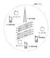
- FIG. 9 is a diagram illustrating an outline of the overall image of the communication system according to the embodiment of the present invention.
- a communication system 1 illustrated in FIG. 9 includes a base station device (also referred to as “eNodeB”, “NodeB”, or “access point”) 3, a plurality of repeaters 4A, 4B, and 4C, and a plurality of mobile station devices ( 5A, 5B, and 5C communicate with each other.
- eNodeB also referred to as “eNodeB”, “NodeB”, or “access point”
- a base station device also referred to as “eNodeB”, “NodeB”, or “access point”
- a plurality of repeaters 4A, 4B, and 4C and a plurality of mobile station devices ( 5A, 5B, and 5C communicate with each other.
- 5A, 5B, and 5C communicate with each other.
- the communication system according to the embodiment of the present invention may include other network entities.
- the base station device 3 can move the mobile station devices 5A, 5B, and 5C through the repeaters 4A, 4B, and 4C or without the repeaters 4A, 4B, and 4C depending on the positions of the mobile station devices 5A, 5B, and 5C. And wireless communication.
- the downlink (also referred to as “DL: Downlink”) that is the communication direction from the base station apparatus 3 to the mobile station apparatuses 5A, 5B, and 5C is a downlink pilot channel (downlink reference signal).
- a physical downlink control channel also referred to as “PDCCH: Physical Downlink Control CHannel”
- PDSCH Physical Downlink Shared CHannel
- the communication directions from the repeaters 4A, 4B, and 4C to the mobile station apparatuses 5A, 5B, and 5C are also downlinks.
- FIG. 9 shows that the uplink (also referred to as “UL: Uplink”) in the communication direction from the mobile station devices 5A, 5B, 5C to the base station device 3 is a physical uplink shared channel (“PUSCH: Physical Uplink Shared”). It is also referred to as “CHannel”), an uplink pilot channel (uplink reference signal), and a physical uplink control channel (also referred to as “PUCCH: Physical Uplink Control CHannel”).
- CHannel Physical Uplink shared channel
- PUCCH Physical Uplink Control CHannel
- the communication directions from the mobile station devices 5A, 5B, and 5C to the repeaters 4A, 4B, and 4C are also uplinks.
- Channel means a medium used for signal transmission.
- a channel used in the physical layer is referred to as a “physical channel”
- a channel used in a media access (MAC) layer is referred to as a “logical channel”.
- the PDSCH is a physical channel used for transmission / reception of downlink data and control information.
- the PDCCH is a physical channel used for transmission / reception of downlink control information.
- PUSCH is a physical channel used for transmission / reception of uplink data and control information.
- PUCCH is a physical channel used for transmission / reception of uplink control information (uplink control information; UCI: Uplink Control Information).
- an acknowledgment (ACK: Acknowledgement) or a negative acknowledgment (NACK: Negative Acknowledgment) indicating a PDSCH downlink data, and whether to request resource allocation
- ACK Acknowledgement
- NACK Negative Acknowledgment
- SR resource allocation
- SCH synchronization channel
- PRACH physical random access channel
- PBCH physical broadcast channel
- the PDSCH is also used for transmission of downlink system information.
- the mobile station devices 5A, 5B, 5C, or the base station device 3 arranges and transmits signals generated from control information and data in each physical channel. Data transmitted on the PDSCH or PUSCH is referred to as a “transport block”. In addition, an area managed by the base station apparatus 3 is referred to as a “cell”. Even if the base station device 3 and the mobile station devices 5A, 5B, and 5C actually communicate via the repeaters 4A, 4B, and 4C, the mobile station devices 5A, 5B, and 5C are connected to the repeater 4A, Processing is not performed in consideration of the existence of 4B and 4C, and communication is performed by regarding the repeaters 4A, 4B and 4C as the base station apparatus 3.
- the mobile station devices 5A, 5B, and 5C are referred to as “mobile station device 5”, and the repeaters 4A, 4B, and 4C are included in the base station device 3 for explanation.
- a communication system 1 using a repeater (frequency selectivity repeater) will be described.
- the present invention can also be applied to a communication system using “Radio Unit”).
- the RRH is managed by the base station apparatus 3 and transmission / reception is controlled.
- a base station apparatus with a wide coverage is generally called a “macro base station apparatus”.
- a base station apparatus with narrow coverage is generally called a “pico base station apparatus” or a “femto base station apparatus”.
- RRH is generally considered to be used in an area where the coverage is narrower than that of a macro base station apparatus, and is considered to be used as a role such as a pico base station apparatus and a femto base station apparatus.
- the present invention can be applied to a communication system configured by a macro base station apparatus and an RRH, and a coverage supported by the macro base station apparatus including part or all of the coverage supported by the RRH.
- a communication system deployment is referred to as a “heterogeneous network deployment”.
- the base station apparatus 3 corresponds to the macro base station apparatus
- the repeater corresponds to the RRH.
- the propagation environment differs between the cells, and the arrival timing of the signal transmitted from the mobile station device 5 at the base station device 3 differs between cells.
- ⁇ Carrier aggregation / Cell aggregation> In the communication system according to the embodiment of the present invention, communication is performed using a plurality of frequency bands having a predetermined frequency bandwidth ("frequency band aggregation; spectrum aggregation", “carrier aggregation; CA”, “Frequency”). Also called “aggregation”).
- one frequency band is referred to as a “component carrier (CC)”.
- CC component carrier
- a downlink physical channel is transmitted and received for each downlink CC (referred to as “downlink component carrier; DL CC”), and an uplink CC (“ Uplink component carrier; referred to as UL CC ”), an uplink physical channel is transmitted and received.
- the base station apparatus 3 and the plurality of mobile station apparatuses 5 use a plurality of CCs in a plurality of physical channels in the uplink and the downlink. Send and receive signals simultaneously.
- the base station apparatus 3 communicates using one arbitrary frequency band in one cell.
- Carrier aggregation is communication by a plurality of cells using a plurality of frequency bands, and is also referred to as “cell aggregation”.
- cell aggregation one cell is defined as a primary cell (PCell: Primary Cell), and the remaining cells are defined as secondary cells (SCell: Secondary Cell).
- PCell Primary Cell
- SCell Secondary Cell
- the setting of PCell and SCell is performed independently for each mobile station apparatus 5.
- a PCell is always composed of a set of one DL CC and one UL CC.
- the SCell is composed of at least one DL CC, and the UL CC may or may not be configured.
- one SCell is composed of a set of one DL CC and one UL CC.
- the CC used in the PCell is referred to as “primary component carrier (PCC)”.
- the CC used in the SCell is referred to as “secondary component carrier (SCC: Secondary CC)”.
- PCell and SCell data communication using PDSCH and PUSCH is performed in common, but other various processes are performed differently. Briefly, a plurality of processes are performed only by the PCell and not performed by the SCell. For example, in PCell, (i) acquisition of system information and determination of lack of radio quality (RLF: Radio Link Failure) are performed in the downlink, and (ii) initial connection and scheduling using PRACH in the uplink. A random access procedure for a request (resource allocation request) is executed, and UCI transmission / reception using PUCCH is performed. A random access procedure for measuring uplink synchronization loss is executed in the PCell and at least some SCells, for example, repeaters or SCells connected via RRH.
- RLF Radio Link Failure
- the mobile station device 5A shown in FIG. 9 directly transmits and receives signals to and from the base station device 3 in a certain cell, and the base station device via a repeater 4A in a certain cell. 3 to send and receive signals.
- a cell in which signals are directly transmitted / received to / from the base station device 3 is set to PCell, and a cell in which signals are transmitted / received to / from the base station device 3 via the repeater 4A is set to SCell. Is done.
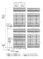
- FIG. 10 is a diagram showing a schematic configuration of a downlink time frame from the base station apparatus 3 to the mobile station apparatus 5 according to the embodiment of the present invention.
- the downlink time frame is a unit for resource allocation or the like, and is a resource block (RB: Resource Block (“Physical Resource Block; PRB: Physical Resource Block”) composed of a frequency band and a time zone of a predetermined downlink width. ))) Pair (referred to as “physical resource block pair; PRB pair”).
- One downlink PRB pair (referred to as a “downlink physical resource block pair; DL PRB pair”) is two PRBs consecutive in the downlink time domain (“downlink physical resource block; DL PRB”). It is called).
- one DL PRB is composed of 12 subcarriers (referred to as “downlink subcarriers”) in the downlink frequency domain, and 7 OFDM (orthogonal frequencies) in the time domain. It consists of symbols of Orthogonal Frequency Division Multiplexing.
- a downlink system band (referred to as a downlink system band) is a downlink communication band of the base station apparatus 3.
- the downlink system bandwidth (referred to as downlink system bandwidth) is composed of a plurality of downlink CC bandwidths (referred to as “downlink component carrier bandwidth”).
- a downlink CC (referred to as “downlink component carrier; DL CC”) is a band of a predetermined frequency bandwidth, and the downlink component carrier bandwidth is a frequency bandwidth of the DL CC. It is.
- the downlink system band with a frequency bandwidth of 40 MHz is composed of two DL CCs with a frequency bandwidth of 20 MHz.
- the downlink component carrier bandwidth is a frequency bandwidth that can be used for communication by the mobile station device 5 that supports LTE
- the downlink system bandwidth is that the mobile station device 5 that supports LTE-A. It is a frequency bandwidth that can be used for communication.
- the mobile station apparatus 5 compatible with LTE can communicate with only one cell at a time, and the mobile station apparatus 5 compatible with LTE-A can communicate with a plurality of cells simultaneously.
- the downlink component carrier bandwidth is a downlink frequency bandwidth of one cell, and the downlink system bandwidth is a collection of downlink frequency bandwidths of a plurality of cells.
- a slot composed of seven OFDM symbols (referred to as “downlink slot”) and a subframe composed of two downlink slots (“downlink sub-link”). Called “frame”).
- a unit composed of one downlink subcarrier and one OFDM symbol is referred to as a resource element (RE) or “downlink resource element”.
- RE resource element
- downlink resource element In each downlink subframe, at least a PDSCH used for transmitting information data (also referred to as a “transport block”) and a PDCCH used for transmitting control information are arranged.
- PDCCH is composed of the first to third OFDM symbols in the downlink subframe
- PDSCH is composed of the fourth to fourteenth OFDM symbols in the downlink subframe. Note that the number of OFDM symbols constituting the PDCCH and the number of OFDM symbols constituting the PDSCH may be changed for each downlink subframe.
- RS Reference signal
- Cell specific RS Cell specific RS
- DL RS downlink reference signal
- the downlink pilot channels to be transmitted are distributed and arranged in a plurality of downlink resource elements.
- the downlink reference signal is a signal known in the communication system 1 that is used for estimating propagation path fluctuations of the PDSCH and PDCCH signals. Note that the number of downlink resource elements constituting the downlink reference signal depends on the number of transmission antennas used for communication to the mobile station apparatus 5 in the base station apparatus 3.
- One PDSCH is composed of one or more DL PRBs in the same DL CC, and one PDCCH is composed of a plurality of downlink resource elements in the same DL CC.
- a plurality of PDSCHs and a plurality of PDCCHs are arranged in the downlink system band.
- the base station apparatus 3 transmits one PDCCH and one PDCCH including control information related to allocation of PDSCH resources in the same DL CC in the same downlink subframe to one mobile station apparatus 5 corresponding to LTE.
- One PDSCH can be arranged.
- the base station apparatus 3 transmits, to one mobile station apparatus 5 compatible with LTE-A, a plurality of PDCCHs and a plurality of PDSCHs including control information related to allocation of PDSCH resources in the same downlink subframe. Can be arranged. Note that the base station apparatus 3 includes control information related to allocation of a plurality of PDSCH resources in the same DL CC in the same downlink subframe with respect to one mobile station apparatus 5 corresponding to LTE-A. A plurality of PDCCHs can be arranged. However, the base station apparatus 3 cannot arrange a plurality of PDSCHs in the same DL CC. However, the base station apparatus 3 can arrange each PDSCH in a different DL CC.
- DCI Downlink control information
- DCI including information indicating DL PRB assignment to PDSCH is called “downlink assignment” or “Downlink grant”, and DCI including information indicating UL PRB assignment to PUSCH is “uplink It is called “link grant (UL grant)”.
- the downlink assignment is used as information on the PDCCH order when some resource allocation information fields indicate specific values. Specifically, the downlink assignment used as information regarding the PDCCH order includes at least information indicating a preamble sequence of a dedicated preamble and information indicating an uplink subframe of a PRACH that can transmit a dedicated preamble. Note that the downlink assignment includes a transmission power control command for PUCCH.
- the uplink assignment includes a transmission power control command for PUSCH.
- One PDCCH includes only information indicating the allocation of one PDSCH resource in one DL CC, or information indicating the allocation of one PUSCH resource in one UL CC. It does not include information indicating allocation of a plurality of PDSCH resources or information indicating allocation of a plurality of PUSCH resources.
- CRC Cyclic Redundancy Check
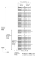
- FIG. 11 is a diagram showing a schematic configuration of an uplink time frame from the mobile station apparatus 5 to the base station apparatus 3 according to the embodiment of the present invention.
- the horizontal axis represents the time domain
- the vertical axis represents the frequency domain.
- the uplink time frame is a unit for resource allocation or the like, and is called a PRB pair ("UL PRB pair" referred to as UL physical resource block pair; UL PRB pair) composed of a frequency band and a time zone of a predetermined width of the uplink. .).
- One UL PRB pair is composed of two uplink PRBs (referred to as “uplink physical resource block; UL PRB”) that are continuous in the uplink time domain.
- one UL PRB is composed of 12 subcarriers (referred to as “uplink subcarriers”) in the uplink frequency domain, and 7 SC-FDMA (in the time domain). Single-Carrier Frequency Division Multiple Access) symbol.
- the uplink system band (referred to as “uplink system band”) is the uplink communication band of the base station apparatus 3.
- the uplink system bandwidth (referred to as “uplink system bandwidth”) is composed of a plurality of uplink CC frequency bandwidths (referred to as “uplink component carrier bandwidth”).
- an uplink CC (referred to as “uplink component carrier; UL CC”) is a band of a predetermined frequency bandwidth
- the uplink component carrier bandwidth is a frequency band of UL CC. It is.
- an uplink system band having a frequency bandwidth of 40 MHz (referred to as an “uplink system band”) is composed of two UL CCs having a frequency bandwidth of 20 MHz.
- a plurality of UL PRBs are arranged according to the uplink component carrier bandwidth.
- a UL CC with a frequency bandwidth of 20 MHz is composed of 100 UL PRBs.
- the uplink component carrier bandwidth is a frequency bandwidth that can be used for communication by the mobile station apparatus 5 that supports LTE.
- the uplink system bandwidth is a frequency bandwidth that can be used for communication by the mobile station apparatus 5 that supports LTE-A.
- the mobile station apparatus 5 corresponding to LTE can communicate with only one cell at a time.
- the mobile station apparatus 5 compatible with LTE-A can perform communication in a plurality of cells at the same time.
- the uplink component carrier bandwidth is an uplink frequency bandwidth of one cell.
- the uplink system bandwidth is a collection of uplink frequency bandwidths of a plurality of cells.
- uplink slot a slot composed of seven SC-FDMA symbols
- uplink subframe a subframe composed of two uplink slots
- uplink resource element A unit composed of one uplink subcarrier and one SC-FDMA symbol is referred to as a “resource element” or “uplink resource element”.
- each uplink subframe at least a PUSCH used for transmitting information data and a PUCCH used for transmitting uplink control information (UCI) are arranged. Also, a PRACH used for uplink synchronization establishment is arranged in any uplink subframe. Whether the PUCCH requests UCI (ACK / NACK) indicating an acknowledgment (ACK: Acknowledgement) or a negative acknowledgment (NACK: Negative Acknowledgment) for data received using the PDSCH, and allocation of uplink resources.
- UCI Scheduling Request
- UCI Channel Quality Indicator
- one PUSCH is composed of one or more UL PRBs in the same UL CC.
- One PUCCH is composed of two UL PRBs that are symmetrical in the frequency domain within the same UL CC and are located in different uplink slots.
- One PRACH is composed of six UL PRB pairs. For example, in FIG. 11, in the uplink subframe in the UL CC with the lowest frequency, the UL PRB with the lowest frequency in the first uplink slot and the UL PRB with the highest frequency in the second uplink slot Thus, one UL PRB pair used for PUCCH is configured. For example, in FIG.
- the base station apparatus 3 can allocate one PUSCH resource to one UL CC with respect to one mobile station apparatus 5 corresponding to LTE. Further, the base station apparatus 3 can allocate one PUSCH resource for each UL CC to one mobile station apparatus 5 corresponding to LTE-A.
- the mobile station apparatus 5 supporting LTE-A can transmit a signal using a plurality of PUSCH resources when a PUSCH resource is allocated by a plurality of UL CCs in the same uplink subframe. Note that the base station device 3 cannot allocate a plurality of PUSCH resources in the same UL CC in the same uplink subframe to one mobile station device 5 that supports LTE-A.
- Each PUSCH resource can be assigned to a different UL CC.
- the mobile station apparatus 5 uses only one PUCCH resource in the same uplink subframe.
- the mobile station apparatus 5 corresponding to LTE transmits a signal using only the PUSCH resource.
- the mobile station apparatus 5 supporting LTE-A uses the PUSCH resource based on the instruction of the base station apparatus 3 notified in advance. The signal is transmitted using only the PUCCH resource or the PUSCH resource.
- the UL CC to which the PUCCH resource is allocated is the uplink PCC, and the cell to which the PUCCH resource is allocated is the PCell.
- PUCCH resources and PUSCH resources are allocated in the same uplink subframe. In this case, a signal is transmitted using only PUSCH resources.
- PUCCH resources and PUSCH resources are allocated in the same uplink subframe Can basically transmit signals using both PUCCH resources and PUSCH resources.
- One or more PRACHs can be arranged in the uplink system band.
- only one PRACH can be arranged in the UL CC, and a plurality of PRACHs are not arranged.
- the mobile station apparatus 5 can use only one PRACH of UL CC in a certain uplink subframe.
- the base station apparatus 3 can control which uplink subframe in each UL CC and which PRACH is allocated to the UL PRB pair.
- the mobile station apparatus 5 can execute a random access procedure for an initial connection and a scheduling request (resource allocation request) using the PRACH of the PCell.
- the mobile station apparatus 5 can execute a random access procedure for measuring uplink synchronization shift using the PCell PRACH and the SCell PRACH in a connected state with the base station apparatus 3.
- the “connection state” can also be said to be a state in which parameters in the MAC layer, the RRC (Radio Resource Control) layer, and the like are appropriately set and held.
- the PRACH is a channel used for the mobile station apparatus 5 to transmit a preamble sequence used for estimating an uplink transmission timing adjustment value in the base station apparatus 3, and has a guard time.
- the preamble sequence 64 types of sequences are prepared, and are configured to express 6-bit information.
- a series of procedures relating to transmission / reception of PRACH and transmission / reception of a response to PRACH is referred to as “random access procedure”.
- Random access procedure There are two types of random access procedures: a Contention based Random Access (contention based random access) procedure and a Non-contention based Random Access (non-contention based random access) procedure.
- the Contention based Random Access procedure is a random access procedure in which a collision may occur in a preamble sequence transmitted between the mobile station devices 5.
- the collision of preamble sequences means that a plurality of mobile station apparatuses 5 transmit the same preamble sequence on the PRACH with the same frequency and the same time resource.
- the preamble sequence collision is also referred to as “random access collision”.
- the Contention based Random Access procedure is performed for an initial connection in a state where it is not connected (communication) with the base station apparatus 3 and for notifying a scheduling request while being connected to the base station apparatus 3.
- the non-contention based Random Access procedure is a random access procedure in which there is no possibility of collision in the preamble sequence transmitted between the mobile station devices 5.
- the Non-contention based Random Access procedure is appropriate when the base station device 3 and the mobile station device 5 are connected but the uplink is out of synchronization (not established or released). This is done to set the transmission timing of the link.
- “when uplink synchronization is out of sync” means that the uplink transmission timing adjustment value is not notified, or the valid period of the notified uplink transmission timing adjustment value has passed , And the notified uplink transmission timing adjustment value is reset.
- the base station apparatus 3 notifies the mobile station apparatus 5 of information indicating a preamble (RACH preamble) sequence transmitted on the PRACH using, for example, the PDCCH.
- the mobile station apparatus 5 transmits the preamble sequence indicated by the information included in the received PDCCH to the base station apparatus 3 using the PRACH in the cell UL CC.
- the RACH preamble explicitly assigned by the base station apparatus 3 is referred to as “Dedicated preamble”.
- the PDCCH instruction including information indicating the preamble sequence is referred to as “PDCCH order”.
- the mobile station apparatus 5 randomly selects and uses one preamble sequence from the preamble sequence that is not used as the Dedicated preamble at the start of the random access procedure.
- information indicating the number of preamble sequences used in each of the contention based random access procedure and the non-contention based random access procedure is base information as system information. The mobile station apparatus 5 is notified from the station apparatus 3.
- the uplink pilot channel is arranged in different SC-FDMA symbols depending on whether it is arranged in the same UL PRB as PUSCH or in the same UL PRB as PUCCH.
- the uplink pilot channel is used for transmitting an uplink reference signal (UL RS).
- UL RS uplink reference signal
- the “uplink reference signal” is a signal known in the communication system 1 that is used for estimating propagation path fluctuations of PUSCH and PUCCH.
- the uplink pilot channel When the uplink pilot channel is arranged in the same UL PRB as PUSCH, it is arranged in the fourth SC-FDMA symbol in the uplink slot.
- the uplink pilot channel When the uplink pilot channel is arranged in the same UL PRB as the PUCCH including ACK / NACK, it is arranged in the third, fourth and fifth SC-FDMA symbols in the uplink slot.
- the uplink pilot channel When the uplink pilot channel is arranged in the same UL PRB as the PUCCH including SR, it is arranged in the third, fourth and fifth SC-FDMA symbols in the uplink slot.
- the uplink pilot channel When the uplink pilot channel is arranged in the same UL PRB as the PUCCH including the CQI, it is arranged in the second and sixth SC-FDMA symbols in the uplink slot.
- FIG. 11 shows the case where the PUCCH is arranged in the UL PRB at the end in the frequency domain of each UL CC. Good.
- code multiplexing in the frequency domain and / or code multiplexing in the time domain is used.
- Code multiplexing in the frequency domain is processed by multiplying each code of the code sequence by a modulated signal modulated from uplink control information in subcarrier units.
- Code multiplexing in the time domain is processed by multiplying each code of the code sequence by the modulated signal modulated from the uplink control information in units of SC-FDMA symbols.
- a plurality of PUCCHs are arranged in the same UL PRB. Each PUCCH is assigned a different code. Code multiplexing is realized in the frequency domain or time domain by the assigned code.
- PUCCH In PUCCH (referred to as “PUCCH format 1a” or “PUCCH format 1b”) used to transmit ACK / NACK, code multiplexing in the frequency domain and time domain is used. In PUCCH used for transmitting SR (referred to as “PUCCH format 1”), code multiplexing in the frequency domain and time domain is used. In PUCCH (referred to as “PUCCH format 2”, “PUCCH format 2a”, or “PUCCH format 2b”) used for transmitting CQI, code multiplexing in the frequency domain is used. For simplification of description, description of the contents related to PUCCH code multiplexing is omitted as appropriate.
- the OFDM scheme is applied in the downlink and the NxDFT-Spread OFDM scheme is applied in the uplink.
- the “NxDFT-Spread OFDM scheme” is a scheme for transmitting and receiving signals using the DFT-Spread OFDM scheme in units of uplink component carriers, and the uplink subframe of the communication system 1 using a plurality of UL CCs. Is a method for performing communication using a plurality of processing units related to DFT-Spread OFDM transmission / reception.
- the PDSCH resource is arranged in the same downlink subframe as the downlink subframe in which the PDCCH resource including the downlink assignment used for the allocation of the PDSCH resource is arranged in the time domain. Also, the PDSCH resource is arranged in the same DL CC or a different DL CC as the PDCCH including the downlink assignment used for allocation of the PDSCH resource in the frequency domain.
- the DCI includes information indicating which downlink assignment corresponds to the PDSCH transmitted on which DL CC, or which uplink CC corresponds to the PUSCH transmitted on which UL CC (hereinafter referred to as “carrier indicator”). (Referred to as “carrier indicator”). If the carrier assignment is not included in the downlink assignment, the downlink assignment corresponds to the PD CC of the same DL CC as the DL CC to which the downlink assignment is transmitted. When the carrier grant is not included in the uplink grant, the uplink grant corresponds to the UL CC PUSCH associated with the DL CC to which the uplink grant is transmitted in advance.
- the carrier indicator when the carrier indicator is not included in the DCI, the information indicating the correspondence between the DL CC and the UL CC used for the interpretation of the uplink grant resource allocation is the base station before the communication of the information data is performed. Notification is sent from the device 3 to the mobile station device 5 using system information.
- the PDCCH and the PDSCH including the downlink assignment corresponding to the PDCCH can be arranged in different DL CCs (referred to as “Cross carrier scheduling”).
- the DL CC in which the PDSCH is arranged is referred to as “physical downlink shared channel component carrier (PDSCH CC)”.
- the DL CC in which the PDCCH is arranged is referred to as a “physical downlink control channel component carrier (PDCCH CC)”.
- all DL CCs are PDSCH CCs.
- the DL CC in which the PDCCH is arranged, the UL CC in which the PUSCH including the uplink grant corresponding to the PDCCH is arranged, and the DL CC associated in the system information can be set differently.
- the base station apparatus 3 notifies the mobile station apparatus 5 of system information for each DL CC.
- the system information includes information indicating the UL CC associated with the DL CC. System information including information indicating this association is referred to as “SIB2 (System Information Block Type 2)”.
- SIB2 System Information Block Type 2
- SIB2 linkage The correspondence between DL CC and UL CC indicated by SIB2 is called “SIB2 linkage”.
- the UL CC in which the PUSCH is arranged is referred to as a “physical uplink shared channel component carrier (PUSCH CC)”.
- the base station apparatus 3 determines which DL CC to use as the PDCCH CC among the plurality of DL CCs used for cell aggregation. Next, the base station apparatus 3 determines which PDSCH CC and which PUSCH CC each PDCCH CC is associated with.
- “association between PDCCH CC and PDSCH CC” means that PDCCH including control information related to allocation of PDSCH resources allocated to PDSCH CC is allocated to PDCCH CC corresponding to PDSCH CC. To do. More specifically, the “association between PDCCH CC and PDSCH CC” is a downlink assignment corresponding to the PDSCH arranged in the PDSCH CC, and includes a downlink assignment that also configures a carrier indicator.
- association between PDCCH CC and PUSCH CC means that the PDCCH including control information related to the allocation of PUSCH resources arranged in the PUSCH CC is arranged in the PDCCH CC associated with the PUSCH CC.
- association between PDCCH CC and PUSCH CC is an uplink grant corresponding to a PUSCH arranged in the PUSCH CC, and a PDCCH including an uplink grant that also includes a carrier indicator. It means that it is arranged in PDCCH CC associated with PUSCH CC.
- the association described here is different from the association between the DL CC and the UL CC (SIB2 linkage) for the PDCCH not including the carrier indicator, as described above.
- Each of a plurality of PDSCH CCs used for cell aggregation may be associated with the same PDCCH CC, or each of a plurality of PDSCH CCs used for cell aggregation may be associated with a different PDCCH CC.
- the carrier indicator recognizes which PDSCH CC transmitted by the PDCCH CC indicates the allocation of PDSCH resources.
- the base station apparatus 3 notifies the mobile station apparatus 5 of information indicating a downlink component carrier associated with each PDSCH CC as a PDCCH CC. This information is notified using radio resource control signaling (RRC signaling). Based on the information notified from the base station apparatus 3 using RRC signaling, the mobile station apparatus 5 is configured to have a DL CC in which a PDCCH including a downlink assignment with a PDSCH carrier indicator of each PDSCH CC may be arranged. Recognize In addition, PDCCH including the downlink assignment of PDSCH transmitted by PCell is transmitted only by PCell. PDCCH including the downlink assignment of PDSCH transmitted by SCell is transmitted by PCell or SCell.
- RRC signaling radio resource control signaling
- the PDCCH CC and the PDSCH CC are always configured in the PCell, and the PDCCH CC and the PDSCH CC configured by the PCell are associated with each other.
- the PCell PUSCH CC is associated with the PCell PDCCH CC.
- PCell's PDSCH CC and PUSCH CC have SIB2 linkage.
- SCell PDSCH CC is configured, but PDCCH CC may not be configured.
- a PDCCH CC associated with a PDSCH CC configured with an SCell may be configured with a PCell or another SCell. Note that a PDSCH CC and a PUSCH CC are always configured in a cell in which a PDCCH CC is configured.
- PDCCH CC and PDSCH CC in the same cell are associated with each other, and PDCCH CC and PUSCH CC are associated with each other.
- RRC signaling is notified by PDSCH.
- PDSCH CC matched with PDSCH CC and PUSCH CC of PCell is always comprised by the same PCell, the information which shows those relationship is not notified with respect to the mobile station apparatus 5.
- Cross carrier scheduling when Cross carrier scheduling is not applied, information indicating the association between PDSCH CC and PDCCH CC is not notified from the base station device 3 to the mobile station device 5.
- the carrier indicator is not included in the downlink assignment.
- cell aggregation is applied, a cell in which signals are directly transmitted and received with the base station apparatus 3 is set as PCell, and the base station is set via the repeater 4A (or RRH).
- the cell in which signal transmission / reception with the station apparatus 3 is performed is set to SCell.
- Cross carrier scheduling is applied, and a PDCCH CC associated with a PDSCH CC configured with SCell is configured in the PCell.
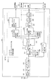
- FIG. 1 is a schematic block diagram showing the configuration of the base station apparatus 3 according to the embodiment of the present invention.
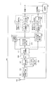
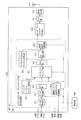
- the base station apparatus 3 includes a reception processing unit 101, a radio resource control unit 103, a control unit 105, and a transmission processing unit 107.
- the reception processing unit 101 demodulates the received PUCCH and PUSCH signals received from the mobile station apparatus 5 by the reception antenna 109 using the uplink reference signal according to the instruction of the control unit 105.
- the reception processing unit 101 decodes the demodulated signal.
- the reception processing unit 101 extracts control information and information data from the decoded signal.
- the reception processing unit 101 performs a process of extracting UCI on the uplink subframe and UL PRB in which the own device has allocated PUCCH resources to the mobile station device 5.
- the reception processing unit 101 is instructed from the control unit 105 as to what processing is to be performed for which uplink subframe and which UL PRB.
- reception processing section 101 instructs control section 105 to perform detection processing for multiplying and combining code sequences in the time domain and multiplying and combining code sequences in the frequency domain with respect to ACK / NACK PUCCH signals. Is done.
- Reception processing section 101 is instructed by control section 105 to use a frequency-domain code sequence and / or a time-domain code sequence used for processing to detect UCI from PUCCH.
- the reception processing unit 101 outputs the extracted UCI to the control unit 105 and outputs information data to the upper layer.
- the reception processing unit 101 detects (receives) a preamble sequence from the PRACH reception signal received from the mobile station apparatus 5 by the reception antenna 109 in accordance with an instruction from the control unit 105.
- the reception processing unit 101 also estimates arrival timing along with detection of the preamble sequence.
- the reception processing unit 101 performs processing for detecting a preamble sequence for the uplink subframe and UL PRB to which the device itself has assigned PRACH resources.
- the reception processing unit 101 is a preamble sequence that is not used in the contention based random access procedure, and that is not assigned as a Dedicated preamble to any mobile station apparatus 5, and is received by the PRACH signal. Therefore, it is possible not to perform processing such as detection of whether or not the preamble sequence has been transmitted and estimation of arrival timing. Details of the reception processing unit 101 will be described later.
- the radio resource control unit 103 allocates resources for PRACH (uplink subframe and UL PRB), allocated dedicated preamble, allocates resources to PDCCH, allocates resources to PUCCH, allocates DL PRB to PDSCH, UL PRB to PUSCH Allocation, various channel modulation schemes, coding rates, transmission power control values, and the like. Radio resource control section 103 also sets a frequency domain code sequence, a time domain code sequence, and the like for PUCCH. Also, the radio resource control unit 103 outputs information indicating the set Dedicated preamble assignment to the control unit 105. Part of the information set by the radio resource control unit 103 is notified to the mobile station device 5 via the transmission processing unit 107. For example, the mobile station apparatus 5 is notified of information indicating Dedicated preamble allocation and information indicating resource allocation to the PRACH.
- PRACH uplink subframe and UL PRB
- the radio resource control unit 103 sets PDSCH radio resource allocation and the like based on the UCI acquired by the reception processing unit 101 using the PUCCH and input via the control unit 105. For example, when ACK / NACK acquired using PUCCH is input, radio resource control section 103 assigns PDSCH resources for which NACK is indicated by ACK / NACK to mobile station apparatus 5.
- the radio resource control unit 103 configures a plurality of DL CCs and a plurality of UL CCs for the mobile station device 5 when the own device performs communication using cell aggregation. Also, the radio resource control unit 103 sets PDSCH CC, PCell, and SCell associated with the PDCCH CC, PDCCH CC, for the mobile station apparatus 5.
- the radio resource control unit 103 includes information indicating which cell is set as the PCell via the transmission processing unit 107, and information indicating the DL CC associated as the PDCCH CC with respect to the PDSCH CC of each SCell. It outputs to the control part 105 so that the mobile station apparatus 5 may be notified.
- the cell connected by the mobile station device 5 in the initial connection is automatically set as PCell, (ii) SCell is added, (iii) information of the added SCell (DL CC frequency, frequency band,
- the radio resource control unit 103 may be configured to notify the mobile station device 5 of UL CC frequency, frequency band, cell index).
- the radio resource control unit 103 outputs various control signals to the control unit 105.
- the control signal is a control signal indicating the allocation of the dedicated preamble.
- the radio resource control unit 103 outputs a control signal indicating an uplink subframe and an UL PRB in which a dedicated preamble sequence and a PRACH that permits transmission of the dedicated preamble are arranged.
- control unit 105 Based on the control signal input from the radio resource control unit 103, the control unit 105 assigns a DL PRB to the PDSCH, assigns resources to the PDCCH, sets a modulation scheme for the PDSCH, sets a coding rate for the PDSCH and the PDCCH, etc. Control is performed on the transmission processing unit 107. Further, based on the control signal input from radio resource control unit 103, control unit 105 generates DCI that is transmitted using PDCCH, and outputs the generated DCI to transmission processing unit 107.
- the DCI transmitted using the PDCCH includes a downlink assignment that does not include information related to the PDCCH order, a downlink assignment that includes information related to the PDCCH order, and an uplink grant.
- control unit 105 transmits information indicating DL CC and UL CC used for communication, information indicating PCell, information indicating association between PDSCH CC and PDCCH CC, information indicating resource allocation of PRACH, and the like. Control is performed to transmit to the mobile station apparatus 5 using the PDSCH via the processing unit 107.
- the control unit 105 Based on the control signal input from the radio resource control unit 103, the control unit 105 allocates resources (uplink subframes and UL PRBs) to the PRACH, allocates dedicated preambles, allocates the UL PRB to the PUSCH, and allocates resources to the PUCCH. Control such as allocation, PUSCH and PUCCH modulation scheme setting, PUSCH coding rate setting, PUCCH detection processing, and PUCCH code sequence setting are performed on reception processing section 101. In addition, the control unit 105 receives the UCI transmitted from the mobile station apparatus 5 using the PUCCH from the reception processing unit 101. The control unit 105 outputs the input UCI to the radio resource control unit 103.
- resources uplink subframes and UL PRBs
- Control such as allocation, PUSCH and PUCCH modulation scheme setting, PUSCH coding rate setting, PUCCH detection processing, and PUCCH code sequence setting are performed on reception processing section 101.
- the control unit 105 receives the UCI transmitted from the mobile station
- the control unit 105 receives information indicating the arrival timing of the detected preamble sequence from the reception processing unit 101, and adjusts the uplink transmission timing adjustment values (TA: Timing Advance, Timing Adjustment, Timing Alignment, TA value). ) Is calculated. Information (TA command) indicating the calculated uplink transmission timing adjustment value is notified to the mobile station apparatus 5 via the transmission processing unit 107.
- the reception processing unit 101 detects (receives) a preamble sequence
- the control unit 105 When the reception processing unit 101 detects (receives) a preamble sequence, the control unit 105 generates information indicating a response to the transmission of the preamble sequence of the mobile station apparatus 5. Information indicating the generated response is transmitted to the mobile station device 5 via the transmission processing unit 107.
- Information indicating the response to the transmission of the Dedicated preamble includes information indicating an adjustment value of the uplink transmission timing.
- information indicating a response to the transmission of the Dedicated preamble includes information indicating a Random ID (also referred to as “Random Access Preamble Identifier”) corresponding to a preamble sequence, or a movement allocated in advance to the mobile station apparatus 5
- Information indicating C-RNTI Cell Radio Network Temporary Identifier which is a station device identifier is included.
- the Random ID is composed of 6 bits and is assigned in advance to each of the 64 preamble sequences. Random ID is information for identifying a preamble sequence. The relationship between the Random ID and the preamble sequence is determined as a communication system rule.
- the C-RNTI is information for identifying the mobile station apparatus 5 in which connection (RRC connection) with the base station apparatus 3 is established in a cell managed by the base station apparatus 3.
- the base station device 3 assigns C-RNTI to the mobile station device 5 when establishing a connection with the mobile station device 5.
- the control unit 105 When detecting (receiving) the Dedicated preamble in a cell that is a PCell (first type cell) for the mobile station device 5, the control unit 105 responds to the detected Dedicated preamble as a response to the reception of the preamble sequence.
- Information indicating the Random ID to be transmitted and information indicating the adjustment value of the uplink transmission timing for the PCell that has detected (received) the Dedicated preamble is controlled to be transmitted to the mobile station apparatus 5 via the transmission processing unit 107.
- Information indicating the adjustment value of the uplink transmission timing for the PCell is generated by the control unit 105.
- the control unit 105 When detecting (receiving) the Dedicated preamble in a cell that is an SCell (second type cell) for the mobile station device 5, the control unit 105 assigns the detected Dedicated preamble as a response to reception of the preamble sequence.
- Information indicating the C-RNTI allocated in advance to the device 5 and information indicating the adjustment value of the uplink transmission timing for the SCell that has detected (received) the dedicated preamble are sent to the mobile station device 5 via the transmission processing unit 107. Control to send.
- Information indicating the adjustment value of the uplink transmission timing for the SCell is generated by the control unit 105.
- a cell in which the corresponding PDCCH is arranged in another cell is set as a second type cell according to the setting of the crosscarrier scheduling.
- a cell that does not correspond to the second type is defined as a first type cell.
- As a first type of cell there are a cell to which Cross carrier scheduling is not applied, and a cell in which a PDCCH corresponding to the own cell is arranged in a different cell depending on the setting of Cross carrier scheduling.
- the control unit 105 When the Dedicated preamble is detected (received) in the cell which is the first type of cell for the mobile station device 5, the control unit 105 receives the Random ID corresponding to the detected Dedicated preamble as a response to the reception of the preamble sequence. And information indicating the adjustment value of the uplink transmission timing for the first type cell in which the Dedicated preamble has been detected (received) are transmitted to the mobile station apparatus 5 via the transmission processing unit 107. Control. Information indicating the adjustment value of the uplink transmission timing for the first type cell is generated by the control unit 105.
- the control unit 105 When the Dedicated Preamble is detected (received) in a cell that is a second type of cell for the mobile station device 5, the control unit 105 responds to reception of the preamble sequence as a response to reception of the preamble sequence to the mobile station device 5 to which the detected Dedicated preamble is assigned.
- the mobile station apparatus via the transmission processing unit 107 transmits information indicating the C-RNTI allocated in advance and information indicating the adjustment value of the uplink transmission timing for the second type cell in which the Dedicated preamble is detected (received). Control to transmit to 5.
- Information indicating the adjustment value of the uplink transmission timing for the second type cell is generated by the control unit 105.
- the control unit 105 when detecting (receiving) the Dedicated preamble in the uplink of the cell which is the first type cell, the control unit 105, as a response to the reception of the preamble sequence, (i) RA-RNTI (Random The transmission processing unit 107 is controlled to transmit information indicating Access-Radio Network Temporary Identifier (random access response identifier) on the downlink PDCCH of the first type cell, and (ii) detected (received) Dedicated.
- RA-RNTI Random access response identifier
- the information indicating the Random ID corresponding to the preamble and the information indicating the adjustment value of the uplink transmission timing for the first type cell that has detected (received) the Dedicated preamble, and the downlink PDSCH of the first type cell Send process to send in The unit 107 is controlled.
- the information indicating the resource allocation of the PDSCH is included in the PDCCH including information indicating the RA-RNTI.
- RA-RNTI corresponds to PRACH.
- the RA-RNTI indicates which random access response corresponding to which PRACH is included in the PDSCH information in which resource allocation is indicated by the PDCCH.
- the RA-RNTI is associated with, for example, the number of the uplink subframe in which the PRACH is arranged.
- a signal obtained by modulating (information) is transmitted on the PDCCH.
- the control unit 105 When the Dedicated Preamble is detected (received) in the uplink of the cell which is the second type cell, the control unit 105, as a response to the reception of the preamble sequence, (i) the mobile station apparatus 5 to which the detected Dedicated preamble is allocated
- the transmission processing unit 107 is controlled to transmit the information indicating the C-RNTI allocated in advance to the downlink PDCCH of the first type cell, and (ii) Dedicated preamble is detected (received).
- the transmission processing unit 107 is controlled so that information indicating the adjustment value of the uplink transmission timing for the two types of cells is transmitted on the downlink PDSCH of the first type cell or the second type cell. .
- the information indicating the resource allocation of the PDSCH is included in the PDCCH including information indicating the C-RNTI.
- a signal obtained by modulating (information) is transmitted on the PDCCH.
- the transmission processing unit 107 generates a signal to be transmitted using the PDCCH and PDSCH based on the control signal input from the control unit 105, and transmits the generated signal via the transmission antenna 111.
- the transmission processing unit 107 is input from the radio resource control unit 103, information indicating DL CC and UL CC used for communication using cell aggregation, information indicating PCell, information indicating correspondence between PDSCH CC and PDCCH CC , Information indicating the PRACH resource, information data input from an upper layer, and the like are transmitted to the mobile station apparatus 5 using the PDSCH. Also, the transmission processing unit 107 transmits DCI (information on PDCCH order) input from the control unit 105 to the mobile station apparatus 5 using the PDCCH.
- DCI information on PDCCH order
- the transmission process part 107 transmits the response with respect to reception of the preamble series produced
- the information data is assumed to include information on several types of control. Details of the transmission processing unit 107 will be described later.
- FIG. 2 is a schematic block diagram showing the configuration of the transmission processing unit 107 of the base station apparatus 3 according to the embodiment of the present invention.
- the transmission processing unit 107 includes a plurality of physical downlink shared channel processing units 201-1 to 201-M, a plurality of physical downlink control channel processing units 203-1 to 203-M, downlink pilots.
- Channel processing unit 205 multiplexing unit 207, IFFT (Inverse Fast Fourier Transform) unit 209, GI (Guard Interval) insertion unit 211, D / A (Digital / Analog converter) unit 213, a transmission RF (Radio Frequency) unit 215, and a transmission antenna 111.
- IFFT Inverse Fast Fourier Transform
- GI Guard Interval
- D / A Digital / Analog converter
- transmission RF Radio Frequency unit 215, and a transmission antenna 111.
- the physical downlink shared channel processing units 201-1 to 201-M are collectively referred to as “physical downlink shared channel processing unit 201”.
- the physical downlink control channel processing units 203-1 to 203-M are collectively referred to as “physical downlink control channel processing unit 203”.
- each physical downlink shared channel processing unit 201 and each physical downlink control channel processing unit 203 have the same configuration and function, only one of them will be described as a representative. Although the case where the number of transmission antennas is one will be described here, a plurality of transmission antennas may be configured.
- the physical downlink shared channel processing unit 201 includes a turbo coding unit 219 and a data modulation unit 221, respectively.
- the physical downlink control channel processing unit 203 includes a convolutional coding unit 223 and a QPSK modulation unit 225.
- the physical downlink shared channel processing unit 201 performs baseband signal processing for transmitting information data to the mobile station apparatus 5 by the OFDM method.
- the turbo encoding unit 219 performs turbo encoding on the input information data at the encoding rate input from the control unit 105 in order to increase data error tolerance.
- the turbo encoder 219 outputs the turbo encoded information data to the data modulator 221.
- the data modulation unit 221 uses the modulation scheme (for example, QPSK (Quadrature Phase Shift Keying), 16QAM (16-value quadrature amplitude modulation) inputted from the control unit 105 to the data encoded by the turbo encoding unit 219. Modulation with 16 Quadrature Amplitude Modulation, 64QAM (64-value quadrature amplitude modulation; 64 Quadrature Amplitude Modulation) to generate a signal sequence of modulation symbols.
- the data modulation unit 221 outputs the generated signal sequence to the multiplexing unit 207.
- the physical downlink control channel processing unit 203 performs baseband signal processing for transmitting the DCI input from the control unit 105 in the OFDM scheme.
- the convolutional coding unit 223 performs convolutional coding for increasing DCI error tolerance based on the coding rate input from the control unit 105.
- DCI is controlled in bit units.
- the convolutional coding unit 223 also performs rate matching to adjust the number of output bits for the bits subjected to the convolutional coding process based on the coding rate input from the control unit 105.
- the convolutional coding unit 223 outputs the encoded DCI to the QPSK modulation unit 225.
- the QPSK modulation unit 225 modulates the DCI encoded by the convolutional coding unit 223 using the QPSK modulation method, and outputs the modulated modulation symbol signal sequence to the multiplexing unit 207.
- the downlink pilot channel processing unit 205 generates a downlink reference signal (also referred to as a Cell specific RS) that is a known signal in the mobile station device 5 and outputs the downlink reference signal to the multiplexing unit 207.
- a downlink reference signal also referred to as a Cell specific RS
- Multiplexer 207 receives a signal input from downlink pilot channel processor 205, a signal input from each physical downlink shared channel processor 201, and a signal input from each physical downlink control channel processor 203. Are multiplexed into the downlink subframe according to the instruction from the control unit 105. Control signals related to the allocation of DL PRBs to the PDSCH set by the radio resource control unit 103 and the allocation of resources to the PDCCH are input to the control unit 105, and the control unit 105 controls the processing of the multiplexing unit 207 based on the control signal. To do.
- the multiplexing unit 207 performs multiplexing of PDSCH and PDCCH basically by time multiplexing as shown in FIG. Multiplexer 207 performs multiplexing between the downlink pilot channel and other channels by time and frequency multiplexing. Further, the multiplexing unit 207 multiplexes PDSCH addressed to each mobile station device 5 in units of DL PRB pairs. Multiplexer 207 may multiplex PDSCH for one mobile station apparatus 5 using a plurality of DL PRB pairs. Further, the multiplexing unit 207 performs multiplexing of the PDCCH addressed to each mobile station device 5 using resources in the same DL CC. The multiplexing unit 207 outputs the multiplexed signal to the IFFT unit 209.
- the IFFT unit 209 performs fast inverse Fourier transform on the signal multiplexed by the multiplexing unit 207.
- the IFFT unit 209 performs OFDM modulation on the fast inverse Fourier transformed signal and outputs it to the GI insertion unit 211.
- the GI insertion unit 211 generates a baseband digital signal including symbols in the OFDM scheme by adding a guard interval to the signal modulated by the OFDM scheme by the IFFT unit 209. As is well known, the guard interval is generated by duplicating a part of the head or tail of the OFDM symbol to be transmitted.
- the GI insertion unit 211 outputs the generated baseband digital signal to the D / A unit 213.
- the D / A unit 213 converts the baseband digital signal input from the GI insertion unit 211 into an analog signal and outputs the analog signal to the transmission RF unit 215.
- the transmission RF unit 215 generates an in-phase component and a quadrature component of the intermediate frequency from the analog signal input from the D / A unit 213. Further, the transmission RF unit 215 removes excess frequency components for the intermediate frequency band. Next, the transmission RF unit 215 converts (up-converts) the intermediate frequency signal into a high frequency signal. The transmission RF unit 215 removes excess frequency components from the converted high frequency signal.
- the transmission RF unit 215 power-amplifies the signal from which the extra frequency component has been removed, and transmits the power-amplified signal to the mobile station apparatus 5 via the transmission antenna 111.
- FIG. 3 is a schematic block diagram showing the configuration of the reception processing unit 101 of the base station apparatus 3 according to the embodiment of the present invention.
- the reception processing unit 101 includes a reception RF unit 301, an A / D (Analog / Digital converter) unit 303, a component carrier separation unit 305, and a plurality of uplink component carrier reception processes.
- the units 307-1 to 307-M are included. Also, as shown in FIG.
- the reception processing unit 307 for each uplink component carrier includes a symbol timing detection unit 309, a GI removal unit 311, an FFT unit 313, a subcarrier demapping unit 315, a channel estimation unit 317, and a PUSCH.
- the reception processing units 307-1 to 307-M for each uplink component carrier are expressed as “reception processing unit 307 for each uplink component carrier”. Since each uplink component carrier reception processing unit 307 has the same configuration and function, only one of them will be described as a representative.
- the reception RF unit 301 (i) appropriately amplifies the signal received by the reception antenna 109, (ii) converts the amplified signal into an intermediate frequency signal (down-conversion), and (iii) after the conversion (Iv) control the amplification level so that the signal level of the signal from which the unnecessary frequency component is removed is properly maintained, and (v) the in-phase component of the received signal. Based on the quadrature component, the signal whose amplification level is controlled is quadrature demodulated. The reception RF unit 301 outputs the quadrature demodulated analog signal to the A / D unit 303.
- the A / D unit 303 converts the analog signal quadrature demodulated by the reception RF unit 301 into a digital signal, and outputs the converted digital signal to the component carrier separation unit 305.
- the component carrier separation unit 305 separates the reception signal for each UL CC of the uplink system bandwidth, and outputs it to the reception processing unit 307 for each uplink component carrier.
- the uplink component carrier reception processing unit 307 performs demodulation and decoding of PUSCH and PUCCH in the UL CC, and detects information data and UCI.
- the symbol timing detection unit 309 detects the symbol timing based on the signal input from the component carrier separation unit 305.
- the symbol timing detection unit 309 outputs a control signal indicating the timing of the detected symbol boundary to the GI removal unit 311.
- the GI removal unit 311 removes the portion corresponding to the guard interval from the signal input from the component carrier separation unit 305, and sends the remaining signal to the FFT unit 313.
- the FFT unit 313 performs fast Fourier transform on the signal input from the GI removal unit 311.
- the FFT unit 313 performs DFT-Spread-OFDM demodulation on the signal obtained by the fast Fourier transform. Further, FFT section 313 outputs the demodulated signal to subcarrier demapping section 315. Note that the number of points in the FFT unit 313 is equal to the number of points in the IFFT unit of the mobile station apparatus 5 described later.
- subcarrier demapping section 315 Based on the control signal input from control section 105, subcarrier demapping section 315 converts the signal demodulated by FFT section 313 into an uplink reference signal for an uplink pilot channel, a PUSCH signal, and a PUCCH signal. To separate.
- the subcarrier demapping section 315 outputs the separated uplink reference signal to the propagation path estimation section 317, outputs the separated PUSCH signal to the PUSCH propagation path equalization section 319, and outputs the separated PUCCH signal to the PUCCH To the propagation path equalization unit 321 for use.
- the propagation path estimation unit 317 estimates propagation path fluctuations using the uplink reference signal separated by the subcarrier demapping unit 315 and the known signal.
- the propagation path estimation unit 317 outputs the estimated propagation path estimation value to the PUSCH propagation path equalization unit 319 and the PUCCH propagation path equalization unit 321.
- the PUSCH channel equalization unit 319 equalizes the amplitude and phase of the PUSCH signal separated by the subcarrier demapping unit 315 based on the channel estimation value input from the channel estimation unit 317.
- “equalization” refers to a process of restoring the fluctuation of the propagation path received by the signal during wireless communication.
- PUSCH propagation path equalization section 319 outputs the adjusted signal to IDFT section 323.
- the IDFT unit 323 performs discrete inverse Fourier transform on the signal input from the PUSCH channel equalization unit 319 and outputs a signal obtained by the discrete inverse Fourier transform to the data demodulation unit 325.
- the data demodulation unit 325 demodulates the PUSCH signal converted by the IDFT unit 323, and outputs the demodulated PUSCH signal to the turbo decoding unit 327.
- This demodulation is demodulation corresponding to the modulation method used in the data modulation unit of the mobile station apparatus 5, and the modulation method is input from the control unit 105.
- the turbo decoding unit 327 decodes information data from the PUSCH signal input from the data demodulation unit 325 and demodulated.
- the coding rate is input from the control unit 105.
- the PUCCH channel equalization unit 321 equalizes the amplitude and phase of the PUCCH signal separated by the subcarrier demapping unit 315 based on the channel estimation value input from the channel estimation unit 317.
- the PUCCH channel equalization unit 321 outputs the equalized signal to the physical uplink control channel detection unit 329.
- the physical uplink control channel detection unit 329 demodulates the signal input from the PUCCH channel equalization unit 321 and decodes the demodulated signal.
- the physical uplink control channel detection unit 329 detects UCI from the decoded signal.
- the physical uplink control channel detection unit 329 performs processing for separating the frequency domain and / or the signal code-multiplexed in the frequency domain.
- the physical uplink control channel detection unit 329 detects ACK / NACK, SR, and CQI from the PUCCH signal code-multiplexed in the frequency domain and / or time domain using the code sequence used on the transmission side. Process.
- the physical uplink control channel detection unit 329 performs a detection process using a code sequence in the frequency domain, that is, a process for separating a code-multiplexed signal in the frequency domain, for each PUCCH subcarrier signal. On the other hand, each code of the code sequence is multiplied.
- the physical uplink control channel detection unit 329 combines the signals multiplied by the respective codes after the multiplication.
- the physical uplink control channel detection unit 329 performs detection processing using a code sequence in the time domain, that is, processing for separating code-multiplexed signals in the time domain, for each SC-FDMA symbol of PUCCH. Is multiplied by each code of the code sequence.
- the physical uplink control channel detection unit 329 combines the signals multiplied by the respective codes after the multiplication.
- the physical uplink control channel detection unit 329 sets detection processing for the PUCCH signal based on the control signal from the control unit 105.
- the preamble detection unit 331 performs processing for detecting (receiving) a preamble transmitted for a reception signal corresponding to the PRACH based on the signal input from the component carrier separation unit 305. Specifically, the preamble detection unit 331 performs correlation processing on a received signal at various timings within the guard time with a replica signal generated using each preamble sequence that may be transmitted. . For example, if the correlation value is higher than a preset threshold value, the preamble detection unit 331 receives from the mobile station device 5 the same signal as the preamble sequence used to generate the replica signal used for the correlation processing. Judge that it was sent. The preamble detection unit 331 determines that the timing with the highest correlation value is the arrival timing of the preamble sequence. The preamble detection unit 331 generates preamble detection information including at least information indicating the detected preamble sequence and information indicating arrival timing, and outputs the preamble detection information to the control unit 105.
- the control unit 105 includes a subcarrier demapping unit 315, a data demodulation unit, based on control information (DCI) transmitted from the base station device 3 to the mobile station device 5 using PDCCH and control information transmitted using PUSCH. 325, turbo decoding section 327, propagation path estimation section 317, and physical uplink control channel detection section 329 are controlled.
- the control unit 105 determines which resource (including PRACCH, PUSCH, and PUCCH) each mobile station device 5 has transmitted (may have transmitted) based on the control information transmitted from the base station device 3 to the mobile station device 5. It is understood whether it is composed of uplink subframes, UL PRBs, preamble sequences, frequency domain code sequences, and time domain code sequences.
- FIG. 4 is a schematic block diagram showing the configuration of the mobile station apparatus 5 according to the embodiment of the present invention.
- the mobile station apparatus 5 includes a reception processing unit 401, a radio resource control unit 403, a control unit 405, and a transmission processing unit 407 (transmission unit).
- the control unit 405 includes a random access procedure determination unit 4051.
- the reception processing unit 401 receives a signal from the base station device 3.
- the reception processing unit 401 demodulates the received signal and decodes the demodulated signal according to the instruction of the control unit 405.
- the reception processing unit 401 detects a PDCCH signal addressed to itself, the reception processing unit 401 outputs DCI obtained by decoding the PDCCH signal to the control unit 405.
- the reception processing unit 401 outputs, to the control unit 405, control information related to the allocation of the dedicated preamble included in the PDCCH.
- the reception processing unit 401 receives, via the control unit 405, information data obtained by decoding the PDSCH addressed to itself based on an instruction from the control unit 405 after outputting the DCI included in the PDCCH to the control unit 405.
- a downlink assignment that does not include information related to Dedicated preamble allocation includes information indicating PDSCH resource allocation.
- the reception processing unit 401 outputs the control information generated by the radio resource control unit 103 of the base station apparatus 3 obtained by decoding the PDSCH to the control unit 405.
- the reception processing unit 401 outputs the radio resource control unit 403 of its own device via the control unit 405.
- the control information generated by the radio resource control unit 103 of the base station apparatus 3 includes information indicating PCell, information indicating association between PDSCH CC and PDCCH CC, and information indicating resource allocation of PRACH.
- the reception processing unit 401 outputs a cyclic redundancy check (CRC) code included in the PDSCH to the control unit 405.
- CRC cyclic redundancy check
- the transmission processing unit 107 of the base station apparatus 3 generates a CRC code from the information data, and transmits the information data and the CRC code by PDSCH.
- the CRC code is used to determine whether the data included in the PDSCH is incorrect or not. If the information generated from the data using the predetermined generator polynomial and the CRC code are the same, it is determined that the data is not erroneous, and the information generated from the data using the predetermined generator polynomial and the CRC code Is different, it is determined that the data is incorrect.
- the reception processing unit 401 receives a response to the transmission of the Dedicated preamble based on an instruction from the control unit 405. For example, the reception processing unit 401 receives information indicating RA-RNTI corresponding to the PRACH used for transmission of the Dedicated preamble on the PDCCH of the first type cell. In addition, the reception processing unit 401 receives information indicating the Random ID corresponding to the transmitted Dedicated preamble and information indicating the adjustment value of the uplink transmission timing for the first type cell transmitting the Dedicated preamble. Is received on the PDSCH of the cell of the type.
- the reception processing unit 401 receives the information indicating the C-RNTI allocated in advance to the own device on the PDCCH of the first type cell, and transmits the uplink to the second type cell that has transmitted the Dedicated preamble. Information indicating the timing adjustment value is received on the PDSCH of the first type cell or the second type cell. Details of the reception processing unit 401 will be described later.
- the control unit 405 includes a random access procedure determination unit 4051.
- the control unit 405 confirms the data transmitted from the base station apparatus 3 using the PDSCH and input from the reception processing unit 401.
- the control unit 405 outputs information data in the data to the upper layer.
- the control unit 405 controls the reception processing unit 401 and the transmission processing unit 407 based on the control information generated by the radio resource control unit 103 of the base station apparatus 3 in the data. Further, the control unit 405 controls the reception processing unit 401 and the transmission processing unit 407 based on an instruction from the radio resource control unit 403.
- control unit 405 controls the reception processing unit 401 and the transmission processing unit 407 based on the DCI transmitted from the base station apparatus 3 using the PDCCH and input from the reception processing unit 401. Specifically, the control unit 405 controls the transmission processing unit 407 based on the detected downlink assignment including information regarding the allocation of the dedicated preamble. Specifically, the control unit 405 controls the reception processing unit 401 based on (i) the detected downlink assignment that does not include information regarding the dedicated preamble allocation, and (ii) the detected uplink grant. Based on the above, the transmission processing unit 407 is controlled. Also, the control unit 405 compares the data input from the reception processing unit 401 with the CRC code input from the reception processing unit 401 using a predetermined generator polynomial.
- control unit 405 determines whether the data is incorrect, and generates ACK / NACK based on the determination result. Further, the control unit 405 generates SR and CQI based on an instruction from the radio resource control unit 403. Further, the control unit 405 controls the transmission timing of the signal of the transmission processing unit 407 based on the adjustment value of the uplink transmission timing notified from the base station apparatus 3. Details of adjustment of uplink transmission timing will be described later.
- the control unit 405 controls the transmission processing unit 407 to transmit the Dedicated preamble in the PCell (first type cell)
- the control unit 405 indicates the Random ID corresponding to the transmitted Dedicated preamble as a response to the transmission of the preamble sequence.
- the reception processing unit 401 is controlled so that the base station apparatus 3 receives the information and the information indicating the adjustment value of the uplink transmission timing for the PCell that has transmitted the Dedicated preamble.
- the control unit 405 controls the transmission processing unit 407 to transmit the Dedicated preamble in the SCell (second type cell)
- the control unit 405 receives the C-RNTI assigned to the own device as a response to the transmission of the preamble sequence.
- the reception processing unit 401 is controlled so that the base station device 3 receives the information indicating the information indicating the uplink transmission timing adjustment value for the SCell that has transmitted the Dedicated preamble.
- a cell in which the PDCCH corresponding to the own cell is arranged in another cell according to the setting of the cross carrier scheduling is referred to as a “second type cell”.
- a cell not corresponding to the second type is referred to as a “first type cell”. That is, a cell in which the PDCCH corresponding to the own cell is not arranged in another cell is referred to as a “first type cell”.
- As a first type cell there are a cell to which Cross carrier scheduling is not applied, and a cell in which PDCCH corresponding to another cell is arranged in the own cell by setting Cross carrier scheduling.
- the reception processing unit 401 is controlled so that the base station apparatus 3 receives information indicating the adjustment value of the uplink transmission timing for the first type cell that has transmitted the Dedicated preamble.
- the reception processing unit 401 is controlled so that the base station apparatus 3 receives information indicating the adjustment value of the uplink transmission timing for the second type cell that has transmitted the Dedicated preamble.
- the control unit 405 controls the transmission processing unit 407 to transmit the Dedicated preamble on the uplink of the cell which is the first type cell
- the control unit 405 returns the RA- as a response to the transmission of the preamble sequence.
- the reception processing unit 401 is controlled to receive information indicating the RNTI on the downlink PDCCH of the first type cell, and the information indicating the Random ID corresponding to the transmitted Dedicated preamble and the Dedicated preamble transmitted.
- the reception processing unit 401 is controlled to receive information indicating the adjustment value of the uplink transmission timing for one type of cell on the downlink PDSCH of the first type cell.
- the information indicating the resource allocation of the PDSCH is included in the PDCCH including information indicating the RA-RNTI.
- the control unit 405 controls the transmission processing unit 407 to transmit the Dedicated preamble on the uplink of the cell that is the second type cell
- the control unit 405 responds to the transmission of the preamble sequence as a response to the C assigned in advance to the own device.
- -Control of the reception processing unit 401 so as to receive information indicating the RNTI on the downlink PDCCH of the first type cell, and adjust the uplink transmission timing for the second type cell that has transmitted the Dedicated preamble
- the reception processing unit 401 is controlled to receive the information indicating the value on the downlink PDSCH of the first type cell or the second type cell.
- the information indicating the resource allocation of the PDSCH is included in the PDCCH including information indicating the C-RNTI.
- the random access procedure determination unit 4051 determines the execution, re-execution, and termination of the non-contention based Random Access procedure, and controls related processing.
- the random access procedure determination unit 4051 when information related to Dedicated preamble allocation (by the PDCCH order) is input to the control unit 405, based on the input information, the PCell (first type cell) or SCell (first cell) It is determined that the Non-contention based Random Access procedure is executed in the second type cell).
- the random access procedure determination unit 4051 receives information indicating the identifier (Random ID) corresponding to the transmitted Dedicated preamble as a response to the Dedicated preamble transmission, and the Dedicated preamble.
- the random access procedure determination unit 4051 sends a mobile station apparatus identifier (C-RNTI) pre-assigned to the mobile station apparatus 5 as a response to the transmission of the Dedicated preamble. And the information indicating the adjustment value of the uplink transmission timing for the SCell that transmitted the Dedicated preamble from the base station device 3 via the reception processing unit 401, the Non-contention based Random Access procedure is terminated. to decide.
- C-RNTI mobile station apparatus identifier
- Non-contention based Random Access procedure is determined to be re-executed.
- a cell in which the corresponding PDCCH is arranged in another cell according to the setting of cross carrier scheduling is referred to as a “second type cell”.
- a cell not corresponding to the second type is referred to as a “first type cell”. That is, a cell in which the corresponding PDCCH is not arranged in another cell is referred to as a “first type cell”.
- As a first type cell there are a cell to which Cross carrier scheduling is not applied, and a cell in which PDCCH corresponding to another cell is arranged in the own cell by setting Cross carrier scheduling.
- the random access procedure determination unit 4051 indicates an identifier (Random ID) corresponding to the transmitted Dedicated preamble as a response to the Dedicated preamble transmission when the mobile station apparatus 5 transmits the Dedicated preamble in the first type cell.
- an identifier (Random ID) corresponding to the transmitted Dedicated preamble as a response to the Dedicated preamble transmission when the mobile station apparatus 5 transmits the Dedicated preamble in the first type cell.
- the Non-contention based Random Access procedure Is determined to end.
- the information indicating the identifier (Random ID) corresponding to the transmitted Dedicated preamble and the information indicating the adjustment value of the uplink transmission timing for the first type cell transmitting the Dedicated preamble are the first type. Received in the DL CC of the next cell.
- the random access procedure determination unit 4051 When the own mobile station device 5 transmits the Dedicated preamble in the second type cell, the random access procedure determination unit 4051 has a mobile station device identifier assigned to the own mobile station device 5 in advance as a response to the transmission of the Dedicated preamble.
- the random access procedure determination unit 4051 When receiving the information indicating (C-RNTI) and the information indicating the adjustment value of the uplink transmission timing for the second type cell transmitting the Dedicated preamble from the base station device 3 via the reception processing unit 401, It is determined that the Non-contention based Random Access procedure is finished.
- the information indicating the mobile station apparatus identifier (C-RNTI) pre-assigned to the own mobile station apparatus 5 is received in the DL CC of the first type cell, and the second type cell that has transmitted the Dedicated preamble.
- the information indicating the adjustment value of the uplink transmission timing for the first type cell or the second type cell DL CC is received.
- to which cell the information is transmitted is indicated by a carrier indicator included in the PDCCH.
- the random access procedure determination unit 4051 bases a response to the transmission of the Dedicated preamble during a predetermined period after the mobile station apparatus 5 transmits the Dedicated preamble in the first type cell or the second type cell. If it is not received from the station apparatus 3 via the reception processing unit 401, it is determined to re-execute the Non-contention based Random Access procedure in the cell that has transmitted the Dedicated preamble.
- the process “reception” appropriately includes the same meaning as the process “detection”.
- the meaning of the process “received” may mean that the received signal is demodulated and decoded and the target information is detected.
- the detection of irrelevant information (for example, information related to another mobile station device 5 and not related to the own mobile station device 5) appropriately corresponds to the meaning of the process “received” in the above description. It should be considered not included.
- parameters related to transmission power parameters specific to cells and mobile station apparatuses are notified from the base station apparatus 3 using PDSCH, and transmission power control commands are notified from the base station apparatus 3 using PDCCH.
- the transmission power control command for PUSCH is included in the uplink grant
- the transmission power control command for PUCCH is included in the downlink assignment.
- the control unit 405 controls the signal configuration of the PUCCH according to the type of UCI transmitted.
- the radio resource control unit 403 is generated by the radio resource control unit 103 of the base station device 3.
- the radio resource control unit 403 stores and holds the control information notified from the base station device 3.
- the radio resource control unit 403 controls the reception processing unit 401 and the transmission processing unit 407 via the control unit 405. That is, the radio resource control unit 403 has a memory function for holding various parameters.
- the transmission processing unit 407 transmits a signal obtained by encoding and modulating information data and UCI to the base station apparatus 3 via the transmission antenna 411 using PUSCH and PUCCH resources in accordance with instructions from the control unit 405. Also, the transmission processing unit 407 transmits the Dedicated preamble to the base station apparatus 3 using the PRACH resource according to the instruction of the control unit 405. Also, the transmission processing unit 407 sets PUSCH and PUCCH transmission power in accordance with instructions from the control unit 405. In addition, the transmission processing unit 407 controls signal transmission timing in accordance with an instruction from the control unit 405. Details of the transmission processing unit 407 will be described later.
- FIG. 5 is a schematic block diagram showing the configuration of the reception processing unit 401 of the mobile station apparatus 5 according to the embodiment of the present invention. As illustrated in FIG.
- the reception processing unit 401 includes a reception RF unit 501, an A / D unit 503, a symbol timing detection unit 505, a GI removal unit 507, an FFT unit 509, a demultiplexing unit 511, a propagation path estimation unit 513, A PDSCH channel compensation unit 515, a physical downlink shared channel decoding unit 517, a PDCCH channel compensation unit 519, and a physical downlink control channel decoding unit 521 are configured.
- the physical downlink shared channel decoding unit 517 includes a data demodulation unit 523 and a turbo decoding unit 525. As shown in FIG.
- the physical downlink control channel decoding unit 521 includes a QPSK demodulation unit 527 and a Viterbi decoder unit 529.
- the reception processing unit 401 has one reception antenna 409 is shown, but a plurality of reception antennas may be configured.
- the reception RF unit 501 appropriately (i) amplifies the signal received by the reception antenna 409, (ii) converts the amplified signal into an intermediate frequency signal (down-conversion), and (iii) the converted signal. Remove unnecessary frequency components from the signal, (iv) control the amplification level so that the signal level of the signal from which unnecessary frequency components are removed is properly maintained, and (v) in-phase component and quadrature of the received signal Based on the component, the signal whose amplification level is controlled is orthogonally demodulated.
- the reception RF unit 501 outputs the quadrature demodulated analog signal to the A / D unit 503.
- the A / D unit 503 converts the analog signal quadrature demodulated by the reception RF unit 501 into a digital signal, and outputs the converted digital signal to the symbol timing detection unit 505 and the GI removal unit 507.
- Symbol timing detection section 505 detects symbol timing based on the digital signal converted by A / D section 503, and outputs a control signal indicating the detected symbol boundary timing to GI removal section 507.
- GI removal section 507 removes the portion corresponding to the guard interval from the digital signal output from A / D section 503, and sends the remaining signal to FFT section 509. Output.
- the FFT unit 509 performs fast Fourier transform on the signal input from the GI removal unit 507.
- the FFT unit 509 performs OFDM demodulation on the signal obtained by the fast Fourier transform. Further, FFT section 509 outputs the demodulated signal to demultiplexing section 511.
- the demultiplexing unit 511 separates the signal demodulated by the FFT unit 509 into a PDCCH signal and a PDSCH signal based on the control signal input from the control unit 405.
- the demultiplexing unit 511 outputs the separated PDSCH signal to the PDSCH channel compensation unit 515.
- the demultiplexing unit 511 outputs the separated PDCCH signal to the PDCCH channel compensation unit 519.
- the demultiplexing unit 511 demultiplexes downlink resource elements in which the downlink pilot channel is arranged.
- the demultiplexing unit 511 outputs the downlink reference signal of the downlink pilot channel to the propagation path estimation unit 513.
- the demultiplexing unit 511 outputs the PDCCH CC signal to the PDCC channel compensation unit 519, and outputs the PDSCH CC signal to the PDSCH channel compensation unit 515.
- the propagation path estimation unit 513 estimates propagation path fluctuation using the downlink reference signal of the downlink pilot channel separated by the demultiplexing unit 511 and the known signal.
- the propagation path estimation unit 513 provides propagation path compensation values for adjusting the amplitude and phase so as to compensate for propagation path fluctuations, a propagation path compensation section 515 for PDSCH, a propagation path compensation section 519 for PDCCH, Output to.
- PDSCH propagation path compensation section 515 adjusts the amplitude and phase of the PDSCH signal separated by demultiplexing section 511 according to the propagation path compensation value input from propagation path estimation section 513.
- PDSCH propagation path compensation section 515 outputs the signal whose propagation path has been adjusted to data demodulation section 523 of physical downlink shared channel decoding section 517.
- the physical downlink shared channel decoding unit 517 detects information data by performing demodulation and decoding of the PDSCH based on an instruction from the control unit 405.
- the data demodulating unit 523 demodulates the PDSCH signal input from the propagation path compensating unit 515 and outputs the demodulated PDSCH signal to the turbo decoding unit 525. This demodulation is demodulation corresponding to the modulation method used in the data modulation unit 221 of the base station apparatus 3.
- the turbo decoding unit 525 decodes information data from the demodulated PDSCH signal input from the data demodulation unit 523.
- the turbo decoding unit 525 outputs the decoded information data to the upper layer via the control unit 405.
- control information and the like generated by the radio resource control unit 103 of the base station apparatus 3 transmitted using the PDSCH are also output to the control unit 405.
- the control information and the like are also output to the radio resource control unit 403 via the control unit 405.
- the CRC code included in the PDSCH is also output to the control unit 405.
- the PDCCH channel compensation unit 519 adjusts the amplitude and phase of the PDCCH signal separated by the demultiplexing unit 511 according to the channel compensation value input from the channel estimation unit 513.
- PDCCH propagation path compensation section 519 outputs the adjusted signal to QPSK demodulation section 527 of physical downlink control channel decoding section 521.
- the physical downlink control channel decoding unit 521 detects control data by demodulating and decoding the signal input from the PDCCH channel compensation unit 519 as described below.
- the QPSK demodulator 527 performs QPSK demodulation on the PDCCH signal and outputs the demodulated signal to the Viterbi decoder 529.
- the Viterbi decoder unit 529 decodes the signal demodulated by the QPSK demodulation unit 527 and outputs the decoded DCI to the control unit 405.
- this signal is expressed in bit units.
- the Viterbi decoder unit 529 also performs rate dematching in order to adjust the number of bits on which Viterbi decoding processing is performed on input bits.
- the mobile station apparatus 5 performs a process of detecting DCI addressed to itself for the PDCCH, assuming a plurality of coding rates.
- the mobile station apparatus 5 performs a different decoding process for each assumed coding rate on the PDCCH signal, whereby DCI included in the PDCCH in which no error is detected in the CRC code added to the PDCCH together with the DCI. To get.
- Such processing is referred to as “blind decoding”.
- the mobile station apparatus 5 may perform blind decoding only on signals of some resources instead of performing blind decoding on signals of all resources of the DL CC. An area of a part of the resource where coding is performed blindly is referred to as “Search space”. Further, the mobile station apparatus 5 may perform blind decoding on different resources for each coding rate.
- control unit 405 determines whether the DCI input from the Viterbi decoder unit 529 has no error. Further, the control unit 405 determines whether the input DCI is a DCI addressed to the own apparatus. When it is determined that there is no error and the DCI is addressed to itself, the control unit 405 controls the demultiplexing unit 511, the data demodulation unit 523, the turbo decoding unit 525, and the transmission processing unit 407 based on the DCI. For example, the control unit 405 controls the reception processing unit 401 to decode the PDSCH signal using the DL CC to which the resource is allocated when the DCI is a downlink assignment that does not include information regarding the Dedicated preamble.
- the control unit 405 determines whether the DCI of the PDCCH is incorrect using the CRC code. For example, when the DCI is a downlink assignment including information related to the Dedicated preamble, the control unit 405 controls the transmission processing unit 407 to transmit a PRACH signal using the allocated preamble sequence.
- FIG. 6 is a schematic block diagram showing the configuration of the transmission processing unit 407 of the mobile station apparatus 5 according to the embodiment of the present invention.
- the transmission processing unit 407 includes a plurality of uplink component carrier transmission processing units 601-1 to 601-M, a component carrier combining unit 603, a D / A unit 605, a transmission RF unit 607, and A transmission antenna 411 is included.
- the transmission processing unit 601 for each uplink component carrier includes a turbo coding unit 611, a data modulation unit 613, a DFT unit 615, an uplink pilot channel processing unit 617, and a physical uplink control channel processing unit 619.
- the mobile station apparatus 5 includes a transmission processing unit 601 for each uplink component carrier for the corresponding number of UL CCs.
- the transmission processing units 601-1 to 601-M for each uplink component carrier are collectively referred to as “transmission processing unit 601 for each uplink component carrier”. Since each uplink component carrier transmission processing section 601 has the same configuration and function, one of them will be described as a representative.
- the transmission processing unit 601 for each uplink component carrier generates a signal to be transmitted on the PRACH in the UL CC using the preamble sequence instructed from the control unit 405. Moreover, the transmission processing part 601 for every uplink component carrier adjusts the transmission power of PRACH. Moreover, the transmission processing part 601 for every uplink component carrier produces
- the turbo coding unit 611 performs turbo coding on the input information data at a coding rate instructed by the control unit 405 to increase data error tolerance.
- the turbo encoding unit 611 outputs the information data subjected to the turbo encoding to the data modulation unit 613.
- the data modulation unit 613 modulates the code data encoded by the turbo coding unit 611 with a modulation method (for example, a modulation method such as QPSK, 16QAM, or 64QAM) instructed by the control unit 405, thereby Generate a signal sequence.
- Data modulation section 613 outputs the generated modulation symbol signal sequence to DFT section 615.
- the DFT unit 615 performs a discrete Fourier transform on the signal output from the data modulation unit 613.
- the DFT unit 615 outputs the signal after the discrete Fourier transform to the subcarrier mapping unit 621.
- the physical uplink control channel processing unit 619 performs baseband signal processing for transmitting the UCI input from the control unit 405.
- the UCI input to the physical uplink control channel processing unit 619 is ACK / NACK, SR, and CQI.
- the physical uplink control channel processing unit 619 performs baseband signal processing and outputs a signal generated by the processing to the subcarrier mapping unit 621.
- the physical uplink control channel processing unit 619 encodes UCI information bits to generate a signal.
- the physical uplink control channel processing unit 619 performs signal processing related to frequency domain code multiplexing and / or time domain code multiplexing on a signal generated from UCI.
- the physical uplink control channel processing unit 619 performs control in order to realize frequency domain code multiplexing for PUCCH signals generated from ACK / NACK information bits, SR information bits, or CQI information bits.
- the physical uplink control channel processing unit 619 is instructed by the control unit 405 in order to realize time-domain code multiplexing for PUCCH signals generated from ACK / NACK information bits or SR information bits. Multiply the code sequence.
- the uplink pilot channel processing unit 617 generates an uplink reference signal that is a known signal in the base station apparatus 3 based on an instruction from the control unit 405. Uplink pilot channel processing section 617 outputs the generated uplink reference signal to subcarrier mapping section 621.
- the subcarrier mapping unit 621 converts the signal input from the uplink pilot channel processing unit 617, the signal input from the DFT unit 615, and the signal input from the physical uplink control channel processing unit 619 into the control unit 405.
- the subcarriers are arranged in subcarriers according to the instructions from, and the subcarriers in which the signals are arranged are output to IFFT section 623.
- the IFFT unit 623 performs fast inverse Fourier transform on the signal output from the subcarrier mapping unit 621, and outputs the signal after the fast inverse Fourier transform to the GI insertion unit 625.
- the number of points in the IFFT unit 623 is larger than the number of points in the DFT unit 615.
- the mobile station apparatus 5 uses the DFT unit 615, the subcarrier mapping unit 621, and the IFFT unit 623 to perform DFT-Spread-OFDM modulation on a signal transmitted using PUSCH.
- the GI insertion unit 625 adds a guard interval to the signal input from the IFFT unit 623.
- the GI insertion unit 625 outputs the signal with the guard interval added to the transmission power adjustment unit 627.
- the random access channel processing unit 629 generates a signal to be transmitted on the PRACH in the UL CC using the preamble sequence instructed by the control unit 405, and outputs the generated signal to the transmission power adjustment unit 627.
- the transmission power adjustment unit 627 adjusts the transmission power based on the control signal from the control unit 405 with respect to the signal input from the GI insertion unit 625 or the signal input from the random access channel processing unit 629, and increases the component carrier
- the data is output to the combining unit 603.
- the transmission power adjustment section 627 controls the average transmission power of the PRACH, PUSCH, PUCCH, and uplink pilot channel for each uplink subframe. For example, the transmission power adjustment unit 627 adjusts the transmission power of the PRACH so that the transmission power increases every time the preamble sequence is retransmitted.
- the component carrier combining unit 603 combines the signals for each UL CC input from the transmission processing unit 601 for each uplink component carrier, and outputs the combined signal to the D / A unit 605.
- the D / A unit 605 converts the baseband digital signal input from the component carrier combining unit 603 into an analog signal, and outputs the analog signal obtained by the conversion to the transmission RF unit 607.
- the transmission RF unit 607 generates an in-phase component and a quadrature component of the intermediate frequency from the analog signal input from the D / A unit 605. Further, the transmission RF unit 607 removes excess frequency components for the intermediate frequency band.
- the transmission RF unit 607 (i) converts (up-converts) the intermediate frequency signal into a high frequency signal, (ii) removes unnecessary frequency components from the converted signal, and (iv) extras the signal.
- the signal from which the frequency component is removed is amplified, and (v) the signal whose power amplification level is controlled is transmitted to the base station apparatus 3 via the transmission antenna 411.
- the transmission timing of the signal is controlled by the control unit 405.
- the uplink transmission timing adjustment value is configured (represented) in one of the first format (structure, type, type) and the second format (structure, type, type). Since the first format has a larger number of bits than the second format, the adjustable range of uplink transmission timing is wider than that of the second format. For example, the first format is composed of 11 bits, and the second format is composed of 6 bits.
- Ts be the minimum time unit used for adjustment of uplink transmission timing. For example, 1 / (15000 ⁇ 2048) seconds is used as Ts.
- the uplink transmission timing can be adjusted in the range of 0 ⁇ Ts to 1282 ⁇ Ts.
- the uplink transmission timing can be adjusted in the range of ( ⁇ 31) ⁇ Ts to 32 ⁇ Ts.
- the first format is used for the information indicating the uplink transmission timing adjustment value shown together with the information indicating the Random ID.
- the first format or the second format is used for the information indicating the adjustment value of the uplink transmission timing shown together with the information indicating the C-RNTI.
- the information indicating the uplink transmission timing adjustment value shown together with the information indicating the C-RNTI as a response to the transmission / reception of the preamble sequence uses the first format and is not connected as a response to the transmission / reception of the preamble sequence.
- the second format is used as the information indicating the adjustment value of the uplink transmission timing shown together with the information indicating the C-RNTI as the fine adjustment of the uplink transmission timing of the second.
- the first format is used for the adjustment value of the uplink transmission timing
- the uplink transmission timing is initially set.
- the second format is used for the adjustment value of the uplink transmission timing.
- the uplink transmission timing adjustment processing using the first format with respect to the uplink transmission timing adjustment value is based on the reference transmission timing based on the timing of the downlink time frame detected from the downlink synchronization channel.
- the transmission timing adjustment value indicated by the base station apparatus 3 is applied.
- the mobile station apparatus 5 uses a timing earlier than the reference transmission timing by [(adjustment value) ⁇ 16 ⁇ Ts] as the new transmission timing.
- the uplink transmission timing adjustment process using the second format with respect to the uplink transmission timing adjustment value is performed by adjusting the transmission timing indicated by the base station apparatus 3 with respect to the already set transmission timing. This is done by applying a value.
- the mobile station apparatus 5 uses a timing obtained by adjusting [(adjustment value) ⁇ 16 ⁇ Ts] with respect to the already set transmission timing as a new transmission timing.
- FIG. 7 is a flowchart showing an example of processing related to the non-contention based random access procedure of the mobile station apparatus 5 according to the embodiment of the present invention.
- the mobile station apparatus 5 determines whether or not the Dedicated preamble has been assigned by the PDCCH order (step S101). If the mobile station apparatus 5 determines that the Dedicated preamble has been assigned by the PDCCH order (YES in Step S101), the mobile station apparatus 5 transmits the Dedicated preamble (Step S102). If the mobile station apparatus 5 determines that the Dedicated preamble is not assigned by the PDCCH order (NO in step S101), the mobile station apparatus 5 ends the non-contention based random access procedure.
- the mobile station device 5 determines whether or not the Dedicated preamble is assigned to the first type cell (step S103). If the mobile station apparatus 5 determines that the Dedicated preamble is assigned to the first type cell (YES in step S103), the mobile station apparatus 5 indicates information (and / or RA-RNTI) indicating the Random ID corresponding to the Dedicated preamble. Information) and information indicating the adjustment value of the uplink transmission timing for the first type cell are determined during a predetermined period (step S104). If it is determined that the Dedicated preamble is not assigned to the first type cell (YES in step S103), the mobile station device 5 determines that the Dedicated preamble is assigned to the second type cell.
- step S105 whether or not the information indicating the C-RNTI allocated in advance to the own device and the information indicating the adjustment value of the uplink transmission timing for the second type cell are received during a predetermined period. Determination is made (step S105).
- step S104 the mobile station apparatus 5 indicates information indicating the Random ID corresponding to the Dedicated preamble (and / or information indicating RA-RNTI) and the adjustment value of the uplink transmission timing for the first type cell. If it is determined that the information is received during a predetermined period (YES in step S104), the non-contention based random access procedure is terminated.
- step S104 the mobile station apparatus 5 indicates information indicating the Random ID corresponding to the Dedicated preamble (and / or information indicating RA-RNTI) and the adjustment value of the uplink transmission timing for the first type cell. If it is determined that the information has not been received during the predetermined period (NO in step S104), the process returns to step S102, and the dedicated preamble is transmitted again.
- step S105 the mobile station apparatus 5 receives information indicating the C-RNTI assigned to the apparatus in advance and information indicating the adjustment value of the uplink transmission timing for the second type cell for a predetermined period. If it is determined that it has been received (YES in step S105), the non-contention based random access procedure is terminated.
- step S105 the mobile station apparatus 5 receives information indicating the C-RNTI assigned to the apparatus in advance and information indicating the adjustment value of the uplink transmission timing for the second type cell for a predetermined period. If NO in step S105, the process returns to step S102, and the Dedicated preamble is transmitted again. In addition, when the number of times of Dedicated preamble retransmission reaches a predetermined value, the mobile station apparatus 5 may end the non-contention based random access procedure.
- FIG. 8 is a flowchart showing an example of processing related to the non-contention based random access procedure of the base station apparatus 3 according to the embodiment of the present invention.
- the base station device 3 determines whether or not the Dedicated preamble has been assigned to the mobile station device 5 by the PDCCH order (step T101).
- the base station apparatus 3 executes a process of receiving (detecting) the dedicated preamble (step T102).
- the base station apparatus 3 determines whether or not the Dedicated preamble has been received (step T103). If it is determined that the Dedicated preamble has been received (YES in Step T103), the base station apparatus 3 determines whether or not the Dedicated preamble has been received in the first type cell (Step T104). If it is determined that the Dedicated preamble has not been received (NO in Step T103), the base station apparatus returns to Step T102 and executes the process of receiving the Dedicated preamble again.
- Step T104 when the base station apparatus 3 determines that the Dedicated preamble has been received in the first type cell (YES in Step T104), information (and / or RA-RNTI) indicating the Random ID corresponding to the Dedicated preamble. And information indicating the adjustment value of the uplink transmission timing for the first type cell is transmitted to the mobile station apparatus 5 (step T105).
- Step T104 when the base station apparatus 3 determines that the Dedicated preamble has not been received in the first type cell (NO in Step T104), that is, it has received the Dedicated preamble in the second type cell.
- step T106 information indicating the C-RNTI allocated in advance to the mobile station apparatus and information indicating the uplink transmission timing adjustment value for the second type cell are transmitted to the mobile station apparatus 5 (step T106). ).
- step T105 and step T106 the base station apparatus 3 ends the non-contention based random access procedure.
- the base station apparatus 3 has assigned the Dedicated preamble to the mobile station apparatus 5, if the base station apparatus 3 does not receive the Dedicated preamble during a predetermined period, the Non-contention based random access procedure is terminated.
- the base station apparatus 3 may be configured to start the non-contention based random access procedure again from the assignment of the dedicated preamble.
- the mobile station apparatus 5 is a sequence used for estimating the uplink transmission timing adjustment value (TA) in the first type cell or the second type cell.
- the (Dedicated preamble) transmission process when the Dedicated preamble is transmitted in the first type cell, the following process is performed. That is, as a response to the transmission of the Dedicated preamble, the mobile station apparatus 5 transmits information indicating the identifier (Random ID) corresponding to the Dedicated preamble (and / or information indicating the RA-RNTI) and the first that transmitted the Dedicated preamble.
- the Dedicated preamble transmission process is terminated.
- the mobile station apparatus 5 performs the following process when the Dedicated preamble is transmitted in the second type cell. That is, as a response to the transmission of the Dedicated preamble, the mobile station device 5 transmits information indicating the mobile station device identifier (C-RNTI) allocated in advance to the own device and the uplink of the second type cell that has transmitted the Dedicated preamble. When the information indicating the link transmission timing adjustment value is received from the base station apparatus 3, the Dedicated preamble transmission process is terminated.
- C-RNTI mobile station device identifier
- the mobile station apparatus 5 is an uplink for a cell (second type cell) having a large interference from another cell (a cell having a frequency band overlapping with that of the own cell, which is managed by another base station apparatus) at least in the downlink.
- the mobile station apparatus 5 can appropriately execute the dedicated preamble reassignment and re-transmission instruction to the mobile station apparatus 5 when the dedicated preamble is not detected by the base station apparatus 3. In addition, it is possible to execute Dedicated preamble resending.
- the mobile station apparatus 5 receives information indicating an adjustment value of uplink transmission timing for a cell (first type cell) in which interference from other cells is not large in the downlink, together with information indicating RA-RNTI.
- the base station apparatus 3 uses the PRACH corresponding to the same RA-RNTI to perform a non-contention based random access procedure or a contention based random access procedure to other mobile station apparatuses 5 that have executed a common PDSCH. Can be used to notify information indicating an adjustment value of uplink transmission timing. Therefore, the base station apparatus 3 can suppress the use of PDCCH, and can prevent the efficiency of the communication system from deteriorating.
- the adjustment value is configured in one of the first format and the second format.
- the first format has more bits indicating the adjustable range of uplink transmission timing than the second format.
- the first format is used when included in the response to the transmission of the Dedicated preamble, and the second format is used otherwise.
- the number of bits used to indicate the adjustment value of the uplink transmission timing can be appropriately suppressed. As a result, it is possible to prevent the efficiency of the communication system from deteriorating.
- the base station apparatus 3 uses a sequence (Dedicated preamble) used for estimating an uplink transmission timing adjustment value (TA) in the first type cell or the second type cell.
- a sequence Dedicated preamble used for estimating an uplink transmission timing adjustment value (TA) in the first type cell or the second type cell.
- the base station apparatus 3 receives, as a response to the reception of the Dedicated preamble, information indicating the identifier (Random ID) corresponding to the Dedicated preamble (and / or information indicating the RA-RNTI) and the first that has received the Dedicated preamble.
- Information indicating an adjustment value for the type cell is transmitted to the mobile station apparatus 5.
- the base station apparatus 3 When the base station apparatus 3 receives the Dedicated preamble in the second type cell in the reception process of the sequence used for the estimation of the adjustment value of the uplink transmission timing, the base station apparatus 3 performs the following process. That is, the base station apparatus 3 responds to reception of the Dedicated preamble with respect to information indicating the mobile station apparatus identifier (C-RNTI) allocated in advance to the mobile station apparatus 5 and the second type cell that has received the Dedicated preamble. Information indicating the adjustment value is transmitted to the mobile station apparatus 5.
- the adjustment value is configured in one of the first format and the second format.
- the first format has more bits indicating the adjustable range of uplink transmission timing than the second format.
- the first format is used when included in the response to the reception of the Dedicated preamble, and the second format is used otherwise.
- Cross carrier scheduling is applied.
- the mobile station apparatus 5 can appropriately execute the non-contention based random access procedure even in the cell aggregation that needs to measure the adjustment value of the uplink transmission timing in a plurality of cells.
- the mobile station device 5 is not limited to a mobile terminal, and the present invention may be realized by mounting the function of the mobile station device 5 on a fixed terminal.
- the characteristic means of the present invention described above can also be realized by mounting and controlling functions in an integrated circuit. That is, the integrated circuit of the present invention is an integrated circuit that is mounted on a mobile station device to cause the mobile station device to perform a plurality of functions, and (i) a first type cell and a second type And (ii) a sequence used for estimating an adjustment value of uplink transmission timing in the first type cell or the second type cell.
- the sequence when the sequence is transmitted in the first type cell, as a response to the transmission of the sequence, information indicating an identifier corresponding to the sequence, and the first type of cell that transmitted the sequence A function of terminating transmission processing of the sequence when receiving information indicating the adjustment value for the cell from the base station apparatus; and (iii) when transmitting the sequence in the second type cell, To send When receiving from the base station apparatus information indicating a mobile station apparatus identifier pre-assigned to the own apparatus and information indicating the adjustment value for the second type cell that has transmitted the sequence, as a response to A function of terminating the transmission process of the sequence; and (iv) if a response to the transmission of the sequence is not received from the base station apparatus during a predetermined period after transmitting the sequence, the sequence is transmitted again
- the mobile station apparatus is caused to exhibit a series of functions including a transmission processing function.
- the operation described in the embodiment of the present invention may be realized by a program.
- the program that operates in the mobile station apparatus 5 and the base station apparatus 3 related to the present invention is a program (a program that causes a computer to function) that controls the CPU and the like so as to realize the functions of the above-described embodiments related to the present invention.
- Information handled by these devices is temporarily stored in the RAM at the time of processing, then stored in various ROMs and HDDs, read out by the CPU, and corrected and written as necessary.
- a semiconductor medium for example, ROM, nonvolatile memory card, etc.
- an optical recording medium for example, DVD, MO, MD, CD, BD, etc.
- a magnetic recording medium for example, magnetic tape, Any of a flexible disk etc.
- the program when distributing to the market, can be stored and distributed on a portable recording medium, or transferred to a server computer connected via a network such as the Internet.
- the storage device of the server computer is also included in the present invention.
- LSI which is typically an integrated circuit.
- Each functional block of the mobile station device 5 and the base station device 3 may be individually chipped, or a part or all of them may be integrated into a chip.
- the method of circuit integration is not limited to LSI, and may be realized by a dedicated circuit or a general-purpose processor.
- an integrated circuit based on the technology can also be used.
- Information and signals can be presented using a variety of different techniques and methods. For example, chips, symbols, bits, signals, information, commands, instructions, and data that may be referred to throughout the above description may be indicated by voltage, current, electromagnetic waves, magnetic or magnetic particles, optical or light particles, or combinations thereof .
- DSPs digital signal processors
- ASIC Application specific integrated circuit
- FPGA field programmable gate array signal
- a general purpose processor may be a microprocessor, but in the alternative, the processor may be any conventional processor, controller, microcontroller, or state machine.
- the processor may also be implemented as a combination of computing devices. For example, a DSP and a microprocessor, a plurality of microprocessors, one or more microprocessors connected to a DSP core, or a combination of other such configurations.
- a software module may reside in RAM memory, flash memory, ROM memory, EPROM memory, EEPROM memory, registers, hard disk, removable disk, CD-ROM, or any form of recording medium known in the art.
- a typical recording medium may be coupled to the processor such that the processor can read information from, and write information to, the recording medium.
- the recording medium may be integral to the processor.
- the processor and the recording medium may be in the ASIC.
- the ASIC can be in the mobile station device (user terminal). Or a processor and a recording medium may exist in a mobile station apparatus as a discrete element.
- the functions described can be implemented in hardware, software, firmware, or a combination thereof. If implemented by software, the functions may be maintained or transmitted as one or more instructions or code on a computer-readable medium.
- Computer-readable media includes both communication media and computer recording media including media that facilitate carrying a computer program from one place to another.
- the recording medium may be any commercially available medium that can be accessed by a general purpose or special purpose computer.
- such computer readable media may be RAM, ROM, EEPROM, CDROM or other optical disc media, magnetic disc media or other magnetic recording media, or general purpose or It can include media that can be accessed by a special purpose computer or general purpose or special purpose processor and used to carry or retain the desired program code means in the form of instructions or data structures.
- any connection is also properly termed a computer-readable medium.
- the software uses a coaxial cable, fiber optic cable, twisted pair, digital subscriber line (DSL), or wireless technology such as infrared, wireless, or microwave
- a website, server, or other remote source When transmitting from, these coaxial cables, fiber optic cables, twisted pair, DSL, or wireless technologies such as infrared, wireless, and microwave are included in the definition of the medium.
- the discs (disk, disc) used in the present specification include compact discs (CD), laser discs (registered trademark), optical discs, digital versatile discs (DVD), floppy (registered trademark) discs, and Blu-ray discs.
- the disk generally reproduces data magnetically, while the disk optically reproduces data with a laser. Combinations of the above should also be included on the computer-readable medium.
- 3 base station device 5 (A to C) mobile station device, 101 reception processing unit, 103 radio resource control unit, 105 control unit, 107 transmission processing unit, 109 reception antenna, 111 transmission antenna, 201 physical downlink shared channel processing Unit, 203 physical downlink control channel processing unit, 205 downlink pilot channel processing unit, 207 multiplexing unit, 209 IFFT unit, 211 GI insertion unit, 213 D / A unit, 215 transmission RF unit, 219 turbo coding unit, 221 data Modulation unit, 223 convolutional code unit, 225 QPSK modulation unit, 301 reception RF unit, 303 A / D unit, 305 component carrier separation unit, 307 uplink component carrier reception processing unit, 309 symbol timing detection unit, 311 GI removal 313 FFT section, 315 subcarrier demapping section, 317 propagation path estimation section, 319 propagation path equalization section (for PUSCH), 321 propagation path equalization section (for PUCCH), 323 IDFT section, 325 data demodulation section,
Landscapes
- Engineering & Computer Science (AREA)
- Signal Processing (AREA)
- Computer Networks & Wireless Communication (AREA)
- Mobile Radio Communication Systems (AREA)
Abstract
複数の移動局装置と基地局装置とから構成される通信システムにおいて、複数の上りリンクの周波数帯域に対して上りリンクの送信タイミングの設定手順が効率的に実行されることを可能にする。第一のタイプのセルまたは第二のタイプのセルでの上りリンクの送信タイミングの調整値の推定に用いられる系列の送信処理において、移動局装置は、第一のタイプのセルで系列を送信した場合、系列の送信に対する応答として、系列に対応する識別子を示す情報と、系列を送信した第一のタイプのセルに対する調整値を示す情報とを受信したら、系列の送信処理を終了する。移動局装置は、第二のタイプのセルで系列を送信した場合、系列の送信に対する応答として、自装置に予め割り当てられた移動局装置識別子を示す情報と、系列を送信した第二のタイプのセルに対する調整値を示す情報とを受信したら、系列の送信処理を終了する。移動局装置は、系列を送信してから所定の期間の間に、系列の送信に対する応答を受信しなかったら、系列を再度送信する送信処理を行う。
Description
本発明は、複数の移動局装置と基地局装置から構成される通信システムにおいて、複数の上りリンクの周波数帯域に対して上りリンクの送信タイミングの設定手順が実行される移動局装置、基地局装置、通信システム、通信方法および集積回路に関する。
セルラー移動通信の無線アクセス方式および無線ネットワークの進化(以下、「Long Term Evolution (LTE)」、または、「Evolved Universal Terrestrial Radio Access (EUTRA)」と呼称する。)が、第三世代パートナーシッププロジェクト(3GPP:3rd Generation Partnership Project)において仕様化されている。LTEでは、基地局装置から移動局装置への無線通信(下りリンク;DLと呼称する。)の通信方式として、マルチキャリア送信である直交周波数分割多重(OFDM:Orthogonal Frequency Division Multiplexing)方式が用いられる。また、LTEでは、移動局装置から基地局装置への無線通信(上りリンク;ULと呼称する。)の通信方式として、シングルキャリア送信であるSC-FDMA(Single-Carrier Frequency Division Multiple Access)方式が用いられる。LTEでは、SC-FDMA方式としてDFT-Spread OFDM(Discrete Fourier Transform-Spread OFDM)方式が用いられる。
3GPPでは、LTEより広帯域な周波数帯域を利用して、さらに高速なデータの通信を実現する無線アクセス方式および無線ネットワーク(以下、「Long Term Evolution-Advanced (LTE-A)」、または、「Advanced Evolved Universal Terrestrial Radio Access (A-EUTRA)」と呼称する。)が検討されている。LTE-Aでは、LTEとの後方互換性(backward compatibility)を実現することが求められている。LTE-Aに対応した基地局装置が、LTE-Aに対応した移動局装置およびLTEに対応した移動局装置の両方の移動局装置と同時に通信を行うこと、およびLTE-Aに対応した移動局装置が、LTE-Aに対応した基地局装置およびLTEに対応した基地局装置と通信を行なうことを実現することがLTE-Aに対して要求されている。その要求を実現するために、LTE-AではLTEと同一のチャネル構造を少なくともサポートすることが検討されている。チャネルとは、信号の送信に用いられる媒体を意味する。物理層で用いられるチャネルは物理チャネル、およびメディアアクセス(MAC:Media Access Control)層で用いられるチャネルは、「論理チャネル」と呼称する。物理チャネルの種類としては、下りリンクのデータおよび制御情報の送受信に用いられる物理下りリンク共用チャネル(PDSCH:Physical Downlink Shared CHannel)、下りリンクの制御情報の送受信に用いられる物理下りリンク制御チャネル(PDCCH:Physical Downlink Control CHannel)、上りリンクのデータおよび制御情報の送受信に用いられる物理上りリンク共用チャネル(PUSCH:Physical Uplink Shared CHannel)、制御情報の送受信に用いられる物理上りリンク制御チャネル(PUCCH:Physical Uplink Control CHannel)、下りリンクの同期確立のために用いられる同期チャネル(SCH:Synchronization CHannel)、上りリンクの同期確立のために用いられる物理ランダムアクセスチャネル(PRACH:Physical Random Access CHannel)、下りリンクのシステム情報の送信に用いられる物理報知チャネル(PBCH:Physical Broadcast CHannel)等がある。移動局装置、または基地局装置は、制御情報およびデータなどから生成した信号を各物理チャネルに配置して、送信する。物理下りリンク共用チャネル、または物理上りリンク共用チャネルで送信されるデータは、「トランスポートブロック」と呼称する。
LTE-Aでは、LTEと同一のチャネル構造の周波数帯域(以下、「コンポーネントキャリア(CC:Component Carrier)」と呼称する。また、「要素周波数帯域」とも呼称する。)を複数用いて、1つの周波数帯域(広帯域な周波数帯域)として使用する技術(「周波数帯域集約;Spectrum aggregation」、「キャリアアグリゲーション;CA:Carrier aggregation」、「Frequency aggregation」等とも呼称する。)が検討されている。具体的には、キャリアアグリゲーションを用いた通信では、下りリンクのコンポーネントキャリア(以降、「下りリンクコンポーネントキャリア;DL CC」と呼称する。)毎に、下りリンクの物理チャネルが送受信され、上りリンクのコンポーネントキャリア(以降、「上りリンクコンポーネントキャリア;UL CC」と呼称する。)毎に上りリンクの物理チャネルが送受信される。つまり、キャリアアグリゲーションは、上りリンクと下りリンクとにおいて、基地局装置と移動局装置とが複数のCCを用いて複数の物理チャネルで信号を同時に送受信する技術である。
LTE-Aでは、基地局装置が任意の1つの周波数帯域を用いて通信する形態のことを「セル(Cell)」と呼称する。キャリアアグリゲーションは、複数の周波数帯域を用いた複数のセルによる通信であり、「セルアグリゲーション(Cell aggregation)」とも呼称する。セルアグリゲーションでは、複数のセルが異なる2種類のセルとして定義され、1つのセルがプライマリセル(PCell:Primary Cell)と定義され、その他のセルがセカンダリセル(SCell:Secondary Cell)と定義される。基地局装置は、セルアグリゲーションを用いる各移動局装置に対してPCellとSCellとの設定を独立に行う。PCellは、必ず1つのDL CCと1つのUL CCとのセット(組み合わせ)から構成される。SCellは、少なくとも1つのDL CCから構成され、UL CCが構成される場合と構成されない場合とがある。PCellで用いられるCCのことを、「プライマリコンポーネントキャリア(PCC:Primary CC)」と呼称する。SCellで用いられるCCのことを、「セカンダリコンポーネントキャリア(SCC:Secondary CC)」と呼称する。PCellおよびSCellにおいて、PDSCHおよびPUSCHを用いたデータ通信は共通して行なわれるが、その他の各種処理が異なって行われる。簡単に説明すると、複数の処理がPCellのみで行われ、SCellでは行われない。例えば、PCellでは、下りリンクにおいてシステム情報の取得、および無線品質不足(RLF:Radio Link Failure)の判断などが行われ、上りリンクにおいてPRACHを用いた、初期接続、スケジューリング要求のためのランダムアクセス手順の実行、およびPUCCHを用いた上りリンク制御情報の送受信などが行われる。基本的に、セルアグリゲーションを用いないLTEで行われる処理の全てがPCellで行われ、データ通信以外の複数の処理がSCellでは行われない。
LTE-Aでは、複数のセルにおいて一部のセルにリピーターを用いることが検討されている。また、複数のセルにおいて異なるセルで異なるリピーターを用いることが検討されている。この場合、セル間で伝搬環境が異なり、移動局装置から送信された信号の基地局装置での到来タイミングがセル間で異なる。このため、基地局装置は、各セルで移動局装置との上りリンクの同期を維持するために、移動局装置に対して上りリンクの同期ずれを測定するための信号を幾つかのセルで独立に送信させる必要がある。
上りリンクの同期ずれを測定するための信号としてPRACHを用い、ランダムアクセス手順を実行することが検討されている(後述する非特許文献1)。基地局装置は、上りリンクの同期ずれを測定することが必要と思われるセルに対してランダムアクセス手順を実行するように移動局装置に指示する。基地局装置は、PRACHで送信するプリアンブル(RACH preamble)系列を示す情報を、PDCCHを用いて移動局装置に送信する。移動局装置は、受信したPDCCHに含まれる情報で示されたプリアンブル系列を、セルのUL CC内のPRACHで基地局装置に対して送信する。なお、基地局装置より明示的に割り当てられたRACH preambleを「Dedicated preamble」と称す。また、このように、プリアンブル系列を示す情報を含むPDCCHによる指示を「PDCCH order」と称す。Dedicated preambleを検出した基地局装置は、上りリンクの送信タイミングの調整値(TA:Timing Advance,Timing Adjustment,Timing Alignment)を示す情報(TA command)を移動局装置に送信する。移動局装置は、Dedicated preambleを送信したセルのDL CCで上りリンクの送信タイミングの調整値を示す情報を受信する。移動局装置は、受信した上りリンクの送信タイミングの調整値を示す情報に基づき、セルの上りリンクの送信タイミングを調整する。
なお、一部のセルにリピーターが用いられず、同じ基地局装置により複数のセルの信号の送受信が行なわれる場合、上りリンクの同期ずれを測定するためのランダムアクセス手順はPCellのみで行われ、PCellに対して用いられる上りリンクの送信タイミングの調整値がSCellに対しても用いられる。複数のセルにおいて一部のセルにリピーターが用いられる場合、移動局装置はSCellに対して上りリンクの同期ずれを測定するためのランダムアクセス手順をPCellに対する手順とは独立して行なう。
PDCCHで送受信される下りリンクの制御情報の中には、PDSCHのリソースの割り当てに関する制御情報が含まれる。LTE-Aでは、PDCCHと、そのPDCCHにリソースの割り当てに関する制御情報が含まれるPDSCHとが異なるDL CCに配置される技術(「Cross carrier scheduling」と呼称する。)が検討されている。PDSCHが配置されるDL CCを「物理下りリンク共用チャネルコンポーネントキャリア(PDSCH CC)」と呼称する。PDCCHが配置されるDL CCを「物理下りリンク制御チャネルコンポーネントキャリア(PDCCH CC)」と呼称する。なお、キャリアアグリゲーションで用いられる全てのDL CCにPDSCHが配置される可能性がある場合、全てのDL CCはPDSCH CCとなる。基地局装置は、キャリアアグリゲーションに用いる複数のDL CCの中で何れのDL CCをPDCCH CCとして用いるかを移動局装置毎に決定する。次に、基地局装置は、各PDCCH CCを何れのPDSCH CCと対応させるかを移動局装置毎に決定する。ここで、PDCCH CCとPDSCH CCとの対応付けとは、PDSCH CCに配置されるPDSCHのリソースの割り当てに関する制御情報を含むPDCCHが、そのPDSCH CCと対応付けられたPDCCH CCに配置されることを意味する。基地局装置は、各PDSCH CCに対してPDCCH CCとして対応付けられたDL CCを示す情報を移動局装置に通知する。移動局装置は、基地局装置より通知された情報に基づき、各PDSCH CCのPDSCHのリソースの割り当てに関する制御情報を含むPDCCHが配置される可能性のあるDL CCを認識する。
なお、PDSCH CCと、そのPDSCH CCと対応付けられたPDCCH CCとが同じDL CCであってもよい。この場合、PDCCH CCとして対応付けられたDL CCを示す情報が移動局装置に明示的に通知されなくてもよい。また、1つのPDCCH CCに複数のPDSCH CCが対応付けられてもよい。言い換えると、複数のPDSCH CCが同じPDCCH CCに対応付けられてもよい。
3GPP TSG RAN2 #74、Barcelona、Spain、9-13、May、2011、R2-113284"RACH issues for supporting multiple TAs"
例えば、Cross carrier schedulingは、一部のセルにおいて異なる基地局装置が管轄するセルからの干渉が大きく、移動局装置が要求品質を満足しつつ、PDCCHを受信することが困難な場合に用いられる。PDSCHは、HARQ(Hybrid Autmotice Repeat reQuest)を適用して再送データを前回送信時のデータと合成することにより誤り率特性を向上させることができる。それゆえ、移動局装置は、干渉が大きなセルにおいても要求品質を満足しつつ、PDSCHからデータを取得することができる。しかしながら、PDCCHはHARQが適用されないので、移動局装置は、適切に制御情報を取得することができない。
複数のセルにおいて一部のセルにリピーターが用いられるような環境においても、Cross carrier schedulingを適用できることが望ましい。しかしながら、異なる基地局装置が管轄するセルからの干渉が大きいセルのUL CCにおいて、移動局装置が、Dedicated preambleを送信し、そのセルのDL CCで上りリンクの送信タイミングの調整値を示す情報を受信するように動作しても、異なる基地局装置が管轄するセルからの干渉の影響を受けてしまい、PDCCHを適切に受信することができない。その結果、移動局装置は適切に上りリンクの送信タイミングの調整値を示す情報を受信することができないという問題があった。
本発明は上記の点に鑑みてなされたものであり、その目的は、複数の移動局装置と基地局装置とから構成される通信システムにおいて、複数の上りリンクの周波数帯域に対して上りリンクの送信タイミングの設定手順が効率的に実行されることができる移動局装置、基地局装置、通信システム、通信方法および集積回路に関する。
(1)上記の目的を達成するために、本発明は、以下のような手段を講じた。すなわち、本発明の移動局装置は、第一のタイプのセルと第二のタイプのセルとを用いて基地局装置と通信する移動局装置である。前記移動局装置は、前記第一のタイプのセルまたは前記第二のタイプのセルでの上りリンクの送信タイミングの調整値の推定に用いられる系列の送信処理において、(i)前記第一のタイプのセルで前記系列を送信した場合、前記系列の送信に対する応答として、前記系列に対応する識別子を示す情報と、前記系列を送信した前記第一のタイプのセルに対する前記調整値を示す情報とを前記基地局装置より受信したら、前記系列の送信処理を終了し、(ii)前記第二のタイプのセルで前記系列を送信した場合、前記系列の送信に対する応答として、自装置に予め割り当てられた移動局装置識別子を示す情報と、前記系列を送信した前記第二のタイプのセルに対する前記調整値を示す情報とを前記基地局装置より受信したら、前記系列の送信処理を終了し、(iii)前記系列を送信してから所定の期間の間に、前記系列の送信に対する応答を前記基地局装置より受信しなかったら、前記系列を再度送信する送信処理を行う。
(2)また、本発明の移動局装置において、前記調整値は、第一のフォーマットおよび第二のフォーマットのいずれか一方で構成される。前記第一のフォーマットは、前記第二のフォーマットよりも上りリンクの送信タイミングの調整可能範囲を示すビット数が多い。前記第二のタイプのセルに対する前記調整値は、前記系列の送信に対する応答に含まれる場合には前記第一のフォーマットで構成され、前記系列の送信に対する応答に含まれない場合には前記第二のフォーマットで構成される。
(3)また、本発明の基地局装置は、第一のタイプのセルと第二のタイプのセルとを用いて移動局装置と通信する基地局装置である。前記基地局装置は、前記第一のタイプのセルまたは前記第二のタイプのセルでの上りリンクの送信タイミングの調整値の推定に用いられる系列の受信処理において、(i)前記第一のタイプのセルで前記系列を受信した場合、前記系列の受信に対する応答として、前記系列に対応する識別子を示す情報と、前記系列を受信した前記第一のタイプのセルに対する前記調整値を示す情報とを前記移動局装置に送信し、(ii)前記第二のタイプのセルで前記系列を受信した場合、前記系列の受信に対する応答として、前記移動局装置に予め割り当てた移動局装置識別子を示す情報と、前記系列を受信した前記第二のタイプのセルに対する前記調整値を示す情報とを前記移動局装置に送信する。前記調整値は、第一のフォーマットおよび第二のフォーマットのいずれか一方で構成される。前記第一のフォーマットは、前記第二のフォーマットよりも上りリンクの送信タイミングの調整可能範囲を示すビット数が多い。前記基地局装置は、前記第二のタイプのセルに対する前記調整値を、前記系列の受信に対する応答に含める場合は前記第一のフォーマットで構成し、前記系列の受信に対する応答に含めない場合は前記第二のフォーマットで構成する。
(4)また、本発明の通信システムは、複数の移動局装置および前記複数の移動局装置と通信を行う基地局装置から構成され、第一のタイプのセルと第二のタイプのセルとを用いて前記基地局装置と前記移動局装置が通信を行う通信システムである。前記移動局装置は、前記第一のタイプのセルまたは前記第二のタイプのセルでの上りリンクの送信タイミングの調整値の推定に用いられる系列の送信処理において、(i)前記第一のタイプのセルで前記系列を送信した場合、前記系列の送信に対する応答として、前記系列に対応する識別子を示す情報と、前記系列を送信した前記第一のタイプのセルに対する前記調整値を示す情報とを前記基地局装置より受信したら、前記系列の送信処理を終了し、(ii)前記第二のタイプのセルで前記系列を送信した場合、前記系列の送信に対する応答として、自装置に予め割り当てられた移動局装置識別子を示す情報と、前記系列を送信した前記第二のタイプのセルに対する前記調整値を示す情報とを前記基地局装置より受信したら、前記系列の送信処理を終了し、(iii)前記系列を送信してから所定の期間の間に、前記系列の送信に対する応答を前記基地局装置より受信しなかったら、前記系列を再度送信する送信処理を行う。前記基地局装置は、前記第一のタイプのセルまたは前記第二のタイプのセルでの前記系列の受信処理において、(i)前記第一のタイプのセルで前記系列を受信した場合、前記系列の受信に対する応答として、前記系列に対応する識別子を示す情報と、前記系列を受信した前記第一のタイプのセルに対する前記調整値を示す情報とを前記移動局装置に送信し、(ii)前記第二のタイプのセルで前記系列を受信した場合、前記系列の受信に対する応答として、前記移動局装置に予め割り当てた移動局装置識別子を示す情報と、前記系列を受信した前記第二のタイプのセルに対する前記調整値を示す情報とを前記移動局装置に送信する。
(5)また、本発明の通信方法は、第一のタイプのセルと第二のタイプのセルとを用いて基地局装置と通信を行う移動局装置に用いられる。通信方法は、前記第一のタイプのセルまたは前記第二のタイプのセルでの上りリンクの送信タイミングの調整値の推定に用いられる系列の送信処理において、前記第一のタイプのセルで前記系列を送信した場合、前記系列の送信に対する応答として、前記系列に対応する識別子を示す情報と、前記系列を送信した前記第一のタイプのセルに対する前記調整値を示す情報とを前記基地局装置より受信したら、前記系列の送信処理を終了するステップと、前記第二のタイプのセルで前記系列を送信した場合、前記系列の送信に対する応答として、自装置に予め割り当てられた移動局装置識別子を示す情報と、前記系列を送信した前記第二のタイプのセルに対する前記調整値を示す情報とを前記基地局装置より受信したら、前記系列の送信処理を終了するステップと、前記系列を送信してから所定の期間の間に、前記系列の送信に対する応答を前記基地局装置より受信しなかったら、前記系列を再度送信する送信処理を行うステップと、を少なくとも含む。
(6)また、本発明の通信方法において、前記調整値は、第一のフォーマットおよび第二のフォーマットのいずれか一方で構成される。前記第一のフォーマットは、前記第二のフォーマットよりも上りリンクの送信タイミングの調整可能範囲を示すビット数が多い。前記第二のタイプのセルに対する前記調整値は、前記系列の送信に対する応答に含まれる場合は前記第一のフォーマットで構成され、前記系列の送信に対する応答に含まれない場合は前記第二のフォーマットで構成される。
(7)また、本発明の通信方法は、第一のタイプのセルと第二のタイプのセルとを用いて移動局装置と通信する基地局装置に用いられる。通信方法は、前記第一のタイプのセルまたは前記第二のタイプのセルでの上りリンクの送信タイミングの調整値の推定に用いられる系列の受信処理において、前記第一のタイプのセルで前記系列を受信した場合、前記系列の受信に対する応答として、前記系列に対応する識別子を示す情報と、前記系列を受信した前記第一のタイプのセルに対する前記調整値を示す情報とを前記移動局装置に送信するステップと、前記第二のタイプのセルで前記系列を受信した場合、前記系列の受信に対する応答として、前記移動局装置に予め割り当てた移動局装置識別子を示す情報と、前記系列を受信した前記第二のタイプのセルに対する前記調整値を示す情報とを前記移動局装置に送信するステップとを含む。前記調整値は、第一のフォーマットと第二のフォーマットのいずれか一方で構成される。前記第一のフォーマットは、前記第二のフォーマットよりも上りリンクの送信タイミングの調整可能範囲を示すビット数が多い。前記通信方法は、前記第二のタイプのセルに対する前記調整値を、前記系列の受信に対する応答に含める場合は前記第一のフォーマットで構成し、前記系列の受信に対する応答に含めない場合は前記第二のフォーマットで構成するステップをさらに含む。
(8)また、本発明の集積回路は、移動局装置に実装されることにより、前記移動局装置に複数の機能を発揮させる。集積回路は、第一のタイプのセルと第二のタイプのセルとを用いて基地局装置と通信する機能を前記移動局装置に発揮させる。集積回路は、前記第一のタイプのセルまたは前記第二のタイプのセルでの上りリンクの送信タイミングの調整値の推定に用いられる系列の送信処理において、(i)前記第一のタイプのセルで前記系列を送信した場合、前記系列の送信に対する応答として、前記系列に対応する識別子を示す情報と、前記系列を送信した前記第一のタイプのセルに対する前記調整値を示す情報とを前記基地局装置より受信したら、前記系列の送信処理を終了する機能と、(ii)前記第二のタイプのセルで前記系列を送信した場合、前記系列の送信に対する応答として、自装置に予め割り当てられた移動局装置識別子を示す情報と、前記系列を送信した前記第二のタイプのセルに対する前記調整値を示す情報を前記基地局装置より受信したら、前記系列の送信処理を終了する機能と、(iii)前記系列を送信してから所定の期間の間に、前記系列の送信に対する応答を前記基地局装置より受信しなかったら、前記系列を再度送信する送信処理を行う機能とを、前記移動局装置にさらに発揮させる。
(9)また、本発明の集積回路において、前記調整値は、第一のフォーマットおよび第二のフォーマットのいずれか一方で構成されている。前記第一のフォーマットは、前記第二のフォーマットよりも上りリンクの送信タイミングの調整可能範囲を示すビット数が多い。前記第二のタイプのセルに対する前記調整値は、前記系列の送信に対する応答に含まれる場合は前記第一のフォーマットで構成され、前記系列の送信に対する応答に含まれない場合は前記第二のフォーマットで構成される。
(10)また、本発明の集積回路は、基地局装置に実装されることにより、前記基地局装置に複数の機能を発揮させる。集積回路は、第一のタイプのセルと第二のタイプのセルを用いて移動局装置と通信する機能を、前記基地局装置に発揮させる。集積回路は、前記第一のタイプのセルまたは前記第二のタイプのセルでの上りリンクの送信タイミングの調整値の推定に用いられる系列の受信処理において、(i)前記第一のタイプのセルで前記系列を受信した場合、前記系列の受信に対する応答として、前記系列に対応する識別子を示す情報と、前記系列を受信した前記第一のタイプのセルに対する前記調整値を示す情報とを前記移動局装置に送信する機能と、(ii)前記第二のタイプのセルで前記系列を受信した場合、前記系列の受信に対する応答として、前記移動局装置に予め割り当てた移動局装置識別子を示す情報と、前記系列を受信した前記第二のタイプのセルに対する前記調整値を示す情報とを前記移動局装置に送信する機能とを、前記基地局装置にさらに発揮させる。前記調整値は、第一のフォーマットおよび第二のフォーマットのいずれか一方で構成される。前記第一のフォーマットは、前記第二のフォーマットよりも上りリンクの送信タイミングの調整可能範囲を示すビット数が多い。前記集積回路は、前記第二のタイプのセルに対する前記調整値を、前記系列の受信に対する応答に含める場合は前記第一のフォーマットで構成し、前記系列の受信に対する応答に含めない場合は場合は前記第二のフォーマットで構成する機能とを前記基地局装置にさらに発揮させる。
本明細書では、移動局装置と基地局装置とが複数の周波数帯域を用いて接続される場合における通信システム、基地局装置、移動局装置、通信方法および集積回路の改良という点において本発明を開示するが、本発明が適用可能な通信方式は、LTEまたはLTE-AのようにLTEと上位互換性のある通信方式に限定されるものではない。例えば、本発明はUMTS(Universal Mobile Telecommunications System)にも適用することができる。
この発明によれば、複数の上りリンクの周波数帯域に対して上りリンクの送信タイミングの設定手順が効率的に実行されることができる。
本明細書で述べられる技術は、符号分割多重アクセス(CDMA)システム、時分割多重アクセス(TDMA)システム、周波数分割多重アクセス(FDMA)システム、直交FDMA(OFDMA)システム、シングルキャリアFDMA(SC-FDMA)システム、およびその他のシステム等の、種々の無線通信システムにおいて使用され得る。用語「システム」および「ネットワーク」は、しばしば同義的に使用され得る。CDMAシステムは、ユニバーサル地上波無線アクセス(UTRA)またはcdma2000(登録商標)等のような無線技術(規格)を実装し得る。UTRAは、広帯域CDMA(WCDMA)およびCDMAのその他の改良型を含む。cdma2000は、IS-2000、IS-95、およびIS-856規格をカバーする。TDMAシステムは、Global System for Mobile Communications(GSM(登録商標))のような無線技術を実装し得る。OFDMAシステムは、Evolved UTRA(E-UTRA)、Ultra Mobile Broadband(UMB)、IEEE802.11(Wi-Fi)、IEEE802.16(WiMAX)、IEEE802.20、Flash‐OFDM(登録商標)などのような無線技術を実装し得る。UTRA及びE-UTRAは、汎用移動通信システム(UMTS)の一部である。3GPP LTE(Long Term Evolution)は、ダウンリンク上でOFDMAを、アップリンク上でSC-FDMAを採用するE-UTRAを使用するUMTSである。LTE-Aは、LTEを改良したシステム、無線技術、規格である。UTRA、E-UTRA、UMTS、LTE、LTE-AおよびGSM(登録商標)は、第3世代パートナーシッププロジェクト(3GPP)と名付けられた機関からのドキュメントで説明されている。cdma2000及びUMBは、第3世代パートナーシッププロジェクト2(3GPP2)と名付けられた機関からのドキュメントで説明されている。明確さのために、本技術のある側面は、LTE、LTE-Aにおけるデータ通信について以下では述べられ、LTE用語、LTE-A用語は、以下の記述の多くで用いられる。
以下、図面を参照しながら本発明の実施形態について詳しく説明する。まず、図9~図11を用いて、本実施形態に係る通信システムの全体像について説明する。次に、図1~図6を用いて、本実施形態に係る通信システムの構成について説明する。次に、図7~図8を用いて、本実施形態に係る通信システムの動作処理について説明する。
<通信システムの全体像>
図9は、本発明の実施形態に係る通信システムの全体像についての概略を説明する図である。図9が示す通信システム1は、基地局装置(「eNodeB」、「NodeB」、または「アクセスポイント」とも呼称する。)3と、複数のリピーター4A、4B、4Cと、複数の移動局装置(「UE:User Equipment」とも呼称する)5A、5B、5Cとが通信を行なう。なお、本発明の実施形態に係る通信システムは、他のネットワークエンティティを含み得る。基地局装置3は、移動局装置5A、5B、5Cの位置に応じて、リピーター4A、4B、4Cを介して、またはリピーター4A、4B、4Cを介さずに、移動局装置5A、5B、5Cと無線通信を行なう。また、図9は、基地局装置3から移動局装置5A、5B、5Cへの通信方向である下りリンク(「DL:Downlink」とも呼称する。)が、下りリンクパイロットチャネル(下りリンク参照信号)、物理下りリンク制御チャネル(「PDCCH:Physical Downlink Control CHannel」とも呼称する。)、および物理下りリンク共用チャネル(「PDSCH:Physical Downlink Shared CHannel」とも呼称する。)を含んで構成されることを示す。なお、リピーター4A、4B、4Cを介した場合、リピーター4A、4B、4Cから移動局装置5A、5B、5Cへの通信方向も下りリンクである。
図9は、本発明の実施形態に係る通信システムの全体像についての概略を説明する図である。図9が示す通信システム1は、基地局装置(「eNodeB」、「NodeB」、または「アクセスポイント」とも呼称する。)3と、複数のリピーター4A、4B、4Cと、複数の移動局装置(「UE:User Equipment」とも呼称する)5A、5B、5Cとが通信を行なう。なお、本発明の実施形態に係る通信システムは、他のネットワークエンティティを含み得る。基地局装置3は、移動局装置5A、5B、5Cの位置に応じて、リピーター4A、4B、4Cを介して、またはリピーター4A、4B、4Cを介さずに、移動局装置5A、5B、5Cと無線通信を行なう。また、図9は、基地局装置3から移動局装置5A、5B、5Cへの通信方向である下りリンク(「DL:Downlink」とも呼称する。)が、下りリンクパイロットチャネル(下りリンク参照信号)、物理下りリンク制御チャネル(「PDCCH:Physical Downlink Control CHannel」とも呼称する。)、および物理下りリンク共用チャネル(「PDSCH:Physical Downlink Shared CHannel」とも呼称する。)を含んで構成されることを示す。なお、リピーター4A、4B、4Cを介した場合、リピーター4A、4B、4Cから移動局装置5A、5B、5Cへの通信方向も下りリンクである。
また、図9は、移動局装置5A、5B、5Cから基地局装置3への通信方向である上りリンク(「UL:Uplink」とも呼称する)が、物理上りリンク共用チャネル(「PUSCH:PhysicalUplink Shared CHannel」とも呼称する。)、上りリンクパイロットチャネル(上りリンク参照信号)、および物理上りリンク制御チャネル(「PUCCH:Physical Uplink Control CHannel」とも呼称する。)を含んで構成されることを示す。なお、リピーター4A、4B、4Cを介した場合、移動局装置5A、5B、5Cからリピーター4A、4B、4Cへの通信方向も上りリンクである。
「チャネル」とは、信号の送信に用いられる媒体を意味する。物理層で用いられるチャネルは「物理チャネル」、メディアアクセス(MAC:Media Access Control)層で用いられるチャネルは「論理チャネル」と呼称する。PDSCHは、下りリンクのデータおよび制御情報の送受信に用いられる物理チャネルである。PDCCHは、下りリンクの制御情報の送受信に用いられる物理チャネルである。PUSCHは、上りリンクのデータおよび制御情報の送受信に用いられる物理チャネルである。PUCCHは、上りリンクの制御情報(上りリンク制御情報;UCI:Uplink Control Information)の送受信に用いられる物理チャネルである。UCIの種類としては、PDSCHの下りリンクのデータに対する肯定応答(ACK:Acknowledgement)、または否定応答(NACK:Negative Acknowledgement)を示す受信確認応答(ACK/NACK)と、リソースの割り当てを要求するか否かを示すスケジューリング要求(SR:Scheduling request)等が用いられる。その他の物理チャネルの種類としては、下りリンクの同期確立のために用いられる同期チャネル(SCH:Synchronization CHannel、同期信号;synchronization signal)、上りリンクの同期確立のために用いられる物理ランダムアクセスチャネル(PRACH:Physical Random Access CHannel)、下りリンクのシステム情報の送信に用いられる物理報知チャネル(PBCH:Physical Broadcast CHannel)等が用いられる。また、PDSCHは下りリンクのシステム情報の送信にも用いられる。
移動局装置5A、5B、5C、または基地局装置3は、制御情報およびデータなどから生成した信号を各物理チャネルに配置して、送信する。PDSCH、またはPUSCHで送信されるデータは、「トランスポートブロック」と呼称する。また、基地局装置3が管轄するエリアのことを「セル」と呼ぶ。なお、実際にリピーター4A、4B、4Cを介して基地局装置3と移動局装置5A、5B、5Cとが通信を行なう場合であっても、移動局装置5A、5B、5Cは、リピーター4A、4B、4Cの存在を意識して処理を行なうことはなく、リピーター4A、4B、4Cを基地局装置3とみなして通信を行なう。以下、本実施形態において、移動局装置5A、5B、5Cを「移動局装置5」と呼び、リピーター4A、4B、4Cは基地局装置3に含めて説明を行なう。
また、本発明の実施形態では、リピーター(Frequency selectivity repeater)が用いられる通信システム1について説明するが、RRH:Remote Radio Head(「基地局装置より小型の屋外型の無線部」、「RRU:Remote Radio Unit」とも称す)が用いられる通信システムにおいても本発明を適用することができる。RRHは、基地局装置3により管理され、送受信が制御される。カバレッジの広い基地局装置は、一般的に「マクロ基地局装置」と呼称する。カバレッジの狭い基地局装置は、一般的に「ピコ基地局装置」または「フェムト基地局装置」と呼称する。RRHは、一般的に、マクロ基地局装置よりもカバレッジが狭いエリアでの運用が検討され、ピコ基地局装置およびフェムト基地局装置のような役わりとして運用されることが検討されている。マクロ基地局装置とRRHとにより構成され、マクロ基地局装置によりサポートされるカバレッジがRRHによりサポートされるカバレッジの一部または全部を含んで構成される通信システムに本発明を適用することができる。このような通信システムの展開は、「ヘテロジーニアスネットワーク展開」と呼称する。例えば、図9において、基地局装置3がマクロ基地局装置に対応し、リピーターがRRHに対応するような通信システムである。移動局装置5と基地局装置3と間で直接的に信号の送受信が行なわれるセルと、移動局装置5と基地局装置3と間でRRHを介して信号の送受信が行なわれるセルとの間で伝搬環境が異なり、リピーターの場合と同様に、移動局装置5から送信された信号の基地局装置3での到来タイミングがセル間で異なる。
<キャリアアグリゲーション/セルアグリゲーション>
本発明の実施形態に係る通信システムでは、予め定められた周波数帯域幅の周波数帯域を複数用いて通信を行なう(「周波数帯域集約;Spectrum aggregation」、「キャリアアグリゲーション;Carrier aggregation;CA」、「Frequency aggregation」等とも呼称する。)。ここで、1個の周波数帯域を「コンポーネントキャリア(CC:Component Carrier)」と呼称する。具体的には、キャリアアグリゲーションを用いた通信では、下りリンクのCC(「下りリンクコンポーネントキャリア;DL CC」と呼称する。)毎に、下りリンクの物理チャネルが送受信され、上りリンクのCC(「上りリンクコンポーネントキャリア;UL CC」と呼称する。)毎に上りリンクの物理チャネルが送受信される。つまり、キャリアアグリゲーションを用いた本発明の実施形態に係る通信システムは、上りリンクと下りリンクとにおいて、基地局装置3と複数の移動局装置5とが複数のCCを用いて複数の物理チャネルで信号を同時に送受信する。
本発明の実施形態に係る通信システムでは、予め定められた周波数帯域幅の周波数帯域を複数用いて通信を行なう(「周波数帯域集約;Spectrum aggregation」、「キャリアアグリゲーション;Carrier aggregation;CA」、「Frequency aggregation」等とも呼称する。)。ここで、1個の周波数帯域を「コンポーネントキャリア(CC:Component Carrier)」と呼称する。具体的には、キャリアアグリゲーションを用いた通信では、下りリンクのCC(「下りリンクコンポーネントキャリア;DL CC」と呼称する。)毎に、下りリンクの物理チャネルが送受信され、上りリンクのCC(「上りリンクコンポーネントキャリア;UL CC」と呼称する。)毎に上りリンクの物理チャネルが送受信される。つまり、キャリアアグリゲーションを用いた本発明の実施形態に係る通信システムは、上りリンクと下りリンクとにおいて、基地局装置3と複数の移動局装置5とが複数のCCを用いて複数の物理チャネルで信号を同時に送受信する。
基地局装置3は、1つのセルで任意の1つの周波数帯域を用いて通信する。キャリアアグリゲーションは、複数の周波数帯域を用いた複数のセルによる通信であり、「セルアグリゲーション(Cell aggregation)」とも呼称する。セルアグリゲーションでは、1つのセルがプライマリセル(PCell:Primary Cell)と定義され、残りのセルがセカンダリセル(SCell:Secondary Cell)と定義される。PCellとSCellとの設定は、移動局装置5毎に独立に行われる。PCellは、必ず1つのDL CCと1つのUL CCとのセットから構成される。SCellは、少なくとも1つのDL CCから構成され、UL CCが構成されてもよいし、構成されなくてもよい。なお、説明の簡略化のため、本実施形態では、1つのSCellが1つのDL CCと1つのUL CCとのセットから構成されることを想定した説明を行なう。PCellで用いられるCCのことを、「プライマリコンポーネントキャリア(PCC:Primary CC)」と呼称する。SCellで用いられるCCのことを、「セカンダリコンポーネントキャリア(SCC:Secondary CC)」と呼称する。
PCellおよびSCellにおいて、PDSCHおよびPUSCHを用いたデータ通信は共通して行なわれるが、その他の各種処理が異なって行われる。簡単に説明すると、複数の処理がPCellのみで行われ、SCellでは行われない。例えば、PCellでは、(i)下りリンクにおいて、システム情報の取得および無線品質不足(RLF:Radio Link Failure)の判断などが行われ、(ii)上りリンクにおいて、PRACHを用いた、初期接続、スケジューリング要求(リソース割当要求)のためのランダムアクセス手順の実行、およびPUCCHを用いたUCIの送受信などが行われる。PCellと、少なくとも一部のSCell、例えばリピーター、またはRRHを介して接続されるSCellとでは、上りリンクの同期ずれを測定するためのランダムアクセス手順が実行される。
例えば、図9に示す移動局装置5Aは、セルアグリゲーションを用いて通信を行なう場合、あるセルでは基地局装置3と直接的に信号の送受信を行ない、あるセルではリピーター4Aを介して基地局装置3と信号の送受信を行なう。例えば、移動局装置5Aは、基地局装置3と直接的に信号の送受信が行なわれるセルがPCellに設定され、リピーター4Aを介して基地局装置3と信号の送受信が行なわれるセルがSCellに設定される。
<下りリンクの時間フレームの構成>
図10は、本発明の実施形態に係る基地局装置3から移動局装置5への下りリンクの時間フレームの概略構成を示す図である。図10において、横軸は時間領域、縦軸は周波数領域を表している。下りリンクの時間フレームは、リソースの割り当てなどの単位であり、下りリンクの予め決められた幅の周波数帯および時間帯からなるリソースブロック(RB:Resource Block(「物理リソースブロック;PRB:Physical Resource Block」とも呼称する。))のペア(「物理リソースブロックペア;PRB pair」と呼称する。)から構成される。1個の下りリンクのPRB pair(「下りリンク物理リソースブロックペア;DL PRB pair」と呼称する。)は下りリンクの時間領域で連続する2個のPRB(「下りリンク物理リソースブロック;DL PRB」と呼称する。)から構成される。
図10は、本発明の実施形態に係る基地局装置3から移動局装置5への下りリンクの時間フレームの概略構成を示す図である。図10において、横軸は時間領域、縦軸は周波数領域を表している。下りリンクの時間フレームは、リソースの割り当てなどの単位であり、下りリンクの予め決められた幅の周波数帯および時間帯からなるリソースブロック(RB:Resource Block(「物理リソースブロック;PRB:Physical Resource Block」とも呼称する。))のペア(「物理リソースブロックペア;PRB pair」と呼称する。)から構成される。1個の下りリンクのPRB pair(「下りリンク物理リソースブロックペア;DL PRB pair」と呼称する。)は下りリンクの時間領域で連続する2個のPRB(「下りリンク物理リソースブロック;DL PRB」と呼称する。)から構成される。
また、図10において、1個のDL PRBは、下りリンクの周波数領域において12個のサブキャリア(「下りリンクサブキャリア」と呼称する。)から構成され、時間領域において7個のOFDM(直交周波数分割多重;Orthogonal Frequency Division Multiplexing)シンボルから構成される。下りリンクのシステム帯域(下りリンクシステム帯域と呼称する。)は、基地局装置3の下りリンクの通信帯域である。下りリンクのシステム帯域幅(下りリンクシステム帯域幅と呼称する。)は、複数の下りリンクのCCの帯域幅(「下りリンクコンポーネントキャリア帯域幅」と呼称する。)から構成される。通信システム1において、下りリンクのCC(「下りリンクコンポーネントキャリア;DL CC」と呼称する。)は予め定められた周波数帯域幅の帯域であり、下りリンクコンポーネントキャリア帯域幅はDL CCの周波数帯域幅である。例えば、40MHzの周波数帯域幅の下りリンクシステム帯域は、2個の20MHzの周波数帯域幅のDL CCから構成される。
なお、DL CCでは下りリンクコンポーネントキャリア帯域幅に応じて複数のDL PRBが配置される。例えば、20MHzの周波数帯域幅のDL CCは、100個のDL PRBから構成される。また、例えば、下りリンクコンポーネントキャリア帯域幅は、LTEに対応した移動局装置5が通信に用いることができる周波数帯域幅であり、下りリンクシステム帯域幅はLTE-Aに対応した移動局装置5が通信に用いることができる周波数帯域幅である。LTEに対応した移動局装置5は同時に1つのセルでしか通信を行うことができず、LTE-Aに対応した移動局装置5は同時に複数のセルで通信を行なうことができる。下りリンクコンポーネントキャリア帯域幅は、1つのセルの下りリンクの周波数帯域幅であり、下りリンクシステム帯域幅は、複数のセルの下りリンクの周波数帯域幅をまとめたものである。
また、図10が示す時間領域においては、7個のOFDMシンボルから構成されるスロット(「下りリンクスロット」と呼称する。)、2個の下りリンクスロットから構成されるサブフレーム(「下りリンクサブフレーム」と呼称する。)がある。なお、1個の下りリンクサブキャリアと1個のOFDMシンボルから構成されるユニットをリソースエレメント(RE:Resource Element)または「下りリンクリソースエレメント」と呼称する。各下りリンクサブフレームには少なくとも、情報データ(「トランスポートブロック;Transport Block」とも呼称する。)の送信に用いられるPDSCH、および制御情報の送信に用いられるPDCCHが配置される。図10においては、PDCCHは下りリンクサブフレームの1番目から3番目までのOFDMシンボルから構成され、PDSCHは下りリンクサブフレームの4番目から14番目までのOFDMシンボルから構成される。なお、PDCCHを構成するOFDMシンボルの数と、PDSCHを構成するOFDMシンボルの数とは、下りリンクサブフレーム毎に変更されてもよい。
図10において図示は省略するが、下りリンクの参照信号(RS:Reference signal(「下りリンク参照信号」と呼称する。「Cell specific RS」または「DL RS」とも呼称する。))の送信に用いられる下りリンクパイロットチャネルが複数の下りリンクリソースエレメントに分散して配置される。ここで、下りリンク参照信号は、PDSCHおよびPDCCHの信号の伝搬路変動の推定に用いられる、通信システム1において既知の信号である。なお、下りリンク参照信号を構成する下りリンクリソースエレメントの数は、基地局装置3において移動局装置5への通信に用いられる送信アンテナの数に依存する。
なお、1個のPDSCHは同一のDL CC内の1個以上のDL PRBから構成され、1個のPDCCHは同一のDL CC内の複数の下りリンクリソースエレメントから構成される。下りリンクシステム帯域内で、複数のPDSCHと、複数のPDCCHとが配置される。基地局装置3は、LTEに対応した1つの移動局装置5に対して、同一の下りリンクサブフレームにおいて、同一のDL CC内でPDSCHのリソースの割り当てに関する制御情報を含む1個のPDCCHと1個のPDSCHとを配置することができる。また、基地局装置3は、LTE-Aに対応した1つの移動局装置5に対して、同一の下りリンクサブフレームにおいて、PDSCHのリソースの割り当てに関する制御情報を含む複数のPDCCHと複数のPDSCHとを配置することができる。なお、基地局装置3は、LTE-Aに対応した1つの移動局装置5に対して、同一の下りリンクサブフレームにおいて、同一のDL CC内で複数のPDSCHのリソースの割り当てに関する制御情報を含む、複数のPDCCHを配置することができる。しかしながら、基地局装置3は、当該同一のDL CC内で複数のPDSCHを配置することはできない。ただし、基地局装置3は、各PDSCHを異なるDL CCに配置することはできる。
PDCCHには、PDSCHに対するDL PRBの割り当てを示す情報、PUSCHに対するUL PRBの割り当てを示す情報、移動局装置識別子(「移動局識別子」または「RNTI:Radio Network Temporary Identifier」と呼称する。)、変調方式、符号化率、再送パラメータ、マルチアンテナ関連情報、送信電力制御コマンド(TPC command)、PUCCHのリソースを示す情報などの制御情報から生成された信号が配置される。PDCCHに含まれる制御情報を「下りリンク制御情報(DCI:Downlink Control Information)」と呼称する。PDSCHに対するDL PRBの割り当てを示す情報を含むDCIは「下りリンクアサインメント(DL assignment:Downlink assignment)」または「Downlink grant」と呼称し、PUSCHに対するUL PRBの割り当てを示す情報を含むDCIは「上りリンクグラント(UL grant:Uplink grant)」と呼称する。なお、下りリンクアサインメントは、一部のリソース割り当ての情報フィールドが特定の値を示す場合、PDCCH orderに関する情報として用いられる。具体的には、PDCCH orderに関する情報として用いられる下りリンクアサインメントは、Dedicated preambleのプリアンブル系列を示す情報、Dedicated preambleを送信可能なPRACHの上りリンクサブフレームを示す情報を少なくとも含む。なお、下りリンクアサインメントは、PUCCHに対する送信電力制御コマンドを含む。なお、上りリンクアサインメントは、PUSCHに対する送信電力制御コマンドを含む。なお、1個のPDCCHは、1個のDL CC内の1個のPDSCHのリソースの割り当てを示す情報、または1個のUL CC内の1個のPUSCHのリソースの割り当てを示す情報しか含まず、複数のPDSCHのリソースの割り当てを示す情報、または複数のPUSCHのリソースの割り当てを示す情報を含まない。
更に、PDCCHで送信される情報として、巡回冗長検査CRC(Cyclic Redundancy Check)符号がある。PDCCHで送信される、DCIとRNTIとCRCとの関係について詳細に説明する。予め決められた生成多項式を用いてDCIからCRC符号が生成される。生成されたCRC符号に対してRNTIを用いて排他的論理和(スクランブリングとも呼称する)の処理が行われる。DCIを示すビットと、CRC符号に対してRNTIを用いて排他的論理和の処理が行われて生成されたビット(CRC masked by UE IDと呼称する)とを変調した信号が、PDCCHで実際に送信される。
<上りリンクの時間フレームの構成>
図11は、本発明の実施形態に係る移動局装置5から基地局装置3への上りリンクの時間フレームの概略構成を示す図である。図11において、横軸は時間領域、縦軸は周波数領域を表している。上りリンクの時間フレームは、リソースの割り当てなどの単位であり、上りリンクの予め決められた幅の周波数帯および時間帯からなるPRB pair(「上りリンク物理リソースブロックペア;UL PRB pair」と呼称する。)から構成される。1個のUL PRB pairは、上りリンクの時間領域で連続する2個の上りリンクのPRB(「上りリンク物理リソースブロック;UL PRB」と呼称する。)から構成される。
図11は、本発明の実施形態に係る移動局装置5から基地局装置3への上りリンクの時間フレームの概略構成を示す図である。図11において、横軸は時間領域、縦軸は周波数領域を表している。上りリンクの時間フレームは、リソースの割り当てなどの単位であり、上りリンクの予め決められた幅の周波数帯および時間帯からなるPRB pair(「上りリンク物理リソースブロックペア;UL PRB pair」と呼称する。)から構成される。1個のUL PRB pairは、上りリンクの時間領域で連続する2個の上りリンクのPRB(「上りリンク物理リソースブロック;UL PRB」と呼称する。)から構成される。
また、図11において、1個のUL PRBは、上りリンクの周波数領域において12個のサブキャリア(「上りリンクサブキャリア」と呼称する。)から構成され、時間領域において7個のSC-FDMA(Single-Carrier Frequency Division Multiple Access)シンボルから構成される。上りリンクのシステム帯域(「上りリンクシステム帯域」と呼称する。)は、基地局装置3の上りリンクの通信帯域である。上りリンクのシステム帯域幅(「上りリンクシステム帯域幅」と呼称する。)は、複数の上りリンクのCCの周波数帯域幅(「上りリンクコンポーネントキャリア帯域幅」と呼称する。)から構成される。通信システム1において、上りリンクのCC(「上りリンクコンポーネントキャリア;UL CC」と呼称する。)は予め定められた周波数帯域幅の帯域であり、上りリンクコンポーネントキャリア帯域幅はUL CCの周波数帯域幅である。例えば、40MHzの周波数帯域幅の上りリンクのシステム帯域(「上りリンクシステム帯域」と呼称する。)は、2個の20MHzの周波数帯域幅のUL CCから構成される。
なお、UL CCでは、上りリンクコンポーネントキャリア帯域幅に応じて複数のUL PRBが配置される。例えば、20MHzの周波数帯域幅のUL CCは、100個のUL PRBから構成される。また、例えば、上りリンクコンポーネントキャリア帯域幅は、LTEに対応した移動局装置5が通信に用いることができる周波数帯域幅である。上りリンクシステム帯域幅は、LTE-Aに対応した移動局装置5が通信に用いることができる周波数帯域幅である。LTEに対応した移動局装置5は、同時に1つのセルでしか通信を行うことができない。LTE-Aに対応した移動局装置5は、同時に複数のセルで通信を行なうことができる。上りリンクコンポーネントキャリア帯域幅は、1つのセルの上りリンクの周波数帯域幅である。上りリンクシステム帯域幅は、複数のセルの上りリンクの周波数帯域幅をまとめたものである。
また、図11が示す時間領域においては、7個のSC-FDMAシンボルから構成されるスロット(「上りリンクスロット」と呼称する。)、2個の上りリンクスロットから構成されるサブフレーム(「上りリンクサブフレーム」と呼称する。)がある。なお、1個の上りリンクサブキャリアと1個のSC-FDMAシンボルとから構成されるユニットを「リソースエレメント」または「上りリンクリソースエレメント」と呼称する。
各上りリンクサブフレームには、少なくとも情報データの送信に用いられるPUSCHと、上りリンク制御情報(UCI:Uplink Control Information)の送信に用いられるPUCCHとが配置される。また、何れかの上りリンクサブフレームには、上りリンクの同期確立のために用いられるPRACHが配置される。PUCCHは、PDSCHを用いて受信されたデータに対する肯定応答(ACK:Acknowledgement)または否定応答(NACK:Negative Acknowledgement)を示すUCI(ACK/NACK)と、上りリンクのリソースの割り当てを要求するか否かを少なくとも示すUCI(SR:Scheduling Request;スケジューリング要求)と、下りリンクの受信品質(「チャネル品質」とも呼称する。)を示すUCI(CQI:Channel Quality Indicator;チャネル品質指標)とを送信するために用いられる。
なお、1個のPUSCHは、同一のUL CC内の1個以上のUL PRBから構成される。1個のPUCCHは、同一のUL CC内において周波数領域に対称関係にあり、異なる上りリンクスロットに位置する2個のUL PRBから構成される。1個のPRACHは、6個のUL PRB pairから構成される。例えば、図11において、最も周波数が低いUL CC内の上りリンクサブフレーム内において、1番目の上りリンクスロットの最も周波数が低いUL PRBと、2番目の上りリンクスロットの最も周波数が高いUL PRBとにより、PUCCHに用いられるUL PRB pairの1個が構成される。例えば、図11において、最も周波数が低いUL CC内のある上りリンクサブフレーム内において、3番目に周波数が低いUL PRB pairから、周波数が高い方向に対して周波数領域で連続する6個のUL PRB pairから1個のPRACHが構成される。例えば、図11において、最も周波数が高いUL CC内のある上りリンクサブフレーム内において、4番目に周波数が低いUL PRB pairから、周波数が高い方向に対して周波数領域で連続する6個のUL PRB pairから1個のPRACHが構成される。
上りリンクシステム帯域内で、1個以上のPUSCHと、1個以上のPUCCHとが配置される。基地局装置3は、LTEに対応した1つの移動局装置5に対して、1つのUL CCに1個のPUSCHのリソースを割り当てることができる。また、基地局装置3は、LTE-Aに対応した1つの移動局装置5に対して、UL CC毎に1個のPUSCHのリソースを割り当てることができる。LTE-Aに対応した移動局装置5は、同一の上りリンクサブフレームにおいて複数のUL CCでPUSCHのリソースが割り当てられた場合、複数のPUSCHのリソースを用いて信号を送信することができる。なお、基地局装置3は、LTE-Aに対応した1つの移動局装置5に対して、同一の上りリンクサブフレームにおいて、同一のUL CC内で複数のPUSCHのリソースを割り当てることはできず、各PUSCHのリソースを異なるUL CCに割り当てることができる。なお、移動局装置5は、同一の上りリンクサブフレームで1個のPUCCHのリソースしか用いない。また、LTEに対応した移動局装置5は、同一上りリンクサブフレームでPUCCHのリソースとPUSCHのリソースとが割り当てられた場合は、PUSCHのリソースのみを用いて信号を送信する。また、LTE-Aに対応した移動局装置5は、同一上りリンクサブフレームでPUCCHのリソースとPUSCHのリソースとが割り当てられた場合は、予め通知された基地局装置3の指示に基づきPUSCHのリソースのみを用いて信号を送信するか、PUCCHのリソースとPUSCHのリソースの両方を用いて信号を送信する。
PUCCHのリソースが割り当てられるUL CCが上りリンクのPCCであり、PUCCHのリソースが割り当てられるセルがPCellである。また、LTE-Aに対応した移動局装置5は、PUSCHとPUCCHとの同時送信を行なわないように設定されている場合、同一上りリンクサブフレームでPUCCHのリソースとPUSCHのリソースとが割り当てられた場合は、PUSCHのリソースのみを用いて信号を送信する。また、LTE-Aに対応した移動局装置5は、PUSCHとPUCCHとの同時送信を行なうように設定されている場合、同一上りリンクサブフレームでPUCCHのリソースとPUSCHのリソースとが割り当てられた場合は、基本的にPUCCHのリソースとPUSCHのリソースとの両方を用いて信号を送信することができる。
上りリンクシステム帯域内において、1個以上のPRACHが配置されることができる。ある上りリンクサブフレームにおいて、UL CC内では1個のPRACHのみが配置されることができ、複数個のPRACHは配置されない。基本的に、移動局装置5は、ある上りリンクサブフレームにおいて何れか1個のUL CCのPRACHのみを用いることができる。基地局装置3は、各UL CCにおいて何れの上りリンクサブフレームと、UL PRB pairにPRACHとを配置するかを制御することができる。移動局装置5は、PCellのPRACHを用いて初期接続、スケジューリング要求(リソース割り当て要求)のためのランダムアクセス手順を実行することができる。移動局装置5は、基地局装置3と接続状態において、PCellのPRACHおよびSCellのPRACHを用いて上りリンクの同期ずれを測定するためのランダムアクセス手順を実行することができる。ここで、「接続状態」とは、MAC層、およびRRC(Radio Resource Control)層などでのパラメータが適切に設定され、保持されている状態と言うこともできる。
PRACHは、基地局装置3において上りリンクの送信タイミングの調整値の推定に用いられるプリアンブル系列を移動局装置5が送信するために使用されるチャネルであり、ガードタイムを有する。プリアンブル系列は、64種類の系列が用意され、6ビットの情報を表現するように構成されている。
PRACHの送受信およびPRACHに対する応答の送受信等に係る一連の手順は、「ランダムアクセス手順」と呼称する。ランダムアクセス手順には、Contention based Random Access(競合ベースランダムアクセス)手順とNon-contention based Random Access(非競合ベースランダムアクセス)手順のと2種類の手順がある。Contention based Random Access手順は、移動局装置5間で送信したプリアンブル系列において衝突が発生する可能性のあるランダムアクセス手順である。プリアンブル系列が衝突するということは、複数の移動局装置5が同じプリアンブル系列を同一の周波数および同一の時間リソースのPRACHで送信することを意味する。なお、プリアンブル系列の衝突は、「ランダムアクセスの衝突」とも称される。Contention based Random Access手順は、基地局装置3と接続(通信)していない状態の初期接続のため、および基地局装置3と接続中であるがスケジューリング要求を通知するために行われる。Non-contention based Random Access手順は、移動局装置5間で送信したプリアンブル系列において衝突が発生する可能性のないランダムアクセス手順である。Non-contention based Random Access手順は、基地局装置3と移動局装置5とが接続中であるが上りリンクの同期が外れている(確立されていない、開放されている)場合に、適切な上りリンクの送信タイミングを設定するために行われる。ここで、「上りリンクの同期が外れている場合」とは、上りリンクの送信タイミングの調整値が通知されていない場合、通知された上りリンクの送信タイミングの調整値の有効期間が過ぎた場合、および通知された上りリンクの送信タイミングの調整値がリセットされた場合などを意味する。
Non-contention based Random Access手順において、基地局装置3は、例えば、PDCCHを用いてPRACHで送信するプリアンブル(RACH preamble)系列を示す情報を移動局装置5に通知する。移動局装置5は、受信したPDCCHに含まれる情報で示されたプリアンブル系列を、セルのUL CC内のPRACHで基地局装置3に対して送信する。なお、基地局装置3より明示的に割り当てられたRACH preambleを「Dedicated preamble」と呼称する。また、このように、プリアンブル系列を示す情報を含むPDCCHによる指示を「PDCCH order」と呼称する。Contention based Random Access手順で使用されるプリアンブル系列は、Dedicated preambleとして使用されないプリアンブル系列から移動局装置5がランダムアクセス手順の開始時にランダムに一つのプリアンブル系列を選択して使用する。あるセルで移動局装置5が使用可能なプリアンブル系列のうち、Contention based Random Access手順とNon-contention based Random Access手順のそれぞれの手順で使用されるプリアンブル系列の数を示す情報は、システム情報として基地局装置3から移動局装置5に通知される。
本願は、主にNon-contention based Random Access手順に関する内容であるため、以降の説明では、Contention based Random Access手順に関する説明は適宜省略される。
上りリンクパイロットチャネルは、PUSCHと同じUL PRB内に配置される場合と、PUCCHと同じUL PRB内に配置される場合とで、異なるSC-FDMAシンボルに配置される。上りリンクパイロットチャネルは、上りリンク参照信号(UL RS:Uplink Reference Signal)を送信するために用いられる。ここで、「上りリンク参照信号」とは、PUSCHおよびPUCCHの伝搬路変動の推定に用いられる、通信システム1において既知の信号である。
上りリンクパイロットチャネルは、PUSCHと同じUL PRB内に配置される場合、上りリンクスロット内の4番目のSC-FDMAシンボルに配置される。上りリンクパイロットチャネルは、ACK/NACKを含むPUCCHと同じUL PRB内に配置される場合、上りリンクスロット内の3番目と4番目と5番目のSC-FDMAシンボルに配置される。上りリンクパイロットチャネルは、SRを含むPUCCHと同じUL PRB内に配置される場合、上りリンクスロット内の3番目と4番目と5番目のSC-FDMAシンボルに配置される。上りリンクパイロットチャネルは、CQIを含むPUCCHと同じUL PRB内に配置される場合、上りリンクスロット内の2番目と6番目のSC-FDMAシンボルに配置される。
図11では、PUCCHが各UL CCの周波数領域で最も端のUL PRBに配置された場合を示しているが、UL CCの端から2番目、3番目などのUL PRBがPUCCHに用いられてもよい。
なお、PUCCHにおいて、周波数領域での符号多重および/または時間領域での符号多重が用いられる。周波数領域での符号多重は、サブキャリア単位で符号系列の各符号が上りリンク制御情報から変調された変調信号に乗算されることにより処理される。時間領域での符号多重は、SC-FDMAシンボル単位で符号系列の各符号が上りリンク制御情報から変調された変調信号に乗算されることにより処理される。複数のPUCCHが同一のUL PRBに配置される。各PUCCHは異なる符号が割り当てられる。割り当てられた符号により、周波数領域または時間領域において符号多重が実現される。ACK/NACKを送信するために用いられるPUCCH(「PUCCH format 1a」または「PUCCH format 1b」と呼称する。)においては、周波数領域および時間領域での符号多重が用いられる。SRを送信するために用いられるPUCCH(「PUCCH format 1」と呼称する。)においては、周波数領域および時間領域での符号多重が用いられる。CQIを送信するために用いられるPUCCH(「PUCCH format 2」、「PUCCH format 2a」、または「PUCCH format 2b」と呼称する。)においては、周波数領域での符号多重が用いられる。なお、説明の簡略化のため、PUCCHの符号多重に係る内容の説明は適宜省略する。
なお、本発明の実施形態に係る通信システム1では、下りリンクにおいてOFDM方式を適用し、上りリンクにおいてNxDFT-Spread OFDM方式を適用する。ここで、「NxDFT-Spread OFDM方式」とは、上りリンクコンポーネントキャリア単位でDFT-Spread OFDM方式を用いて信号を送受信する方式であり、複数のUL CCを用いた通信システム1の上りリンクサブフレームにおいて複数のDFT-Spread OFDM送受信に関する処理部を用いて通信を行なう方式である。
PDSCHのリソースは、時間領域において、そのPDSCHのリソースの割り当てに用いられた下りリンクアサインメントを含むPDCCHのリソースが配置された下りリンクサブフレームと同一の下りリンクサブフレームに配置される。また、PDSCHのリソースは、周波数領域において、そのPDSCHのリソースの割り当てに用いられる下りリンクアサインメントを含むPDCCHと同じDL CCまたは異なるDL CCに配置される。
DCIには、下りリンクアサインメントがいずれのDL CCで送信されるPDSCHに対応するか、または上りリンクグラントがいずれのUL CCで送信されるPUSCHに対応するかを示す情報(以下、「キャリアインディケータ(carrier indicator)」と呼称する。)が含まれる。下りリンクアサインメントにキャリアインディケータが含まれない場合、下りリンクアサインメントは、下りリンクアサインメントが送信されたDL CCと同じDL CCのPDSCHに対応する。上りリンクグラントにキャリアインディケータが含まれない場合、上りリンクグラントは、上りリンクグラントが送信されたDL CCと予め対応付けられたUL CCのPUSCHに対応する。なお、キャリアインディケータがDCIに含まれない場合における、上りリンクグラントのリソース割り当ての解釈に用いられるDL CCとUL CCとの対応付けを示す情報は、情報データの通信が行なわれる前に、基地局装置3から移動局装置5にシステム情報を用いて通知される。
<Cross carrier scheduling>
PDCCHと、そのPDCCHに対応する下りリンクアサインメントが含まれるPDSCHとは、異なるDL CCに配置されることができる(「Cross carrier scheduling」と呼称する。)。PDSCHが配置されるDL CCを「物理下りリンク共用チャネルコンポーネントキャリア(PDSCH CC)」と呼称する。PDCCHが配置されるDL CCを「物理下りリンク制御チャネルコンポーネントキャリア(PDCCH CC)」と呼称する。なお、セルアグリゲーションで用いられる全てのDL CCにPDSCHが配置される可能性がある場合、全てのDL CCはPDSCH CCとなる。
PDCCHと、そのPDCCHに対応する下りリンクアサインメントが含まれるPDSCHとは、異なるDL CCに配置されることができる(「Cross carrier scheduling」と呼称する。)。PDSCHが配置されるDL CCを「物理下りリンク共用チャネルコンポーネントキャリア(PDSCH CC)」と呼称する。PDCCHが配置されるDL CCを「物理下りリンク制御チャネルコンポーネントキャリア(PDCCH CC)」と呼称する。なお、セルアグリゲーションで用いられる全てのDL CCにPDSCHが配置される可能性がある場合、全てのDL CCはPDSCH CCとなる。
PDCCHが配置されるDL CCと、そのPDCCHに対応する上りリンクグラントが含まれるPUSCHが配置されるUL CCとシステム情報で対応付けられるDL CCとを、異なるように設定されることができる。基地局装置3は、移動局装置5に各DL CCに対するシステム情報を通知する。そのシステム情報には、そのDL CCと対応付けられるUL CCを示す情報が含まれる。この対応付けを示す情報を含むシステム情報を「SIB2(System Information Block Type2)」と呼称する。SIB2により示されるDL CCとUL CCの対応付けを「SIB2 linkage」と呼称する。PUSCHが配置されるUL CCを「物理上りリンク共用チャネルコンポーネントキャリア(PUSCH CC)」と呼称する。
基地局装置3は、セルアグリゲーションに用いる複数のDL CCの中で何れのDL CCをPDCCH CCとして用いるかを決定する。次に、基地局装置3は、各PDCCH CCを、何れのPDSCH CC、および何れのPUSCH CCと対応させるかを決定する。ここで、「PDCCH CCとPDSCH CCとの対応付け」とは、PDSCH CCに配置されるPDSCHのリソースの割り当てに関する制御情報を含むPDCCHがPDSCH CCと対応付けられるPDCCH CCに配置されることを意味する。より詳細には、「PDCCH CCとPDSCH CCとの対応付け」とは、PDSCH CCに配置されるPDSCHに対応する下りリンクアサインメントであって、キャリアインディケータも構成される下りリンクアサインメントを含むPDCCHが、PDSCH CCと対応付けられたPDCCH CCに配置されることを意味する。ここで、「PDCCH CCとPUSCH CCとの対応付け」とは、PUSCH CCに配置されるPUSCHのリソースの割り当てに関する制御情報を含むPDCCHがPUSCH CCと対応付けられるPDCCH CCに配置されることを意味する。より詳細には、「PDCCH CCとPUSCH CCとの対応付け」とは、PUSCH CCに配置されるPUSCHに対応する上りリンクグラントであって、キャリアインディケータも構成される上りリンクグラントを含むPDCCHが、PUSCH CCと対応付けられるPDCCH CCに配置されることを意味する。
ここで説明される対応付けは、上記で説明したように、キャリアインディケータを含まないPDCCHに対してのDL CCとUL CCとの対応付け(SIB2 linkage)とは異なる。セルアグリゲーションに用いられる複数のPDSCH CCのそれぞれが同じPDCCH CCに対応付けられてもよいし、セルアグリゲーションに用いられる複数のPDSCH CCのそれぞれが異なるPDCCH CCに対応付けられてもよい。例えば、1個のPDCCH CCに複数のPDSCH CCが対応付けられる場合、そのPDCCH CCで送信されるPDCCHが何れのPDSCH CCのPDSCHのリソースの割り当てを示しているかはキャリアインディケータによって認識される。
基地局装置3は、各PDSCH CCに対してPDCCH CCとして対応付けられた下りリンクコンポーネントキャリアを示す情報を移動局装置5に通知する。なお、この情報は無線リソース制御シグナリング(RRCシグナリング)を用いて通知される。移動局装置5は、基地局装置3よりRRCシグナリングを用いて通知された情報に基づき、各PDSCH CCのPDSCHのキャリアインディケータ付きの下りリンクアサインメントを含むPDCCHが配置される可能性のあるDL CCを認識する。なお、PCellで送信されるPDSCHの下りリンクアサインメントを含むPDCCHは、PCellでのみ送信される。SCellで送信されるPDSCHの下りリンクアサインメントを含むPDCCHは、PCellまたはSCellで送信される。言い換えると、PCellでは必ずPDCCH CCとPDSCH CCとが構成され、更にPCellで構成されるPDCCH CCとPDSCH CCとは対応付けられる。また、PCellのPUSCH CCは、PCellのPDCCH CCと対応付けられる。PCellのPDSCH CCとPUSCH CCとは、SIB2 linkageを有する。SCellでは、PDSCH CCは構成されるが、PDCCH CCは構成されなくてもよい。SCellで構成されたPDSCH CCと対応付けられるPDCCH CCは、PCellで構成されてもよいし、その他のSCellで構成されてもよい。なお、PDCCH CCが構成されるセルでは、必ずPDSCH CCとPUSCH CCとが構成される。また、PDCCH CCが構成されるセルでは、同一セル内のPDCCH CCとPDSCH CCとが対応付けられ、PDCCH CCとPUSCH CCとが対応付けられる。なお、RRCシグナリングはPDSCHで通知される。なお、PCellのPDSCH CCおよびPUSCH CCと対応付けられるPDSCH CCは必ず同じPCellに構成されるため、それらの関係を示す情報は移動局装置5に対して通知されない。また、Cross carrier schedulingが適用されない場合、PDSCH CCとPDCCH CCとの対応付けを示す情報は、基地局装置3から移動局装置5に対して通知されない。Cross carrier schedulingが適用されない場合、下りリンクアサインメントにキャリアインディケータは含まれない。
例えば、図9に示す移動局装置5Aにおいて、セルアグリゲーションが適用され、基地局装置3と直接的に信号の送受信が行なわれるセルがPCellに設定され、リピーター4A(または、RRH)を介して基地局装置3と信号の送受信が行なわれるセルがSCellに設定される。また、図9に示す移動局装置5Aにおいて、Cross carrier schedulingが適用され、SCellで構成されたPDSCH CCと対応付けられるPDCCH CCがPCellに構成される。
<基地局装置3の全体構成>
以下、図1、図2、および図3を用いて、本実施形態に係る基地局装置3の構成について説明する。図1は、本発明の実施形態に係る基地局装置3の構成を示す概略ブロック図である。図1に示すように、基地局装置3は、受信処理部101、無線リソース制御部103、制御部105、および、送信処理部107を含んで構成される。
以下、図1、図2、および図3を用いて、本実施形態に係る基地局装置3の構成について説明する。図1は、本発明の実施形態に係る基地局装置3の構成を示す概略ブロック図である。図1に示すように、基地局装置3は、受信処理部101、無線リソース制御部103、制御部105、および、送信処理部107を含んで構成される。
受信処理部101は、制御部105の指示に従い、受信アンテナ109により移動局装置5から受信した、PUCCHおよびPUSCHの受信信号を上りリンク参照信号を用いて復調する。受信処理部101は、当該復調された信号を復号する。受信処理部101は、当該復号された信号から、制御情報および情報データを抽出する。受信処理部101は、自装置が移動局装置5にPUCCHのリソースを割り当てた上りリンクサブフレームおよびUL PRBに対して、UCIを抽出する処理を行なう。受信処理部101は、何れの上りリンクサブフレーム、および何れのUL PRBに対してどのような処理を行なうかを制御部105から指示される。例えば、受信処理部101は、ACK/NACK用のPUCCHの信号に対して時間領域での符号系列の乗算および合成、周波数領域での符号系列の乗算および合成を行なう検出処理を制御部105から指示される。また、受信処理部101は、PUCCHからUCIを検出する処理に用いる周波数領域の符号系列および/または時間領域の符号系列を制御部105から指示される。受信処理部101は、抽出したUCIを制御部105に出力し、情報データを上位層に出力する。
また、受信処理部101は、制御部105の指示に従い、受信アンテナ109により移動局装置5から受信したPRACHの受信信号から、プリアンブル系列を検出(受信)する。また、受信処理部101は、プリアンブル系列の検出と共に、到来タイミングの推定も行なう。受信処理部101は、自装置がPRACHのリソースを割り当てた上りリンクサブフレームおよびUL PRBに対してプリアンブル系列を検出する処理を行なう。なお、受信処理部101は、Contention based Random access手順に用いられないプリアンブル系列であって、何れの移動局装置5に対してもDedicated reambleとして割り当てられていないプリアンブル系列においては、受信したPRACHの信号から、そのプリアンブル系列が送信されたか否かの検出、および到来タイミングの推定等の処理を行なわないようにすることができる。受信処理部101の詳細については、後述する。
無線リソース制御部103は、PRACHに対するリソース(上りリンクサブフレームおよびUL PRB)の割り当て、Dedicated preambleの割り当て、PDCCHに対するリソースの割り当て、PUCCHに対するリソースの割り当て、PDSCHに対するDL PRBの割り当て、PUSCHに対するUL PRBの割り当て、各種チャネルの変調方式・符号化率・送信電力制御値などを設定する。なお、無線リソース制御部103は、PUCCHに対する周波数領域の符号系列および時間領域の符号系列なども設定する。また、無線リソース制御部103は、設定したDedicated preambleの割り当てを示す情報などを制御部105に出力する。無線リソース制御部103で設定された情報の一部は、送信処理部107を介して移動局装置5に通知される。例えばDedicated preambleの割り当てを示す情報、PRACHに対するリソースの割り当てを示す情報が移動局装置5に通知される。
また、無線リソース制御部103は、受信処理部101においてPUCCHを用いて取得され、制御部105を介して入力されたUCIに基づいて、PDSCHの無線リソースの割り当てなどを設定する。例えば、無線リソース制御部103は、PUCCHを用いて取得されたACK/NACKが入力された場合、ACK/NACKでNACKが示されたPDSCHのリソースの割り当てを移動局装置5に対して行なう。
無線リソース制御部103は、自装置がセルアグリゲーションを用いて通信を行なう場合、移動局装置5に対して複数のDL CCおよび複数のUL CCを構成する。また、無線リソース制御部103は、移動局装置5に対して、PDCCH CC、PDCCH CCと対応付けるPDSCH CC、PCell、およびSCellを設定する。無線リソース制御部103は、送信処理部107を介して何れのセルをPCellと設定するかを示す情報、および各SCellのPDSCH CCに対してPDCCH CCとして対応付けられたDL CCを示す情報を、移動局装置5に通知するように制御部105に出力する。なお、(i)移動局装置5が初期接続で接続したセルをPCellと自動的に設定し、(ii)SCellを追加し、(iii)追加したSCellの情報(DL CCの周波数、周波数帯域、UL CCの周波数、周波数帯域、セルインデックス)を移動局装置5に通知するように、無線リソース制御部103を構成してもよい。
無線リソース制御部103は、各種制御信号を制御部105に出力する。例えば、制御信号は、Dedicated preambleの割り当てを示す制御信号である。例えば、無線リソース制御部103は、Dedicated preambleのプリアンブル系列およびDedicated preambleの送信を許可するPRACHが配置される、上りリンクサブフレームおよびUL PRBを示す制御信号を出力する。
制御部105は、無線リソース制御部103から入力された制御信号に基づき、PDSCHに対するDL PRBの割り当て、PDCCHに対するリソースの割り当て、PDSCHに対する変調方式の設定、PDSCHおよびPDCCHに対する符号化率の設定などの制御を送信処理部107に対して行なう。また、制御部105は、無線リソース制御部103から入力された制御信号に基づき、PDCCHを用いて送信されるDCIを生成し、当該生成されたDCIを送信処理部107に出力する。PDCCHを用いて送信されるDCIは、PDCCH orderに関する情報を含まない下りリンクアサインメント、PDCCH orderに関する情報を含む下りリンクアサインメント、および上りリンクグラントなどである。また、制御部105は、通信に用いるDL CCおよびUL CCを示す情報、PCellを示す情報、PDSCH CCとPDCCH CCとの対応付けを示す情報、並びにPRACHのリソースの割り当てを示す情報などを、送信処理部107を介して移動局装置5にPDSCHを用いて送信するように制御を行なう。
制御部105は、無線リソース制御部103から入力された制御信号に基づき、PRACHに対するリソース(上りリンクサブフレームおよびUL PRB)の割り当て、Dedicated preambleの割り当て、PUSCHに対するUL PRBの割り当て、PUCCHに対するリソースの割り当て、PUSCHおよびPUCCHの変調方式の設定、PUSCHの符号化率の設定、PUCCHに対する検出処理、並びにPUCCHに対する符号系列の設定などの制御を、受信処理部101に対して行なう。また、制御部105は、移動局装置5によってPUCCHを用いて送信されたUCIが受信処理部101より入力される。制御部105は、当該入力されたUCIを無線リソース制御部103に出力する。
また、制御部105は、受信処理部101より、検出されたプリアンブル系列の到来タイミングを示す情報が入力され、上りリンクの送信タイミングの調整値(TA:Timing Advance、Timing Adjustment、Timing Alignment、TA value)を算出する。算出された上りリンクの送信タイミングの調整値を示す情報(TA command)は、送信処理部107を介して移動局装置5に通知される。制御部105は、受信処理部101において、プリアンブル系列が検出(受信)された場合、移動局装置5のプリアンブル系列の送信に対する応答を示す情報を生成する。生成された応答を示す情報は、送信処理部107を介して移動局装置5に送信される。Dedicated preambleの送信に対する応答を示す情報には、上りリンクの送信タイミングの調整値を示す情報が含まれる。また、Dedicated preambleの送信に対する応答を示す情報には、プリアンブル系列に対応する識別子であるRandom ID(「Random Access Preamble Identifier」とも呼称する)を示す情報、または移動局装置5に予め割り当てられた移動局装置識別子であるC-RNTI(Cell Radio Network Temporary Identifier)を示す情報が含まれる。Random IDは、6ビットにより構成され、64個のプリアンブル系列のそれぞれに対して予め割り当てられている。Random IDは、プリアンブル系列を識別するための情報である。Random IDとプリアンブル系列との関係は、通信システムのルールとして決められている。C-RNTIは、基地局装置3が管轄するセル内で基地局装置3との接続(RRC connection)が確立された移動局装置5を識別するための情報である。基地局装置3は、移動局装置5との接続確立時に、C-RNTIを移動局装置5に割り当てる。
制御部105は、移動局装置5にとってPCell(第一のタイプのセル)であるセルでDedicated preambleを検出(受信)した場合、プリアンブル系列の受信に対する応答として、検出(受信)したDedicated preambleに対応するRandom IDを示す情報と、Dedicated preambleを検出(受信)したPCellに対する上りリンクの送信タイミングの調整値を示す情報とを、送信処理部107を介して移動局装置5に送信するように制御する。当該PCellに対する上りリンクの送信タイミングの調整値を示す情報は、制御部105により生成される。制御部105は、移動局装置5にとってSCell(第二のタイプのセル)であるセルでDedicated preambleを検出(受信)した場合、プリアンブル系列の受信に対する応答として、検出したDedicated preambleを割り当てた移動局装置5に予め割り当てたC-RNTIを示す情報と、Dedicated preambleを検出(受信)したSCellに対する上りリンクの送信タイミングの調整値を示す情報とを、送信処理部107を介して移動局装置5に送信するように制御する。当該SCellに対する上りリンクの送信タイミングの調整値を示す情報は、制御部105により生成される。
また、制御部105の処理については、以降の説明のように、言い換えることもできる。Crosscarrier schedulingの設定により、対応するPDCCHが他のセルに配置されるセルを第二のタイプのセルとする。第二のタイプに相当しないセルを第一のタイプのセルとする。第一のタイプのセルとしては、Cross carrier schedulingが適用されないセル、Cross carrier schedulingの設定により、異なるセルに自セルと対応するPDCCHが配置されるセルがある。
制御部105は、移動局装置5にとって第一のタイプのセルであるセルでDedicated preambleを検出(受信)した場合、プリアンブル系列の受信に対する応答として、検出(受信)したDedicated preambleに対応するRandom IDを示す情報と、Dedicated preambleを検出(受信)した第一のタイプのセルに対する上りリンクの送信タイミングの調整値を示す情報とを、送信処理部107を介して移動局装置5に送信するように制御する。当該第一のタイプのセルに対する上りリンクの送信タイミングの調整値を示す情報は、制御部105によって生成される。制御部105は、移動局装置5にとって第二のタイプのセルであるセルでDedicated preambleを検出(受信)した場合、プリアンブル系列の受信に対する応答として、検出したDedicated preambleを割り当てた移動局装置5に予め割り当てたC-RNTIを示す情報と、Dedicated preambleを検出(受信)した第二のタイプのセルに対する上りリンクの送信タイミングの調整値を示す情報とを、送信処理部107を介して移動局装置5に送信するように制御する。当該第二のタイプのセルに対する上りリンクの送信タイミングの調整値を示す情報は、制御部105により生成される。
より具体的には、制御部105は、第一のタイプのセルであるセルの上りリンクでDedicated preambleを検出(受信)した場合、プリアンブル系列の受信に対する応答として、(i)RA-RNTI(Random Access-Radio Network Temporary Identifier:ランダムアクセスレスポンス識別子)を示す情報を第一のタイプのセルの下りリンクのPDCCHで送信するように送信処理部107を制御すると共に、(ii)検出(受信)したDedicated preambleに対応するRandom IDを示す情報と、Dedicated preambleを検出(受信)した第一のタイプのセルに対する上りリンクの送信タイミングの調整値を示す情報とを第一のタイプのセルの下りリンクのPDSCHで送信するように送信処理部107を制御する。ここで、前記PDSCHのリソース割り当てを示す情報は、RA-RNTIを示す情報を含むPDCCHに含まれる。RA-RNTIは、PRACHと対応する。また、RA-RNTIは、PDCCHによりリソース割り当てが示されるPDSCHの情報に何れのPRACHに対応するランダムアクセス応答が含まれるかを示す。RA-RNTIは、例えば、PRACHが配置される上りリンクサブフレームの番号と対応付けられる。ここで、詳細には、予め決められた生成多項式を用いてDCIから生成されたCRC符号に対して、RA-RNTIを用いて排他的論理和の処理が行われた(スクランブルされた)ビット(情報)を変調した信号が、PDCCHで送信される。制御部105は、第二のタイプのセルであるセルの上りリンクでDedicated preambleを検出(受信)した場合、プリアンブル系列の受信に対する応答として、(i)検出したDedicated preambleを割り当てた移動局装置5に予め割り当てたC-RNTIを示す情報を、第一のタイプのセルの下りリンクのPDCCHで送信するように、送信処理部107を制御すると共に、(ii)Dedicated preambleを検出(受信)した第二のタイプのセルに対する上りリンクの送信タイミングの調整値を示す情報を、第一のタイプのセルまたは第二のタイプのセルの下りリンクのPDSCHで送信するように、送信処理部107を制御する。ここで、前記PDSCHのリソース割り当てを示す情報は、C-RNTIを示す情報を含むPDCCHに含まれる。ここで、詳細には、予め決められた生成多項式を用いてDCIから生成されたCRC符号に対して、C-RNTIを用いて排他的論理和の処理が行われた(スクランブルされた)ビット(情報)を変調した信号がPDCCHで送信される。
送信処理部107は、制御部105から入力された制御信号に基づき、PDCCHおよびPDSCHを用いて送信する信号を生成して、当該生成された信号を送信アンテナ111を介して送信する。送信処理部107は、無線リソース制御部103から入力された、セルアグリゲーションを用いた通信に用いるDL CCおよびUL CCを示す情報、PCellを示す情報、PDSCH CCとPDCCH CCとの対応付けを示す情報、PRACHのリソースを示す情報、および上位層から入力された情報データ等をPDSCHを用いて移動局装置5に対して送信する。また、送信処理部107は、制御部105から入力されたDCI(PDCCH orderに関する情報)をPDCCHを用いて移動局装置5に対して送信する。また、送信処理部107は、制御部105で生成されたプリアンブル系列の受信に対する応答を、PDCCHおよびPDSCHを用いて送信する。なお、説明の簡略化のため、以降、情報データは数種の制御に関する情報を含むものとする。送信処理部107の詳細については、後述する。
<基地局装置3の送信処理部107の構成>
以下、基地局装置3の送信処理部107の詳細について説明する。図2は、本発明の実施形態に係る基地局装置3の送信処理部107の構成を示す概略ブロック図である。図2に示すように、送信処理部107は、複数の物理下りリンク共用チャネル処理部201-1~201-M、複数の物理下りリンク制御チャネル処理部203-1~203-M、下りリンクパイロットチャネル処理部205、多重部207、IFFT(Inverse Fast Fourier Transform;高速逆フーリエ変換)部209、GI(Guard Interval;ガードインターバル)挿入部211、D/A(Digital/Analog converter;ディジタルアナログ変換)部213、送信RF(Radio Frequency;無線周波数)部215、および、送信アンテナ111を含んで構成される。以下、物理下りリンク共用チャネル処理部201-1~201-Mを合わせて「物理下りリンク共用チャネル処理部201」と表す。また、以下、物理下りリンク制御チャネル処理部203-1~203-Mを合わせて「物理下りリンク制御チャネル処理部203」と表す。なお、各物理下りリンク共用チャネル処理部201、および各物理下りリンク制御チャネル処理部203は、それぞれ、同様の構成および機能を有するので、その一つを代表して説明する。なお、ここでは、送信アンテナの数が1本の場合について説明するが、複数の送信アンテナが構成されてもよい。
以下、基地局装置3の送信処理部107の詳細について説明する。図2は、本発明の実施形態に係る基地局装置3の送信処理部107の構成を示す概略ブロック図である。図2に示すように、送信処理部107は、複数の物理下りリンク共用チャネル処理部201-1~201-M、複数の物理下りリンク制御チャネル処理部203-1~203-M、下りリンクパイロットチャネル処理部205、多重部207、IFFT(Inverse Fast Fourier Transform;高速逆フーリエ変換)部209、GI(Guard Interval;ガードインターバル)挿入部211、D/A(Digital/Analog converter;ディジタルアナログ変換)部213、送信RF(Radio Frequency;無線周波数)部215、および、送信アンテナ111を含んで構成される。以下、物理下りリンク共用チャネル処理部201-1~201-Mを合わせて「物理下りリンク共用チャネル処理部201」と表す。また、以下、物理下りリンク制御チャネル処理部203-1~203-Mを合わせて「物理下りリンク制御チャネル処理部203」と表す。なお、各物理下りリンク共用チャネル処理部201、および各物理下りリンク制御チャネル処理部203は、それぞれ、同様の構成および機能を有するので、その一つを代表して説明する。なお、ここでは、送信アンテナの数が1本の場合について説明するが、複数の送信アンテナが構成されてもよい。
また、図2に示すように、物理下りリンク共用チャネル処理部201は、それぞれ、ターボ符号部219およびデータ変調部221を備える。また、図2に示すように、物理下りリンク制御チャネル処理部203は、畳み込み符号部223およびQPSK変調部225を備える。物理下りリンク共用チャネル処理部201は、移動局装置5への情報データをOFDM方式で伝送するためのベースバンド信号処理を行なう。ターボ符号部219は、入力された情報データを、制御部105から入力された符号化率で、データの誤り耐性を高めるためのターボ符号化を行なう。ターボ符号部219は、当該ターボ符号化された情報データをデータ変調部221に出力する。データ変調部221は、ターボ符号部219が符号化したデータを、制御部105から入力された変調方式(例えば、QPSK(四位相偏移変調;Quadrature Phase Shift Keying)、16QAM(16値直交振幅変調;16 Quadrature Amplitude Modulation)、64QAM(64値直交振幅変調;64 Quadrature Amplitude Modulation)のような変調方式)で変調し、変調シンボルの信号系列を生成する。データ変調部221は、生成した信号系列を、多重部207に出力する。
物理下りリンク制御チャネル処理部203は、制御部105から入力されたDCIを、OFDM方式で伝送するためのベースバンド信号処理を行なう。畳み込み符号部223は、制御部105から入力された符号化率に基づき、DCIの誤り耐性を高めるための畳み込み符号化を行なう。ここで、DCIはビット単位で制御される。また、畳み込み符号部223は、制御部105から入力された符号化率に基づき、畳み込み符号化の処理を行なったビットに対して出力ビットの数を調整するためにレートマッチングも行なう。畳み込み符号部223は、符号化したDCIをQPSK変調部225に出力する。QPSK変調部225は、畳み込み符号部223が符号化したDCIを、QPSK変調方式で変調し、変調した変調シンボルの信号系列を、多重部207に出力する。下りリンクパイロットチャネル処理部205は、移動局装置5において既知の信号である下りリンク参照信号(Cell specific RSとも呼称する。)を生成し、多重部207に出力する。
多重部207は、下りリンクパイロットチャネル処理部205から入力された信号と、物理下りリンク共用チャネル処理部201各々から入力された信号と、物理下りリンク制御チャネル処理部203各々から入力された信号とを、制御部105からの指示に従って、下りリンクサブフレームに多重する。無線リソース制御部103によって設定されたPDSCHに対するDL PRBの割り当て、およびPDCCHに対するリソースの割り当てに関する制御信号が制御部105に入力され、その制御信号に基づき、制御部105は多重部207の処理を制御する。
なお、多重部207は、PDSCHとPDCCHとの多重を、基本的に図10に示したように時間多重で行なう。また、多重部207は、下りリンクパイロットチャネルと、その他のチャネル間の多重は時間および周波数多重で行なう。また、多重部207は、各移動局装置5宛てのPDSCHの多重をDL PRB pair単位で行なう。多重部207は、1つの移動局装置5に対して複数のDL PRB pairを用いてPDSCHを多重することもある。また、多重部207は、各移動局装置5宛てのPDCCHの多重を同一のDL CC内のリソースを用いて行なう。多重部207は、多重化した信号を、IFFT部209に出力する。
IFFT部209は、多重部207が多重化した信号を高速逆フーリエ変換する。IFFT部209は、当該高速逆フーリエ変換された信号に対してOFDM方式の変調を行ない、GI挿入部211に出力する。GI挿入部211は、IFFT部209がOFDM方式の変調を行なった信号にガードインターバルを付加することで、OFDM方式におけるシンボルからなるベースバンドのディジタル信号を生成する。周知のように、ガードインターバルは、伝送するOFDMシンボルの先頭または末尾の一部を複製することによって生成される。GI挿入部211は、生成したベースバンドのディジタル信号をD/A部213に出力する。D/A部213は、GI挿入部211から入力されたベースバンドのディジタル信号をアナログ信号に変換し、送信RF部215に出力する。送信RF部215は、D/A部213から入力されたアナログ信号から、中間周波数の同相成分および直交成分を生成する。さらに、送信RF部215は、中間周波数帯域に対する余分な周波数成分を除去する。次に、送信RF部215は、中間周波数の信号を高周波数の信号に変換(アップコンバート)する。送信RF部215は、変換された高周波数の信号から、余分な周波数成分を除去する。送信RF部215は、余分な周波数成分を除去した信号について電力増幅し、当該電力増幅された信号を送信アンテナ111を介して、移動局装置5に送信する。
<基地局装置3の受信処理部101の構成>
以下、基地局装置3の受信処理部101の詳細について説明する。図3は、本発明の実施形態に係る基地局装置3の受信処理部101の構成を示す概略ブロック図である。図3に示すように、受信処理部101は、受信RF部301、A/D(Analog/Digital converter;アナログディジタル変換)部303、コンポーネントキャリア分離部305、および複数の上りリンクコンポーネントキャリア毎受信処理部307-1~307-Mを含んで構成される。また、図3に示すように、上りリンクコンポーネントキャリア毎受信処理部307は、シンボルタイミング検出部309、GI除去部311、FFT部313、サブキャリアデマッピング部315、伝搬路推定部317、PUSCH用の伝搬路等化部319、PUCCH用の伝搬路等化部321、IDFT部323、データ復調部325、ターボ復号部327、物理上りリンク制御チャネル検出部329、およびプリアンブル検出部331を備える。以下、上りリンクコンポーネントキャリア毎受信処理部307-1~307-Mを「上りリンクコンポーネントキャリア毎受信処理部307」と表す。なお、各上りリンクコンポーネントキャリア毎受信処理部307は、同様の構成および機能を有するので、その一つを代表して説明する。
以下、基地局装置3の受信処理部101の詳細について説明する。図3は、本発明の実施形態に係る基地局装置3の受信処理部101の構成を示す概略ブロック図である。図3に示すように、受信処理部101は、受信RF部301、A/D(Analog/Digital converter;アナログディジタル変換)部303、コンポーネントキャリア分離部305、および複数の上りリンクコンポーネントキャリア毎受信処理部307-1~307-Mを含んで構成される。また、図3に示すように、上りリンクコンポーネントキャリア毎受信処理部307は、シンボルタイミング検出部309、GI除去部311、FFT部313、サブキャリアデマッピング部315、伝搬路推定部317、PUSCH用の伝搬路等化部319、PUCCH用の伝搬路等化部321、IDFT部323、データ復調部325、ターボ復号部327、物理上りリンク制御チャネル検出部329、およびプリアンブル検出部331を備える。以下、上りリンクコンポーネントキャリア毎受信処理部307-1~307-Mを「上りリンクコンポーネントキャリア毎受信処理部307」と表す。なお、各上りリンクコンポーネントキャリア毎受信処理部307は、同様の構成および機能を有するので、その一つを代表して説明する。
受信RF部301は、(i)受信アンテナ109で受信された信号を適切に増幅し、(ii)当該増幅された信号を中間周波数の信号に変換し(ダウンコンバート)、(iii)当該変換後の信号から不要な周波数成分を除去し、(iv)不要な周波数成分が除去された信号の信号レベルが適切に維持されるように増幅レベルを制御し、(v)受信された信号の同相成分および直交成分に基づいて、当該増幅レベルを制御された信号を直交復調する。受信RF部301は、直交復調したアナログ信号を、A/D部303に出力する。A/D部303は、受信RF部301が直交復調したアナログ信号をディジタル信号に変換し、変換したディジタル信号をコンポーネントキャリア分離部305に出力する。コンポーネントキャリア分離部305は、上りリンクシステム帯域幅のUL CC毎に受信信号を分離し、各上りリンクコンポーネントキャリア毎受信処理部307に出力する。
上りリンクコンポーネントキャリア毎受信処理部307は、UL CC内のPUSCHおよびPUCCHの復調と復号とを行ない、情報データおよびUCIを検出する。
シンボルタイミング検出部309は、コンポーネントキャリア分離部305より入力された信号に基づいて、シンボルのタイミングを検出する。シンボルタイミング検出部309は、当該検出されたシンボル境界のタイミングを示す制御信号を、GI除去部311に出力する。GI除去部311は、シンボルタイミング検出部309からの制御信号に基づいて、コンポーネントキャリア分離部305より入力された信号からガードインターバルに相当する部分を除去し、残りの部分の信号をFFT部313に出力する。FFT部313は、GI除去部311から入力された信号を高速フーリエ変換する。また、FFT部313は、当該高速フーリエ変換により得られた信号に対して、DFT-Spread-OFDM方式の復調を行なう。さらに、FFT部313は、当該復調後の信号を、サブキャリアデマッピング部315に出力する。なお、FFT部313のポイント数は、後述する移動局装置5のIFFT部のポイント数と等しい。
サブキャリアデマッピング部315は、制御部105から入力された制御信号に基づき、FFT部313が復調した信号を、上りリンクパイロットチャネルの上りリンク参照信号と、PUSCHの信号と、PUCCHの信号とに分離する。サブキャリアデマッピング部315は、分離した上りリンク参照信号を伝搬路推定部317に出力し、分離したPUSCHの信号をPUSCH用の伝搬路等化部319に出力し、分離したPUCCHの信号をPUCCH用の伝搬路等化部321に出力する。
伝搬路推定部317は、サブキャリアデマッピング部315が分離した上りリンク参照信号と既知の信号とを用いて伝搬路の変動を推定する。伝搬路推定部317は、推定した伝搬路推定値を、PUSCH用の伝搬路等化部319と、PUCCH用の伝搬路等化部321とに出力する。PUSCH用の伝搬路等化部319は、サブキャリアデマッピング部315が分離したPUSCHの信号の振幅および位相を、伝搬路推定部317から入力された伝搬路推定値に基づいて等化する。ここで、「等化」とは、信号が無線通信中に受けた伝搬路の変動を元に戻す処理のことを表す。PUSCH用の伝搬路等化部319は、調整した信号をIDFT部323に出力する。
IDFT部323は、PUSCH用の伝搬路等化部319から入力された信号を離散逆フーリエ変換し、当該離散逆フーリエ変換により得られた信号をデータ復調部325に出力する。データ復調部325は、IDFT部323が変換したPUSCHの信号の復調を行ない、当該復調されたPUSCHの信号をターボ復号部327に出力する。この復調は、移動局装置5のデータ変調部で用いられる変調方式に対応した復調であり、変調方式は制御部105より入力される。ターボ復号部327は、データ復調部325から入力され、復調されたPUSCHの信号から、情報データを復号する。符号化率は、制御部105より入力される。
PUCCH用の伝搬路等化部321は、サブキャリアデマッピング部315で分離されたPUCCHの信号の振幅および位相を、伝搬路推定部317から入力された伝搬路推定値に基づいて等化する。PUCCH用の伝搬路等化部321は、等化した信号を物理上りリンク制御チャネル検出部329に出力する。
物理上りリンク制御チャネル検出部329は、PUCCH用の伝搬路等化部321から入力された信号を復調し、当該復調後の信号を復号する。物理上りリンク制御チャネル検出部329は、当該復号後の信号からUCIを検出する。物理上りリンク制御チャネル検出部329は、周波数領域および/または周波数領域で符号多重された信号を分離する処理を行なう。物理上りリンク制御チャネル検出部329は、送信側で用いられた符号系列を用いて周波数領域および/または時間領域で符号多重されたPUCCHの信号からACK/NACK、SR、およびCQIを検出するための処理を行う。具体的には、物理上りリンク制御チャネル検出部329は、周波数領域での符号系列を用いた検出処理、つまり周波数領域で符号多重された信号を分離する処理として、PUCCHのサブキャリア毎の信号に対して符号系列の各符号を乗算する。物理上りリンク制御チャネル検出部329は、当該乗算の後、各符号を乗算した信号を合成する。具体的には、物理上りリンク制御チャネル検出部329は、時間領域での符号系列を用いた検出処理、つまり時間領域での符号多重された信号を分離する処理として、PUCCHのSC-FDMAシンボル毎の信号に対して符号系列の各符号を乗算する。物理上りリンク制御チャネル検出部329は、当該乗算の後、各符号を乗算した信号を合成する。なお、物理上りリンク制御チャネル検出部329は、制御部105からの制御信号に基づき、PUCCHの信号に対する検出処理を設定する。
プリアンブル検出部331は、コンポーネントキャリア分離部305より入力された信号に基づいて、PRACHに相当する受信信号に対して送信されたプリアンブルを検出(受信)する処理を行なう。具体的には、プリアンブル検出部331は、ガードタイム内の様々なタイミングの受信信号に対して、送信される可能性のある、各プリアンブル系列を用いて生成したレプリカの信号との相関処理を行なう。例えば、プリアンブル検出部331は、相関値が予め設定された閾値よりも高かった場合、相関処理に用いられたレプリカの信号の生成に用いられたプリアンブル系列と同一の信号が、移動局装置5より送信されたと判断する。そして、プリアンブル検出部331は、最も相関値の高いタイミングをプリアンブル系列の到来タイミングと判断する。そして、プリアンブル検出部331は、検出したプリアンブル系列を示す情報と、到来タイミングを示す情報を少なくとも含むプリアンブル検出情報を生成し、制御部105に出力する。
制御部105は、基地局装置3が、移動局装置5にPDCCHを用いて送信した制御情報(DCI)およびPUSCHを用いて送信した制御情報に基づいて、サブキャリアデマッピング部315、データ復調部325、ターボ復号部327、伝搬路推定部317、および物理上りリンク制御チャネル検出部329の制御を行なう。また、制御部105は、基地局装置3が移動局装置5に送信した制御情報に基づき、各移動局装置5が送信した(送信した可能性のある)PRACH、PUSCH、およびPUCCHがどのリソース(上りリンクサブフレーム、UL PRB、プリアンブル系列、周波数領域の符号系列、および時間領域の符号系列)により構成されているかを把握している。
<移動局装置5の全体構成>
以下、図4、図5、および図6を用いて、本実施形態に係る移動局装置5の構成について説明する。図4は、本発明の実施形態に係る移動局装置5の構成を示す概略ブロック図である。図4に示すように、移動局装置5は、受信処理部401、無線リソース制御部403、制御部405、および送信処理部407(送信部)を含んで構成される。また、制御部405は、ランダムアクセス手順判断部4051を備える。
以下、図4、図5、および図6を用いて、本実施形態に係る移動局装置5の構成について説明する。図4は、本発明の実施形態に係る移動局装置5の構成を示す概略ブロック図である。図4に示すように、移動局装置5は、受信処理部401、無線リソース制御部403、制御部405、および送信処理部407(送信部)を含んで構成される。また、制御部405は、ランダムアクセス手順判断部4051を備える。
受信処理部401は、基地局装置3から信号を受信する。受信処理部401は、制御部405の指示に従い、受信信号を復調し、当該復調された信号を復号する。受信処理部401は、自装置宛てのPDCCHの信号を検出した場合には、PDCCHの信号を復号して取得したDCIを制御部405に出力する。例えば、受信処理部401は、PDCCHに含まれるDedicated preambleの割り当てに関する制御情報を制御部405に出力する。また、受信処理部401は、PDCCHに含まれるDCIを制御部405に出力した後の制御部405の指示に基づき、自装置宛てのPDSCHを復号して得た情報データを、制御部405を介して上位層に出力する。PDCCHに含まれるDCIの中で、Dedicated preambleの割り当てに関する情報を含まない下りリンクアサインメントが、PDSCHのリソースの割り当てを示す情報を含む。また、受信処理部401は、PDSCHを復号して得た基地局装置3の無線リソース制御部103で生成された制御情報を制御部405に出力する。また、受信処理部401は、制御部405を介して自装置の無線リソース制御部403に出力する。例えば、基地局装置3の無線リソース制御部103で生成された制御情報は、PCellを示す情報、PDSCH CCとPDCCH CCとの対応付けを示す情報、およびPRACHのリソースの割り当てを示す情報を含む。
また、受信処理部401は、PDSCHに含まれる巡回冗長検査(Cyclic Redundancy Check:CRC)符号を制御部405に出力する。基地局装置3の説明では省略したが、基地局装置3の送信処理部107は、情報データからCRC符号を生成し、情報データとCRC符号とをPDSCHで送信する。CRC符号は、PDSCHに含まれるデータが誤っているか、誤っていないかを判断するために使われる。予め決められた生成多項式を用いてデータから生成された情報とCRC符号とが同じ場合はデータが誤っていないと判断され、予め決められた生成多項式を用いてデータから生成された情報とCRC符号とが異なる場合はデータが誤っていると判断される。
また、受信処理部401は、制御部405の指示に基づき、Dedicated preambleの送信に対する応答を受信する。例えば、受信処理部401は、Dedicated preambleの送信に用いたPRACHに対応するRA-RNTIを示す情報を第一のタイプのセルのPDCCHで受信する。また、受信処理部401は、送信したDedicated preambleに対応するRandom IDを示す情報と、Dedicated preambleを送信した第一のタイプのセルに対する上りリンクの送信タイミングの調整値を示す情報とを、第一のタイプのセルのPDSCHで受信する。例えば、受信処理部401は、自装置に予め割り当てられたC-RNTIを示す情報を第一のタイプのセルのPDCCHで受信し、Dedicated preambleを送信した第二のタイプのセルに対する上りリンクの送信タイミングの調整値を示す情報を第一のタイプのセルまたは第二のタイプのセルのPDSCHで受信する。受信処理部401の詳細については後述する。
制御部405は、ランダムアクセス手順判断部4051を備える。制御部405は、PDSCHを用いて基地局装置3から送信され、受信処理部401より入力されたデータを確認する。また、制御部405は、当該データの中における情報データを上位層に出力する。制御部405は、当該データの中における基地局装置3の無線リソース制御部103で生成された制御情報に基づいて、受信処理部401および送信処理部407を制御する。また、制御部405は、無線リソース制御部403からの指示に基づき、受信処理部401および送信処理部407を制御する。また、制御部405は、PDCCHを用いて基地局装置3から送信され、受信処理部401より入力されたDCIに基づいて、受信処理部401および送信処理部407を制御する。具体的には、制御部405は、検出された、Dedicated preambleの割り当てに関する情報を含む下りリンクアサインメントに基づき、送信処理部407を制御する。具体的には、制御部405は、(i)検出された、Dedicated preambleの割り当てに関する情報を含まない下りリンクアサインメントに基づき、受信処理部401を制御し、(ii)検出された上りリンクグラントに基づき、送信処理部407を制御する。また、制御部405は、予め決められた生成多項式を用いて受信処理部401より入力されたデータと受信処理部401より入力されたCRC符号を比較する。制御部405は、当該比較により、データが誤っているか否かを判断し、当該判断結果に基づいてACK/NACKを生成する。また、制御部405は、無線リソース制御部403からの指示に基づき、SRおよびCQIを生成する。また、制御部405は、基地局装置3から通知された上りリンクの送信タイミングの調整値等に基づいて、送信処理部407の信号の送信タイミングを制御する。上りリンクの送信タイミングの調整の詳細については後述する。
制御部405は、PCell(第一のタイプのセル)でDedicated preambleを送信するように送信処理部407を制御した場合、プリアンブル系列の送信に対する応答として、送信したDedicated preambleに対応するRandom IDを示す情報と、Dedicated preambleを送信したPCellに対する上りリンクの送信タイミングの調整値を示す情報とを、基地局装置3より受信するように受信処理部401を制御する。制御部405は、SCell(第二のタイプのセル)でDedicated preambleを送信するように送信処理部407を制御した場合、プリアンブル系列の送信に対する応答として、自装置に予め割り当てられたC-RNTIを示す情報と、Dedicated preambleを送信したSCellに対する上りリンクの送信タイミングの調整値を示す情報とを、基地局装置3より受信するように受信処理部401を制御する。
また、制御部105の処理については、以降の説明のように、言い換えることもできる。Crosscarrier schedulingの設定により、自セルに対応するPDCCHが他のセルに配置されるセルを、「第二のタイプのセル」とする。第二のタイプに相当しないセルを、「第一のタイプのセル」とする。つまり、自セルに対応するPDCCHが他のセルに配置されないセルを、「第一のタイプのセル」とする。第一のタイプのセルとしては、Cross carrier schedulingが適用されないセル、Cross carrier schedulingの設定により、他のセルに対応するPDCCHが自セルに配置されるセルがある。
制御部405は、第一のタイプのセルでDedicated preambleを送信するように送信処理部407を制御した場合、プリアンブル系列の送信に対する応答として、送信したDedicated preambleに対応するRandom IDを示す情報と、Dedicated preambleを送信した第一のタイプのセルに対する上りリンクの送信タイミングの調整値を示す情報とを基地局装置3より受信するように、受信処理部401を制御する。制御部405は、第二のタイプのセルでDedicated preambleを送信するように送信処理部407を制御した場合、プリアンブル系列の送信に対する応答として、自装置に予め割り当てられたC-RNTIを示す情報と、Dedicated preambleを送信した第二のタイプのセルに対する上りリンクの送信タイミングの調整値を示す情報とを基地局装置3より受信するように、受信処理部401を制御する。
より具体的には、制御部405は、第一のタイプのセルであるセルの上りリンクでDedicated preambleを送信するように送信処理部407を制御した場合、プリアンブル系列の送信に対する応答として、RA-RNTIを示す情報を第一のタイプのセルの下りリンクのPDCCHで受信するように受信処理部401を制御すると共に、送信したDedicated preambleに対応するRandom IDを示す情報と、Dedicated preambleを送信した第一のタイプのセルに対する上りリンクの送信タイミングの調整値を示す情報とを第一のタイプのセルの下りリンクのPDSCHで受信するように受信処理部401を制御する。ここで、前記PDSCHのリソース割り当てを示す情報は、RA-RNTIを示す情報を含むPDCCHに含まれる。制御部405は、第二のタイプのセルであるセルの上りリンクでDedicated preambleを送信するように送信処理部407を制御した場合、プリアンブル系列の送信に対する応答として、自装置に予め割り当てられたC-RNTIを示す情報を第一のタイプのセルの下りリンクのPDCCHで受信するように受信処理部401を制御すると共に、Dedicated preambleを送信した第二のタイプのセルに対する上りリンクの送信タイミングの調整値を示す情報を第一のタイプのセル、または第二のタイプのセルの下りリンクのPDSCHで受信するように受信処理部401を制御する。ここで、前記PDSCHのリソース割り当てを示す情報は、C-RNTIを示す情報を含むPDCCHに含まれる。
ランダムアクセス手順判断部4051は、Non-contention based Random Access手順の実行、再実行、および終了を判断して、関連する処理を制御する。ランダムアクセス手順判断部4051は、制御部405にDedicated preambleの割り当てに関する情報が(PDCCH orderにより)入力された場合、入力された情報に基づいて、PCell(第一のタイプのセル)またはSCell(第二のタイプのセル)においてNon-contention based Random Access手順を実行すると判断する。ランダムアクセス手順判断部4051は、自移動局装置5がPCellでDedicated preambleを送信した場合、Dedicated preambleの送信に対する応答として、送信したDedicated preambleに対応する識別子(Random ID)を示す情報と、Dedicated preambleを送信したPCellに対する上りリンクの送信タイミングの調整値を示す情報とを基地局装置3より受信処理部401を介して受信したら、Non-contention based Random Access手順を終了すると判断する。ランダムアクセス手順判断部4051は、自移動局装置5がSCellでDedicated preambleを送信した場合、Dedicated preambleの送信に対する応答として、自移動局装置5に予め割り当てられた移動局装置識別子(C-RNTI)を示す情報と、Dedicated preambleを送信したSCellに対する上りリンクの送信タイミングの調整値を示す情報とを基地局装置3より受信処理部401を介して受信したら、Non-contention based Random Access手順を終了すると判断する。ランダムアクセス手順判断部4051は、自移動局装置5がPCellまたはSCellでDedicated preambleを送信してから所定の期間の間に、Dedicated preambleの送信に対する応答を受信処理部401を介して受信しなかったら、Non-contention based Random Access手順を再実行するように判断する。
また、ランダムアクセス手順判断部4051の処理については、以降の説明のように、言い換えることもできる。Cross carrier schedulingの設定により、対応するPDCCHが他のセルに配置されるセルを、「第二のタイプのセル」とする。第二のタイプに相当しないセルを、「第一のタイプのセル」とする。つまり、対応するPDCCHが他のセルに配置されないセルを、「第一のタイプのセル」とする。第一のタイプのセルとしては、Cross carrier schedulingが適用されないセル、Cross carrier schedulingの設定により、他のセルに対応するPDCCHが自セルに配置されるセルがある。
ランダムアクセス手順判断部4051は、自移動局装置5が第一のタイプのセルでDedicated preambleを送信した場合、Dedicated preambleの送信に対する応答として、送信したDedicated preambleに対応する識別子(Random ID)を示す情報と、Dedicated preambleを送信した第一のタイプのセルに対する上りリンクの送信タイミングの調整値を示す情報とを基地局装置3より受信処理部401を介して受信したら、Non-contention based Random Access手順を終了すると判断する。ここで、送信したDedicated preambleに対応する識別子(Random ID)を示す情報と、Dedicated preambleを送信した第一のタイプのセルに対する上りリンクの送信タイミングの調整値を示す情報とは、第一のタイプのセルのDL CCにおいて受信される。
ランダムアクセス手順判断部4051は、自移動局装置5が第二のタイプのセルでDedicated preambleを送信した場合、Dedicated preambleの送信に対する応答として、自移動局装置5に予め割り当てられた移動局装置識別子(C-RNTI)を示す情報と、Dedicated preambleを送信した第二のタイプのセルに対する上りリンクの送信タイミングの調整値を示す情報とを基地局装置3より受信処理部401を介して受信したら、Non-contention based Random Access手順を終了すると判断する。ここで、自移動局装置5に予め割り当てられた移動局装置識別子(C-RNTI)を示す情報は第一のタイプのセルのDL CCにおいて受信され、Dedicated preambleを送信した第二のタイプのセルに対する上りリンクの送信タイミングの調整値を示す情報は第一のタイプのセルまたは第二のタイプのセルのDL CCにおいて受信される。ここで、何れのセルに対して、DL CCにおいてDedicated preambleを送信した第二のタイプのセルに対する上りリンクの送信タイミングの調整値を示す情報が送信されるかは、基地局装置3によって決められる。具体的には、何れのセルに対して当該情報が送信されるかは、PDCCHに含まれるキャリアインディケータで示される。
ランダムアクセス手順判断部4051は、自移動局装置5が第一のタイプのセルまたは第二のタイプのセルでDedicated preambleを送信してから所定の期間の間に、Dedicated preambleの送信に対する応答を基地局装置3より受信処理部401を介して受信しなかったら、Dedicated preambleを送信したセルでNon-contention based Random Access手順を再実行するように判断する。
なお、上記説明で、「受信」という処理は「検出」という処理と同じ意味を適宜含むことが考慮されるべきである。上記説明で「受信した」という処理の意味は、受信した信号の復調および復号等を行ない、対象となる情報を検出したことを意味する場合があることが考慮されるべきである。また、関連しない情報(例えば、他の移動局装置5に関連する情報であり、自移動局装置5に関連しない情報)を検出したことは、上記説明で「受信した」という処理の意味に適宜含まれないことが考慮されるべきである。
なお、送信電力に関連するパラメータとして、セル固有および移動局装置固有のパラメータはPDSCHを用いて基地局装置3より通知され、送信電力制御コマンドはPDCCHを用いて基地局装置3より通知される。PUSCHに対する送信電力制御コマンドは上りリンクグラントに含まれ、PUCCHに対する送信電力制御コマンドは下りリンクアサインメントに含まれる。なお、制御部405は、送信されるUCIの種類に応じてPUCCHの信号構成を制御している。
無線リソース制御部403は、基地局装置3の無線リソース制御部103で生成される。無線リソース制御部403は、基地局装置3より通知された制御情報を記憶して保持する。無線リソース制御部403は、制御部405を介して受信処理部401および送信処理部407の制御を行なう。つまり、無線リソース制御部403は、各種パラメータなどを保持するメモリの機能を備える。
送信処理部407は、制御部405の指示に従い、情報データ、UCIを符号化および変調した信号をPUSCH、PUCCHのリソースを用いて、基地局装置3に送信アンテナ411を介して送信する。また、送信処理部407は、制御部405の指示に従い、PRACHのリソースを用いて、Dedicated preambleを基地局装置3に送信する。また、送信処理部407は、制御部405の指示に従い、PUSCHおよびPUCCHの送信電力を設定する。また、送信処理部407は、制御部405の指示に従い、信号の送信タイミングが制御される。送信処理部407の詳細については後述する。
<移動局装置5の受信処理部401>
以下、移動局装置5の受信処理部401の詳細について説明する。図5は、本発明の実施形態に係る移動局装置5の受信処理部401の構成を示す概略ブロック図である。図5に示すように、受信処理部401は、受信RF部501、A/D部503、シンボルタイミング検出部505、GI除去部507、FFT部509、多重分離部511、伝搬路推定部513、PDSCH用の伝搬路補償部515、物理下りリンク共用チャネル復号部517、PDCCH用の伝搬路補償部519、および、物理下りリンク制御チャネル復号部521、を含んで構成される。また、図5に示すように、物理下りリンク共用チャネル復号部517は、データ復調部523およびターボ復号部525を備える。また、図5に示すように、物理下りリンク制御チャネル復号部521は、QPSK復調部527およびビタビデコーダ部529を備える。なお、本発明の実施形態では、受信処理部401において受信アンテナ409の数が1つの場合について示すが、複数の受信アンテナが構成されてもよい。
以下、移動局装置5の受信処理部401の詳細について説明する。図5は、本発明の実施形態に係る移動局装置5の受信処理部401の構成を示す概略ブロック図である。図5に示すように、受信処理部401は、受信RF部501、A/D部503、シンボルタイミング検出部505、GI除去部507、FFT部509、多重分離部511、伝搬路推定部513、PDSCH用の伝搬路補償部515、物理下りリンク共用チャネル復号部517、PDCCH用の伝搬路補償部519、および、物理下りリンク制御チャネル復号部521、を含んで構成される。また、図5に示すように、物理下りリンク共用チャネル復号部517は、データ復調部523およびターボ復号部525を備える。また、図5に示すように、物理下りリンク制御チャネル復号部521は、QPSK復調部527およびビタビデコーダ部529を備える。なお、本発明の実施形態では、受信処理部401において受信アンテナ409の数が1つの場合について示すが、複数の受信アンテナが構成されてもよい。
受信RF部501は、(i)受信アンテナ409で受信した信号を適切に増幅し、(ii)当該増幅された信号を中間周波数の信号に変換し(ダウンコンバート)、(iii)当該変換後の信号から不要な周波数成分を除去し、(iv)不要な周波数成分が除去された信号の信号レベルが適切に維持されるように増幅レベルを制御し、(v)受信した信号の同相成分および直交成分に基づいて、当該増幅レベルを制御された信号を直交復調する。受信RF部501は、直交復調したアナログ信号を、A/D部503に出力する。
A/D部503は、受信RF部501が直交復調したアナログ信号をディジタル信号に変換し、変換したディジタル信号を、シンボルタイミング検出部505と、GI除去部507と、に出力する。シンボルタイミング検出部505は、A/D部503が変換したディジタル信号に基づいて、シンボルのタイミングを検出し、検出したシンボル境界のタイミングを示す制御信号を、GI除去部507に出力する。GI除去部507は、シンボルタイミング検出部505からの制御信号に基づいて、A/D部503の出力したディジタル信号からガードインターバルに相当する部分を除去し、残りの部分の信号をFFT部509に出力する。FFT部509は、GI除去部507から入力された信号を高速フーリエ変換する。また、FFT部509は、当該高速フーリエ変換により得られた信号に対して、OFDM方式の復調を行なう。さらに、FFT部509は、当該復調後の信号を多重分離部511に出力する。
多重分離部511は、制御部405から入力された制御信号に基づき、FFT部509が復調した信号を、PDCCHの信号と、PDSCHの信号とに分離する。多重分離部511は、分離したPDSCHの信号を、PDSCH用の伝搬路補償部515に出力する。また、多重分離部511は、分離したPDCCHの信号を、PDCCH用の伝搬路補償部519に出力する。また、多重分離部511は、下りリンクパイロットチャネルが配置される下りリンクリソースエレメントを分離する。多重分離部511は、下りリンクパイロットチャネルの下りリンク参照信号を、伝搬路推定部513に出力する。なお、多重分離部511は、PDCCH CCの信号をPDCC用の伝搬路補償部519に出力し、PDSCH CCの信号をPDSCH用の伝搬路補償部515に出力する。
伝搬路推定部513は、多重分離部511が分離した下りリンクパイロットチャネルの下りリンク参照信号と既知の信号とを用いて伝搬路の変動を推定する。伝搬路推定部513は、伝搬路の変動を補償するように、振幅および位相を調整するための伝搬路補償値を、PDSCH用の伝搬路補償部515と、PDCCH用の伝搬路補償部519とに出力する。PDSCH用の伝搬路補償部515は、多重分離部511が分離したPDSCHの信号の振幅および位相を、伝搬路推定部513から入力された伝搬路補償値に従って調整する。PDSCH用の伝搬路補償部515は、伝搬路を調整した信号を物理下りリンク共用チャネル復号部517のデータ復調部523に出力する。
物理下りリンク共用チャネル復号部517は、制御部405からの指示に基づきPDSCHの復調および復号を行なうことによって、情報データを検出する。データ復調部523は、伝搬路補償部515から入力されたPDSCHの信号の復調を行ない、復調したPDSCHの信号をターボ復号部525に出力する。この復調は、基地局装置3のデータ変調部221で用いられる変調方式に対応した復調である。ターボ復号部525は、データ復調部523から入力され、復調されたPDSCHの信号から情報データを復号する。ターボ復号部525は、当該復号された情報データを、制御部405を介して上位層に出力する。なお、PDSCHを用いて送信された、基地局装置3の無線リソース制御部103で生成された制御情報等についても、制御部405に出力される。また、当該制御情報等は、制御部405を介して無線リソース制御部403にも出力される。なお、PDSCHに含まれるCRC符号も制御部405に出力される。
PDCCH用の伝搬路補償部519は、多重分離部511が分離したPDCCHの信号の振幅および位相を、伝搬路推定部513から入力された伝搬路補償値に従って調整する。PDCCH用の伝搬路補償部519は、調整した信号を物理下りリンク制御チャネル復号部521のQPSK復調部527に出力する。
物理下りリンク制御チャネル復号部521は、以下のように、PDCCH用の伝搬路補償部519から入力された信号を復調および復号することによって、制御データを検出する。QPSK復調部527は、PDCCHの信号に対してQPSK復調を行ない、当該復調した信号をビタビデコーダ部529に出力する。ビタビデコーダ部529は、QPSK復調部527が復調した信号を復号し、復号したDCIを制御部405に出力する。ここで、この信号はビット単位で表現される。ビタビデコーダ部529は、入力ビットに対してビタビデコーディング処理を行なうビットの数を調整するためにレートデマッチングも行なう。
移動局装置5は、複数の符号化率を想定して、PDCCHに対して自装置宛てのDCIを検出する処理を行なう。移動局装置5は、想定する符号化率毎に異なる復号処理をPDCCHの信号に対して行なうことによって、DCIと一緒にPDCCHに付加されるCRC符号に誤りが検出されなかったPDCCHに含まれるDCIを取得する。このような処理を、「ブラインドデコーディング」と称す。なお、移動局装置5は、DL CCの全てのリソースの信号に対してブラインドデコーディングを行なうのではなく、一部のリソースの信号に対してのみブラインドデコーディングを行なうようにしてもよい。ブラインドでコーディングが行なわれる一部のリソースの領域を、「Search space」と呼称する。また、移動局装置5は、符号化率毎に異なるリソースに対してブラインドデコーディングを行なうようにしてもよい。
なお、制御部405は、ビタビデコーダ部529より入力されたDCIが誤りがないか否かを判定する。また、制御部405は、当該入力されたDCIが自装置宛てのDCIかを判定する。制御部405は、誤りなく、かつ自装置宛てのDCIと判定した場合、DCIに基づいて、多重分離部511、データ復調部523、ターボ復号部525、および送信処理部407を制御する。例えば、制御部405は、DCIがDedicated preambleに関する情報を含まない下りリンクアサインメントである場合、リソースを割り当てられたDL CCでPDSCHの信号を復号するように受信処理部401を制御する。なお、PDCCHにおいてもPDSCHと同様にCRC符号が含まれており、制御部405は、CRC符号を用いてPDCCHのDCIが誤っているか否かを判断する。例えば、制御部405は、DCIがDedicated preambleに関する情報を含む下りリンクアサインメントである場合、割り当てられたプリアンブル系列を用いてPRACHの信号を送信するように送信処理部407を制御する。
<移動局装置5の送信処理部407>
図6は、本発明の実施形態に係る移動局装置5の送信処理部407の構成を示す概略ブロック図である。図6に示すように、送信処理部407は、複数の上りリンクコンポーネントキャリア毎送信処理部601-1~601-M、コンポーネントキャリア合成部603、D/A部605、送信RF部607、および、送信アンテナ411を含んで構成される。また、図6に示すように、上りリンクコンポーネントキャリア毎送信処理部601は、ターボ符号部611、データ変調部613、DFT部615、上りリンクパイロットチャネル処理部617、物理上りリンク制御チャネル処理部619、サブキャリアマッピング部621、IFFT部623、GI挿入部625、送信電力調整部627、およびランダムアクセスチャネル処理部629を備える。移動局装置5は、対応する数のUL CC分の上りリンクコンポーネントキャリア毎送信処理部601を有する。以下、上りリンクコンポーネントキャリア毎送信処理部601-1~601-Mを合わせて、「上りリンクコンポーネントキャリア毎送信処理部601」と表す。なお、各上りリンクコンポーネントキャリア毎送信処理部601は、同様の構成および機能を有するので、その一つを代表して説明する。
図6は、本発明の実施形態に係る移動局装置5の送信処理部407の構成を示す概略ブロック図である。図6に示すように、送信処理部407は、複数の上りリンクコンポーネントキャリア毎送信処理部601-1~601-M、コンポーネントキャリア合成部603、D/A部605、送信RF部607、および、送信アンテナ411を含んで構成される。また、図6に示すように、上りリンクコンポーネントキャリア毎送信処理部601は、ターボ符号部611、データ変調部613、DFT部615、上りリンクパイロットチャネル処理部617、物理上りリンク制御チャネル処理部619、サブキャリアマッピング部621、IFFT部623、GI挿入部625、送信電力調整部627、およびランダムアクセスチャネル処理部629を備える。移動局装置5は、対応する数のUL CC分の上りリンクコンポーネントキャリア毎送信処理部601を有する。以下、上りリンクコンポーネントキャリア毎送信処理部601-1~601-Mを合わせて、「上りリンクコンポーネントキャリア毎送信処理部601」と表す。なお、各上りリンクコンポーネントキャリア毎送信処理部601は、同様の構成および機能を有するので、その一つを代表して説明する。
上りリンクコンポーネントキャリア毎送信処理部601は、制御部405から指示されたプリアンブル系列を用いて、UL CC内のPRACHで送信する信号を生成する。また、上りリンクコンポーネントキャリア毎送信処理部601は、PRACHの送信電力を調整する。また、上りリンクコンポーネントキャリア毎送信処理部601は、情報データおよびUCIに対して、符号化および変調を行なうことにより、UL CC内のPUSCHおよびPUCCHを用いて送信する信号を生成する。上りリンクコンポーネントキャリア毎送信処理部601は、PUSCHおよびPUCCHの送信電力を調整する。ターボ符号部611は、入力された情報データを、制御部405から指示された符号化率で、データの誤り耐性を高めるためのターボ符号化を行なう。ターボ符号部611は、当該ターボ符号化が行なわれた情報データを、データ変調部613に出力する。データ変調部613は、ターボ符号部611が符号化した符号データを、制御部405から指示された変調方式(例えば、QPSK、16QAM、64QAMのような変調方式)で変調することにより、変調シンボルの信号系列を生成する。データ変調部613は、生成した変調シンボルの信号系列を、DFT部615に出力する。DFT部615は、データ変調部613が出力した信号を離散フーリエ変換する。DFT部615は、離散フーリエ変換後の信号を、サブキャリアマッピング部621に出力する。
物理上りリンク制御チャネル処理部619は、制御部405から入力されたUCIを伝送するためのベースバンド信号処理を行なう。物理上りリンク制御チャネル処理部619に入力されるUCIは、ACK/NACK、SR、およびCQIである。物理上りリンク制御チャネル処理部619は、ベースバンド信号処理を行ない、当該処理により生成された信号をサブキャリアマッピング部621に出力する。物理上りリンク制御チャネル処理部619は、UCIの情報ビットを符号化して信号を生成する。
また、物理上りリンク制御チャネル処理部619は、UCIから生成される信号に対して周波数領域の符号多重および/または時間領域の符号多重に関連する信号処理を行なう。物理上りリンク制御チャネル処理部619は、ACK/NACKの情報ビット、またはSRの情報ビット、またはCQIの情報ビットから生成されるPUCCHの信号に対して周波数領域の符号多重を実現するために、制御部405から指示された符号系列を乗算する。物理上りリンク制御チャネル処理部619は、ACK/NACKの情報ビット、またはSRの情報ビットから生成されるPUCCHの信号に対して時間領域の符号多重を実現するために、制御部405から指示された符号系列を乗算する。
上りリンクパイロットチャネル処理部617は、基地局装置3において既知の信号である上りリンク参照信号を制御部405からの指示に基づき生成する。上りリンクパイロットチャネル処理部617は、生成された上りリンク参照信号を、サブキャリアマッピング部621に出力する。
サブキャリアマッピング部621は、上りリンクパイロットチャネル処理部617から入力された信号と、DFT部615から入力された信号と、物理上りリンク制御チャネル処理部619から入力された信号とを、制御部405からの指示に従ってサブキャリアに配置し、当該各信号が配置されたサブキャリアをIFFT部623に出力する。
IFFT部623は、サブキャリアマッピング部621が出力した信号を高速逆フーリエ変換し、当該高速逆フーリエ変換後の信号をGI挿入部625に出力する。ここで、IFFT部623のポイント数はDFT部615のポイント数よりも多い。移動局装置5は、DFT部615、サブキャリアマッピング部621、およびIFFT部623を用いることにより、PUSCHを用いて送信する信号に対してDFT-Spread-OFDM方式の変調を行なう。GI挿入部625は、IFFT部623から入力された信号に、ガードインターバルを付加する。GI挿入部625は、ガードインターバルが付加された信号を、送信電力調整部627に出力する。
ランダムアクセスチャネル処理部629は、制御部405から指示されたプリアンブル系列を用いて、UL CC内のPRACHで送信する信号を生成し、当該生成した信号を送信電力調整部627に出力する。送信電力調整部627は、GI挿入部625から入力された信号、またはランダムアクセスチャネル処理部629から入力された信号に対して、制御部405からの制御信号に基づき送信電力を調整してコンポーネントキャリア合成部603に出力する。なお、送信電力調整部627では、PRACH、PUSCH、PUCCH、および上りリンクパイロットチャネルの平均送信電力が上りリンクサブフレーム毎に制御される。例えば、送信電力調整部627は、プリアンブル系列の再送の度に送信電力が大きくなるようにPRACHの送信電力を調整する。
コンポーネントキャリア合成部603は、各上りリンクコンポーネントキャリア毎送信処理部601より入力されたUL CC毎の信号を合成し、当該合成された信号をD/A部605に出力する。D/A部605は、コンポーネントキャリア合成部603から入力されたベースバンドのディジタル信号をアナログ信号に変換し、当該変換により得られたアナログ信号を送信RF部607に出力する。送信RF部607は、D/A部605から入力されたアナログ信号から、中間周波数の同相成分および直交成分を生成する。さらに、送信RF部607は、中間周波数帯域に対する余分な周波数成分を除去する。次に、送信RF部607は、(i)中間周波数の信号を高周波数の信号に変換(アップコンバート)し、(ii)当該変換後の信号から余分な周波数成分を除去し、(iv)余分な周波数成分が除去された信号の電力増幅し、(v)当該電力増幅レベルを制御された信号を送信アンテナ411を介して、基地局装置3に送信する。なお、送信処理部407において、信号の送信タイミングは制御部405により制御される。
<上りリンクの送信タイミングの調整>
上りリンクの送信タイミングの調整値は、第一のフォーマット(構造、種類、タイプ)および第二のフォーマット(構造、種類、タイプ)のいずれか一方で構成(表現)される。第一のフォーマットは、第二のフォーマットより構成されるビット数が多いため、上りリンクの送信タイミングの調整可能範囲が第二のフォーマットよりも広い。例えば、第一のフォーマットは11ビットにより構成され、第二のフォーマットは6ビットにより構成される。上りリンクの送信タイミングの調整に用いられる、最小時間単位をTsとする。例えば、Tsとして、1/(15000×2048)秒が用いられる。例えば、第一のフォーマットは、0×Ts~1282×Tsの範囲で上りリンクの送信タイミングの調整が可能である。例えば、第二のフォーマットは、(-31)×Ts~32×Tsの範囲で上りリンクの送信タイミングの調整が可能である。
上りリンクの送信タイミングの調整値は、第一のフォーマット(構造、種類、タイプ)および第二のフォーマット(構造、種類、タイプ)のいずれか一方で構成(表現)される。第一のフォーマットは、第二のフォーマットより構成されるビット数が多いため、上りリンクの送信タイミングの調整可能範囲が第二のフォーマットよりも広い。例えば、第一のフォーマットは11ビットにより構成され、第二のフォーマットは6ビットにより構成される。上りリンクの送信タイミングの調整に用いられる、最小時間単位をTsとする。例えば、Tsとして、1/(15000×2048)秒が用いられる。例えば、第一のフォーマットは、0×Ts~1282×Tsの範囲で上りリンクの送信タイミングの調整が可能である。例えば、第二のフォーマットは、(-31)×Ts~32×Tsの範囲で上りリンクの送信タイミングの調整が可能である。
Random IDを示す情報と共に示される上りリンクの送信タイミングの調整値を示す情報には、第一のフォーマットが用いられる。C-RNTIを示す情報と共に示される上りリンクの送信タイミングの調整値を示す情報には、第一のフォーマットまたは第二のフォーマットが用いられる。プリアンブル系列の送受信に対する応答としてC-RNTIを示す情報と共に示される上りリンクの送信タイミングの調整値を示す情報には、第一のフォーマットが用いられ、プリアンブル系列の送受信に対する応答としてではなく、接続中の上りリンクの送信タイミングの微調整としてC-RNTIを示す情報と共に示される上りリンクの送信タイミングの調整値を示す情報には、第二のフォーマットが用いられる。言い換えると、あるセルの上りリンクに対して、上りリンクの送信タイミングの初期設定時には上りリンクの送信タイミングの調整値に対しては第一のフォーマットが用いられ、上りリンクの送信タイミングの初期設定が行なわれた後の上りリンクの送信タイミングの微調整時には上りリンクの送信タイミングの調整値に対しては第二のフォーマットが用いられる。
上りリンクの送信タイミングの調整値に対して第一のフォーマットを用いた上りリンクの送信タイミングの調整処理は、下りリンクの同期チャネルから検出した下りリンクの時間フレームのタイミングに基づく基準送信タイミングに対して、基地局装置3より示された送信タイミングの調整値を適用することにより行なわれる。例えば、移動局装置5は、基準送信タイミングより[(調整値)×16×Ts]だけ早いタイミングを新規送信タイミングとして用いる。上りリンクの送信タイミングの調整値に対して第二のフォーマットを用いた上りリンクの送信タイミングの調整処理は、既に設定された送信タイミングに対して、基地局装置3より示された送信タイミングの調整値を適用することにより行なわれる。例えば、移動局装置5は、既に設定された送信タイミングに対して[(調整値)×16×Ts]を調整したタイミングを新規送信タイミングとして用いる。
図7は、本発明の実施形態に係る移動局装置5のNon-contention based random access手順に関する処理の一例を示すフローチャートである。移動局装置5は、PDCCH orderによりDedicated preambleが割り当てられたか否かを判定する(ステップS101)。移動局装置5は、PDCCH orderによりDedicated preambleが割り当てられたと判定した場合(ステップS101においてYES)、Dedicated preambleを送信する(ステップS102)。移動局装置5は、PDCCH orderによりDedicated preambleが割り当てられていないと判定した場合(ステップS101においてNO)、Non-contention based random access手順を終了する。移動局装置5は、ステップS102の後、第一のタイプのセルに対してDedicated preambleが割り当てられたか否かを判定する(ステップS103)。移動局装置5は、第一のタイプのセルに対してDedicated preambleが割り当てられたと判定した場合(ステップS103においてYES)、Dedicated preambleに対応するRandom IDを示す情報(および/またはRA-RNTIを示す情報)と、第一のタイプのセルに対する上りリンクの送信タイミングの調整値を示す情報とを、所定の期間の間に受信したか否かを判定する(ステップS104)。移動局装置5は、第一のタイプのセルに対してDedicated preambleが割り当てられていないと判定した場合(ステップS103においてYES)、つまり第二のタイプのセルに対してDedicated preambleが割り当てられたと判定した場合、自装置に予め割り当てられたC-RNTIを示す情報と、第二のタイプのセルに対する上りリンクの送信タイミングの調整値を示す情報とを所定の期間の間に受信したか否かを判定する(ステップS105)。ステップS104において、移動局装置5は、Dedicated preambleに対応するRandom IDを示す情報(および/またはRA-RNTIを示す情報)と、第一のタイプのセルに対する上りリンクの送信タイミングの調整値を示す情報とを、所定の期間の間に受信したと判定した場合(ステップS104においてYES)、Non-contention based random access手順を終了する。ステップS104において、移動局装置5は、Dedicated preambleに対応するRandom IDを示す情報(および/またはRA-RNTIを示す情報)と、第一のタイプのセルに対する上りリンクの送信タイミングの調整値を示す情報とを、所定の期間の間に受信していないと判定した場合(ステップS104においてNO)、ステップS102に戻り、再度、Dedicated preambleを送信する。ステップS105において、移動局装置5は、自装置に予め割り当てられたC-RNTIを示す情報と、第二のタイプのセルに対する上りリンクの送信タイミングの調整値を示す情報とを所定の期間の間に受信したと判定した場合(ステップS105においてYES)、Non-contention based random access手順を終了する。ステップS105において、移動局装置5は、自装置に予め割り当てられたC-RNTIを示す情報と、第二のタイプのセルに対する上りリンクの送信タイミングの調整値を示す情報とを所定の期間の間に受信していないと判定した場合(ステップS105においてNO)、ステップS102に戻り、再度、Dedicated preambleを送信する。なお、Dedicated preambleの再送回数が予め決めた値に到達した場合、移動局装置5は、Non-contention based random access手順を終了するようにしてもよい。
図8は、本発明の実施形態に係る基地局装置3のNon-contention based random access手順に関する処理の一例を示すフローチャートである。基地局装置3は、PDCCH orderによりDedicated preambleを移動局装置5に割り当てたか否かを判定する(ステップT101)。基地局装置3は、PDCCH orderによりDedicated preambleを移動局装置5に割り当てたと判定した場合(ステップT101においてYES)、Dedicated preambleを受信(検出)する処理を実行する(ステップT102)。基地局装置3は、PDCCH orderによりDedicated preambleを移動局装置5に割り当てていないと判定した場合(ステップT101においてNO)、Non-contention based random access手順を終了する。ステップT102の後、基地局装置3は、Dedicated preambleを受信したか否かを判定する(ステップT103)。基地局装置3は、Dedicated preambleを受信したと判定した場合(ステップT103においてYES)、第一のタイプのセルでDedicated preambleを受信したか否かを判定する(ステップT104)。基地局装置は、Dedicated preambleを受信していないと判定した場合(ステップT103においてNO)、ステップT102に戻り、再度、Dedicated preambleを受信する処理を実行する。ステップT104において、基地局装置3は、第一のタイプのセルでDedicated preambleを受信したと判定した場合(ステップT104においてYES)、Dedicated preambleに対応するRandom IDを示す情報(および/またはRA-RNTIを示す情報)と、第一のタイプのセルに対する上りリンクの送信タイミングの調整値を示す情報とを、移動局装置5に送信する(ステップT105)。ステップT104において、基地局装置3は、第一のタイプのセルでDedicated preambleを受信していないと判定した場合(ステップT104においてNO)、つまり、第二のタイプのセルでDedicated preambleを受信したと判定した場合、移動局装置に予め割り当てたC-RNTIを示す情報と、第二のタイプのセルに対する上りリンクの送信タイミングの調整値を示す情報とを、移動局装置5に送信する(ステップT106)。ステップT105およびステップT106の後、基地局装置3は、Non-contention based random access手順を終了する。なお、基地局装置3が移動局装置5にDedicated preambleを割り当てた後、基地局装置3が所定の期間の間にDedicated preambleを受信しなかった場合、Non-contention based random access手順を終了し、再度Dedicated preambleの割り当てからNon-contention based random access手順を開始するように、基地局装置3を構成してもよい。
以上のように、本発明の実施形態では、移動局装置5は、第一のタイプのセルまたは第二のタイプのセルでの上りリンクの送信タイミングの調整値(TA)の推定に用いられる系列(Dedicated preamble)の送信処理において、第一のタイプのセルでDedicated preambleを送信した場合、以下の処理を行なう。すなわち、移動局装置5は、Dedicated preambleの送信に対する応答として、Dedicated preambleに対応する識別子(Random ID)を示す情報(および/またはRA-RNTIを示す情報)と、Dedicated preambleを送信した第一のタイプのセルに対する上りリンクの送信タイミングの調整値を示す情報とを基地局装置3より受信したら、Dedicated preambleの送信処理を終了する。また、移動局装置5は、上記上りリンクの送信タイミングの調整値の推定に用いられる系列の送信処理において、第二のタイプのセルでDedicated preambleを送信した場合、以下の処理を行なう。すなわち、移動局装置5は、Dedicated preambleの送信に対する応答として、自装置に予め割り当てられた移動局装置識別子(C-RNTI)を示す情報と、Dedicated preambleを送信した第二のタイプのセルに対する上りリンクの送信タイミングの調整値を示す情報とを基地局装置3より受信したら、Dedicated preambleの送信処理を終了する。また、移動局装置5は、Dedicated preambleを送信してから所定の期間の間に、Dedicated preambleの送信に対する応答を基地局装置3より受信しなかったら、Dedicated preambleを再度送信する送信処理を行う。これにより、Cross carrier schedulingが適用される。このため、移動局装置5は、複数のセルで上りリンクの送信タイミングの調整値を測定することが必要なセルアグリゲーションにおいても適切にNon-contention based random access手順を実行することができる。移動局装置5は、少なくとも下りリンクにおいて他セル(他の基地局装置に管轄される、自セルと周波数帯域が重複するセル)からの干渉の大きなセル(第二のタイプのセル)に対する上りリンクの送信タイミングの調整値を示す情報を適切に受信することができる。また、移動局装置5は、基地局装置3でDedicated preambleが検出されなかった場合に、基地局装置3が移動局装置5に対してDedicated preambleの再割り当て、再送信指示を行うことなく、適切にDedicated preambleの再送を実行することができる。移動局装置5は、下りリンクにおいて他セルからの干渉が大きくないセル(第一のタイプのセル)に対する上りリンクの送信タイミングの調整値を示す情報をRA-RNTIを示す情報と共に受信する。それゆえ、基地局装置3は、同じRA-RNTIに対応するPRACHを用いてNon-contention based random access手順、またはContention based random access手順を実行した他の移動局装置5に対しても共通のPDSCHを用いて上りリンクの送信タイミングの調整値を示す情報を通知することができる。したがって、基地局装置3は、PDCCHの使用を抑えることができ、通信システムの効率が劣化することを防ぐことができる。
また、調整値は、第一のフォーマットおよび第二のフォーマットのいずれか一方で構成される。第一のフォーマットは、第二のフォーマットよりも上りリンクの送信タイミングの調整可能範囲を示すビット数が多い。第二のタイプのセルに対する調整値に関しては、Dedicated preambleの送信に対する応答に含まれる場合には第一のフォーマットが用いられ、それ以外の場合には第二のフォーマットが用いられるようにすることにより、上りリンクの送信タイミングの調整値を示すために用いられるビット数を適切に抑えることができる。その結果、通信システムの効率が劣化することを防ぐことができる。
また、本発明の実施形態では、基地局装置3は、第一のタイプのセルまたは第二のタイプのセルでの上りリンクの送信タイミングの調整値(TA)の推定に用いられる系列(Dedicated preamble)の受信処理において、第一のタイプのセルでDedicated preambleを受信した場合、以下の処理を行なう。すなわち、基地局装置3は、Dedicated preambleの受信に対する応答として、Dedicated preambleに対応する識別子(Random ID)を示す情報(および/またはRA-RNTIを示す情報)と、Dedicated preambleを受信した第一のタイプのセルに対する調整値を示す情報とを移動局装置5に送信する。基地局装置3は、上記上りリンクの送信タイミングの調整値の推定に用いられる系列の受信処理において、第二のタイプのセルでDedicated preambleを受信した場合、以下の処理を行なう。すなわち、基地局装置3は、Dedicated preambleの受信に対する応答として、移動局装置5に予め割り当てた移動局装置識別子(C-RNTI)を示す情報と、Dedicated preambleを受信した第二のタイプのセルに対する調整値を示す情報とを移動局装置5に送信する。調整値は、第一のフォーマットおよび第二のフォーマットのいずれか一方で構成される。第一のフォーマットは、第二のフォーマットよりも上りリンクの送信タイミングの調整可能範囲を示すビット数が多い。第二のタイプのセルに対する調整値に関しては、Dedicated preambleの受信に対する応答に含める場合には第一のフォーマットが用られ、それ以外の場合には第二のフォーマットが用いられるようにすることにより、Cross carrier schedulingが適用される。その結果、移動局装置5は、複数のセルで上りリンクの送信タイミングの調整値を測定することが必要なセルアグリゲーションにおいても適切にNon-contention based random access手順を実行することができる。
また、移動局装置5とは、移動する端末に限らず、固定端末に移動局装置5の機能を実装することなどにより本発明を実現しても良い。
以上説明した本発明の特徴的な手段は、集積回路に機能を実装し、制御することによっても実現することができる。すなわち、本発明の集積回路は、移動局装置に実装されることにより、前記移動局装置に複数の機能を発揮させる集積回路であって、(i)第一のタイプのセルと第二のタイプのセルとを用いて基地局装置と通信を行う機能と、(ii)前記第一のタイプのセルまたは前記第二のタイプのセルでの上りリンクの送信タイミングの調整値の推定に用いられる系列の送信処理において、前記第一のタイプのセルで前記系列を送信した場合、前記系列の送信に対する応答として、前記系列に対応する識別子を示す情報と、前記系列を送信した前記第一のタイプのセルに対する前記調整値を示す情報とを前記基地局装置より受信したら、前記系列の送信処理を終了する機能と、(iii)前記第二のタイプのセルで前記系列を送信した場合、前記系列の送信に対する応答として、自装置に予め割り当てられた移動局装置識別子を示す情報と、前記系列を送信した前記第二のタイプのセルに対する前記調整値を示す情報とを前記基地局装置より受信したら、前記系列の送信処理を終了する機能と、(iv)前記系列を送信してから所定の期間の間に、前記系列の送信に対する応答を前記基地局装置より受信しなかったら、前記系列を再度送信する送信処理を行う機能と、を含む一連の機能を、前記移動局装置に発揮させることを特徴とする。
本発明の実施形態に記載の動作をプログラムで実現してもよい。本発明に関わる移動局装置5および基地局装置3で動作するプログラムは、本発明に関わる上記実施形態の機能を実現するように、CPU等を制御するプログラム(コンピュータを機能させるプログラム)である。そして、これら装置で取り扱われる情報は、その処理時に一時的にRAMに蓄積され、その後、各種ROMやHDDに格納され、必要に応じてCPUによって読み出し、修正・書き込みが行なわれる。プログラムを格納する記録媒体としては、半導体媒体(例えば、ROM、不揮発性メモリカード等)、光記録媒体(例えば、DVD、MO、MD、CD、BD等)、磁気記録媒体(例えば、磁気テープ、フレキシブルディスク等)等のいずれであってもよい。また、ロードしたプログラムを実行することにより、上述した実施形態の機能が実現されるだけでなく、そのプログラムの指示に基づき、オペレーティングシステムあるいは他のアプリケーションプログラム等と共同して処理することにより、本発明の機能が実現される場合もある。
また市場に流通させる場合には、可搬型の記録媒体にプログラムを格納して流通させたり、インターネット等のネットワークを介して接続されたサーバコンピュータに転送することができる。この場合、サーバコンピュータの記憶装置も本発明に含まれる。また、上述した実施形態における移動局装置5および基地局装置3の一部または全部を典型的には集積回路であるLSIとして実現してもよい。移動局装置5および基地局装置3の各機能ブロックは個別にチップ化してもよいし、一部または全部を集積してチップ化してもよい。また、集積回路化の手法はLSIに限らず専用回路または汎用プロセッサで実現しても良い。また、半導体技術の進歩によりLSIに代替する集積回路化の技術が出現した場合、当該技術による集積回路を用いることも可能である。
情報及び信号が、種々の異なるあらゆる技術及び方法を用いて示され得る。例えば上記説明を通して参照され得るチップ、シンボル、ビット、信号、情報、コマンド、命令、およびデータは、電圧、電流、電磁波、磁場または磁性粒子、光学場または光粒子、またはこれらの組み合わせによって示され得る。
本明細書の開示に関連して述べられた種々の例示的な論理ブロック、処理部、およびアルゴリズムステップが、電子的なハードウェア、コンピュータソフトウェア、または両者の組み合わせとして実装され得る。ハードウェアとソフトウェアとのこの同義性を明瞭に示すために、種々の例示的な要素、ブロック、モジュール、回路、およびステップが、概してその機能性に関して述べられてきた。そのような機能性がハードウェアとして実装されるかソフトウェアとして実装されるかは、個々のアプリケーション、およびシステム全体に課された設計の制約に依存する。当業者は、各具体的なアプリケーションにつき種々の方法で、述べられた機能性を実装し得るが、そのような実装の決定は、この開示の範囲から逸脱するものとして解釈されるべきではない。
本明細書の開示に関連して述べられた種々の例示的な論理ブロック、処理部は、本明細書で述べられた機能を実行するように設計された汎用用途プロセッサ、デジタルシグナルプロセッサ(DSP)、特定用途向け集積回路(ASIC)、フィールドプログラマブルゲートアレイシグナル(FPGA)、またはその他のプログラマブル論理デバイス、ディスクリートゲートまたはトランジスタロジック、ディスクリートハードウェア部品、またはこれらを組み合わせたものによって、実装または実行され得る。汎用用途プロセッサは、マイクロプロセッサであっても良いが、代わりにプロセッサは従来型のプロセッサ、コントローラ、マイクロコントローラ、またはステートマシンであっても良い。プロセッサはまた、コンピューティングデバイスを組み合わせたものとして実装されても良い。例えば、DSPとマイクロプロセッサ、複数のマイクロプロセッサ、DSPコアと接続された一つ以上のマイクロプロセッサ、またはその他のそのような構成を組み合わせたものである。
本明細書の開示に関連して述べられた方法またはアルゴリズムのステップは、ハードウェア、プロセッサによって実行されるソフトウェアモジュール、またはこれら2つを組み合わせたものによって、直接的に具体化され得る。ソフトウェアモジュールは、RAMメモリ、フラッシュメモリ、ROMメモリ、EPROMメモリ、EEPROMメモリ、レジスタ、ハードディスク、リムーバブルディスク、CD-ROM、または本分野で既知のあらゆる形態の記録媒体内に存在し得る。典型的な記録媒体は、プロセッサが情報を記録媒体から読み出すことが出来、また記録媒体に情報を書き込むことが出来るように、プロセッサに結合され得る。別の方法では、記録媒体はプロセッサに一体化されても良い。プロセッサと記録媒体は、ASIC内にあっても良い。ASICは、移動局装置(ユーザ端末)内にあり得る。あるいは、プロセッサ及び記録媒体は、ディスクリート要素として移動局装置内にあっても良い。
1つまたはそれ以上の典型的なデザインにおいて、述べられた機能は、ハードウェア、ソフトウェア、ファームウェア、またはこれらを組み合わせたもので実装され得る。もしソフトウェアによって実装されるのであれば、機能は、コンピュータ読み取り可能な媒体上の一つ以上の命令またはコードとして保持され、または伝達され得る。コンピュータ読み取り可能な媒体は、コンピュータプログラムをある場所から別の場所への持ち運びを助ける媒体を含むコミュニケーションメディアやコンピュータ記録メディアの両方を含む。記録媒体は、汎用または特殊用途のコンピュータによってアクセスされることが可能な市販のいずれの媒体であって良い。一例であってこれに限定するものではないものとして、このようなコンピュータ読み取り可能な媒体は、RAM、ROM、EEPROM、CDROMまたはその他の光ディスク媒体、磁気ディスク媒体またはその他の磁気記録媒体、または汎用または特殊用途のコンピュータまたは汎用または特殊用途のプロセッサによりアクセス可能とされ且つ命令またはデータ構造の形で所望のプログラムコード手段を持ち運びまたは保持するために使用可能な媒体を含むことが出来る。また、あらゆる接続が、適切にコンピュータ読み取り可能な媒体と呼ばれる。例えば、もしソフトウェアが同軸ケーブル、光ファイバケーブル、ツイストペア、デジタル加入者回線(DSL)、または赤外、無線、またマイクロ波のような無線技術を用いて、ウェブサイト、サーバ、またはその他の遠隔ソースから送信される場合には、これらの同軸ケーブル、光ファイバケーブル、ツイストペア、DSL、または赤外、無線、またマイクロ波のような無線技術が、媒体の定義に含まれる。本明細書で使用されるディスク(disk、disc)は、コンパクトディスク(CD)、レーザーディスク(登録商標)、光学ディスク、デジタルバーサタイルディスク(DVD)、フロッピー(登録商標)ディスク、ブルーレイディスク、を含み、ディスク(disk)は、一般的に、磁気的にデータを再生する一方で、ディスク(disc)はレーザによって光学的にデータを再生する。上記のものを組み合わせたものもまた、コンピュータ読み取り可能な媒体に含まれるべきである。
以上、この発明の実施形態を、図面を参照して詳述してきたが、具体的な構成はこの実施形態に限られるものではなく、この発明の要旨を逸脱しない範囲の設計等も請求の範囲に含まれる。
3 基地局装置、5(A~C) 移動局装置、101 受信処理部、103 無線リソース制御部、105 制御部、107 送信処理部、109 受信アンテナ、111 送信アンテナ、201 物理下りリンク共用チャネル処理部、203 物理下りリンク制御チャネル処理部、205 下りリンクパイロットチャネル処理部、207 多重部、209 IFFT部、211 GI挿入部、213 D/A部、215 送信RF部、219 ターボ符号部、221 データ変調部、223 畳み込み符号部、225 QPSK変調部、301 受信RF部、303 A/D部、305 コンポーネントキャリア分離部、307 上りリンクコンポーネントキャリア毎受信処理部、309 シンボルタイミング検出部、311 GI除去部、313 FFT部、315 サブキャリアデマッピング部、317 伝搬路推定部、319 伝搬路等化部(PUSCH用)、321 伝搬路等化部(PUCCH用)、323 IDFT部、325 データ復調部、327 ターボ復号部、329 物理上りリンク制御チャネル検出部、331 プリアンブル検出部、401 受信処理部、403 無線リソース制御部、405 制御部、407 送信処理部、409 受信アンテナ、411 送信アンテナ、501 受信RF部、503 A/D部、505 シンボルタイミング検出部、507 GI除去部、509 FFT部、511 多重分離部、513 伝搬路推定部、515 伝搬路補償部(PDSCH用)、517 物理下りリンク共用チャネル復号部、519 伝搬路補償部(PDCCH用)、521 物理下りリンク制御チャネル復号部、523 データ復調部、525 ターボ復号部、527 QPSK復調部、529 ビタビデコーダ部、601 上りリンクコンポーネントキャリア毎送信処理部、603 コンポーネントキャリア合成部、605 D/A部、607 送信RF部、611 ターボ符号部、613 データ変調部、615 DFT部、617 上りリンクパイロットチャネル処理部、619 物理上りリンク制御チャネル処理部、621 サブキャリアマッピング部、623 IFFT部、625 GI挿入部、627 送信電力調整部、629 ランダムアクセスチャネル処理部、4051 ランダムアクセス手順判断部。
Claims (10)
- 第一のタイプのセルと第二のタイプのセルとを用いて基地局装置と通信する移動局装置であって、
前記第一のタイプのセルまたは前記第二のタイプのセルでの上りリンクの送信タイミングの調整値の推定に用いられる系列の送信処理において、
前記第一のタイプのセルで前記系列を送信した場合、前記系列の送信に対する応答として、前記系列に対応する識別子を示す情報と、前記系列を送信した前記第一のタイプのセルに対する前記調整値を示す情報とを前記基地局装置より受信したら、前記系列の送信処理を終了し、
前記第二のタイプのセルで前記系列を送信した場合、前記系列の送信に対する応答として、自装置に予め割り当てられた移動局装置識別子を示す情報と、前記系列を送信した前記第二のタイプのセルに対する前記調整値を示す情報とを前記基地局装置より受信したら、前記系列の送信処理を終了し、
前記系列を送信してから所定の期間の間に、前記系列の送信に対する応答を前記基地局装置より受信しなかったら、前記系列を再度送信する送信処理を行う、移動局装置。 - 前記調整値は、第一のフォーマットおよび第二のフォーマットのいずれか一方で構成され、
前記第一のフォーマットは、前記第二のフォーマットよりも上りリンクの送信タイミングの調整可能範囲を示すビット数が多く、
前記第二のタイプのセルに対する前記調整値は、前記系列の送信に対する応答に含まれる場合には前記第一のフォーマットで構成され、前記系列の送信に対する応答に含まれない場合には前記第二のフォーマットで構成される、請求項1に記載の移動局装置。 - 第一のタイプのセルと第二のタイプのセルとを用いて移動局装置と通信する基地局装置であって、
前記基地局装置は、前記第一のタイプのセルまたは前記第二のタイプのセルでの上りリンクの送信タイミングの調整値の推定に用いられる系列の受信処理において、
前記第一のタイプのセルで前記系列を受信した場合、前記系列の受信に対する応答として、前記系列に対応する識別子を示す情報と、前記系列を受信した前記第一のタイプのセルに対する前記調整値を示す情報とを前記移動局装置に送信し、
前記第二のタイプのセルで前記系列を受信した場合、前記系列の受信に対する応答として、前記移動局装置に予め割り当てた移動局装置識別子を示す情報と、前記系列を受信した前記第二のタイプのセルに対する前記調整値を示す情報とを前記移動局装置に送信し、
前記調整値は、第一のフォーマットおよび第二のフォーマットのいずれか一方で構成され、
前記第一のフォーマットは、前記第二のフォーマットよりも上りリンクの送信タイミングの調整可能範囲を示すビット数が多く、
前記基地局装置は、前記第二のタイプのセルに対する前記調整値を、前記系列の受信に対する応答に含める場合は前記第一のフォーマットで構成し、前記系列の受信に対する応答に含めない場合は前記第二のフォーマットで構成する、基地局装置。 - 複数の移動局装置および前記複数の移動局装置と通信する基地局装置から構成され、第一のタイプのセルと第二のタイプのセルとを用いて前記基地局装置と前記移動局装置とが通信を行う通信システムであって、
前記移動局装置は、
前記第一のタイプのセルまたは前記第二のタイプのセルでの上りリンクの送信タイミングの調整値の推定に用いられる系列の送信処理において、
前記第一のタイプのセルで前記系列を送信した場合、前記系列の送信に対する応答として、前記系列に対応する識別子を示す情報と、前記系列を送信した前記第一のタイプのセルに対する前記調整値を示す情報とを前記基地局装置より受信したら、前記系列の送信処理を終了し、
前記第二のタイプのセルで前記系列を送信した場合、前記系列の送信に対する応答として、自装置に予め割り当てられた移動局装置識別子を示す情報と、前記系列を送信した前記第二のタイプのセルに対する前記調整値を示す情報とを前記基地局装置より受信したら、前記系列の送信処理を終了し、
前記系列を送信してから所定の期間の間に、前記系列の送信に対する応答を前記基地局装置より受信しなかったら、前記系列を再度送信する送信処理を行い、
前記基地局装置は、
前記第一のタイプのセル、または前記第二のタイプのセルでの前記系列の受信処理において、
前記第一のタイプのセルで前記系列を受信した場合、前記系列の受信に対する応答として、前記系列に対応する識別子を示す情報と、前記系列を受信した前記第一のタイプのセルに対する前記調整値を示す情報とを前記移動局装置に送信し、
前記第二のタイプのセルで前記系列を受信した場合、前記系列の受信に対する応答として、前記移動局装置に予め割り当てた移動局装置識別子を示す情報と、前記系列を受信した前記第二のタイプのセルに対する前記調整値を示す情報とを前記移動局装置に送信する、通信システム。 - 第一のタイプのセルと第二のタイプのセルとを用いて基地局装置と通信する移動局装置に用いられる通信方法であって、
前記第一のタイプのセルまたは前記第二のタイプのセルでの上りリンクの送信タイミングの調整値の推定に用いられる系列の送信処理において、
前記第一のタイプのセルで前記系列を送信した場合、前記系列の送信に対する応答として、前記系列に対応する識別子を示す情報と、前記系列を送信した前記第一のタイプのセルに対する前記調整値を示す情報とを前記基地局装置より受信したら、前記系列の送信処理を終了するステップと、
前記第二のタイプのセルで前記系列を送信した場合、前記系列の送信に対する応答として、自装置に予め割り当てられた移動局装置識別子を示す情報と、前記系列を送信した前記第二のタイプのセルに対する前記調整値を示す情報とを前記基地局装置より受信したら、前記系列の送信処理を終了するステップと、
前記系列を送信してから所定の期間の間に、前記系列の送信に対する応答を前記基地局装置より受信しなかったら、前記系列を再度送信する送信処理を行うステップと、を少なくとも含む、通信方法。 - 前記調整値は、第一のフォーマットおよび第二のフォーマットのいずれか一方で構成され、
前記第一のフォーマットは、前記第二のフォーマットよりも上りリンクの送信タイミングの調整可能範囲を示すビット数が多く、
前記第二のタイプのセルに対する前記調整値は、前記系列の送信に対する応答に含まれる場合は前記第一のフォーマットで構成され、前記系列の送信に対する応答に含まれない場合は前記第二のフォーマットで構成される、請求項5に記載の通信方法。 - 第一のタイプのセルと第二のタイプのセルとを用いて移動局装置と通信する基地局装置に用いられる通信方法であって、
前記通信方法は、前記第一のタイプのセルまたは前記第二のタイプのセルでの上りリンクの送信タイミングの調整値の推定に用いられる系列の受信処理において、
前記第一のタイプのセルで前記系列を受信した場合、前記系列の受信に対する応答として、前記系列に対応する識別子を示す情報と、前記系列を受信した前記第一のタイプのセルに対する前記調整値を示す情報とを前記移動局装置に送信するステップと、
前記第二のタイプのセルで前記系列を受信した場合、前記系列の受信に対する応答として、前記移動局装置に予め割り当てた移動局装置識別子を示す情報と、前記系列を受信した前記第二のタイプのセルに対する前記調整値を示す情報とを前記移動局装置に送信するステップとを含み、
前記調整値は、第一のフォーマットおよび第二のフォーマットのいずれか一方で構成され、
前記第一のフォーマットは、前記第二のフォーマットよりも上りリンクの送信タイミングの調整可能範囲を示すビット数が多く、
前記通信方法は、前記第二のタイプのセルに対する前記調整値を、前記系列の受信に対する応答に含める場合は前記第一のフォーマットで構成し、前記系列の受信に対する応答に含めない場合は前記第二のフォーマットで構成するステップをさらに含む、通信方法。 - 移動局装置に実装されることにより、前記移動局装置に複数の機能を発揮させる集積回路であって、
第一のタイプのセルと第二のタイプのセルとを用いて基地局装置と通信する機能と、
前記第一のタイプのセルまたは前記第二のタイプのセルでの上りリンクの送信タイミングの調整値の推定に用いられる系列の送信処理において、
前記第一のタイプのセルで前記系列を送信した場合、前記系列の送信に対する応答として、前記系列に対応する識別子を示す情報と、前記系列を送信した前記第一のタイプのセルに対する前記調整値を示す情報とを前記基地局装置より受信したら、前記系列の送信処理を終了する機能と、
前記第二のタイプのセルで前記系列を送信した場合、前記系列の送信に対する応答として、自装置に予め割り当てられた移動局装置識別子を示す情報と、前記系列を送信した前記第二のタイプのセルに対する前記調整値を示す情報とを前記基地局装置より受信したら、前記系列の送信処理を終了する機能と、
前記系列を送信してから所定の期間の間に、前記系列の送信に対する応答を前記基地局装置より受信しなかったら、前記系列を再度送信する送信処理を行う機能とを、前記移動局装置に発揮させる、集積回路。 - 前記調整値は、第一のフォーマットおよび第二のフォーマットのいずれか一方で構成され、
前記第一のフォーマットは、前記第二のフォーマットよりも上りリンクの送信タイミングの調整可能範囲を示すビット数が多く、
前記第二のタイプのセルに対する前記調整値は、前記系列の送信に対する応答に含まれる場合は前記第一のフォーマットで構成され、前記系列の送信に対する応答に含まれない場合は前記第二のフォーマットで構成される、請求項8に記載の集積回路。 - 基地局装置に実装されることにより、前記基地局装置に複数の機能を発揮させる集積回路であって、
第一のタイプのセルと第二のタイプのセルとを用いて移動局装置と通信する機能と、
前記第一のタイプのセルまたは前記第二のタイプのセルでの上りリンクの送信タイミングの調整値の推定に用いられる系列の受信処理において、
前記第一のタイプのセルで前記系列を受信した場合、前記系列の受信に対する応答として、前記系列に対応する識別子を示す情報と、前記系列を受信した前記第一のタイプのセルに対する前記調整値を示す情報とを前記移動局装置に送信する機能と、
前記第二のタイプのセルで前記系列を受信した場合、前記系列の受信に対する応答として、前記移動局装置に予め割り当てた移動局装置識別子を示す情報と、前記系列を受信した前記第二のタイプのセルに対する前記調整値を示す情報とを前記移動局装置に送信する機能とを、前記基地局装置に発揮させ、
前記調整値は、第一のフォーマットおよび第二のフォーマットのいずれか一方で構成され、
前記第一のフォーマットは、前記第二のフォーマットよりも上りリンクの送信タイミングの調整可能範囲を示すビット数が多く、
前記集積回路は、前記第二のタイプのセルに対する前記調整値を、前記系列の受信に対する応答に含める場合は前記第一のフォーマットで構成し、前記系列の受信に対する応答に含めない場合は前記第二のフォーマットで構成する機能とを、前記基地局装置にさらに発揮させる、集積回路。
Applications Claiming Priority (2)
| Application Number | Priority Date | Filing Date | Title |
|---|---|---|---|
| JP2011132815A JP2013005130A (ja) | 2011-06-15 | 2011-06-15 | 移動局装置、基地局装置、通信システム、通信方法および集積回路 |
| JP2011-132815 | 2011-06-15 |
Publications (1)
| Publication Number | Publication Date |
|---|---|
| WO2012172977A1 true WO2012172977A1 (ja) | 2012-12-20 |
Family
ID=47356969
Family Applications (1)
| Application Number | Title | Priority Date | Filing Date |
|---|---|---|---|
| PCT/JP2012/063891 Ceased WO2012172977A1 (ja) | 2011-06-15 | 2012-05-30 | 移動局装置、基地局装置、通信システム、通信方法および集積回路 |
Country Status (2)
| Country | Link |
|---|---|
| JP (1) | JP2013005130A (ja) |
| WO (1) | WO2012172977A1 (ja) |
Cited By (1)
| Publication number | Priority date | Publication date | Assignee | Title |
|---|---|---|---|---|
| WO2025118752A1 (zh) * | 2023-12-07 | 2025-06-12 | 上海朗遥通信技术有限公司 | 一种被用于无线通信的通信节点中的方法和装置 |
Families Citing this family (3)
| Publication number | Priority date | Publication date | Assignee | Title |
|---|---|---|---|---|
| EP2966885B1 (en) * | 2013-03-06 | 2019-07-31 | Sharp Kabushiki Kaisha | Terminal device, base station device, communication system, reception method, transmission method, and communication method |
| US9078241B2 (en) * | 2013-03-22 | 2015-07-07 | Sharp Kabushiki Kaisha | Systems and methods for establishing multiple radio connections |
| US11032850B2 (en) * | 2016-09-30 | 2021-06-08 | Qualcomm Incorporated | PRACH and/or SRS switching enhancements |
Citations (1)
| Publication number | Priority date | Publication date | Assignee | Title |
|---|---|---|---|---|
| JP2010506504A (ja) * | 2006-10-03 | 2010-02-25 | クゥアルコム・インコーポレイテッド | 無線通信システムにおける一時的ueidの再同期化 |
-
2011
- 2011-06-15 JP JP2011132815A patent/JP2013005130A/ja not_active Withdrawn
-
2012
- 2012-05-30 WO PCT/JP2012/063891 patent/WO2012172977A1/ja not_active Ceased
Patent Citations (1)
| Publication number | Priority date | Publication date | Assignee | Title |
|---|---|---|---|---|
| JP2010506504A (ja) * | 2006-10-03 | 2010-02-25 | クゥアルコム・インコーポレイテッド | 無線通信システムにおける一時的ueidの再同期化 |
Non-Patent Citations (3)
| Title |
|---|
| "3rd Generation Partnership Project;Technical Specification Group Radio Access Network; Evolved Universal Terrestrial Radio Access (E-UTRA);Medium Access Control (MAC) protocol specification(Release 10)", 3GPP TS 36.321 V10.1.0, March 2011 (2011-03-01), pages 12 - 17 * |
| HT MMOBILE INC.: "Timing Reference of Multiple Timing Advance", 3GPP TSG-RAN2 MEETING #74 R2-113358, 13 May 2011 (2011-05-13) * |
| INTEL CORPORATION: "Enhancements on MAC procedures to support CA with multiple TA", 3GPP TSG RAN2#74 MEETING R2-113214, 13 May 2011 (2011-05-13) * |
Cited By (1)
| Publication number | Priority date | Publication date | Assignee | Title |
|---|---|---|---|---|
| WO2025118752A1 (zh) * | 2023-12-07 | 2025-06-12 | 上海朗遥通信技术有限公司 | 一种被用于无线通信的通信节点中的方法和装置 |
Also Published As
| Publication number | Publication date |
|---|---|
| JP2013005130A (ja) | 2013-01-07 |
Similar Documents
| Publication | Publication Date | Title |
|---|---|---|
| KR101657740B1 (ko) | 이동국 장치, 기지국 장치, 무선 통신 시스템, 무선 통신 방법 및 집적 회로 | |
| CN102474879B (zh) | 无线通信系统、基站装置、移动站装置以及无线通信方法 | |
| US8705481B2 (en) | Mobile station device, radio communication method and circuit device | |
| JP4852166B1 (ja) | 移動局装置、通信システム、通信方法および集積回路 | |
| WO2013065409A1 (ja) | 基地局装置、移動局装置、無線通信方法、無線通信システム、および集積回路 | |
| WO2013046964A1 (ja) | 移動局装置、通信システム、通信方法および集積回路 | |
| EP3334220B1 (en) | Method and apparatus for generating and transmitting power headroom report in mobile communication system | |
| WO2013046965A1 (ja) | 移動局装置、通信システム、通信方法および集積回路 | |
| TW201338481A (zh) | 基地台裝置、行動台裝置、通訊方法、積體電路及通訊系統 | |
| WO2013065426A1 (ja) | 移動局装置、通信システム、通信方法および集積回路 | |
| CN110089085A (zh) | 终端装置、基站装置以及通信方法 | |
| CN118435684A (zh) | 终端装置、基站装置以及通信方法 | |
| JP5469776B2 (ja) | 無線通信システム、基地局装置、移動局装置、無線通信方法および集積回路 | |
| JP2013042261A (ja) | 移動局装置、基地局装置、通信システム、通信方法および集積回路 | |
| WO2012172977A1 (ja) | 移動局装置、基地局装置、通信システム、通信方法および集積回路 | |
| JP5415572B2 (ja) | 移動局装置、基地局装置、無線通信方法、集積回路および無線通信システム | |
| JP6034946B2 (ja) | 基地局装置、移動局装置、無線通信方法、無線通信システムおよび集積回路 | |
| JP2013042260A (ja) | 移動局装置、基地局装置、通信システム、通信方法および集積回路 | |
| JP5542998B2 (ja) | 無線通信システム、基地局装置、移動局装置および無線通信方法 | |
| JP5809731B2 (ja) | 無線通信システム、基地局装置、移動局装置および無線通信方法 | |
| JP5638499B2 (ja) | 移動局装置、通信システム、通信方法、集積回路、および回路装置 | |
| WO2014136689A1 (ja) | 端末装置、基地局装置、通信方法、集積回路および通信システム | |
| JP5497095B2 (ja) | 移動局装置、通信システム、通信方法および集積回路 | |
| JP2011019080A (ja) | 無線通信システム、基地局装置、移動局装置、無線通信方法、基地局装置の制御プログラムおよび移動局装置の制御プログラム |
Legal Events
| Date | Code | Title | Description |
|---|---|---|---|
| 121 | Ep: the epo has been informed by wipo that ep was designated in this application |
Ref document number: 12800471 Country of ref document: EP Kind code of ref document: A1 |
|
| NENP | Non-entry into the national phase |
Ref country code: DE |
|
| 122 | Ep: pct application non-entry in european phase |
Ref document number: 12800471 Country of ref document: EP Kind code of ref document: A1 |