WO2012172801A1 - Method for producing glass panel having glazing gasket attached thereto, and glazing gasket molding device - Google Patents
Method for producing glass panel having glazing gasket attached thereto, and glazing gasket molding device Download PDFInfo
- Publication number
- WO2012172801A1 WO2012172801A1 PCT/JP2012/003884 JP2012003884W WO2012172801A1 WO 2012172801 A1 WO2012172801 A1 WO 2012172801A1 JP 2012003884 W JP2012003884 W JP 2012003884W WO 2012172801 A1 WO2012172801 A1 WO 2012172801A1
- Authority
- WO
- WIPO (PCT)
- Prior art keywords
- glass panel
- glazing gasket
- molding material
- application
- gasket molding
- Prior art date
Links
Images


Classifications
-
- C—CHEMISTRY; METALLURGY
- C03—GLASS; MINERAL OR SLAG WOOL
- C03C—CHEMICAL COMPOSITION OF GLASSES, GLAZES OR VITREOUS ENAMELS; SURFACE TREATMENT OF GLASS; SURFACE TREATMENT OF FIBRES OR FILAMENTS MADE FROM GLASS, MINERALS OR SLAGS; JOINING GLASS TO GLASS OR OTHER MATERIALS
- C03C27/00—Joining pieces of glass to pieces of other inorganic material; Joining glass to glass other than by fusing
-
- B—PERFORMING OPERATIONS; TRANSPORTING
- B29—WORKING OF PLASTICS; WORKING OF SUBSTANCES IN A PLASTIC STATE IN GENERAL
- B29C—SHAPING OR JOINING OF PLASTICS; SHAPING OF MATERIAL IN A PLASTIC STATE, NOT OTHERWISE PROVIDED FOR; AFTER-TREATMENT OF THE SHAPED PRODUCTS, e.g. REPAIRING
- B29C48/00—Extrusion moulding, i.e. expressing the moulding material through a die or nozzle which imparts the desired form; Apparatus therefor
- B29C48/02—Small extruding apparatus, e.g. handheld, toy or laboratory extruders
-
- B—PERFORMING OPERATIONS; TRANSPORTING
- B29—WORKING OF PLASTICS; WORKING OF SUBSTANCES IN A PLASTIC STATE IN GENERAL
- B29C—SHAPING OR JOINING OF PLASTICS; SHAPING OF MATERIAL IN A PLASTIC STATE, NOT OTHERWISE PROVIDED FOR; AFTER-TREATMENT OF THE SHAPED PRODUCTS, e.g. REPAIRING
- B29C48/00—Extrusion moulding, i.e. expressing the moulding material through a die or nozzle which imparts the desired form; Apparatus therefor
- B29C48/03—Extrusion moulding, i.e. expressing the moulding material through a die or nozzle which imparts the desired form; Apparatus therefor characterised by the shape of the extruded material at extrusion
- B29C48/12—Articles with an irregular circumference when viewed in cross-section, e.g. window profiles
-
- B—PERFORMING OPERATIONS; TRANSPORTING
- B29—WORKING OF PLASTICS; WORKING OF SUBSTANCES IN A PLASTIC STATE IN GENERAL
- B29C—SHAPING OR JOINING OF PLASTICS; SHAPING OF MATERIAL IN A PLASTIC STATE, NOT OTHERWISE PROVIDED FOR; AFTER-TREATMENT OF THE SHAPED PRODUCTS, e.g. REPAIRING
- B29C48/00—Extrusion moulding, i.e. expressing the moulding material through a die or nozzle which imparts the desired form; Apparatus therefor
- B29C48/15—Extrusion moulding, i.e. expressing the moulding material through a die or nozzle which imparts the desired form; Apparatus therefor incorporating preformed parts or layers, e.g. extrusion moulding around inserts
- B29C48/154—Coating solid articles, i.e. non-hollow articles
- B29C48/155—Partial coating thereof
-
- B—PERFORMING OPERATIONS; TRANSPORTING
- B29—WORKING OF PLASTICS; WORKING OF SUBSTANCES IN A PLASTIC STATE IN GENERAL
- B29C—SHAPING OR JOINING OF PLASTICS; SHAPING OF MATERIAL IN A PLASTIC STATE, NOT OTHERWISE PROVIDED FOR; AFTER-TREATMENT OF THE SHAPED PRODUCTS, e.g. REPAIRING
- B29C48/00—Extrusion moulding, i.e. expressing the moulding material through a die or nozzle which imparts the desired form; Apparatus therefor
- B29C48/25—Component parts, details or accessories; Auxiliary operations
- B29C48/266—Means for allowing relative movements between the apparatus parts, e.g. for twisting the extruded article or for moving the die along a surface to be coated
Landscapes
- Engineering & Computer Science (AREA)
- Mechanical Engineering (AREA)
- Chemical & Material Sciences (AREA)
- General Chemical & Material Sciences (AREA)
- Life Sciences & Earth Sciences (AREA)
- Chemical Kinetics & Catalysis (AREA)
- Ceramic Engineering (AREA)
- Geochemistry & Mineralogy (AREA)
- Materials Engineering (AREA)
- Organic Chemistry (AREA)
- Health & Medical Sciences (AREA)
- Clinical Laboratory Science (AREA)
- Securing Of Glass Panes Or The Like (AREA)
- Coating Apparatus (AREA)
- Joining Of Glass To Other Materials (AREA)
Abstract
Description
この先の出願では、複層ガラスパネルと塗布ノズルとを相対的に高速で移動させつつ塗布ノズルからグレージングガスケット成形材料を接着剤と共に吐出させガラスパネルの面上に塗布している。 The present applicant has already placed a multi-layer glass panel on a table, discharged a glazing gasket molding material in a certain shape from a coating nozzle, and attached the glazing gasket molding material on the surface of the glass panel with an adhesive. The manufacturing method of the multilayer glass panel with a gasket is proposed (patent document 1).
In this earlier application, the glazing gasket molding material is discharged from the coating nozzle together with the adhesive and applied onto the surface of the glass panel while moving the multilayer glass panel and the coating nozzle at a relatively high speed.
したがって、吐出口が形成された塗布ノズルのダイスは、ガラス面に近づけば近づくほど好ましく、ダイスをガラス面に押し付けつつガスケット成形材料を塗布することが、吐出口から吐出されるガスケット成形材料の圧力をガラス面に掛ける上で最も好ましい。
すなわち、ガスケット成形材料をガラス面に確実に取着する上で、また、ガスケット成形材料を所望の形状で成形する上で、ダイスをガラス面に押し付けつつガスケット成形材料を塗布することが最も好ましい。 On the other hand, when the gasket molding material is applied to the glass surface together with the adhesive from the coating nozzle that is moved at high speed, the gasket molding material is securely attached to the glass surface, and the gasket molding material is formed in a desired shape. When molding, it is preferable to apply while applying the pressure of the gasket molding material discharged from the discharge port to the glass surface.
Therefore, it is preferable that the die of the application nozzle on which the discharge port is formed is closer to the glass surface, and the pressure of the gasket molding material discharged from the discharge port is to apply the gasket molding material while pressing the die against the glass surface. Is most preferable when hung on a glass surface.
That is, in order to securely attach the gasket molding material to the glass surface and to form the gasket molding material in a desired shape, it is most preferable to apply the gasket molding material while pressing the die against the glass surface.
この場合、使用するレーザーによっては、ガスケット成形材料を切断する際にガラス面に傷がつく。
そこで、治具板をガラス板上に配置し、治具板の上に塗布始点と塗布終点とを作り、それら塗布始点と塗布終点を含む箇所を治具板上でレーザーにより切断して取り除き、この取り除いた箇所に、予め製造しておいたガスケット成形体を嵌め込むことが考えられる。 By the way, the application amount of the gasket molding material is not constant between the application start point at the start of application and the application end point at the end of application. Therefore, it is conceivable to remove a portion including the application start point and the application end point by cutting with a laser, and to fit a gasket molded body manufactured in advance into the removed portion.
In this case, depending on the laser used, the glass surface is damaged when the gasket molding material is cut.
Therefore, the jig plate is placed on the glass plate, the application start point and the application end point are made on the jig plate, and the place including the application start point and the application end point is cut by the laser on the jig plate and removed. It is conceivable that a gasket molded body manufactured in advance is fitted into the removed portion.
そのため、ダイスのガラス面への押しつけ力を確保するため、付勢力の調節可能な付勢機構やその制御機構が必要となり、グレージングガスケット成形装置の構造が複雑化し、コストダウンを図る上で不利となる。
本発明は前記事情に鑑み案出されたものであって、本発明の目的は、簡単な構成によりガスケット成形材料を接着剤によりガラス面に確実に取着する上で、また、ガスケット成形材料を所望の形状で成形する上で有利なガスケット付きガラスパネルの製造方法およびグレージングガスケット成形装置を提供することにある。 In this case, if you try to apply the gasket molding material while pressing the die against the glass surface, there will be a level difference between the jig plate and the glass surface by the thickness of the jig plate. In order to move it to the jig plate, it is necessary to raise the die to weaken the biasing force in the vicinity of the coating end point, or to lower the table to weaken the biasing force.
For this reason, in order to ensure the pressing force of the die against the glass surface, an urging mechanism capable of adjusting the urging force and its control mechanism are required, which complicates the structure of the glazing gasket molding device and is disadvantageous in reducing costs. Become.
The present invention has been devised in view of the above circumstances, and an object of the present invention is to securely attach a gasket molding material to a glass surface with an adhesive with a simple configuration, and to provide a gasket molding material. It is an object of the present invention to provide a method for producing a glass panel with a gasket and a glazing gasket molding apparatus which are advantageous in molding in a desired shape.
また、本発明は、テーブルに載置されたガラスパネルの上方に向けられた上面に、塗布ノズルの吐出口からグレージングガスケット成形材料を接着剤と共に吐出し前記ガラスパネルと前記塗布ノズルとを相対的に移動させて前記ガラスパネルの上面の外周部に前記グレージングガスケット成形材料を前記接着剤と共に塗布して取着するグレージングガスケット成形装置であって、前記ガラスパネル載置用のテーブルと、前記テーブルに載置された弾性変形可能な材料からなる弾性部材と、グレージングガスケット成形材料を接着剤と共に吐出口から斜め下方に吐出する塗布ノズルと、前記弾性部材の上に載置され位置決め固定されたガラスパネルの上面に、前記吐出口が形成された塗布ノズルの部分を押し当てる当接手段と、前記塗布ノズルの移動方向の後方に前記吐出口から前記グレージングガスケット成形材料が前記ガラスパネルの上面の外周部に沿って吐出されるように前記ガラスパネルと前記塗布ノズルとを相対的に移動させる移動手段とを備えることを特徴とする。 In order to achieve the above object, the method for producing a glass panel with a glazing gasket according to the present invention comprises a glazing gasket molding material from the discharge port of an application nozzle to the outer periphery of the upper surface of the glass panel placed on a table. When the glazing gasket molding material is applied by relatively moving the glass panel and the coating nozzle by discharging together with an adhesive, an elastic member made of an elastically deformable material is placed on the table, and the glass The panel is placed on the elastic member, and the glazing gasket molding material is applied to the upper surface of the glass panel, and the portion of the application nozzle on which the discharge port is formed is pressed against the upper surface of the glass panel to compress the elastic member. However, the glazing is directed obliquely downward from the discharge port to the rear in the moving direction of the application nozzle. Characterized in that the carried out by discharging with the adhesive gasket.
Further, the present invention relates to a method in which the glazing gasket molding material is discharged together with an adhesive from the discharge port of the application nozzle onto the upper surface of the glass panel placed on the table so as to relatively move the glass panel and the application nozzle. A glazing gasket molding apparatus for applying and attaching the glazing gasket molding material together with the adhesive to the outer peripheral portion of the upper surface of the glass panel, the table for placing the glass panel, and the table A mounted elastic member made of an elastically deformable material, a coating nozzle for discharging the glazing gasket molding material obliquely downward from the discharge port together with an adhesive, and a glass panel placed on and fixed to the elastic member A contact means for pressing a portion of the coating nozzle in which the discharge port is formed on the upper surface of the coating nozzle, and the coating nozzle Moving means for relatively moving the glass panel and the coating nozzle so that the glazing gasket molding material is discharged from the discharge port along the outer peripheral portion of the upper surface of the glass panel at the rear in the moving direction. It is characterized by that.
したがって、吐出口から吐出されるグレージングガスケット成形材料の圧力をガラス面に効率良く掛けつつ塗布していくことができるので、塗布ノズルを高速で移動させた場合であっても、グレージングガスケット成形材料をガラス面に確実に取着する上で、また、グレージングガスケット成形材料を所望の形状で成形する上で有利となる。
また、塗布ノズル側やテーブル側に機械的や電気的な付勢機構を設ける場合に比べ、構造が簡単であり、ガスケット成形装置のコストダウンを図る上で有利となる。 According to the present invention, while pressing the portion of the coating nozzle formed with a simple configuration to the surface of the glass panel, the glazing gasket molding material is discharged from the coating nozzle together with the adhesive toward the surface of the glass panel, It becomes possible to apply.
Therefore, it is possible to apply while applying the pressure of the glazing gasket molding material discharged from the discharge port to the glass surface efficiently, so even if the application nozzle is moved at high speed, the glazing gasket molding material can be used. This is advantageous for securely attaching to the glass surface and for molding the glazing gasket molding material in a desired shape.
In addition, the structure is simple compared to the case where a mechanical or electrical urging mechanism is provided on the coating nozzle side or the table side, which is advantageous in reducing the cost of the gasket forming apparatus.
本発明の実施の形態では、グレージングガスケット付きの複層ガラスパネルが製造される場合を例にとって説明する。
まず、グレージングガスケット付きの複層ガラスパネルについて説明する。
図1(A)に示すように、グレージングガスケット付きの複層ガラスパネル100Aは、複層ガラスパネル100とグレージングガスケット110とを備え、複層ガラスパネル100は、同形同大の矩形の2枚のガラス板と、この2枚のガラス板の周縁間にスペーサを介在させて形成された空気層とを含んでいる。
グレージングガスケット110は、複層ガラスパネル100の両面の周縁部に沿って矩形枠状に取着されている。
図2(A)、(B)に示すように、グレージングガスケット110の延在方向と直交する断面形状は台形の枠状を呈している。すなわち、グレージングガスケット110は、底辺部110Aと、底辺部110Aの端部から起立する第1の斜辺部110Bと、第1の斜辺部110Bの上端から底辺部110Aに対向しつつ延在する上辺部110Cと、上辺部110Cの端部から底辺部110Aの延長上に垂設された第2の斜辺部110Dとを有し、底辺部110Aの端部と第2の斜辺部110Dの下端とは切り離されている。
接着剤200Aからなる接着層200は底辺部110Aの下面に設けられ、グレージングガスケット110は接着層200により複層ガラスパネル100の面上に接着されている。 Hereinafter, embodiments of the present invention will be described with reference to the drawings.
In the embodiment of the present invention, a case where a multilayer glass panel with a glazing gasket is manufactured will be described as an example.
First, a multilayer glass panel with a glazing gasket will be described.
As shown in FIG. 1A, a multi-layer glass panel 100A with a glazing gasket includes a
The
As shown in FIGS. 2A and 2B, the cross-sectional shape perpendicular to the extending direction of the
An
グレージングガスケット成形装置10は、複層ガラスパネル100を水平にした状態で複層ガラスパネル100の上方を向いた上面の周縁部に沿ってグレージングガスケット成形材料110aを接着剤200Aと共に均一の断面形状で塗布するものである。これにより、複層ガラスパネル100の上面の周縁部にグレージングガスケット110が成形される。
グレージングガスケット成形装置10は、複層ガラスパネル移動機構12と、弾性部材50と、塗布装置14と、塗布ノズル直線移動機構16と、塗布ノズル旋回機構36と、塗布ノズル昇降機構38と、治具板18と、レーザー切断装置24とを含んで構成されている。 Next, the glazing
The glazing
The glazing
複層ガラスパネル移動機構12は、複層ガラスパネル100が載置される載置面を有するテーブル1202と、このテーブル1202をY軸方向に移動させる移動部(不図示)とを備えている。載置面は、複層ガラスパネル100よりも大きな面積の平坦面で形成されている。
前記移動部は、送りねじ(不図示)と、雌ねじ部材(不図示)と、案内ロッド(不図示)と、挿通部と、パルスモータ(不図示)とを備えている。
送りねじは、Y軸方向に延在する。雌ねじ部材は、テーブル1202に設けられ送りねじに螺合する。案内ロッドは、Y軸方向に延在する。挿通部は、案内ロッドが挿通される。パルスモータは、送りねじを駆動する。したがって、パルスモータの正逆転によりテーブル1202はY軸方向に移動する。
なお、複層ガラスパネル移動機構12は、上述の構成に限定されず、従来公知のさまざまなアクチュエータや運動機構を用いて構成するようにしてもよい。 The multilayer glass panel moving mechanism 12 supports the
The multilayer glass panel moving mechanism 12 includes a table 1202 having a placement surface on which the
The moving part includes a feed screw (not shown), a female screw member (not shown), a guide rod (not shown), an insertion part, and a pulse motor (not shown).
The feed screw extends in the Y-axis direction. The female screw member is provided on the table 1202 and is screwed into the feed screw. The guide rod extends in the Y-axis direction. The guide rod is inserted through the insertion portion. The pulse motor drives the feed screw. Therefore, the table 1202 moves in the Y-axis direction by forward / reverse rotation of the pulse motor.
The multi-layer glass panel moving mechanism 12 is not limited to the above-described configuration, and may be configured using various conventionally known actuators and motion mechanisms.
弾性部材50は、弾性変形可能な材料からなり、均一の厚さを有し、複層ガラスパネル100よりも大きく、テーブル1202の載置面よりも小さい面積で板状に形成されている。なお、弾性部材50は、後述するように、複層ガラスパネル100の面に対して吐出口44から吐出されるグレージングガスケット成形材料110aの圧力を均一に掛ける上で、少なくとも複層ガラスパネル100の外周部が載置される箇所が均一の厚さを有していればよい。
このような弾性部材50として、天然ゴム、合成ゴム等を加硫して得られるいわゆる熱硬化性エラストマー、ウレタンゴム、シリコーンゴム、フッ素ゴムに代表される熱硬化性樹脂系エラストマー、スチレン系、オレフィン系、ポリエステル系の熱可塑性エラストマーなど、従来公知の様々な弾性材料が使用可能である。 The
The
As such an
塗布装置14は、塗布ノズル26から複層ガラスパネル100の上面に向けてグレージングガスケット成形材料110aを接着剤200Aと共に一定の(均一の)断面形状で吐出するものである。
図19、図20に示すように、塗布ノズル26は、ノズル本体40と、ノズル本体40に取着されたグレージングガスケット形成用のダイス42を含んで構成されている。
また、塗布ノズル26は、グレージングガスケット成形材料110aが圧送されるグレージングガスケット成形材料用流路2602と、接着剤200Aが圧送される接着剤用流路2604と、吐出口44とを有している。
グレージングガスケット成形材料用流路2602と接着剤用流路2604とはノズル本体40に設けられ、吐出口44はダイス42に設けられている。
グレージングガスケット成形材料用流路2602は接着剤用流路2604よりも上方の離れた箇所に位置している。
なお、不図示の押出機から溶融状態のグレージングガスケット成形材料110aが不図示のショットポンプに供給され、このショットポンプによりグレージングガスケット成形材料用流路2602に溶融状態のグレージングガスケット成形材料110aが圧送される。同様に、溶融状態の接着剤200Aが不図示のショットポンプに供給され、このショットポンプにより接着剤用流路2604に溶融状態の接着剤200Aが圧送される。 The coating device 14 has a
The coating device 14 discharges the glazing
As shown in FIGS. 19 and 20, the
Further, the
The glazing gasket molding
The glazing gasket molding
A molten glazing
ダイス42は板状を呈し、複層ガラスパネル100の面に対向して配置される底面4203を有し、また、ノズル本体40の取り付け凹部に取着された状態で外側に向いた側面4204を有し、この側面4204は、塗布ノズル26が移動する際の後端に位置している。
吐出口44はダイス42の底面4203寄りに設けられている。
吐出口44は、下吐出口46と、この下吐出口46の上方に離れた箇所に位置する上吐出口48とで構成されている。
下吐出口46には、接着剤用流路2604の下部が接続されている。
上吐出口48には、グレージングガスケット成形材料用流路2602が接続されると共に接着剤用流路2604の上部が接続されている。 The
The
The
The
The
A glazing gasket molding
そして、図21(A)、(C)に示すように、接着剤用流路2602は、上吐出口48の部分の幅方向の中央部および下吐出口46の幅方向の中央部に接続され、かつ、接着剤用流路2604が上吐出口48の部分の幅方向の中央部および下吐出口46の幅方向の中央部に接続される部分は、上吐出口48の部分の幅方向および下吐出口46の幅方向に対して直交する方向に延在しており、幅方向の全長にわたり接着剤200Aに圧力が効率良く掛けられた状態で吐出されるように構成されている。 The portion of the
21A and 21C, the
図21に示すように、上吐出口48の底辺部4802の上下方向の寸法Wは、後述するように接着剤200Aがグレージングガスケット成形材料110aの底辺部110Aの下面に塗布された状態で吐出する関係上、グレージングガスケット110の底辺部110Aの厚さよりも若干大きい寸法で形成されている。
図20に示すように、底辺部4802の下方に水平方向に延在する仕切り壁4205が設けられ、この仕切り壁4205により上吐出口48を構成する底辺部4802と下吐出口46とが仕切られ上下に切り離されている。 The
As shown in FIG. 21, the vertical dimension W of the
As shown in FIG. 20, a
また、上吐出口48は、グレージングガスケット成形材料110aを一定の形状で吐出すると共に接着剤用流路2604に圧送される接着剤200A(仕切り壁4205により上側に切り離された接着剤200A)をグレージングガスケット成形材料110aの下面に塗布した状態で吐出し、さらにグレージングガスケット成形材料110aの下面に塗布された接着剤200Aが複層ガラスパネル100の面上に塗布された接着剤200Aの上に位置するように、複層ガラスパネル100の面上に塗布された接着剤200Aの上に、グレージングガスケット成形材料110aと共にグレージングガスケット成形材料110aの下面に塗布された接着剤200Aが塗布されるように構成され、グレージングガスケット成形材料110aの複層ガラスパネル100の面上への接着性が高められている。 Accordingly, the adhesive 200A pumped to the
Further, the
このような傾斜面を設けることにより、複層ガラスパネル100の上面から治具板18上へのダイス42の乗り上がりが円滑に行われるように図られている。
また、このようにダイス42が傾斜して取り付けられることにより、上吐出口48および下吐出口46は、グレージングガスケット成形材料110aおよび接着剤200Aの塗布時に、それらが複層ガラスパネル100の面上に鉛直方向により傾けた斜め方向に押し出されるように向けられ、複層ガラスパネル100の上面に向けてグレージングガスケット成形材料110aおよび接着剤200Aに圧力が掛けられた状態で押し出され、グレージングガスケット成形材料110aの接着性をより高め、グレージングガスケット成形材料110aが所望の形状で成形されるように図られている。 It should be noted that when the glazing
By providing such an inclined surface, the
In addition, by attaching the die 42 so as to be inclined, the
塗布ノズル直線移動機構16は、不図示のフレームにより、複層ガラスパネル移動機構12のテーブル1202の上方でX軸方向に延在して支持された案内レール1602と、X軸走行体1604とを備えている。
X軸走行体1604は、水平面内で案内レール1602に、X軸方向に往復移動可能に設けられている。塗布ノズル26は、このX軸走行体1604に支持されている。
塗布ノズル直線移動機構16は、X軸走行体1604をX軸方向に移動させるための送りねじ及びパルスモータ等からなる駆動部を備えている。
したがって、パルスモータの正逆回転により塗布ノズル26は、X軸方向に移動する。
なお、塗布ノズル直線移動機構16は、上述の構成に限定されず、従来公知のさまざまなアクチュエータや運動機構を用いて構成するようにしてもよい。 As shown in FIG. 3, the coating nozzle
The application nozzle
The
The application nozzle
Accordingly, the
The application nozzle
塗布ノズル旋回機構36は、鉛直方向に延在する軸心回りに塗布ノズル26を水平面上で旋回させることにより、複層ガラスパネル100の角部毎に、塗布ノズル26が塗布ノズル26の向きを0度、90度、180度、270度、0度に90度ずつ変化させるものである。これによりグレージングガスケット成形材料110aが塗布される方向が90度、180度、270度、0度に90度ずつ変化される。
塗布ノズル旋回機構36は、塗布ノズル26が取着される旋回台と、この旋回台を鉛直軸を中心に旋回可能に支持する軸受け機構と、前記旋回台を旋回させるパルスモータを備えている。
したがって、パルスモータの正逆回転により塗布ノズル26は、鉛直方向に延在する軸を中心として旋回する。
なお、塗布ノズル旋回機構36は、上述の構成に限定されず、従来公知のさまざまなアクチュエータや運動機構を用いて構成するようにしてもよい。 The application nozzle turning mechanism 36 changes the direction of the
The coating nozzle turning mechanism 36 turns the
The application nozzle turning mechanism 36 includes a turntable to which the
Therefore, the
The application nozzle turning mechanism 36 is not limited to the above-described configuration, and may be configured using various conventionally known actuators and motion mechanisms.
また、塗布ノズル昇降機構38は、複層ガラスパネル100に塗布されたグレージングガスケット成形材料110aよりも上位の退避位置まで塗布ノズル26を退避させるものでもある。これにより、いったん塗布されたグレージングガスケット成形材料110aに塗布ノズル26が干渉することが防止され、複層ガラスパネル100の搬出入が行なわれる。
塗布ノズル昇降機構38は、塗布ノズル26を昇降させるための送りねじ及びその駆動用パルスモータ等からなる駆動部を備えている。
したがって、パルスモータの正逆回転により塗布ノズル26は昇降する。
なお、塗布ノズル昇降機構38は、上述の構成に限定されず、従来公知のさまざまなアクチュエータや運動機構を用いて構成するようにしてもよい。
また、本実施の形態では、複層ガラスパネル100の上面に、吐出口44から吐出されるグレージングガスケット成形材料110aの圧力が複層ガラスパネル100の上面に掛かるように、吐出口44が形成された塗布ノズル26の部分(ダイス42)を押し当てる当接手段が塗布ノズル昇降機構38により構成されている。 The application nozzle raising / lowering mechanism 38 raises and lowers the
The application nozzle raising / lowering mechanism 38 also retracts the
The application nozzle raising / lowering mechanism 38 includes a drive unit including a feed screw for raising and lowering the
Therefore, the
The application nozzle lifting mechanism 38 is not limited to the above-described configuration, and may be configured using various conventionally known actuators and motion mechanisms.
In the present embodiment, the
第1板部18Aと第2板部18Bとで複層ガラスパネル100を挟持した状態で、治具板18は複層ガラスパネル100の外周部に移動不能にかつ脱着可能に取着される。
第1板部18Aが接続板部18Cから突出する長さは、第2板部18Bが接続板部18Cから突出する長さよりも大きな寸法で形成されている。すなわち、複層ガラスパネル100の両面にグレージングガスケット110を成形する際、第1板部18Aと第2板部18Bとで複層ガラスパネル100を挟持し、接続板部18Cを複層ガラスパネル100の端面に当接した状態で、グレージングガスケット成形材料110aが第1板部18A上に塗布される長さで第1板部18Aが形成され、また、既に成形されたグレージングガスケット110に干渉しない長さで第2板部18Bが形成されている。 As shown in FIG. 18, the
In a state where the
The length that the
治具板18は、レーザー光の透過が不能な材料で形成され、このような材料としてステンレス材料などの金属材料、あるいは、ガラス材料など従来公知のさまざまな材料が使用可能である。
治具板18の厚さは、治具板18を構成する材料や、使用するレーザー光の種類によっても異なるが、本実施の形態では、治具板18として厚さが0.2mmのステンレス鋼を用いている。
治具板18の表面には、離型性を高める表面処理がなされることで、治具板18上に塗布される後述のグレージングガスケット成形材料110a、接着剤200Aを容易に剥がすことができるように図られている。このような表面処理として、フッ化樹脂をコーティングするなど従来公知のさまざまな表面処理が使用可能である。 Two
The
The thickness of the
The surface of the
レーザー切断装置24としては、例えば、種々の材料の表面にレーザー光を照射することで線や文字などを形成するレーザーマーカーなどを使用することができる。
レーザー切断装置24が照射するレーザー光としては、種々の波長のものが存在するが、グレージングガスケット110を確実に切断できるものであればよい。このようなレーザー光としてYAGレーザーなど従来公知のさまざまなレーザー光が使用可能である。 The
As the
There are various wavelengths of laser light emitted by the
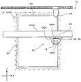
まず、図3に示すように、複層ガラスパネル100を水平にした状態でテーブル1202の載置面に載置して載置面と平行な面内での位置決めを行い載置面に移動不能に固定する。
複層ガラスパネル100の位置決めは、例えば、前記載置面に設けられた位置決め部材に複層ガラスパネル100の角部の直交する2辺を当て付けることで行う。また、複層ガラスパネル100の固定は、図示しない治具を用いて行う。 Next, the case where the glazing
First, as shown in FIG. 3, the
The positioning of the
治具板18の取着は作業員が手作業で行っても良く、作業ロボットにより自動的に行うようにしてもよい。
この際、塗布ノズル26は、第1板部18Aの上方に位置している。 Next, as shown in FIG. 9, the
The
At this time, the
この状態で、図4、図10、図15に示すように、複層ガラスパネル100と塗布ノズル26とを相対的に移動させつつ第1板部18Aの上に塗布ノズル26からグレージングガスケット成形材料110aを接着剤200Aと共に吐出して塗布する。
この際、複層ガラスパネル100と塗布ノズル26とをグレージングガスケット成形材料110aが対向する2辺1802、1804のうちの一方の辺1802から他方の辺1804に向かうように相対的に移動させる。
本実施の形態では、この相対的な移動は、塗布ノズル26を静止させておき、複層ガラスパネル移動機構12により複層ガラスパネル100をY軸方向に移動させることによってなされる。
これにより、治具板18上にグレージングガスケット成形材料110aの塗布始点g1を含む第1の塗布部分Z1がY軸方向に沿って延在形成される。 Next, the
In this state, as shown in FIGS. 4, 10, and 15, the glazing gasket molding material is applied from the
At this time, the
In the present embodiment, the relative movement is performed by keeping the
Thereby, the 1st application part Z1 including the application | coating start point g1 of the glazing
この場合にも、グレージングガスケット成形材料110aの複層ガラスパネル100の上面への塗布は、ダイス42の下端が複層ガラスパネル100の上面に押し当てられ、弾性部材50を圧縮しつつ行なわれる。
なお、グレージングガスケット成形材料110aの塗布時に、ダイス42の下端が複層ガラスパネル100の上面に押し当てられ、弾性部材50を常時圧縮するように構成されているので、弾性部材50の圧縮量の変化で第1板部18Aの厚さ分の段差を吸収でき、ダイス42の下端を複層ガラスパネル100の上面に押し当てるために、塗布ノズル昇降機構38を作動させる必要はない。すなわち、ダイス42が第1板部18Aを上り下りする毎に塗布ノズル昇降機構38を作動させる必要がない。この場合、第1板部18Aの上にダイス42が位置する場合と、複層ガラスパネル100の上にダイス42が位置する場合とでは、弾性部材50の圧縮量は厳密には異なり、第1板部18Aの上にダイス42が位置する場合の方が弾性部材50の圧縮量は0.2mm大きくなる。 Next, the
Also in this case, the glazing
In addition, since the lower end of the die 42 is pressed against the upper surface of the
次いで、複層ガラスパネル100と塗布ノズル26とを相対的に移動させ、詳細には、複層ガラスパネル100を静止させておき、塗布ノズル直線移動機構16により塗布ノズル26をX軸方向に沿って移動させる。
塗布ノズル26が複層ガラスパネル100の左上の角部に到達したならば、塗布ノズル旋回機構36により、塗布ノズル36を反時計方向に90度旋回させ、塗布ノズル直線移動機構16を停止させる。
次いで、複層ガラスパネル100と塗布ノズル26とを相対的に移動させ、詳細には、塗布ノズル26を静止させておき、複層ガラスパネル移動機構12により複層ガラスパネル100をY軸方向に沿って移動させる。
塗布ノズル26が複層ガラスパネル100の左下の角部に到達したならば、塗布ノズル旋回機構36により、塗布ノズル36を反時計方向に90度旋回させ、複層ガラスパネル移動機構12を停止させる。
次いで、図5に示すように、複層ガラスパネル100と塗布ノズル26とを相対的に移動させ、詳細には、複層ガラスパネル100を静止させておき、塗布ノズル直線移動機構16により塗布ノズル26をX軸方向に沿って移動させる。 When the
Next, the
When the
Next, the
When the
Next, as shown in FIG. 5, the
次いで、複層ガラスパネル100と塗布ノズル26とを相対的に移動させ、詳細には、塗布ノズル26を静止させておき、複層ガラスパネル移動機構12により複層ガラスパネル100をY軸方向に沿って移動させる。 When the
Next, the
この場合にも、塗布ノズル昇降機構38を作動させず、弾性部材50の圧縮量の変化で第1板部18Aの厚さ分の段差を吸収する。
これにより、一定の断面形状で塗布されたグレージングガスケット成形材料110aを治具板18の一方の辺1802から他方の辺1804に向かって治具板18上に延在させ、グレージングガスケット成形材料110aおよび接着剤200Aの吐出を停止させる。これにより第1板部18A上にグレージングガスケット成形材料110aの塗布終点g2を含む第2の塗布部分Z2を形成させる。 Soon, as shown in FIGS. 6 and 11, the
Also in this case, the step corresponding to the thickness of the
As a result, the glazing
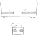
そして、図7に示すように、第1の塗布部分Z1がレーザー切断装置24によるレーザー光の照射位置に到達したならば、レーザー切断装置24を動作させる。
すなわち、第1板部18A上に塗布された第1の塗布部分Z1を第1板部18A上においてレーザー光を照射することにより切断する。これにより、図8(A)、図12、図17に示すように、複層ガラスパネル100の上面に塗布されたグレージングガスケット成形材料110aに第1の切断面S1が形成される。
第1の塗布部分Z1が切り離されたならば、複層ガラスパネル移動機構12により複層ガラスパネル100をさらにY軸方向に沿って移動させる。
そして、第2の塗布部分Z2がレーザー切断装置24によるレーザー光の照射位置に到達したならば、レーザー切断装置24を動作させる。
すなわち、第1板部18A上に塗布された第2の塗布部分Z2を第1板部18A上においてレーザー光を照射することにより切断する。これにより、図12、図17に示すように、複層ガラスパネル100の上面に塗布されたグレージングガスケット成形材料110aに第2の切断面S2が形成される。 Next, after the
Then, as shown in FIG. 7, when the first application portion Z1 reaches the irradiation position of the laser beam by the
That is, the 1st application part Z1 apply | coated on the
If the 1st application | coating part Z1 was cut away, the multilayer glass panel moving mechanism 12 will further move the
And if the 2nd application part Z2 reaches | attains the irradiation position of the laser beam by the
That is, the 2nd application part Z2 apply | coated on the
より詳細に説明すると、塗布始点g1を含む第1の塗布部分Z1および塗布終点g2を含む第2の塗布部分Z2が載せられた治具板18をそれら塗布部分と共に複層ガラスパネル100から取り除く。
この治具板18の取り除きは作業員が手作業で行っても良く、作業ロボットにより自動的に行うようにしてもよい。 When the first application part Z1 and the second application part Z2 are separated in this way, the
More specifically, the
The removal of the
より詳細には、複層ガラスパネル100の上面に塗布されたグレージングガスケット成形材料110aおよび接着剤に連続し第1板部18A上に残った、第1の切断面S1を有する第1の塗布部分Z1および第2の切断面S2を有する第2の塗布部分Z2を複層ガラスパネル100の上面に戻す。 Further, when the
In more detail, the 1st application part which has the 1st cut surface S1 which continued to the glazing
これにより、図1(A)に示すように、複層ガラスパネル100の上面の周縁部の全周にわたってグレージングガスケット110が成形される。 Then, as shown in FIGS. 1B and 8B, the glazing gasket molding material applied between the first cut surface S1 and the second cut surface S2 on the upper surface of the
Thereby, as shown to FIG. 1 (A), the
したがって、吐出口44から吐出されるグレージングガスケット成形材料110aの圧力をガラス面に掛けつつ塗布していくことができるので、塗布ノズル26を高速で移動させた場合であっても、グレージングガスケット成形材料110aをガラス面に確実に取着する上で、また、グレージングガスケット成形材料110aを所望の形状で成形する上で有利となる。
また、テーブル1202上に単に弾性部材50を配置する構成であるため、ダイス42側やテーブル1202側に機械的や電気的な付勢機構を設ける場合に比べ、構造が簡単であり、グレージングガスケット成形装置10のコストダウンを図る上で有利となる。
また、治具板18を用いて塗布始点g1および塗布終点g2を含む箇所を取り除く場合であっても、治具板18の箇所で塗布ノズル昇降機構38を作動させず、弾性部材50の圧縮量の変化で第1板部18Aの厚さ分の段差を吸収できる。
したがって、塗布始点および塗布終点の近傍箇所で、ダイス42あるいはテーブル1202を昇降させる制御は不要となり、グレージングガスケット成形装置10のコストダウンを図る上で有利となる。 According to the present embodiment, the glazing
Accordingly, since the pressure of the glazing
In addition, since the
Further, even when the place including the application start point g1 and the application end point g2 is removed using the
Therefore, it is not necessary to control the die 42 or the table 1202 to move up and down in the vicinity of the application start point and the application end point, which is advantageous in reducing the cost of the glazing
なお、治具板18に代え1枚の板体と、この板体を複層ガラスパネル100の上面に移動不能かつ脱着可能に取り付ける従来公知の様々な取付金具を用いてもよい。しかしながら、実施の形態の治具板18を用いると取付金具が不要となり、治具板18の脱着作業を簡単に行う上で有利となる。 Further, since the
Instead of the
Claims (6)
- テーブルに載置されたガラスパネルの上方に向けられた上面の外周部に、塗布ノズルの吐出口からグレージングガスケット成形材料を接着剤と共に吐出し前記ガラスパネルと前記塗布ノズルとを相対的に移動させて前記グレージングガスケット成形材料を塗布するに際して、
前記テーブルに弾性変形可能な材料からなる弾性部材を載置し、
前記ガラスパネルを前記弾性部材の上に載置し、
グレージングガスケット成形材料のガラスパネルの上面への塗布を、前記吐出口が形成された塗布ノズルの部分をガラスパネルの上面に押し当て前記弾性部材を圧縮しつつ、前記塗布ノズルの移動方向の後方に前記吐出口から斜め下方に向けて前記グレージングガスケットを前記接着剤と共に吐出することで行なう、
ことを特徴とするグレージングガスケット付きガラスパネルの製造方法。 The glazing gasket molding material is discharged together with the adhesive from the discharge port of the coating nozzle onto the outer peripheral portion of the upper surface of the glass panel placed on the table, and the glass panel and the coating nozzle are moved relative to each other. When applying the glazing gasket molding material,
Place an elastic member made of an elastically deformable material on the table,
Placing the glass panel on the elastic member;
Applying the glazing gasket molding material to the upper surface of the glass panel, pressing the portion of the application nozzle formed with the discharge port against the upper surface of the glass panel and compressing the elastic member, while moving backward in the moving direction of the application nozzle It is performed by discharging the glazing gasket together with the adhesive from the discharge port obliquely downward.
The manufacturing method of the glass panel with a glazing gasket characterized by the above-mentioned. - 前記ガラスパネルの上面の外周部の一部に治具板を移動不能かつ着脱可能に取着しておき、
前記治具板上において、グレージングガスケット成形材料の塗布始めの塗布始点と、塗布終了の塗布終点とを位置させて前記ガラスパネルの上面の外周部にグレージングガスケット成形材料を接着剤と共に塗布し、
前記治具板上において塗布始点と塗布終点とを含む箇所をレーザーにより切断し、それら塗布始点と塗布終点を含む箇所を前記治具板と共にガラスパネルの面上から取り除き、
前記塗布始点と塗布終点を含む箇所を取り除いたガラスパネルの上面箇所に、前記塗布されたグレージングガスケット成形材料と同一の断面形状のグレージングガスケット成形体を接着剤により接着するようにした、
ことを特徴とする請求項1記載のグレージングガスケット付きガラスパネルの製造方法。 A jig plate is attached to a part of the outer peripheral portion of the upper surface of the glass panel so as not to be movable and detachable,
On the jig plate, glazing gasket molding material is applied together with an adhesive on the outer periphery of the upper surface of the glass panel by positioning the application start point of the application of the glazing gasket molding material and the application end point of the application end,
Cutting the location including the application start point and the application end point on the jig plate with a laser, removing the location including the application start point and the application end point from the surface of the glass panel together with the jig plate,
The glazing gasket molded body having the same cross-sectional shape as that of the applied glazing gasket molding material was adhered to the upper surface portion of the glass panel from which the location including the coating start point and the coating end point was removed by an adhesive.
The manufacturing method of the glass panel with a glazing gasket of Claim 1 characterized by the above-mentioned. - テーブルに載置されたガラスパネルの上方に向けられた上面に、塗布ノズルの吐出口からグレージングガスケット成形材料を接着剤と共に吐出し前記ガラスパネルと前記塗布ノズルとを相対的に移動させて前記ガラスパネルの上面の外周部に前記グレージングガスケット成形材料を前記接着剤と共に塗布して取着するグレージングガスケット成形装置であって、
前記ガラスパネル載置用のテーブルと、
前記テーブルに載置された弾性変形可能な材料からなる弾性部材と、
グレージングガスケット成形材料を接着剤と共に吐出口から斜め下方に吐出する塗布ノズルと、
前記弾性部材の上に載置され位置決め固定されたガラスパネルの上面に、前記吐出口が形成された塗布ノズルの部分を押し当てる当接手段と、
前記塗布ノズルの移動方向の後方に前記吐出口から前記グレージングガスケット成形材料が前記ガラスパネルの上面の外周部に沿って吐出されるように前記ガラスパネルと前記塗布ノズルとを相対的に移動させる移動手段と、
を備えることを特徴とするグレージングガスケット成形装置。 On the upper surface of the glass panel placed on the table, the glazing gasket molding material is discharged together with an adhesive from the discharge port of the coating nozzle, and the glass panel and the coating nozzle are moved relative to each other to form the glass. A glazing gasket molding apparatus that applies and attaches the glazing gasket molding material together with the adhesive to an outer peripheral portion of an upper surface of a panel,
A table for placing the glass panel;
An elastic member made of an elastically deformable material placed on the table;
An application nozzle that discharges the glazing gasket molding material obliquely downward from the discharge port together with the adhesive;
A contact means for pressing a portion of the application nozzle formed with the discharge port on the upper surface of the glass panel placed and fixed on the elastic member;
Movement for relatively moving the glass panel and the coating nozzle so that the glazing gasket molding material is discharged from the discharge port along the outer peripheral portion of the upper surface of the glass panel behind the movement direction of the coating nozzle. Means,
A glazing gasket forming apparatus comprising: - 前記ガラスパネルの外周部の一部に移動不能かつ着脱可能に取着される治具板と、
前記グレージングガスケット成形材料を切断するレーザー切断装置とをさらに備え、
前記治具板は、互いに対向する2つの板部と、それら板部の端部間を接続する接続板部とを有し、
前記2つの板部は前記レーザー切断装置から発せられるレーザーの透過を不能とする材料で形成され、
前記2つの板部の間に前記ガラスパネルの外周部を位置させると、それら2つの板部により前記ガラスパネルが挟持され、前記治具板が前記ガラスパネルに移動不能かつ着脱可能に取着され、
前記2つの板部のうちの一方の板部が前記ガラスパネルの上面の外周部の一部に配置される、
ことを特徴とする請求項3記載のグレージングガスケット成形装置。 A jig plate that is immovably and detachably attached to a part of the outer periphery of the glass panel;
A laser cutting device for cutting the glazing gasket molding material,
The jig plate has two plate portions facing each other, and a connection plate portion that connects between the end portions of the plate portions,
The two plate portions are formed of a material that cannot transmit a laser emitted from the laser cutting device,
When the outer peripheral portion of the glass panel is positioned between the two plate portions, the glass panel is sandwiched between the two plate portions, and the jig plate is attached to the glass panel so as not to be movable and detachable. ,
One plate portion of the two plate portions is disposed on a part of the outer peripheral portion of the upper surface of the glass panel.
The glazing gasket forming apparatus according to claim 3. - 前記治具板は、互いに対向する第1板部および第2板部と、それら板部の端部を接続する接続板部とを有して断面コ字状を呈し、
前記互いに対向する2つの板部は、前記第1板部と前記第2板部であり、
前記第1板部が前記接続板部から突出する長さは、前記第2板部が前記接続板部から突出する長さよりも大きな寸法で形成され、
前記ガラスパネルの上面の外周部の一部に配置される前記一方の板部は、前記第1板部である、
ことを特徴とする請求項4記載のグレージングガスケット成形装置。 The jig plate has a first plate portion and a second plate portion facing each other, and a connecting plate portion connecting the end portions of the plate portions, and has a U-shaped cross section.
The two plate portions facing each other are the first plate portion and the second plate portion,
The length by which the first plate portion protrudes from the connection plate portion is formed with a dimension larger than the length by which the second plate portion protrudes from the connection plate portion,
The one plate portion disposed on a part of the outer peripheral portion of the upper surface of the glass panel is the first plate portion.
The glazing gasket forming apparatus according to claim 4. - 前記ガラスパネルの上面に押し当てられる塗布ノズルの部分の進行方向の前方に、前方に至るにつれて前記ガラスパネルから次第に離れる傾斜面が形成されている、
ことを特徴とする請求項3乃至5に何れか1項記載のグレージングガスケット成形装置。 An inclined surface gradually formed away from the glass panel as it reaches the front is formed in the forward direction of the portion of the application nozzle pressed against the upper surface of the glass panel.
The glazing gasket forming apparatus according to any one of claims 3 to 5, wherein
Priority Applications (4)
| Application Number | Priority Date | Filing Date | Title |
|---|---|---|---|
| JP2012547378A JP5522268B2 (en) | 2011-06-14 | 2012-06-14 | Manufacturing method of glass panel with glazing gasket and glazing gasket forming apparatus |
| DE112012002462.1T DE112012002462B4 (en) | 2011-06-14 | 2012-06-14 | Method and device for producing a glass plate with a glazing gasket |
| CN201280029263.4A CN103596899B (en) | 2011-06-14 | 2012-06-14 | Method for producing glass panel having glazing gasket attached thereto, and glazing gasket molding device |
| US14/126,422 US9187368B2 (en) | 2011-06-14 | 2012-06-14 | Manufacturing method for glass panel with glazing gasket and glazing gasket molding apparatus |
Applications Claiming Priority (2)
| Application Number | Priority Date | Filing Date | Title |
|---|---|---|---|
| JP2011-131823 | 2011-06-14 | ||
| JP2011131823 | 2011-06-14 |
Publications (1)
| Publication Number | Publication Date |
|---|---|
| WO2012172801A1 true WO2012172801A1 (en) | 2012-12-20 |
Family
ID=47356807
Family Applications (1)
| Application Number | Title | Priority Date | Filing Date |
|---|---|---|---|
| PCT/JP2012/003884 WO2012172801A1 (en) | 2011-06-14 | 2012-06-14 | Method for producing glass panel having glazing gasket attached thereto, and glazing gasket molding device |
Country Status (5)
| Country | Link |
|---|---|
| US (1) | US9187368B2 (en) |
| JP (1) | JP5522268B2 (en) |
| CN (1) | CN103596899B (en) |
| DE (1) | DE112012002462B4 (en) |
| WO (1) | WO2012172801A1 (en) |
Cited By (1)
| Publication number | Priority date | Publication date | Assignee | Title |
|---|---|---|---|---|
| JP5510558B2 (en) * | 2011-06-17 | 2014-06-04 | 横浜ゴム株式会社 | Manufacturing method and manufacturing apparatus for glass panel with glazing gasket |
Citations (3)
| Publication number | Priority date | Publication date | Assignee | Title |
|---|---|---|---|---|
| JPH0768620A (en) * | 1993-07-02 | 1995-03-14 | Asahi Glass Co Ltd | Production of window body with synthetic resin frame |
| JP2009068191A (en) * | 2007-09-11 | 2009-04-02 | Yokohama Rubber Co Ltd:The | Method of manufacturing glass with glazing gasket |
| WO2011024483A1 (en) * | 2009-08-31 | 2011-03-03 | 横浜ゴム株式会社 | Method for manufacturing double-glazed glass panel and device for molding glazing gasket |
Family Cites Families (8)
| Publication number | Priority date | Publication date | Assignee | Title |
|---|---|---|---|---|
| EP0568014B1 (en) * | 1992-04-28 | 1998-10-21 | Asahi Glass Company Ltd. | Method of making a window panel with a synthetic resin frame |
| DE4232554C1 (en) * | 1992-09-29 | 1994-01-05 | Ver Glaswerke Gmbh | Method for producing a glass pane provided with a molded frame made of a thermoplastic polymer and device for carrying out the method |
| US5489409A (en) * | 1993-06-25 | 1996-02-06 | Asahi Glass Company, Ltd. | Method of making a window frame and a window panel with a window frame |
| DE4326650A1 (en) * | 1993-08-09 | 1995-02-16 | Ver Glaswerke Gmbh | Method and devices for producing a glass pane provided with a molded-on frame made of a polymer |
| US5846465A (en) * | 1995-03-16 | 1998-12-08 | Asahi Glass Company, Ltd. | Method for preparing a plate member for a window with a resinous frame |
| DE10103865C1 (en) * | 2001-01-30 | 2002-05-02 | Saint Gobain Sekurit D Gmbh | Formation of edging profile on a pane of two sheets of glass held together by an adhesive, comprises forming the edging on a pane whose shape is determined by the shape of a molding bed, no adhesion promoter being present on edge of pane |
| US7819999B2 (en) * | 2004-10-27 | 2010-10-26 | The Yokohama Rubber Co., Ltd. | Method and device for manufacturing double-glazing panel with glazing gasket |
| CN102802911B (en) * | 2009-06-09 | 2015-03-04 | 横滨橡胶株式会社 | Method of and apparatus for molding glazing gasket onto multilayer glass panel |
-
2012
- 2012-06-14 JP JP2012547378A patent/JP5522268B2/en not_active Expired - Fee Related
- 2012-06-14 CN CN201280029263.4A patent/CN103596899B/en not_active Expired - Fee Related
- 2012-06-14 DE DE112012002462.1T patent/DE112012002462B4/en not_active Expired - Fee Related
- 2012-06-14 US US14/126,422 patent/US9187368B2/en not_active Expired - Fee Related
- 2012-06-14 WO PCT/JP2012/003884 patent/WO2012172801A1/en active Application Filing
Patent Citations (3)
| Publication number | Priority date | Publication date | Assignee | Title |
|---|---|---|---|---|
| JPH0768620A (en) * | 1993-07-02 | 1995-03-14 | Asahi Glass Co Ltd | Production of window body with synthetic resin frame |
| JP2009068191A (en) * | 2007-09-11 | 2009-04-02 | Yokohama Rubber Co Ltd:The | Method of manufacturing glass with glazing gasket |
| WO2011024483A1 (en) * | 2009-08-31 | 2011-03-03 | 横浜ゴム株式会社 | Method for manufacturing double-glazed glass panel and device for molding glazing gasket |
Cited By (1)
| Publication number | Priority date | Publication date | Assignee | Title |
|---|---|---|---|---|
| JP5510558B2 (en) * | 2011-06-17 | 2014-06-04 | 横浜ゴム株式会社 | Manufacturing method and manufacturing apparatus for glass panel with glazing gasket |
Also Published As
| Publication number | Publication date |
|---|---|
| CN103596899B (en) | 2015-03-11 |
| DE112012002462B4 (en) | 2016-01-07 |
| DE112012002462T5 (en) | 2014-02-27 |
| US20140110044A1 (en) | 2014-04-24 |
| JPWO2012172801A1 (en) | 2015-02-23 |
| CN103596899A (en) | 2014-02-19 |
| JP5522268B2 (en) | 2014-06-18 |
| US9187368B2 (en) | 2015-11-17 |
Similar Documents
| Publication | Publication Date | Title |
|---|---|---|
| KR101746650B1 (en) | a apparatus of curved display manufacturing, and a method of curved display manufacturing | |
| TW201111131A (en) | Method and apparatus for cutting sheet material | |
| TW200625393A (en) | Driving mechanism for chip detachment apparatus | |
| KR20180033851A (en) | Clean apparatus for press | |
| JP5522268B2 (en) | Manufacturing method of glass panel with glazing gasket and glazing gasket forming apparatus | |
| JP4662086B2 (en) | Multilayer glass panel manufacturing method and glazing gasket forming apparatus | |
| CN112606411A (en) | PVC plate laminating device with automatic gluing structure | |
| JP2008194777A (en) | End face cutting device and end face cutting method | |
| CN111315560B (en) | Laminating equipment | |
| JP5440035B2 (en) | Plate member support device | |
| KR101796057B1 (en) | Substrate cutting apparatus | |
| CN111761914B (en) | Automatic plywood pasting system and pasting method | |
| CN113666622A (en) | Cutting device is used in TFT module production that possesses clearance function | |
| JP4412414B2 (en) | Method and apparatus for forming glazing gasket for multi-layer glass panel | |
| KR101560473B1 (en) | Manufacturing apparatus and method for a cliche of Metal-Mesh | |
| CN218778342U (en) | Laminated board reworking device | |
| JP5505515B2 (en) | Method and apparatus for mounting molding material and coating nozzle | |
| TWM461528U (en) | Scrap peeling device for film cutting machine | |
| CN115890755B (en) | Cover plate fabric coating pressure maintaining mold and application method thereof | |
| CN216581253U (en) | Plane sticking film machine | |
| CN219987883U (en) | Cutting equipment is used in desk panel processing | |
| JP2004009698A (en) | Apparatus, die and method for trimming molding | |
| CN210551571U (en) | Automobile sound-proof cotton easy-to-lift stripping and pressing line die with glue | |
| CN112388963A (en) | Adsorb compression fittings | |
| JPH049656B2 (en) |
Legal Events
| Date | Code | Title | Description |
|---|---|---|---|
| ENP | Entry into the national phase |
Ref document number: 2012547378 Country of ref document: JP Kind code of ref document: A |
|
| 121 | Ep: the epo has been informed by wipo that ep was designated in this application |
Ref document number: 12799967 Country of ref document: EP Kind code of ref document: A1 |
|
| WWE | Wipo information: entry into national phase |
Ref document number: 14126422 Country of ref document: US |
|
| WWE | Wipo information: entry into national phase |
Ref document number: 112012002462 Country of ref document: DE Ref document number: 1120120024621 Country of ref document: DE |
|
| 122 | Ep: pct application non-entry in european phase |
Ref document number: 12799967 Country of ref document: EP Kind code of ref document: A1 |