WO2012165189A1 - 圧電モータおよび圧電モータ装置 - Google Patents
圧電モータおよび圧電モータ装置 Download PDFInfo
- Publication number
- WO2012165189A1 WO2012165189A1 PCT/JP2012/062905 JP2012062905W WO2012165189A1 WO 2012165189 A1 WO2012165189 A1 WO 2012165189A1 JP 2012062905 W JP2012062905 W JP 2012062905W WO 2012165189 A1 WO2012165189 A1 WO 2012165189A1
- Authority
- WO
- WIPO (PCT)
- Prior art keywords
- individual electrode
- mode
- electrode
- common electrode
- piezoelectric
- Prior art date
- Legal status (The legal status is an assumption and is not a legal conclusion. Google has not performed a legal analysis and makes no representation as to the accuracy of the status listed.)
- Ceased
Links
Images



Classifications
-
- H—ELECTRICITY
- H02—GENERATION; CONVERSION OR DISTRIBUTION OF ELECTRIC POWER
- H02N—ELECTRIC MACHINES NOT OTHERWISE PROVIDED FOR
- H02N2/00—Electric machines in general using piezoelectric effect, electrostriction or magnetostriction
- H02N2/0005—Electric machines in general using piezoelectric effect, electrostriction or magnetostriction producing non-specific motion; Details common to machines covered by H02N2/02 - H02N2/16
- H02N2/001—Driving devices, e.g. vibrators
-
- H—ELECTRICITY
- H02—GENERATION; CONVERSION OR DISTRIBUTION OF ELECTRIC POWER
- H02N—ELECTRIC MACHINES NOT OTHERWISE PROVIDED FOR
- H02N2/00—Electric machines in general using piezoelectric effect, electrostriction or magnetostriction
- H02N2/02—Electric machines in general using piezoelectric effect, electrostriction or magnetostriction producing linear motion, e.g. actuators; Linear positioners ; Linear motors
- H02N2/026—Electric machines in general using piezoelectric effect, electrostriction or magnetostriction producing linear motion, e.g. actuators; Linear positioners ; Linear motors by pressing one or more vibrators against the driven body
-
- H—ELECTRICITY
- H10—SEMICONDUCTOR DEVICES; ELECTRIC SOLID-STATE DEVICES NOT OTHERWISE PROVIDED FOR
- H10N—ELECTRIC SOLID-STATE DEVICES NOT OTHERWISE PROVIDED FOR
- H10N30/00—Piezoelectric or electrostrictive devices
- H10N30/20—Piezoelectric or electrostrictive devices with electrical input and mechanical output, e.g. functioning as actuators or vibrators
Definitions
- the present invention relates to a piezoelectric motor that displaces a power transmission unit by utilizing deformation of a piezoelectric plate, and a piezoelectric motor device that converts the displacement of the power transmission unit into power of rotational motion or linear motion.
- Piezoelectric motors are motors powered by the displacement of the power transmission section accompanying the deformation of the piezoelectric plate.
- the piezoelectric motor device converts the power of the piezoelectric motor into rotational motion or linear motion and uses it as power.
- FIG. 1 is a diagram illustrating a basic configuration of a piezoelectric motor device 101 with reference to Patent Document 1.
- FIG. 1A is a perspective view of the piezoelectric motor device 101.
- FIG. 1B is a circuit diagram of the piezoelectric motor device 101.
- FIG. 1C is a partially enlarged plan view of the piezoelectric motor device 101.
- a coordinate system is added.
- the piezoelectric motor device 101 includes a piezoelectric plate 102, individual electrodes 103A and 103B, a common electrode 104, an AC source 105A, a switch 105B, a pressing spring 106, a frame 107, a bearing 108, and a linear slider 109.
- the piezoelectric plate 102, the individual electrodes 103A and 103B, the common electrode 104, the AC source 105A, and the switch 105B constitute a piezoelectric motor.
- the piezoelectric plate 102 is a flat plate having a rectangular main surface facing the Z-axis, and a protrusion 102A is provided on the side surface in the positive Y-axis direction.
- the individual electrodes 103A and 103B are provided on the front main surface of the piezoelectric plate 102 in line symmetry with respect to a straight line along the Y-axis direction passing through the position where the protrusion 102A is provided.
- the common electrode 104 is provided on substantially the entire back main surface of the piezoelectric plate 102.
- the AC source 105A is connected between the common electrode 104 and the switch 105B, and the individual electrodes 103A and 103B are selectively connected to the AC source 105A by the switch 105B.
- a linear slider 109 is disposed in the Y axis positive direction of the piezoelectric plate 102, and a bearing 108 is disposed in the Y axis positive direction of the linear slider 109.
- a pressing spring 106 is disposed in the negative Y-axis direction of the piezoelectric plate 102. The pressing spring 106 is supported by the frame 107 and presses the piezoelectric plate 102 toward the linear slider 109.
- the piezoelectric plate 102 When the individual electrode 103A is connected to the AC source 105A by the switch 105B and an AC voltage is applied between the individual electrode 103A and the common electrode 104 by the AC source 105A, the piezoelectric plate 102 is deformed in the XY plane, and the protrusion The part 102A is displaced by a linear reciprocating orbit having a predetermined inclination with respect to the X axis and the Y axis.
- the projecting portion 102A displaced as described above collides with the side surface of the linear slider 109 in the negative Y-axis direction, whereby the power in the negative X-axis direction is transmitted from the projecting portion 102A to the linear slider 109, and the linear slider 109 is transmitted to the X-axis. It can be moved in the negative direction.
- the switch 105B and connecting the individual electrode 103B to the AC source 105A the moving direction of the linear slider 109 can be switched to the reverse direction.
- an object of the present invention is to provide a piezoelectric motor and a piezoelectric motor device having a simple configuration in which dynamic friction hardly occurs and power transmission efficiency is high.
- the piezoelectric motor according to the present invention includes a piezoelectric plate, a power transmission unit, and a drive unit.
- the piezoelectric plate has a first surface including a first region and a second region adjacent to each other.
- the power transmission unit is provided on a boundary line between the first region and the second region, and is displaced in a first direction along the boundary line, and is also in a direction normal to the first surface of the piezoelectric plate and the first direction. It is displaced in a second direction perpendicular to the direction of.
- the drive unit is provided on the first individual electrode provided in the first region, the second individual electrode provided in the second region, and the second surface facing the first surface of the piezoelectric plate. An AC voltage is applied between the first individual electrode and the common electrode, and the second individual electrode is prevented from becoming a floating electrode.
- the power transmission unit provided on the boundary line between the first region and the second region is displaced by a circular or elliptical orbit, not a linear reciprocating orbit.
- the drive unit has one side connected to the first individual electrode, the other side connected to the second individual electrode and the common electrode, and the first individual electrode and the common electrode.
- the second individual electrode, the common electrode, and the other side of the AC source are preferably connected to the ground.
- the drive unit applies an AC voltage corresponding to a resonance frequency whose vibration mode is the E (3,1) mode between the first individual electrode and the common electrode.
- the drive unit simultaneously excites the symmetric mode vibration of the E (3,1) mode and the vibration of the asymmetric mode on the entire piezoelectric plate, and the phase difference between the symmetric mode of the E (3,1) mode and the asymmetric mode. It is preferable to apply an AC voltage between the first individual electrode and the common electrode so that is 90 °.
- the driving unit includes an AC source that applies an AC voltage between the first individual electrode or the second individual electrode and the common electrode, and one side of the AC source is the first source. Connected to the individual electrode, the other side is connected to the second individual electrode and the common electrode, and the second individual electrode, the common electrode and the other side of the AC source are connected to the ground; One side of the AC source is connected to the second individual electrode, the other side is connected to the first individual electrode and the common electrode, and the first individual electrode, the common electrode, and the other side of the AC source are grounded. It is preferable to provide a switch for switching between the state connected to the.
- the drive unit applies an AC voltage corresponding to a resonance frequency whose vibration mode is the E (3,1) mode between the first individual electrode or the second individual electrode and the common electrode. . Further, the drive unit simultaneously excites the symmetric mode vibration of the E (3,1) mode and the vibration of the asymmetric mode on the entire piezoelectric plate, and the phase difference between the symmetric mode of the E (3,1) mode and the asymmetric mode. It is preferable to apply an AC voltage between the first individual electrode or the second individual electrode and the common electrode so that the angle is about 90 °.
- the drive unit has one side connected to the first individual electrode, the other side connected to the common electrode, and an alternating current between the first individual electrode and the common electrode.
- a first AC source for applying a voltage one side is connected to a second individual electrode, the other side is connected to a common electrode, and an AC voltage is applied between the second individual electrode and the common electrode
- the other side of the first AC source and the other side of the second AC source are connected to the ground.
- the drive unit corresponds to a resonance frequency in which the vibration mode is the E (3,1) mode between the first individual electrode and the common electrode and between the second individual electrode and the common electrode. It is preferable to apply an alternating voltage.
- the drive unit simultaneously excites the symmetric mode vibration of the E (3,1) mode and the vibration of the asymmetric mode on the entire piezoelectric plate, and the phase difference between the symmetric mode of the E (3,1) mode and the asymmetric mode. It is preferable to apply an AC voltage between the first individual electrode and the common electrode and between the second individual electrode and the common electrode so that the angle is about 90 °.
- the piezoelectric motor device preferably includes any one of the above-described piezoelectric motors and a power conversion unit disposed on the first direction side of the piezoelectric plate.
- the power conversion unit may be a linear slider that is movable with the second direction as the movement direction.
- a power conversion unit such as a linear slider can be driven by a piezoelectric motor, and the feed motion of the piezoelectric motor can be converted into a linear motion or the like to be used as power.
- the power transmission unit is displaced so as to draw a circular or elliptical orbit instead of a linear reciprocating orbit
- the second The displacement in the direction (X axis) is small, and after the displacement in the first direction (Y axis) is small, the displacement in the second direction (X axis) is large. Therefore, when this power transmission part collides with the power conversion part which opposes a 2nd direction (Y-axis), it becomes difficult to produce dynamic friction, and wear and energy loss with a power transmission part and a power conversion part can be suppressed.
- FIG. 6 is a circuit diagram of a piezoelectric motor device according to a third embodiment of the present invention.
- FIG. 2 is a diagram illustrating the configuration of the piezoelectric motor device 1 according to the first embodiment of the present invention.
- FIG. 2A is a perspective view of the piezoelectric motor device 1.
- FIG. 2B is a circuit diagram of the piezoelectric motor device 1.
- FIG. 2C is a partially enlarged plan view of the piezoelectric motor device 1.
- the orthogonal direction with the normal direction of the main surface of the piezoelectric plate 2 included in the piezoelectric motor device 1 as the Z-axis direction, the longitudinal direction of the main surface as the X-axis direction, and the short direction of the main surface as the Y-axis direction A coordinate system is added.
- the piezoelectric motor device 1 includes a piezoelectric plate 2, individual electrodes 3A and 3B, a common electrode 4, an AC source 5, a pressing spring 6, a frame 7, a bearing 8, and a linear slider 9.
- the piezoelectric plate 2, the individual electrodes 3A and 3B, the common electrode 4, and the AC source 5 constitute the piezoelectric motor in this embodiment, and the individual electrodes 3A and 3B, the common electrode 4, and the AC source 5 are driving units in this embodiment.
- the linear slider 9 is a power conversion unit in the present embodiment.
- Piezoelectric plate 2 is a flat plate having a main surface facing the Z-axis having a rectangular shape, and the main surface facing the Z-axis includes a first region and a second region adjacent to each other.
- a protrusion 2A is provided on the side surface in the positive direction of the Y axis on the boundary line between the first region and the second region of the piezoelectric plate 2.
- the protrusion 2A is a power transmission unit in the present embodiment.
- the individual electrodes 3A and 3B are provided on the main surface of the piezoelectric plate 2 facing the Z axis.
- the individual electrodes 3A and 3B are provided symmetrically with respect to a straight line along the Y-axis direction that passes through the position where the protrusion 2A is provided.
- the individual electrode 3A is provided in the first region
- the individual electrode 3B is provided in the second region.
- the common electrode 4 is provided on substantially the entire main surface facing the main surface facing the Z axis of the piezoelectric plate 2.
- the AC source 5 has one side connected to the individual electrode 3 ⁇ / b> A and the other side connected to the individual electrode 3 ⁇ / b> B and the common electrode 4.
- a connection point of the AC source 5, the individual electrode 3B, and the common electrode 4 is connected to the ground. That is, the individual electrode 3B, the common electrode 4, and the other side of the AC source 5 are connected to the ground.
- the frame 7 has ribs that rise in the positive direction of the Z-axis from the XY plane at both ends of the Y-axis.
- a linear slider 9 is disposed in the positive direction of the Y axis of the piezoelectric plate 2.
- the linear slider 9 has a rectangular bar-like configuration with the X-axis direction as the longitudinal direction.
- a bearing 8 is disposed in the positive direction of the Y-axis of the linear slider 9. The bearing 8 is in rolling contact with a linear slider 9 that moves in the X-axis direction.
- a pressing spring 6 is disposed in the negative Y-axis direction of the piezoelectric plate 2. The pressing spring 6 is supported by the rib of the frame 7 and presses the piezoelectric plate 2 toward the linear slider 9.
- an AC voltage corresponding to a resonance frequency whose vibration mode is the E (3, 1) mode is applied between the individual electrode 3A and the common electrode 4, so that E (3 1) The vibration of the asymmetric mode of the mode is excited.
- E (3, 1) mode symmetric mode vibrations are excited.
- the symmetric mode of the E (3,1) mode has substantially the same resonance frequency as the asymmetric mode of the E (3,1) mode.
- an AC voltage corresponding to a resonance frequency whose vibration mode is the E (3,1) mode is applied between the individual electrode 3A and the common electrode 4, so that E (3,1) is applied to the entire piezoelectric plate 2.
- the symmetric mode vibration and the asymmetric mode vibration are excited simultaneously.
- a phase difference between the symmetric mode of the E (3,1) mode and the asymmetric mode results in a phase difference between the symmetric mode and the asymmetric mode of the E (3,1) mode.
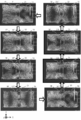
- FIG. 3 is a diagram for explaining the displacement vector of the piezoelectric plate 2 of the piezoelectric motor device 1 according to this embodiment.
- a sine wave signal is applied to the individual electrode 3A in the right hand region of the piezoelectric plate 2 on the right side in the drawing, and the individual electrode 3B in the left hand region of the piezoelectric plate 2 on the left side in the drawing is connected to the ground together with the common electrode 4.
- the example which analyzed the displacement vector by the finite element method about the structure which has been shown is shown.
- a displacement vector having a larger contraction direction is generated in the right-hand region of the piezoelectric plate 2 than in the case where the phase is 0 °, and the expansion direction is smaller in the left-hand region than when the phase is 0 °.
- the displacement vector is generated.
- a displacement vector in the direction of about 0 ° is generated counterclockwise with respect to the positive X-axis direction.
- the displacement vector in the maximum contraction direction is generated in the right-hand region of the piezoelectric plate 2 than in the case of 45 °, and in the left-hand region, the phase is 45 °.
- a small expansion direction displacement vector is generated.
- a displacement vector in the direction of about 315 ° is generated counterclockwise with respect to the positive X-axis direction.
- a displacement vector in the contraction direction is smaller in the right hand region of the piezoelectric plate 2 than in the case where the phase is 90 °, and a displacement vector in the contraction direction is generated in the left hand region.
- a displacement vector in a direction of about 270 ° is generated counterclockwise with respect to the positive X-axis direction.
- a displacement vector in the expansion direction is generated in the right-hand region of the piezoelectric plate 2, and a displacement vector in the contraction direction is generated in the left-hand region, compared to when the phase is 135 °.
- a displacement vector in the direction of about 225 ° is generated counterclockwise with respect to the positive X-axis direction.
- phase of the sine wave signal When the phase of the sine wave signal is 225 °, a displacement vector in the expansion direction that is larger in the right-hand region of the piezoelectric plate 2 than in the case of 180 ° is generated, and in the left-hand region, the phase is larger than that in the case of 180 °.
- the displacement vector in the maximum extension direction is generated in the right-hand region of the piezoelectric plate 2 than in the case of 225 °, and the displacement vector in the maximum expansion direction is generated, and in the left-hand region, the phase is 225 °.
- a small contraction direction displacement vector is generated.
- a displacement vector in the direction of about 135 ° is generated counterclockwise with respect to the positive X-axis direction.
- the piezoelectric plate 2 is deformed as described above, an AC voltage is applied between the individual electrode 3A and the common electrode 4 so that the phase difference between the symmetric mode and the asymmetric mode of the E (3,1) mode is about 90 °. Is applied, vibration of an elliptical motion in which a symmetric mode and an asymmetric mode of the E (3,1) mode are combined is generated, and a protrusion provided at the boundary between the left hand region and the right hand region of the piezoelectric plate 2 The displacement vector of the part 2A rotates clockwise. For this reason, the projection 2A is displaced so as to draw a clockwise circular or elliptical orbit.
- the protrusion 2A is displaced in the Y-axis direction and is displaced in the X-axis direction.
- the projection 2A collides with the side surface of the linear slider 9 in the Y-axis negative direction, so that power in the X-axis positive direction is transmitted from the projection 2A to the linear slider 9.
- the slider 9 moves in the positive direction of the X axis.
- the protrusion 2A is displaced in a circular or elliptical orbit as described above, when the protrusion 2A is largely displaced along the Y axis, the displacement along the X axis is small and the protrusion 2A is large along the Y axis. After the displacement, the displacement greatly occurs along the X axis. Therefore, in the configuration of the present embodiment, the dynamic friction between the protrusion 2A and the linear slider 9 hardly occurs, wear and energy loss of both can be suppressed, and the power transmission efficiency from the protrusion 2A to the linear slider 9 can be enhanced.
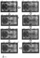
- FIG. 4 is a diagram for explaining a displacement vector of the piezoelectric plate 102 of the piezoelectric motor device 101 according to the conventional configuration.
- a finite element is applied to a configuration in which a sine wave signal is applied to the individual electrode 103A in the right hand region of the piezoelectric plate 102 on the right side in the drawing and the individual electrode 103B in the left hand region of the piezoelectric plate 102 on the left side in the drawing is in an open state.
- the example which analyzed the displacement vector by the method is shown.
- a displacement vector having a larger contraction direction is generated in the right-hand region of the piezoelectric plate 102 than in the case where the phase is 45 °, but almost no displacement vector is generated in the left-hand region. Then, in the vicinity of the protrusion 102A, a displacement vector having a direction of about 315 ° larger than the case where the phase is 45 ° is generated counterclockwise with respect to the positive direction of the X axis.
- the phase in the right hand region of the piezoelectric plate 102 is larger than that in the case of 90 °, and a displacement vector in the maximum contraction direction is generated, but almost no displacement vector is generated in the left hand region.
- a displacement vector having a maximum direction of about 315 ° is generated counterclockwise with respect to the positive direction of the X axis as compared with the case where the phase is 90 °.
- a displacement vector having a smaller contraction direction is generated in the right-hand region of the piezoelectric plate 102 than in the case where the phase is 135 °, but almost no displacement vector is generated in the left-hand region. Then, in the vicinity of the protrusion 102A, a displacement vector having a direction of about 315 ° smaller than that in the case where the phase is 135 ° is generated counterclockwise with respect to the positive direction of the X axis.
- a displacement vector in a larger expansion direction is generated in the right-hand region of the piezoelectric plate 102 than in the case where the phase is 225 °, but almost no displacement vector is generated in the left-hand region.
- a displacement vector in a direction of about 135 ° is generated counterclockwise with respect to the positive X-axis direction as compared with a phase of 225 °.
- the phase vector is larger in the right hand region of the piezoelectric plate 102 than in the case of 270 ° and the maximum displacement vector in the expansion direction is generated, but almost no displacement vector is generated in the left hand region.
- a displacement vector having a maximum direction of about 135 ° is generated counterclockwise with respect to the positive X-axis direction as compared with the case where the phase is 225 °.
- FIG. 5 is a circuit diagram of the piezoelectric motor device 11 according to the present embodiment.
- the piezoelectric motor device 11 includes a switch 15A for switching an individual electrode connected to one side of the AC source 5 and an individual electrode connected to the other side of the AC source 5.
- one side of the AC source 5 is connected to the individual electrode 3A, the other side is connected to the individual electrode 3B and the common electrode 4, and a connection point between the AC source 5, the individual electrode 3B, and the common electrode 4 Is connected to the ground, and one side of the AC source 5 is connected to the individual electrode 3B, the other side is connected to the individual electrode 3A and the common electrode 4, and is common to the AC source 5 and the individual electrode 3A.
- the switches 15A and 15B are controlled so as to switch between the state in which the connection point with the electrode 4 is connected to the ground.
- one side of the AC source 5 is connected to the individual electrode 3B, the other side is connected to the individual electrode 3A and the common electrode 4, and the connection point of the AC source 5, the individual electrode 3A and the common electrode 4 is the ground.
- the piezoelectric motor device 11 When the piezoelectric motor device 11 is connected to the piezoelectric motor device 11, the piezoelectric motor device 11 performs the reverse operation of the piezoelectric motor device 1 of the first embodiment, and the protrusion (not shown) is displaced in a counterclockwise circular or elliptical orbit.
- the linear slider (not shown) is moved in the negative direction of the X axis. Therefore, the piezoelectric motor device 11 of the present embodiment can switch the moving direction of the linear slider by the control of the switches 15A and 15B.
- FIG. 6 is a circuit diagram of the piezoelectric motor device 12 according to the present embodiment.
- the piezoelectric motor device 12 includes an AC source 5A in addition to the circuit configuration of the piezoelectric motor device 1 described above. That is, the piezoelectric motor device 12 has a two-phase power source. One side of the AC source 5 is connected to the individual electrode 3A, one side of the AC source 5A is connected to the individual electrode 3B, and the other side of the AC source 5 and the AC source 5A is connected to the common electrode 4. A connection point of the source 5, the AC source 5A, and the common electrode 4 is connected to the ground.
- a sin ( ⁇ t) sine wave signal is applied from the AC source 5 to the individual electrode 3A
- a cos ( ⁇ t) sine wave signal is applied from the AC source 5A to the individual electrode 3B.
- An AC voltage is applied between the individual electrodes 3A, 3B and the common electrode 4 so that the phase difference between the symmetric mode and the asymmetric mode of the mode is 90 °. Similar to the piezoelectric motor device 1, the vibration of the elliptical motion in which the symmetric mode and the asymmetric mode of the E (3,1) mode are combined is excited. Therefore, the piezoelectric motor device 12 performs the same operation as the piezoelectric motor device 1 of the first embodiment.
- a rotor that rotates in addition to the linear slider may be a power transmission target.
- the rotor can be rotated by a piezoelectric motor to obtain power of rotational motion.
Landscapes
- General Electrical Machinery Utilizing Piezoelectricity, Electrostriction Or Magnetostriction (AREA)
Abstract
動摩擦が起こりにくく動力伝達効率が高い簡易な構成の圧電モータおよび圧電モータ装置の提供を図る。圧電モータ装置(1)は、圧電板(2)と、突起部(2A)と、駆動部と、を備える。圧電板(2)は、互いに隣接する第1の領域と第2の領域とを含む第1の面を有する。突起部(2A)は、第1の領域と第2の領域との境界線上に設けられ、境界線に沿ったY軸方向に変位するとともに、圧電板(2)の第1の面の法線方向とY軸方向とに対して垂直なX軸方向に変位する。駆動部は、第1の領域に設けられた個別電極(3A)と、第2の領域に設けられた個別電極(3B)と、圧電板(2)の第1の面と対向する第2の面に設けられた共通電極(4)とを含み、一方の個別電極(3A)と共通電極(4)との間に交流電圧を印加するとともに、他方の個別電極(3B)が浮き電極にならないようにする。
Description
この発明は、圧電板の変形を利用して動力伝達部を変位させる圧電モータ、および、動力伝達部の変位を変換して回転運動や直線運動の動力とする圧電モータ装置に関するものである。
圧電モータは、圧電板の変形に伴う動力伝達部の変位を動力とするモータである。また、圧電モータ装置は、圧電モータの動力を回転運動や直線運動に変換して動力とするものである。
図1は、特許文献1を参考にした圧電モータ装置101の基本構成を説明する図である。図1(A)は、圧電モータ装置101の斜視図である。図1(B)は、圧電モータ装置101の回路図である。図1(C)は、圧電モータ装置101の部分拡大平面図である。なお、図中に、圧電モータ装置101が備える圧電板102の主面の法線方向をZ軸方向、主面の長手方向をX軸方向、主面の短手方向をY軸方向とした直交座標系を付記している。
圧電モータ装置101は、圧電板102、個別電極103A,103B、共通電極104、交流源105A、スイッチ105B、押圧バネ106、フレーム107、ベアリング108、およびリニアスライダ109を備える。圧電板102、個別電極103A,103B、共通電極104、交流源105A、およびスイッチ105Bは、圧電モータを構成する。
圧電板102はZ軸を向く主面が長方形状の平板であり、Y軸正方向の側面には突起部102Aが設けられている。個別電極103A,103Bは、圧電板102の表主面に、突起部102Aが設けられている位置を通るY軸方向に沿った直線に対して線対称に設けられている。共通電極104は、圧電板102の裏主面の略全面に設けられている。交流源105Aは共通電極104とスイッチ105Bとの間に接続され、スイッチ105Bにより個別電極103A,103Bが選択的に交流源105Aに接続されている。
圧電板102のY軸正方向にはリニアスライダ109が配置され、リニアスライダ109のY軸正方向にはベアリング108が配置されている。また、圧電板102のY軸負方向には押圧バネ106が配置されている。押圧バネ106は、フレーム107に支持されており、圧電板102をリニアスライダ109に向け押圧する。
スイッチ105Bにより個別電極103Aが交流源105Aに接続され、交流源105Aによって個別電極103Aと共通電極104との間に交流電圧が印加されると、圧電板102がX-Y面において変形し、突起部102AはX軸およびY軸に対して所定の傾きを持った直線往復軌道で変位する。
上記のように変位する突起部102Aはリニアスライダ109のY軸負方向の側面へ衝突し、これによりX軸負方向の動力が突起部102Aからリニアスライダ109に伝達され、リニアスライダ109をX軸負方向に移動させることができる。スイッチ105Bを切り替えて、個別電極103Bが交流源105Aに接続されることにより、リニアスライダ109の移動方向を逆方向に切り替えることができる。
上記構成では、突起部102Aとリニアスライダ109との接触圧力が小さい状態のときに動摩擦が起こってエネルギー損失が発生する。そのため、突起部102Aからリニアスライダ109に伝達されるX軸方向の動力が低減し、効率的に動力が伝達されない。
そこで、本発明の目的は、動摩擦が起こりにくく動力伝達効率が高い簡易な構成の圧電モータおよび圧電モータ装置を提供することにある。
本発明に係る圧電モータは、圧電板と、動力伝達部と、駆動部と、を備える。圧電板は、互いに隣接する第1の領域と第2の領域とを含む第1の面を有する。動力伝達部は、第1の領域と第2の領域との境界線上に設けられ、境界線に沿った第1の方向に変位するとともに、圧電板の第1の面の法線方向と第1の方向とに対して垂直な第2の方向に変位する。駆動部は、第1の領域に設けられた第1の個別電極と、第2の領域に設けられた第2の個別電極と、圧電板の第1の面と対向する第2の面に設けられた共通電極とを含み、第1の個別電極と共通電極との間に交流電圧を印加するとともに、第2の個別電極が浮き電極にならないようにする。
この構成では、第1の領域と第2の領域との境界線上に設けられる動力伝達部は、直線往復軌道ではなく円軌道または楕円軌道で変位することになる。
本発明に係る圧電モータにおいて、駆動部は、一方側が第1の個別電極に接続されており、他方側が第2の個別電極と共通電極とに接続されており、第1の個別電極と共通電極との間に交流電圧を印加する交流源を含み、第2の個別電極と共通電極と交流源の他方側とがグランドに接続されていると好適である。特に、駆動部は、第1の個別電極と共通電極との間に、振動モードがE(3,1)モードである共振周波数に対応する交流電圧を印加すると好適である。さらに、駆動部は、圧電板全体にE(3,1)モードの対称モードの振動と非対称モードの振動とが同時に励振され、E(3,1)モードの対称モードと非対称モードとの位相差が約90°となるように、第1の個別電極と共通電極との間に交流電圧を印加すると好適である。
また、本発明に係る圧電モータにおいて、駆動部は、第1の個別電極又は第2の個別電極と共通電極との間に交流電圧を印加する交流源を含み、交流源の一方側が第1の個別電極に接続されており、他方側が第2の個別電極と共通電極とに接続されており、第2の個別電極と共通電極と交流源の他方側とがグランドに接続されている状態と、交流源の一方側が第2の個別電極に接続されており、他方側が第1の個別電極と共通電極とに接続されており、第1の個別電極と共通電極と交流源の他方側とがグランドに接続されている状態と、を切り替えるスイッチを備えると好適である。特に、駆動部は、第1の個別電極又は第2の個別電極と共通電極との間に、振動モードがE(3,1)モードである共振周波数に対応する交流電圧を印加すると好適である。さらに、駆動部は、圧電板全体にE(3,1)モードの対称モードの振動と非対称モードの振動とが同時に励振され、E(3,1)モードの対称モードと非対称モードとの位相差が約90°となるように、第1の個別電極又は第2の個別電極と共通電極との間に交流電圧を印加すると好適である。
また、本発明に係る圧電モータにおいて、駆動部は、一方側が第1の個別電極に接続されており、他方側が共通電極に接続されており、第1の個別電極と共通電極との間に交流電圧を印加する第1の交流源と、一方側が第2の個別電極に接続されており、他方側が共通電極に接続されており、第2の個別電極と共通電極との間に交流電圧を印加する第2の交流源と、を含み、第1の交流源の他方側と第2の交流源の他方側とがグランドに接続されていると好適である。特に、駆動部は、第1の個別電極と共通電極との間と、第2の個別電極と共通電極との間とに、振動モードがE(3,1)モードである共振周波数に対応する交流電圧を印加すると好適である。さらに、駆動部は、圧電板全体にE(3,1)モードの対称モードの振動と非対称モードの振動とが同時に励振され、E(3,1)モードの対称モードと非対称モードとの位相差が約90°となるように、第1の個別電極と共通電極との間と、第2の個別電極と共通電極との間とに交流電圧を印加すると好適である。
本発明に係る圧電モータ装置は、上述のいずれかの圧電モータと、圧電板の第1の方向側に配置されている動力変換部と、を備えると好適である。動力変換部は、第2の方向を移動方向として移動自在なリニアスライダであってもよい。
これらの構成では、リニアスライダなどの動力変換部を圧電モータで駆動して、圧電モータの送り運動を直線運動などに変換して動力とすることができる。
この発明によれば、動力伝達部が直線往復軌道ではなく円軌道または楕円軌道を描くように変位するので、動力伝達部が第1の方向(Y軸)に大きく変位する際には第2の方向(X軸)への変位は小さく、第1の方向(Y軸)の変位が小さくなった後で、第2の方向(X軸)への変位が大きくなる。そのため、この動力伝達部が第2の方向(Y軸)に対向する動力変換部に衝突する際に動摩擦が生じにくくなり、動力伝達部と動力変換部との摩耗やエネルギー損失を抑制できる。
図2は、本発明の第1の実施形態に係る圧電モータ装置1の構成を説明する図である。図2(A)は、圧電モータ装置1の斜視図である。図2(B)は、圧電モータ装置1の回路図である。図2(C)は、圧電モータ装置1の部分拡大平面図である。なお、図中に、圧電モータ装置1が備える圧電板2の主面の法線方向をZ軸方向、主面の長手方向をX軸方向、主面の短手方向をY軸方向とした直交座標系を付記している。
圧電モータ装置1は、圧電板2、個別電極3A,3B、共通電極4、交流源5、押圧バネ6、フレーム7、ベアリング8、およびリニアスライダ9を備える。
圧電板2、個別電極3A,3B、共通電極4、および交流源5は本実施形態における圧電モータを構成し、個別電極3A,3B、共通電極4、および交流源5は本実施形態における駆動部を構成する。また、リニアスライダ9は本実施形態における動力変換部である。
圧電板2はZ軸を向く主面が長方形状の平板であり、Z軸を向く主面は、互いに隣接する第1の領域と第2の領域とを含む。圧電板2の第1の領域と第2の領域との境界線上であり、Y軸正方向の側面には突起部2Aが設けられている。突起部2Aは、本実施形態における動力伝達部である。
個別電極3A,3Bは、圧電板2のZ軸を向く主面に設けられている。個別電極3A,3Bは、突起部2Aが設けられている位置を通るY軸方向に沿った直線に対して線対称に設けられている。具体的には、個別電極3Aは第1の領域に設けられており、個別電極3Bは第2の領域に設けられている。共通電極4は、圧電板2のZ軸を向く主面と対向している主面の略全面に設けられている。交流源5は、一方側が個別電極3Aに接続されており、他方側が個別電極3Bと共通電極4とに接続されている。交流源5と個別電極3Bと共通電極4との接続点は、グランドに接続されている。すなわち、個別電極3Bと共通電極4と交流源5の他方側とは、グランドに接続されている。
フレーム7は、Y軸両方向の端部にX-Y面からZ軸正方向に立ち上がるリブを備えている。
圧電板2のY軸正方向にはリニアスライダ9が配置されている。リニアスライダ9はX軸方向を長手とする角棒状の構成である。リニアスライダ9のY軸正方向にはベアリング8が配置されている。ベアリング8は、X軸方向に移動するリニアスライダ9に転接する。また、圧電板2のY軸負方向には押圧バネ6が配置されている。押圧バネ6はフレーム7のリブに支持されており、圧電板2をリニアスライダ9に向け押圧する。
この構成では、個別電極3Aと共通電極4との間に、振動モードがE(3,1)モードである共振周波数に対応する交流電圧が印加されることにより、圧電板2全体にE(3,1)モードの非対称モードの振動が励振される。このとき、個別電極3Bがグランドに接続されており、浮き電極にはならないことから、グランドから個別電極3Bへの電荷の流入又は個別電極3Bからグランドへの電荷の流出が起こり、圧電板2全体にE(3,1)モードの対称モードの振動が励振される。E(3,1)モードの対称モードは、E(3,1)モードの非対称モードとほぼ同じ共振周波数を有する。すなわち、個別電極3Aと共通電極4との間に、振動モードがE(3,1)モードである共振周波数に対応する交流電圧が印加されることにより、圧電板2全体にE(3,1)モードの対称モードの振動と非対称モードの振動とが同時に励振される。そして、E(3,1)モードの対称モードと非対称モードとの僅かな位相特性の差異により両者に位相差が生まれることから、E(3,1)モードの対称モードと非対称モードとの位相差が約90°となるように個別電極3Aと共通電極4との間に交流電圧が印加されることにより、E(3,1)モードの対称モードの振動と非対称モードの振動とが合成された楕円運動の振動が励振される。
図3は、本実施形態に係る圧電モータ装置1の圧電板2の変位ベクトルについて説明する図である。ここでは、図中右側である圧電板2の右手領域の個別電極3Aに正弦波信号が印加され、図中左側である圧電板2の左手領域の個別電極3Bが共通電極4とともにグランドに接続されている構成について有限要素法で変位ベクトルを解析した例を示している。
正弦波信号の位相が0°の場合、圧電板2の右手領域では収縮方向の変位ベクトルが発生し、左手領域では拡張方向の変位ベクトルが発生する。そして、右手領域と左手領域との境界に設けられている突起部2Aの近傍では、X軸正方向を基準として反時計回りに約45°の方向の変位ベクトルが発生する。
正弦波信号の位相が45°の場合、圧電板2の右手領域では位相が0°の場合よりも大きな収縮方向の変位ベクトルが発生し、左手領域では位相が0°の場合よりも小さな拡張方向の変位ベクトルが発生する。そして、突起部2Aの近傍では、X軸正方向を基準として反時計回りに約0°の方向の変位ベクトルが発生する。
正弦波信号の位相が90°の場合、圧電板2の右手領域では位相が45°の場合よりも大きく、最大の収縮方向の変位ベクトルが発生し、左手領域では位相が45°の場合よりも小さな拡張方向の変位ベクトルが発生する。そして、突起部2Aの近傍では、X軸正方向を基準として反時計回りに約315°の方向の変位ベクトルが発生する。
正弦波信号の位相が135°の場合、圧電板2の右手領域では位相が90°の場合よりも小さな収縮方向の変位ベクトルが発生し、左手領域では収縮方向の変位ベクトルが発生する。そして、突起部2Aの近傍では、X軸正方向を基準として反時計回りに約270°の方向の変位ベクトルが発生する。
正弦波信号の位相が180°の場合、圧電板2の右手領域では拡張方向の変位ベクトルが発生し、左手領域では位相が135°の場合よりも大きな収縮方向の変位ベクトルが発生する。そして、突起部2Aの近傍では、X軸正方向を基準として反時計回りに約225°の方向の変位ベクトルが発生する。
正弦波信号の位相が225°の場合、圧電板2の右手領域では位相が180°の場合よりも大きな拡張方向の変位ベクトルが発生し、左手領域では位相が180°の場合よりも大きく、最大の収縮方向の変位ベクトルが発生する。そして、突起部2Aの近傍では、X軸正方向を基準として反時計回りに約180°の方向の変位ベクトルが発生する。
正弦波信号の位相が270°の場合、圧電板2の右手領域では位相が225°の場合よりも大きく、最大の拡張方向の変位ベクトルが発生し、左手領域では位相が225°の場合よりも小さな収縮方向の変位ベクトルが発生する。そして、突起部2Aの近傍では、X軸正方向を基準として反時計回りに約135°の方向の変位ベクトルが発生する。
正弦波信号の位相が315°の場合、圧電板2の右手領域では位相が270°の場合よりも小さな拡張方向の変位ベクトルが発生し、左手領域では拡張方向の変位ベクトルが発生する。そして、突起部2Aの近傍では、X軸正方向を基準として反時計回りに約90°の方向の変位ベクトルが発生する。
以上のように圧電板2は変形するが、E(3,1)モードの対称モードと非対称モードとの位相差が約90°となるように個別電極3Aと共通電極4との間に交流電圧が印加されることにより、E(3,1)モードの対称モードと非対称モードとが合成された楕円運動の振動が生じ、圧電板2の左手領域と右手領域との境界に設けられている突起部2Aの変位ベクトルは時計回りに回転する。このため、突起部2Aは、時計回りの円軌道または楕円軌道を描くように変位することになる。言い換えれば、突起部2Aは、Y軸方向に変位するとともに、X軸方向に変位する。これにより、前述の圧電モータ装置1では、リニアスライダ9のY軸負方向の側面に突起部2Aが衝突することにより、突起部2Aからリニアスライダ9にX軸正方向の動力が伝達され、リニアスライダ9がX軸正方向に移動することになる。
このように突起部2Aが円軌道または楕円軌道で変位するため、突起部2AがY軸に沿って大きく変位する際にX軸に沿った変位は小さく、突起部2AがY軸に沿って大きく変位した後でX軸に沿って大きく変位することになる。したがって、本実施形態の構成では、突起部2Aとリニアスライダ9との動摩擦が生じにくく、両者の摩耗やエネルギー損失を抑制でき、突起部2Aからリニアスライダ9への動力伝達効率を高められる。
なお、以下に、図1に示した従来構成に係る圧電モータ装置101を比較例として用意し、従来構成に係る圧電モータ装置101の圧電板102の変形について説明する。図4は、従来構成に係る圧電モータ装置101の圧電板102の変位ベクトルについて説明する図である。ここでは、図中右側である圧電板102の右手領域の個別電極103Aに正弦波信号が印加され、図中左側である圧電板102の左手領域の個別電極103Bがオープン状態である構成について有限要素法で変位ベクトルを解析した例を示している。
正弦波信号の位相が0°の場合、圧電板102の右手領域では拡張方向の変位ベクトルが発生するが、左手領域ではほとんど変位ベクトルが発生しない。そして、右手領域と左手領域との境界に設けられている突起部102Aの近傍では、X軸正方向を基準として反時計回りに約135°の方向の変位ベクトルが発生する。
正弦波信号の位相が45°の場合、圧電板102の右手領域では収縮方向の変位ベクトルが発生するが、左手領域ではほとんど変位ベクトルが発生しない。そして、突起部102Aの近傍では、X軸正方向を基準として反時計回りに約315°の方向の変位ベクトルが発生する。
正弦波信号の位相が90°の場合、圧電板102の右手領域では位相が45°の場合よりも大きな収縮方向の変位ベクトルが発生するが、左手領域ではほとんど変位ベクトルが発生しない。そして、突起部102Aの近傍では、X軸正方向を基準として反時計回りに、位相が45°の場合よりも大きな約315°の方向の変位ベクトルが発生する。
正弦波信号の位相が135°の場合、圧電板102の右手領域では位相が90°の場合よりも大きく、最大の収縮方向の変位ベクトルが発生するが、左手領域ではほとんど変位ベクトルが発生しない。そして、突起部102Aの近傍では、X軸正方向を基準として反時計回りに、位相が90°の場合よりも大きく、最大の約315°の方向の変位ベクトルが発生する。
正弦波信号の位相が180°の場合、圧電板102の右手領域では位相が135°の場合よりも小さな収縮方向の変位ベクトルが発生するが、左手領域ではほとんど変位ベクトルが発生しない。そして、突起部102Aの近傍では、X軸正方向を基準として反時計回りに、位相が135°の場合よりも小さな約315°の方向の変位ベクトルが発生する。
正弦波信号の位相が225°の場合、圧電板102の右手領域では拡張方向の変位ベクトルが発生するが、左手領域ではほとんど変位ベクトルが発生しない。そして、突起部102Aの近傍では、X軸正方向を基準として反時計回りに約135°の方向の変位ベクトルが発生する。
正弦波信号の位相が270°の場合、圧電板102の右手領域では位相が225°の場合よりも大きな拡張方向の変位ベクトルが発生するが、左手領域ではほとんど変位ベクトルが発生しない。そして、突起部102Aの近傍では、X軸正方向を基準として反時計回りに、位相が225°の場合よりも大きな約135°の方向の変位ベクトルが発生する。
正弦波信号の位相が315°の場合、圧電板102の右手領域では位相が270°の場合よりも大きく、最大の拡張方向の変位ベクトルが発生するが、左手領域ではほとんど変位ベクトルが発生しない。そして、突起部102Aの近傍では、X軸正方向を基準として反時計回りに、位相が225°の場合よりも大きく、最大の約135°の方向の変位ベクトルが発生する。
以上のように比較例の圧電板102は変形するが、比較例では、圧電板102の右手領域の個別電極103Aに正弦波信号を印加され、左手領域の個別電極103Bがオープン状態であるため、右手領域の個別電極103Aと共通電極104との間に、振動モードがE(3,1)モードである共振周波数に対応する交流電圧が印加されることにより、圧電板102全体にE(3,1)モードの非対称モードの振動が励振される。このとき、左手領域の個別電極103Bはオープン状態であることから、グランドから左手領域の個別電極103Bへの電荷の流入又は左手領域の個別電極103Bからグランドへの電荷の流出が起こらず、E(3,1)モードの対称モードの振動は励振されない。よって、左手領域と右手領域との境界に設けられている突起部102Aの変位ベクトルは、X-Y面でX軸正方向を基準として反時計回りに135°もしくは315°の傾きを維持し、突起部102Aは直線往復軌道を描くように変位することになる。したがって、比較例では突起部102Aからリニアスライダ109にX軸負方向に動力が伝達され、リニアスライダ109がX軸負方向に移動することになる。
次に、本発明の第2の実施形態に係る圧電モータ装置11について説明する。
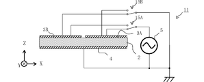
図5は、本実施形態に係る圧電モータ装置11の回路図である。
圧電モータ装置11は、前述の圧電モータ装置1の回路構成に加えて、交流源5の一方側に接続される個別電極を切り替えるスイッチ15Aと、交流源5の他方側に接続される個別電極を切り替えるスイッチ15Bとを備える。
この構成では、交流源5の一方側が個別電極3Aに接続されており、他方側が個別電極3Bと共通電極4とに接続されており、交流源5と個別電極3Bと共通電極4との接続点がグランドに接続されている状態と、交流源5の一方側が個別電極3Bに接続されており、他方側が個別電極3Aと共通電極4とに接続されており、交流源5と個別電極3Aと共通電極4との接続点がグランドに接続されている状態と、を切り替えるようにスイッチ15A,15Bが制御される。
交流源5の一方側が個別電極3Aに接続されており、他方側が個別電極3Bと共通電極4とに接続されており、交流源5と個別電極3Bと共通電極4との接続点がグランドに接続されている状態では、圧電モータ装置11は第1の実施形態の圧電モータ装置1と同じ動作を行う。
一方、交流源5の一方側が個別電極3Bに接続されており、他方側が個別電極3Aと共通電極4とに接続されており、交流源5と個別電極3Aと共通電極4との接続点がグランドに接続されている状態では、圧電モータ装置11は第1の実施形態の圧電モータ装置1とは逆の動作を行い、突起部(不図示)が反時計回りの円軌道または楕円軌道で変位し、リニアスライダ(不図示)をX軸負方向に移動させる。したがって、本実施形態の圧電モータ装置11は、スイッチ15A,15Bの制御により、リニアスライダの移動方向を切り替えることができる。
次に、本発明の第3の実施形態に係る圧電モータ装置12について説明する。
図6は、本実施形態に係る圧電モータ装置12の回路図である。
圧電モータ装置12は、前述の圧電モータ装置1の回路構成に加えて、交流源5Aを備える。すなわち、圧電モータ装置12は、2相電源を有する。交流源5の一方側が個別電極3Aに接続されており、交流源5Aの一方側が個別電極3Bに接続されており、交流源5および交流源5Aの他方側が共通電極4に接続されており、交流源5と交流源5Aと共通電極4との接続点がグランドに接続されている。
この構成では、交流源5から個別電極3Aにsin(ωt)の正弦波信号が印加され、交流源5Aから個別電極3Bにcos(ωt)の正弦波信号が印加されることにより、E(3,1)モードの対称モードと非対称モードとの位相差が90°となるように個別電極3A,3Bと共通電極4との間に交流電圧が印加されることになり、第1の実施形態の圧電モータ装置1と同様に、E(3,1)モードの対称モードと非対称モードとが合成された楕円運動の振動が励振される。よって、圧電モータ装置12は第1の実施形態の圧電モータ装置1と同じ動作を行う。
第1の実施形態の圧電モータ装置1では、個別電極3Bがグランドに接続されているため、交流源は1つでよいものの、E(3,1)モードの対称モードと非対称モードとの位相差が約90°となるのは、特定の周波数に限られる。一方、本実施形態の圧電モータ装置12は、交流源は2つであるが、様々な周波数においてE(3,1)モードの対称モードと非対称モードとの位相差が約90°とすることができる。
以上に説明した実施形態では、動力伝達対象として直線運動するリニアスライダを用いる例を示したが、リニアスライダの他にも回転運動するロータなどを動力伝達対象としてもよい。その場合、ロータの周面を突起部に対向させるように配置することで、圧電モータによりロータを回転させて回転運動の動力を得ることができる。
本発明は以上に説明した実施形態の記載に制限されるものではなく、本発明の範囲は特許請求の範囲によって示される。そして、本発明の範囲には、特許請求の範囲よって示されるものだけでなく特許請求の範囲に均等な範囲で変更された全てのものが含まれる。
1,11,12…圧電モータ装置
2…圧電板
2A…突起部
3A,3B…個別電極
4…共通電極
5,5A…交流源
6…押圧バネ
7…フレーム
8…ベアリング
9…リニアスライダ
15A,15B…スイッチ
2…圧電板
2A…突起部
3A,3B…個別電極
4…共通電極
5,5A…交流源
6…押圧バネ
7…フレーム
8…ベアリング
9…リニアスライダ
15A,15B…スイッチ
Claims (12)
- 互いに隣接する第1の領域と第2の領域とを含む第1の面を有する圧電板と、
前記第1の領域と前記第2の領域との境界線上に設けられ、前記境界線に沿った第1の方向に変位するとともに、前記圧電板の前記第1の面の法線方向と前記第1の方向とに対して垂直な第2の方向に変位する動力伝達部と、
前記第1の領域に設けられた第1の個別電極と、前記第2の領域に設けられた第2の個別電極と、前記圧電板の前記第1の面と対向する第2の面に設けられた共通電極とを含み、前記第1の個別電極と前記共通電極との間に交流電圧を印加するとともに、前記第2の個別電極が浮き電極にならないようにする駆動部と、
を備える圧電モータ。 - 前記駆動部は、一方側が前記第1の個別電極に接続されており、他方側が前記第2の個別電極と前記共通電極とに接続されており、前記第1の個別電極と前記共通電極との間に交流電圧を印加する交流源を含み、
前記第2の個別電極と前記共通電極と前記交流源の他方側とがグランドに接続されている、請求項1に記載の圧電モータ。 - 前記駆動部は、前記第1の個別電極と前記共通電極との間に、振動モードがE(3,1)モードである共振周波数に対応する交流電圧を印加する、請求項2に記載の圧電モータ。
- 前記駆動部は、前記圧電板全体にE(3,1)モードの対称モードの振動と非対称モードの振動とが同時に励振され、E(3,1)モードの対称モードと非対称モードとの位相差が約90°となるように、前記第1の個別電極と前記共通電極との間に交流電圧を印加する、請求項3に記載の圧電モータ。
- 前記駆動部は、前記第1の個別電極又は前記第2の個別電極と前記共通電極との間に交流電圧を印加する交流源を含み、
前記交流源の一方側が前記第1の個別電極に接続されており、他方側が前記第2の個別電極と前記共通電極とに接続されており、前記第2の個別電極と前記共通電極と前記交流源の他方側とがグランドに接続されている状態と、
前記交流源の一方側が前記第2の個別電極に接続されており、他方側が前記第1の個別電極と前記共通電極とに接続されており、前記第1の個別電極と前記共通電極と前記交流源の他方側とがグランドに接続されている状態と、
を切り替えるスイッチを備える、請求項1に記載の圧電モータ。 - 前記駆動部は、前記第1の個別電極又は前記第2の個別電極と前記共通電極との間に、振動モードがE(3,1)モードである共振周波数に対応する交流電圧を印加する、請求項5に記載の圧電モータ。
- 前記駆動部は、前記圧電板全体にE(3,1)モードの対称モードの振動と非対称モードの振動とが同時に励振され、E(3,1)モードの対称モードと非対称モードとの位相差が約90°となるように、前記第1の個別電極又は前記第2の個別電極と前記共通電極との間に交流電圧を印加する、請求項6に記載の圧電モータ。
- 前記駆動部は、一方側が前記第1の個別電極に接続されており、他方側が前記共通電極に接続されており、前記第1の個別電極と前記共通電極との間に交流電圧を印加する第1の交流源と、一方側が前記第2の個別電極に接続されており、他方側が前記共通電極に接続されており、前記第2の個別電極と前記共通電極との間に交流電圧を印加する第2の交流源と、を含み、
前記第1の交流源の他方側と前記第2の交流源の他方側とがグランドに接続されている、請求項1に記載の圧電モータ。 - 前記駆動部は、前記第1の個別電極と前記共通電極との間と、前記第2の個別電極と前記共通電極との間とに、振動モードがE(3,1)モードである共振周波数に対応する交流電圧を印加する、請求項8に記載の圧電モータ。
- 前記駆動部は、前記圧電板全体にE(3,1)モードの対称モードの振動と非対称モードの振動とが同時に励振され、E(3,1)モードの対称モードと非対称モードとの位相差が約90°となるように、前記第1の個別電極と前記共通電極との間と、前記第2の個別電極と前記共通電極との間とに交流電圧を印加する、請求項9に記載の圧電モータ。
- 請求項1ないし請求項10に記載の圧電モータと、
前記圧電板の前記第1の方向側に配置されている動力変換部と、
を備える圧電モータ装置。 - 前記動力変換部は、前記第2の方向を移動方向として移動自在なリニアスライダである、請求項11に記載の圧電モータ装置。
Applications Claiming Priority (2)
| Application Number | Priority Date | Filing Date | Title |
|---|---|---|---|
| JP2011118707 | 2011-05-27 | ||
| JP2011-118707 | 2011-05-27 |
Publications (1)
| Publication Number | Publication Date |
|---|---|
| WO2012165189A1 true WO2012165189A1 (ja) | 2012-12-06 |
Family
ID=47259050
Family Applications (1)
| Application Number | Title | Priority Date | Filing Date |
|---|---|---|---|
| PCT/JP2012/062905 Ceased WO2012165189A1 (ja) | 2011-05-27 | 2012-05-21 | 圧電モータおよび圧電モータ装置 |
Country Status (1)
| Country | Link |
|---|---|
| WO (1) | WO2012165189A1 (ja) |
Cited By (2)
| Publication number | Priority date | Publication date | Assignee | Title |
|---|---|---|---|---|
| WO2016061832A1 (zh) * | 2014-10-22 | 2016-04-28 | 深圳市华星光电技术有限公司 | 裸眼3d液晶显示面板及其驱动方法 |
| CN110912444A (zh) * | 2019-04-08 | 2020-03-24 | 浙江师范大学 | 一种仿生爬行式压电驱动器 |
Citations (2)
| Publication number | Priority date | Publication date | Assignee | Title |
|---|---|---|---|---|
| JP2007538484A (ja) * | 2004-05-18 | 2007-12-27 | フィジック インストゥルメント(ピーアイ)ゲーエムベーハー アンド ツェーオー.カーゲー | 圧電超音波モーター |
| JP2011072131A (ja) * | 2009-09-25 | 2011-04-07 | Taiheiyo Cement Corp | 超音波モータ |
-
2012
- 2012-05-21 WO PCT/JP2012/062905 patent/WO2012165189A1/ja not_active Ceased
Patent Citations (2)
| Publication number | Priority date | Publication date | Assignee | Title |
|---|---|---|---|---|
| JP2007538484A (ja) * | 2004-05-18 | 2007-12-27 | フィジック インストゥルメント(ピーアイ)ゲーエムベーハー アンド ツェーオー.カーゲー | 圧電超音波モーター |
| JP2011072131A (ja) * | 2009-09-25 | 2011-04-07 | Taiheiyo Cement Corp | 超音波モータ |
Cited By (5)
| Publication number | Priority date | Publication date | Assignee | Title |
|---|---|---|---|---|
| WO2016061832A1 (zh) * | 2014-10-22 | 2016-04-28 | 深圳市华星光电技术有限公司 | 裸眼3d液晶显示面板及其驱动方法 |
| GB2545853A (en) * | 2014-10-22 | 2017-06-28 | Shenzhen China Star Optoelect | Naked-eye 3D liquid crystal display panel and driving method therefor |
| GB2545853B (en) * | 2014-10-22 | 2021-02-24 | Shenzhen China Star Optoelect | Naked-eye 3D liquid crystal display panel and driving method for the same |
| CN110912444A (zh) * | 2019-04-08 | 2020-03-24 | 浙江师范大学 | 一种仿生爬行式压电驱动器 |
| CN110912444B (zh) * | 2019-04-08 | 2022-09-27 | 浙江师范大学 | 一种仿生爬行式压电驱动器 |
Similar Documents
| Publication | Publication Date | Title |
|---|---|---|
| CN1639955B (zh) | 转动/移动转换致动器 | |
| JP4261964B2 (ja) | 振動型駆動装置および制御システム | |
| US7932660B2 (en) | Ultrasonic motor | |
| Mukhopadhyay et al. | A brief review on the recent evolution in piezoelectric linear ultrasonic motors | |
| JP2014018027A (ja) | 振動型アクチュエータ、撮像装置、及びステージ | |
| JP2008253078A (ja) | 電気機械変換素子,振動アクチュエータ,振動アクチュエータの駆動装置,レンズ鏡筒及びカメラ | |
| CN102185096B (zh) | 压电驱动器及直线压电马达 | |
| Yang et al. | Longitudinal and bending hybrid linear ultrasonic motor using bending PZT elements | |
| US9705425B2 (en) | Piezoelectric linear motor | |
| US20170214339A1 (en) | Ultrasonic motor | |
| US8299682B2 (en) | Ultrasonic motor | |
| CN102292907A (zh) | 基于有组合谐振器的声学驻波的压电准谐振电机 | |
| JP4830165B2 (ja) | 超音波モータ用振動子 | |
| CN109314176B (zh) | 具有可对角励磁的致动器板的超声波电机 | |
| WO2012165189A1 (ja) | 圧電モータおよび圧電モータ装置 | |
| US20160164436A1 (en) | Driving apparatus and lens driving apparatus having the same | |
| KR101225008B1 (ko) | 초음파모터의 압전진동자 | |
| JP4984673B2 (ja) | 駆動装置 | |
| CN102118118B (zh) | 直线型超声波微电机 | |
| CN104022678B (zh) | 分区激励式三自由度超声电机振子 | |
| CN102810997A (zh) | 减摩驱动式超声电机及其复合式定子组件 | |
| JP2009284759A (ja) | 超音波モータ及び超音波モータ付き電子機器 | |
| JP2005261080A (ja) | アクチュエータ | |
| JP2971971B2 (ja) | 超音波アクチュエータ | |
| KR101641649B1 (ko) | 압전 액츄에이터 및 이를 포함하는 전자기기 |
Legal Events
| Date | Code | Title | Description |
|---|---|---|---|
| 121 | Ep: the epo has been informed by wipo that ep was designated in this application |
Ref document number: 12793076 Country of ref document: EP Kind code of ref document: A1 |
|
| NENP | Non-entry into the national phase |
Ref country code: DE |
|
| 122 | Ep: pct application non-entry in european phase |
Ref document number: 12793076 Country of ref document: EP Kind code of ref document: A1 |
|
| NENP | Non-entry into the national phase |
Ref country code: JP |