WO2012165162A1 - Dental therapy apparatus - Google Patents
Dental therapy apparatus Download PDFInfo
- Publication number
- WO2012165162A1 WO2012165162A1 PCT/JP2012/062653 JP2012062653W WO2012165162A1 WO 2012165162 A1 WO2012165162 A1 WO 2012165162A1 JP 2012062653 W JP2012062653 W JP 2012062653W WO 2012165162 A1 WO2012165162 A1 WO 2012165162A1
- Authority
- WO
- WIPO (PCT)
- Prior art keywords
- laser light
- light source
- repetition frequency
- wavelength
- carious
- Prior art date
Links
Images


Classifications
-
- A—HUMAN NECESSITIES
- A61—MEDICAL OR VETERINARY SCIENCE; HYGIENE
- A61C—DENTISTRY; APPARATUS OR METHODS FOR ORAL OR DENTAL HYGIENE
- A61C1/00—Dental machines for boring or cutting ; General features of dental machines or apparatus, e.g. hand-piece design
- A61C1/0046—Dental lasers
-
- A—HUMAN NECESSITIES
- A61—MEDICAL OR VETERINARY SCIENCE; HYGIENE
- A61C—DENTISTRY; APPARATUS OR METHODS FOR ORAL OR DENTAL HYGIENE
- A61C1/00—Dental machines for boring or cutting ; General features of dental machines or apparatus, e.g. hand-piece design
- A61C1/0007—Control devices or systems
- A61C1/0015—Electrical systems
-
- A—HUMAN NECESSITIES
- A61—MEDICAL OR VETERINARY SCIENCE; HYGIENE
- A61C—DENTISTRY; APPARATUS OR METHODS FOR ORAL OR DENTAL HYGIENE
- A61C3/00—Dental tools or instruments
- A61C3/02—Tooth drilling or cutting instruments; Instruments acting like a sandblast machine
Definitions
- the present invention relates to a dental treatment apparatus.
- the difference frequency generation method two wavelengths lambda 1, lambda 2 and is incident on the nonlinear optical crystal, by satisfying the phase matching condition, a method of generating light of wavelength lambda 3.
- AgGaS 2 silver gallium sulfite
- Nd YAG laser
- Cr forsterite
- a laser wavelength ⁇ 2 : 1.15 to 1.36 ⁇ m
- Non-Patent Document 1 laser light is output under a driving condition of a pulse width of 5 ns and a repetition frequency of 10 Hz, so that the cutting speed of the caries portion is fast and cutting is very likely to occur. Therefore, conversely, there is a possibility of damaging soft tissues in the oral cavity.
- an object of the present invention is to provide a dental treatment apparatus that can perform dental treatment more reliably and less invasively.
- a dental treatment apparatus is a laser light source that outputs a laser beam having a wavelength in the wavelength range of 5.7 ⁇ m to 6.6 ⁇ m, a pulse drive of the laser light source, and an output from the laser light source.
- a control unit that controls at least one of the pulse width and the repetition frequency of the pulsed laser light, and an irradiation optical system for irradiating the tooth including the carious site with the light output from the laser light source.
- the control unit selectively cuts the carious site by controlling at least one of the pulse width and the repetition frequency of the pulsed laser beam.
- a laser light source that outputs laser light having a wavelength in the wavelength range of 5.7 ⁇ m to 6.6 ⁇ m is used.
- the caries site is selectively selected while reducing the influence on a healthy site. Can be cut.
- the control unit drives the laser light source in pulses to control at least one of the pulse width and repetition frequency of the pulsed laser light.
- the cutting conditions for example, cutting speed
- dental treatment can be performed more reliably with minimal invasiveness.
- the control unit includes a first mode in which the laser light source is driven at a repetition frequency slower than a repetition frequency corresponding to the pulse width and the thermal relaxation time shorter than the thermal relaxation time of the irradiation region of the pulsed laser light, and the thermal relaxation time
- the control of the laser light source can be switched between the second mode in which the laser light source is driven at a repetition frequency faster than the repetition frequency corresponding to the long pulse width and the thermal relaxation time.
- the laser light source When the laser light source is driven in the first mode, cutting with a reduced thermal effect is performed.
- the laser light source is driven in the second mode, heat easily diffuses outside the irradiation region of the pulsed laser light output from the laser light source.
- the soft tissue when laser light is irradiated to oral soft tissue such as gums, the soft tissue may be excised. In this case, bleeding occurs, but when the periphery of the irradiated region becomes a certain temperature or more due to the thermal diffusion, the soft tissue is solidified and a hemostatic effect is obtained. Therefore, for example, when cutting the carious site in the first mode, even if the soft tissue around the carious site is damaged, the bleeding from the soft tissue can be stopped by switching to the second mode.
- the laser light source may be a quantum cascade laser. By using the quantum cascade laser, it is possible to reduce the size of the dental treatment apparatus.
- A is drawing which shows the irradiation trace of a healthy tooth sample.
- B is drawing which shows the irradiation trace of a carious tooth sample. It is drawing which shows the experimental result at the time of irradiating a 2 layer structure sample with a laser beam.
- (A) is drawing which shows the irradiation trace cross section of the sample irradiated with the laser beam of wavelength 5.7 micrometer
- (b) shows the irradiation trace cross section of the sample irradiated with the laser beam of wavelength 10.6 micrometer. It is a drawing. It is a schematic diagram which shows schematic structure of an example of the dental treatment apparatus which concerns on other embodiment.
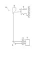
- FIG. 1 is a schematic diagram showing a schematic configuration of an example of a dental treatment apparatus according to an embodiment.
- FIG. 1 also schematically shows a “carious tooth 20” to be treated with the dental treatment apparatus 10A.
- the carious tooth 20 is a tooth having a carious portion (hereinafter simply referred to as “carious portion”) 21 and is a so-called decayed tooth.
- the dental treatment apparatus 10A irradiates a carious tooth 20 as a treatment target with a laser light source 11 that outputs laser light, a control unit 12 that controls driving of the laser light source 11, and a laser light L output from the laser light source 11. And an irradiation optical system 13.
- the dental treatment apparatus 10 ⁇ / b> A may be a tooth processing apparatus that cuts the carious site 21.
- the laser light source 11 is a quantum cascade laser that outputs laser light having a wavelength in the wavelength range of 5.7 ⁇ m to 6.6 ⁇ m.
- the quantum cascade laser is a monopolar type optical waveguide semiconductor laser element that generates light using electronic transition between subbands in a semiconductor quantum well structure.
- a laser light source 11 as a quantum cascade laser includes a semiconductor substrate and an active layer formed on the semiconductor substrate.
- the laser light source 11 has a front end face 11a and a rear end face 11b facing each other, and the front end face 11a and the rear end face 11b constitute an optical resonator.
- the resonator structure (front end face 11a and rear end face 11b) of the laser light source 11 can be formed by cleaving both end faces.
- the configuration and operation of the quantum cascade laser are known (for example, described in JP-A Nos. 2004-247492, 2005-039045, and 2008-177366). The detailed description above is omitted.
- the control unit 12 drives the laser light source 11 in a pulse manner by applying a voltage to the laser light source 11.
- the laser light L output from the laser light source 11 is a pulsed laser light L (hereinafter simply referred to as “pulse laser light L”).
- the control unit 12 can control the pulse width and repetition frequency of the pulsed laser light L output from the laser light source 11 by changing the application state of the voltage applied to the laser light source 11.
- An example of the wavelength of the pulse laser beam L output from the laser light source 11 is 5.75 ⁇ m.
- An example of the pulse width is 10 ns to 1 ms, and an example of the repetition frequency is 500 Hz to 2 MHz.
- the irradiation optical system 13 includes an optical fiber 14 capable of guiding the pulsed laser light L output from the laser light source 11, and an incident for allowing the pulsed laser light L output from the laser light source 11 to enter one end of the optical fiber 14.
- the lens system 15 and the condensing lens system 16 for irradiating the carious tooth 20 with the pulsed laser light L output from the other end of the optical fiber 14 may be provided.
- the configuration of the irradiation optical system 13 is not limited to the configuration using the optical fiber 14, and may be any configuration that can irradiate the treatment target with the laser light L output from the laser light source 11.
- the irradiation optical system 13 may use an articulated light guide as a light guide for guiding light.
- the laser light source 11 and the irradiation optical system 13 are combined in order to optimize optical conditions such as optical axis adjustment. Confirmation of the irradiation position of the pulsed laser beam L having a wavelength in the wavelength range of 5.7 ⁇ m to 6.6 ⁇ m is the same as when using a medical carbon dioxide laser with a wavelength of 10.6 ⁇ m, which is used for medical purposes. be able to.
- the pulsed laser light L having a wavelength in the wavelength range of 5.7 ⁇ m to 6.6 ⁇ m output from the laser light source 11 driven by the control unit 12 is incident on the optical fiber 14 through the incident lens system 15.
- the pulsed laser light L incident on the optical fiber 14 propagates through the optical fiber 14 and is emitted from the other end of the optical fiber 14.
- the pulsed laser light L emitted from the other end of the optical fiber 14 is condensed by the condensing lens system 16 and applied to the carious site 21 of the carious tooth 20.
- the dentist can irradiate the carious part 21 with the pulsed laser light L by operating the irradiation optical system 13 while observing the carious tooth 20.
- a “carious site 21” that is a portion (lesion tissue) to be treated is used.
- the treatment area can be limited.
- Such limitation of the spatial interaction region is considered to be due to the difference in hardness between the carious site 21 and a healthy site (hereinafter referred to as “healthy site”) 22 that is not infected with carious bacteria.
- the wavelength (9 to 10 ⁇ m band) absorbed by the healthy portion 22 from the carious portion 21 cannot be used.
- Biological tissue has a characteristic absorption pattern derived from molecular vibrations in the mid-infrared wavelength region, and in particular, Amide I (the central wavelength of the absorption band is 6.1 ⁇ m) and Amide II (The wavelength corresponding to the center wavelength of the absorption band is 6.45 ⁇ m) is strongly absorbed by the living soft tissue.
- Amide I the central wavelength of the absorption band is 6.1 ⁇ m
- Amide II The wavelength corresponding to the center wavelength of the absorption band is 6.45 ⁇ m
- the nature of the carious part 21 is modified from the healthy part 22 by carious bacteria, and it is considered that the cutting reaction due to the absorption is more likely to occur. Therefore, by using the pulsed laser light L output from the laser light source 11, the carious site 21 can be cut while the influence on the healthy site 22 is further reduced.
- the control unit 12 controls the pulse width and repetition frequency of the pulsed laser light L output from the laser light source 11. Therefore, it is possible to adjust cutting conditions, for example, cutting speed, by controlling the pulse width and the repetition frequency.
- the interaction between the pulsed laser beam L and its irradiation region can be controlled spatially and temporally, so that minimally invasive treatment is possible.
- the pulse state such as the pulse width of the pulsed laser light L is controlled while observing the carious part 21.
- the soft tissue can be treated so as not to be damaged.
- mid-infrared light having a wavelength range of 5.7 ⁇ m to 6.6 ⁇ m gives a thermal action to living tissue.
- This thermal effect can be adjusted by controlling the pulse width (interaction time) and the repetition frequency.
- Thermal relaxation time is important for thermal action.
- the thermal relaxation time of the biological tissue with respect to the laser light having a wavelength range of 5.7 ⁇ m to 6.6 ⁇ m is on the order of ⁇ s. Therefore, by irradiating the pulse laser beam L having a pulse width of ns order (up to about 10 ⁇ s) and a repetition frequency of about 1 to 1000 Hz, the carious site 21 can be cut while suppressing the thermal effect. .
- the pulse laser beam L when a pulse laser beam L having a pulse width on the order of ⁇ s to ms and a repetition frequency of 1000 Hz or more is irradiated, the pulse laser beam L has a strong thermal effect suitable for melting and solidification in the irradiated region. Interaction can be given. Specifically, light with a wavelength in the wavelength range of 5.7 ⁇ m to 6.6 ⁇ m is efficiently absorbed by the protein, so that soft tissue can be excised. In addition, if the conditions satisfy the pulse width longer than the thermal relaxation time of the irradiation region of the pulse laser light L and the short pulse interval, the heat diffuses outside the irradiation region. When the temperature reaches 60 ° C.
- soft tissue can be solidified. Then, coagulation around the excision of the soft tissue can occlude blood vessels and bring about a hemostatic effect.
- This can also be understood from a comparison with a carbon dioxide laser used for medical purposes. That is, when considering the absorption characteristics of living tissue, for example, the absorption coefficient at a wavelength of 5.75 ⁇ m within a wavelength range of 5.7 ⁇ m to 6.6 ⁇ m is about 500 cm ⁇ 1 . This value is almost the same as the absorption coefficient (about 600 cm ⁇ 1 ) for a wavelength of 10.6 ⁇ m of a carbon dioxide laser used for medical purposes. In various medical departments, the coagulation and hemostasis ability of carbon dioxide laser is utilized. Therefore, light having a wavelength similar to that of the carbon dioxide laser (for example, light having a wavelength of 5.75 ⁇ m) can perform soft tissue resection and coagulation hemostasis as described above.
- the dental treatment apparatus 10A having the control unit 12 as a variable mechanism of the pulse width and the repetition frequency is applied not only to cutting the carious site 21 of the carious tooth 20, but also to soft tissue resection and hemostasis. obtain. Since the dental treatment apparatus 10A is capable of hemostasis, even when the carious site 21 near the soft tissue is cut, even if the soft tissue is damaged and bleeding from the soft tissue, the repetition frequency of the pulse laser beam L is increased. It is possible to stop bleeding. Therefore, the optimal therapeutic effect can be obtained by the dental treatment apparatus 10A.
- the dental treatment apparatus 10A can cut the carious site 21 and stop hemostasis etc. with one unit, no other apparatus is required for hemostasis. Therefore, the dentist can effectively treat the teeth by effectively using the treatment room.
- the quantum cascade laser since the quantum cascade laser has a cascade structure in which the light emitting layers are connected in multiple stages, it can output light with higher power. Therefore, by adopting a quantum cascade laser as the laser light source 11, the carious site 21 and the like can be cut more reliably. Further, the quantum cascade laser outputs light having a wavelength range of 5.7 ⁇ m to 6.6 ⁇ m using the quantum well structure intersubband transition, so that, for example, compared with a laser device using a difference frequency generation method, for example. The laser light source 11 is small. Therefore, as described above, the dentist can effectively treat the teeth by effectively using the treatment room.
- the operational effects of the dental treatment apparatus 10A will be described more specifically based on experimental results.
- the experimental conditions such as the wavelength and the pulse state are illustrated for the explanation of the experiment, the present invention is not limited to the wavelength and the pulse state exemplified below.
- FIG. 2 is a schematic diagram showing a schematic configuration of the experimental apparatus.
- the experimental apparatus 30 includes a light source unit 31 that outputs laser light, a three-dimensional stage 32 on which the sample S is mounted, and a laser beam output from the light source unit 31 on the sample S that is mounted on the three-dimensional stage 32.
- a parabolic mirror 33 that emits light, a flat mirror 34 that reflects the laser light output from the light source unit 31 toward the parabolic mirror 33 side, and the light source unit 31 and the flat mirror 34 are arranged, and the light amount of the laser light is reduced.
- an attenuator 35 for adjustment.
- the focal length of the parabolic mirror 33 is about 5 cm. Experimental examples 1 to 4 using the experimental apparatus 30 will be described.
- Example 1 bovine dental healthy dentin was prepared as the healthy tooth sample S1, and decalcified dentin obtained by treating bovine dental dentin with a lactic acid aqueous solution was prepared as the carious tooth sample S2.
- the healthy tooth sample S1 and the carious tooth sample S2 were placed on the three-dimensional stage 32 as the sample S, respectively.
- the light source unit 31 of Experimental Example 1 is a DFG laser having the same configuration as that described in Non-Patent Document 1.
- a laser beam having a predetermined wavelength in the wavelength range of 5.70 to 6.55 ⁇ m was irradiated from the light source unit 31.
- the predetermined wavelength is a wavelength having an interval of 0.05 ⁇ m in the wavelength range.
- the irradiation conditions are as follows. ⁇ Pulse width: 5ns ⁇ Repetition frequency: 10Hz Average power density: 20 W / cm 2 ⁇ Irradiation time: 1 second
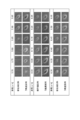
- FIG. 3 is a chart showing the cutting configuration of the healthy tooth sample S1 and the cutting configuration of the carious tooth sample S2 at each wavelength of 0.05 ⁇ m in the wavelength range of 5.70 ⁇ m to 6.55 ⁇ m.
- the carious tooth sample S2 has a larger cutting amount than the healthy tooth sample S1 in the experimental wavelength range. Therefore, laser light having a wavelength in the wavelength range of 5.70 ⁇ m to 6.55 ⁇ m is minimally invasive to a healthy site (or healthy tooth), and can selectively treat a carious site (or carious tooth).
- laser light having a wavelength in the wavelength range of 5.70 ⁇ m to 6.55 ⁇ m is minimally invasive to a healthy site (or healthy tooth), and can selectively treat a carious site (or carious tooth).
- the minimally invasiveness of a laser beam having a wavelength of 5.75 ⁇ m to 5.85 ⁇ m with respect to a healthy site is excellent.
- Example 2 In the same manner as in Experimental Example 1, a healthy tooth sample S1 and a carious tooth sample S2 were prepared.
- the light source unit 31 includes a quantum cascade laser that outputs laser light having a wavelength of 5.75 ⁇ m and a control unit thereof.
- the experimental apparatus 30 of Experimental Example 2 corresponds to the dental treatment apparatus 10 ⁇ / b> A including the plane mirror 34 and the parabolic mirror 33 as the irradiation optical system 13.
- the healthy tooth sample S1 and the carious tooth sample S2 are respectively placed on the three-dimensional stage 32 as the sample S, and the pulse laser light output from the light source unit 31 is applied to the healthy tooth sample S1 and the carious tooth sample S2.
- the irradiation conditions of the pulse laser beam are as follows. ⁇ Pulse width: 500ns ⁇ Repetition frequency: 1 kHz Average power density: 500 W / cm 2 ⁇ Irradiation time: 2 seconds
- the irradiation traces of the healthy tooth sample S1 and the carious tooth sample S2 irradiated with the pulse laser beam were observed with a scanning microscope.
- FIG. 4 (a) is a drawing showing irradiation marks of a healthy tooth sample.
- FIG.4 (b) is drawing which shows the irradiation trace of a carious tooth sample. 4 (a) and 4 (b), it is observed that the carious tooth sample S2 has a larger cutting amount than the healthy tooth sample S1. Further, no cracks were observed on the surface of the healthy tooth sample S1 in which cutting was not observed. Therefore, by using a quantum cascade laser capable of outputting laser light having a wavelength of 5.75 ⁇ m, it is minimally invasive to a healthy site (or healthy tooth) and can selectively treat a carious site (or carious tooth). Can be understood.
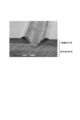
- Example 3 In Experimental Example 3, a two-layer structure sample S4 was prepared in which a carious tooth sample part obtained by treating bovine dentin with a lactic acid aqueous solution was laminated on a healthy tooth sample part.
- the two-layer structure sample S4 was irradiated with pulsed laser light from the light source unit 31 under the same conditions as in Experimental Example 2, except that the sample was replaced with the two-layer structure sample S4.
- the two-layer structure sample S4 was irradiated with pulsed laser light from the carious tooth sample portion side. After irradiating the pulse laser beam, the cross section of the irradiation trace was observed with an optical microscope.
- FIG. 5 is a drawing showing a cross section of an irradiation mark.
- the broken line indicates the caries / healthy boundary. It can be understood from FIG. 5 that the cutting stops at the caries / healthy boundary. Therefore, it was experimentally shown that the laser light having a wavelength of 5.75 ⁇ m reacts with the carious site and does not react with the healthy site.
- Example 4 In Experimental Example 4, a chicken breast was prepared as the biological soft tissue sample S5, and the biological soft tissue sample S5 was placed on the three-dimensional stage 32.
- a pulse laser beam having a wavelength of 5.75 ⁇ m was output from the light source unit 31 including the quantum cascade laser, and the biological soft tissue sample S5 was irradiated with the pulse laser beam.
- the irradiation conditions are as follows. ⁇ Pulse width: 500ns ⁇ Repetition frequency: 1 kHz Average power density: 2500 W / cm 2 ⁇ Irradiation time: 5 seconds
- the light source unit 31 is replaced with a medical carbon dioxide laser device (Lezawin CH S manufactured by Morita Manufacturing Co., Ltd.).
- the biological soft tissue sample S5 was irradiated with CW).
- the irradiation conditions are as follows. Average power density: 2500 W / cm 2 ⁇ Irradiation time: 5 seconds
- the living body soft tissue sample S5 irradiated with the laser beam with the wavelength of 5.75 ⁇ m output from the quantum cascade laser and the living body irradiated with the laser beam with the wavelength of 10.6 ⁇ m output from the medical carbon dioxide laser device.
- the cross section of each irradiation mark of the soft tissue sample S5 was observed with hematoxylin and eosin staining, which is a general histological evaluation method.
- FIG. 6A is a drawing showing a cross section of an irradiation mark of a sample irradiated with a laser beam having a wavelength of 5.75 ⁇ m
- FIG. 6B is an irradiation of the sample irradiated with a laser beam having a wavelength of 10.6 ⁇ m. It is drawing which shows a trace cross section.
- the incision action when using the quantum cascade laser is similar to that when using a medical carbon dioxide laser.
- solidification and carbonization occur, but the degree is smaller in FIG. 6 (a). Therefore, the configuration of the laser light source 11 shown in FIG. 1 can be clinically advantageous from the viewpoint that moderate coagulation and excessive carbonization do not occur.
- the difference between solidification and carbonization is thought to be due to the pulse structure of short pulse and high repetition frequency of quantum cascade laser. Since the balance between the incision action and the coagulation and hemostasis action can be controlled by the variable mechanism (control part 12) of the pulse width and the repetition frequency, the dental treatment including the laser light source 11 and the control part 12 as shown in FIG. Device 10A may also perform advanced soft tissue resection.
- FIG. 7 is a schematic diagram showing a schematic configuration of a dental treatment apparatus according to another embodiment.
- the dental treatment apparatus 10B illustrated in FIG. 7 is different from the dental treatment apparatus 10A illustrated in FIG. 1 in that the control unit 40 includes a mode switching unit 41. Since the configuration other than the control unit 40 is the same as that in the case of FIG. 1, description of those components is omitted.
- the mode switching unit 41 included in the control unit 40 changes the pulse state of the pulsed laser light L having a predetermined wavelength (for example, a wavelength of 5.75 ⁇ m) output from the laser light source 11 into a cutting mode (first mode) and a hemostatic mode (first mode). 2 mode).
- the control unit 40 drives the laser light source 11 that is a quantum cascade laser with a pulse width and a repetition frequency at which the carious site 21 can be cut.
- the control unit 40 drives the laser light source 11 that is a quantum cascade laser with a pulse width and a repetition frequency that allow hemostasis of the soft tissue.
- the pulse width and repetition frequency in each of the cutting mode and the hemostatic mode are defined according to the thermal relaxation time of the irradiation region of the pulse laser beam L.
- the control unit 40 drives the laser light source 11 with a pulse width shorter than the thermal relaxation time and a repetition frequency slower than the repetition frequency corresponding to the thermal relaxation time.
- the control unit 40 drives the laser light source 11 with a pulse width longer than the thermal relaxation time and a repetition frequency faster than the repetition frequency corresponding to the thermal relaxation time.
- examples of the pulse width and repetition frequency for cutting when the thermal relaxation time of the living body with respect to light in the wavelength range of 5.7 to 6.6 ⁇ m is on the order of ⁇ s are 5 ns to 1 ⁇ s and 1 to 1 kHz, respectively.
- examples of the pulse width and repetition frequency for hemostasis when the thermal relaxation time of the living body with respect to light in the wavelength range of 5.7 to 6.6 ⁇ m is on the order of ⁇ s are 1 ⁇ s or more and 1 kHz or more, respectively, or duty
- the ratio may be 50% or more.
- the dental treatment apparatus 10B Since the configuration of the dental treatment apparatus 10B is the same as the configuration of the dental treatment apparatus 10A except that the control unit 40 includes a mode switching unit 41, the dental treatment apparatus 10B includes the dental treatment apparatus 10A and the dental treatment apparatus 10A. It can have the same effect. Since the mode switching unit 41 of the control unit 40 can switch between the cutting mode and the hemostatic mode, switching between the case of cutting and the case of hemostasis is easy. Therefore, even if bleeding occurs from the soft tissue (for example, gingiva G) around the carious site 21 during cutting or the like in the cutting mode, the hemostasis treatment can be performed more reliably and quickly.
- the soft tissue for example, gingiva G
- the laser light source is not limited to the quantum cascade laser, and the laser light source outputs a laser beam having a wavelength in the wavelength range of 5.70 ⁇ m to 6.60 ⁇ m and can control the pulse width and repetition frequency by the control unit. If it is.
- the control unit controls the pulse width and the repetition frequency, but it is sufficient to control at least one of the pulse width and the repetition frequency.
Abstract
Description
Generation)方式の中赤外波長可変レーザ(以下、DFGレーザと称す)を利用した非特許文献1及び非特許文献2記載の技術が知られている。差周波発生方式とは、2種類の波長λ1,λ2を非線形光学結晶に入射し、位相整合条件を満たすことにより、波長λ3の光を発生させる方法である。非特許文献1のDFGレーザでは、非線形光学結晶としてAgGaS2(銀ガリウムサルファイト)を採用し、DFGポンプ光、シグナル光としてそれぞれNd:YAGレーザ(波長λ1:1.064μm)、Cr:forsteriteレーザ(波長λ2:1.15~1.36μm)を採用している。これは、非特許文献2においても同様である。 In recent years, carious teeth, so-called decayed teeth, have been processed using a rotary cutting machine represented by an air turbine or an Er: YAG laser beam having a wavelength of 2.94 μm. Such a technique cannot separate a healthy part that is not caries from a carious part. Therefore, caries treatment tends to depend on the skill of the dentist. Therefore, there is a need for a minimally invasive treatment technique that can selectively process carious sites. One such technology is the difference frequency generation (DFG: Difference-Frequency).
A technology described in Non-Patent
実験例1では、健全歯試料S1としてウシ歯の健全象牙質を準備すると共に、う蝕歯試料S2として乳酸水溶液でウシ歯象牙質を処理した脱灰象牙質を準備した。健全歯試料S1及びう蝕歯試料S2をそれぞれ3次元ステージ32に試料Sとして設置した。実験例1の光源部31は、非特許文献1記載されている構成と同様の構成のDFGレーザとした。 (Experimental example 1)
In Experimental Example 1, bovine dental healthy dentin was prepared as the healthy tooth sample S1, and decalcified dentin obtained by treating bovine dental dentin with a lactic acid aqueous solution was prepared as the carious tooth sample S2. The healthy tooth sample S1 and the carious tooth sample S2 were placed on the three-
・パルス幅:5ns
・繰り返し周波数:10Hz
・平均パワー密度:20W/cm2
・照射時間:1秒 In Experimental Example 1, a laser beam having a predetermined wavelength in the wavelength range of 5.70 to 6.55 μm was irradiated from the
・ Pulse width: 5ns
・ Repetition frequency: 10Hz
Average power density: 20 W / cm 2
・ Irradiation time: 1 second
実験例1と同様にして、健全歯試料S1及びう蝕歯試料S2を準備した。実験例2において、光源部31は、波長5.75μmのレーザ光を出力する量子カスケードレーザとその制御部とを備える。この場合、実験例2の実験装置30は、照射光学系13として平面鏡34及び放物面鏡33とを含む歯科用治療装置10Aに対応する。 (Experimental example 2)
In the same manner as in Experimental Example 1, a healthy tooth sample S1 and a carious tooth sample S2 were prepared. In Experimental Example 2, the
・パルス幅:500ns
・繰り返し周波数:1kHz
・平均パワー密度:500W/cm2
・照射時間:2秒 In Experimental Example 2, the healthy tooth sample S1 and the carious tooth sample S2 are respectively placed on the three-
・ Pulse width: 500ns
・ Repetition frequency: 1 kHz
Average power density: 500 W / cm 2
・ Irradiation time: 2 seconds
実験例3では、健全歯試料部上に、乳酸水溶液でウシ歯象牙質を処理したう蝕歯試料部を積層した2層構造試料S4を準備した。試料を2層構造試料S4に代えた点以外は、実験例2と同様の条件で、光源部31からのパルスレーザ光を2層構造試料S4に照射した。2層構造試料S4には、う蝕歯試料部側からパルスレーザ光が照射された。パルスレーザ光を照射した後、光学顕微鏡によって照射痕断面を観察した。 (Experimental example 3)
In Experimental Example 3, a two-layer structure sample S4 was prepared in which a carious tooth sample part obtained by treating bovine dentin with a lactic acid aqueous solution was laminated on a healthy tooth sample part. The two-layer structure sample S4 was irradiated with pulsed laser light from the
実験例4では、生体軟組織試料S5としてトリ胸肉を準備して、生体軟組織試料S5を3次元ステージ32上に載置した。そして、実験例2,3の場合と同様に量子カスケードレーザを含む光源部31から、波長5.75μmのパルスレーザ光を出力して、そのパルスレーザ光を生体軟組織試料S5に照射した。照射条件は、次の通りである。
・パルス幅:500ns
・繰り返し周波数:1kHz
・平均パワー密度:2500W/cm2
・照射時間:5秒 (Experimental example 4)
In Experimental Example 4, a chicken breast was prepared as the biological soft tissue sample S5, and the biological soft tissue sample S5 was placed on the three-
・ Pulse width: 500ns
・ Repetition frequency: 1 kHz
Average power density: 2500 W / cm 2
・ Irradiation time: 5 seconds
・平均パワー密度:2500W/cm2
・照射時間:5秒 Next, the
Average power density: 2500 W / cm 2
・ Irradiation time: 5 seconds
Claims (3)
- 5.7μm~6.6μmの波長域の波長を有するレーザ光を出力するレーザ光源と、
前記レーザ光源をパルス駆動すると共に、前記レーザ光源から出力されるパルス状のレーザ光のパルス幅及び繰り返し周波数の少なくとも一方を制御する制御部と、
前記レーザ光源から出力された光を、う蝕部位を含む歯に照射するための照射光学系と、
を備え、
前記制御部が前記パルス状のレーザ光の前記パルス幅及び前記繰り返し周波数の少なくとも一方を制御することによって、前記歯に含まれるう蝕部位を選択的に切削する、
歯科用治療装置。 A laser light source that outputs laser light having a wavelength in the wavelength range of 5.7 μm to 6.6 μm;
A controller that drives the laser light source in pulses and controls at least one of a pulse width and a repetition frequency of the pulsed laser light output from the laser light source;
An irradiation optical system for irradiating a tooth including a carious portion with light output from the laser light source;
With
The control unit selectively cuts the carious site included in the teeth by controlling at least one of the pulse width and the repetition frequency of the pulsed laser light,
Dental treatment device. - 前記制御部は、前記パルス状のレーザ光の照射領域の熱緩和時間より短いパルス幅及び前記熱緩和時間に対応する繰り返し周波数より遅い繰り返し周波数で前記レーザ光源を駆動する第1モードと、前記熱緩和時間より長いパルス幅及び前記熱緩和時間に対応する繰り返し周波数より速い繰り返し周波数で前記レーザ光源を駆動する第2モードとの間で、前記レーザ光源の制御を切り換える、請求項1記載の歯科用治療装置。 The controller includes a first mode for driving the laser light source at a pulse width shorter than a thermal relaxation time of the irradiation region of the pulsed laser light and a repetition frequency slower than a repetition frequency corresponding to the thermal relaxation time; The dental control according to claim 1, wherein control of the laser light source is switched between a second mode in which the laser light source is driven at a pulse width longer than a relaxation time and a repetition frequency faster than a repetition frequency corresponding to the thermal relaxation time. Therapeutic device.
- 前記レーザ光源は、量子カスケードレーザである、請求項1又は2記載の歯科用治療装置。 The dental treatment apparatus according to claim 1 or 2, wherein the laser light source is a quantum cascade laser.
Priority Applications (3)
| Application Number | Priority Date | Filing Date | Title |
|---|---|---|---|
| US14/110,837 US10166086B2 (en) | 2011-06-01 | 2012-05-17 | Dental therapy apparatus |
| DE112012002328.5T DE112012002328T5 (en) | 2011-06-01 | 2012-05-17 | Dental treatment device |
| CN201280027064.XA CN103596520B (en) | 2011-06-01 | 2012-05-17 | Gear division therapeutic system |
Applications Claiming Priority (2)
| Application Number | Priority Date | Filing Date | Title |
|---|---|---|---|
| JP2011-123662 | 2011-06-01 | ||
| JP2011123662A JP5849307B2 (en) | 2011-06-01 | 2011-06-01 | Dental treatment device |
Publications (1)
| Publication Number | Publication Date |
|---|---|
| WO2012165162A1 true WO2012165162A1 (en) | 2012-12-06 |
Family
ID=47259025
Family Applications (1)
| Application Number | Title | Priority Date | Filing Date |
|---|---|---|---|
| PCT/JP2012/062653 WO2012165162A1 (en) | 2011-06-01 | 2012-05-17 | Dental therapy apparatus |
Country Status (5)
| Country | Link |
|---|---|
| US (1) | US10166086B2 (en) |
| JP (1) | JP5849307B2 (en) |
| CN (1) | CN103596520B (en) |
| DE (1) | DE112012002328T5 (en) |
| WO (1) | WO2012165162A1 (en) |
Families Citing this family (2)
| Publication number | Priority date | Publication date | Assignee | Title |
|---|---|---|---|---|
| CN107205794A (en) * | 2013-10-09 | 2017-09-26 | 北京大学口腔医学院 | Digital control laser automates tooth preparation method and equipment and tooth positioner |
| KR102219629B1 (en) | 2016-05-06 | 2021-02-23 | 컨버전트 덴탈 인크 | Systems and methods for pulsing and directing a pulsed laser beam to treat dental tissue |
Citations (5)
| Publication number | Priority date | Publication date | Assignee | Title |
|---|---|---|---|---|
| US5403306A (en) * | 1993-06-22 | 1995-04-04 | Vanderbilt University | Laser surgery method |
| JPH1033557A (en) * | 1996-07-19 | 1998-02-10 | Matsushita Electric Ind Co Ltd | Dental gas laser system |
| JP2004261288A (en) * | 2003-02-28 | 2004-09-24 | Japan Science & Technology Agency | HIGH REPETITIVELY PULSED LASER APPARATUS WITH WAVELENGTH RANGE OF 6.1 mum FOR TREATING BIOLOGICAL TISSUE |
| JP2008509755A (en) * | 2004-08-13 | 2008-04-03 | バイオレーズ テクノロジー インコーポレイテッド | Dual pulse width medical laser with preset |
| JP2008526276A (en) * | 2004-12-30 | 2008-07-24 | ミラー,アール.ジェイ.ドウェイン | Laser selective cutting with impulse heat accumulation in the IR wavelength range for direct drive ablation |
Family Cites Families (21)
| Publication number | Priority date | Publication date | Assignee | Title |
|---|---|---|---|---|
| JPH05309101A (en) * | 1992-05-08 | 1993-11-22 | I N R Kenkyusho:Kk | Dental treatment device |
| US5656186A (en) * | 1994-04-08 | 1997-08-12 | The Regents Of The University Of Michigan | Method for controlling configuration of laser induced breakdown and ablation |
| US5720894A (en) * | 1996-01-11 | 1998-02-24 | The Regents Of The University Of California | Ultrashort pulse high repetition rate laser system for biological tissue processing |
| US6083218A (en) * | 1996-07-10 | 2000-07-04 | Trw Inc. | Method and apparatus for removing dental caries by using laser radiation |
| US6270324B1 (en) * | 1999-10-26 | 2001-08-07 | Tuthill Corp. | Positive displacement pump and thrust bearing assembly |
| US7359418B2 (en) * | 2003-02-13 | 2008-04-15 | Hamamatsu Photonics K.K. | Quantum cascade laser |
| US7144247B2 (en) * | 2003-04-25 | 2006-12-05 | Oralum, Llc | Hygienic treatments of structures in body cavities |
| US7310466B2 (en) | 2004-04-08 | 2007-12-18 | Omniguide, Inc. | Photonic crystal waveguides and systems using such waveguides |
| US7349589B2 (en) | 2004-04-08 | 2008-03-25 | Omniguide, Inc. | Photonic crystal fibers and medical systems including photonic crystal fibers |
| AU2005234008A1 (en) * | 2004-04-08 | 2005-10-27 | Omniguide Inc. | Photonic crystal waveguides and systems using such waveguides |
| US7231122B2 (en) | 2004-04-08 | 2007-06-12 | Omniguide, Inc. | Photonic crystal waveguides and systems using such waveguides |
| US7167622B2 (en) | 2004-04-08 | 2007-01-23 | Omniguide, Inc. | Photonic crystal fibers and medical systems including photonic crystal fibers |
| US7331954B2 (en) | 2004-04-08 | 2008-02-19 | Omniguide, Inc. | Photonic crystal fibers and medical systems including photonic crystal fibers |
| JP2009526591A (en) * | 2006-02-17 | 2009-07-23 | ザ プロクター アンド ギャンブル カンパニー | Oral care regimens and equipment |
| US20080086118A1 (en) * | 2006-05-17 | 2008-04-10 | Applied Harmonics Corporation | Apparatus and method for diode-pumped laser ablation of soft tissue |
| US7415050B2 (en) * | 2006-09-18 | 2008-08-19 | Biolase Technology, Inc. | Electromagnetic energy distributions for electromagnetically induced mechanical cutting |
| JP2008197080A (en) * | 2007-02-15 | 2008-08-28 | Tohoku Univ | Tooth decay detection method and device |
| US20090028197A1 (en) * | 2007-07-25 | 2009-01-29 | Daylight Solutions Inc | Fixed wavelength mid infrared laser source with an external cavity |
| JP2010042182A (en) * | 2008-08-18 | 2010-02-25 | Fujifilm Corp | Laser treatment device |
| EA018602B1 (en) * | 2008-08-25 | 2013-09-30 | Лазер Абразив Техноложес, Ллс | Method and apparatus for regeneration of oral cavity tissues |
| JP5235572B2 (en) * | 2008-09-16 | 2013-07-10 | 裕二 三輪 | Optical fiber tip processing method and treatment system for dental laser treatment apparatus |
-
2011
- 2011-06-01 JP JP2011123662A patent/JP5849307B2/en active Active
-
2012
- 2012-05-17 US US14/110,837 patent/US10166086B2/en active Active
- 2012-05-17 CN CN201280027064.XA patent/CN103596520B/en active Active
- 2012-05-17 WO PCT/JP2012/062653 patent/WO2012165162A1/en active Application Filing
- 2012-05-17 DE DE112012002328.5T patent/DE112012002328T5/en active Pending
Patent Citations (5)
| Publication number | Priority date | Publication date | Assignee | Title |
|---|---|---|---|---|
| US5403306A (en) * | 1993-06-22 | 1995-04-04 | Vanderbilt University | Laser surgery method |
| JPH1033557A (en) * | 1996-07-19 | 1998-02-10 | Matsushita Electric Ind Co Ltd | Dental gas laser system |
| JP2004261288A (en) * | 2003-02-28 | 2004-09-24 | Japan Science & Technology Agency | HIGH REPETITIVELY PULSED LASER APPARATUS WITH WAVELENGTH RANGE OF 6.1 mum FOR TREATING BIOLOGICAL TISSUE |
| JP2008509755A (en) * | 2004-08-13 | 2008-04-03 | バイオレーズ テクノロジー インコーポレイテッド | Dual pulse width medical laser with preset |
| JP2008526276A (en) * | 2004-12-30 | 2008-07-24 | ミラー,アール.ジェイ.ドウェイン | Laser selective cutting with impulse heat accumulation in the IR wavelength range for direct drive ablation |
Non-Patent Citations (2)
| Title |
|---|
| KATSUNORI ISHII ET AL.: "Development of Selective Laser Treatment Techniques using Mid-infrared Tunable Nanosecond Pulsed Laser", IEEE ENGINEERING IN MEDICINE AND BIOLOGY SOCIETY, 32ND ANNUAL INTERNATIONAL CONFERENCE, 2010, pages 1614 - 1617 * |
| MASAYUKI SAEKI ET AL.: "Hacho 6.02pm no Nano Byo Pulse Laser ni yoru Dakkai Zogeshitsu no Sentakuteki Setsujo", JOURNAL OF JAPANESE SOCIETY FOR LASER DENTISTRY, vol. 22, no. 1, April 2011 (2011-04-01), pages 16 - 20 * |
Also Published As
| Publication number | Publication date |
|---|---|
| CN103596520A (en) | 2014-02-19 |
| CN103596520B (en) | 2016-05-04 |
| US10166086B2 (en) | 2019-01-01 |
| DE112012002328T5 (en) | 2014-03-20 |
| JP2012249762A (en) | 2012-12-20 |
| JP5849307B2 (en) | 2016-01-27 |
| US20140030671A1 (en) | 2014-01-30 |
Similar Documents
| Publication | Publication Date | Title |
|---|---|---|
| JP2895436B2 (en) | Laser healing equipment | |
| US5290274A (en) | Laser apparatus for medical and dental treatments | |
| Knappe et al. | Principles of lasers and biophotonic effects | |
| KR102433383B1 (en) | Multiple beam laser treatment device | |
| JP2018047315A (en) | System and method for performing endodontic procedures with lasers | |
| US20020002367A1 (en) | Twin light laser | |
| JP2004530477A (en) | Laser treatment method for soft tissue | |
| JPH0453540B2 (en) | ||
| US20070244527A1 (en) | A Treatment Apparatus And a Method of Treatment | |
| JP2004261288A (en) | HIGH REPETITIVELY PULSED LASER APPARATUS WITH WAVELENGTH RANGE OF 6.1 mum FOR TREATING BIOLOGICAL TISSUE | |
| Romanos | Advanced laser surgery in dentistry | |
| JP5849307B2 (en) | Dental treatment device | |
| Palaia et al. | Histological ex vivo evaluation of the suitability of a 976 nm diode laser in oral soft tissue biopsies | |
| JP3577653B2 (en) | Dental gas laser device | |
| Lal et al. | Usefullness of laser in oral and maxillofacial surgery | |
| Romanos | Laser Fundamental Principles | |
| Khan et al. | Diode laser: A novel approach for the treatment of pericoronitis | |
| JP2008167896A (en) | Medical laser apparatus | |
| Nazar et al. | Laser In Oral And Maxillofacial Surgery-Review of Literature | |
| Prabha et al. | An insight into Lasers in Periodontics: A Review. | |
| JP2009515621A (en) | Method of treatment | |
| Frank | Biophysical fundamentals for laser application in medicine | |
| JPH11113923A (en) | Pulse-shaped light source | |
| JP5493325B2 (en) | Laser knife | |
| Girard et al. | Bone surgery with femtosecond laser compared to mechanical instruments: healing studies |
Legal Events
| Date | Code | Title | Description |
|---|---|---|---|
| WWE | Wipo information: entry into national phase |
Ref document number: 201280027064.X Country of ref document: CN |
|
| 121 | Ep: the epo has been informed by wipo that ep was designated in this application |
Ref document number: 12792824 Country of ref document: EP Kind code of ref document: A1 |
|
| WWE | Wipo information: entry into national phase |
Ref document number: 14110837 Country of ref document: US |
|
| WWE | Wipo information: entry into national phase |
Ref document number: 1120120023285 Country of ref document: DE Ref document number: 112012002328 Country of ref document: DE |
|
| 122 | Ep: pct application non-entry in european phase |
Ref document number: 12792824 Country of ref document: EP Kind code of ref document: A1 |