WO2012164924A1 - 動画像符号化装置、動画像符号化方法及び動画像符号化プログラム、並びに動画像復号装置、動画像復号方法及び動画像復号プログラム - Google Patents
動画像符号化装置、動画像符号化方法及び動画像符号化プログラム、並びに動画像復号装置、動画像復号方法及び動画像復号プログラム Download PDFInfo
- Publication number
- WO2012164924A1 WO2012164924A1 PCT/JP2012/003540 JP2012003540W WO2012164924A1 WO 2012164924 A1 WO2012164924 A1 WO 2012164924A1 JP 2012003540 W JP2012003540 W JP 2012003540W WO 2012164924 A1 WO2012164924 A1 WO 2012164924A1
- Authority
- WO
- WIPO (PCT)
- Prior art keywords
- motion vector
- prediction
- prediction block
- block
- picture
- Prior art date
Links
Images


Classifications
-
- H—ELECTRICITY
- H04—ELECTRIC COMMUNICATION TECHNIQUE
- H04N—PICTORIAL COMMUNICATION, e.g. TELEVISION
- H04N19/00—Methods or arrangements for coding, decoding, compressing or decompressing digital video signals
- H04N19/10—Methods or arrangements for coding, decoding, compressing or decompressing digital video signals using adaptive coding
- H04N19/134—Methods or arrangements for coding, decoding, compressing or decompressing digital video signals using adaptive coding characterised by the element, parameter or criterion affecting or controlling the adaptive coding
- H04N19/136—Incoming video signal characteristics or properties
- H04N19/137—Motion inside a coding unit, e.g. average field, frame or block difference
- H04N19/139—Analysis of motion vectors, e.g. their magnitude, direction, variance or reliability
-
- H—ELECTRICITY
- H04—ELECTRIC COMMUNICATION TECHNIQUE
- H04N—PICTORIAL COMMUNICATION, e.g. TELEVISION
- H04N19/00—Methods or arrangements for coding, decoding, compressing or decompressing digital video signals
- H04N19/50—Methods or arrangements for coding, decoding, compressing or decompressing digital video signals using predictive coding
- H04N19/503—Methods or arrangements for coding, decoding, compressing or decompressing digital video signals using predictive coding involving temporal prediction
- H04N19/51—Motion estimation or motion compensation
- H04N19/513—Processing of motion vectors
-
- H—ELECTRICITY
- H04—ELECTRIC COMMUNICATION TECHNIQUE
- H04N—PICTORIAL COMMUNICATION, e.g. TELEVISION
- H04N19/00—Methods or arrangements for coding, decoding, compressing or decompressing digital video signals
- H04N19/50—Methods or arrangements for coding, decoding, compressing or decompressing digital video signals using predictive coding
-
- H—ELECTRICITY
- H04—ELECTRIC COMMUNICATION TECHNIQUE
- H04N—PICTORIAL COMMUNICATION, e.g. TELEVISION
- H04N19/00—Methods or arrangements for coding, decoding, compressing or decompressing digital video signals
- H04N19/70—Methods or arrangements for coding, decoding, compressing or decompressing digital video signals characterised by syntax aspects related to video coding, e.g. related to compression standards
-
- H—ELECTRICITY
- H04—ELECTRIC COMMUNICATION TECHNIQUE
- H04N—PICTORIAL COMMUNICATION, e.g. TELEVISION
- H04N19/00—Methods or arrangements for coding, decoding, compressing or decompressing digital video signals
- H04N19/10—Methods or arrangements for coding, decoding, compressing or decompressing digital video signals using adaptive coding
- H04N19/102—Methods or arrangements for coding, decoding, compressing or decompressing digital video signals using adaptive coding characterised by the element, parameter or selection affected or controlled by the adaptive coding
- H04N19/103—Selection of coding mode or of prediction mode
- H04N19/105—Selection of the reference unit for prediction within a chosen coding or prediction mode, e.g. adaptive choice of position and number of pixels used for prediction
-
- H—ELECTRICITY
- H04—ELECTRIC COMMUNICATION TECHNIQUE
- H04N—PICTORIAL COMMUNICATION, e.g. TELEVISION
- H04N19/00—Methods or arrangements for coding, decoding, compressing or decompressing digital video signals
- H04N19/10—Methods or arrangements for coding, decoding, compressing or decompressing digital video signals using adaptive coding
- H04N19/102—Methods or arrangements for coding, decoding, compressing or decompressing digital video signals using adaptive coding characterised by the element, parameter or selection affected or controlled by the adaptive coding
- H04N19/124—Quantisation
-
- H—ELECTRICITY
- H04—ELECTRIC COMMUNICATION TECHNIQUE
- H04N—PICTORIAL COMMUNICATION, e.g. TELEVISION
- H04N19/00—Methods or arrangements for coding, decoding, compressing or decompressing digital video signals
- H04N19/10—Methods or arrangements for coding, decoding, compressing or decompressing digital video signals using adaptive coding
- H04N19/134—Methods or arrangements for coding, decoding, compressing or decompressing digital video signals using adaptive coding characterised by the element, parameter or criterion affecting or controlling the adaptive coding
- H04N19/157—Assigned coding mode, i.e. the coding mode being predefined or preselected to be further used for selection of another element or parameter
- H04N19/159—Prediction type, e.g. intra-frame, inter-frame or bidirectional frame prediction
-
- H—ELECTRICITY
- H04—ELECTRIC COMMUNICATION TECHNIQUE
- H04N—PICTORIAL COMMUNICATION, e.g. TELEVISION
- H04N19/00—Methods or arrangements for coding, decoding, compressing or decompressing digital video signals
- H04N19/10—Methods or arrangements for coding, decoding, compressing or decompressing digital video signals using adaptive coding
- H04N19/169—Methods or arrangements for coding, decoding, compressing or decompressing digital video signals using adaptive coding characterised by the coding unit, i.e. the structural portion or semantic portion of the video signal being the object or the subject of the adaptive coding
- H04N19/17—Methods or arrangements for coding, decoding, compressing or decompressing digital video signals using adaptive coding characterised by the coding unit, i.e. the structural portion or semantic portion of the video signal being the object or the subject of the adaptive coding the unit being an image region, e.g. an object
- H04N19/172—Methods or arrangements for coding, decoding, compressing or decompressing digital video signals using adaptive coding characterised by the coding unit, i.e. the structural portion or semantic portion of the video signal being the object or the subject of the adaptive coding the unit being an image region, e.g. an object the region being a picture, frame or field
-
- H—ELECTRICITY
- H04—ELECTRIC COMMUNICATION TECHNIQUE
- H04N—PICTORIAL COMMUNICATION, e.g. TELEVISION
- H04N19/00—Methods or arrangements for coding, decoding, compressing or decompressing digital video signals
- H04N19/10—Methods or arrangements for coding, decoding, compressing or decompressing digital video signals using adaptive coding
- H04N19/169—Methods or arrangements for coding, decoding, compressing or decompressing digital video signals using adaptive coding characterised by the coding unit, i.e. the structural portion or semantic portion of the video signal being the object or the subject of the adaptive coding
- H04N19/17—Methods or arrangements for coding, decoding, compressing or decompressing digital video signals using adaptive coding characterised by the coding unit, i.e. the structural portion or semantic portion of the video signal being the object or the subject of the adaptive coding the unit being an image region, e.g. an object
- H04N19/176—Methods or arrangements for coding, decoding, compressing or decompressing digital video signals using adaptive coding characterised by the coding unit, i.e. the structural portion or semantic portion of the video signal being the object or the subject of the adaptive coding the unit being an image region, e.g. an object the region being a block, e.g. a macroblock
-
- H—ELECTRICITY
- H04—ELECTRIC COMMUNICATION TECHNIQUE
- H04N—PICTORIAL COMMUNICATION, e.g. TELEVISION
- H04N19/00—Methods or arrangements for coding, decoding, compressing or decompressing digital video signals
- H04N19/10—Methods or arrangements for coding, decoding, compressing or decompressing digital video signals using adaptive coding
- H04N19/169—Methods or arrangements for coding, decoding, compressing or decompressing digital video signals using adaptive coding characterised by the coding unit, i.e. the structural portion or semantic portion of the video signal being the object or the subject of the adaptive coding
- H04N19/184—Methods or arrangements for coding, decoding, compressing or decompressing digital video signals using adaptive coding characterised by the coding unit, i.e. the structural portion or semantic portion of the video signal being the object or the subject of the adaptive coding the unit being bits, e.g. of the compressed video stream
-
- H—ELECTRICITY
- H04—ELECTRIC COMMUNICATION TECHNIQUE
- H04N—PICTORIAL COMMUNICATION, e.g. TELEVISION
- H04N19/00—Methods or arrangements for coding, decoding, compressing or decompressing digital video signals
- H04N19/50—Methods or arrangements for coding, decoding, compressing or decompressing digital video signals using predictive coding
- H04N19/503—Methods or arrangements for coding, decoding, compressing or decompressing digital video signals using predictive coding involving temporal prediction
- H04N19/51—Motion estimation or motion compensation
- H04N19/513—Processing of motion vectors
- H04N19/517—Processing of motion vectors by encoding
- H04N19/52—Processing of motion vectors by encoding by predictive encoding
Definitions
- the present invention relates to a moving image encoding and decoding technique, and more particularly to a moving image encoding and decoding technique using motion compensated prediction.
- MPEG-4 AVC / H.3 is a typical video compression encoding system.
- H.264 Motion compensation is used in which a picture is divided into a plurality of rectangular blocks, a picture that has already been encoded / decoded is used as a reference picture, and motion from the reference picture is predicted.
- a technique for predicting motion by this motion compensation is called inter prediction.
- MPEG-4 AVC / H. In the inter prediction in H.264, a plurality of pictures can be used as reference pictures, and the most suitable reference picture is selected for each block from the plurality of reference pictures to perform motion compensation. Therefore, a reference index is assigned to each reference picture, and the reference picture is specified by this reference index.
- L0 prediction mainly used as forward prediction
- L1 prediction list 1 prediction
- bi-prediction using two inter predictions of L0 prediction and L1 prediction at the same time is also defined.
- bi-directional prediction is performed, the inter-predicted signals of L0 prediction and L1 prediction are multiplied by a weighting coefficient, an offset value is added and superimposed, and a final inter prediction signal is generated.
- weighting coefficients and offset values used for weighted prediction representative values are set for each reference picture in each list and encoded.
- the encoding information related to inter prediction includes, for each block, a prediction mode for distinguishing between L0 prediction and L1 prediction and bi-prediction, a reference index for specifying a reference picture for each reference list for each block, and a moving direction and a moving amount of the block.
- a prediction process is performed on a motion vector in order to reduce the amount of code of the motion vector generated in each block.
- MPEG-4 AVC / H.264 using the fact that the motion vector to be encoded has a strong correlation with the motion vectors of neighboring neighboring blocks, a prediction motion vector is calculated by performing prediction from neighboring neighboring blocks, and the coding target motion vector is calculated. A difference motion vector that is a difference between the motion vector and the predicted motion vector is calculated, and the difference motion vector is encoded to reduce the amount of codes.
- a median value is calculated from the motion vectors of neighboring blocks A, B, and C in the vicinity to obtain a predicted motion vector, and the difference between the motion vector and the predicted motion vector As a result, the amount of code of the motion vector is reduced (Non-Patent Document 1).
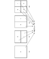
- the shape of the encoding target block and the adjacent block are different as shown in FIG. 48B, when there are a plurality of adjacent blocks on the left side, When there is an adjacent block, the leftmost block is the prediction block, and the encoding target block is divided into 16 ⁇ 8 pixels or 8 ⁇ 16 pixels as shown in FIGS. 48 (c) and 48 (d).
- a prediction block of a reference destination is determined, and prediction is performed from the motion vector of the determined prediction block.
- Non-Patent Document 1 since only one prediction vector is obtained, the prediction accuracy of the prediction motion vector may be lowered depending on the image, and the encoding efficiency may not be improved.
- the present inventors have come to recognize the necessity of further compressing the encoded information and reducing the overall code amount in the image encoding method using motion compensated prediction.
- the present invention has been made in view of such a situation, and an object of the present invention is to calculate a motion vector encoding that improves the encoding efficiency by calculating a prediction motion vector candidate, thereby reducing the code amount of the difference motion vector. And providing a decoding technique. Another object of the present invention is to provide a moving image encoding and decoding technique for improving encoding efficiency by calculating encoding information candidates to reduce the amount of encoded information.
- a moving image encoding device is a moving image encoding device that encodes the moving image using motion compensation in units of blocks obtained by dividing each picture of the moving image.
- a first encoded prediction block adjacent to the encoding target prediction block in the same picture as the encoding target prediction block, and the encoding target prediction in a picture different from the encoding target prediction block Prediction from motion vectors of one of the second encoded prediction blocks located at the same position as or around the block, derive a plurality of motion vector predictor candidates, and derive the motion vector predictor candidates as predicted motion
- a motion vector predictor candidate generation unit 120, 121) to be registered in the vector candidate list and a motion vector predictor selected from the motion vector predictor candidate list That comprises predicted motion vector selection portion (124), encoder for encoding the information indicating the position of the selected prediction motion vector in the motion vector predictor candidate list and (109).
- the motion vector predictor candidate generation unit (120, 121) predicts a motion vector of a prediction block of the first encoded prediction block in order to obtain a set number of motion vector predictor candidates.
- each prediction block in a predetermined order is assigned to each adjacent block group of the left adjacent block group and the upper adjacent block group.
- Condition 1 A motion vector of the same reference picture exists in the same reference list as the encoding mode selected in the encoding target prediction block, Condition 2. 2. a motion vector of the same reference picture exists in a reference list different from the encoding mode selected in the encoding target prediction block; Condition 4.
- a motion vector of a different reference picture exists in the same reference list as the encoding mode selected in the encoding target prediction block.
- the conditions 1 and 2 are prioritized. The process is performed for each prediction block in order, and then the conditions 3 and 4 are performed for each prediction block in the priority order of the conditions 3 and 4.
- Another aspect of the present invention is a video encoding method.
- This method is a moving image coding method for coding the moving image using motion compensation in units of blocks obtained by dividing each picture of the moving image, and the coding target in the same picture as the encoding target prediction block
- the first encoded prediction block adjacent to the prediction block, and the second encoded prediction at the same position as or around the encoding target prediction block in a picture different from the encoding target prediction block A prediction motion vector candidate generating step of predicting from a plurality of motion vectors of the block, deriving a plurality of prediction motion vector candidates, and registering the derived prediction motion vector candidates in a prediction motion vector candidate list;
- a predicted motion vector selection step of selecting a predicted motion vector from the vector candidate list; and the predicted motion vector candidate list
- a coding step of coding the information indicating the position of the selected prediction motion vector definitive is a moving image coding method for coding the moving image using motion compensation in units of blocks obtained by dividing each picture of the moving image,
- a motion vector of which prediction block of the first encoded prediction blocks is selected as a prediction motion vector candidate.
- condition 1 for each prediction block in a predetermined order for each adjacent block group on the left side and the adjacent block group on the upper side .
- a motion vector of the same reference picture exists in the same reference list as the encoding mode selected in the encoding target prediction block, Condition 2.
- a motion vector of the same reference picture exists in a reference list different from the encoding mode selected in the encoding target prediction block; Condition 4.
- a motion vector of a different reference picture exists in the same reference list as the encoding mode selected in the encoding target prediction block.
- the conditions 1 and 2 are prioritized. The process is performed for each prediction block in order, and then the conditions 3 and 4 are performed for each prediction block in the priority order of the conditions 3 and 4.
- a moving picture decoding apparatus is a moving picture decoding apparatus that decodes a coded bit string obtained by coding the moving picture using motion compensation in units of blocks obtained by dividing each picture of the moving picture.
- the first decoded prediction block adjacent to the decoding target prediction block in the same picture as the decoding target prediction block and the decoding target prediction block in a picture different from the decoding target prediction block are located at the same or a peripheral position.
- Predicted motion vector that predicts from any one of the motion vectors of a second decoded prediction block, derives a plurality of predicted motion vector candidates, and registers the derived predicted motion vector candidates in the predicted motion vector candidate list
- the prediction motion vector candidate generation unit (220, 221) obtains a motion vector of which prediction block of the first decoded prediction block in order to obtain a set number of prediction motion vector candidates.
- Condition 2 When determining whether to be a motion vector for deriving a vector candidate with a priority order, for each prediction block in a predetermined order for each adjacent block group on the left adjacent block group and the adjacent block group on the upper side Condition 1 Condition 2.
- a motion vector of the same reference picture exists in the same reference list as that of the encoding mode selected in the decoding target prediction block. 2.
- a motion vector of the same reference picture exists in a reference list different from the encoding mode selected in the decoding target prediction block;
- Condition 4 A motion vector of a different reference picture exists in the same reference list as the encoding mode selected in the decoding target prediction block.
- each reference condition that a motion vector of a different reference picture exists in a reference list different from the encoding mode selected in the decoding target prediction block first, the priority order of the conditions 1 and 2 for the conditions 1 and 2 Then, for each prediction block, the conditions 3 and 4 are performed for each prediction block in the priority order of the conditions 3 and 4.
- Still another aspect of the present invention is a moving picture decoding method.
- This method is a moving picture decoding method for decoding a coded bit sequence in which the moving picture is coded using motion compensation in units of blocks obtained by dividing each picture of the moving picture, and includes the same picture as the prediction target block to be decoded.
- a first decoded prediction block that is adjacent to the decoding target prediction block, and a second decoded prediction that is in the same position as or around the decoding target prediction block in a picture different from the decoding target prediction block A prediction motion vector candidate generating step of predicting from a plurality of motion vectors of the block, deriving a plurality of prediction motion vector candidates, and registering the derived prediction motion vector candidates in a prediction motion vector candidate list; A decoding step for decoding information indicating a position of a predicted motion vector to be selected in the vector candidate list; Based on the information indicating the position of the predicted motion vector to be the selections, and a prediction motion vector selection step of selecting a prediction motion vector from the predicted motion vector candidate list.
- the predictive motion vector candidate generation step derives a predictive motion vector candidate from which the predictive motion vector of the first decoded predictive blocks in order to obtain a set number of predictive motion vector candidates.
- Condition 2. A motion vector of the same reference picture exists in the same reference list as that of the encoding mode selected in the decoding target prediction block. 2. a motion vector of the same reference picture exists in a reference list different from the encoding mode selected in the decoding target prediction block;
- Condition 4 A motion vector of a different reference picture exists in the same reference list as the encoding mode selected in the decoding target prediction block.
- each reference condition that a motion vector of a different reference picture exists in a reference list different from the encoding mode selected in the decoding target prediction block first, the priority order of the conditions 1 and 2 for the conditions 1 and 2 Then, for each prediction block, the conditions 3 and 4 are performed for each prediction block in the priority order of the conditions 3 and 4.
- a plurality of prediction motion vectors are calculated, an optimal prediction motion vector is selected from the plurality of prediction motion vectors, and the amount of generated code of the difference motion vector is reduced, thereby improving the encoding efficiency.
- a plurality of encoding information candidates are calculated, optimal motion information is selected from the plurality of encoding information, and the generated code amount of the encoded information to be transmitted is reduced, Encoding efficiency can be improved.
- FIG. 3 is a block diagram illustrating a detailed configuration of a motion vector calculation unit in FIG. 2. It is a flowchart explaining operation
- movement of the difference motion vector calculation part of FIG. 3 is a flowchart illustrating an operation of a motion vector calculation unit in FIG. 2. It is a flowchart explaining the prediction method of a motion vector. It is a flowchart explaining the prediction motion vector candidate calculation method. It is a flowchart explaining the prediction motion vector candidate calculation method. It is a flowchart explaining the prediction motion vector candidate calculation method. It is a flowchart explaining the prediction motion vector candidate calculation method.
- a plurality of prediction motion vectors are calculated from the motion vectors of the block, and a difference vector between the motion vector of the block to be encoded and the selected prediction motion vector is calculated and encoded, thereby reducing the code amount.
- the amount of code is reduced by estimating the encoding information of the encoding target block by using the encoding information of the surrounding blocks that have already been encoded.
- a plurality of predicted motion vectors are calculated from the motion vectors of the peripheral blocks that have been decoded, and a decoding target is calculated from the difference vector decoded from the encoded stream and the selected predicted motion vector.
- the motion vector of the block is calculated and decoded.
- the encoding information of the decoding target block is estimated by using the encoding information of the peripheral blocks that have been decoded.
- FIG. 1 is a block diagram showing a configuration of a video encoding apparatus according to the embodiment.
- the moving image encoding apparatus according to the embodiment includes an image memory 101, a motion vector detection unit 102, a difference motion vector calculation unit 103, an inter prediction information estimation unit 104, a motion compensation prediction unit 105, a prediction method determination unit 106, a residual signal.
- Generation unit 107, orthogonal transform / quantization unit 108, first encoded bit string generation unit 109, second encoded bit string generation unit 110, multiplexing unit 111, inverse quantization / inverse orthogonal transform unit 112, decoded image signal A superimposing unit 113, an encoded information storage memory 114, and a decoded image memory 115 are provided.
- the image memory 101 temporarily stores image signals to be encoded supplied in order of shooting / display time.
- the image memory 101 supplies the stored image signal to be encoded to the motion vector detection unit 102, the prediction method determination unit 106, and the residual signal generation unit 107 in units of predetermined pixel blocks.
- the images stored in the order of shooting / display time are rearranged in the encoding order and output from the image memory 101 in units of pixel blocks.
- the motion vector detection unit 102 calculates a motion vector for each prediction block size and each prediction mode by block matching or the like between the image signal supplied from the image memory 101 and the decoded image (reference picture) supplied from the decoded image memory 115. Detection is performed in units of prediction blocks, and the detected motion vectors are supplied to the motion compensation prediction unit 105, the difference motion vector calculation unit 103, and the prediction method determination unit 106.
- the prediction block is a unit for performing motion compensation, and details thereof will be described later.
- the difference motion vector calculation unit 103 calculates a plurality of motion vector predictor candidates using the encoded information of the already encoded image signal stored in the encoded information storage memory 114, and puts it in an MVP list to be described later. Registering, selecting an optimal motion vector predictor from a plurality of motion vector predictor candidates registered in the MVP list, calculating a motion vector difference from the motion vector detected by the motion vector detection unit 102 and the motion vector predictor, The calculated difference motion vector is supplied to the prediction method determination unit 106.
- the weighting parameter for weighted prediction of the selected prediction block (weighting to multiply the motion compensation image signal)
- the coefficient value and the weighting offset value to be added) are also supplied to the prediction method determination unit 106.
- the prediction method determination unit 106 is supplied with an MVP index that identifies a prediction motion vector selected from prediction motion vector candidates registered in the MVP list. The detailed configuration and operation of the difference motion vector calculation unit 103 will be described later.
- the inter prediction information estimation unit 104 estimates inter prediction information in merge mode.
- the merge mode is inter prediction information such as a prediction mode of the prediction block, a reference index (information for specifying a reference image used for motion compensation prediction from a plurality of reference images registered in the reference list), a motion vector, and the like. Is a mode in which inter prediction information of an adjacent inter-predicted prediction block that has been encoded or an inter-predicted prediction block of a different image is used.
- a plurality of merge candidates are calculated and registered in a merge candidate list described later
- An optimal merge candidate is selected from a plurality of merge candidates registered in the merge candidate list, and inter prediction information such as a prediction mode, a reference index, and a motion vector of the selected merge candidate is supplied to the motion compensation prediction unit 105.
- a merge index that identifies the selected merge candidate is supplied to the prediction method determination unit 106.
- the weighting parameter for the weighted prediction of the selected merge candidate is also supplied to the motion compensation prediction unit 105.
- a merge index that identifies the selected merge candidate is supplied to the prediction method determination unit 106.
- coding information such as quantization parameters for quantization of the selected coded prediction block can also be used as a predicted value.
- Information is supplied to the prediction method determination unit 106. The detailed configuration and operation of the inter prediction information estimation unit 104 will be described later.
- the motion compensation prediction unit 105 generates a prediction image signal by motion compensation prediction from a reference picture using the motion vectors detected by the motion vector detection unit 102 and the inter prediction information estimation unit 104, and uses the prediction image signal as a prediction method determination unit. 106.
- the unidirectional prediction is performed in the L0 prediction mainly used as the forward prediction and the L1 prediction mainly used as the backward prediction.
- bi-prediction bi-directional prediction is performed, and a weighting factor is adaptively applied to each inter-predicted signal of L0 prediction mainly used as forward prediction and L1 prediction mainly used as backward prediction. Are multiplied, offset values are added and superimposed, and a final predicted image signal is generated.
- weighting parameters including weighting coefficients and offset values used for weighted prediction may be switched in units of pictures, may be switched in units of slices, or may be switched in units of prediction blocks.
- weighting parameter When the weighting parameter is switched in units of pictures or slices, a representative value is set and encoded for each reference picture in each list in units of pictures or slices.
- weighting parameters When switching in units of prediction blocks, weighting parameters are set in units of prediction blocks and encoded.
- the prediction method determination unit 106 evaluates the code amount of the difference motion vector, the amount of distortion between the motion compensated prediction signal and the image signal, and the like, so that an optimum prediction block size (prediction block size) is selected from a plurality of prediction methods. 4 will be described later with reference to FIG. 4), a prediction method such as prediction mode, merge mode or the like is determined, information indicating the determined prediction method, a difference motion vector corresponding to the determined prediction method, and the like Is supplied to the first encoded bit string generation unit 109. It should be noted that the weighted parameter used when performing weighted prediction and the predicted value of the encoded information of the quantization parameter used when performing quantization / inverse quantization are supplied to the first encoded bit string generation unit 109 as necessary. .
- the prediction method determination unit 106 stores information indicating the determined prediction method and encoded information including a motion vector corresponding to the determined prediction method in the encoded information storage memory 114. Note that the weighting parameter for weighted prediction supplied from the prediction method determination unit 106 is stored in the encoded information storage memory 114 as necessary.
- the prediction method determination unit 106 provides a motion compensated prediction image signal corresponding to the determined prediction mode to the residual signal generation unit 107 and the decoded image signal superimposition unit 113.
- the residual signal generation unit 107 generates a residual signal by subtracting the image signal to be encoded and the prediction signal, and supplies the residual signal to the orthogonal transform / quantization unit 108.
- the orthogonal transform / quantization unit 108 performs orthogonal transform and quantization on the residual signal in accordance with the quantization parameter to generate an orthogonal transform / quantized residual signal, and a second encoded bit string generation unit 110 and the inverse quantization / inverse orthogonal transform unit 112. Further, the orthogonal transform / quantization unit 108 stores the quantization parameter in the encoded information storage memory 114.
- the first encoded bit string generation unit 109 encodes encoded information according to the prediction method determined by the prediction method determination unit 106 for each prediction block, in addition to information on a sequence, a picture, a slice, and an encoded block unit.
- a parameter for determining whether or not inter prediction is used a parameter for determining whether or not the mode is merge mode in the case of inter prediction, a merge index in the case of merge mode, a prediction mode, MVP index, and difference motion in the case of not being in merge mode
- Encoding information such as vector information is encoded in accordance with a prescribed syntax rule described later to generate a first encoded bit string, which is supplied to the multiplexing unit 111.
- the merge index mergeIdx can be specified as 0, and is not encoded.
- the MVP index mergeIdx can be specified as 0, so that it is not encoded.
- variable length encoding is performed by assigning a code having a shorter code length to an MVP index having a higher priority in the MVP list (that is, having a lower index number).
- a variable index is assigned by assigning a code having a shorter code length to a merge index having a higher priority in the merge list (that is, a smaller index number).
- the weighting prediction weighting parameter supplied from the prediction method determination unit 106 when not in the merge mode is also encoded.
- the difference between the predicted value of the quantization parameter encoding information for quantization and the value actually used is encoded.
- the second encoded bit string generation unit 110 entropy-encodes the residual signal that has been orthogonally transformed and quantized according to a specified syntax rule to generate a second encoded bit string, and supplies the second encoded bit string to the multiplexing unit 111.
- the multiplexing unit 111 multiplexes the first encoded bit string and the second encoded bit string in accordance with a prescribed syntax rule, and outputs a bit stream.
- the inverse quantization / inverse orthogonal transform unit 112 calculates a residual signal by performing inverse quantization and inverse orthogonal transform on the orthogonal transform / quantized residual signal supplied from the orthogonal transform / quantization unit 108 to perform decoding. This is supplied to the image signal superimposing unit 113.
- the decoded image signal superimposing unit 113 superimposes the prediction signal according to the determination by the prediction method determining unit 106 and the residual signal that has been inversely quantized and inverse orthogonal transformed by the inverse quantization / inverse orthogonal transform unit 112 to generate a decoded image. Generated and stored in the decoded image memory 115.
- the decoded image may be stored in the decoded image memory 115 after filtering processing for reducing distortion such as block distortion due to encoding.
- predicted encoded information such as a flag for identifying information of a post filter such as ALF or a deblocking filter is stored in the encoded information storage memory 114 as necessary.
- FIG. 2 is a block diagram showing a configuration of a moving picture decoding apparatus according to an embodiment corresponding to the moving picture encoding apparatus of FIG.
- the moving picture decoding apparatus includes a separation unit 201, a first encoded bit string decoding unit 202, a second encoded bit string decoding unit 203, a motion vector calculation unit 204, an inter prediction information estimation unit 205, and a motion compensation prediction unit 206.
- the decoding process of the moving picture decoding apparatus in FIG. 2 corresponds to the decoding process provided in the moving picture encoding apparatus in FIG. 1, so the motion compensation prediction unit 206 in FIG.
- the configurations of the inverse orthogonal transform unit 207, the decoded image signal superimposing unit 208, the encoded information storage memory 209, and the decoded image memory 210 are the same as those of the motion compensation prediction unit 105, the inverse quantization / inverse of the moving image encoding device in FIG.
- the orthogonal transform unit 112, the decoded image signal superimposing unit 113, the encoded information storage memory 114, and the decoded image memory 115 have functions corresponding to the respective configurations.
- the bit stream supplied to the separation unit 201 is separated according to a rule of a prescribed syntax, and the separated encoded bit string is supplied to the first encoded bit string decoding unit 202 and the second encoded bit string decoding unit 203.
- the first encoded bit string decoding unit 202 decodes the supplied encoded bit string to obtain sequence, picture, slice, encoded block unit information, and predicted block unit encoded information. Specifically, a parameter for determining whether or not inter prediction, a parameter for determining whether or not inter prediction, a merge index in the merge mode, a prediction mode, an MVP index, a difference motion vector, etc. in the non-merge mode
- the information is decoded according to a prescribed syntax rule to be described later, and the encoded information is supplied to the motion vector calculation unit 204 or the inter prediction information estimation unit 205 and the motion compensation prediction unit 206 and stored in the encoded information storage memory 209.
- the merge index mergeIdx can be specified as 0. Therefore, the encoded bit string is not encoded, and mergeIdx is set to 0. To do. Therefore, in the merge mode, the first encoded bit string decoding unit 202 is supplied with the number of merge candidates registered in the merge candidate list calculated by the inter prediction information estimation unit 205. Similarly, when the mode is not the merge mode, if there is one predicted motion vector candidate registered in the MVP list, which will be described later, the MVP index mvpIdx can be specified as 0, so it is not encoded, and mvpIdx is set to 0. Therefore, when not in the merge mode, the first encoded bit string decoding unit 202 supplies the number of motion vector predictor candidates registered in the MVP list calculated by the motion vector calculation unit 204.
- the second encoded bit string decoding unit 203 calculates a residual signal that has been orthogonally transformed / quantized by decoding the supplied encoded bit string, and dequantized / inverted the residual signal that has been orthogonally transformed / quantized. This is given to the orthogonal transform unit 207.
- the motion vector calculation unit 204 uses the encoded information of the already decoded image signal stored in the encoded information storage memory 209 to generate a plurality of prediction motion vector candidates. Is calculated and registered in an MVP list, which will be described later, and prediction according to the encoded information decoded and supplied by the first encoded bit string decoding unit 202 from among a plurality of motion vector predictor candidates registered in the MVP list A motion vector is selected, a motion vector is calculated from the difference vector decoded by the first encoded bit string decoding unit 202 and the selected predicted motion vector, and is supplied to the motion compensated prediction unit 206, and the encoded information storage memory 209 To supply. Furthermore, the number of predicted motion vector candidates registered in the MVP list calculated by the motion vector calculation unit 204 is supplied to the first encoded bit string decoding unit 202. The detailed configuration and operation of the motion vector calculation unit 204 will be described later.
- the inter prediction information estimation unit 205 estimates the inter prediction information in the merge mode when the prediction block to be decoded is in the merge mode.
- a plurality of merge candidates are calculated and registered in a merge candidate list, which will be described later, using the encoded information of the already decoded prediction block stored in the encoded information storage memory 114, and registered in the merge candidate list.
- a merge candidate corresponding to the merge index decoded and supplied by the first encoded bit string decoding unit 202 is selected from a plurality of merge candidates, and the selected merge candidate prediction mode, reference index, prediction motion vector, etc. are selected.
- the prediction information is supplied to the motion compensation prediction unit 206 and stored in the encoded information storage memory 209.
- the number of merge candidates registered in the merge candidate list calculated by the inter prediction information estimation unit 205 is supplied to the first encoded bit string decoding unit 202.
- the weighting parameter for the weighted prediction of the selected merge candidate is also supplied to the motion compensated prediction unit 206.
- encoded information other than the inter prediction information of the quantization parameter of quantization can also be used as a prediction value. Coding information to be predicted can also be supplied to the prediction method determination unit 106. The detailed configuration and operation of the inter prediction information estimation unit 205 will be described later.
- the motion compensated prediction unit 206 generates a predicted image signal by motion compensation prediction from the reference picture using the motion vector calculated by the motion vector calculation unit 204, and supplies the predicted image signal to the decoded image signal superimposing unit 208.
- a weighted coefficient is adaptively multiplied and superimposed on the two motion compensated prediction image signals of L0 prediction and L1 prediction to generate a final prediction image signal.
- the inverse quantization / inverse orthogonal transform unit 207 performs inverse orthogonal transform and inverse quantization on the orthogonal transform / quantized residual signal decoded by the first encoded bit string decoding unit 202, and performs inverse orthogonal transform / An inverse quantized residual signal is obtained.
- the decoded image signal superimposing unit 208 superimposes the predicted image signal subjected to motion compensation prediction by the motion compensation prediction unit 206 and the residual signal subjected to inverse orthogonal transform / inverse quantization by the inverse quantization / inverse orthogonal transform unit 207.
- the decoded image signal is decoded and stored in the decoded image memory 210.
- the decoded image may be stored in the decoded image memory 210 after filtering processing for reducing block distortion or the like due to encoding is performed on the decoded image.
- the motion vector prediction method according to the embodiment is implemented in the differential motion vector calculation unit 103 of the video encoding device in FIG. 1 and the motion vector calculation unit 204 of the video decoding device in FIG.
- the inside of the screen is equally divided into square units of any same size.
- This unit is defined as a tree block, and is used as a basic unit of address management for specifying an encoding / decoding target block (an encoding target block in encoding and a decoding target block in decoding) in an image.
- the tree block can be divided into four hierarchically in the tree block according to the texture in the screen, and the block can be made smaller in block size if necessary.
- This block is defined as a coding block and is used as a basic unit of processing when performing coding and decoding.
- the tree block is also the maximum size coding block.
- An encoded block having a minimum size that cannot be further divided into four is referred to as a minimum encoded block.
- each prediction block within the coding block a number starting from 0 is assigned to the prediction block existing inside the coding block. This number is defined as the predicted block index puPartIdx.
- the number described in each prediction block of the encoded block in FIG. 4 represents the prediction block index puPartIdx of the prediction block.
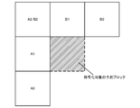
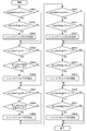
- FIG. 5 is a diagram illustrating a prediction block group adjacent to a prediction block to be encoded / decoded within the same picture as a prediction block to be encoded / decoded.
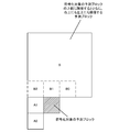
- FIG. 9 illustrates an already encoded / decoded prediction block group that exists at the same position as or near the prediction block to be encoded / decoded in a picture temporally different from the prediction block to be encoded / decoded. It is a figure to do.
- the prediction block group of the present invention will be described with reference to FIGS. 5, 6, 7, 8, and 9.
- a first prediction block group composed of a prediction block A2 adjacent to the upper left of the prediction block to be encoded / decoded is defined as a prediction block group adjacent to the left side.
- the prediction adjacent to the left side is used. If the block A is adjacent to the left side of the prediction block to be encoded / decoded, the prediction block A1 is used. If the block A is adjacent to the lower left side of the prediction block to be encoded / decoded, the prediction block A0 is set. If it is adjacent to the upper left of the target prediction block, the prediction block is A2.
- the lowest is among them. Only the prediction block A10 is included in the prediction block group adjacent to the left side as the prediction block A1 adjacent to the left side. However, only the top prediction block A12 can be included in the prediction block group adjacent to the left side as the prediction block A1 adjacent to the left side, or the lowest prediction block A10 and the top prediction block A12 can be included.
- Both may be included in the prediction block group adjacent on the left side, or all prediction blocks A10, A11, A12 adjacent on the left side may be included in the prediction block group adjacent on the left side.
- a second prediction block group composed of a prediction block B2 (same as the prediction block A2) adjacent to the upper left of the prediction block to be coded / decoded is defined as a prediction block group adjacent to the upper side.
- the prediction adjacent to the upper side according to the above condition. If the block B is adjacent to the upper side of the prediction block to be encoded / decoded, the prediction block B1 is set. If the block B is adjacent to the upper right of the prediction block to be encoded / decoded, the prediction block B0 is set. If it is adjacent to the upper left of the target prediction block, the prediction block is B2.
- the rightmost prediction block B10 is adjacent to the upper side.
- the prediction block B1 to be included is included in the prediction block group adjacent on the upper side.
- only the leftmost prediction block B12 may be included in the prediction block group adjacent to the upper side as the prediction block B1 adjacent to the upper side, or the rightmost prediction block B10 and the leftmost prediction block B12 may be included. Both may be included in the prediction block group adjacent on the left side, or all prediction blocks adjacent on the upper side may be included in the prediction block group adjacent on the upper side.
- prediction block A2 / B2 adjacent to the upper right is included in both the prediction block group adjacent to the left side and the prediction block group adjacent to the left side.
- the prediction block group adjacent to A2 and the upper side is described, it is assumed to be the prediction block B2.
- the prediction block adjacent to the upper left belongs to both the prediction block group adjacent to the left side and the prediction block group adjacent to the upper side, thereby increasing the chance of searching for motion vector predictor candidates.
- the maximum processing amount does not increase, but when importance is placed on reducing the processing amount in serial processing, the prediction block adjacent to the upper left may belong to only one of the groups. .
- a third prediction block group composed of block groups T0, T1, T2, T3, and T4 is defined as a prediction block group at different times.
- a reference picture is designated and referred from a reference index for each reference list LX.
- L0 and L1 are prepared, and X is 0 or 1.
- Inter prediction that refers to a reference picture registered in the reference list L0 is referred to as L0 prediction (Pred_L0)
- motion compensation prediction that refers to a reference picture registered in the reference list L1 is referred to as L1 prediction (Pred_L1).
- L0 prediction is mainly used for forward prediction
- L1 prediction is used for backward prediction.
- (About POC) POC is a variable associated with an image to be encoded, and a value that increases by 1 in the output order is set. Depending on the POC value, it is possible to determine whether the images are the same, to determine the context in the output order, or to determine the distance between images. For example, when the POC of two images have the same value, it can be determined that they are the same image. When the two images have different POC values, it can be determined that the image with the smaller POC value is the image that is output first, and the difference between the POC values of the two images indicates the inter-frame distance.
- a motion vector prediction method is performed in any of the encoding and decoding processes for each prediction block constituting the encoding block.
- inter-picture coding by motion compensation inter prediction
- an encoded motion vector used when calculating a differential motion vector to be coded from a motion vector to be coded is used.
- the prediction motion vector is calculated, in the case of decoding, the prediction motion vector is calculated using the decoded motion vector used when calculating the motion vector to be decoded.
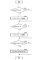
- FIG. 10 shows a first syntax pattern described in the slice header in units of slices of the bitstream generated according to the present invention.
- motion vector candidates of a prediction block at the same position or in the vicinity of a prediction block to be processed in a picture that is different in time direction in a prediction block that is not in inter prediction merge mode have priority Indicates whether or not to be registered in the MVP list to be described later, and in the prediction block in the inter prediction merge mode, the merge candidate at the same position or in the vicinity as the processing target prediction block in the picture that is different in the time direction is given priority.
- a second flag mv_temporal_high_priority_flag indicating whether or not to be registered in the merge candidate list described later is set. This value may be fixed to true (1) or false (0) in order to simplify the determination process described later, but it is more coded by changing adaptively for each frame in order to improve coding efficiency. Reduce the amount.
- the code amount of an MVP index or a merge index described later can be reduced by setting false (0).
- the inter prediction reliability is higher than when the distance is large, and it is determined that the distance is suitable.
- the code amount can be further reduced.
- encoding efficiency can be improved by lowering the priority of the MVP candidates and merge candidates in the time direction by reducing the threshold value X.
- the priority order can be controlled based on statistics in the course of the encoding process.
- mv_temporal_high_priority_flag of the subsequent encoding target image is set to true (1), and when it is small, the distance between the encoding / decoding target image and the reference picture is far By setting false (0), it is possible to reduce the code amount of an MVP index or a merge index, which will be described later.
- a reference list of L0s of pictures including a prediction block to be processed that includes a picture colPic that is different in the temporal direction used in calculating a temporal motion vector predictor candidate or a merge candidate.
- a third flag collocated_from_l0_flag indicating which reference image registered in the L1 reference list is used is set.
- the first indicates whether to change the registration order in the MVP list or merge candidate list described later for each prediction block.
- Four flags mv_list_adaptive_idx_flag are set.
- syntax elements may be installed in a picture parameter set describing syntax elements set in units of pictures.
- the first flag mv_competition_temporal_flag, the second flag mv_temporal_high_priority_flag, the third flag collocated_from_l0_flag, the fourth flag mv_list_adaptive_idx_flag, and the fourth flag mv_list_adaptive_idx_mode are used separately. It can also be controlled independently.
- FIG. 11 shows a syntax pattern described in units of prediction blocks.
- PredMode of the prediction block is MODE_INTER indicating inter-picture prediction (inter prediction)
- merge_flag [x0] [y0] indicating whether the mode is the merge mode is set.
- x0 and y0 are indices indicating the position of the upper left pixel of the prediction block in the screen of the luminance signal
- merge_flag [x0] [y0] is the prediction block located at (x0, y0) in the screen. It is a flag indicating whether or not merge mode.
- merge_flag [x0] [y0] indicates merge mode.
- NumMergeCand exceeds 1, syntax of index of merge list that is a list of predicted motion vector candidates to be referred to.
- An element merge_idx [x0] [y0] is installed.
- x0 and y0 are indices indicating the position of the upper left pixel of the prediction block in the screen
- merge_idx [x0] [y0] is the merge index of the prediction block located at (x0, y0) in the screen. It is.
- the function NumMergeCand represents the number of merge candidates and will be described later.
- merge_idx [x0] [y0] of the index of this merge list is encoded only when the number of merge candidates NumMergeCand is greater than 1, if the total number of motion vector predictor candidates is one. This is because one of them becomes a merge candidate, and the merge candidate to be referred to is determined without transmitting merge_idx [x0] [y0].
- merge_flag [x0] [y0] when merge_flag [x0] [y0] is 0, it indicates that it is not a merge mode.
- a syntax element inter_pred_flag [x0] [y0] for identifying the inter prediction mode is installed.
- a reference picture index syntax element ref_idx_lX [x0] [y0] for specifying a reference picture, a motion vector and a prediction of a prediction block obtained by motion vector detection A syntax element mvd_lX [x0] [y0] [j] of a difference motion vector from the motion vector is installed.
- X is 0 or 1, indicating the prediction direction
- the array index x0 is the x coordinate of the prediction block
- y0 is the y coordinate of the prediction block
- j is the component of the differential motion vector
- j 0 is the x component.
- x0 and y0 are indices indicating the position of the upper left pixel of the prediction block in the screen
- mvp_idx_lX [x0] [y0] is a list of prediction blocks LX located at (x0, y0) in the screen. This is an MVP index.
- the subscript LX represents a reference list, and two L0 and L1 are prepared, and 0 or 1 is entered in X.
- the function NumMVPCand (LX) represents a function for calculating the total number of motion vector predictor candidates for the prediction block in the prediction direction LX (X is 0 or 1), and will be described later.
- the index mvp_idx_lX [x0] [y0] of the MVP list is encoded when the total number of motion vector predictor candidates NumMVPCand (LX) is larger than 1 by the motion vector prediction method. This is because if the total number of prediction motion vector candidates is one, one of them becomes a prediction motion vector, and therefore the reference motion vector candidate to be referred to is determined without transmitting mvp_idx_lX [x0] [y0].
- the motion vector prediction method is a case where inter-picture prediction is performed by motion compensation in units of slices, that is, when the slice type is a P slice (unidirectional prediction slice) or a B slice (bidirectional prediction slice).
- the prediction mode of the prediction block is applied to a prediction block of inter-picture prediction (MODE_INTER).
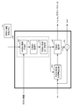
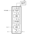
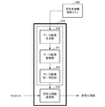
- FIG. 12 is a diagram showing a detailed configuration of the differential motion vector calculation unit 103 of the moving picture encoding device of FIG. A portion surrounded by a thick frame line in FIG. 12 indicates the differential motion vector calculation unit 103.
- the part surrounded by a thick dotted line inside thereof shows an operation unit of a motion vector prediction method described later, and is similarly installed in a video decoding device corresponding to the video encoding device of the embodiment, The same determination result that does not contradict between encoding and decoding can be obtained.
- a motion vector prediction method in encoding will be described with reference to FIG.
- the difference motion vector calculation unit 103 includes a prediction motion vector candidate generation unit 120, a prediction motion vector registration unit 121, a prediction motion vector candidate identity determination unit 122, a prediction motion vector candidate code amount calculation unit 123, a prediction motion vector selection unit 124, and A motion vector subtraction unit 125 is included.
- a difference motion vector of the motion vector used in the inter prediction method selected in the encoding target block is calculated. Specifically, when the encoding target block is L0 prediction, a differential motion vector of the L0 motion vector is calculated, and when the encoding target block is L1 prediction, a differential motion vector of the L1 motion vector is calculated.
- both L0 prediction and L1 prediction are performed, and a differential motion vector of the L0 motion vector and a differential motion vector of the L1 motion vector are calculated.
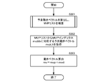
- the motion vector predictor candidate generation unit 120 For each reference list (L0, L1), the motion vector predictor candidate generation unit 120 has a prediction block group adjacent to the upper side (prediction block group adjacent to the left side of the prediction block in the same picture as the prediction block to be encoded: A0, A1, A2 in FIG. 5), a prediction block group adjacent to the left side (prediction block group adjacent to the upper side of the prediction block in the same picture as the prediction block to be encoded: B0, B1, B2 in FIG. 5) , A prediction block group at a different time (a prediction block group that has already been encoded and exists at the same position as or near the prediction block in a picture temporally different from the prediction block to be encoded: T0 in FIG.
- One motion is predicted for each prediction block group from the three prediction block groups T1, T2, and T3).
- mvLXA and mvLXB are called spatial motion vectors
- mvLXCol is called a temporal motion vector.
- These prediction motion vector candidates mvLXA, mvLXB, and mvLXCol may be calculated by scaling according to the relationship between the POC of the encoding target image and the POC of the reference picture.
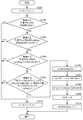
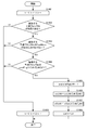
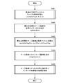
- the motion vector predictor candidate generation unit 120 performs a later-described condition determination on the prediction blocks in each prediction block group in a predetermined order for each prediction block group.
- a motion vector is selected and set as prediction motion vector candidates mvLXA, mvLXB, and mvLXCol.
- the prediction block group adjacent to the left side is adjacent to the upper side in the order from the bottom to the top (order A0 to A0, A1, A2 in FIG. 5).
- prediction block groups at different times in the order from the right to the left of the prediction block group adjacent on the upper side order from B0 to B0, B1, B2 in FIG. 5.
- a condition determination described later is performed for each prediction block in the order of T0 to T0, T1, T2, and T3 in FIG.
- a motion vector is selected, and candidate motion vector predictors are mvLXA, mvLXB, and mvLXCol, respectively.
- the lowest prediction block has the highest priority, and the priority is given from the bottom to the top.
- the rightmost prediction block Blocks have the highest priority and are prioritized from right to left.
- the prediction block of T0 has the highest priority, and the priority is given in the order of T0, T1, T2, and T3.
- the priority order based on the position of this prediction block is defined as priority order A.
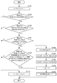
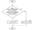
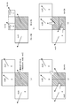
- Condition determination 1 Prediction using the same reference index, that is, a reference frame, is performed in the adjacent prediction block with the same reference list as the motion vector of the difference motion vector calculation target of the prediction block of encoding / decoding target.
- Condition determination 2 Although the reference list is different from the motion vector of the difference motion vector calculation target of the prediction block to be encoded / decoded, prediction using the same reference frame is performed in the adjacent prediction block.
- Condition determination 3 Prediction using the same reference list as the motion vector of the difference motion vector calculation target of the prediction block of the encoding / decoding target and using a different reference frame is performed in the adjacent prediction block.
- Condition determination 4 Prediction using a different reference frame in a reference list that is different from a motion vector that is a difference motion vector calculation target of a prediction block that is an encoding / decoding target is performed in an adjacent prediction block.
- priority order B This priority order is designated as priority order B. If any of these conditions is met, it is determined that there is a motion vector that matches the condition in the prediction block, and the subsequent condition determination is not performed. Note that when the condition of condition determination 1 or condition determination 2 is met, the motion vector of the corresponding adjacent prediction block corresponds to the same reference frame, so that it is used as a predicted motion vector candidate as it is. If the condition of condition determination 4 is met, the motion vector of the corresponding adjacent prediction block corresponds to a different reference frame. Therefore, the motion vector is calculated by scaling based on the motion vector as a candidate for the motion vector predictor.
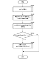
- condition determination of each adjacent prediction block is processed in series instead of in parallel, in the condition determination of the second prediction block group to be performed second (if the condition determination of the left adjacent prediction block group is first, the upper adjacent In the condition determination of the prediction block group), when the motion vector predictor candidate of the prediction block group has the same value as the motion vector predictor candidate determined in the previous prediction block group, the motion vector predictor candidate is not adopted.
- the next condition determination may be performed.
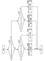
- the following four methods can be set as a method of looping scanning of the spatial prediction block, depending on the above four condition determination methods.
- the appropriateness of the prediction vector and the maximum processing amount differ depending on each method, and these are selected and set in consideration of them. Only method 1 will be described in detail later with reference to the flowcharts of FIGS. 17 to 21. For other methods 2 to 4, those skilled in the art will follow the procedure for carrying out method 1 for the procedure for carrying out method 2 to 4. Since this is a matter that can be designed accordingly, detailed description is omitted.
- the loop process of the scan of the spatial prediction block in a moving image encoder is demonstrated here, it cannot be overemphasized that a similar process is also possible in a moving image decoder.
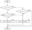
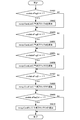
- Method 1 Of the four condition determinations, one condition determination is performed for each prediction block. If the condition is not satisfied, the process proceeds to the condition determination for the adjacent prediction block. The process ends after four rounds of condition determination for each prediction block. Specifically, the condition determination is performed in the following priority order.
- N is A or B
- Condition determination 1 of the prediction block N0 (same reference list, same reference frame) 2.
- Condition determination 1 of the prediction block N1 (same reference list, same reference frame) 3.
- Prediction block N2 condition determination 1 (same reference list, same reference frame) 4).
- Prediction block N0 condition determination 2 (different reference list, same reference frame) 5.
- Prediction block N1 condition determination 2 (different reference list, same reference frame) 6).
- Prediction block N2 condition determination 2 (different reference list, same reference frame) 7.
- Prediction block N0 condition determination 3 (same reference list, different reference frames) 8).
- Condition determination 3 of the prediction block N1 (same reference list, different reference frames) 9.
- Prediction block N2 condition decision 3 (same reference list, different reference frames) 10.
- Prediction block N0 condition determination 4 (different reference list, different reference frame) 11.
- Prediction block N1 condition determination 4 (different reference list, different reference frame) 12
- Prediction block N2 condition determination 4 (different reference list, different reference frame) According to the method 1, since an unscaled predicted motion vector using the same reference frame is easily selected, there is an effect that a possibility that the code amount of the difference motion vector becomes small is increased.
- Method 2 Prioritizing the determination of the unscaled motion vector predictor using the same prediction frame, two condition determinations are performed for each prediction block among the four condition determinations. If the condition is not satisfied, the process proceeds to the condition determination for the next prediction block.
- Condition determination 1 and condition determination 2 are performed in the first round, and condition determination 3 and condition determination 4 are performed in the next round of prediction blocks. Specifically, the condition determination is performed in the following priority order. (However, N is A or B) 1.
- Condition determination 1 of the prediction block N0 (same reference list, same reference frame) 2.
- Prediction block N0 condition determination 2 (different reference list, same reference frame) 3.
- Condition determination 1 of the prediction block N1 (same reference list, same reference frame) 4).
- Prediction block N1 condition determination 2 (different reference list, same reference frame) 5.
- Prediction block N2 condition determination 1 (same reference list, same reference frame) 6).
- Prediction block N2 condition determination 2 (different reference list, same reference frame) 7.
- Prediction block N0 condition determination 3 (same reference list, different reference frames) 8).
- Prediction block N0 condition determination 4 (different reference list, different reference frame) 9.
- Condition determination 3 of the prediction block N1 (same reference list, different reference frames) 10.
- Prediction block N1 condition determination 4 (different reference list, different reference frame) 11.
- Prediction block N2 condition decision 3 (same reference list, different reference frames) 12 Prediction block N2 condition determination 4 (different reference list, different reference frame)
- the method 2 similarly to the method 1, an unscaled predicted motion vector using the same reference frame is easily selected, so that there is an effect that the possibility that the code amount of the difference motion vector becomes small increases.
- the maximum number of rounds for condition determination is two, the number of memory accesses to the encoded information of the prediction block is smaller than that in Method 1 when considering implementation in hardware, and complexity is reduced.
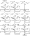
- Method 3 In the first round, the condition determination of condition determination 1 is performed for each prediction block, and if the condition is not satisfied, the process proceeds to the condition determination of the adjacent prediction block. In the next lap, condition determination is performed in order of condition determination 2, condition determination 3 and condition determination 4 for each prediction block, and then the process proceeds to the next. Specifically, the condition determination is performed in the following priority order.
- N is A or B
- Condition determination 1 of the prediction block N0 (same reference list, same reference frame) 2.
- Condition determination 1 of the prediction block N1 (same reference list, same reference frame) 3.
- Prediction block N2 condition determination 1 (same reference list, same reference frame) 4).
- Prediction block N0 condition determination 2 (different reference list, same reference frame) 5.
- Prediction block N0 condition determination 3 (same reference list, different reference frames) 6).
- Prediction block N0 condition determination 4 (different reference list, different reference frame) 7.
- Prediction block N1 condition determination 2 (different reference list, same reference frame) 8).
- Condition determination 3 of the prediction block N1 (same reference list, different reference frames) 9.
- Prediction block N1 condition determination 4 (different reference list, different reference frame) 10.
- Prediction block N2 condition determination 2 (different reference list, same reference frame) 11.
- Prediction block N2 condition decision 3 (same reference list, different reference frames) 12 Prediction block N2 condition determination 4 (different reference list, different reference frame) According to the method 3, since an unscaled predicted motion vector using the same reference frame in the same reference list is easily selected, there is an effect that the possibility that the code amount of the difference motion vector becomes small increases. In addition, since the maximum number of rounds for condition determination is two, the number of memory accesses to the encoded information of the prediction block is smaller than that in Method 1 when considering implementation in hardware, and complexity is reduced.
- Method 4 Priority is given to the condition determination of the same prediction block, and four condition determinations are performed within one prediction block. If all the conditions are not met, it is determined that there is no motion vector matching the condition in the prediction block. The condition of the next prediction block is determined. Specifically, the condition determination is performed in the following priority order. (However, N is A or B) 1. Condition determination 1 of the prediction block N0 (same reference list, same reference frame) 2. Prediction block N0 condition determination 2 (different reference list, same reference frame) 3. Prediction block N0 condition determination 3 (same reference list, different reference frames) 4). Prediction block N0 condition determination 4 (different reference list, different reference frame) 5. Condition determination 1 of the prediction block N1 (same reference list, same reference frame) 6).
- Prediction block N1 condition determination 2 (different reference list, same reference frame) 7. Condition determination 3 of the prediction block N1 (same reference list, different reference frames) 8).
- Prediction block N1 condition determination 4 (different reference list, different reference frame) 9.
- Prediction block N2 condition determination 1 (same reference list, same reference frame) 10.
- Prediction block N2 condition determination 2 (different reference list, same reference frame) 11.
- Prediction block N2 condition decision 3 (same reference list, different reference frames) 12
- Prediction block N2 condition determination 4 (different reference list, different reference frame) According to method 4, the number of rounds for condition determination is at most one, so that the number of memory accesses to the encoded information of the prediction block is considered as method 1, method 2, and method 3 when implementation in hardware is taken into consideration. And complexity is reduced.
- Method 5 As in method 4, prioritizing condition determination for the same prediction block, if four condition determinations are made within one prediction block and all the conditions are not met, there is a motion vector that matches the conditions in the prediction block. It is determined that it does not, and the condition of the next prediction block is determined. However, in the condition determination in the prediction block, method 4 gives priority to the same reference frame, but method 5 gives priority to the same reference list. Specifically, the condition determination is performed in the following priority order. (However, N is A or B) 1. Condition determination 1 of the prediction block N0 (same reference list, same reference frame) 2. Prediction block N0 condition determination 3 (same reference list, different reference frames) 3. Prediction block N0 condition determination 2 (different reference list, same reference frame) 4).
- Prediction block N0 condition determination 4 (different reference list, different reference frame) 5.
- Condition determination 1 of the prediction block N1 (same reference list, same reference frame) 6).
- Condition determination 3 of the prediction block N1 (same reference list, different reference frames) 7.
- Prediction block N1 condition determination 2 (different reference list, same reference frame) 8).
- Prediction block N1 condition determination 4 (different reference list, different reference frame) 9.
- Prediction block N2 condition determination 1 (same reference list, same reference frame) 10.
- Prediction block N2 condition decision 3 (same reference list, different reference frames) 11.
- Prediction block N2 condition determination 2 (different reference list, same reference frame) 12
- Prediction block N2 condition determination 4 (different reference list, different reference frame)
- the reference block reference count can be reduced as compared with the method 4
- the complexity can be reduced by reducing the number of times of access to the memory and the amount of processing such as condition determination. Can do.
- the number of rounds for condition determination is at most 1. Therefore, when considering implementation in hardware, the number of times of memory access to the encoded information of the prediction block is method 1, method 2, Compared to method 3, the complexity is reduced.
- the motion vector predictor registration unit 121 evaluates the priorities of the motion vector candidates mvLXA, mvLXB, and mvLXCol, and stores them in the MVP list mvpListLX in the order corresponding to the priorities.
- the procedure for storing in the MVP list mvpListLX will be described in detail later.
- the motion vector predictor candidate determination unit 122 determines the motion vector predictor candidates having the same motion vector value from the motion vector predictor candidates stored in the MVP list mvpListLX, and determines that they have the same motion vector value.
- the MVP list mvpListLX is updated by leaving one of the predicted motion vector candidates and deleting the others from the MVP list mvpListLX so that the predicted motion vector candidates do not overlap.
- the motion vector predictor candidate identity determination unit 122 provides the updated MVP list mvpListLX to the motion vector predictor candidate code amount calculation unit 123 and the motion vector predictor selection unit 124.
- the motion vector detection unit 102 in FIG. 1 detects the motion vector mv for each prediction block.
- the motion vector mv is input to the predicted motion vector candidate code amount calculation unit 123 together with the predicted motion vector candidates of the updated MVP list mvpListLX.
- the motion vector predictor candidate code amount calculation unit 123 calculates each motion vector difference that is a difference between the motion vector mv and each motion vector candidate mvpListLX [i] stored in the MVP list mvpListLX.
- the code amount when the motion vector is encoded is calculated for each element of the MVP list mvpListLX and supplied to the predicted motion vector selection unit 124.
- the predicted motion vector selection unit 124 selects, as the predicted motion vector mvp, a predicted motion vector candidate mvpListLX [i] that has the smallest code amount for each predicted motion vector candidate among the elements registered in the MVP list mvpListLX.
- the motion vector candidate mvpListLX [ i] is selected as the optimal prediction motion vector mvp.
- the motion vector predictor selection unit 124 also outputs the encoding information used in the prediction block in the MVP list indicated by mvp_idx to the prediction method determination unit 106 in FIG. 1 as necessary.
- the encoding information output here includes a weighting parameter for weighted prediction, a quantization parameter for quantization, and the like.
- the motion vector subtraction unit 125 calculates the differential motion vector mvd by reducing the production of the predicted motion vector mvp selected from the motion vector mv, and outputs the differential motion vector mvd.
- mvd mv ⁇ mvp
- the motion compensation prediction unit 105 refers to the decoded image stored in the decoded image memory 115, performs motion compensation according to the motion vector mv supplied from the motion vector detection unit 102, and performs motion compensation prediction. A signal is obtained and supplied to the prediction method determination unit 106.
- the prediction method determination unit 106 determines a prediction method.
- the code amount and the coding distortion are calculated for each prediction mode, and the prediction block size and the prediction mode for the smallest generated code amount and coding distortion are determined.
- the difference motion vector mvd supplied from the motion vector subtraction unit 125 of the difference motion vector calculation unit 103 and the index mvp_idx representing the prediction motion vector supplied from the prediction motion vector selection unit 124 are encoded, and the code amount of the motion information Is calculated. Further, the code amount of the prediction residual signal obtained by encoding the prediction residual signal between the motion compensation prediction signal supplied from the motion compensation prediction unit 105 and the image signal to be encoded supplied from the image memory 101 is calculated. .
- the total generated code amount obtained by adding the code amount of the motion information and the code amount of the prediction residual signal is calculated and used as the first evaluation value.
- the encoding distortion is calculated as a ratio representing an error from the original image caused by the encoding.
- the prediction block size and the prediction mode that generate the least generated code amount and the coding distortion are determined.
- the motion vector prediction method described above is performed on the motion vector mv corresponding to the prediction mode of the determined prediction block size, and the index representing the prediction motion vector is represented by a second syntax pattern in units of prediction blocks. Is encoded as a flag mvp_idx_lX [i].
- the generated code amount calculated here is preferably a simulation of the encoding process, but can be approximated or approximated easily.
- FIG. 10 shows a first syntax pattern described in the slice header in units of slices of the bit stream generated by the moving picture encoding apparatus of the present invention and decoded by the first encoded bit string decoding unit 202. From the flags described in the slice header of the bitstream, when the slice type is P or B, not only the motion vector of the neighboring prediction block adjacent in the same picture in the prediction block that is not in the inter prediction merge mode.
- Inter prediction is performed using not only the encoding information of neighboring prediction blocks in the same picture but also the encoding information of the prediction block at the same position or in the vicinity of the processing target prediction block in a picture that is different in the time direction.
- First flag mv_competit indicating whether to perform When on_temporal_flag is decoded and mv_competition_temporal_flag is true (1), in a prediction block that is not in inter prediction merge mode, not only motion vectors of neighboring prediction blocks in the same picture but also different pictures in the temporal direction are processed.
- the motion vector is predicted using the prediction block at the same position or in the vicinity of the prediction block, and in the prediction block in the inter prediction merge mode, not only the coding information of the neighboring prediction blocks adjacent in the same picture.
- inter prediction is performed using also the encoding information of the prediction block at the same position or in the vicinity of the prediction block to be processed in pictures different in the time direction.
- mv_competition_temporal_flag when mv_competition_temporal_flag is true (1), in a prediction block that is not in the inter prediction merge mode, motion vector candidates of a prediction block at the same position as a processing target prediction block in a picture different in time direction have priority.
- the second flag mv_temporal_high_priority_flag indicating whether or not to be registered in a merge candidate list, which will be described later, is decoded and determined. If true (1), the prediction block to be processed is the same position as the processing target prediction block in a temporally different picture.
- the motion vector of the prediction block and the merge candidate are registered in the MVP list and the merge candidate list with higher priority.
- a reference list of L0s of pictures including a prediction block to be processed that includes a picture colPic that is different in the temporal direction used in calculating a temporal motion vector predictor candidate or a merge candidate.
- the third flag collocated_from_10_flag indicating which reference image registered in the L1 reference list is used is decoded, and either L0 or L1 is used in the reference picture list of the picture including the prediction block to be processed. Determine whether to do.
- the MVP list described later or the fourth flag mv_list_adaptive_idx_flag indicating whether or not the registration order in the merge candidate list is adaptively changed for each prediction block is decoded, and the MVP list Alternatively, it is determined whether the registration order in the merge candidate list is adaptively changed for each prediction block.
- syntax elements may be installed in a picture parameter set describing syntax elements set in units of pictures.
- the first flag mv_competition_temporal_flag, the second flag mv_temporal_high_priority_flag, the third flag collocated_from_l0_flag, the fourth flag mv_list_adaptive_idx_flag, and the fourth flag mv_list_adaptive_idx_mode are used separately. It can also be controlled independently.
- FIG. 11 shows a second syntax pattern described by the prediction block unit of the bit stream generated by the moving image encoding apparatus of the present invention and decoded by the first encoded bit string decoding unit 202.
- the syntax pattern described in a prediction block unit is shown.
- merge_flag [x0] [y0] indicating whether the prediction mode is merge mode is decoded.
- x0 and y0 are indices indicating the position of the upper left pixel of the prediction block in the screen
- merge_flag [x0] [y0] is the merge mode of the prediction block located at (x0, y0) in the screen. It is a flag indicating whether or not.
- merge_flag [x0] [y0] 1
- the syntax element merge_idx of the index of the merge list that is a list of predicted motion vector candidates to be referred to.
- [X0] [y0] is decoded.
- x0 and y0 are indices indicating the position of the upper left pixel of the prediction block in the screen
- merge_idx [x0] [y0] is the merge index of the prediction block located at (x0, y0) in the screen. It is.
- the syntax element mvp_idx_lX [x0] [y0] of the index of the MVP list that is a list of motion vector predictor candidates to be referred to is decoded.
- x0 and y0 are indices indicating the position of the upper left pixel of the prediction block in the screen
- mvp_idx_lX [x0] [y0] is a list of prediction blocks LX located at (x0, y0) in the screen. This is an MVP index.
- the subscript LX represents a reference list, and two L0 and L1 are prepared, and 0 or 1 is entered in X.
- the function NumMVPCand (LX) represents a function for calculating the total number of motion vector predictor candidates for the prediction block in the prediction direction LX (X is 0 or 1), and will be described later.
- the index mvp_idx_lX [x0] [y0] of this MVP list is decoded when the total number of predicted motion vector candidates NumMVPCand (LX) is greater than 1 by the motion vector prediction method. This is because if the total number of prediction motion vector candidates is one, one of them becomes a prediction motion vector, and therefore the reference motion vector candidate to be referred to is determined without transmitting mvp_idx_lX [x0] [y0].
- FIG. 13 is a diagram illustrating a detailed configuration of the motion vector calculation unit 204 of the video decoding device of FIG. 2 corresponding to the video encoding device of the embodiment.
- a portion surrounded by a thick frame line in FIG. 13 indicates the motion vector calculation unit 204.
- the part surrounded by the thick dotted line inside shows the operation part of the motion vector prediction method described later, which is also installed in the corresponding moving picture coding apparatus in the same way and has the same consistency between coding and decoding. Judgment results are obtained.
- a motion vector prediction method in decoding will be described with reference to FIG.
- the motion vector calculation unit 204 includes a predicted motion vector candidate generation unit 220, a predicted motion vector registration unit 221, a predicted motion vector candidate identity determination unit 222, a predicted motion vector selection unit 223, and a motion vector addition unit 224.
- the predicted motion vector candidate generation unit 220, the predicted motion vector registration unit 221 and the predicted motion vector candidate identity determination unit 222 in the motion vector calculation unit 204 are the predicted motion vector candidates in the differential motion vector calculation unit 103 on the encoding side.
- the generation unit 120, the predicted motion vector registration unit 121, and the predicted motion vector candidate identity determination unit 122 are defined to perform the same operation, the same predicted motion vector candidates that are consistent in encoding and decoding are encoded. And on the decoding side.
- the motion vector predictor candidate generation unit 220 performs the same processing as that of the motion vector predictor candidate generation unit 120 on the encoding side in FIG.
- the motion vector predictor candidate generation unit 220 decodes and records the decoded prediction block adjacent to the decoding target block in the same picture as the decoding target block and the decoding target in a different picture, which are recorded in the encoded information storage memory 209.
- a motion vector such as a decoded prediction block existing at the same position as the block or in the vicinity thereof is read from the encoded information storage memory 209.
- At least one or more motion vector candidates mvLXA, mvLXB, and mvLXCol are generated from the motion vectors of other decoded blocks read from the encoded information storage memory 209 and supplied to the motion vector predictor registration unit 221. These predicted motion vector candidates mvLXA, mvLXB, and mvLXCol may be calculated by scaling according to the reference index. Since the motion vector predictor candidate generation unit 220 performs the same processing as that of the motion vector predictor candidate generation unit 120 on the encoding side in FIG. 12, the motion vector predictor candidate generation unit 120 on the encoding side in FIG. The condition determination of the methods 1, 2, 3, 4, and 5 for calculating the motion vector predictor can be applied to the motion vector predictor candidate generation unit 220, and detailed description thereof is omitted here.
- the motion vector predictor registration unit 221 performs the same process as the motion vector predictor registration unit 121 on the encoding side in FIG.
- the motion vector predictor registration unit 221 evaluates the priorities of the motion vector candidates mvLXA, mvLXB, and mvLXCol, and stores them in the MVP list mvpListLX in the order according to the priorities.
- the procedure for storing in the MVP list mvpListLX will be described in detail later.
- the motion vector predictor candidate identity determination unit 222 performs the same processing as the motion vector predictor candidate identity determination unit 122 on the encoding side in FIG.
- the motion vector predictor candidate identity determination unit 222 determines the motion vector candidates stored in the MVP list mvpListLX that have the same motion vector value, and the motion vector predictor determined to have the same motion vector value.
- the MVP list mvpListLX is updated by leaving only one motion vector candidate and deleting the others from the MVP list mvpListLX so that the motion vector candidates do not overlap.
- the updated MVP list mvpListLX is given to the motion vector predictor selection unit 223.
- the differential motion vector mvd decoded by the first encoded bit string decoding unit 202 is input to the motion vector addition unit 224.
- the prediction motion vector index mvp_idx decoded by the first encoded bit string decoding unit 202 is input to the prediction motion vector selection unit 223.
- the predicted motion vector selection unit 223 decodes the predicted motion A vector index mvp_idx is also input.
- the motion vector predictor selection unit 223 determines whether there is only one motion vector predictor candidate remaining in the MVP list mvpListLX at first, and in the case of one motion vector motion vector candidate remaining in the MVP list mvpListLX is predicted motion. Extract as vector mvp.
- the index mvp_idx of the motion vector predictor decoded by the first encoded bit string decoding unit 202 is read and corresponds to the read index mvp_idx
- the predicted motion vector candidate to be extracted is extracted from the MVP list mvpListLX.
- the extracted motion vector predictor candidate is supplied to the motion vector adding unit 224 as a motion vector predictor mvp.
- the motion vector addition unit 224 calculates the motion vector mv by adding the difference motion vector mvd and the predicted motion vector mvp that are decoded and supplied by the first encoded bit string decoding unit 202, and obtains the motion vector mv. Output.
- mv mvp + mvd
- a motion vector is calculated for each prediction block.
- a prediction image is generated by motion compensation using this motion vector, and a decoded image is generated by adding the prediction image to the residual signal decoded from the bit stream.
- FIG. 14 is a flowchart showing a difference motion vector calculation processing procedure by the moving image encoding device
- FIG. 15 is a flowchart showing a motion vector calculation processing procedure by the moving image decoding device.
- predicted motion vector candidates are calculated by the predicted motion vector candidate generation unit 120, the predicted motion vector registration unit 121, and the predicted motion vector candidate identity determination unit 122 in the difference motion vector calculation unit 103, and MVP The predicted motion vector candidates calculated are added to the list, and unnecessary predicted motion vector candidates are deleted, thereby constructing an MVP list (S101).
- the motion vector predictor candidate code amount calculation unit 123 calculates each motion vector difference which is a difference between the motion vector mv and each motion vector candidate mvpListLX [i] stored in the MVP list mvpListLX.
- the code amount when the differential motion vectors are encoded is calculated for each element of the MVP list mvpListLX, and the predicted motion vector candidate among the elements registered in the MVP list mvpListLX by the predicted motion vector selection unit 124
- a predicted motion vector candidate mvpListLX [i] having the smallest code amount is selected as the predicted motion vector mvp, and there are a plurality of predicted motion vector candidates that have the smallest generated code amount in the MVP list mvpListLX.
- the predicted motion vector index i in the X is represented by a small number [i] as the optimum predicted motion vector mvp.
- the motion vector subtraction unit 125 calculates a difference motion vector mvd by calculating a difference between the motion vector mv and the predicted motion vector mvp selected, and outputs the difference motion vector mvd (S103).
- mvd mv ⁇ mvp
- the predicted motion vector candidate generation unit 220, the predicted motion vector registration unit 221 and the predicted motion vector candidate identity determination unit 222 in the motion vector calculation unit 204 perform prediction motion prediction.
- An MVP list is constructed by calculating vector candidates, adding the calculated motion vector candidates to the MVP list, and deleting unnecessary motion vector predictor candidates (S201).
- the motion vector predictor selection unit 223 determines whether or not there is only one motion vector predictor candidate remaining in the MVP list mvpListLX, and in the case of one motion vector motion vector candidate remaining in the MVP list mvpListLX. As a predicted motion vector mvp.
- the index mvp_idx of the motion vector predictor decoded by the first encoded bit string decoding unit 202 is read and corresponds to the read index mvp_idx
- the predicted motion vector candidate to be extracted is extracted from the MVP list mvpListLX. (S202).
- the prediction motion vector calculation and MVP list construction method is performed for each reference list LX (X is 0 or 1) in various processes shown in FIG.
- PredMode is MODE_INTER (inter prediction) and the flag inter_pred_flag [x0] [y0] indicating the inter prediction method is Pred_L0 (L0 prediction) or Pred_BI (bi-prediction)
- Pred_L0 L0 prediction
- Pred_BI bi-prediction
- inter_pred_flag [x0] [y0] is an inter prediction method for the prediction block located at (x0, y0) in the screen. It is a flag which shows.
- inter_pred_flag [x0] [y0] is Pred_L1 (L1 prediction) or Pred_BI (bi-prediction)
- a motion vector predictor candidate for the reference list L1 is calculated, and an MVP list is constructed.
- FIG. 16 shows motion vector predictor candidate generation units 120 and 220 having a function common to the motion vector calculation unit 103 of the video encoding device and the motion vector calculation unit 204 of the video decoding device, motion vector registration units 121 and 22 is a flowchart showing the flow of processing of 221 and predicted motion vector candidate identity determination units 122 and 222.
- the processes will be described in order.
- a candidate for a motion vector predictor from a prediction block adjacent on the left side is calculated, a flag availableFlagLXA indicating whether it can be used, a motion vector mvLXA, and a POCpocLXA of a reference picture are output (S301 in FIG. 16).
- X is 0 when L0 and X is 1 when L1 (the same applies hereinafter).
- prediction motion vector candidates from the prediction block adjacent on the upper side are calculated, a flag availableFlagLXB indicating whether the prediction motion vector can be used, a motion vector mvLXB, and a POCpocLXB of the reference picture are calculated (S302 in FIG. 16).
- a temporal motion vector predictor candidate is calculated, a flag availableFlagLXCol indicating whether or not the motion vector mvLXCol can be used, and a flag mvXCrossFlag indicating whether or not a cross is output (S303 in FIG. 16).
- mvp_idx_LX [xP, yP] mvp_idx_LX [xP, yP].
- xP and yP are indices indicating the position of the upper left pixel of the prediction block in the screen
- mvp_idx_lX [xP] [yP] is a position at (xP, yP) in the screen.
- This is an MVP index of a list LX (L0 or L1) of prediction blocks to be performed.
- the subscript LX represents a reference list, and two L0 and L1 are prepared, and 0 or 1 is entered in X.
- the mvpIdx-th registered motion vector mvpListLX [mvpIdx] in the LX MVP list is assigned to the predicted motion vector mvpLX in the final list LX (S203 in FIG. 15).
- the input in this processing is the coordinates (xP, yP) in the encoding / decoding target image of the upper left pixel that is the head of the prediction block to be encoded / decoding, and the width nPSW of the prediction block to be encoded / decoded.
- the subscript LX represents a reference list, and two L0 and L1 are prepared, and 0 or 1 is entered in X.
- the reference lists L0 and L1 are lists for managing a plurality of reference pictures in order to perform motion compensation by referring to an arbitrary picture in block units from a plurality of reference picture candidates, and a reference index refIdxLX is a reference picture. An index assigned to each reference picture for each reference list for designation.
- the output in this process is the motion vector mvLXN of the prediction block adjacent on the left side or the upper side, and the flag availableFlagLXN indicating whether or not the encoding information of the reference list LX of the prediction block group N is valid.
- a (left side) or B (upper side) representing an area of an adjacent prediction block group is entered in 0, 1, or N representing N.
- a prediction block of a prediction block that is defined to compensate for motion within an encoded block in the same picture (prediction block to be processed in FIG. 12).
- a motion vector predictor candidate is derived from the surrounding prediction blocks adjacent to.
- FIG. 5 shows a prediction block to be processed and a prediction block adjacent thereto.
- Predicted motion vector candidates are calculated from the blocks according to the following procedure.
- the prediction block B0 adjacent to the upper right, the prediction block B1 adjacent to the upper, and the upper left Coding information is acquired by specifying the adjacent prediction block B2 (S1101, S1102, S1103). It can be used when the adjacent prediction block Nk is located inside the slice including the prediction block to be encoded / decoded, and cannot be used when located outside.
- a flag availableFlagLXN indicating whether or not a prediction motion vector is selected from the prediction block group N is 0, a motion vector mvLXN representing the prediction block group N is (0, 0), and a motion representing the prediction block group N
- a flag MvXNNonScale indicating that the vector is not scaled is set to 0 (S1104, S1105, S1106).
- N A
- N B
- the processing is sequentially performed from right to left.
- an adjacent prediction block Nk can be used (YES in S1202), and the coding mode PredMode of the prediction block Nk is not intra (MODE_INTRA) (YES in S1203), and whether predFlagLX (LX prediction) of the adjacent prediction block Nk is determined.
- the flag shown is 1 (YES in S1204), the reference index refIdxLX [xNk] [yNk] of the adjacent prediction block Nk is compared with the index refIdxLX of the prediction block to be processed (S1205).
- the flag availableFlagLXN is set to 1 (S1206)
- mvLXN is set to the same value as mvLXN [xNk] [yNk] (S1207)
- refIdxN is set to refIdxLX [xNk] [ yNk] is set to the same value (S1208)
- ListN is set to LX (S1209)
- a flag MvXNNonScale indicating that scaling is not performed is set to 1 (S1210).
- the flag MvXNNonScale indicating that the scaling is not performed is 1, that is, the motion vector mvLXN calculated without scaling refers to the same reference picture as the motion vector of the prediction block to be encoded / decoded. It is a motion vector predicted from the motion vector of the predicted block being determined, and is determined to be relatively suitable as a predicted motion vector candidate of the prediction block to be encoded / decoded.
- the flag MvXCross is 0, that is, the motion vector mvLXN calculated by scaling is predicted from the motion vector of the prediction block referring to a reference picture different from the motion vector of the prediction block to be encoded / decoded.
- N A
- N B
- the processing is sequentially performed from right to left.
- the flag availableFlagLXN is set to 1 (S1306)
- mvLXN is set to the same value as mvLXN [xNk] [yNk] (S1307)
- refIdxN is refIdxLY [xNk ] Is set to the same value as [yNk] (S1308)
- ListN is set to LY (S1309)
- the flag MvXNNonScale indicating that scaling is not performed is set to 1 (S1310).
- N A
- N B
- the processing is sequentially performed from right to left.
- the flag shown is 1 (YES in S1404), the flag availableFlagLXN is set to 1 (S1405), mvLXN is set to the same value as mvLXN [xNk] [yNk] (S1406), and refIdxN is refIdxLX [xNk]. The same value as [yNk] is set (S1407), and ListN is set to LX (S1408).
- N A
- N B
- the processing is sequentially performed from right to left.
- FIG. 22 is a flowchart showing the motion vector scaling processing procedure in step S1115 of FIG.
- FIG. 23 is a diagram illustrating the scaling of the motion vector in the time direction as a specific example. If the POC RefPicOrderCnt (currPic, refIdxN, ListN) of the reference picture RefPicListN [refIdxLN] of the reference list ListN of the prediction block to be referenced is the POC RefPicOrX of the LX reference picture RefPicListX [refIdXLX] If YES in S1601, mvLXN is left as it is (S1602). If not (NO in S1601), scaling processing is performed according to the following equation.
- td is the difference between the POC PicOrderCnt (currPic) of the current encoding / decoding target image and the POC RefPicOrderCnt (currPic, refIdxN, ListN) of the reference picture RefPicListN [refIdxN] referenced by the reference list ListN of the adjacent prediction block. .
- td PicOrderCnt (currPic) ⁇ RefPicOrderCnt (currPic, refIdxN, ListN)
- tb is the difference between the POC PicOrderCnt (currPic) of the current encoding / decoding target image and the POC of the reference picture referenced by the reference list LX of the current encoding / decoding target image.
- tb PicOrderCnt (currPic) ⁇ RefPicOrderCnt (currPic, refIdxLX, LX)
- the input in this processing is the coordinates (xP, yP) in the encoding / decoding target image of the upper left pixel that is the head of the prediction block to be encoded / decoding, and the width nPSW of the prediction block to be encoded / decoded.
- the subscript LX represents a reference list, and two L0 and L1 are prepared, and 0 or 1 is entered in X.
- the reference lists L0 and L1 are lists for managing a plurality of reference pictures in order to perform motion compensation by referring to an arbitrary picture in block units from a plurality of reference picture candidates, and a reference index refIdxLX is a reference picture. An index assigned to each reference picture for each reference list for designation.
- the output in this process is a motion vector mvLXCol of a prediction block of another picture at the same position as the prediction block of the prediction block, and a flag availableFlagLXCol indicating whether or not the encoding information of the reference list LX of the prediction block group Col is valid.
- the letter X contains 0 or 1 representing the reference list.
- FIG. 24 is a flowchart for explaining the processing procedure of step S303 in FIG. First, a reference picture colPic is calculated from slice_type and collocated_from_10_flag (S2101 in FIG. 24).
- FIG. 25 is a flowchart for explaining the calculation processing procedure of the reference picture colPic in step S2101 of FIG.
- slice_type is B and the third flag collocated_form_10_flag in FIG. 10 is 0
- RefPicList1 [0] that is, the picture with the reference index 0 in the reference picture list 1 becomes colPic.
- S2203 in FIG. 25
- RefPicList0 [0] that is, the picture with the reference index 0 in the reference picture list 0 becomes colPic (S2205 in FIG. 25).
- the prediction block colPu is calculated, and the encoded information is acquired (S2102 of FIG. 24).
- FIG. 26 is a flowchart for explaining the calculation processing procedure of the prediction block colPu in step S2102 of FIG.
- a prediction block located in the lower right (outside) of the same position as the processing target prediction block in colPic is set to colPu (S2301 in FIG. 26). This prediction block corresponds to the prediction block T0 in FIG.
- the encoding information of the prediction block colPu is acquired. If PredMode of the prediction block colPu is MODE_INTRA or cannot be used (S2303 and S2304 in FIG. 26), the prediction block located in the upper left (inside) of the same position as the processing target prediction block in colPic is set to colPu (FIG. 26). S2305). This prediction block corresponds to the prediction block T1 in FIG. Although not shown, if PredMode of prediction block colPu is MODE_INTRA or cannot be used, a prediction block whose PredMode that can be used in the order of prediction blocks T2 and T3 in FIG. 9 is not MODE_INTRA is searched.
- FIG. 27 is a flowchart for explaining the inter prediction information calculation process in step S2103 of FIG.
- PredMode of the prediction block colPu is MODE_INTRA or cannot be used (NO in S2401 in FIG. 27, NO in S2402), availableFlagLXCol is set to 0, mvLXCol is set to (0, 0) (S2403, S2404 in FIG. 27), and the process is terminated. .
- mvCol and refIdxCol are calculated in the following procedure.
- FIG. 29 is a flowchart for explaining whether or not the motion vector mvCol of colPu points to a reference image across a picture including a prediction block to be encoded / decoded.
- the POC PicOrderCnt (colPic) of the reference picture colPic is smaller than the POC PicOrderCnt (currPic) of the picture to be encoded / decoded, and the POC RefPicOrderCnt (colPic, RefIdxColLX, LX decoding) of the reference picture indicated by mvCol If it is larger than PicOrderCnt (currPic) (YES in S2601 in FIG.
- the motion vector mvCol is to be coded / decoded. It is determined that the reference image is pointed across the picture including the predicted block, and MvXCross is set to 1 (S2602 in FIG. 27). Otherwise (NO in S2601 of FIG.
- the POC PicOrderCnt (colPic) of the reference picture colPic is larger than the POC PicOrderCnt (currPic) of the picture to be encoded / decoded
- the POC RefPicOrderCnt of the reference picture pointed to by the mvCol (colPicColdPolCold , LX) is smaller than the POC PicOrderCnt (currPic) of the picture to be encoded / decoded (YES in S2603 in FIG. 27)
- the reference picture colPic is in the future and the reference picture is in the past across the picture to be encoded / decoded.
- MvXCross is set. 1 (S2602 in FIG. 27).
- MvXCross is set. It is set to 0 (S2604 in FIG. 27).
- MvCross is set to the value of Mv1Cross (S2409 in FIG. 27).
- the motion vector mvCol when the flag MvXCross is 1, that is, when the motion vector mvCol of colPu of the base picture colPic points to the reference image across the picture including the prediction block to be encoded / decoded, the motion vector mvCol is Therefore, it is determined that the prediction motion vector candidate of the prediction block to be encoded / decoded is relatively suitable.
- the flag MvXCross when the flag MvXCross is 0, that is, when the motion vector mvCol of colPu of the reference picture colPic does not point to the reference image across the picture including the prediction block to be encoded / decoded, the motion vector mvCol is encoded / decoded.
- the flag MvXCross is used as one of the guidelines for determining whether or not it is suitable as a candidate for the motion vector predictor.
- the L1 prediction flag PredFlagL1 [xPCol] [yPCol] of the prediction block colPu is not 0 (YES in S2410 in FIG. 27)
- the prediction mode of the prediction block colPu is Pred_BI, one of the two motion vectors is selected ( S2415 in FIG. 27).
- FIG. 28 is a flowchart illustrating an inter prediction information acquisition processing method for a prediction block when the prediction mode of the prediction block colPu is Pred_BI.
- the motion vector mvCol and the reference index refIdxCol are set to the L0 motion vector MvL0 [xPCol] [yPCol] and the L0 reference index RefIdxL0 [xPCol] [yPCol] of the prediction block colPu (S2411, S2412 in FIG. 27).
- the reference index RefIdxL0 [xPCol] [yPCol] of L0 is set in RefIdxColLX (S2502 in FIG. 28), and it is confirmed whether or not the motion vector of L0 crosses the picture including the prediction block to be encoded / decoded. Is set (S2503 in FIG. 28). Further, the reference index RefIdxL1 [xPCol] [yPCol] of L1 is set in RefIdxColLX (S2502 in FIG. 28), and it is confirmed whether or not the L1 motion vector crosses the picture including the prediction block to be encoded / decoded. Is set (S2503 in FIG. 28).
- the L1 inter prediction information And the motion vector mvCol, the reference index refIdxCol, the list ListCol, and MvCross are set to MvL1 [xPCol] [yPCol], RefIdxColL1 and L1, and Mv0Cross, respectively.
- the L0 inter prediction information is selected, and the motion vector mvCol, the reference index refIdxCol, the list ListCol, and MvCross are MvL0 [xPCol] [yPCol], RefIdxColL0. And L0 and Mv0Cross, respectively.
- availableFlagLXCol is set to 1 (S2416 in FIG. 27).
- FIG. 30 is a flowchart showing a process for adding a motion vector predictor candidate to the MVP list.
- priorities are assigned and the motion vector candidates are registered in the MVP list mvpListLX in descending order of priority, thereby reducing the code amount of the MVP index mvp_idx_lX [x0] [y0].
- the code amount is reduced by arranging the element having a higher priority in front of the MVP list.
- the code amount representing the index 0 is 1 bit by setting the index 0 of the MVP list to “0”, the index 1 to “10”, and the index 2 to “11”.
- the code amount is reduced.
- the MVP list mvpListLX has a list structure, and is provided with an index indicating the location inside the MVP list and a storage area for storing predicted motion vector candidates corresponding to the index as elements.
- the index number starts from 0, and motion vector candidates are stored in the storage area of the MVP list mvpListLX.
- a motion vector predictor candidate of index i registered in the MVP list mvpListLX is represented by mvpListLX [i], and is distinguished from the MVP list mvpListLX by array notation.
- mv_temporal_high_priority_flag encoded for each slice, sequence, or picture is 1 and mv_list_adaptive_idx_flag is 0 (YES in S3101, NO in S3102)
- a candidate motion vector candidate mvLXA from the left or upper adjacent block mvLXA, mvLXA Predicted motion vector candidates mvLXCol from the prediction block at the same position of the picture at a different time or in the vicinity thereof are prioritized, and the predicted motion vector candidates are registered in the MVP list by the processing procedure of the flowchart shown in FIG. S3104).
- mv_temporal_high_priority_flag 0
- mv_list_adaptive_idx_flag 0
- Prediction motion vector candidates mvLXA and mvLXB from the prediction block to be performed are prioritized, and prediction motion vector candidates are registered in the MVP list by the processing procedure of the flowchart shown in FIG. 32 (S3105).
- mv_temporal_high_priority_flag 1 and mv_list_adaptive_idx_flag is 1 (YES in S3101, YES in S3102)
- the motion vector candidate determined to have high reliability is given priority
- the prediction block adjacent to the left or above is given priority.
- Predicted motion vector candidates mvLXCol from the predicted block at the same position or in the vicinity of a picture at a different time than the predicted motion vector candidates mvLXA and mvLXB are prioritized, and in the processing procedure of the flowchart shown in FIG. Candidates are registered in the MVP list (S3106).
- the value of the second flag mv_temporal_high_priority_flag is adaptively changed and encoded for each frame or slice in order to improve encoding efficiency.
- mv_temporal_high_priority_flag is set to true (1), and when the distance between the encoding / decoding target picture and the reference picture is far, false ( By setting 0), the code amount of the MVP index can be reduced. If this distance is relatively small, it is determined that MVP candidates from different times are relatively suitable as candidates.
- mv_temporal_high_priority_flag is set to true (1) and encoding is performed.
- the code amount of the MVP index is reduced by setting it to false (0).
- FIG. 31 shows a case where a flag mv_temporal_high_priority_flag encoded for each slice, sequence, or picture is 1 and mv_list_adaptive_idx_flag is 0 (YES in S3101, NO in S3102), and processing for registering a predicted motion vector in the MVP list mvpListLX It is a flowchart to show.
- FIG. 32 shows a case where a flag mv_temporal_high_priority_flag encoded for each slice, sequence, or picture is 1 and mv_list_adaptive_idx_flag is 0 (NO in S3101, NO in S3103), and processing for registering a predicted motion vector in the MVP list mvpListLX It is a flowchart to show.
- FIG. 33 shows a case where a flag mv_temporal_high_priority_flag encoded for each slice, sequence, or picture is 1 and mv_list_adaptive_idx_flag is 1 (YES in S3101, YES in S3102), and the process of registering a predicted motion vector in the MVP list mvpListLX It is a flowchart to show.
- FIG. 34 shows a case where a flag mv_temporal_high_priority_flag encoded for each slice, sequence, or picture is 0 and mv_list_adaptive_idx_flag is 1 (NO in S3101, YES in S3103), and processing for registering a predicted motion vector in the MVP list mvpListLX It is a flowchart to show.
- the flag MvCross is 1, that is, colPu pointing to the reference image across the picture including the prediction block to be encoded / decoded.
- the predicted motion vector candidate calculated from the motion vector mvCol is calculated from the motion vector mvCol of colPu indicating the reference image without crossing the picture including the prediction block to be encoded / decoded, that is, the flag MvCross is 0. It is determined that the motion vector to be encoded / decoded is often closer to the motion vector to be encoded / decoded than the predicted motion vector candidate, and the value of the difference motion vector is often smaller. And register it in front of the MVP list To reduce the amount of code. That is, the code amount is reduced by changing the priority order according to the value of the encoding information of the prediction block Col of the image at different time and changing the order of registration in the merge candidate list.
- a predicted motion vector candidate predicted from a motion vector with MvXNNonScale is 1 is encoded / predicted from a predicted motion vector candidate predicted from a motion vector with MvXNNonScale is 0. It is relatively suitable as a candidate for a motion vector predictor of a prediction block to be decoded, often has a value close to the motion vector to be encoded / decoded, and a difference motion vector value is often small. The amount of code is reduced by registering in the MVP list.
- prediction motion vector candidates can be registered by the processing procedures of FIG. 35 and FIG.
- FIG. 35 shows a case where the flag mv_temporal_high_priority_flag encoded for each slice, sequence, or picture is 1 and mv_list_adaptive_idx_flag is 1 (YES in S3101, YES in S3102), and the motion of the second MVP list registered in the candidate mvpListLX It is a flowchart which shows a process sequence.
- FIG. 36 shows a case where the flag mv_temporal_high_priority_flag encoded for each slice, sequence, or picture is 0 and mv_list_adaptive_idx_flag is 1 (NO in S3101, YES in S3103), and prediction motion of the second MVP list mvpListLX registered in the candidate motion vector mvpListLX It is a flowchart which shows a process sequence.
- the prediction motion vector candidates predicted from the motion vector of the lower right prediction block are different in the prediction block groups at different times.
- the motion vector is often closer to the encoding target motion vector than the predicted motion vector candidate predicted from the motion vector of the central prediction block, and the difference motion vector value is often smaller.
- the amount of code is reduced by preferentially registering it in the MVP list.
- the predicted motion vector candidate predicted from the motion vector of the lower left or left predicted block is encoded more than the predicted motion vector candidate predicted from the motion vector of the upper left predicted block.
- the value is often close to the motion vector and the value of the difference motion vector is often small, and the code amount is reduced by preferentially registering it in the MVP list.
- the motion vector candidate predicted from the motion vector of the upper right or upper prediction block is encoded more than the motion vector candidate predicted from the motion vector of the upper left prediction block. It is determined that the value is often close to the motion vector and the value of the difference motion vector is often small, and the code amount is reduced by preferentially registering it in the MVP list.
- the motion vector predictor candidates at indexes 1 and 4 are deleted and the indexes 0, 2 and 3 remain, the motion vector predictor candidates at index 2 are moved to the storage area for index 1 while index 0 remains unchanged. Then, the motion vector candidate of index 3 is moved to the storage area of index 2 and the contents of the MVP list mvpListLX are updated.
- steps S301, S302, and S303 the processing order can be changed, and the processing can be performed in parallel.
- the merge mode will be described. So far, the motion vector calculation unit 103 of the video encoding device and the motion vector calculation method 204 and the motion vector calculation method of the motion vector calculation unit 204 of the video decoding device have been described. The same processing is performed in the merge mode of the inter prediction information estimation unit 104 of the encoding device and the inter prediction information estimation unit 205 of the video decoding device.
- the merge mode does not encode / decode inter prediction information such as a prediction mode, a reference list index, and a motion vector of the prediction block, but encodes adjacent inter-predicted prediction blocks, Or it is the mode which uses the inter prediction information of the prediction block by which the inter prediction of the different image was carried out.
- FIG. 37 is a diagram for explaining the positions of adjacent prediction blocks in the merge mode.
- the merge mode is the same at different times described with reference to FIG.
- Five prediction blocks of the prediction block Col (any one of T0 to T3) at or near the position are candidates.
- the inter prediction information estimation unit 104 of the moving image encoding device and the inter prediction information estimation unit 205 of the moving image decoding device register these five candidates in the merge candidate list in a common order on the encoding side and the decoding side.
- the inter prediction information estimation unit 104 of the moving image encoding device determines a merge index for specifying an element of the merge candidate list, encodes it via the first encoded bit string generation unit, and
- the inter prediction information estimation unit 205 is supplied with the merge index decoded by the first encoded bit string decoding unit 202, selects a prediction block corresponding to the merge index from the merge candidate list, and selects the selected prediction block Motion compensation prediction is performed using inter prediction information such as a prediction mode, a reference index, and a motion vector.
- FIG. 38 is a diagram illustrating a detailed configuration of the inter prediction information estimation unit 104 of the video encoding device in FIG.
- FIG. 39 is a diagram illustrating a detailed configuration of the inter prediction information estimation unit 205 of the video decoding device in FIG.
- 38 and 39 indicate the inter prediction information estimation unit 104 and the inter prediction information estimation unit 205, respectively.
- the part enclosed by the thick dotted line inside shows the operation
- the inter prediction information estimation unit 104 includes a merge candidate generation unit 130, a merge candidate registration unit 131, a merge candidate identity determination unit 132, and an encoding information selection unit 133.
- the inter prediction information estimation unit 205 includes a merge candidate generation unit 230, a merge candidate registration unit 231, a merge candidate identity determination unit 232, and an encoding information selection unit 233.
- FIG. 40 is a flowchart showing the flow of merge candidate derivation and merge candidate list construction processing having functions common to the inter prediction information estimation unit 104 of the video encoding device and the inter prediction information estimation unit 205 of the video decoding device. It is. Hereinafter, the processes will be described in order.
- the neighboring prediction blocks A, B, C, A prediction block that is a merge candidate from D is calculated for each list, and a flag availableFlagN indicating whether the block is usable, a motion vector mvLXN, a reference index refIdxLXN, and an LN prediction flag predFlagLXN indicating whether LN prediction is performed are output.
- N A, B, C, D
- X is 0 when L0 and X is 1 when L1 (the same applies hereinafter).
- a common calculation processing procedure for calculating a flag availableFlagLXN, a motion vector mvLXN, a reference index refIdxLXN, an LN prediction flag predFlagLXN (N is A, B, C, D, and so on) indicating whether it can be used or not is shown in the flowchart of FIG. This will be described in detail later.
- merge candidates at different times are calculated.
- two pieces of coding information of L0 and L1 are calculated in order to perform bi-prediction.
- reference indexes refIdxLXCol of merge candidates at different times are set. Determine and output (S402 in FIG. 40).
- the encoding information of the encoded surrounding prediction blocks is examined, and the most frequently generated reference index value is set as the value of the reference index refIdxLXCol.
- the smaller reference index value is set as the value of the reference index refIdxLXCol, and when there is no reference index (the surrounding prediction block cannot be used or intra prediction is performed) Mode), the value of the reference index refIdxLXCol is set to 0.
- the merge candidate registration unit 131 of the inter prediction information estimation unit 104 of the video encoding device and the merge candidate registration unit 231 of the inter prediction information estimation unit 205 of the video decoding device create a merge candidate list mergeCandList for prediction.
- Vector candidates mvLXN (N is A, B, C, D, or Col, and so on) are added (S404 in FIG. 40).
- the merge candidate list mergeCandList When the motion vectors of the same reference index of merge candidates have the same value, the motion vectors are removed except for the merge candidates in the smallest order (S405 in FIG. 40).
- a prediction block adjacent to a prediction block to be encoded / decoded is specified, and when each prediction block N can be used, encoding information is acquired (S4102).
- the flag availableFlagN is set to 0 (S4105), and the mvLXN is It is set to (0, 0) (S4106).
- the flag availableFlagN is set to 1 (S4107).
- N inter prediction information is acquired. That is, the flag predFlagLX [xN, yN] indicating whether to perform prediction from the motion vector mvLXN, the reference index refIdxLX [xN, yN], and LX of the prediction block N is assigned to mvLXN, refIdxLXN, and predFlagLXN, respectively (S4108, S4109). , S4110).
- X is 0 and 1
- inter prediction information of L0 and L1 is acquired.
- the weighting coefficient is also acquired.
- interlace coding is performed and the frame mode and the field mode are switched in units of prediction blocks, the frame / field switching mode is also acquired.
- FIG. 42 is a flowchart of a process procedure for adding prediction block candidates that are merge candidates to the merge candidate list.
- priorities are assigned and the motion vector candidates are registered in the merge candidate list mergeCandList in descending order of priority, thereby reducing the code amount of the merge index merge_idx [x0] [y0].
- the amount of codes is reduced by placing elements with higher priorities in front of the merge candidate list.
- index 0 of the merge candidate list is “0”
- index 1 is “10”
- index 2 is “110”
- index 3 is “1110”
- index 4 is “11110”
- the code amount representing the index 0 becomes 1 bit, and the code amount is reduced by registering an element considered to have a high occurrence frequency in the index 0.
- the merge candidate list mergeCandList has a list structure, and is provided with a merge index indicating the location in the merge candidate list and a storage area for storing predicted motion vector candidates corresponding to the index as elements.
- the merge index number starts from 0, and motion vector candidates are stored in the storage area of the merge candidate list mergeCandList.
- a prediction block that is a merge candidate of the merge index i registered in the merge candidate list mergeCandList is represented by mergeCandList [i], and is distinguished from the merge candidate list mergeCandList by array notation.
- the prediction block Col that is a candidate for merging from the same position of a picture at a different time or a prediction block in the vicinity thereof is located at the upper right or lower left. Adjacent prediction blocks C and D are prioritized, and prediction blocks to be merge candidates are registered in the merge candidate list in the processing procedure of the flowchart shown in FIG. 44 (S4205).
- mmv_list_adaptive_idx_flag 1 (YES in S4202 and YES in S4203)
- a prediction block that is a merge candidate determined to have high reliability is given priority, and a prediction that becomes a merge candidate is performed in the processing procedure of the flowchart illustrated in FIG.
- the block is registered in the merge candidate list (S4206).
- the value of the second flag mv_temporal_high_priority_flag is adaptively changed and encoded for each frame or slice in order to improve encoding efficiency.
- mv_temporal_high_priority_flag is set to true (1), and when the distance between the encoding / decoding target picture and the reference picture is far, false ( By setting 0), the code amount of the merge index can be reduced. If this distance is relatively small, it is determined that merge candidates from different times are relatively suitable as candidates.
- mv_temporal_high_priority_flag is set to true (1) and encoding is performed.
- the code amount of the merge index is reduced by setting false (0).
- FIG. 43 shows the merge candidate list mergeCandList in the merge candidate list mergeCandList when the flag mv_temporal_high_priority_flag encoded for each slice, sequence, or picture is 1 and mv_list_adaptive_idx_flag is 0 (YES in S4201, NO in S4202). It is a flowchart which shows a process sequence.
- FIG. 44 shows the merge candidate list mergeCandList in the merge candidate list mergeCandList when the flag mv_temporal_high_priority_flag encoded for each slice, sequence or picture is 1 and mv_list_adaptive_idx_flag is 0 (NO in S4201, NO in S4203). It is a flowchart which shows a process sequence.
- FIG. 45 shows the merge candidate list mergeCandList in the merge candidate list mergeCandList when the flag mv_temporal_high_priority_flag encoded for each slice, sequence, or picture is 0 or 1 and mv_list_adaptive_idx_flag is 1 (YES in S4201, YES in S4202). It is a flowchart which shows the registration processing procedure.
- the flag MvCross is 1, that is, the motion vector mvCol of colPu pointing to the reference image across the picture including the prediction block to be encoded / decoded.
- the merge candidate using the motion vector calculated from the motion vector calculated from the motion vector mvCol of colPu indicating that the flag MvCross is 0, that is, pointing to the reference image without traversing the picture including the prediction block to be encoded / decoded.
- MvCross is 1, the temporal prediction block Col is increased in priority and registered in the front of the merge candidate list.
- Prediction block C By registering to the rear of the merging candidate list by lowering the l priority to reduce the code amount. That is, the code amount is reduced by changing the priority order according to the value of the encoding information of the prediction block Col of the image at different time and changing the order of registration in the merge candidate list.
- the prediction block A adjacent to the left and the prediction block B adjacent to the upper side often move together with the prediction block to be encoded / decoded, so that inter prediction information can be acquired. Is registered ahead of the merge candidate list in preference to the other prediction blocks C, D, and Col.
- merge candidates can be registered by the processing procedure of FIG. 45.
- FIG. 46 shows a merge candidate list mergeCandList in the merge candidate list mergeCandList when the flag mv_temporal_high_priority_flag encoded for each slice, sequence or picture is 0 or 1 and mv_list_adaptive_idx_flag is 1 (YES in S4202 and YES in S4203). It is a flowchart which shows the registration processing procedure.
- a bi-predictive prediction block A is registered as a merge candidate at the head of the merge candidate list mergeCandList (S4603).
- availableFlagB is 1 and predFlagL0B and predFlagL1B are both 1 (YES in S4604, YES in S4605)
- a bi-predictive prediction block B is registered as a merge candidate at the end of the merge candidate list mergeCandList (S4606).
- the prediction flags predFlagL0N and predFlagL1N of the prediction blocks N are included in the merge candidate list mergeCandList.
- the merge candidates can be registered with priorities according to the distance between the encoding / decoding target image and the merge candidate reference image according to the processing procedure of FIG.
- FIG. 47 shows a merge candidate list mergeCandList in the merge candidate list mergeCandList when the flag mv_temporal_high_priority_flag encoded for each slice, sequence, or picture is 0 or 1 and mv_list_adaptive_idx_flag is 1 (YES in S4202 and YES in S4203). It is a flowchart which shows the registration processing procedure.
- the absolute value of the difference between the POC of the encoding / decoding target image and the POC of the reference picture used in the inter prediction of the prediction block A is calculated and set as the inter-prediction image distance distA (S4701).
- the absolute value of the difference between the POC of the encoding / decoding target image and the POC of the reference picture used in the inter prediction of the prediction blocks B, C, D, and Col is calculated, and the inter-prediction image distances distB and distC are calculated.
- DistD, distCol (S4701 to S4705).
- the inter-prediction image distance for L0 and the inter-prediction image distance for L1 are calculated, and the smaller one is selected.
- the inter-predicted image distance distN (N A, B, C, D or Col).
- merge candidates A and B are sequentially added to the merge candidate list mergeCandList from the prediction blocks having the small inter-prediction image distances distA and distB of the calculated prediction blocks A and B (S4706 to S4708).
- the inter-prediction image distance distA value of the prediction block A is compared with the inter-prediction image distance distB value of the prediction block B (S4706). If distA is less than or equal to distB, the merge candidate list mergeCandList includes the prediction blocks A and B. They are added in order (S4707). That is, after adding the prediction block A, the prediction block B is added behind it. If the value of distB is smaller than the value of distA, it is added to the merge candidate list mergeCandList in the order of the prediction blocks B and A (S4708).
- the merge candidates C, D, and Col are sequentially added to the merge candidate list mergeCandList from the prediction blocks having the small inter-prediction image distances distC, distD, and Col values of the calculated prediction blocks C, D, and Col (S4709 to S4720). ).
- a merge candidate having a small distance between a picture including a prediction block to be encoded / decoded and a reference picture of a merge candidate is encoded / decoded.
- the merge candidate is determined to be more suitable as a merge candidate than the merge candidate having a large distance between the picture including the prediction block and the merge candidate reference picture, and the priority of the merge candidate having a small distance is set higher than the priority of the merge candidate having a large distance.
- the merge mode it is also possible to confirm the encoding information of the prediction block that is a merge candidate, and to prioritize in descending order.
- the size of a prediction block that is a merge candidate can be confirmed, and priorities can be assigned in order from the largest.
- the encoding information selection unit 133 of the inter prediction information estimation unit 104 of the moving image encoding apparatus selects an optimal candidate from the merge candidates registered in the merge candidate list, and merge index is selected. And encoding information corresponding to the merge index is output.
- the same method as the prediction method determination unit 106 can be used.
- a code amount and coding distortion are calculated for each merge candidate, and coding information that produces the least generated code amount and coding distortion is determined.
- the merge index merge_idx is encoded for each merge candidate, and the code amount of the encoded information is calculated.
- a motion compensated prediction signal that has been motion compensated according to the coding information of each merge candidate in the same manner as the motion compensation prediction unit 105, and an encoding target image signal supplied from the image memory 101
- the code amount of the prediction residual signal obtained by encoding the prediction residual signal is calculated.
- a total generated code amount obtained by adding the code amount of the encoded information (merge index) and the code amount of the prediction residual signal is calculated and used as the first evaluation value.
- the encoding distortion is calculated as a ratio representing an error from the original image caused by the encoding.
- the encoding information that produces the least generated code amount and the encoding distortion is determined.
- the merge index corresponding to the determined encoding information is encoded as the flag merge_idx represented by the second syntax pattern in units of prediction blocks.
- the generated code amount calculated here is preferably a simulation of the encoding process, but can be approximated or approximated easily.
- the encoding information selection unit 233 of the inter prediction information estimation unit 205 of the moving image encoding device selects a code corresponding to the supplied merge index from the merge candidates registered in the merge candidate list. Encoding information is selected and supplied to the motion compensation prediction unit 206 and stored in the encoding information storage memory 209.
- the motion vector coding efficiency in moving picture coding in which a picture is divided into rectangular blocks, and motion estimation and compensation are performed in units of blocks between pictures.
- the plurality of obtained motion vector predictors are registered with a priority order in the motion vector predictor list.
- the registration order may be changed according to the priority order.
- the list may be rearranged according to the priority order, and is included in the present invention.
- the motion vector predictors calculated from the third prediction block group C at different times are temporarily registered in 2 and then rearranged according to the priority order as necessary.
- the picture is divided into rectangular blocks, and the coding efficiency of coding information in moving picture coding in which motion estimation and compensation are performed in units of blocks between pictures is improved. Therefore, the code amount can be reduced by using the encoding information of the already encoded block.
- the prediction blocks to be obtained as a plurality of merge candidates are registered with priorities added to the merge candidate list, but as described in the present embodiment, the registration order is changed according to the priorities.
- the list may be rearranged according to the priority order, and is included in the invention.
- the merge candidate list is index 0 with merge candidate A, index 1 with merge candidate B, index 2 with merge candidate Col, index 3 with merge candidate C, index 4
- the merge candidates D are once registered at the positions, and then rearranged according to the priority order as necessary.
- the merge candidate information registered in the merge candidate list may specifically be all the encoding information itself of the merge candidate, or may be a memory pointer or address information to which the merge candidate encoding information can be referred. There may be.
- a moving image encoding device that encodes the moving image using motion compensation in blocks obtained by dividing each picture of the moving image, A coded block adjacent to the coding target block in the same picture as the coding target block, and a coded block at the same or a peripheral position as the coding target block in a picture different from the coding target block
- a prediction motion vector candidate generation unit that generates a plurality of prediction motion vector candidates by predicting from any of the blocks,
- the motion vector predictor candidate generating unit when registering each motion vector predictor candidate in the motion vector predictor candidate list, changes the priority in units of pictures or slices and registers it in the motion vector predictor candidate list.
- a video encoding device when registering each motion vector predictor candidate in the motion vector predictor candidate list, changes the priority in units of pictures or slices and registers it in the motion vector predictor candidate list.
- a moving image encoding device that encodes the moving image using motion compensation in blocks obtained by dividing each picture of the moving image, A coded block adjacent to the coding target block in the same picture as the coding target block, and a coded block at the same or a peripheral position as the coding target block in a picture different from the coding target block
- a prediction motion vector candidate generation unit that generates a plurality of prediction motion vector candidates by predicting from any of the blocks,
- the predicted motion vector candidate generation unit is characterized in that when registering each predicted motion vector candidate in the predicted motion vector candidate list, the priority order is changed and registered in the predicted motion vector candidate list in units of blocks.
- a moving image encoding device that encodes the moving image using motion compensation in blocks obtained by dividing each picture of the moving image, A coded block adjacent to the coding target block in the same picture as the coding target block, and a coded block at the same or a peripheral position as the coding target block in a picture different from the coding target block
- An inter prediction information generation unit that generates a merge candidate that is encoding information including a plurality of inter prediction information from encoding information including inter prediction information of any of the blocks of
- the inter-prediction information generating unit when registering each merge candidate in the prediction merge candidate list, changes the priority in units of pictures or slices and registers the merge candidates in the merge candidate list.
- a moving image encoding device that encodes the moving image using motion compensation in blocks obtained by dividing each picture of the moving image, A coded block adjacent to the coding target block in the same picture as the coding target block, and a coded block at the same or a peripheral position as the coding target block in a picture different from the coding target block
- An inter prediction information generation unit that generates a merge candidate that is encoding information including a plurality of inter prediction information from encoding information including inter prediction information of any of the blocks of The inter prediction information generation unit, when registering each merge candidate in the prediction merge candidate list, changes the priority in block units and registers the merge candidates in the merge candidate list.
- a moving image encoding device that encodes the moving image using motion compensation in blocks obtained by dividing each picture of the moving image, A coded block adjacent to the coding target block in the same picture as the coding target block, and a coded block at the same or a peripheral position as the coding target block in a picture different from the coding target block
- An inter prediction information generation unit that generates a merge candidate that is encoding information including a plurality of inter prediction information from encoding information including inter prediction information of any of the blocks of The inter prediction information generation unit, when registering each merge candidate in the merge candidate list, if merge candidates from the spatial direction are inter-predicted by bi-prediction, the priority of the merge candidates from the spatial direction And registering it in the merge candidate list.
- a moving image encoding device that encodes the moving image using motion compensation in blocks obtained by dividing each picture of the moving image, A coded block adjacent to the coding target block in the same picture as the coding target block, and a coded block at the same or a peripheral position as the coding target block in a picture different from the coding target block
- An inter prediction information generation unit that generates a merge candidate that is encoding information including a plurality of inter prediction information from encoding information including inter prediction information of any of the blocks of
- the inter prediction information generation unit registers each merge candidate in the merge candidate list
- the inter prediction information generation unit gives priority to the merge candidate having a short distance between the encoding target image and the reference image over the other merge candidates.
- a moving picture coding apparatus wherein the moving picture coding apparatus is registered in a merge candidate list.
- a moving image encoding apparatus that encodes the moving image using motion compensation in blocks obtained by dividing each picture of the moving image, A coded block adjacent to the coding target block in the same picture as the coding target block, and a coded block at the same or a peripheral position as the coding target block in a picture different from the coding target block
- a prediction motion vector candidate generation unit that generates a plurality of prediction motion vector candidates by predicting from any of the blocks, When the prediction motion vector candidate generation unit scans a prediction block in a spatial direction, for each adjacent prediction block of the left adjacent prediction block group and the upper adjacent prediction block group, 1. Whether a motion vector of the same reference frame exists in the same reference list as the encoding mode selected in the prediction block to be encoded, 2.
- a moving picture coding apparatus characterized in that condition determination is performed in the priority order.
- the same condition determination is performed by sequentially proceeding to the next prediction block. Thereafter, the second, third, and fourth conditions A moving picture coding apparatus that performs the same condition determination while sequentially proceeding with prediction blocks for each of the determinations.
- the moving picture coding apparatus In the scan of the prediction block in the spatial direction, when the first and second condition determinations of the four condition determinations are finished for the first prediction block, the same condition determination is performed by sequentially proceeding to the next prediction block.
- the moving picture coding apparatus is configured to sequentially advance to the next prediction block and perform the same condition determination.
- a moving picture decoding apparatus for decoding a coded bit string obtained by coding the moving picture using motion compensation in units of blocks obtained by dividing each picture of the moving picture, From a decoded block adjacent to the decoding target block in the same picture as the decoding target block, and a decoded block at the same or a peripheral position as the decoding target block in a picture different from the decoding target block
- a prediction motion vector candidate generation unit that predicts and generates a plurality of prediction motion vector candidates;
- the motion vector predictor candidate generating unit when registering each motion vector predictor candidate in the motion vector predictor candidate list, changes the priority in units of pictures or slices and registers it in the motion vector predictor candidate list.
- a moving picture decoding apparatus for decoding a coded bit string obtained by coding the moving picture using motion compensation in units of blocks obtained by dividing each picture of the moving picture, From a decoded block adjacent to the decoding target block in the same picture as the decoding target block, and a decoded block at the same or a peripheral position as the decoding target block in a picture different from the decoding target block
- a prediction motion vector candidate generation unit that predicts and generates a plurality of prediction motion vector candidates;
- the predicted motion vector candidate generation unit is characterized in that when registering each predicted motion vector candidate in the predicted motion vector candidate list, the priority order is changed and registered in the predicted motion vector candidate list in units of blocks.
- a moving picture decoding apparatus for decoding a coded bit string obtained by coding the moving picture using motion compensation in units of blocks obtained by dividing each picture of the moving picture, Any of a decoded block adjacent to the decoding target block in the same picture as the decoding target block, and a decoded block at the same or a peripheral position as the decoding target block in a picture different from the decoding target block
- An inter prediction information generation unit that generates a merge candidate that is encoded information including a plurality of inter prediction information from encoded information including inter prediction information,
- the inter-prediction information generating unit when registering each merge candidate in the prediction merge candidate list, changes the priority in units of pictures or slices and registers the merge candidate list in the merge candidate list .
- a moving picture decoding apparatus for decoding a coded bit string obtained by coding the moving picture using motion compensation in units of blocks obtained by dividing each picture of the moving picture, Any of a decoded block adjacent to the decoding target block in the same picture as the decoding target block, and a neighboring decoded block in the same or a peripheral position as the decoding target block in a picture different from the decoding target block
- An inter prediction information generating unit that generates a merge candidate that is encoded information including a plurality of inter prediction information from the encoded information including the inter prediction information;
- the inter-prediction information generating unit when registering each merge candidate in the prediction merge candidate list, changes the priority in block units and registers the merge candidates in the merge candidate list.
- a moving picture decoding apparatus for decoding a coded bit string obtained by coding the moving picture using motion compensation in units of blocks obtained by dividing each picture of the moving picture, Any of a decoded block adjacent to the decoding target block in the same picture as the decoding target block, and a decoded block located at the same or a peripheral position as the decoding target block in a picture different from the decoding target block
- An inter prediction information generation unit that generates a merge candidate that is encoded information including a plurality of inter prediction information from encoded information including inter prediction information, The inter prediction information generation unit, when registering each merge candidate in the merge candidate list, if merge candidates from the spatial direction are inter-predicted by bi-prediction, the priority of the merge candidates from the spatial direction And registering it in the merge candidate list.
- a moving picture decoding apparatus for decoding a coded bit string obtained by coding the moving picture using motion compensation in units of blocks obtained by dividing each picture of the moving picture, Any of a decoded block adjacent to the decoding target block in the same picture as the decoding target block, and a decoded block at the same or a peripheral position as the decoding target block in a picture different from the decoding target block
- An inter prediction information generation unit that generates a merge candidate that is encoded information including a plurality of inter prediction information from encoded information including inter prediction information, When the inter prediction information generation unit registers each merge candidate in the merge candidate list, the inter prediction information generation unit increases the priority of the merge candidate having a short distance between the encoding target image and the reference image and registers the merge candidate list in the merge candidate list.
- a moving picture decoding apparatus characterized by:
- a moving picture decoding apparatus for decoding a coded bit string obtained by coding the moving picture using motion compensation in units of blocks obtained by dividing each picture of the moving picture, From a decoded block adjacent to the decoding target block in the same picture as the decoding target block, and a decoded block at the same or a peripheral position as the decoding target block in a picture different from the decoding target block
- a prediction motion vector candidate generation unit that predicts and generates a plurality of prediction motion vector candidates; When the prediction motion vector candidate generation unit scans a prediction block in a spatial direction, for each adjacent prediction block of the left adjacent prediction block group and the upper adjacent prediction block group, 1.
- a moving picture decoding apparatus characterized in that condition determination is performed in the order of priority.
- the moving picture decoding apparatus is configured to sequentially advance to the next prediction block and perform the same condition determination.
- the moving image encoded stream output from the moving image encoding apparatus of the embodiment described above has a specific data format so that it can be decoded according to the encoding method used in the embodiment. Therefore, the moving picture decoding apparatus corresponding to the moving picture encoding apparatus can decode the encoded stream of this specific data format.
- the encoded stream When a wired or wireless network is used to exchange an encoded stream between a moving image encoding device and a moving image decoding device, the encoded stream is converted into a data format suitable for the transmission form of the communication path. It may be transmitted.
- a video transmission apparatus that converts the encoded stream output from the video encoding apparatus into encoded data in a data format suitable for the transmission form of the communication channel and transmits the encoded data to the network, and receives the encoded data from the network Then, a moving image receiving apparatus that restores the encoded stream and supplies the encoded stream to the moving image decoding apparatus is provided.
- the moving image transmitting apparatus is a memory that buffers the encoded stream output from the moving image encoding apparatus, a packet processing unit that packetizes the encoded stream, and transmission that transmits the packetized encoded data via the network.
- the moving image receiving apparatus generates a coded stream by packetizing the received data, a receiving unit that receives the packetized coded data via a network, a memory that buffers the received coded data, and packet processing. And a packet processing unit provided to the video decoding device.
- the above processing relating to encoding and decoding can be realized as a transmission, storage, and reception device using hardware, and is also stored in a ROM (Read Only Memory), a flash memory, or the like. It can also be realized by firmware or software such as a computer.
- the firmware program and software program can be provided by recording them on a computer-readable recording medium, provided from a server through a wired or wireless network, or provided as a data broadcast of terrestrial or satellite digital broadcasting. Is also possible.
- the present invention can be used for a moving picture encoding and decoding technique using motion compensation prediction.
Abstract
Description
直交変換・量子化部108は、残差信号に対して量子化パラメータに応じて直交変換及び量子化を行い直交変換・量子化された残差信号を生成し、第2の符号化ビット列生成部110と逆量子化・逆直交変換部112に供給する。さらに、直交変換・量子化部108は、量子化パラメータを符号化情報格納メモリ114に格納する。
実施の形態では、図3に示されるように、画面内を任意の同一サイズの正方の矩形の単位にて均等分割する。この単位をツリーブロックと定義し、画像内での符号化/復号対象ブロック(符号化においては符号化対象ブロック、復号においては復号対象ブロック)を特定するためのアドレス管理の基本単位とする。ツリーブロックは画面内のテクスチャに応じて、符号化処理を最適にすべく、必要に応じてツリーブロック内を階層的に4分割して、ブロックサイズの小さいブロックにすることが出来る。このブロックを符号化ブロックと定義し、符号化及び復号を行う際の処理の基本単位とする。ツリーブロックは最大サイズの符号化ブロックでもある。符号化ブロックをこれ以上4分割出来ない最小のサイズとなる符号化ブロックを最小符号化ブロックと呼ぶこととする。
画面内をブロックに分割して動き補償を行う場合、動き補償のブロックサイズをより小さくした方が、よりきめ細かい予測を行うことが出来ることから、いくつかのブロック形状、およびサイズの中から最適なものを選択して、符号化ブロック内部を分割して動き補償を行う仕組みを取り入れている。この動き補償を行う単位を予測ブロックと呼ぶ。図4に示すように、符号化ブロック内部を分割せず1つの予測ブロックとみなしたもの(図4(a))を2Nx2N分割、水平方向に2分割し、2つの予測ブロックとしたもの(図4(b))を2NxN分割、垂直方向に分割し、2つの予測ブロックとしたもの(図4(c)をNx2N分割、水平と垂直の均等分割により2つの予測ブロックとしたもの(図4(d)をNxN分割とそれぞれ定義する。
複数の予測ブロックで構成されるグループを予測ブロックグループと定義する。図5は符号化/復号対象の予測ブロックと同一ピクチャ内でその符号化/復号対象の予測ブロックに隣接する予測ブロックグループを説明する図である。図9は符号化/復号対象の予測ブロックと時間的に異なるピクチャにおいて、符号化/復号対象の予測ブロックと同一位置あるいはその近傍の位置に存在する既に符号化/復号済みの予測ブロックグループを説明する図である。図5、図6、図7、図8、図9を用いて本発明の予測ブロックグループについて説明する。
符号化及び復号の際には参照リストLX毎の参照インデックスから参照ピクチャを指定して参照する。L0とL1の2つ用意されていて、Xには0或いは1が入る。参照リストL0に登録されている参照ピクチャを参照するインター予測をL0予測(Pred_L0)と呼び、参照リストL1に登録されている参照ピクチャを参照する動き補償予測をL1予測(Pred_L1)と呼ぶ。主としてL0予測は前方向予測に、L1予測は後方向予測として使用され、PスライスではL0予測のみ、BスライスではL0予測、L1予測、L0予測とL1予測を平均または重み付け加算する両予測(Pred_BI)が使用出来る。以降の処理において出力に添え字LXが付いている値に対しては、L0予測、L1予測ごとに処理を行うことを前提とする。
POCは符号化される画像に関連付けられる変数とし、出力順序で1ずつ増加する値が設定されるものとする。POCの値によって、同じ画像であるかを判別したり、出力順序での前後関係を判別したり、画像間の距離を判別したりすることができる。例えば、2つの画像のPOCが同じ値を持つ場合、同一の画像であると判断できる。2つの画像のPOCが違う値を持つ場合、POCの値が小さい画像のほうが、先に出力される画像であると判断でき、2つの画像のPOCの差がフレーム間距離を示す。
まず、本実施例に係る動きベクトルの予測方法を備える動画像符号化装置により符号化される動画像のビットストリームの符号化および復号の共通規則であるシンタックスについて説明する。
上述のシンタックスに基づき、動画像のビットストリームを符号化する動画像符号化装置において、実施の形態に係る動きベクトルの予測方法の動作を説明する。動きベクトルの予測方法は、スライス単位で動き補償による画像間予測を行う場合、即ちスライスタイプがPスライス(片方向予測スライス)或いはBスライス(両方向予測スライス)の場合で、更に、スライスの中の予測ブロックの予測モードが画像間予測(MODE_INTER)の予測ブロックに適用される。
この差分動きベクトル算出部103での差分動きベクトル算出処理は、符号化対象ブロックで選択されたインター予測方法で用いる動きベクトルの差分動きベクトルをそれぞれ算出する。具体的には符号化対象ブロックがL0予測の場合、L0の動きベクトルの差分動きベクトルを算出し、符号化対象ブロックがL1予測の場合、L1の動きベクトルの差分動きベクトルを算出する。符号化対象ブロックが双予測の場合、L0予測とL1予測が共に行われ、L0の動きベクトルの差分動きベクトル、およびL1の動きベクトルの差分動きベクトルをそれぞれ算出する。
左側の隣接予測ブロックグループ、及び上側の隣接予測ブロックグループの各隣接予測ブロックに対しては下記の条件判定1、2、3、4の優先順序でそれぞれの条件判定が適用される。ただし、後述する方法5のみ例外として、条件判定1、3、2、4の優先順序でそれぞれの条件判定が適用される。
条件判定1:符号化/復号対象の予測ブロックの差分動きベクトル算出対象の動きベクトルと同じ参照リストで、同じ参照インデックス、すなわち参照フレームを用いた予測が隣接予測ブロックでも行われている。
条件判定2:符号化/復号対象の予測ブロックの差分動きベクトル算出対象の動きベクトルとは異なる参照リストであるが、同じ参照フレームを用いた予測が隣接予測ブロックで行われている。
条件判定3:符号化/復号対象の予測ブロックの差分動きベクトル算出対象の動きベクトルと同じ参照リストで、異なる参照フレームを用いた予測が隣接予測ブロックで行われている。
条件判定4:符号化/復号対象の予測ブロックの差分動きベクトル算出対象の動きベクトルとは異なる参照リストで、異なる参照フレームを用いた予測が隣接予測ブロックで行われている。
4つの条件判定のうち予測ブロック毎に1つの条件判定を行い、条件を満たさなければ、隣の予測ブロックの条件判定に移る。予測ブロック毎に条件判定を4周したら終了。
具体的には以下の優先順序で条件判定を行う。(ただし、NはAまたはB)
1.予測ブロックN0の条件判定1(同じ参照リスト、同じ参照フレーム)
2.予測ブロックN1の条件判定1(同じ参照リスト、同じ参照フレーム)
3.予測ブロックN2の条件判定1(同じ参照リスト、同じ参照フレーム)
4.予測ブロックN0の条件判定2(異なる参照リスト、同じ参照フレーム)
5.予測ブロックN1の条件判定2(異なる参照リスト、同じ参照フレーム)
6.予測ブロックN2の条件判定2(異なる参照リスト、同じ参照フレーム)
7.予測ブロックN0の条件判定3(同じ参照リスト、異なる参照フレーム)
8.予測ブロックN1の条件判定3(同じ参照リスト、異なる参照フレーム)
9.予測ブロックN2の条件判定3(同じ参照リスト、異なる参照フレーム)
10.予測ブロックN0の条件判定4(異なる参照リスト、異なる参照フレーム)
11.予測ブロックN1の条件判定4(異なる参照リスト、異なる参照フレーム)
12.予測ブロックN2の条件判定4(異なる参照リスト、異なる参照フレーム)
方法1によれば、同じ参照フレームを用いたスケーリングされない予測動きベクトルが選ばれやすいので、差分動きベクトルの符号量が小さくなる可能性が高くなるという効果がある。
同じ予測フレームを用いたスケーリングされない予測動きベクトルの判定を優先し、4つの条件判定のうち予測ブロック毎に2つの条件判定を行い、条件を満たさなければ、隣の予測ブロックの条件判定に移る。最初の周回では条件判定1と条件判定2の条件判定を行い、次の予測ブロックの周回では条件判定3と条件判定4の条件判定を行う。
具体的には以下の優先順序で条件判定を行う。(ただし、NはAまたはB)
1.予測ブロックN0の条件判定1(同じ参照リスト、同じ参照フレーム)
2.予測ブロックN0の条件判定2(異なる参照リスト、同じ参照フレーム)
3.予測ブロックN1の条件判定1(同じ参照リスト、同じ参照フレーム)
4.予測ブロックN1の条件判定2(異なる参照リスト、同じ参照フレーム)
5.予測ブロックN2の条件判定1(同じ参照リスト、同じ参照フレーム)
6.予測ブロックN2の条件判定2(異なる参照リスト、同じ参照フレーム)
7.予測ブロックN0の条件判定3(同じ参照リスト、異なる参照フレーム)
8.予測ブロックN0の条件判定4(異なる参照リスト、異なる参照フレーム)
9.予測ブロックN1の条件判定3(同じ参照リスト、異なる参照フレーム)
10.予測ブロックN1の条件判定4(異なる参照リスト、異なる参照フレーム)
11.予測ブロックN2の条件判定3(同じ参照リスト、異なる参照フレーム)
12.予測ブロックN2の条件判定4(異なる参照リスト、異なる参照フレーム)
方法2によれば、方法1と同様に、同じ参照フレームを用いたスケーリングされない予測動きベクトルが選ばれやすいので、差分動きベクトルの符号量が小さくなる可能性が高くなるという効果がある。また、条件判定の周回数が最大2回となるので、ハードウェアへの実装を考慮した際に予測ブロックの符号化情報へのメモリアクセス回数が方法1に比べて少なくなり、複雑性が低減される。
最初の周回では予測ブロック毎に条件判定1の条件判定を行い条件を満たさなければ、隣の予測ブロックの条件判定に移る。次の周回では予測ブロック毎に条件判定2、条件判定3条件判定4順序で条件判定を行ってから隣に移る。
具体的には以下の優先順序で条件判定を行う。(ただし、NはAまたはB)
1.予測ブロックN0の条件判定1(同じ参照リスト、同じ参照フレーム)
2.予測ブロックN1の条件判定1(同じ参照リスト、同じ参照フレーム)
3.予測ブロックN2の条件判定1(同じ参照リスト、同じ参照フレーム)
4.予測ブロックN0の条件判定2(異なる参照リスト、同じ参照フレーム)
5.予測ブロックN0の条件判定3(同じ参照リスト、異なる参照フレーム)
6.予測ブロックN0の条件判定4(異なる参照リスト、異なる参照フレーム)
7.予測ブロックN1の条件判定2(異なる参照リスト、同じ参照フレーム)
8.予測ブロックN1の条件判定3(同じ参照リスト、異なる参照フレーム)
9.予測ブロックN1の条件判定4(異なる参照リスト、異なる参照フレーム)
10.予測ブロックN2の条件判定2(異なる参照リスト、同じ参照フレーム)
11.予測ブロックN2の条件判定3(同じ参照リスト、異なる参照フレーム)
12.予測ブロックN2の条件判定4(異なる参照リスト、異なる参照フレーム)
方法3によれば、同じ参照リストで同じ参照フレームを用いたスケーリングされない予測動きベクトルが選ばれやすいので、差分動きベクトルの符号量が小さくなる可能性が高くなるという効果がある。また、条件判定の周回数が最大2回となるので、ハードウェアへの実装を考慮した際に予測ブロックの符号化情報へのメモリアクセス回数が方法1に比べて少なくなり、複雑性が低減される。
同じ予測ブロックの条件判定を優先し、1つの予測ブロック内で4つの条件判定を行い、すべての条件に合致しない場合、当該予測ブロックには条件に合致する動きベクトルは存在しないものと判断し、次の予測ブロックの条件判定を行う。
具体的には以下の優先順序で条件判定を行う。(ただし、NはAまたはB)
1.予測ブロックN0の条件判定1(同じ参照リスト、同じ参照フレーム)
2.予測ブロックN0の条件判定2(異なる参照リスト、同じ参照フレーム)
3.予測ブロックN0の条件判定3(同じ参照リスト、異なる参照フレーム)
4.予測ブロックN0の条件判定4(異なる参照リスト、異なる参照フレーム)
5.予測ブロックN1の条件判定1(同じ参照リスト、同じ参照フレーム)
6.予測ブロックN1の条件判定2(異なる参照リスト、同じ参照フレーム)
7.予測ブロックN1の条件判定3(同じ参照リスト、異なる参照フレーム)
8.予測ブロックN1の条件判定4(異なる参照リスト、異なる参照フレーム)
9.予測ブロックN2の条件判定1(同じ参照リスト、同じ参照フレーム)
10.予測ブロックN2の条件判定2(異なる参照リスト、同じ参照フレーム)
11.予測ブロックN2の条件判定3(同じ参照リスト、異なる参照フレーム)
12.予測ブロックN2の条件判定4(異なる参照リスト、異なる参照フレーム)
方法4によれば、条件判定の周回数が最大でも1回となるので、ハードウェアへの実装を考慮した際に予測ブロックの符号化情報へのメモリアクセス回数が方法1、方法2、方法3に比べて少なくなり、複雑性が低減される。
方法4と同様に、同じ予測ブロックの条件判定を優先し、1つの予測ブロック内で4つの条件判定を行い、すべての条件に合致しない場合、当該予測ブロックには条件に合致する動きベクトルは存在しないものと判断し、次の予測ブロックの条件判定を行う。ただし、予測ブロック内の条件判定においては、方法4は同じ参照フレームであることをより優先しているが、方法5は同じ参照リストであることを優先する。
具体的には以下の優先順序で条件判定を行う。(ただし、NはAまたはB)
1.予測ブロックN0の条件判定1(同じ参照リスト、同じ参照フレーム)
2.予測ブロックN0の条件判定3(同じ参照リスト、異なる参照フレーム)
3.予測ブロックN0の条件判定2(異なる参照リスト、同じ参照フレーム)
4.予測ブロックN0の条件判定4(異なる参照リスト、異なる参照フレーム)
5.予測ブロックN1の条件判定1(同じ参照リスト、同じ参照フレーム)
6.予測ブロックN1の条件判定3(同じ参照リスト、異なる参照フレーム)
7.予測ブロックN1の条件判定2(異なる参照リスト、同じ参照フレーム)
8.予測ブロックN1の条件判定4(異なる参照リスト、異なる参照フレーム)
9.予測ブロックN2の条件判定1(同じ参照リスト、同じ参照フレーム)
10.予測ブロックN2の条件判定3(同じ参照リスト、異なる参照フレーム)
11.予測ブロックN2の条件判定2(異なる参照リスト、同じ参照フレーム)
12.予測ブロックN2の条件判定4(異なる参照リスト、異なる参照フレーム)
方法5によれば、さらに、方法4に比べて予測ブロックの参照リストの参照回数を減らすことができ、メモリへのアクセス回数、条件判定等の処理量を削減することにより複雑性を低減することができる。また、方法4と同様に、条件判定の周回数が最大でも1回となるので、ハードウェアへの実装を考慮した際に予測ブロックの符号化情報へのメモリアクセス回数が方法1、方法2、方法3に比べて少なくなり、複雑性が低減される。
mvd=mv-mvp
上述のシンタックスに基づき、符号化された動画像のビットストリームを復号する動画像復号装置において、本発明に係る動きベクトルの予測方法の動作を説明する。
mv=mvp+mvd
mvd=mv-mvp
mv=mvp+mvd
実施の形態に係る予測動きベクトルの算出及びMVPリスト構築方法は予測ブロック単位に図16に示される諸過程で参照リストLX(Xは0または1)毎に実施される。予測モードPredModeがMODE_INTER(インター予測)で、インター予測方法を示すフラグinter_pred_flag[x0][y0]が、Pred_L0(L0予測)またはPred_BI(両予測)の時には、参照リストL0用の予測動きベクトルの候補を算出し、MVPリストを構築する。ここで、x0、y0は画面内での予測ブロックの左上の画素の位置を示すインデックスであり、inter_pred_flag[x0][y0]は画面内の(x0,y0)に位置する予測ブロックのインター予測方法を示すフラグである。inter_pred_flag[x0][y0]が、Pred_L1(L1予測)またはPred_BI(両予測)の時には、参照リストL1用の予測動きベクトルの候補を算出し、MVPリストを構築する。つまり、inter_pred_flag[x0][y0]が、Pred_BI(両予測)の時には、参照リストL0用と参照リストL1用のそれぞれの予測動きベクトルの候補を算出してMVPリストを構築する。図16は動画像符号化装置の差分動きベクトル算出部103及び動画像復号装置の動きベクトル算出部204とで共通する機能を有する予測動きベクトル候補生成部120及び220、予測動きベクトル登録部121及び221、ならびに予測動きベクトル候補同一判定部122及び222の処理の流れを表すフローチャートである。以下、諸過程を順を追って説明する。
この処理における入力は、符号化/復号対象の予測ブロックの先頭である左上の画素の符号化/復号対象画像内での座標(xP,yP)、および符号化/復号対象の予測ブロックの幅nPSWと高さnPSH、予測ブロックの参照リスト毎の参照インデックスrefIdxLX(Xは0或いは1)である。添え字LXは参照リストを表し、L0とL1の2つ用意されていて、Xには0或いは1が入る。参照リストL0、L1は複数の参照ピクチャの候補からブロック単位に任意のピクチャを参照して動き補償を行うために、複数の参照ピクチャを管理するためのリストであり、参照インデックスrefIdxLXは参照ピクチャを指定するために参照リスト毎に各参照ピクチャに割り当てたインデックスである。
mvLXN=tb/td*mvLXN
ただし、tdは現在の符号化/復号対象画像のPOC PicOrderCnt(currPic)と、隣接予測ブロックの参照リストListNが参照する参照ピクチャRefPicListN[refIdxN]のPOC RefPicOrderCnt(currPic,refIdxN,ListN)の差である。
td=PicOrderCnt(currPic)-RefPicOrderCnt(currPic,refIdxN,ListN)
tbは現在の符号化/復号対象画像のPOC PicOrderCnt(currPic)と、現在の符号化/復号対象画像の参照リストLXが参照する参照ピクチャのPOCとの差である。
tb=PicOrderCnt(currPic)-RefPicOrderCnt(currPic,refIdxLX,LX)
この処理における入力は、符号化/復号対象の予測ブロックの先頭である左上の画素の符号化/復号対象画像内での座標(xP,yP)、および符号化/復号対象の予測ブロックの幅nPSWと高さnPSH、予測ブロックの参照リスト毎の参照インデックスrefIdxLX(Xは0或いは1)である。添え字LXは参照リストを表し、L0とL1の2つ用意されていて、Xには0或いは1が入る。参照リストL0、L1は複数の参照ピクチャの候補からブロック単位に任意のピクチャを参照して動き補償を行うために、複数の参照ピクチャを管理するためのリストであり、参照インデックスrefIdxLXは参照ピクチャを指定するために参照リスト毎に各参照ピクチャに割り当てたインデックスである。
まず、slice_typeとcollocated_from_l0_flagにより、基準となるピクチャcolPicを算出する(図24のS2101)。
図29はcolPuの動きベクトルmvColが符号化/復号対象の予測ブロックを含むピクチャを横切って参照画像を指し示しているかどうかの確認処理を説明するフローチャートである。基準ピクチャcolPicのPOC PicOrderCnt(colPic)が符号化/復号対象ピクチャのPOC PicOrderCnt(currPic)よりも小さく、mvColが指し示す参照ピクチャのPOC RefPicOrderCnt(colPic,RefIdxColLX,LX)が符号化/復号対象ピクチャのPOC PicOrderCnt(currPic)よりも大きい場合(図27のS2601のYES)、符号化/復号対象ピクチャを挟んで基準ピクチャcolPicが過去、参照ピクチャが未来に位置するので、動きベクトルmvColが符号化/復号対象の予測ブロックを含むピクチャを横切って参照画像を指し示していると判断し、MvXCrossを1とする(図27のS2602)。そうではなく(図27のS2601のNO)、基準ピクチャcolPicのPOC PicOrderCnt(colPic)が符号化/復号対象ピクチャのPOC PicOrderCnt(currPic)よりも大きく、mvColが指し示す参照ピクチャのPOC RefPicOrderCnt(colPic,RefIdxColLX,LX)が符号化/復号対象ピクチャのPOC PicOrderCnt(currPic)よりも小さい場合(図27のS2603のYES)、符号化/復号対象ピクチャを挟んで基準ピクチャcolPicが未来、参照ピクチャが過去に位置するので、動きベクトルmvColが符号化/復号対象の予測ブロックを含むピクチャを横切って参照画像を指し示していると判断し、MvXCrossを1とする(図27のS2602)。以上の条件に合致しない場合(図27のS2601のNO、S2603のNO)、動きベクトルmvColが符号化/復号対象の予測ブロックを含むピクチャを横切って参照画像を指し示していないと判断し、MvXCrossを0とする(図27のS2604)。
図16のS301、S302、及びS303にて算出された予測動きベクトルの候補mvLXN(N=A,B,Col)をMVPリストmvpListLXに追加するS304)。図30はMVPリストへの予測動きベクトルの候補の追加処理手順を示すフローチャートである。本方式では、優先順位をつけて、優先順位の高いものからMVPリストmvpListLXに予測動きベクトルの候補を登録することで、MVPインデックスmvp_idx_lX[x0][y0]の符号量を削減する。優先順位の高い要素をMVPリストの前方に配置することで、符号量を削減する。例えば、MVPリストmvpListLXの要素が3個の場合、MVPリストのインデックス0を「0」、インデックス1を「10」、インデックス2を「11」とすることで、インデックス0を表す符号量が1ビットとなり、インデックス0に発生頻度が高いと考えられる要素を登録することで、符号量を削減する。
続いて、availableFlagLXAが1の場合(S3203のYES)、MVPリストmvpListLXの最後にmvLXAを登録する(S3204)。
続いて、availableFlagLXBが1の場合(S3205のYES)、MVPリストmvpListLXの最後にmvLXBを登録する(S3206)。
続いて、availableFlagLXBが1の場合(S3303のYES)、MVPリストmvpListLXの最後にmvLXBを登録する(S3304)。
続いて、availableFlagLXColが1の場合(S3305のYES)、MVPリストmvpListLXの最後にmvLXColを登録する(S3306)。
続いて、availableFlagLXAが1でかつMvXANonScaleが1の場合(S3404のYES、S3405のYES)、MVPリストmvpListLXの最後にmvLXAを登録する(S3406)。
続いて、availableFlagLXBが1でかつMvXBNonScaleが1の場合(S3407のYES、S3408のYES)、MVPリストmvpListLXの最後にmvLXBを登録する(S3409)。
続いて、availableFlagLXColが1でかつMvCrossが0の場合(S3410のYES、S3411のYES)、MVPリストmvpListLXの最後にmvLXColを登録する(S3412)。
続いて、availableFlagLXAが1でかつMvXANonScaleが0の場合(S3413のYES、S3414のYES)、MVPリストmvpListLXの最後にmvLXAを登録する(S3415)。
続いて、availableFlagLXBが1でかつMvXBNonScaleが0の場合(S3417のYES、S3416のYES)、MVPリストmvpListLXの最後にmvLXBを登録する(S3418)。
続いて、availableFlagLXBが1でかつMvXBNonScaleが1の場合(S3504のYES、S3505のYES)、MVPリストmvpListLXの最後にmvLXBを登録する(S3506)。
続いて、availableFlagLXColが1でかつMvCrossが1の場合(S3507のYES、S3508のYES)、MVPリストmvpListLXの最後にmvLXColを登録する(S3509)。
続いて、availableFlagLXAが1でかつMvXANonScaleが0の場合(S3510のYES、S3511のYES)、MVPリストmvpListLXの最後にmvLXAを登録する(S3512)。
続いて、availableFlagLXBが1でかつMvXBNonScaleが0の場合(S3513のYES、S3514のYES)、MVPリストmvpListLXの最後にmvLXBを登録する(S3515)。
続いて、availableFlagLXColが1でかつMvCrossが0の場合(S3516のYES、S3517のYES)、MVPリストmvpListLXの最後にmvLXColを登録する(S3518)。
続いて、availableFlagLXAが1でかつ左に隣接する予測ブロックグループで左下または左の予測ブロックが選択された場合(S3604のYES、S3605のYES)、MVPリストmvpListLXの最後にmvLXAを登録する(S3606)。
続いて、availableFlagLXBが1でかつ上に隣接する予測ブロックグループで右上または上の予測ブロックが選択された場合(S3607のYES、S3608のYES)、MVPリストmvpListLXの最後にmvLXBを登録する(S3609)。
続いて、availableFlagLXColが1でかつ異なる時間の予測ブロックグループで中央の予測ブロックが選択された場合(S3610のYES、S3611のYES)、MVPリストmvpListLXの最後にmvLXColを登録する(S3612)。
続いて、availableFlagLXAが1でかつ左に隣接する予測ブロックグループで左上の予測ブロックが選択された場合(S3613のYES、S3614のYES)、MVPリストmvpListLXの最後にmvLXAを登録する(S3615)。
続いて、availableFlagLXBが1でかつ上に隣接する予測ブロックグループで左上の予測ブロックが選択された場合(S3617のYES、S3616のYES)、MVPリストmvpListLXの最後にmvLXBを登録する(S3618)。
続いて、availableFlagLXBが1でかつ上に隣接する予測ブロックグループで右上または上の予測ブロックが選択された場合(S3704のYES、S3705のYES)、MVPリストmvpListLXの最後にmvLXBを登録する(S3706)。
続いて、availableFlagLXColが1でかつ異なる時間の予測ブロックグループで右下の予測ブロックが選択された場合(S3707のYES、S3708のYES)、MVPリストmvpListLXの最後にmvLXColを登録する(S3709)。
続いて、availableFlagLXAが1でかつ左に隣接する予測ブロックグループで左上の予測ブロックが選択された場合(S3710のYES、S3711のYES)、MVPリストmvpListLXの最後にmvLXAを登録する(S3712)。
続いて、availableFlagLXBが1でかつ上に隣接する予測ブロックグループで左上の予測ブロックが選択された場合(S3713のYES、S3714のYES)、MVPリストmvpListLXの最後にmvLXBを登録する(S3715)。
続いて、availableFlagLXColが1でかつ異なる時間の予測ブロックグループで中央の予測ブロックが選択された場合(S3716のYES、S3717のYES)、MVPリストmvpListLXの最後にmvLXColを登録する(S3718)。
予測動きベクトルの候補のMVPリストmvpListLXの中で、同じ動きベクトルの値を持つ予測動きベクトルの候補が存在する場合、MVPリストmvpListLXの中で最も小さいインデックスを持つ予測動きベクトルの候補を除いて全て削除される。削除処理の終了後、MVPリストmvpListLXの中は、削除された予測動きベクトルの候補の格納領域が空いている為、インデックス0を基準にして、インデックスが小さい予測動きベクトルの候補の順で詰めていく。例えば、インデックス1,4の予測動きベクトルの候補が削除され、インデックス0,2及び3が残った場合、インデックス0はそのままとして、インデックス2の予測動きベクトルの候補をインデックス1の格納領域に移動し、インデックス3の予測動きベクトルの候補をインデックス2の格納領域に移動して、MVPリストmvpListLXの中を更新する。
これまで、動画像符号化装置の差分動きベクトル算出部103、及び動画像復号装置の動きベクトル算出部204の予測動きベクトルの算出方法、及び予測動きベクトルリストの構築方法について述べたが、動画像符号化装置のインター予測情報推定部104、及び動画像復号装置のインター予測情報推定部205のマージ・モードでも同様の処理を行う。
図41のフローチャートを用いて、図40のS401の処理手順である周辺に隣接する予測ブロックグループNからの予測ブロックNの算出方法について説明する。添え字Xには参照リストを表す0若しくは1、Nには隣接する予測ブロックグループの領域を表すA(左側)、B(上側)、C(右上)またはD(左下)が入る。
以上のステップS4102~S4110の処理をN=A,B,C,Dについて繰り返す(S4101~S4111)。
図37、図9を用いて説明したマージ候補となる予測ブロックの候補をマージ候補リストに追加する方法について説明する。図42はマージ候補リストへのマージ候補となる予測ブロックの候補の追加処理手順を示すフローチャートである。本方式では、優先順位をつけて、優先順位の高いものからマージ候補リストmergeCandListに予測動きベクトルの候補を登録することで、マージ・インデックスmerge_idx[x0][y0]の符号量を削減する。優先順位の高い要素をマージ候補リストの前方に配置することで、符号量を削減する。例えば、マージ候補リストmergeCandListの要素が5個の場合、マージ候補リストのインデックス0を「0」、インデックス1を「10」、インデックス2を「110」、インデックス3を「1110」、インデックス4を「11110」とすることで、インデックス0を表す符号量が1ビットとなり、インデックス0に発生頻度が高いと考えられる要素を登録することで、符号量を削減する。
続いて、availableFlagBが1の場合(S4303のYES)、マージ候補リストmergeCandListの最後に予測ブロックBをマージ候補として登録する(S4304)。
続いて、availableFlagColが1の場合(S4305のYES)、マージ候補リストmergeCandListの最後に予測ブロックColをマージ候補として登録する(S4306)。
続いて、availableFlagCが1の場合(S4307のYES)、マージ候補リストmergeCandListの最後に予測ブロックCをマージ候補として登録する(S4308)。
続いて、availableFlagDが1の場合(S4309のYES)、マージ候補リストmergeCandListの最後に予測ブロックDをマージ候補として登録する(S4310)。
続いて、availableFlagBが1の場合(S4403のYES)、マージ候補リストmergeCandListの最後に予測ブロックBをマージ候補として登録する(S4404)。
続いて、availableFlagCが1の場合(S4405のYES)、マージ候補リストmergeCandListの最後に予測ブロックCをマージ候補として登録する(S4406)。
続いて、availableFlagDが1の場合(S4407のYES)、マージ候補リストmergeCandListの最後に予測ブロックDをマージ候補として登録する(S4408)。
続いて、availableFlagColが1の場合(S4409のYES)、マージ候補リストmergeCandListの最後に予測ブロックColをマージ候補として登録する(S4410)。
続いて、availableFlagBが1の場合(S4503のYES)、マージ候補リストmergeCandListの最後に予測ブロックBをマージ候補として登録する(S4504)。
続いて、availableFlagColが1でかつMvXCrossが1の場合(S4505のYES、S4506のYES)、マージ候補リストmergeCandListの最後に予測ブロックColをマージ候補として登録する(S4507)。
続いて、availableFlagCが1の場合(S4508のYES)、マージ候補リストmergeCandListの最後に予測ブロックCをマージ候補として登録する(S4509)。
続いて、availableFlagDが1の場合(S4510のYES)、マージ候補リストmergeCandListの最後に予測ブロックDをマージ候補として登録する(S4511)。
続いて、availableFlagColが1でかつMvXCrossが0の場合(S4511のYES、S4513のYES)、マージ候補リストmergeCandListの最後に予測ブロックColをマージ候補として登録する(S4514)。
続いて、availableFlagBが1で、predFlagL0BとpredFlagL1Bが共に1の場合、(S4604のYES、S4605のYES)、マージ候補リストmergeCandListの最後に双予測の予測ブロックBをマージ候補として登録する(S4606)。
続いて、availableFlagAが1で、predFlagL0AとpredFlagL1Aのどちらかが0の場合、(S4607のYES、S4608のYES)、マージ候補リストmergeCandListの最後に双予測でない予測ブロックAをマージ候補として登録する(S4609)。
続いて、availableFlagBが1で、predFlagL0BとpredFlagL1Bのどちらかが0の場合、(S4610のYES、S4611のYES)、マージ候補リストmergeCandListの最後に双予測でない予測ブロックBをマージ候補として登録する(S4612)。
続いて、availableFlagCが1で、predFlagL0CとpredFlagL1Cが共に1の場合、(S4613のYES、S4614のYES)、マージ候補リストmergeCandListの最後に双予測の予測ブロックCをマージ候補として登録する(S4615)。
続いて、availableFlagDが1で、predFlagL0DとpredFlagL1Dが共に1の場合、(S4616のYES、S4617のYES)、マージ候補リストmergeCandListの最後に双予測の予測ブロックDをマージ候補として登録する(S4618)。
続いて、availableFlagColが1の場合(S4619のYES)、マージ候補リストmergeCandListの最後に予測ブロックColをマージ候補として登録する(S4620)。
続いて、availableFlagCが1で、predFlagL0CとpredFlagL1Cのどちらかが0の場合、(S4621のYES、S4622のYES)、マージ候補リストmergeCandListの最後に双予測でない予測ブロックCをマージ候補として登録する(S4623)。
続いて、availableFlagDが1で、predFlagL0DとpredFlagL1Dのどちらかが0の場合、(S4624のYES、S4625のYES)、マージ候補リストmergeCandListの最後に双予測でない予測ブロックCをマージ候補として登録する(S4626)。
なお、マージモードにおいて、マージ候補となる予測ブロックの大きさを確認し、大きいものから順番に優先順位を付けることもできる。
符号化対象ブロックと同一ピクチャ内の前記符号化対象ブロックと隣接する符号化済みのブロック、および符号化対象ブロックとは異なるピクチャ内の前記符号化対象ブロックと同一または周辺の位置にある符号化済みのブロックのいずれかから予測して、複数の予測動きベクトルの候補を生成する予測動きベクトル候補生成部を備え、
前記予測動きベクトル候補生成部は、各予測動きベクトルの候補を予測動きベクトル候補リストに登録する際に、ピクチャまたはスライス単位で、優先順位を変更して予測動きベクトル候補リストに登録することを特徴とする動画像符号化装置。
符号化対象ブロックと同一ピクチャ内の前記符号化対象ブロックと隣接する符号化済みのブロック、および符号化対象ブロックとは異なるピクチャ内の前記符号化対象ブロックと同一または周辺の位置にある符号化済みのブロックのいずれかから予測して、複数の予測動きベクトルの候補を生成する予測動きベクトル候補生成部を備え、
前記予測動きベクトル候補生成部は、各予測動きベクトルの候補を予測動きベクトル候補リストに登録する際に、ブロック単位で、優先順位を変更して予測動きベクトル候補リストに登録することを特徴とする動画像符号化装置。
符号化対象ブロックと同一ピクチャ内の前記符号化対象ブロックと隣接する符号化済みのブロック、および符号化対象ブロックとは異なるピクチャ内の前記符号化対象ブロックと同一または周辺の位置にある符号化済みのブロックのいずれかのインター予測情報を含む符号化情報から、複数のインター予測情報を含む符号化情報であるマージの候補を生成するインター予測情報生成部を備え、
前記インター予測情報生成部は、各マージの候補を予測マージ候補リストに登録する際に、ピクチャまたはスライス単位で、優先順位を変更してマージ候補リストに登録することを特徴とする動画像符号化装置。
符号化対象ブロックと同一ピクチャ内の前記符号化対象ブロックと隣接する符号化済みのブロック、および符号化対象ブロックとは異なるピクチャ内の前記符号化対象ブロックと同一または周辺の位置にある符号化済みのブロックのいずれかのインター予測情報を含む符号化情報から、複数のインター予測情報を含む符号化情報であるマージの候補を生成するインター予測情報生成部を備え、
前記インター予測情報生成部は、各マージの候補を予測マージ候補リストに登録する際に、ブロック単位で、優先順位を変更してマージ候補リストに登録することを特徴とする動画像符号化装置。
符号化対象ブロックと同一ピクチャ内の前記符号化対象ブロックと隣接する符号化済みのブロック、および符号化対象ブロックとは異なるピクチャ内の前記符号化対象ブロックと同一または周辺の位置にある符号化済みのブロックのいずれかのインター予測情報を含む符号化情報から、複数のインター予測情報を含む符号化情報であるマージの候補を生成するインター予測情報生成部を備え、
前記インター予測情報生成部は、各マージの候補をマージ候補リストに登録する際に、空間方向からのマージの候補が双予測でインター予測されている場合、前記空間方向からのマージ候補の優先順位を上げてマージ候補リストに登録することを特徴とする動画像符号化装置。
符号化対象ブロックと同一ピクチャ内の前記符号化対象ブロックと隣接する符号化済みのブロック、および符号化対象ブロックとは異なるピクチャ内の前記符号化対象ブロックと同一または周辺の位置にある符号化済みのブロックのいずれかのインター予測情報を含む符号化情報から、複数のインター予測情報を含む符号化情報であるマージの候補を生成するインター予測情報生成部を備え、
前記インター予測情報生成部は、各マージの候補をマージ候補リストに登録する際に、符号化対象画像と参照画像との間の距離が短いマージの候補を他のマージの候補よりも優先順位を上げてマージ候補リストに登録することを特徴とする動画像符号化装置。
符号化対象ブロックと同一ピクチャ内の前記符号化対象ブロックと隣接する符号化済みのブロック、および符号化対象ブロックとは異なるピクチャ内の前記符号化対象ブロックと同一または周辺の位置にある符号化済みのブロックのいずれかから予測して、複数の予測動きベクトルの候補を生成する予測動きベクトル候補生成部を備え、
前記予測動きベクトル候補生成部は、空間方向に予測ブロックをスキャンする際、左側の隣接予測ブロックグループ、及び上側の隣接予測ブロックグループの各隣接予測ブロックに対して、
1.符号化対象の予測ブロックで選択された符号化モードと同じ参照リストで、同じ参照フレームの動きベクトルが存在するか否か、
2.符号化対象の予測ブロックで選択された符号化モードとは異なる参照リストで、同じ参照フレームの動きベクトルが存在するか否か、
3.符号化対象の予測ブロックで選択された符号化モードと同じ参照リストで、異なる参照フレームの動きベクトルが存在するか否か、および
4.符号化対象の予測ブロックで選択された符号化モードとは異なる参照リストで、異なる参照フレームの動きベクトルが存在するか否か、
の優先順序で条件判定を行うことを特徴とする動画像符号化装置。
復号対象ブロックと同一ピクチャ内の前記復号対象ブロックと隣接する復号済みのブロック、および復号対象ブロックとは異なるピクチャ内の前記復号対象ブロックと同一または周辺の位置にある復号済みのブロックのいずれかから予測して、複数の予測動きベクトルの候補を生成する予測動きベクトル候補生成部を備え、
前記予測動きベクトル候補生成部は、各予測動きベクトルの候補を予測動きベクトル候補リストに登録する際に、ピクチャまたはスライス単位で、優先順位を変更して予測動きベクトル候補リストに登録することを特徴とする動画像復号装置。
復号対象ブロックと同一ピクチャ内の前記復号対象ブロックと隣接する復号済みのブロック、および復号対象ブロックとは異なるピクチャ内の前記復号対象ブロックと同一または周辺の位置にある復号済みのブロックのいずれかから予測して、複数の予測動きベクトルの候補を生成する予測動きベクトル候補生成部を備え、
前記予測動きベクトル候補生成部は、各予測動きベクトルの候補を予測動きベクトル候補リストに登録する際に、ブロック単位で、優先順位を変更して予測動きベクトル候補リストに登録することを特徴とする動画像復号装置。
復号対象ブロックと同一ピクチャ内の前記復号対象ブロックと隣接する復号済みのブロック、および復号対象ブロックとは異なるピクチャ内の前記復号対象ブロックと同一または周辺の位置にある復号済みのブロックのいずれかのインター予測情報を含む符号化情報から、複数のインター予測情報を含む符号化情報であるマージの候補を生成するインター予測情報生成部を備え、
前記インター予測情報生成部は、各マージの候補を予測マージ候補リストに登録する際に、ピクチャまたはスライス単位で、優先順位を変更してマージ候補リストに登録することを特徴とする動画像復号装置。
復号対象ブロックと同一ピクチャ内の前記復号対象ブロックと隣接する復号済みのブロック、および復号対象ブロックとは異なるピクチャ内の前記復号対象ブロックと同一または周辺の位置にある近隣の復号済みのブロックのいずれかのインター予測情報を含む符号化情報から、複数のインター予測情報を含む符号化情報であるマージの候補を生成するインター予測情報生成部を備え、
前記インター予測情報生成部は、各マージの候補を予測マージ候補リストに登録する際に、ブロック単位で、優先順位を変更してマージ候補リストに登録することを特徴とする動画像復号装置。
復号対象ブロックと同一ピクチャ内の前記復号対象ブロックと隣接する復号済みのブロック、および復号対象ブロックとは異なるピクチャ内の前記復号対象ブロックと同一または周辺の位置にある復号済みのブロックのいずれかのインター予測情報を含む符号化情報から、複数のインター予測情報を含む符号化情報であるマージの候補を生成するインター予測情報生成部を備え、
前記インター予測情報生成部は、各マージの候補をマージ候補リストに登録する際に、空間方向からのマージの候補が双予測でインター予測されている場合、前記空間方向からのマージ候補の優先順位を上げてマージ候補リストに登録することを特徴とする動画像復号装置。
復号対象ブロックと同一ピクチャ内の前記復号対象ブロックと隣接する復号済みのブロック、および復号対象ブロックとは異なるピクチャ内の前記復号対象ブロックと同一または周辺の位置にある復号済みのブロックのいずれかのインター予測情報を含む符号化情報から、複数のインター予測情報を含む符号化情報であるマージの候補を生成するインター予測情報生成部を備え、
前記インター予測情報生成部は、各マージの候補をマージ候補リストに登録する際に、符号化対象画像と参照画像との間の距離が短いマージの候補の優先順位を上げてマージ候補リストに登録することを特徴とする動画像復号装置。
復号対象ブロックと同一ピクチャ内の前記復号対象ブロックと隣接する復号済みのブロック、および復号対象ブロックとは異なるピクチャ内の前記復号対象ブロックと同一または周辺の位置にある復号済みのブロックのいずれかから予測して、複数の予測動きベクトルの候補を生成する予測動きベクトル候補生成部を備え、
前記予測動きベクトル候補生成部は、空間方向に予測ブロックをスキャンする際、左側の隣接予測ブロックグループ、及び上側の隣接予測ブロックグループの各隣接予測ブロックに対して、
1.復号対象の予測ブロックで選択された符号化モードと同じ参照リストで、同じ参照フレームの動きベクトルが存在するか否か、
2.復号対象の予測ブロックで選択された符号化モードとは異なる参照リストで、同じ参照フレームの動きベクトルが存在するか否か、
3.復号対象の予測ブロックで選択された符号化モードと同じ参照リストで、異なる参照フレームの動きベクトルが存在するか否か、および
4.復号対象の予測ブロックで選択された符号化モードとは異なる参照リストで、異なる参照フレームの動きベクトルが存在するか否か、
の優先順序で条件判定を行うことを特徴とする動画像復号装置。
Claims (12)
- 動画像の各ピクチャを分割したブロック単位で動き補償を用いて前記動画像を符号化する動画像符号化装置であって、
符号化対象予測ブロックと同一ピクチャ内の前記符号化対象予測ブロックと隣接する第1の符号化済みの予測ブロック、および前記符号化対象予測ブロックとは異なるピクチャ内の前記符号化対象予測ブロックと同一または周辺の位置にある第2の符号化済みの予測ブロックのいずれかの動きベクトルから予測して、複数の予測動きベクトルの候補を導出し、導出した予測動きベクトルの候補を予測動きベクトル候補リストに登録する予測動きベクトル候補生成部と、
前記予測動きベクトル候補リストから予測動きベクトルを選択する予測動きベクトル選択部と、
前記予測動きベクトル候補リストにおける前記選択された予測動きベクトルの位置を示す情報を符号化する符号化部とを備え、
前記予測動きベクトル候補生成部は、設定された数の予測動きベクトルの候補を得るために、前記第1の符号化済みの予測ブロックの内のどの予測ブロックの動きベクトルが予測動きベクトルの候補を導出するための動きベクトルとなるかの判定を優先順序を付けて行う際、左側の隣接ブロックグループ、及び上側の隣接ブロックグループの隣接ブロックグループ毎に所定順の各予測ブロックに対して、
条件1.符号化対象予測ブロックで選択された符号化モードと同じ参照リストで、同じ参照ピクチャの動きベクトルが存在する、
条件2.符号化対象予測ブロックで選択された符号化モードとは異なる参照リストで、同じ参照ピクチャの動きベクトルが存在する、
条件3.符号化対象予測ブロックで選択された符号化モードと同じ参照リストで、異なる参照ピクチャの動きベクトルが存在する、
条件4.符号化対象予測ブロックで選択された符号化モードとは異なる参照リストで、異なる参照ピクチャの動きベクトルが存在する、
の各条件の判定を、まず、条件1,2についてその条件1,2の優先順序で各予測ブロックに対して行い、次に条件3,4についてその条件3,4の優先順序で各予測ブロックに対して行うことを特徴とする動画像符号化装置。 - 前記予測動きベクトル候補生成部は、前記条件1,2についての条件判定において、条件に一致する予測ブロックが見つかればその予測ブロックの動きベクトルをそのまま予測動きベクトルの候補とすることを特徴とする請求項1に記載の動画像符号化装置。
- 動画像の各ピクチャを分割したブロック単位で動き補償を用いて前記動画像を符号化する動画像符号化方法であって、
符号化対象予測ブロックと同一ピクチャ内の前記符号化対象予測ブロックと隣接する第1の符号化済みの予測ブロック、および前記符号化対象予測ブロックとは異なるピクチャ内の前記符号化対象予測ブロックと同一または周辺の位置にある第2の符号化済みの予測ブロックのいずれかの動きベクトルから予測して、複数の予測動きベクトルの候補を導出し、導出した予測動きベクトルの候補を予測動きベクトル候補リストに登録する予測動きベクトル候補生成ステップと、
前記予測動きベクトル候補リストから予測動きベクトルを選択する予測動きベクトル選択ステップと、
前記予測動きベクトル候補リストにおける前記選択された予測動きベクトルの位置を示す情報を符号化する符号化ステップとを備え、
前記予測動きベクトル候補生成ステップは、設定された数の予測動きベクトルの候補を得るために、前記第1の符号化済みの予測ブロックの内のどの予測ブロックの動きベクトルが予測動きベクトルの候補を導出するための動きベクトルとなるかの判定を優先順序を付けて行う際、左側の隣接ブロックグループ、及び上側の隣接ブロックグループの隣接ブロックグループ毎に所定順の各予測ブロックに対して、
条件1.符号化対象予測ブロックで選択された符号化モードと同じ参照リストで、同じ参照ピクチャの動きベクトルが存在する、
条件2.符号化対象予測ブロックで選択された符号化モードとは異なる参照リストで、同じ参照ピクチャの動きベクトルが存在する、
条件3.符号化対象予測ブロックで選択された符号化モードと同じ参照リストで、異なる参照ピクチャの動きベクトルが存在する、
条件4.符号化対象予測ブロックで選択された符号化モードとは異なる参照リストで、異なる参照ピクチャの動きベクトルが存在する、
の各条件の判定を、まず、条件1,2についてその条件1,2の優先順序で各予測ブロックに対して行い、次に条件3,4についてその条件3,4の優先順序で各予測ブロックに対して行うことを特徴とする動画像符号化方法。 - 前記予測動きベクトル候補生成ステップは、前記条件1,2についての条件判定において、条件に一致する予測ブロックが見つかればその予測ブロックの動きベクトルをそのまま予測動きベクトルの候補とすることを特徴とする請求項3に記載の動画像符号化方法。
- 動画像の各ピクチャを分割したブロック単位で動き補償を用いて前記動画像を符号化する動画像符号化プログラムであって、
符号化対象予測ブロックと同一ピクチャ内の前記符号化対象予測ブロックと隣接する第1の符号化済みの予測ブロック、および前記符号化対象予測ブロックとは異なるピクチャ内の前記符号化対象予測ブロックと同一または周辺の位置にある第2の符号化済みの予測ブロックのいずれかの動きベクトルから予測して、複数の予測動きベクトルの候補を導出し、導出した予測動きベクトルの候補を予測動きベクトル候補リストに登録する予測動きベクトル候補生成ステップと、
前記予測動きベクトル候補リストから予測動きベクトルを選択する予測動きベクトル選択ステップと、
前記予測動きベクトル候補リストにおける前記選択された予測動きベクトルの位置を示す情報を符号化する符号化ステップとをコンピュータに実行させ、
前記予測動きベクトル候補生成ステップは、設定された数の予測動きベクトルの候補を得るために、前記第1の符号化済みの予測ブロックの内のどの予測ブロックの動きベクトルが予測動きベクトルの候補を導出するための動きベクトルとなるかの判定を優先順序を付けて行う際、左側の隣接ブロックグループ、及び上側の隣接ブロックグループの隣接ブロックグループ毎に所定順の各予測ブロックに対して、
条件1.符号化対象予測ブロックで選択された符号化モードと同じ参照リストで、同じ参照ピクチャの動きベクトルが存在する、
条件2.符号化対象予測ブロックで選択された符号化モードとは異なる参照リストで、同じ参照ピクチャの動きベクトルが存在する、
条件3.符号化対象予測ブロックで選択された符号化モードと同じ参照リストで、異なる参照ピクチャの動きベクトルが存在する、
条件4.符号化対象予測ブロックで選択された符号化モードとは異なる参照リストで、異なる参照ピクチャの動きベクトルが存在する、
の各条件の判定を、まず、条件1,2についてその条件1,2の優先順序で各予測ブロックに対して行い、次に条件3,4についてその条件3,4の優先順序で各予測ブロックに対して行うことを特徴とする動画像符号化プログラム。 - 前記予測動きベクトル候補生成ステップは、前記条件1,2についての条件判定において、条件に一致する予測ブロックが見つかればその予測ブロックの動きベクトルをそのまま予測動きベクトルの候補とすることを特徴とする請求項5に記載の動画像符号化プログラム。
- 動画像の各ピクチャを分割したブロック単位で動き補償を用いて前記動画像が符号化された符号化ビット列を復号する動画像復号装置であって、
復号対象予測ブロックと同一ピクチャ内の前記復号対象予測ブロックと隣接する第1の復号済みの予測ブロック、および前記復号対象予測ブロックとは異なるピクチャ内の前記復号対象予測ブロックと同一または周辺の位置にある第2の復号済みの予測ブロックのいずれかの動きベクトルから予測して、複数の予測動きベクトルの候補を導出し、導出した予測動きベクトルの候補を予測動きベクトル候補リストに登録する予測動きベクトル候補生成部と、
前記予測動きベクトル候補リストにおける選択すべき予測動きベクトルの位置を示す情報を復号する復号部と、
復号された前記選択すべき予測動きベクトルの位置を示す情報に基づいて、前記予測動きベクトル候補リストから予測動きベクトルを選択する予測動きベクトル選択部とを備え、
前記予測動きベクトル候補生成部は、設定された数の予測動きベクトルの候補を得るために、前記第1の復号済みの予測ブロックの内のどの予測ブロックの動きベクトルが予測動きベクトルの候補を導出するための動きベクトルとなるかの判定を優先順序を付けて行う際、左側の隣接ブロックグループ、及び上側の隣接ブロックグループの隣接ブロックグループ毎に所定順の各予測ブロックに対して、
条件1.復号対象予測ブロックで選択された符号化モードと同じ参照リストで、同じ参照ピクチャの動きベクトルが存在する、
条件2.復号対象予測ブロックで選択された符号化モードとは異なる参照リストで、同じ参照ピクチャの動きベクトルが存在する、
条件3.復号対象予測ブロックで選択された符号化モードと同じ参照リストで、異なる参照ピクチャの動きベクトルが存在する、
条件4.復号対象予測ブロックで選択された符号化モードとは異なる参照リストで、異なる参照ピクチャの動きベクトルが存在する、
の各条件の判定を、まず、条件1,2についてその条件1,2の優先順序で各予測ブロックに対して行い、次に条件3,4についてその条件3,4の優先順序で各予測ブロックに対して行うことを特徴とする動画像復号装置。 - 前記予測動きベクトル候補生成部は、前記条件1,2についての条件判定において、条件に一致する予測ブロックが見つかればその予測ブロックの動きベクトルをそのまま予測動きベクトルの候補とすることを特徴とする請求項7に記載の動画像復号装置。
- 動画像の各ピクチャを分割したブロック単位で動き補償を用いて前記動画像が符号化された符号化ビット列を復号する動画像復号方法であって、
復号対象予測ブロックと同一ピクチャ内の前記復号対象予測ブロックと隣接する第1の復号済みの予測ブロック、および前記復号対象予測ブロックとは異なるピクチャ内の前記復号対象予測ブロックと同一または周辺の位置にある第2の復号済みの予測ブロックのいずれかの動きベクトルから予測して、複数の予測動きベクトルの候補を導出し、導出した予測動きベクトルの候補を予測動きベクトル候補リストに登録する予測動きベクトル候補生成ステップと、
前記予測動きベクトル候補リストにおける選択すべき予測動きベクトルの位置を示す情報を復号する復号ステップと、
復号された前記選択すべき予測動きベクトルの位置を示す情報に基づいて、前記予測動きベクトル候補リストから予測動きベクトルを選択する予測動きベクトル選択ステップとを備え、
前記予測動きベクトル候補生成ステップは、設定された数の予測動きベクトルの候補を得るために、前記第1の復号済みの予測ブロックの内のどの予測ブロックの動きベクトルが予測動きベクトルの候補を導出するための動きベクトルとなるかの判定を優先順序を付けて行う際、左側の隣接ブロックグループ、及び上側の隣接ブロックグループの隣接ブロックグループ毎に所定順の各予測ブロックに対して、
条件1.復号対象予測ブロックで選択された符号化モードと同じ参照リストで、同じ参照ピクチャの動きベクトルが存在する、
条件2.復号対象予測ブロックで選択された符号化モードとは異なる参照リストで、同じ参照ピクチャの動きベクトルが存在する、
条件3.復号対象予測ブロックで選択された符号化モードと同じ参照リストで、異なる参照ピクチャの動きベクトルが存在する、
条件4.復号対象予測ブロックで選択された符号化モードとは異なる参照リストで、異なる参照ピクチャの動きベクトルが存在する、
の各条件の判定を、まず、条件1,2についてその条件1,2の優先順序で各予測ブロックに対して行い、次に条件3,4についてその条件3,4の優先順序で各予測ブロックに対して行うことを特徴とする動画像復号方法。 - 前記予測動きベクトル候補生成ステップは、前記条件1,2についての条件判定において、条件に一致する予測ブロックが見つかればその予測ブロックの動きベクトルをそのまま予測動きベクトルの候補とすることを特徴とする請求項9に記載の動画像復号方法。
- 動画像の各ピクチャを分割したブロック単位で動き補償を用いて前記動画像が符号化された符号化ビット列を復号する動画像復号プログラムであって、
復号対象予測ブロックと同一ピクチャ内の前記復号対象予測ブロックと隣接する第1の復号済みの予測ブロック、および前記復号対象予測ブロックとは異なるピクチャ内の前記復号対象予測ブロックと同一または周辺の位置にある第2の復号済みの予測ブロックのいずれかの動きベクトルから予測して、複数の予測動きベクトルの候補を導出し、導出した予測動きベクトルの候補を予測動きベクトル候補リストに登録する予測動きベクトル候補生成ステップと、
前記予測動きベクトル候補リストにおける選択すべき予測動きベクトルの位置を示す情報を復号する復号ステップと、
復号された前記選択すべき予測動きベクトルの位置を示す情報に基づいて、前記予測動きベクトル候補リストから予測動きベクトルを選択する予測動きベクトル選択ステップとをコンピュータに実行させ、
前記予測動きベクトル候補生成ステップは、設定された数の予測動きベクトルの候補を得るために、前記第1の復号済みの予測ブロックの内のどの予測ブロックの動きベクトルが予測動きベクトルの候補を導出するための動きベクトルとなるかの判定を優先順序を付けて行う際、左側の隣接ブロックグループ、及び上側の隣接ブロックグループの隣接ブロックグループ毎に所定順の各予測ブロックに対して、
条件1.復号対象予測ブロックで選択された符号化モードと同じ参照リストで、同じ参照ピクチャの動きベクトルが存在する、
条件2.復号対象予測ブロックで選択された符号化モードとは異なる参照リストで、同じ参照ピクチャの動きベクトルが存在する、
条件3.復号対象予測ブロックで選択された符号化モードと同じ参照リストで、異なる参照ピクチャの動きベクトルが存在する、
条件4.復号対象予測ブロックで選択された符号化モードとは異なる参照リストで、異なる参照ピクチャの動きベクトルが存在する、
の各条件の判定を、まず、条件1,2についてその条件1,2の優先順序で各予測ブロックに対して行い、次に条件3,4についてその条件3,4の優先順序で各予測ブロックに対して行うことを特徴とする動画像復号プログラム。 - 前記予測動きベクトル候補生成ステップは、前記条件1,2についての条件判定において、条件に一致する予測ブロックが見つかればその予測ブロックの動きベクトルをそのまま予測動きベクトルの候補とすることを特徴とする請求項11に記載の動画像復号プログラム。
Priority Applications (20)
| Application Number | Priority Date | Filing Date | Title |
|---|---|---|---|
| CN201280026093.4A CN103563386A (zh) | 2011-05-31 | 2012-05-30 | 动图像编码装置、动图像编码方法及动图像编码程序、以及动图像解码装置、动图像解码方法及动图像解码程序 |
| BR112013030935-0A BR112013030935B1 (pt) | 2011-05-31 | 2012-05-30 | Dispositivo de decodificação de imagem móvel e método de decodificação de imagem móvel |
| DK12792048.6T DK2717574T3 (da) | 2011-05-31 | 2012-05-30 | Apparat til dekodning af bevægelige billeder (film), fremgangsmåde til dekodning af bevægelige billeder og program til dekodning af bevægelige billeder |
| EP12792048.6A EP2717574B1 (en) | 2011-05-31 | 2012-05-30 | Moving image decoding device, moving image decoding method and moving image decoding program |
| EP21153600.8A EP3879833A1 (en) | 2011-05-31 | 2012-05-30 | Moving image encoding device, moving image encoding method and moving image encoding program, as well as moving image decoding device, moving image decoding method and moving image decoding program |
| KR1020157019366A KR101921789B1 (ko) | 2011-05-31 | 2012-05-30 | 동영상 인코딩 장치, 동영상 인코딩 방법 및 동영상 인코딩 프로그램, 및 동영상 디코딩 장치, 동영상 디코딩 방법 및 동영상 디코딩 프로그램 |
| EP21153604.0A EP3879834A1 (en) | 2011-05-31 | 2012-05-30 | Moving image encoding device, moving image encoding method and moving image encoding program, as well as moving image decoding device, moving image decoding method and moving image decoding program |
| EP21151640.6A EP3879831A1 (en) | 2011-05-31 | 2012-05-30 | Moving image encoding device, moving image encoding method and moving image encoding program, as well as moving image decoding device, moving image decoding method and moving image decoding program |
| PL12792048T PL2717574T3 (pl) | 2011-05-31 | 2012-05-30 | Urządzenie do dekodowania ruchomego obrazu wizyjnego, sposób dekodowania ruchomego obrazu wizyjnego i program do dekodowania ruchomego obrazu wizyjnego |
| KR1020187033273A KR20180126616A (ko) | 2011-05-31 | 2012-05-30 | 동영상 인코딩 장치, 동영상 인코딩 방법 및 동영상 인코딩 프로그램, 및 동영상 디코딩 장치, 동영상 디코딩 방법 및 동영상 디코딩 프로그램 |
| KR1020137034609A KR20140019448A (ko) | 2011-05-31 | 2012-05-30 | 동영상 인코딩 장치, 동영상 인코딩 방법 및 동영상 인코딩 프로그램, 및 동영상 디코딩 장치, 동영상 디코딩 방법 및 동영상 디코딩 프로그램 |
| SI201231886T SI2717574T1 (sl) | 2011-05-31 | 2012-05-30 | Naprava za dekodiranje gibljivih slik, postopek za dekodiranje gibljivih slik, program za dekodiranje gibljivih slik |
| BR122020013893-9A BR122020013893B1 (pt) | 2011-05-31 | 2012-05-30 | Dispositivo de codificação de imagem móvel e método de codificação de imagem móvel |
| ES12792048T ES2861773T3 (es) | 2011-05-31 | 2012-05-30 | Dispositivo de decodificación de imágenes en movimiento, procedimiento de decodificación de imágenes en movimiento y programa de decodificación de imágenes en movimiento |
| EP21153596.8A EP3879832A1 (en) | 2011-05-31 | 2012-05-30 | Moving image encoding device, moving image encoding method and moving image encoding program, as well as moving image decoding device, moving image decoding method and moving image decoding program |
| US14/092,560 US8976867B2 (en) | 2011-05-31 | 2013-11-27 | Moving picture coding apparatus, moving picture coding method, and moving picture coding program, and moving picture decoding apparatus, moving picture decoding method, and moving picture decoding program |
| US14/607,951 US9635381B2 (en) | 2011-05-31 | 2015-01-28 | Moving picture coding apparatus, moving picture coding method, and moving picture coding program, and moving picture decoding apparatus, moving picture decoding method, and moving picture decoding program |
| US15/290,372 US9807413B2 (en) | 2011-05-31 | 2016-10-11 | Moving picture coding apparatus, moving picture coding method, and moving picture coding program, and moving picture decoding apparatus, moving picture decoding method, and moving picture decoding program |
| US15/402,451 US9729895B2 (en) | 2011-05-31 | 2017-01-10 | Moving picture decoding device, moving picture decoding method, and moving picture decoding program |
| US15/402,518 US9736491B2 (en) | 2011-05-31 | 2017-01-10 | Moving picture coding device, moving picture coding method, and moving picture coding program |
Applications Claiming Priority (4)
| Application Number | Priority Date | Filing Date | Title |
|---|---|---|---|
| JP2011-122771 | 2011-05-31 | ||
| JP2011122770A JP5477340B2 (ja) | 2011-05-31 | 2011-05-31 | 動画像符号化装置、動画像符号化方法及び動画像符号化プログラム |
| JP2011-122770 | 2011-05-31 | ||
| JP2011122771A JP5252029B2 (ja) | 2011-05-31 | 2011-05-31 | 動画像復号装置、動画像復号方法、動画像復号プログラム、受信装置、受信方法、及び受信プログラム |
Related Child Applications (1)
| Application Number | Title | Priority Date | Filing Date |
|---|---|---|---|
| US14/092,560 Continuation US8976867B2 (en) | 2011-05-31 | 2013-11-27 | Moving picture coding apparatus, moving picture coding method, and moving picture coding program, and moving picture decoding apparatus, moving picture decoding method, and moving picture decoding program |
Publications (1)
| Publication Number | Publication Date |
|---|---|
| WO2012164924A1 true WO2012164924A1 (ja) | 2012-12-06 |
Family
ID=47258796
Family Applications (1)
| Application Number | Title | Priority Date | Filing Date |
|---|---|---|---|
| PCT/JP2012/003540 WO2012164924A1 (ja) | 2011-05-31 | 2012-05-30 | 動画像符号化装置、動画像符号化方法及び動画像符号化プログラム、並びに動画像復号装置、動画像復号方法及び動画像復号プログラム |
Country Status (12)
| Country | Link |
|---|---|
| US (5) | US8976867B2 (ja) |
| EP (5) | EP3879833A1 (ja) |
| KR (3) | KR20140019448A (ja) |
| CN (7) | CN105187840A (ja) |
| BR (2) | BR112013030935B1 (ja) |
| DK (1) | DK2717574T3 (ja) |
| ES (1) | ES2861773T3 (ja) |
| HU (1) | HUE053187T2 (ja) |
| PL (1) | PL2717574T3 (ja) |
| SI (1) | SI2717574T1 (ja) |
| TW (5) | TWI594623B (ja) |
| WO (1) | WO2012164924A1 (ja) |
Cited By (3)
| Publication number | Priority date | Publication date | Assignee | Title |
|---|---|---|---|---|
| JP2014520453A (ja) * | 2011-06-14 | 2014-08-21 | サムスン エレクトロニクス カンパニー リミテッド | 動き情報の符号化方法及びその装置、その復号化方法及びその装置 |
| JP2014523184A (ja) * | 2011-06-27 | 2014-09-08 | サムスン エレクトロニクス カンパニー リミテッド | 動き情報の符号化方法及び該装置、その復号化方法及び該装置 |
| CN105264894A (zh) * | 2013-04-05 | 2016-01-20 | 三星电子株式会社 | 针对层间解码和编码方法以及设备的确定帧间预测候选的方法 |
Families Citing this family (62)
| Publication number | Priority date | Publication date | Assignee | Title |
|---|---|---|---|---|
| JP2011501555A (ja) * | 2007-10-16 | 2011-01-06 | エルジー エレクトロニクス インコーポレイティド | ビデオ信号処理方法及び装置 |
| GB2501836B (en) * | 2011-03-09 | 2014-08-06 | Canon Kk | Video encoding |
| US9473769B2 (en) * | 2012-06-08 | 2016-10-18 | Texas Instruments Incorporated | Method and system for reducing slice header parsing overhead in video coding |
| CN102883163B (zh) | 2012-10-08 | 2014-05-28 | 华为技术有限公司 | 用于运动矢量预测的运动矢量列表建立的方法、装置 |
| JP6345805B2 (ja) * | 2014-05-06 | 2018-06-20 | 寰發股▲ふん▼有限公司HFI Innovation Inc. | Intraブロックコピーモード符号化のブロックベクトル予測の方法 |
| JP6482191B2 (ja) * | 2014-06-12 | 2019-03-13 | キヤノン株式会社 | 画像符号化装置、画像符号化方法及びプログラム、画像復号装置、画像復号方法及びプログラム |
| EP3200461A4 (en) * | 2014-10-31 | 2017-10-18 | Samsung Electronics Co., Ltd. | Video encoding device and video decoding device using high-precision skip encoding and method thereof |
| BR112017011890A2 (pt) * | 2014-12-09 | 2018-07-03 | Mediatek Inc | método de derivação de preditor de vetor de movimento ou de candidato a fusão em codificação de vídeo |
| KR102149827B1 (ko) | 2015-01-21 | 2020-08-31 | 삼성전자주식회사 | 인터 레이어 비디오 복호화 방법 및 그 장치 및 인터 레이어 비디오 부호화 방법 및 그 장치 |
| US9930378B2 (en) * | 2015-02-11 | 2018-03-27 | Qualcomm Incorporated | Signaling of operation points for carriage of HEVC extensions |
| CN107809642B (zh) * | 2015-02-16 | 2020-06-16 | 华为技术有限公司 | 用于视频图像编码和解码的方法、编码设备和解码设备 |
| KR20180048736A (ko) * | 2015-09-24 | 2018-05-10 | 엘지전자 주식회사 | 영상 코딩 시스템에서 인터 예측 방법 및 장치 |
| US10477233B2 (en) * | 2015-09-30 | 2019-11-12 | Apple Inc. | Predictor candidates for motion estimation search systems and methods |
| CN105430414A (zh) * | 2015-12-03 | 2016-03-23 | 福州瑞芯微电子股份有限公司 | 一种帧间预测解码方法和装置 |
| US11032550B2 (en) * | 2016-02-25 | 2021-06-08 | Mediatek Inc. | Method and apparatus of video coding |
| WO2017188509A1 (ko) * | 2016-04-28 | 2017-11-02 | 엘지전자(주) | 인터 예측 모드 기반 영상 처리 방법 및 이를 위한 장치 |
| CN109496430B (zh) * | 2016-05-13 | 2022-06-14 | Vid拓展公司 | 用于视频编码的通用式多假设预测的系统及方法 |
| JP6620079B2 (ja) * | 2016-09-08 | 2019-12-11 | 株式会社ソニー・インタラクティブエンタテインメント | 画像処理システム、画像処理方法およびコンピュータプログラム |
| MX2019003553A (es) | 2016-09-30 | 2019-08-12 | Huawei Tech Co Ltd | Metodo de codificacion de video, metodo de decodificacion de video y terminal. |
| US20200084441A1 (en) * | 2017-03-22 | 2020-03-12 | Electronics And Telecommunications Research Institute | Prediction method and device using reference block |
| CN109510991B (zh) * | 2017-09-15 | 2021-02-19 | 浙江大学 | 一种运动矢量导出方法及装置 |
| US11558633B2 (en) * | 2017-11-01 | 2023-01-17 | Vid Scale, Inc. | Sub-block motion derivation and decoder-side motion vector refinement for merge mode |
| US11153602B2 (en) | 2018-01-24 | 2021-10-19 | Vid Scale, Inc. | Generalized bi-prediction for video coding with reduced coding complexity |
| US11425390B2 (en) | 2018-01-26 | 2022-08-23 | Electronics And Telecommunications Research Institute | Method and apparatus for image encoding and image decoding using temporal motion information |
| WO2019147067A1 (ko) | 2018-01-26 | 2019-08-01 | 한국전자통신연구원 | 시간적 움직임 정보를 이용하는 영상 부호화 및 영상 복호화를 위한 방법 및 장치 |
| US10491897B2 (en) | 2018-04-13 | 2019-11-26 | Google Llc | Spatially adaptive quantization-aware deblocking filter |
| CN112119637B (zh) * | 2018-05-17 | 2024-03-22 | 松下电器(美国)知识产权公司 | 编码装置、解码装置 |
| AU2019293670B2 (en) | 2018-06-29 | 2023-06-08 | Beijing Bytedance Network Technology Co., Ltd. | Update of look up table: FIFO, constrained FIFO |
| EP3791586A1 (en) | 2018-06-29 | 2021-03-17 | Beijing Bytedance Network Technology Co. Ltd. | Concept of using one or multiple look up tables to store motion information of previously coded in order and use them to code following blocks |
| SG11202013028PA (en) | 2018-06-29 | 2021-01-28 | Beijing Bytedance Network Technology Co Ltd | Interaction between lut and amvp |
| CN114885173A (zh) | 2018-06-29 | 2022-08-09 | 抖音视界(北京)有限公司 | Lut中的运动候选的检查顺序 |
| GB2588006B (en) | 2018-06-29 | 2023-03-22 | Beijing Bytedance Network Tech Co Ltd | Number of motion candidates in a look up table to be checked according to mode |
| WO2020003266A1 (en) | 2018-06-29 | 2020-01-02 | Beijing Bytedance Network Technology Co., Ltd. | Resetting of look up table per slice/tile/lcu row |
| EP3794824A1 (en) | 2018-06-29 | 2021-03-24 | Beijing Bytedance Network Technology Co. Ltd. | Conditions for updating luts |
| TWI719523B (zh) | 2018-06-29 | 2021-02-21 | 大陸商北京字節跳動網絡技術有限公司 | 哪個查找表需要更新或不更新 |
| MX2020013829A (es) | 2018-06-29 | 2022-05-18 | Beijing Bytedance Network Tech Co Ltd | Poda parcial/total cuando se añade un candidato a hmvp para fusión/amvp. |
| TWI728389B (zh) | 2018-07-01 | 2021-05-21 | 大陸商北京字節跳動網絡技術有限公司 | 基於優先級的非相鄰merge設計 |
| WO2020009390A1 (ko) * | 2018-07-02 | 2020-01-09 | 엘지전자 주식회사 | 영상 코딩 시스템에서 인터 예측에 따른 영상 처리 방법 및 장치 |
| TWI748202B (zh) | 2018-07-02 | 2021-12-01 | 大陸商北京字節跳動網絡技術有限公司 | Lamvr中取整和修剪的順序 |
| CN111064961B (zh) | 2018-09-12 | 2023-06-09 | 北京字节跳动网络技术有限公司 | 视频处理方法和装置 |
| CN112740671A (zh) * | 2018-09-18 | 2021-04-30 | 韩国电子通信研究院 | 图像编码/解码方法和装置以及存储比特流的记录介质 |
| WO2020072401A1 (en) * | 2018-10-02 | 2020-04-09 | Interdigital Vc Holdings, Inc. | Method and apparatus for video encoding and decoding using list of predictor candidates |
| US11032541B2 (en) * | 2018-10-22 | 2021-06-08 | Tencent America LLC | Method and apparatus for video coding |
| WO2020086317A1 (en) * | 2018-10-23 | 2020-04-30 | Tencent America Llc. | Method and apparatus for video coding |
| CN111434110B (zh) * | 2018-11-06 | 2023-06-20 | 北京字节跳动网络技术有限公司 | 用于视频处理的方法、装置和存储介质 |
| KR20200054112A (ko) * | 2018-11-08 | 2020-05-19 | 광동 오포 모바일 텔레커뮤니케이션즈 코포레이션 리미티드 | 영상 신호 부호화/복호화 방법 및 이를 위한 장치 |
| EP3905685B1 (en) * | 2018-12-28 | 2024-03-20 | JVCKenwood Corporation | Image encoding device, image encoding method, image encoding program, image decoding device, image decoding method, and image decoding program |
| TWI782887B (zh) * | 2018-12-28 | 2022-11-01 | 日商Jvc建伍股份有限公司 | 影像編碼裝置、影像編碼方法、影像編碼程式、影像解碼裝置、影像解碼方法及影像解碼程式 |
| US11032574B2 (en) * | 2018-12-31 | 2021-06-08 | Tencent America LLC | Method and apparatus for video coding |
| KR102648159B1 (ko) | 2019-01-10 | 2024-03-18 | 베이징 바이트댄스 네트워크 테크놀로지 컴퍼니, 리미티드 | Lut 업데이트의 호출 |
| WO2020143824A1 (en) | 2019-01-13 | 2020-07-16 | Beijing Bytedance Network Technology Co., Ltd. | Interaction between lut and shared merge list |
| CN113330739A (zh) | 2019-01-16 | 2021-08-31 | 北京字节跳动网络技术有限公司 | Lut中的运动候选的插入顺序 |
| AR118250A1 (es) * | 2019-03-08 | 2021-09-22 | Jvckenwood Corp | Dispositivos, métodos y programas de codificación y decodificación de imágenes en movimiento |
| WO2020184461A1 (ja) * | 2019-03-08 | 2020-09-17 | 株式会社Jvcケンウッド | 動画像符号化装置、動画像符号化方法、及び動画像符号化プログラム、動画像復号装置、動画像復号方法及び動画像復号プログラム |
| EP3926956A4 (en) * | 2019-03-13 | 2022-11-09 | SZ DJI Technology Co., Ltd. | VIDEO PROCESSING METHOD AND DEVICE |
| US11418807B2 (en) * | 2019-03-15 | 2022-08-16 | Tencent America LLC | Temporal motion vector derivation in shared merge region at picture boundary |
| CN113615193A (zh) | 2019-03-22 | 2021-11-05 | 北京字节跳动网络技术有限公司 | Merge列表构建和其他工具之间的交互 |
| CN112055220B (zh) * | 2019-06-05 | 2022-07-29 | 杭州海康威视数字技术股份有限公司 | 一种编解码方法、装置及其设备 |
| JP6958768B2 (ja) * | 2019-06-20 | 2021-11-02 | 株式会社Jvcケンウッド | 動画像符号化装置、動画像符号化方法、及び動画像符号化プログラム、動画像復号装置、動画像復号方法及び動画像復号プログラム |
| CN114598888A (zh) * | 2020-12-04 | 2022-06-07 | 腾讯科技(深圳)有限公司 | 串矢量的编解码方法、编码设备、解码设备及存储介质 |
| WO2023200382A1 (en) * | 2022-04-12 | 2023-10-19 | Telefonaktiebolaget Lm Ericsson (Publ) | Enhanced multi-hypothesis prediction |
| US20230396793A1 (en) * | 2022-06-07 | 2023-12-07 | Tencent America LLC | Adjacent spatial motion vector predictor candidates improvement |
Family Cites Families (40)
| Publication number | Priority date | Publication date | Assignee | Title |
|---|---|---|---|---|
| FR2725577B1 (fr) * | 1994-10-10 | 1996-11-29 | Thomson Consumer Electronics | Procede de codage ou de decodage de vecteurs mouvement et dispositif de codage ou de decodage mettant en oeuvre ledit procede |
| US5608458A (en) * | 1994-10-13 | 1997-03-04 | Lucent Technologies Inc. | Method and apparatus for a region-based approach to coding a sequence of video images |
| US7724827B2 (en) * | 2003-09-07 | 2010-05-25 | Microsoft Corporation | Multi-layer run level encoding and decoding |
| CN1213613C (zh) * | 2003-09-12 | 2005-08-03 | 浙江大学 | 视频编解码中运动矢量的预测方法和装置 |
| JP4064973B2 (ja) * | 2005-03-23 | 2008-03-19 | 株式会社東芝 | ビデオエンコーダ及びこれを用いた携帯無線端末装置 |
| US20070009050A1 (en) * | 2005-04-11 | 2007-01-11 | Nokia Corporation | Method and apparatus for update step in video coding based on motion compensated temporal filtering |
| US8165205B2 (en) * | 2005-09-16 | 2012-04-24 | Sony Corporation | Natural shaped regions for motion compensation |
| US9113147B2 (en) * | 2005-09-27 | 2015-08-18 | Qualcomm Incorporated | Scalability techniques based on content information |
| JP4879558B2 (ja) * | 2005-11-02 | 2012-02-22 | パナソニック株式会社 | 動きベクトル検出装置 |
| US20080092005A1 (en) * | 2006-09-26 | 2008-04-17 | Huott William V | Scan Testing Interface |
| TWI323132B (en) * | 2006-12-29 | 2010-04-01 | Ind Tech Res Inst | Motion vector (mv) prediction method and apparatus |
| US20090003449A1 (en) * | 2007-06-28 | 2009-01-01 | Mitsubishi Electric Corporation | Image encoding device, image decoding device, image encoding method and image decoding method |
| EP2198332A4 (en) * | 2007-09-06 | 2011-11-30 | 3M Innovative Properties Co | LIGHT CONDUCTOR WITH LIGHT EXTRACTION STRUCTURES FOR PROVIDING REGIONAL CONTROL OF LIGHT OUTPUT |
| KR100926752B1 (ko) * | 2007-12-17 | 2009-11-16 | 한국전자통신연구원 | 동영상 부호화를 위한 미세 움직임 추정 방법 및 장치 |
| CN101686393B (zh) * | 2008-09-28 | 2012-10-17 | 华为技术有限公司 | 应用于模板匹配的快速运动搜索方法及装置 |
| US20100166073A1 (en) * | 2008-12-31 | 2010-07-01 | Advanced Micro Devices, Inc. | Multiple-Candidate Motion Estimation With Advanced Spatial Filtering of Differential Motion Vectors |
| US9503728B2 (en) * | 2009-01-15 | 2016-11-22 | Renesas Electronics Corporation | Image processing device, decoding method, intra-frame decoder, method of decoding intra-frame and intra-frame encoder |
| CN102484711B9 (zh) * | 2009-07-03 | 2018-08-24 | 法国电信公司 | 指向覆盖多个参考图像分区的参考区域的当前图像分区的移动向量的预测、以及使用一个这种预测的编码和解码 |
| CN101860754B (zh) * | 2009-12-16 | 2013-11-13 | 香港应用科技研究院有限公司 | 运动矢量编码和解码的方法和装置 |
| EP2532159A1 (en) * | 2010-02-05 | 2012-12-12 | Telefonaktiebolaget L M Ericsson (PUBL) | Selecting predicted motion vector candidates |
| CN102439978A (zh) * | 2010-03-12 | 2012-05-02 | 联发科技(新加坡)私人有限公司 | 运动预测方法 |
| KR101752418B1 (ko) * | 2010-04-09 | 2017-06-29 | 엘지전자 주식회사 | 비디오 신호 처리 방법 및 장치 |
| JP2011259204A (ja) * | 2010-06-09 | 2011-12-22 | Sony Corp | 画像復号化装置と画像符号装置およびその方法とプログラム |
| US9635382B2 (en) | 2011-01-07 | 2017-04-25 | Texas Instruments Incorporated | Method, system and computer program product for determining a motion vector |
| CA3167001A1 (en) * | 2011-01-07 | 2012-07-12 | Ntt Docomo, Inc. | Predictive encoding method, predictive encoding device, and predictive encoding program of motion vector, and, predictive decoding method, predictive decoding device, and predictive decoding program of motion vector |
| CN102075751B (zh) * | 2011-01-12 | 2012-12-19 | 浙江大学 | 一种基于宏块运动状态的h264快速模式选择方法 |
| GB2501836B (en) * | 2011-03-09 | 2014-08-06 | Canon Kk | Video encoding |
| EP4184918B1 (en) | 2011-03-21 | 2024-02-07 | LG Electronics Inc. | Video decoding method, video encoding method, computer-readable digital storage medium and transmission method of data for a video |
| IN2014CN01784A (ja) * | 2011-08-30 | 2015-05-29 | Nokia Corp | |
| US20130188716A1 (en) * | 2012-01-20 | 2013-07-25 | Qualcomm Incorporated | Temporal motion vector predictor candidate |
| US9503720B2 (en) * | 2012-03-16 | 2016-11-22 | Qualcomm Incorporated | Motion vector coding and bi-prediction in HEVC and its extensions |
| US20130343459A1 (en) * | 2012-06-22 | 2013-12-26 | Nokia Corporation | Method and apparatus for video coding |
| EP2868092A4 (en) * | 2012-07-02 | 2016-05-04 | Nokia Technologies Oy | METHOD AND DEVICE FOR VIDEO CODING |
| US9357195B2 (en) * | 2012-08-16 | 2016-05-31 | Qualcomm Incorporated | Inter-view predicted motion vector for 3D video |
| CN104813660B (zh) * | 2012-09-28 | 2019-04-05 | 诺基亚技术有限公司 | 用于视频编码和解码的装置和方法 |
| JP5942818B2 (ja) * | 2012-11-28 | 2016-06-29 | 株式会社Jvcケンウッド | 動画像符号化装置、動画像符号化方法、及び動画像符号化プログラム |
| US9357214B2 (en) * | 2012-12-07 | 2016-05-31 | Qualcomm Incorporated | Advanced merge/skip mode and advanced motion vector prediction (AMVP) mode for 3D video |
| KR101825575B1 (ko) * | 2013-01-07 | 2018-02-05 | 노키아 테크놀로지스 오와이 | 비디오 코딩 및 디코딩 방법 및 장치 |
| JP5692260B2 (ja) | 2013-03-06 | 2015-04-01 | 株式会社Jvcケンウッド | 動画像復号装置、動画像復号方法、動画像復号プログラム、受信装置、受信方法、及び受信プログラム |
| CN105981387B (zh) * | 2013-10-15 | 2019-09-27 | 诺基亚技术有限公司 | 用于处理视频的方法、装置和计算机可读存储介质 |
-
2012
- 2012-05-30 CN CN201510583942.1A patent/CN105187840A/zh active Pending
- 2012-05-30 CN CN201510583940.2A patent/CN105187839A/zh active Pending
- 2012-05-30 CN CN201280026093.4A patent/CN103563386A/zh active Pending
- 2012-05-30 EP EP21153600.8A patent/EP3879833A1/en active Pending
- 2012-05-30 KR KR1020137034609A patent/KR20140019448A/ko not_active Application Discontinuation
- 2012-05-30 CN CN201710353533.1A patent/CN107181961A/zh active Pending
- 2012-05-30 PL PL12792048T patent/PL2717574T3/pl unknown
- 2012-05-30 CN CN201510581998.3A patent/CN105187838A/zh active Pending
- 2012-05-30 EP EP21151640.6A patent/EP3879831A1/en active Pending
- 2012-05-30 SI SI201231886T patent/SI2717574T1/sl unknown
- 2012-05-30 EP EP21153596.8A patent/EP3879832A1/en active Pending
- 2012-05-30 EP EP21153604.0A patent/EP3879834A1/en active Pending
- 2012-05-30 BR BR112013030935-0A patent/BR112013030935B1/pt active IP Right Grant
- 2012-05-30 DK DK12792048.6T patent/DK2717574T3/da active
- 2012-05-30 CN CN201710352859.2A patent/CN107257479A/zh active Pending
- 2012-05-30 KR KR1020187033273A patent/KR20180126616A/ko not_active Application Discontinuation
- 2012-05-30 HU HUE12792048A patent/HUE053187T2/hu unknown
- 2012-05-30 KR KR1020157019366A patent/KR101921789B1/ko active IP Right Grant
- 2012-05-30 BR BR122020013893-9A patent/BR122020013893B1/pt active IP Right Grant
- 2012-05-30 ES ES12792048T patent/ES2861773T3/es active Active
- 2012-05-30 WO PCT/JP2012/003540 patent/WO2012164924A1/ja unknown
- 2012-05-30 CN CN201510582489.2A patent/CN105245900A/zh active Pending
- 2012-05-30 EP EP12792048.6A patent/EP2717574B1/en active Active
- 2012-05-31 TW TW106101418A patent/TWI594623B/zh active
- 2012-05-31 TW TW106101419A patent/TWI584635B/zh active
- 2012-05-31 TW TW106101417A patent/TWI586154B/zh active
- 2012-05-31 TW TW101119547A patent/TWI524741B/zh active
- 2012-05-31 TW TW104141919A patent/TWI578768B/zh active
-
2013
- 2013-11-27 US US14/092,560 patent/US8976867B2/en active Active
-
2015
- 2015-01-28 US US14/607,951 patent/US9635381B2/en active Active
-
2016
- 2016-10-11 US US15/290,372 patent/US9807413B2/en active Active
-
2017
- 2017-01-10 US US15/402,518 patent/US9736491B2/en active Active
- 2017-01-10 US US15/402,451 patent/US9729895B2/en active Active
Non-Patent Citations (5)
| Title |
|---|
| HIROYA NAKAMURA ET AL.: "Non-CE9: Construction of MVP list without using scaling operation", JOINT COLLABORATIVE TEAM ON VIDEO CODING (JCT-VC) OF ITU-T SG16 WP3 AND ISO/IEC JTC1/SC29/WG11 7TH MEETING, November 2011 (2011-11-01), GENEVA, CH, XP030050341 * |
| JOONYOUNG PARK ET AL.: "CE9 Subtests N and 0: Improvement on AMVP", JOINT COLLABORATIVE TEAM ON VIDEO CODING (JCT-VC) OF ITU-T SG16 WP3 AND ISO/IEC JTC1/SC29/WG11 5TH MEETING, March 2011 (2011-03-01), GENEVA, SWITZERLAND, XP030008856 * |
| JOONYOUNG PARK ET AL.: "Improvements on median motion vectors of AMVP", JOINT COLLABORATIVE TEAM ON VIDEO CODING (JCT-VC) OF ITU-T SG16 WP3 AND ISO/IEC JTC1/SC29/WG11 4TH MEETING, January 2011 (2011-01-01), DAEGU, KOREA, XP030008135 * |
| See also references of EP2717574A4 * |
| THOMAS WIEGAND ET AL.: "WD3: Working Draft 3 of High-Efficiency Video Coding", JOINT COLLABORATIVE TEAM ON VIDEO CODING (JCT-VC) OF ITU-T SG16 WP3 AND ISO/IEC JTC1/SC29/WG11 5TH MEETING, 20 May 2011 (2011-05-20), GENEVA, SWITZERLAND, pages 104 - 108, XP055114677 * |
Cited By (20)
| Publication number | Priority date | Publication date | Assignee | Title |
|---|---|---|---|---|
| US10623766B2 (en) | 2011-06-14 | 2020-04-14 | Samsung Electronics Co., Ltd. | Method and apparatus for encoding motion information and method and apparatus for decoding same |
| US10264276B2 (en) | 2011-06-14 | 2019-04-16 | Samsung Electronics Co., Ltd. | Method and apparatus for encoding motion information and method and apparatus for decoding same |
| JP2014520453A (ja) * | 2011-06-14 | 2014-08-21 | サムスン エレクトロニクス カンパニー リミテッド | 動き情報の符号化方法及びその装置、その復号化方法及びその装置 |
| JP2018129809A (ja) * | 2011-06-14 | 2018-08-16 | サムスン エレクトロニクス カンパニー リミテッド | 映像復号化方法、映像符号化方法及び記録媒体 |
| JP2016086447A (ja) * | 2011-06-14 | 2016-05-19 | サムスン エレクトロニクス カンパニー リミテッド | 動き情報の符号化方法及びその装置、その復号化方法及びその装置 |
| US10972748B2 (en) | 2011-06-14 | 2021-04-06 | Samsung Electronics Co., Ltd. | Method and apparatus for encoding motion information and method and apparatus for decoding same |
| US11595684B2 (en) | 2011-06-14 | 2023-02-28 | Samsung Electronics Co., Ltd. | Method and apparatus for encoding motion information and method and apparatus for decoding same |
| JP2017073807A (ja) * | 2011-06-14 | 2017-04-13 | サムスン エレクトロニクス カンパニー リミテッド | 映像の復号化方法 |
| US9253500B2 (en) | 2011-06-27 | 2016-02-02 | Samsung Electronics Co., Ltd. | Method and apparatus for encoding motion information, and method and apparatus for decoding same |
| US9253501B2 (en) | 2011-06-27 | 2016-02-02 | Samsung Electronics Co., Ltd. | Method and apparatus for encoding motion information, and method and apparatus for decoding same |
| JP2018057018A (ja) * | 2011-06-27 | 2018-04-05 | サムスン エレクトロニクス カンパニー リミテッド | 動き情報の復号化方法 |
| US9204160B2 (en) | 2011-06-27 | 2015-12-01 | Samsung Electronics Co., Ltd. | Method and apparatus for encoding motion information, and method and apparatus for decoding same |
| JP2014523184A (ja) * | 2011-06-27 | 2014-09-08 | サムスン エレクトロニクス カンパニー リミテッド | 動き情報の符号化方法及び該装置、その復号化方法及び該装置 |
| JP2019146251A (ja) * | 2011-06-27 | 2019-08-29 | サムスン エレクトロニクス カンパニー リミテッド | 動き情報の復号化方法及び符号化方法 |
| US9204162B2 (en) | 2011-06-27 | 2015-12-01 | Samsung Electronics Co., Ltd. | Method and apparatus for encoding motion information, and method and apparatus for decoding same |
| JP2020191683A (ja) * | 2011-06-27 | 2020-11-26 | サムスン エレクトロニクス カンパニー リミテッド | 動き情報の復号化方法、符号化方法及び記録媒体 |
| JP2016187192A (ja) * | 2011-06-27 | 2016-10-27 | サムスン エレクトロニクス カンパニー リミテッド | 動き情報の復号化方法 |
| JP7071453B2 (ja) | 2011-06-27 | 2022-05-19 | サムスン エレクトロニクス カンパニー リミテッド | 動き情報の復号化方法、符号化方法及び記録媒体 |
| US9432680B2 (en) | 2011-06-27 | 2016-08-30 | Samsung Electronics Co., Ltd. | Method and apparatus for encoding motion information, and method and apparatus for decoding same |
| CN105264894A (zh) * | 2013-04-05 | 2016-01-20 | 三星电子株式会社 | 针对层间解码和编码方法以及设备的确定帧间预测候选的方法 |
Also Published As
Similar Documents
| Publication | Publication Date | Title |
|---|---|---|
| WO2012164924A1 (ja) | 動画像符号化装置、動画像符号化方法及び動画像符号化プログラム、並びに動画像復号装置、動画像復号方法及び動画像復号プログラム | |
| JP5692262B2 (ja) | 動画像復号装置、動画像復号方法、動画像復号プログラム、受信装置、受信方法、及び受信プログラム | |
| JP5252029B2 (ja) | 動画像復号装置、動画像復号方法、動画像復号プログラム、受信装置、受信方法、及び受信プログラム | |
| JP5692260B2 (ja) | 動画像復号装置、動画像復号方法、動画像復号プログラム、受信装置、受信方法、及び受信プログラム | |
| JP5477340B2 (ja) | 動画像符号化装置、動画像符号化方法及び動画像符号化プログラム | |
| JP5692261B2 (ja) | 動画像復号装置、動画像復号方法、動画像復号プログラム、受信装置、受信方法、及び受信プログラム | |
| JP5692263B2 (ja) | 動画像復号装置、動画像復号方法、動画像復号プログラム、受信装置、受信方法、及び受信プログラム | |
| JP2015111910A (ja) | 動画像復号装置、動画像復号方法、動画像復号プログラム、受信装置、受信方法、及び受信プログラム | |
| JP6288237B2 (ja) | 画像符号化装置、画像符号化方法、画像符号化プログラム、送信装置、送信方法及び送信プログラム | |
| JP6226039B2 (ja) | 画像復号装置、画像復号方法、画像復号プログラム、受信装置、受信方法及び受信プログラム | |
| JP6135250B2 (ja) | 画像符号化装置、画像符号化方法及び画像符号化プログラム | |
| JP5987615B2 (ja) | 画像復号装置、画像復号方法、画像復号プログラム、受信装置、受信方法及び受信プログラム | |
| JP6135251B2 (ja) | 画像復号装置、画像復号方法及び画像復号プログラム | |
| JP2014072762A (ja) | 画像復号装置、画像復号方法及び画像復号プログラム | |
| JP2014072773A (ja) | 画像符号化装置、画像符号化方法及び画像符号化プログラム | |
| JP2014072761A (ja) | 画像符号化装置、画像符号化方法及び画像符号化プログラム |
Legal Events
| Date | Code | Title | Description |
|---|---|---|---|
| 121 | Ep: the epo has been informed by wipo that ep was designated in this application |
Ref document number: 12792048 Country of ref document: EP Kind code of ref document: A1 |
|
| NENP | Non-entry into the national phase |
Ref country code: DE |
|
| ENP | Entry into the national phase |
Ref document number: 20137034609 Country of ref document: KR Kind code of ref document: A |
|
| REG | Reference to national code |
Ref country code: BR Ref legal event code: B01A Ref document number: 112013030935 Country of ref document: BR |
|
| ENP | Entry into the national phase |
Ref document number: 112013030935 Country of ref document: BR Kind code of ref document: A2 Effective date: 20131129 |