WO2012164885A1 - 照明装置及びそれを備えた液晶表示装置 - Google Patents
照明装置及びそれを備えた液晶表示装置 Download PDFInfo
- Publication number
- WO2012164885A1 WO2012164885A1 PCT/JP2012/003413 JP2012003413W WO2012164885A1 WO 2012164885 A1 WO2012164885 A1 WO 2012164885A1 JP 2012003413 W JP2012003413 W JP 2012003413W WO 2012164885 A1 WO2012164885 A1 WO 2012164885A1
- Authority
- WO
- WIPO (PCT)
- Prior art keywords
- light
- guide plate
- point
- incident surface
- point light
- Prior art date
- Legal status (The legal status is an assumption and is not a legal conclusion. Google has not performed a legal analysis and makes no representation as to the accuracy of the status listed.)
- Ceased
Links
Images




Classifications
-
- G—PHYSICS
- G02—OPTICS
- G02F—OPTICAL DEVICES OR ARRANGEMENTS FOR THE CONTROL OF LIGHT BY MODIFICATION OF THE OPTICAL PROPERTIES OF THE MEDIA OF THE ELEMENTS INVOLVED THEREIN; NON-LINEAR OPTICS; FREQUENCY-CHANGING OF LIGHT; OPTICAL LOGIC ELEMENTS; OPTICAL ANALOGUE/DIGITAL CONVERTERS
- G02F1/00—Devices or arrangements for the control of the intensity, colour, phase, polarisation or direction of light arriving from an independent light source, e.g. switching, gating or modulating; Non-linear optics
- G02F1/01—Devices or arrangements for the control of the intensity, colour, phase, polarisation or direction of light arriving from an independent light source, e.g. switching, gating or modulating; Non-linear optics for the control of the intensity, phase, polarisation or colour
- G02F1/13—Devices or arrangements for the control of the intensity, colour, phase, polarisation or direction of light arriving from an independent light source, e.g. switching, gating or modulating; Non-linear optics for the control of the intensity, phase, polarisation or colour based on liquid crystals, e.g. single liquid crystal display cells
- G02F1/133—Constructional arrangements; Operation of liquid crystal cells; Circuit arrangements
- G02F1/1333—Constructional arrangements; Manufacturing methods
- G02F1/1335—Structural association of cells with optical devices, e.g. polarisers or reflectors
- G02F1/1336—Illuminating devices
- G02F1/133615—Edge-illuminating devices, i.e. illuminating from the side
Definitions
- the present invention relates to an illuminating device and a liquid crystal display device including the same, and more particularly, to measures for preventing uneven brightness at a light source side edge of a display area.
- a transmissive liquid crystal display that includes a backlight unit as a lighting device on the back side of the liquid crystal display panel and performs transmissive display by modulating light from the backlight unit by the liquid crystal display panel
- the device is known.
- a transflective (also referred to as transflective) liquid crystal display device that performs display using not only light from the backlight unit but also ambient ambient light.
- a so-called edge light system is preferably employed for the backlight unit used in these transmissive and reflective liquid crystal display devices in order to realize a thin display device.
- This edge light type backlight unit has a light guide plate and a light source provided on the side of the light guide plate, and the light from the light source is leveled by the light guide plate to form a planar light on the liquid crystal display panel side. It is comprised so that it may radiate
- a cold cathode tube has been often used as the light source, but in recent years, an LED array in which a plurality of light emitting diodes (hereinafter referred to as LEDs) are linearly arranged at predetermined intervals is used. A lot is happening. This is because the LED has an advantage that it is excellent in low power consumption and can be reduced in thickness as compared with the cold cathode tube.
- LEDs light emitting diodes
- Each LED of the LED array is usually provided with a radiation axis of emitted light directed in a direction (hereinafter also referred to as a front direction) perpendicular to the LED arrangement direction and parallel to the light emitting surface of the light guide plate.
- the “radiation axis of light” in this specification means the central axis of light distribution (light flux) distribution from the light source, and the amount of light flux per unit area is approximately maximum at a position equidistant from the light source. This is the basic axis of light emitted from a light source having such properties.
- Patent Document 1 discloses that each LED located on both ends among a plurality of LEDs arranged along one side of a light guide plate is light emitting direction LED. There has been disclosed a backlight unit in which an irradiation area of light by an LED array is enlarged by arranging it so as to be inclined with respect to a direction orthogonal to the arrangement direction.
- each LED is a point light source, and thus light is emitted so as to spread radially at a predetermined angle. It is inevitable that a dark portion is generated in a region until light emitted from each LED intersects. When this dark part extends to the display area of the liquid crystal display panel, luminance unevenness is visually recognized along the edge on the LED array side in the display area when image display is performed, and the display quality is deteriorated.
- the distance between the light incident part of the light guide plate on which the light of the LED enters and the display area is lengthened, and the dark part is completely hidden outside the display area. It is conceivable to adopt a structure to make the structure, but the part between the light incident part and the display area of the light guide plate is a part constituting a frame area which is a non-display area of the liquid crystal display device. The frame area will be enlarged, which will hinder the narrowing of the frame.
- the pitch between adjacent LEDs is designed to be narrow so as to shorten the distance between the light incident part of the light guide plate and the display area by shortening the length of the dark part between the LEDs that extends toward the display area.
- the number of LEDs required for the configuration increases, and the cost of the backlight unit increases.
- the present invention has been made in view of such a point, and an object of the present invention is to extend the dark part generated between adjacent point light sources to the display area side without increasing the number of point light sources. This is to shorten the length and prevent the dark part from reaching the display area.
- the present invention devised the direction of the radiation axis of the light emitted from each point light source.
- the present invention is directed to an illumination device provided with an array of point light sources as a light source and a liquid crystal display device provided with the illumination device, and has taken the following solution.
- the first invention is a lighting device having a light incident surface on a side portion of a light emitting surface, guiding light incident inside from the light incident surface, and emitting the light from the light emitting surface.
- Each point light source located on both sides of the boundary, except for the point light sources located at both ends in the arrangement direction of the point light source, or all of them emits the light emission axis along the emission axis.
- the light beam is provided so as to be inclined with respect to a direction perpendicular to the arrangement direction of the point light sources and parallel to the light emitting surface, that is, the front direction, so as to approach the center side of the light guide plate.
- the remaining points excluding the point light sources located at both ends in the arrangement direction of the point light sources among the point light sources located on both sides of the light incident surface of the light guide plate are inclined with respect to the front direction so that the light beam emitted along the radiation axis approaches the center side of the light guide plate. Even if the point light sources are arranged in such a manner that the light emission axis is inclined toward the center side of the light guide plate, it is inevitable that a dark portion is generated between the adjacent point light sources.
- the extending direction is inclined corresponding to the inclination of the light emission axis, it occurs between adjacent point light sources as compared with the case where the light emission axis emitted from each point light source is directed in the front direction.
- the length extending in the front direction of the dark part can be shortened. Thereby, without increasing the number of point light sources, in the state combined with the display panel, it is possible to shorten the length extending to the display area side of the dark part generated between the adjacent point light sources. Can be prevented from reaching the display area.
- each point light source is in a state in which the direction of the light emission axis is adjusted symmetrically with respect to the center position of the light incident surface of the light guide plate.
- the amount of light taken into the light plate is prevented from being biased in the left and right regions with respect to the center position of the light incident surface. Accordingly, it is possible to extract planar light with high uniformity with little deviation in light amount from the light exit surface of the light guide plate.
- adjacent point light sources at positions close to the left and right of the central position of the light incident surface of the light guide plate have their light emission axes Since they are inclined in the direction intersecting each other, even if the pitch interval is larger than the adjacent point light sources on both ends in the arrangement direction of the point light sources, the front of the dark part generated between these adjacent point light sources The length extending in the direction can be shortened. Thereby, it is possible to reduce the number of point light sources required as an illumination device and reduce the cost.
- the plurality of point light sources includes a point light source disposed at a central position of the light incident surface, and is disposed at a central position of the light incident surface.
- the point light source is characterized in that the light emission axis is provided in a direction perpendicular to the arrangement direction of the point light sources and parallel to the light emitting surface, that is, in the front direction.
- a point light source having a light emission axis directed in the front direction is disposed at the center of the light incident surface of the light guide plate.
- the inclination angle of the radiation axis of the inclined light of the point light source is the same angle between adjacent point light sources, or
- the point light source located on the outer side in the arrangement direction of the point light sources has a larger angle than the point light source located on the inner side in the same direction.
- the light emission axes of the adjacent point light sources are in parallel with each other or approach toward the center of the light guide plate.
- the light emitted from each adjacent point light source having the light emission axis in such an inclined state is emitted from each adjacent point light source at the same pitch with the light emission axis facing the front direction. Since the light intersects more quickly on the light incident surface side than the light, it is possible to reliably shorten the length extending in the front direction of the dark portion generated between the adjacent point light sources.
- the inclination angle of the radiation axis of the light inclined by the point light source is emitted from the point light source.
- the angle is less than half of the light emission angle.
- the inclination angle of the light emission axis in each point light source is such that the light beam emitted along the outermost position on the anti-tilt side of the light emitted from each point light source is in the front direction. It is set to propagate in the direction toward the outside of the light guide plate. If the inclination angle of the light emission axis in each point light source is set in this way, light can be well taken into portions corresponding to both sides of the light incident surface of the light guide plate, and the light of the light guide plate It is possible to extract planar light with excellent uniformity from the emission surface.
- the light incident surface is a light guide plate portion on which light from each of the point light sources is incident.
- the projection is formed so as to be perpendicular to the radiation axis of the inclined light of the point light source.
- the projection is formed in the light incident portion of the light guide plate, the light incident surface of the light guide plate and the light emission axis inclined by the point light source form a right angle. As a result, scattering of light emitted from the point light source on the light incident surface is suppressed, so that the light is efficiently taken into the light guide plate and is emitted from the light output surface of the light guide plate. Is prevented from lowering the brightness.
- each of the point light sources is an LED.
- LEDs are employed for each point light source.
- the LED has an advantage that it is excellent in low power consumption and can be reduced in thickness as compared with the cold cathode tube. Therefore, it is possible to achieve low power consumption and thinning of the lighting device, and thus the liquid crystal display device including the lighting device.
- a seventh invention is a liquid crystal display device comprising: the illuminating device according to any one of the first to sixth inventions; and a liquid crystal display panel disposed in front of a light emitting surface of a light guide plate included in the illuminating device. It is characterized by providing.
- any one of the lighting devices of the first to sixth inventions is provided.
- the length of the dark portion generated between adjacent point light sources is shortened to the display area side without increasing the number of point light sources, and the dark portion is displayed in the display area.
- it has excellent characteristics that it is possible to take out planar light with high uniformity with little deviation in light amount from the light exit surface of the light guide plate. Therefore, according to the liquid crystal display device of the seventh aspect of the present invention, it is possible to improve the display quality by eliminating the uneven brightness in the display area without incurring an increase in cost, and also contributing to the narrowing of the frame. A structure can be realized.
- each of the point light sources located on both sides of the light incident surface of the light guide plate is excluded from the point light sources located at both ends in the arrangement direction of the point light sources, or All are provided with the light emission axis inclined with respect to the front direction so that the light beam emitted along the emission axis approaches the center side of the light guide plate.
- FIG. 1 is an exploded perspective view schematically showing a liquid crystal display device according to the first embodiment.
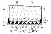
- FIG. 2 is a plan view schematically showing the light guide plate and the LED array according to the first embodiment.
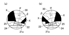
- 3 is an enlarged plan view showing the area A and the area B in FIG.
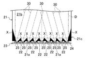
- FIG. 4 is a plan view schematically showing the light guide plate and the LED array according to the second embodiment.
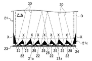
- FIG. 5 is a plan view schematically showing a light guide plate and an LED array according to the third embodiment.
- FIG. 6 is a plan view schematically showing a light guide plate and an LED array according to the fourth embodiment.
- FIG. 7 is a plan view schematically showing a light guide plate and an LED array according to the fifth embodiment.
- FIG. 8 is a plan view schematically showing a light guide plate and an LED array according to another embodiment.
- FIG. 1 is an exploded perspective view schematically showing a schematic configuration of the liquid crystal display device S.
- the shape of the light guide plate 21 is simplified, and the number of LEDs 25 is not strictly shown.
- the liquid crystal display device S includes a liquid crystal display panel 10 and a backlight unit 20 as an illumination device disposed on the back side of the liquid crystal display panel 10.
- the viewer side (upper side in FIG. 1) of the liquid crystal display device S is referred to as a front side
- the opposite side is referred to as a back side.
- the liquid crystal display panel 10 is a known transmissive or transmissive / reflective liquid crystal display panel, and is configured to display an image by modulating light from the backlight unit 20.
- the liquid crystal display panel 10 is formed in, for example, a rectangular shape, and although not shown, an active matrix substrate, a counter substrate disposed to face the active matrix substrate, the active matrix substrate and the counter substrate, And a liquid crystal layer sealed with a frame-shaped sealing material.
- the liquid crystal display panel 10 has, for example, a rectangular display area D that displays an image in an inner region of the sealing material, that is, a region where the liquid crystal layer is provided, and a non-display of a rectangular frame shape on the outer periphery of the display area D. It has a frame area F that is an area.
- the display area D is configured by arranging a plurality of pixels, which are the minimum unit of image display, in a matrix.
- a plurality of gate wirings and source wirings are formed orthogonal to each other via a gate insulating film so as to partition each pixel.
- a TFT Thin Film Transistor
- Each pixel is provided with a pixel electrode connected to the TFT.
- the counter substrate is provided with a black matrix in a lattice shape so as to correspond to the gate wiring and the source wiring. Between the black matrix lattices, red, green and blue color filters are provided so as to be arranged periodically.
- a common electrode is provided on the black matrix and each color filter so as to cover them, and columnar photo spacers are formed on the common electrode.
- the active matrix substrate and the counter substrate are each provided with an alignment film on the inner surface facing each other and a polarizing plate on the outer surface.
- the liquid crystal layer is made of, for example, a nematic liquid crystal material having electro-optical characteristics.
- the liquid crystal display panel 10 is fitted on a metal bezel 14 which is located on the front side and covers the frame area F.
- the bezel 14 is formed by pressing a metal plate into a rectangular frame shape, and has a window 14 a that exposes the display area D of the liquid crystal display panel 10. Further, the bezel 14 is fixed by screwing or the like to the outer peripheral portion of a frame body 28 of the backlight unit 20 described later.
- the outer peripheral edge of the liquid crystal display panel 10 is fixed to the backlight unit 20 via the rim sheet 12.
- the rim sheet 12 is, for example, a double-sided pressure-sensitive adhesive tape having a light shielding property, and prevents light from the backlight unit 20 from coming out from the peripheral edge of the liquid crystal display panel 10 to the front side.
- the backlight unit 20 includes an LED array 23 that is a light source unit, a light guide plate 21 that guides light from the LED array 23 to the liquid crystal display panel 10 side, and a plurality of optical elements stacked on the front side of the light guide plate 21.
- the array 23 is of an edge light type arranged on the side of the light guide plate 21.
- the plurality of optical sheets 27 are, for example, a diffusion sheet 27a, a lower lens sheet 27b, and an upper lens sheet 27c.
- the diffusion sheet 27a has a function of diffusing transmitted light to prevent display unevenness and the like.
- the diffusion sheet 27a has, for example, a film made of a transparent resin such as polyethylene terephthalate (PET) having a rough surface, or a film made of a similar transparent resin as a base material, and acrylic beads and the like are held on the surface thereof with a binder. It has a configuration.
- the lower lens sheet 27b and the upper lens sheet 27c have a function of improving the brightness by condensing the transmitted light in the directly upward direction.
- Each of the lens sheets 27b and 27c is formed so that, for example, a plurality of prisms extending in parallel with each other are formed on a film made of transparent resin, and the prisms are orthogonal to each other.
- the optical sheet includes the diffusion sheet 27a, the lower lens sheet 27b, and the upper lens sheet 27c.
- the present invention is not limited to this.
- a second diffusion sheet is further provided on the upper lens sheet 27c. May be laminated, and various optical sheets can be appropriately combined according to the price and performance of the liquid crystal display device S.
- the frame body 28 forms a rectangular frame-shaped casing having both the front side and the back side opened, and has an opening 28a for exposing the reflection sheet 29 on the back side. Further, the frame body 28 has a support portion 28 b that protrudes in a step shape and supports the light guide plate 21, and a light source housing portion (not shown) that houses the LED array 23 inside the frame body 28.
- the reflection sheet 29 has a function of reflecting light incident from the front side, and reflects light leaking to the back side of the light guide plate 21 toward the light guide plate 21 side.
- the reflection sheet 29 is made of, for example, a metal thin film such as silver (Ag) or a white polyester film.
- FIG. 2 shows the configuration of the light guide plate 21 and the LED array 23 according to the present embodiment.
- the display area D of the liquid crystal display panel 10 is illustrated for the sake of convenience so that the characteristic configuration of the present invention can be easily understood.
- FIG. 3A shows an enlarged plan view of the area A in FIG. 2
- FIG. 3B shows an enlarged plan view of the area B in FIG.
- the light guide plate 21 is formed, for example, in a substantially rectangular shape, and as shown in FIG. 2, a light incident surface 21a on which light from the LED array 23 is incident and a light emitting surface that emits light incident from the light incident surface 21a 21b.
- the light emitting surface 21b constitutes a front surface, and the light incident surface 21a is located on the side of one side of the light emitting surface 21b.
- a predetermined dot pattern (not shown) is formed on the back surface of the light guide plate 21 to reflect the light incident on the front surface to the front surface.
- the light guide plate 21 is configured to guide light incident on the inside from the light incident surface 21a to the light exit surface 21b side while diffusing.
- the light guide plate 21 is made of a transparent resin such as polycarbonate or polymethyl methacrylate, and can be formed by, for example, injection molding, extrusion molding, hot press molding, cutting molding, or the like. However, it is not limited to these formation methods, What is necessary is just the formation method in which the same characteristic is exhibited.
- a plurality of protrusions 22 are formed on the light incident portion 21c, which is a portion where light from the LED array 23 is incident on the light guide plate 21, so that the light incident surface 21a is perpendicular to the light emission axis 30 of each LED 25 described later. Is formed.
- Each of the protrusions 22 is formed as a protrusion having a triangular cross section extending in the vertical direction (thickness direction) of the light guide plate 21. Thereby, the light incident surface 21a is formed in a wedge shape as a whole.
- the LED array 23 includes a flexible printed circuit board (Flexible Printed Circuit, hereinafter referred to as FPC) 24 and a plurality of LEDs 25 which are point light sources mounted on the FPC 24.
- FPC Flexible Printed Circuit
- LEDs 25 which are point light sources mounted on the FPC 24.
- the FPC 24 is fixed to the inner surface of the frame body 28 by adhering to the inner surface of the frame body 28 using, for example, double-sided tape.
- the FPC 24 and the frame body 28 have a positioning structure for suitably positioning the FPC 24.
- This positioning structure includes, for example, a projection (not shown) provided on the frame 28 and an opening (not shown) provided on the FPC 24 so as to be fitted to the projection.
- the plurality of LEDs 25 are linearly arranged at predetermined intervals along the light incident surface 21 a of the light guide plate 21. Each LED 25 is mounted on the FPC 24 using solder so that its light emitting surface faces the light incident surface 21a side. Each LED 25 is configured to emit light radially. For example, a white LED is employed for each of these LEDs 25.
- the LED array 23 of the present embodiment has a configuration in which the LED 25 is not disposed at the center position of the light incident surface 21a of the light guide plate 21.
- the same number of LEDs 25 are equally divided on both sides of the light incident surface 21a of the light guide plate 21 as a boundary, and all these LEDs 25 have a light emission axis 30 that emits the light.
- the light beam emitted along the axis 30 is provided so as to be inclined with respect to a direction orthogonal to the arrangement direction of the LEDs 25 and parallel to the light emission surface 21b, that is, the front direction, so as to approach the center side of the light guide plate 21. ing. This shortens the length of the dark portion X (blacked portion in FIG.
- each LED 25 is provided in a state where the light emission axis 30 is inclined toward the center of the light guide plate 21, so that the extending direction of the dark portion X generated between the adjacent LEDs 25 is the light emission. Since it inclines corresponding to the inclination of the shaft 30, the length extending in the front direction of the dark part X generated between the adjacent LEDs 25 as compared with the case where the radiation axis 30 of the light emitted from each LED 25 is oriented in the front direction. The length can be shortened. Accordingly, the length of the dark part X extending between the adjacent LEDs 25 extending to the display area D side can be shortened without increasing the number of LEDs 25, and the dark part X extends to the display area D. Can be prevented.
- each LED 25 is in a state in which the direction of the radiation axis 30 of the light is adjusted symmetrically with respect to the central position of the light incident surface 21 a of the light guide plate 21, and thus is taken into the light guide plate 21 from each LED 25. It is possible to prevent the light amount from being biased in the left and right regions with reference to the center position of the light incident surface 21a. As a result, it is possible to take out planar light with excellent uniformity with little deviation in the amount of light from the light exit surface 21 b of the light guide plate 21.
- the pitch P2 of the LEDs 25 adjacent to each other at positions close to the left and right of the central position of the light incident surface 21a of the light guide plate 21 is larger than the pitch P1 of the LEDs 25 adjacent on both ends in the arrangement direction of the LEDs 25. .
- the plurality of LEDs 25 are arranged in this way, the light emission axes 30 of the adjacent LEDs 25 are inclined in directions intersecting each other at positions close to the left and right of the central position of the light incident surface 21a of the light guide plate 21.
- the length extending in the front direction of the dark part X generated between these adjacent LEDs 25 can be shortened. Thereby, the number of LED25 required as the backlight unit 20 can be reduced.
- the inclination angle ⁇ of the light emission axis 30 in each LED 25 is an angle equal to or less than half of the emission angle ⁇ of light emitted from the LED 25, as shown in FIGS. 3 (a) and 3 (b).
- the emission angle ⁇ of light emitted from the LED 25 is about 10 ° to 60 ° (for example, 30 °)
- the inclination angle ⁇ of the light emission axis 30 in each LED 25 is relative to the front direction. It is about 5 ° to 30 ° (for example, 15 °).
- the light beam emitted along the outermost position on the anti-tilt side of the light emitted from each LED 25 propagates in the front direction. Or propagates in the direction toward the lateral outer side of the light guide plate 21 with respect to each LED 25. Thereby, light can be satisfactorily taken into the portions of the light guide plate 21 corresponding to both side portions of the light incident surface 21a.
- the inclination angle ⁇ of the light emission axis 30 of each LED 25 is the same angle. That is, the light emission axes 30 of the LEDs 25 are parallel to each other.
- the light emitted from the adjacent LEDs 25 having the light emission axis 30 in such an inclined state is lighter than the light emitted from the adjacent LEDs 25 at the same pitch with the light emission axes 30 directed in the front direction. Since it intersects early on the incident surface 21a side, the length extending in the front direction of the dark part X generated between the adjacent LEDs 25 can be surely shortened.
- the LED array 23 is accommodated in the light source accommodating portion inside the frame body 28 in a state where each LED 25 is brought into contact with the light incident surface 21a at the projection 22 formation portion of the light guide plate 21.
- the light incident surface 21a of the light guide plate 21 and the light emission axis 30 of the inclined light of each LED 25 are perpendicular to each other because the projection 22 is formed on the light incident portion 21c of the light guide plate 21. There is no.
- scattering of the light emitted from each LED 25 on the light incident surface 21a can be suppressed, so that the light can be efficiently taken into the light guide plate 21, and as a result, the light output surface 21b of the light guide plate 21. It is possible to prevent the luminance of the planar light emitted from the light from decreasing.
- the length of the dark portion X generated between the adjacent LEDs 25 extending to the display area D side can be shortened to prevent the dark portion X from reaching the display area D, and the light guide plate It is possible to extract planar light having excellent uniformity with little deviation in light amount from the light emitting surface 21b of 21.
- the number of LEDs 25 required as the backlight unit 20 can be reduced. Thereby, it is possible to improve the display quality by eliminating the luminance unevenness in the display area D while reducing the cost.
- the liquid crystal display device S is adapted to the frame area F of the liquid crystal display panel 10. Narrowing of the frame can also be realized.
- FIG. 4 is a plan view showing configurations of the light guide plate 21 and the LED array 23 according to the second embodiment.
- the light guide plate 21 or the LED array 23 is configured in the same manner as the liquid crystal display device S except for the configuration of the first embodiment, so that the light guide plate has a different configuration. Only the LED 21 and the LED array 23 will be described, and the same components are left to the description of the first embodiment based on FIGS. 1 to 3, and the detailed description thereof is omitted.
- the LED array 23 is configured such that the LED 25 is not disposed at the center position of the light incident surface 21a of the light guide plate 21, but the LED array 23 of the present embodiment is configured as shown in FIG.
- the LED 25 is arranged at the center position of the light incident surface 21a.
- the LED 25 arranged at the center of the light incident surface 21a is provided with the light emission axis 30 facing the front.
- Embodiment 2- when only the LED 25 having the light emission axis 30 inclined as in the first embodiment is arranged along the light incident surface 21a, the light emission angle ⁇ of each LED 25 and the light guide plate 21 When the arrangement balance of the LEDs 25 is unbalanced in relation to the length of the light incident surface 21a, the arrangement balance can be adjusted favorably.
- the length of the dark portion X generated between the adjacent LEDs 25 extending toward the display area D is shortened so that the dark portion X is displayed in the display area.
- planar light having excellent uniformity with little deviation in the amount of light can be extracted from the light exit surface 21 b of the light guide plate 21.
- FIG. 5 is a plan view showing configurations of the light guide plate 21 and the LED array 23 according to the third embodiment.
- all the LEDs 25 located on both sides of the light incident surface 21a of the light guide plate 21 are provided with the light emission axis 30 inclined with respect to the front direction.
- the LED array 23 of the present embodiment excludes the LEDs 25 positioned at both ends in the arrangement direction of the LEDs 25 in each LED 25 positioned on both sides of the light incident surface 21 a as a boundary.
- the light emission axis 30 is inclined with respect to the front direction.
- the LEDs 25 located at both ends of the LED array 23 are provided with the light emission axis 30 facing the front.
- Embodiment 3- light can be sufficiently taken into the portions of the light guide plate 21 corresponding to both side portions of the light incident surface 21 a, and the surface shape is more uniform from the light emitting surface 21 b of the light guide plate 21. Light can be extracted. And thereby, the brightness nonuniformity between the center side in the display area D of the liquid crystal display device S and a peripheral part can be eliminated as much as possible. About the other, the effect similar to the said Embodiment 1 can be acquired.
- FIG. 6 is a plan view showing configurations of the light guide plate 21 and the LED array 23 according to the fourth embodiment.
- the inclination angle ⁇ of the light emission axis 30 in each LED 25 is the same angle.
- the inclination angle ⁇ of 30 gradually decreases in the range of, for example, 5 ° to 30 ° from both ends in the arrangement direction of the LEDs 25 toward the center.
- Embodiment 4- light can be satisfactorily taken into the portions of the light guide plate 21 corresponding to both sides of the light incident surface 21a, and the surface shape is more uniform from the light emitting surface 21b of the light guide plate 21. Light can be extracted. Thereby, luminance unevenness between the center side and the peripheral portion in the display area D of the liquid crystal display device S can be eliminated. About the other, the effect similar to the said Embodiment 1 can be acquired.
- FIG. 7 is a plan view showing configurations of the light guide plate 21 and the LED array 23 according to the fifth embodiment.
- the inclination angle ⁇ of the light emission axis 30 in each LED 25 is gradually decreased from the both end sides in the arrangement direction of the LED 25 toward the center side.
- the LED 25 having a relatively large inclination angle ⁇ of the light emission axis 30 (for example, 15 °) and the angle 25 having a relatively small inclination angle ⁇ of the light emission axis 30 (for example, 10 °). °) LEDs 25 are alternately arranged.
- Embodiment 5- the same effect as that of the first embodiment can be obtained, and the display quality can be improved by eliminating the luminance unevenness in the display area D while reducing the cost.
- the narrow frame of the liquid crystal display device S can be realized in accordance with the frame area F of the liquid crystal display panel 10.
- FIG. 8 is a plan view showing configurations of the light guide plate 21 and the LED array 23 according to another embodiment.
- the projection 22 is formed on the light incident portion 21c of the light guide plate 21 and the light incident surface 21a is formed in a wedge shape.
- the present invention is not limited to this, and the light guide plate 21 is not limited thereto.
- the light incident surface 21a may be formed in a planar shape as shown in FIG. In this case, since the amount of light incident on the light guide plate 21 is reduced according to the distance between each LED 25 and the light incident surface 21a of the light guide plate 21, each LED 25 has the light emission axis 30 in the front direction. It is preferable to be inclined at a shallow angle of about 5 °.
- the inclination angle ⁇ of the light emission axis 30 of each LED 25 is gradually decreased from both ends in the arrangement direction of the LED 25 toward the center, but the present invention is not limited thereto.
- the inclination angle ⁇ of the light emission axis 30 in each LED 25 may gradually increase from both ends of the LED in the arrangement direction toward the center side. Compared with the case where it is arranged in the front direction, the length of the dark portion X generated between the adjacent LEDs 25 extending toward the display area D may be smaller.
- the inclination angle ⁇ of the light emission axis 30 of the inclined light of each LED 25 is the same angle in the adjacent LEDs 25, or the LED 25 located on the outer side in the arrangement direction of the LED 25 is more than the LED 25 located on the inner side in the same direction. It is preferable that the angle is larger.
- the inclination angle ⁇ of the radiation axis 30 in each LED 25 is set, the light emitted from each adjacent LED 25 intersects on the light incident surface 28a side at an early stage, as in the first embodiment.
- the length extending in the front direction of the dark part X generated between the adjacent LEDs 25 can be surely shortened.
- each LED 25 is mounted on the FPC 24, but the mounting of the LED 25 is not limited to the FPC 24, and may be mounted on a hard substrate.
- the active matrix driving type liquid crystal display device is described as an example of the liquid crystal display device S.
- the present invention is not limited to this, and the passive matrix driving type liquid crystal display device is of course also used. Can be applied.
- the present invention is useful for an illumination device and a liquid crystal display device including the same, and in particular, a display area in a dark part generated between adjacent point light sources without increasing the number of point light sources. It is suitable for an illuminating device and a liquid crystal display device including the illuminating device that are desired to shorten the length extending to the side and prevent the dark part from reaching the display area.
- liquid crystal display device 10 liquid crystal display panel 20 backlight unit (illumination device) 21 Light guide plate 21a Light incident surface 21b Light output surface 22 Projection 25 LED (point light source) 30 Radiation axis of light
Landscapes
- Physics & Mathematics (AREA)
- Nonlinear Science (AREA)
- Mathematical Physics (AREA)
- Chemical & Material Sciences (AREA)
- Crystallography & Structural Chemistry (AREA)
- General Physics & Mathematics (AREA)
- Optics & Photonics (AREA)
- Planar Illumination Modules (AREA)
Abstract
導光板(21)と、該導光板(21)の光入射面(21a)に沿って所定の間隔をあけて配列されて光を放射状に出射する複数のLED(25)とを備えたバックライトユニット(20)において、光入射面(21a)の中央位置を境にその両側に位置する各LED(25)の光の放射軸(30)を、該放射軸(30)に沿って出射された光線が導光板(21)の中央側に接近するように当該LED(25)の配列方向と直交し且つ光出射面(21b)と平行な方向に対して傾斜させる。
Description
本発明は、照明装置及びそれを備えた液晶表示装置に関し、特に、表示エリアの光源側縁部における輝度ムラ防止対策に関するものである。
従来から、液晶表示装置として、液晶表示パネルの背面側に照明装置としてのバックライトユニットを備え、該バックライトユニットからの光を液晶表示パネルによって変調することで透過表示を行う透過型の液晶表示装置が知られている。また、バックライトユニットからの光だけでなく、周囲の環境光をも利用して表示を行う透過反射両用型(半透過型とも呼ばれる)の液晶表示装置も知られている。
これら透過型及び透過反射両用型の液晶表示装置に用いられるバックライトユニットには、表示装置の薄型化を実現するために、いわゆるエッジライト方式が好適に採用される。このエッジライト方式のバックライトユニットは、導光板と、該導光板の側方に設けられた光源とを有し、該光源からの光を導光板により均斉化して液晶表示パネル側に面状光として出射するように構成されている。
上記光源としては、従来、冷陰極管が用いられることが多かったが、近年では、発光ダイオード(Light Emitting Diode、以下、LEDと称する)を所定の間隔で線状に複数配列したLEDアレイを用いることが多くなっている。これは、LEDが、冷陰極管と比較して、低消費電力性に優れ、薄型化が可能であるという利点を有するからである。
LEDアレイの各LEDは、通常、出射する光の放射軸を、LEDの配列方向に直交し且つ導光板の光出射面に平行な方向(以下、正面方向ともいう)に向けて設けられている。なお、本明細書でいう「光の放射軸」とは、光源からの配光(光束)分布の中心軸を意味し、光源から等距離の位置において単位面積当たりの光束量がおよそ最大となるような性質を有する光源から出射される光の基軸である。
また、LEDアレイを光源として備えたバックライトユニットとして、特許文献1には、導光板の一辺に沿って配列された複数のLEDのうち両端側に位置する各LEDを、光の出射方向がLED配列方向と直交する方向に対して斜めになるように配置することにより、LEDアレイによる光の照射領域を拡大させたバックライトユニットが開示されている。
上記LEDアレイを光源として備えたエッジライト方式のバックライトユニットでは、個々のLEDは点状光源であるため、光が所定の角度で放射状に広がるように出射されるが、隣り合うLED間でこれら各LEDから出射された光が交わるまでの領域に暗部が発生することが避けられない。この暗部が液晶表示パネルの表示エリアにまで及ぶと、画像表示を行う際に表示エリアにおけるLEDアレイ側の縁部に沿って輝度ムラが視認され、表示品位が低下してしまう。
上記LED間の暗部が表示エリアに及ぶことを防止するには、LEDの光が入射する導光板の入光部と表示エリアとの距離を長くして、表示エリア外側に上記暗部を完全に隠すようにする構造を採用することが考えられるが、導光板の入光部と表示エリアとの間の部分は液晶表示装置の非表示エリアである額縁エリアを構成する部分であるので、同構造では、額縁エリアが拡大することになり、狭額縁化の妨げとなる。
さりとて、上記LED間の暗部の表示エリア側へ延びる長さを短くして導光板の入光部と表示エリアとの距離を短くすべく、隣り合うLED間のピッチを狭く設計すると、LEDアレイを構成するのに必要なLEDの個数が増えてしまい、バックライトユニットがコストアップになる。
本発明は、斯かる点に鑑みてなされたものであり、その目的とするところは、点状光源の個数を増やすことなく隣り合う点状光源の間に発生する暗部の表示エリア側へ延びる長さを短くして、当該暗部が表示エリアにまで及ぶことを防止することにある。
上記の目的を達成するために、この発明では、各点状光源から出射される光の放射軸の向きを工夫した。
具体的には、本発明は、点状光源のアレイを光源として備えた照明装置及びそれを備えた液晶表示装置を対象とし、以下の解決手段を講じたものである。
すなわち、第1の発明は、照明装置であって、光出射面の側部に光入射面を有し、該光入射面から内部に入射した光を導光して上記光出射面から出射する導光板と、上記光入射面に沿って所定の間隔をあけて配列され、該光入射面に向かって光を放射状に出射する複数の点状光源とを備え、上記光入射面の中央位置を境にその両側に位置する各点状光源は、当該点状光源の配列方向の両端に位置する点状光源を除いて、又はその全てが、光の放射軸を、該放射軸に沿って出射された光線が上記導光板の中央側に接近するように当該点状光源の配列方向と直交し且つ上記光出射面と平行な方向、つまり正面方向に対して傾斜させて設けられていることを特徴とする。
この第1の発明では、導光板の光入射面の中央位置を境にその両側に位置する各点状光源うち点状光源の配列方向の両端に位置する点状光源を除いた少なくとも残りの点状光源から出射される光の放射軸が、該放射軸に沿って出射された光線が上記導光板の中央側に接近するように正面方向に対して傾斜している。このように光の放射軸を導光板の中央側に傾斜させた状態に点状光源を配列しても、隣り合う点状光源の間に暗部が発生することは避けられないが、該暗部の延びる方向が光の放射軸の傾斜に対応して傾くので、各点状光源から出射される光の放射軸が正面方向に向いている場合に比べて、隣り合う点状光源の間に発生する暗部の正面方向へ延びる長さを短くすることが可能になる。これにより、点状光源の個数を増やさなくても、表示パネルと組み合わせた状態において、隣り合う点状光源の間に発生する暗部の表示エリア側へ延びる長さを短くすることができ、当該暗部が表示エリアにまで及ぶことを防止することが可能になる。
さらに、第1の発明では、各点状光源が導光板の光入射面の中央位置を境にして線対称にその光の放射軸の向きを調整した状態にあるので、各点状光源から導光板の内部に取り込まれる光量が光入射面の中央位置を基準に左右の領域で偏ることが防止される。これによって、導光板の光出射面から光量の偏りが少ない均一性の高い面状光を取り出すことが可能になる。
また、導光板の光入射面の中央位置に点状光源を設けない場合、導光板の光入射面の中央位置の左右に近接した位置で隣り合う点状光源は、それぞれの光の放射軸が互いに交差する方向に傾斜しているので、点状光源の配列方向の両端側で隣り合う点状光源よりもピッチ間隔を大きくあけても、これら隣り合う点状光源の間に発生する暗部の正面方向へ延びる長さを短くすることができる。これにより、照明装置として必要な点状光源の個数を減らしてコストダウンを図ることが可能である。
第2の発明は、第1の発明の照明装置において、上記複数の点状光源は、上記光入射面の中央位置に配置された点状光源を含み、上記光入射面の中央位置に配置された点状光源は、光の放射軸を、当該点状光源の配列方向と直交し且つ上記光出射面と平行な方向、つまり正面方向に向けて設けられていることを特徴とする。
この第2の発明では、導光板の光入射面の中央位置に光の放射軸を正面方向に向けた点状光源が配置されている。このように光入射面の中央位置に点状光源を配置することにより、光の放射軸を傾斜させた点状光源のみを光入射面に沿って配置させると各点状光源の光の放射角度と光入射面の長さとの関係で点状光源の配置バランスがアンバランスになる場合に、その配置バランスを良好に調整することが可能になる。
第3の発明は、第1又は第2の発明の照明装置において、上記点状光源の傾斜させた光の放射軸の傾斜角度は、隣り合う点状光源において、同一角度であるか、若しくは当該点状光源の配列方向外側に位置する点状光源が同方向内側に位置する点状光源よりも大きい角度であることを特徴とする。
この第3の発明では、隣り合う点状光源の光の放射軸が、互いに平行な状態にあるか、若しくは導光板の中央側に向かって接近する状態にある。このような傾斜状態にある光の放射軸を有する隣り合う各点状光源から出射された光は、光の放射軸をそれぞれ正面方向を向けて同ピッチで隣り合う各点状光源から出射された光よりも光入射面側で早期に交差するので、隣り合う点状光源の間に発生する暗部の正面方向へ延びる長さを確実に短くすることが可能になる。
第4の発明は、第1~第3の発明のいずれか1つに記載の照明装置において、上記点状光源の傾斜させた光の放射軸の傾斜角度は、当該点状光源から出射される光の放射角度の半分以下の角度であることを特徴とする。
この第4の発明では、各点状光源における光の放射軸の傾斜角度が、当該各点状光源から出射される光の反傾斜側の最外位置に沿って出射された光線が正面方向に伝播するか若しくは導光板の側方外側に向かう方向に伝播するように設定されている。このように各点状光源における光の放射軸の傾斜角度が設定されていれば、導光板における光入射面の両側部に対応する部分にも良好に光を取り込むことができ、導光板の光出射面から均一性に優れた面状光を取り出すことが可能になる。
第5の発明は、第1~第4の発明のいずれか1つの照明装置において、上記各点状光源からの光が入射する導光板部分である入光部には、上記光入射面が上記点状光源の傾斜させた光の放射軸と直角をなすように突起が形成されていることを特徴とする。
第5の発明では、導光板の入光部に突起が形成されていることによって、該導光板の光入射面と点状光源の傾斜させた光の放射軸とが直角をなしている。これにより、点状光源から出射された光の光入射面での散乱が抑えられるので、該導光板の内部に効率良く光が取り込まれて、導光板の光出射面から出射される面状光の輝度低下が防止される。
第6の発明は、第1~第5の発明のいずれか1つの照明装置において、上記各点状光源は、LEDであることを特徴とする。
この第6の発明では、各点状光源にLEDを採用している。LEDは、冷陰極管と比較して、低消費電力性に優れ、薄型化が可能であるという利点を有する。したがって、照明装置について、ひいては当該照明装置を備える液晶表示装置について低消費電力化及び薄型化を実現することができる。
第7の発明は、液晶表示装置であって、第1~第6の発明のいずれか1つの照明装置と、該照明装置が備える導光板の光出射面前方に配置された液晶表示パネルとを備えることを特徴とする。
この第7の発明では、第1~第6の発明のいずれか1つの照明装置を備える。第1~第6の発明の照明装置は、点状光源の個数を増やすことなく隣り合う点状光源の間に発生する暗部の表示エリア側へ延びる長さを短くして、当該暗部が表示エリアにまで及ぶことを防止できる上に、導光板の光出射面から光量の偏りが少ない均一性の高い面状光を取り出すことができるという優れた特性を有する。したがって、第7の発明の液晶表示装置によると、コストアップを招くことなく表示エリアに輝度ムラが視認されることを解消して表示品位を向上させることができ、しかも狭額縁化にも寄与する構造を実現することが可能である。
本発明によれば、導光板の光入射面の中央位置を境にその両側に位置する各点状光源は、当該点状光源の配列方向の両端に位置する点状光源を除いて、又はその全てが、光の放射軸を、該放射軸に沿って出射された光線が上記導光板の中央側に接近するように正面方向に対して傾斜させて設けられているので、点状光源の個数を増やすことなく隣り合う点状光源の間に発生する暗部の表示エリア側へ延びる長さを短くして、当該暗部が表示エリアにまで及ぶことを防止できる上に、導光板の光出射面から光量の偏りが少ない均一な面状光を取り出すことができる。
以下、本発明の実施形態を図面に基づいて詳細に説明する。なお、本発明は、以下の各実施形態に限定されるものではない。
《発明の実施形態1》
この実施形態1では、本発明に係る液晶表示装置の一例として、アクティブマトリクス駆動方式の液晶表示装置Sについて説明する。この液晶表示装置Sの概略構成を模式的に示す分解斜視図を図1に示す。この図1では、便宜上、導光板21の形状については簡略化し、LED25についてはその個数まで厳密に示していない。
この実施形態1では、本発明に係る液晶表示装置の一例として、アクティブマトリクス駆動方式の液晶表示装置Sについて説明する。この液晶表示装置Sの概略構成を模式的に示す分解斜視図を図1に示す。この図1では、便宜上、導光板21の形状については簡略化し、LED25についてはその個数まで厳密に示していない。
液晶表示装置Sは、図1に示すように、液晶表示パネル10と、該液晶表示パネル10の背面側に配置された照明装置としてのバックライトユニット20とを備えている。なお、本明細書において、液晶表示装置Sの観察者側(図1で上側)を前面側と称し、それとは反対側(図1で下側)を背面側と称する。
液晶表示パネル10は、公知の透過型又は透過反射両用型の液晶表示パネルであり、バックライトユニット20からの光を変調することによって画像表示を行うように構成されている。典型的には、液晶表示パネル10は、例えば矩形状に形成され、図示しないが、アクティブマトリクス基板と、該アクティブマトリクス基板に対向して配置された対向基板と、これらアクティブマトリクス基板と対向基板との間に枠状のシール材によって封入された液晶層とを備えている。
そして、液晶表示パネル10は、シール材の内側領域、つまり液晶層が設けられた領域に画像表示を行う例えば矩形状の表示エリアDを、該表示エリアDの外周に例えば矩形枠状の非表示エリアである額縁エリアFを有している。表示エリアDは、画像表示の最小単位である画素がマトリクス状に複数配列して構成されている。
アクティブマトリクス基板には、各画素を区画するようにゲート配線とソース配線とがゲート絶縁膜を介し互いに直交してそれぞれ複数本形成されている。これらゲート配線とソース配線との各交差部分には、TFT(Thin Film Transistor)が設けられている。そして、各画素には、上記TFTに接続された画素電極が設けられている。
対向基板には、上記ゲート配線及びソース配線に対応するようにブラックマトリクスが格子状に設けられている。このブラックマトリクスの格子間には、赤色層、緑色層及び青色層のカラーフィルタが周期的に配列するように設けられている。そして、上記ブラックマトリクス及び各カラーフィルタ上にはこれらを覆うように共通電極が設けられ、該共通電極上には柱状のフォトスペーサが形成されている。
これらアクティブマトリクス基板及び対向基板は、互いに対向する内側表面に配向膜がそれぞれ設けられていると共に、外側表面に偏光板が設けられている。また、液晶層は、例えば電気光学特性を有するネマチックの液晶材料などにより構成されている。
上記液晶表示パネル10は、その前面側に位置して額縁エリアFを覆う金属製のベゼル14に嵌め込まれている。このベゼル14は、金属板を矩形枠状にプレス加工することで形成されており、液晶表示パネル10の表示エリアDを露出させる窓14aを有する。また、ベゼル14は、後述するバックライトユニット20の枠体28の外周部にネジ止め等することによって固定される。
そして、液晶表示パネル10は、その外周縁部がリムシート12を介してバックライトユニット20に固定されている。リムシート12は、例えば遮光性を有する両面粘着テープであり、バックライトユニット20からの光が液晶表示パネル10の周縁部から前面側に抜けないようにしている。
バックライトユニット20は、光源部であるLEDアレイ23と、LEDアレイ23からの光を液晶表示パネル10側に導光する導光板21と、該導光板21の前面側に積層された複数の光学シート27と、これらLEDアレイ23、導光板21及び各光学シート27を保持する枠体28と、該枠体28の下部で導光板21の背面側に配置された反射シート29とを備え、LEDアレイ23が導光板21の側部に配置されたエッジライト方式のものである。
複数の光学シート27は、例えば、拡散シート27a、下側レンズシート27b及び上側レンズシート27cである。
拡散シート27aは、表示ムラ等を防止すべく透過光を拡散させる機能を有している。この拡散シート27aは、例えば、表面状態の粗いポリエチレンテレフタレート(PET)などの透明樹脂からなるフィルムや、これと同様な透明樹脂からなるフィルムを基材としてその表面にアクリルビーズなどをバインダーで保持した構成を有する。
下側レンズシート27b及び上側レンズシート27cは、透過光を直上方向に集光して輝度を向上させる機能を有している。これら各レンズシート27b,27cは、例えば、それぞれ透明樹脂からなるフィルム上に互いに平行に延びる複数のプリズムが形成されており、互いのプリズムが直交するように配置されている。
なお、本実施形態では、光学シートとして、拡散シート27a、下側レンズシート27b及び上側レンズシート27cを備えるとしているが、これに限らず、例えば上側レンズシート27c上にさらに2枚目の拡散シートが積層されていてもよく、各種光学シートを液晶表示装置Sの価格や性能に応じて適宜組み合わせることが可能である。
枠体28は、前面側及び背面側が共に開口された矩形枠状のケーシングを構成しており、背面側に反射シート29を露出させる開口28aを有している。また、この枠体28は、枠体28内側に、段状に張り出して導光板21を支持する支持部28bと、LEDアレイ23を収容する光源収容部(不図示)とを有している。
反射シート29は、前面側から入射した光を反射する機能を有し、導光板21の背面側に漏れた光を導光板21側へ反射するようになっている。この反射シート29は、例えば、銀(Ag)などの金属薄膜フィルムや白色ポリエステルフィルムなどからなる。
本実施形態に係る導光板21及びLEDアレイ23の構成を図2に示す。この図2では、本発明の特徴的構成を理解しやすいように、便宜上、液晶表示パネル10の表示エリアDを図示している。また、図2中の領域Aの拡大平面図を図3(a)に、図2中の領域Bの拡大平面図を図3(b)にそれぞれ示す。
導光板21は、例えば略矩形状に形成され、図2に示すように、LEDアレイ23からの光が入射する光入射面21aと、該光入射面21aから入射した光を出射する光出射面21bとを有している。光出射面21bは前面側表面を構成し、光入射面21aは光出射面21bの一辺側の側部に位置している。
導光板21の背面部には、内部に入射した光を前面側に反射させるための所定のドットパターン(不図示)が形成されている。そして、導光板21は、光入射面21aから内部に入射した光を拡散しながら光出射面21b側に導光するように構成されている。
上記導光板21は、ポリカーボネートやポリメチルメタクリレートなどの透明樹脂からなり、例えば射出成型や押出成型、熱プレス成型、切削成型などによって形成することが可能である。ただし、これらの形成方法には限定されず、同様の特性が発揮される形成方法であればよい。
この導光板21においてLEDアレイ23からの光が入射する部分である入光部21cには、光入射面21aが後述する各LED25の光の放射軸30と直角をなすように複数の突起22が形成されている。これら各突起22は、導光板21の上下方向(厚さ方向)に延びる縦断面三角形状の突条に形成されている。これにより、光入射面21aは全体として楔状に形成されている。
LEDアレイ23は、フレキシブルプリント配線基板(Flexible Printed Circuit、以下、FPCと称する)24と、該FPC24に実装された点状光源である複数のLED25とを備えている。これにより、液晶表示装置Sについて、冷陰極管を光源として用いる場合と比較して、低消費電力化及び薄型化が実現されている。
FPC24は、上記枠体28の光源収容部にてその内面に例えば両面テープなどにより接着して固定されている。FPC24及び枠体28は、FPC24の位置決めを好適に行うために位置決め構造を有している。この位置決め構造は、例えば、枠体28に設けられた突起(不図示)と、該突起に嵌合するようにFPC24に設けられた開口部(不図示)とで構成されている。
複数のLED25は、導光板21の光入射面21aに沿って所定の間隔をあけて直線状に配列されている。各LED25は、FPC24上に半田を用いてその発光面が光入射面21a側を向くように実装されている。各LED25は、光を放射状に出射するように構成されている。これら各LED25には、例えば白色LEDが採用される。
本実施形態のLEDアレイ23は、導光板21の光入射面21aの中央位置にLED25が配置しない構成となっている。そして、導光板21の光入射面21aの中央位置を境にその両側には同じ個数のLED25が2等分して配置されており、これら全てのLED25は、光の放射軸30を、該放射軸30に沿って出射された光線が導光板21の中央側に接近するように当該LED25の配列方向と直交し且つ光出射面21bと平行な方向、つまり正面方向に対して傾斜させて設けられている。これにより、LED25の個数を増やすことなく隣り合うLED25の間に発生する暗部X(図2で黒塗り部分)の表示エリアD側へ延びる長さを短くして、当該暗部Xが表示エリアDにまで及ぶことを防止できる上に、導光板21の光出射面21bから光量の偏りが少ない均一性に優れた面状光を取り出すことができる。
つまり、上記の如く各LED25が光の放射軸30を導光板21の中央側に傾斜させた状態に設けられていることにより、隣り合うLED25の間に発生する暗部Xの延びる方向が光の放射軸30の傾斜に対応して傾くので、各LED25から出射される光の放射軸30が正面方向に向いている場合に比べて、隣り合うLED25の間に発生する暗部Xの正面方向へ延びる長さを短くすることができる。これによって、LED25の個数を増やさなくても、隣り合うLED25の間に発生する暗部Xの表示エリアD側へ延びる長さを短くすることができ、当該暗部Xが表示エリアDにまで及ぶことを防止できる。
さらに、各LED25が導光板21の光入射面21aの中央位置を境にして線対称にその光の放射軸30の向きを調整した状態にあるので、各LED25から導光板21の内部に取り込まれる光量が光入射面21aの中央位置を基準に左右の領域で偏ることを防止できる。これにより、導光板21の光出射面21bから光量の偏りが少ない均一性に優れた面状光を取り出すことができる。
また、導光板21の光入射面21aの中央位置の左右に近接した位置で隣り合うLED25のピッチP2は、LED25の配列方向の両端側で隣り合うLED25のピッチP1よりも間隔が大きくなっている。このように複数のLED25を配列しても、導光板21の光入射面21aの中央位置の左右に近接した位置で隣り合うLED25の光の放射軸30は互いに交差する方向に傾斜しているので、これら隣り合うLED25の間に発生する暗部Xの正面方向へ延びる長さを短くできる。これにより、バックライトユニット20として必要なLED25の個数を減らすことができる。
上記各LED25における光の放射軸30の傾斜角度αは、図3(a)及び(b)に示すように、当該LED25から出射される光の放射角度βの半分以下の角度である。具体的には、LED25から出射される光の放射角度βは、10°~60°程度(例えば30°)であり、各LED25における光の放射軸30の傾斜角度αは、正面方向に対して5°~30°程度(例えば15°)である。
このように各LED25における光の放射軸30の傾斜角度αが設定されていれば、各LED25から出射される光の反傾斜側の最外位置に沿って出射された光線は、正面方向に伝播するか、若しくは各LED25を基準にして導光板21の側方外側に向かう方向に伝播する。これによって、導光板21における光入射面21aの両側部に対応する部分にも良好に光を取り込むことができる。
なお、本実施形態では、各LED25の光の放射軸30の傾斜角度αは同一角度である。すなわち、各LED25の光の放射軸30は互いに平行な状態にある。このような傾斜状態にある光の放射軸30を有する隣り合うLED25から出射された光は、光の放射軸30をそれぞれ正面方向に向けて同ピッチで隣り合うLED25から出射された光よりも光入射面21a側で早期に交差するので、隣り合うLED25間に発生する暗部Xの正面方向へ延びる長さを確実に短くすることができる。
上記のLEDアレイ23は、導光板21の突起22形成箇所で各LED25を光入射面21aに当接させた状態で枠体28内部の光源収容部に収容されている。ここで、上述したように導光板21の光入射面21aと各LED25の傾斜させた光の放射軸30とは、導光板21の入光部21cに突起22が形成されていることによって直角をなしている。これにより、各LED25から出射された光の光入射面21aでの散乱が抑えられるので、該導光板21の内部に効率良く光を取り込むことができ、その結果、導光板21の光出射面21bから出射される面状光の輝度低下を防止することができる。
-実施形態1の効果-
この実施形態1によると、隣り合うLED25の間に発生する暗部Xの表示エリアD側へ延びる長さを短くして、当該暗部Xが表示エリアDにまで及ぶことを防止できる上に、導光板21の光出射面21bから光量の偏りが少ない均一性に優れた面状光を取り出すことができる。しかも、バックライトユニット20として必要なLED25の個数を減らすことができる。これにより、コストダウンを図りながらも表示エリアDに輝度ムラが視認されることを解消して表示品位を向上させることができ、さらには液晶表示パネル10の額縁エリアFに合わせて液晶表示装置Sの狭額縁化をも実現することができる。
この実施形態1によると、隣り合うLED25の間に発生する暗部Xの表示エリアD側へ延びる長さを短くして、当該暗部Xが表示エリアDにまで及ぶことを防止できる上に、導光板21の光出射面21bから光量の偏りが少ない均一性に優れた面状光を取り出すことができる。しかも、バックライトユニット20として必要なLED25の個数を減らすことができる。これにより、コストダウンを図りながらも表示エリアDに輝度ムラが視認されることを解消して表示品位を向上させることができ、さらには液晶表示パネル10の額縁エリアFに合わせて液晶表示装置Sの狭額縁化をも実現することができる。
《発明の実施形態2》
図4は、この実施形態2に係る導光板21及びLEDアレイ23の構成を示す平面図である。なお、以降の各実施形態では、導光板21又はLEDアレイ23の構成が上記実施形態1と異なる他は液晶表示装置Sについて上記実施形態1と同様に構成されているので、構成の異なる導光板21及びLEDアレイ23についてのみ説明し、同一の構成箇所は図1~図3に基づく上記実施形態1の説明に譲ることにして、その詳細な説明を省略する。
図4は、この実施形態2に係る導光板21及びLEDアレイ23の構成を示す平面図である。なお、以降の各実施形態では、導光板21又はLEDアレイ23の構成が上記実施形態1と異なる他は液晶表示装置Sについて上記実施形態1と同様に構成されているので、構成の異なる導光板21及びLEDアレイ23についてのみ説明し、同一の構成箇所は図1~図3に基づく上記実施形態1の説明に譲ることにして、その詳細な説明を省略する。
上記実施形態1では、LEDアレイ23が導光板21の光入射面21aの中央位置にLED25が配置しない構成になっているとしたが、本実施形態のLEDアレイ23は、図4に示すように、光入射面21aの中央位置にLED25が配置される構成となっている。この光入射面21aの中央位置に配置されたLED25は、光の放射軸30を正面方向に向けて設けられている。
-実施形態2の効果-
この実施形態2によれば、上記実施形態1のように光の放射軸30を傾斜させたLED25のみを光入射面21aに沿って配置させると各LED25の光の放射角度βと導光板21の光入射面21aの長さとの関係でLED25の配置バランスがアンバランスになる場合に、その配置バランスを良好に調整することができる。
この実施形態2によれば、上記実施形態1のように光の放射軸30を傾斜させたLED25のみを光入射面21aに沿って配置させると各LED25の光の放射角度βと導光板21の光入射面21aの長さとの関係でLED25の配置バランスがアンバランスになる場合に、その配置バランスを良好に調整することができる。
その他については、LED25の個数を増やすことなく、上記実施形態1と同様に、隣り合うLED25の間に発生する暗部Xの表示エリアD側へ延びる長さを短くして、当該暗部Xが表示エリアDにまで及ぶことを防止できる上に、導光板21の光出射面21bから光量の偏りが少ない均一性に優れた面状光を取り出すことができる。
《発明の実施形態3》
図5は、この実施形態3に係る導光板21及びLEDアレイ23の構成を示す平面図である。
図5は、この実施形態3に係る導光板21及びLEDアレイ23の構成を示す平面図である。
上記実施形態1では、導光板21の光入射面21aの中央位置を境にその両側に位置する全てのLED25が、光の放射軸30を正面方向に対して傾斜させて設けられているとしたが、本実施形態のLEDアレイ23は、図5に示すように、光入射面21aの中央位置を境にその両側に位置する各LED25において、当該LED25の配列方向の両端に位置するLED25を除いて、光の放射軸30を正面方向に対して傾斜させて設けられている。そして、LEDアレイ23の両端に位置する各LED25は、光の放射軸30を正面方向に向けて設けられている。
-実施形態3の効果-
この実施形態3によると、導光板21における光入射面21aの両側部に対応する部分にも十分に光を取り込むことができ、導光板21の光出射面21bからより均一性に優れた面状光を取り出すことができる。そしてこれによって、液晶表示装置Sの表示エリアDでの中央側と周縁部との間での輝度ムラを可及的になくすことができる。その他については、上記実施形態1と同様な効果を得ることができる。
この実施形態3によると、導光板21における光入射面21aの両側部に対応する部分にも十分に光を取り込むことができ、導光板21の光出射面21bからより均一性に優れた面状光を取り出すことができる。そしてこれによって、液晶表示装置Sの表示エリアDでの中央側と周縁部との間での輝度ムラを可及的になくすことができる。その他については、上記実施形態1と同様な効果を得ることができる。
《発明の実施形態4》
図6は、この実施形態4に係る導光板21及びLEDアレイ23の構成を示す平面図である。
図6は、この実施形態4に係る導光板21及びLEDアレイ23の構成を示す平面図である。
上記実施形態1では、各LED25における光の放射軸30の傾斜角度αが同一角度であるとしたが、本実施形態のLEDアレイ23では、図6に示すように、各LED25における光の放射軸30の傾斜角度αが当該LED25の配列方向の両端側から中央側に向かって例えば5°~30°の範囲で次第に小さくなっている。
-実施形態4の効果-
この実施形態4によっても、導光板21における光入射面21aの両側部に対応する部分にも良好に光を取り込むことができ、導光板21の光出射面21bからより均一性に優れた面状光を取り出すことができる。そしてこれにより、液晶表示装置Sの表示エリアDでの中央側と周縁部との間での輝度ムラをなくすことができる。その他については、上記実施形態1と同様な効果を得ることができる。
この実施形態4によっても、導光板21における光入射面21aの両側部に対応する部分にも良好に光を取り込むことができ、導光板21の光出射面21bからより均一性に優れた面状光を取り出すことができる。そしてこれにより、液晶表示装置Sの表示エリアDでの中央側と周縁部との間での輝度ムラをなくすことができる。その他については、上記実施形態1と同様な効果を得ることができる。
《発明の実施形態5》
図7は、この実施形態5に係る導光板21及びLEDアレイ23の構成を示す平面図である。
図7は、この実施形態5に係る導光板21及びLEDアレイ23の構成を示す平面図である。
上記実施形態4では、各LED25における光の放射軸30の傾斜角度αが当該LED25の配列方向の両端側から中央側に向かって次第に小さくなっているとしたが、本実施形態のLEDアレイ23では、図7に示すように、光の放射軸30の傾斜角度αが相対的に大きい角度(例えば15°)のLED25と、光の放射軸30の傾斜角度αが相対的に小さい角度(例えば10°)のLED25とが交互に配置されている。
-実施形態5の効果-
この実施形態5によっても、上記実施形態1と同様な効果を得て、コストダウンを図りながらも表示エリアDに輝度ムラが視認されることを解消して表示品位を向上させることができ、さらには液晶表示パネル10の額縁エリアFに合わせて液晶表示装置Sの狭額縁化をも実現することができる。
この実施形態5によっても、上記実施形態1と同様な効果を得て、コストダウンを図りながらも表示エリアDに輝度ムラが視認されることを解消して表示品位を向上させることができ、さらには液晶表示パネル10の額縁エリアFに合わせて液晶表示装置Sの狭額縁化をも実現することができる。
《その他の実施形態》
図8は、その他の実施形態に係る導光板21及びLEDアレイ23の構成を示す平面図である。
図8は、その他の実施形態に係る導光板21及びLEDアレイ23の構成を示す平面図である。
上記各実施形態1~5では、導光板21の入光部21cに突起22が形成されて光入射面21aが楔状に形成されているとしたが、本発明はこれに限らず、導光板21の光入射面21aは、図8に示すように、平面状に形成されていてもよい。この場合には、各LED25と導光板21の光入射面21aとの距離に応じて導光板21に入射する光量が減少することから、各LED25は、光の放射軸30を正面方向に対して5°程度の浅い角度で傾斜させて設けられていることが好ましい。
また、上記実施形態4では、各LED25における光の放射軸30の傾斜角度αが当該LED25の配列方向の両端側から中央側に向かって次第に小さくなっているとしたが、本発明はこれに限らず、各LED25における光の放射軸30の傾斜角度αは、当該LEDの配列方向の両端側から中央側に向かって次第に大きくなっていてもよく、同ピッチで隣り合うLED25を光の放射軸30を正面方向に向けて配置した場合に比べて、隣り合うLED25の間に発生する暗部Xの表示エリアD側へ延びる長さが小さくなる角度であればよい。
特に、各LED25の傾斜させた光の放射軸30の傾斜角度αは、隣り合うLED25において、同一角度であるか、若しくは当該LED25の配列方向外側に位置するLED25が同方向内側に位置するLED25よりも大きい角度あることが好ましい。このように各LED25における放射軸30の傾斜角度αが設定されていれば、上記実施形態1と同様に、隣り合う各LED25から出射された光が光入射面28a側で早期に交差するので、隣り合うLED25の間に発生する暗部Xの正面方向へ延びる長さを確実に短くすることができる。
以上、本発明の好ましい実施形態について説明したが、本発明の技術的範囲は上記実施形態に記載の範囲に限定されない。上記実施形態が例示であり、それらの各構成要素や各処理プロセスの組合せに、さらに色々な変形例が可能なこと、またそうした変形例も本発明の範囲にあることは当業者に理解されるところである。
例えば、上記実施形態1では、各LED25がFPC24上に実装されているとしているが、LED25の実装はFPC24上に限定されるものではなく、硬質基板上に実装されていても構わない。
また、上記実施形態1では、液晶表示装置Sとして、アクティブマトリクス駆動方式の液晶表示装置を例に挙げて説明したが、本発明はこれに限らず、パッシブマトリクス駆動方式の液晶表示装置にも勿論適用することができる。
以上説明したように、本発明は、照明装置及びそれを備えた液晶表示装置について有用であり、特に、点状光源の個数を増やすことなく隣り合う点状光源の間に発生する暗部の表示エリア側へ延びる長さを短くして、当該暗部が表示エリアにまで及ぶことを防止することが要望される照明装置及びそれを備えた液晶表示装置に適している。
S 液晶表示装置
10 液晶表示パネル
20 バックライトユニット(照明装置)
21 導光板
21a 光入射面
21b 光出射面
22 突起
25 LED(点状光源)
30 光の放射軸
10 液晶表示パネル
20 バックライトユニット(照明装置)
21 導光板
21a 光入射面
21b 光出射面
22 突起
25 LED(点状光源)
30 光の放射軸
Claims (7)
- 光出射面の側部に光入射面を有し、該光入射面から内部に入射した光を導光して上記光出射面から出射する導光板と、
上記光入射面に沿って所定の間隔をあけて配列され、該光入射面に向かって光を放射状に出射する複数の点状光源とを備え、
上記光入射面の中央位置を境にその両側に位置する各点状光源は、当該点状光源の配列方向の両端に位置する点状光源を除いて、又はその全てが、光の放射軸を、該放射軸に沿って出射された光線が上記導光板の中央側に接近するように当該点状光源の配列方向と直交し且つ上記光出射面と平行な方向に対して傾斜させて設けられている
ことを特徴とする照明装置。 - 請求項1に記載の照明装置において、
上記複数の点状光源は、上記光入射面の中央位置に配置された点状光源を含み、
上記光入射面の中央位置に配置された点状光源は、光の放射軸を、当該点状光源の配列方向と直交し且つ上記光出射面と平行な方向に向けて設けられている
ことを特徴とする照明装置。 - 請求項1又は2に記載の照明装置において、
上記点状光源の傾斜させた光の放射軸の傾斜角度は、隣り合う点状光源において、同一角度であるか、若しくは当該点状光源の配列方向外側に位置する点状光源が同方向内側に位置する点状光源よりも大きい角度である
ことを特徴とする照明装置。 - 請求項1~3のいずれか1項に記載の照明装置において、
上記点状光源の傾斜させた光の放射軸の傾斜角度は、当該点状光源から出射される光の放射角度の半分以下の角度である
ことを特徴とする照明装置。 - 請求項1~4のいずれか1項に記載の照明装置において、
上記各点状光源からの光が入射する導光板部分である入光部には、上記光入射面が上記点状光源の傾斜させた光の放射軸と直角をなすように突起が形成されている
ことを特徴とする照明装置。 - 請求項1~5のいずれか1項に記載の照明装置において、
上記各点状光源は、発光ダイオードである
ことを特徴とする照明装置。 - 請求項1~6のいずれか1項に記載の照明装置と、
上記照明装置が備える導光板の光出射面前方に配置された液晶表示パネルとを備える
ことを特徴とする液晶表示装置。
Applications Claiming Priority (2)
| Application Number | Priority Date | Filing Date | Title |
|---|---|---|---|
| JP2011125672 | 2011-06-03 | ||
| JP2011-125672 | 2011-06-03 |
Publications (1)
| Publication Number | Publication Date |
|---|---|
| WO2012164885A1 true WO2012164885A1 (ja) | 2012-12-06 |
Family
ID=47258762
Family Applications (1)
| Application Number | Title | Priority Date | Filing Date |
|---|---|---|---|
| PCT/JP2012/003413 Ceased WO2012164885A1 (ja) | 2011-06-03 | 2012-05-25 | 照明装置及びそれを備えた液晶表示装置 |
Country Status (1)
| Country | Link |
|---|---|
| WO (1) | WO2012164885A1 (ja) |
Citations (4)
| Publication number | Priority date | Publication date | Assignee | Title |
|---|---|---|---|---|
| JP2004177890A (ja) * | 2002-11-29 | 2004-06-24 | Optrex Corp | 液晶表示素子用バックライト装置 |
| JP2006114467A (ja) * | 2004-10-12 | 2006-04-27 | Samsung Electronics Co Ltd | 光照明ユニット及びこれを有する液晶表示装置 |
| JP2007017783A (ja) * | 2005-07-08 | 2007-01-25 | Hitachi Displays Ltd | 液晶表示装置およびその照明装置 |
| JP2009016127A (ja) * | 2007-07-03 | 2009-01-22 | Sharp Corp | Led光源体、光源ユニットおよび液晶表示装置 |
-
2012
- 2012-05-25 WO PCT/JP2012/003413 patent/WO2012164885A1/ja not_active Ceased
Patent Citations (4)
| Publication number | Priority date | Publication date | Assignee | Title |
|---|---|---|---|---|
| JP2004177890A (ja) * | 2002-11-29 | 2004-06-24 | Optrex Corp | 液晶表示素子用バックライト装置 |
| JP2006114467A (ja) * | 2004-10-12 | 2006-04-27 | Samsung Electronics Co Ltd | 光照明ユニット及びこれを有する液晶表示装置 |
| JP2007017783A (ja) * | 2005-07-08 | 2007-01-25 | Hitachi Displays Ltd | 液晶表示装置およびその照明装置 |
| JP2009016127A (ja) * | 2007-07-03 | 2009-01-22 | Sharp Corp | Led光源体、光源ユニットおよび液晶表示装置 |
Similar Documents
| Publication | Publication Date | Title |
|---|---|---|
| US10228589B2 (en) | Backlight unit and liquid crystal display device including the same | |
| US8436957B2 (en) | Liquid crystal display device having good heat radiating function | |
| JP5509154B2 (ja) | 発光装置および表示装置 | |
| KR101337072B1 (ko) | 백라이트 유닛 및 이를 구비한 액정표시장치 | |
| JP4896120B2 (ja) | バックライトユニット及びこれを用いた液晶表示装置 | |
| WO2018079395A1 (ja) | 照明装置及び表示装置 | |
| CN101769476A (zh) | 背光单元及包括该背光单元的液晶显示器模块 | |
| KR20110052069A (ko) | 백라이트 유닛 및 이를 포함하는 액정표시장치 | |
| WO2017002307A1 (ja) | バックライト装置および液晶表示装置 | |
| KR100999780B1 (ko) | 광학 어셈블리, 이를 구비한 백라이트 유닛 및 디스플레이 장치 | |
| US20200379298A1 (en) | Lighting device and liquid crystal display apparatus | |
| KR20090054722A (ko) | 백라이트 유닛 및 이를 이용한 액정 표시장치 | |
| GB2544895A (en) | Backlight unit and liquid crystal display device including the same | |
| WO2016181838A1 (ja) | 照明装置、表示装置、及びテレビ受信装置 | |
| KR20130024148A (ko) | 표시 장치 | |
| JP2018181630A (ja) | バックライト | |
| KR20110018233A (ko) | 액정표시장치 | |
| WO2011077864A1 (ja) | 照明装置、表示装置、及びテレビ受信装置 | |
| CN105431674B (zh) | 光源装置和显示装置 | |
| WO2012077562A1 (ja) | 照明装置、表示装置及びテレビ受信装置 | |
| KR101413140B1 (ko) | 불균일한 로컬 마이크로렌즈 어레이 패턴을 갖는 광확산판 및 이를 포함하는 액정표시장치 | |
| KR20100072652A (ko) | 액정표시장치 | |
| KR20090053087A (ko) | 광학 시트 및 이를 이용한 백라이트 모듈 | |
| KR20150062796A (ko) | 직하형 백라이트 유닛을 구비한 표시장치 및 그 제조방법 | |
| KR101186868B1 (ko) | 백라이트 및 이를 구비한 액정표시소자 |
Legal Events
| Date | Code | Title | Description |
|---|---|---|---|
| 121 | Ep: the epo has been informed by wipo that ep was designated in this application |
Ref document number: 12793475 Country of ref document: EP Kind code of ref document: A1 |
|
| NENP | Non-entry into the national phase |
Ref country code: DE |
|
| 122 | Ep: pct application non-entry in european phase |
Ref document number: 12793475 Country of ref document: EP Kind code of ref document: A1 |
|
| NENP | Non-entry into the national phase |
Ref country code: JP |