WO2012161431A9 - Method for generating an image of the view around a vehicle - Google Patents
Method for generating an image of the view around a vehicle Download PDFInfo
- Publication number
- WO2012161431A9 WO2012161431A9 PCT/KR2012/003482 KR2012003482W WO2012161431A9 WO 2012161431 A9 WO2012161431 A9 WO 2012161431A9 KR 2012003482 W KR2012003482 W KR 2012003482W WO 2012161431 A9 WO2012161431 A9 WO 2012161431A9
- Authority
- WO
- WIPO (PCT)
- Prior art keywords
- image
- polygon
- vertex
- distortion
- correction
- Prior art date
Links
- 238000000034 method Methods 0.000 title claims abstract description 38
- 238000013507 mapping Methods 0.000 claims abstract description 54
- 238000012937 correction Methods 0.000 claims abstract description 35
- 230000005855 radiation Effects 0.000 claims 1
- 238000010586 diagram Methods 0.000 description 4
- 238000012986 modification Methods 0.000 description 2
- 230000004048 modification Effects 0.000 description 2
- 230000001131 transforming effect Effects 0.000 description 2
- 206010039203 Road traffic accident Diseases 0.000 description 1
- 238000013459 approach Methods 0.000 description 1
- 238000003384 imaging method Methods 0.000 description 1
- 238000012545 processing Methods 0.000 description 1
Images


Classifications
-
- G—PHYSICS
- G06—COMPUTING; CALCULATING OR COUNTING
- G06T—IMAGE DATA PROCESSING OR GENERATION, IN GENERAL
- G06T5/00—Image enhancement or restoration
-
- H—ELECTRICITY
- H04—ELECTRIC COMMUNICATION TECHNIQUE
- H04N—PICTORIAL COMMUNICATION, e.g. TELEVISION
- H04N5/00—Details of television systems
- H04N5/222—Studio circuitry; Studio devices; Studio equipment
- H04N5/262—Studio circuits, e.g. for mixing, switching-over, change of character of image, other special effects ; Cameras specially adapted for the electronic generation of special effects
- H04N5/2628—Alteration of picture size, shape, position or orientation, e.g. zooming, rotation, rolling, perspective, translation
-
- G06T3/18—
-
- G—PHYSICS
- G06—COMPUTING; CALCULATING OR COUNTING
- G06T—IMAGE DATA PROCESSING OR GENERATION, IN GENERAL
- G06T7/00—Image analysis
-
- H—ELECTRICITY
- H04—ELECTRIC COMMUNICATION TECHNIQUE
- H04N—PICTORIAL COMMUNICATION, e.g. TELEVISION
- H04N23/00—Cameras or camera modules comprising electronic image sensors; Control thereof
Definitions
- the present invention relates to a method for generating a vehicle around view image, and more particularly, to a method for generating a vehicle around view image for estimating a polygon coordinate point in a distorted image obtained through a wide-angle camera and for performing a polygon mapping of the estimated polygon coordinate point to a reference image. It is about.
- cameras are installed at various locations, such as front and rear, for the purpose of providing convenience of driving and analyzing the cause of an accident when a traffic accident occurs.
- a camera is installed on the rear side of the vehicle to provide a rear image when the vehicle is reversed, thereby providing convenience of parking.
- a wide-angle camera that can secure a wide field of view is mainly used.
- a wide-angle camera not only has a lower resolution toward the outer portion, but also a distortion, ie, radial distortion, that is contorted toward the outer portion. .
- the warping equation is expressed as a first-order, second-order, or third-order equation as shown in the following equation.
- a warping parameter is calculated using a grid-shaped standard grid image and then applied to all pixels.
- the coordinate values of the intersection points of the standard grid image and the wide angle camera are used. It is necessary to know the coordinate values of the intersection points on the distortion grid image obtained by imaging.
- the conventional distortion correction method has a disadvantage that the distortion is not completely corrected despite the use of the warping equation.
- An object of the present invention for solving the disadvantages of the background technology is to divide the reference grid pattern into a plurality of reference polygons, and to divide the distortion image obtained by the wide-angle camera into a plurality of distortion polygons, and then to coordinate the coordinate points of each distortion polygon. Automatically estimates and corrects the distortion by mapping each coordinate point of the distortion polygon to the reference polygon so that the estimated distortion polygon corresponds to the reference polygon, and freely transforming and shifting the position of the distorted image to the position to be corrected.
- the present invention provides a method of generating a vehicle around view image.
- Another object of the present invention is to provide a vehicle around view image generation method for generating and displaying a single around view image by combining external images taken from the front, rear, left and right of the vehicle corrected by the polygon mapping method. .
- a method of generating an around view image by correcting a radial distortion of an image obtained from a plurality of wide-angle cameras, the reference for each intersection point of a reference grid pattern Setting a coordinate value and generating a reference image obtained by dividing a plurality of reference polygons having reference vertices A ', B', and C 'with respect to the grid pattern image.
- Estimating the corrected vertex (A, B, C) for each distortion image Dividing into a plurality of distortion polygons, acquiring each correction image by mapping each pixel coordinate of the distortion image to the reference coordinate so that the distortion polygon corresponds to the reference polygon according to the correction order, and obtaining each correction image and the plane of the vehicle Combining the images to generate an around view image.
- the step of generating an around view image may remove overlapping images of adjacent corner areas from a plurality of correction images, set reference line segments inclined inward from an outer edge portion of each of the correction images, and reference adjacent correction images. Overlapping images are removed by overlapping line segments.
- mapping of the distortion polygon and the reference polygon determines whether the pixel to be mapped is located inside the distortion polygon, and performs mapping only when the pixel to be mapped is located inside the distortion polygon.
- the mapping of the pixel coordinates of the distorted image to the reference coordinates may include selecting a first reference vertex from any one of vertices A, B, and C, a first straight line passing through the first reference vertex and the mapping target pixel P, and Calculating a first coordinate of the intersection point of the line segment facing the first reference vertex, and selecting one of the vertices A, B, and C except for the first reference vertex as the second reference vertex, and A second intersection coordinate calculation step of calculating intersection coordinates between a second reference vertex and a second straight line passing through the mapping target pixel P and a line segment facing the second reference vertex, and a first intersection coordinate ratio on the first straight line and Calculating a second intersection coordinate ratio on the second straight line, and calculating a third intersection coordinate on the reference polygon by mapping the first intersection coordinate ratio to vertices A ', B', and C 'of the reference polygon, 2 crossing left Comparing the ratios to vertices A ', B', C 'of the reference
- the first reference vertex selection may include calculating a first slope for calculating three slopes of the distorted polygon, calculating a distance between the mapping target pixel P and each vertex A, B, and C; Extracting three triangles by connecting the mapping target pixel P and each vertex, and extracting vertices far from the vertex and the mapping target pixel P, respectively, for each triangle; Calculating a second slope, calculating a difference between the first vertex and the second slope, extracting a line segment having the smallest difference between the vertices, and the mapping target pixel P; A vertex facing the smallest line segment is selected as the first reference vertex.
- the second reference vertex is selected as a vertex closest to the distance as a result of calculating the distance to the mapping target pixel P.
- the present invention has the advantage that the distortion can be completely corrected by freely transforming and shifting the position to a position to correct the selected region of the distorted image using the polygon mapping method.
- the present invention has an advantage in that a plurality of distortion polygons in the distorted image are automatically estimated to the reference polygons of the reference image, thereby automatically correcting the distortion image.
- the present invention has the advantage that the blind spots can be removed when parking by combining and generating a single around view image by combining the external images taken from the front, rear, left, right of the vehicle to enable smooth parking. .
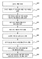
- FIG. 1 is a flowchart sequentially illustrating a method of generating a vehicle around view image according to the present invention.
- 2 to 7 are reference views for explaining a vehicle around view image generation process according to the present invention.
- FIG. 8 is a view for explaining a process for determining whether a pixel to be mapped is located inside a distortion polygon according to the present invention.
- FIG. 9 is a view for explaining a method of mapping a distortion polygon to a reference polygon in accordance with the present invention.
- FIG. 10 is a flowchart illustrating a process of selecting two reference vertices which are references when polygons are mapped in an embodiment of the present invention.
- FIG. 11 is a reference diagram for explaining the method of FIG. 10; FIG.
- FIG. 12 is a view illustrating an around view image finally combined in a vehicle around view generating method according to the present invention.
- FIGS. 2 to 7 are reference diagrams for explaining a process of generating a vehicle around view image according to the present invention.
- the following processing may be performed via a PC or may be processed by a process inside the vehicle.
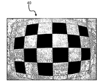
- the present invention generates a reference grid pattern corresponding to the reference check board pattern 10 shown in FIG. 2 (S10), and sets reference coordinate values for each intersection point of the grid pattern (S20).
- the reference image 20 in which the grid pattern image is divided into a plurality of reference polygons 30 is set.
- the plurality of reference polygons 30 are formed in a polygonal shape having vertices A ', B', and C '.
- a check board pattern is photographed by a plurality of wide-angle cameras, respectively, to obtain a distorted image 40 as shown in FIG. 3 (S40).
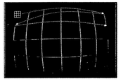
- the check board pattern of the distorted image 40 is recognized, and an edge of the check board pattern in the distorted image is detected as shown in FIG. 4 through morphology and robust operation (S50).
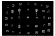
- a plurality of correction points are estimated and a correction order for the estimated correction points is selected (S60).
- the correction point estimation is estimated using the change in the brightness distribution in the vertical direction and the horizontal direction while performing line tracking along the detected edge region as shown in FIG. 5. That is, since the brightness variation is large at each intersection in the check board pattern, the point where the brightness variation is large during the line tracking process is estimated as a correction point and corrected according to the order estimated as the correction point as shown in FIG. 6. Select the order.
- the distortion points are divided into a plurality of distortion polygons having correction points A, B, and C (S70).
- each pixel coordinate of the distorted image is mapped to the reference coordinate so that the distorted polygon corresponds to the reference polygon according to the selected correction order, thereby obtaining each corrected image (S80). That is, each pixel in the distortion polygon 50 is mapped to the reference polygon 30 of the reference image. In this case, it is determined whether the pixel to be mapped is located inside the distortion polygon. If the pixel to be mapped is located inside the distortion polygon, the coordinates of the pixel are mapped to the reference coordinate. If the pixel to be mapped is not inside the distortion polygon, the mapping is performed. Exclude from the target.
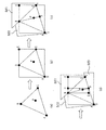
- FIG. 8 is a view for explaining a process for determining whether a pixel to be mapped is located inside a distortion polygon according to the present invention.
- First as shown in FIG. Check if it is located within the distortion polygon consisting of B and C. To this end, it is necessary to obtain the coordinates of the points D and E of the square including vertices A, B, and C as shown in FIG.
- a part outside the coordinate may be defined as outside.
- the outside range condition is if (P x ⁇ D x ⁇ P x > E x ⁇ P y ⁇ D y ⁇ P y > E y ), and if the outside range condition is not satisfied, the corresponding pixel to be mapped (P You can see that is located inside the rectangle.
- the mapping target pixel P is located outside the distortion polygon.
- the condition for the pixel to be mapped (P) outside the distortion polygon is the outer range condition if (F x ⁇ D x ⁇ F x > E x ⁇ F y ⁇ D y ⁇ F y > E y ), Point F is a line segment This is a case where the mapping target pixel P is located in the OUT1 or OUT2 region.
- the outside range condition for the mapping target pixel P to be located outside the distortion polygon is if (P x ⁇ G x ⁇ P x > H x ⁇ P y ⁇ G y ⁇ P y > H y ).
- the case where the pixel P is located outside the rectangle BGFH corresponds to the case where the pixel to be mapped is located in the OUT3 region.
- the pixel to be mapped P is located inside the distortion polygon.
- mapping target pixel P is located inside the distortion polygon, the corresponding pixel is mapped to correspond to the reference image.
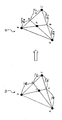
- FIG. 9 is a view for explaining a method of mapping a distorted polygon to a reference polygon according to the present invention.
- a first straight line passing through A) and the mapping target pixel P ) And the line segment facing the first reference vertex (A) The coordinate of the 1st intersection point (a) which () intersects is computed.
- one of the two except for the first reference vertex A is selected as the second reference vertex B, and a second straight line passing through the second reference vertex B and the mapping target pixel P ( ) And the line segment facing the second reference vertex (B)
- the coordinate of the 2nd intersection point (b) which () intersects is computed.
- the coordinates of the first intersection point a and the second intersection point b are obtained by the following equation.
- the coordinates of the points a and b are calculated by the following formula.
- mapping target pixel P is mapped in correspondence with the intersection point P'.
- the program recognizes the two line segments almost horizontally and an error occurs. Therefore, in order to correct such an error, the reference vertex should be selected such that the slope of two line segments passing through the mapping target pixel P faces the line segment sufficiently larger than the slope of each line segment of the polygon.
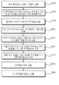
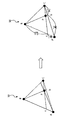
- FIG. 10 is a flowchart for explaining a process of selecting two reference vertices as reference points when mapping a polygon in an embodiment of the present invention
- FIG. 11 is a reference diagram for explaining the method of FIG. 10 and a point P in a triangle ABC.
- the distance between each vertex and P is compared, and the distance information between the vertex far from the point P and the point P is stored as dap (S200).
- the length of the dap and the dbp is compared to the point P and the longest vertex is determined by comparing the length of the dap and the dbp as shown in the following formula, and stored in the ABP. Determine the farthest vertex and store it in the ACP, compare the dbp and dcp lengths to determine the longest point as the farthest vertex and store the longest in the BCP.
- step S300 the slope between P and the vertex found in step S300 is calculated using the following formula (S400).
- the slope difference can be calculated. As the value approaches 0, the line segment passing through the pixel to be mapped P is closer to each line segment of the distortion polygon.
- FIG. 12 is a diagram illustrating an around view image that is finally combined in a method of generating a vehicle around view according to the present invention.
- Each of the correction images generated by the above-described method is combined with a planar image of a vehicle to generate an around view image. (S90).
Abstract
The present invention relates to a method for generating an image of the view around a vehicle, which involves estimating a polygon coordinate in a distortion image obtained through a wide-angle camera and polygon-mapping the estimated polygon coordinate into a standard image. To this end, the method for generating an image of the view around a vehicle according to the present invention involves correcting the radial distortion of an image obtained from a plurality of wide-angle cameras in order to generate a view image, and comprises the steps of: setting a standard coordinate value with respect to each intersection point of a standard grid pattern and generating a standard image divided by a plurality of standard polygons having standard vertices (A', B', C') with respect to a grid pattern image; capturing a checkerboard pattern using a plurality of wide-angle cameras to obtain each distortion image; detecting the edge of the checkerboard pattern in each distortion image; estimating a plurality of correction points by using brightness distribution change amounts in a vertical direction and in a parallel direction during line tracking along the detected edge area, and selecting a correction order for the estimated correction points; dividing each distortion image into a plurality of distortion polygons having correction vertices (A, B, C); mapping each pixel coordinate of the distortion image onto a standard coordinate in order to make a distortion polygon correspond to a standard polygon according to the correction order in order to obtain each correction image; and generating an image of the view around a vehicle by combining each correction image with a vehicle plane image.
Description
본 발명은 차량 어라운드 뷰 영상 생성 방법에 관한 것으로, 특히 광각 카메라를 통해 획득되는 왜곡 영상 내의 폴리곤 좌표점을 추정하고, 추정된 폴리곤 좌표점을 기준 영상에 폴리곤 매핑되도록 하는 차량 어라운드 뷰 영상 생성 방법에 관한 것이다.The present invention relates to a method for generating a vehicle around view image, and more particularly, to a method for generating a vehicle around view image for estimating a polygon coordinate point in a distorted image obtained through a wide-angle camera and for performing a polygon mapping of the estimated polygon coordinate point to a reference image. It is about.
차량에는 주행의 편리성 제공, 교통 사고 발생시 사고 원인 분석 등의 목적으로 전, 후방 등 여러 위치에 카메라가 설치되는 경우가 많다. 특히, 근래에는 차량의 후측면에 카메라를 설치하여 차량 후진시 후방 영상을 제공하여 주차의 편리성을 제공하고 있다. In many cases, cameras are installed at various locations, such as front and rear, for the purpose of providing convenience of driving and analyzing the cause of an accident when a traffic accident occurs. In particular, in recent years, a camera is installed on the rear side of the vehicle to provide a rear image when the vehicle is reversed, thereby providing convenience of parking.
이러한 후방 영상 제공을 위해서는 넓은 시야를 확보할 수 있는 광각 카메라가 주로 사용되는데, 광각 카메라는 외각 부분으로 갈수록 해상도가 떨어질 뿐만 아니라 외각 부분으로 갈수록 영상이 휘어지는 왜곡, 즉 방사 왜곡(radial distortion)이 두드러진다.To provide such a rear image, a wide-angle camera that can secure a wide field of view is mainly used. A wide-angle camera not only has a lower resolution toward the outer portion, but also a distortion, ie, radial distortion, that is contorted toward the outer portion. .
따라서, 이러한 왜곡된 영상을 보정하는 처리가 필요하게 되는데, 왜곡 영상은 일반적으로 워핑 방정식을 이용하여 교정하는 것이 일반적이다. 워핑 방정식은 다음 수식과 같이 1차, 2차, 3차 방정식으로 표현된다.Therefore, there is a need for a process of correcting such a distorted image, which is generally corrected using a warping equation. The warping equation is expressed as a first-order, second-order, or third-order equation as shown in the following equation.
수식 1 Equation 1
수식 2 Equation 2
수식 3 Equation 3
왜곡 영상의 교정에 있어서는 격자(바둑판) 형상의 표준 그리드 이미지를 이용하여 워핑 파라미터를 산출한 후이를 모든 픽셀에 적용하게 되는데 이러한 워핑 방정식을 적용하기 위해서는 표준 그리드 이미지의 교차점들의 좌표값과 광각 카메라로 촬상하여 얻어지는 왜곡 그리드 이미지 상의 교차점들의 좌표값을 알아야 한다. In the correction of the distortion image, a warping parameter is calculated using a grid-shaped standard grid image and then applied to all pixels. To apply this warping equation, the coordinate values of the intersection points of the standard grid image and the wide angle camera are used. It is necessary to know the coordinate values of the intersection points on the distortion grid image obtained by imaging.
그러나, 종래의 경우 이러한 표준 그리드 이미지의 교차점들의 좌표값과 광각 카메라로 촬상하여 얻어지는 왜곡 그리드 이미지 상의 교차점들의 좌표값들은 수작업을 통해 직접 구해야하므로 테스트 포인트가 많을 경우 시간이 많이 소요되는 단점이 있다. However, in the related art, the coordinate values of the intersection points of the standard grid image and the coordinate values of the intersection points on the distorted grid image obtained by capturing with the wide-angle camera must be directly obtained by hand.
한편, 차량의 후방 카메라의 경우 후방 주차시 상당한 도움이 되는 것은 사실이나, 차량의 후방 영상만 제공하므로 차량 전방이나 좌우방향의 상황을 파악할 수 없어 주변의 모든 상황을 완전하게 인지하지 못한 채로 주차를 하여야 한다는 단점도 있다.On the other hand, in the case of the rear camera of the vehicle, it is very helpful for rear parking, but since only the rear image of the vehicle is provided, it is impossible to grasp the situation in front of the vehicle or in the left and right directions, so the parking is not completely recognized without knowing all the surroundings. There is also a disadvantage.
또한, 종래의 왜곡 보정 방법은 워핑 방정식을 이용함에도 불구하고 왜곡이 완벽하게 보정되지 않는 단점이 있다.In addition, the conventional distortion correction method has a disadvantage that the distortion is not completely corrected despite the use of the warping equation.
배경 기술의 단점을 해결하기 위한 본 발명의 목적은 기준 그리드 패턴을 복수의 기준 폴리곤으로 분할 설정하고, 광각 카메라를 통해 획득되는 왜곡 영상을 복수의 왜곡 폴리곤으로 분할한 후에 각 왜곡 폴리곤의 좌표점을 자동으로 추정하고, 추정된 왜곡 폴리곤이 기준 폴리곤에 대응되도록 왜곡 폴리곤의 각 좌표점을 기준 폴리곤에 매핑하여, 왜곡된 영상의 선택 영역을 보정하고자 하는 위치로 자유 변형 및 위치 이동을 함으로써 왜곡을 보정할 수 있도록 하는 차량 어라운드 뷰 영상 생성 방법을 제공함에 있다.An object of the present invention for solving the disadvantages of the background technology is to divide the reference grid pattern into a plurality of reference polygons, and to divide the distortion image obtained by the wide-angle camera into a plurality of distortion polygons, and then to coordinate the coordinate points of each distortion polygon. Automatically estimates and corrects the distortion by mapping each coordinate point of the distortion polygon to the reference polygon so that the estimated distortion polygon corresponds to the reference polygon, and freely transforming and shifting the position of the distorted image to the position to be corrected. The present invention provides a method of generating a vehicle around view image.
본 발명의 다른 목적은 폴리곤 매핑 방식에 의해 보정된 차량의 전,후,좌,우에서 촬영한 외부 영상들을 조합하여 단일의 어라운드 뷰 영상을 생성 및 디스플레이하는 차량 어라운드 뷰 영상 생성 방법을 제공함에 있다. Another object of the present invention is to provide a vehicle around view image generation method for generating and displaying a single around view image by combining external images taken from the front, rear, left and right of the vehicle corrected by the polygon mapping method. .
과제를 해결하기 위한 본 발명의 차량의 어라운드 뷰 영상 생성 방법은, 복수의 광각 카메라로부터 획득된 영상의 방사 왜곡을 보정하여 어라운드 뷰 영상을 생성하는 방법에 있어서, 기준 그리드 패턴의 각 교차점에 대한 기준 좌표값을 설정하고 그리드 패턴 영상에 대하여 기준 꼭지점(A',B',C')을 갖는 복수의 기준 폴리곤으로 분할한 기준 영상을 생성하는 단계, 복수의 광각 카메라로 체크 보드 패턴을 촬상하여 각각의 왜곡 영상을 획득하는 단계, 각 왜곡 영상 내 체크 보드 패턴의 에지를 검출하는 단계, 검출된 에지 영역을 따라 라인 트레킹을 수행하면서 수직 방향과 수평 방향으로의 밝기 분포 변화량을 이용하여 복수의 보정점을 추정하고, 추정된 보정점들에 대한 보정 순서를 선정하는 단계, 각 왜곡 영상에 대하여 보정 꼭지점(A,B,C)으로 하는 복수의 왜곡 폴리곤으로 분할하는 단계, 보정 순서에 따라 왜곡 폴리곤이 기준 폴리곤에 대응되도록 왜곡 영상의 각 픽셀 좌표를 기준 좌표에 매핑하여 각각의 보정 영상을 획득하는 단계 및 각각의 보정 영상과 차량의 평면 영상을 조합하여 어라운드 뷰 영상을 생성하는 단계를 포함한다.In the method of generating an around view image of a vehicle according to the present invention, a method of generating an around view image by correcting a radial distortion of an image obtained from a plurality of wide-angle cameras, the reference for each intersection point of a reference grid pattern Setting a coordinate value and generating a reference image obtained by dividing a plurality of reference polygons having reference vertices A ', B', and C 'with respect to the grid pattern image. Obtaining a distorted image of the image, detecting an edge of a check board pattern in each distorted image, and performing a line trek along the detected edge region, using a change in brightness distribution in a vertical direction and a horizontal direction. Estimating the corrected vertex (A, B, C) for each distortion image Dividing into a plurality of distortion polygons, acquiring each correction image by mapping each pixel coordinate of the distortion image to the reference coordinate so that the distortion polygon corresponds to the reference polygon according to the correction order, and obtaining each correction image and the plane of the vehicle Combining the images to generate an around view image.
여기서, 어라운드 뷰 영상 생성 단계는 복수의 보정 영상에서 상호 인접한 코너 영역의 중복 영상을 제거하되, 각 보정 영상들에 대하여 외측 모서리 부분에서 내측 방향으로 경사진 기준 선분을 설정하고, 인접한 보정 영상들을 기준 선분이 일치 되도록 중첩시켜 중복 영상을 제거한다. Here, the step of generating an around view image may remove overlapping images of adjacent corner areas from a plurality of correction images, set reference line segments inclined inward from an outer edge portion of each of the correction images, and reference adjacent correction images. Overlapping images are removed by overlapping line segments.
또한, 왜곡 폴리곤과 기준 폴리곤 매핑 단계는 매핑 대상 픽셀이 왜곡 폴리곤 내부에 위치하는지 판단하고, 매핑 대상 픽셀이 상기 왜곡 폴리곤 내부에 위치하는 경우에만 매핑을 수행한다. In addition, the mapping of the distortion polygon and the reference polygon determines whether the pixel to be mapped is located inside the distortion polygon, and performs mapping only when the pixel to be mapped is located inside the distortion polygon.
그리고, 왜곡 영상의 픽셀 좌표를 기준 좌표에 매핑하는 단계는 꼭지점 A, B, C 중 어느 하나를 제 1 기준 꼭지점을 선정하고, 제 1 기준 꼭지점과 매핑 대상 픽셀(P)을 지나는 제 1 직선 및 상기 제 1 기준 꼭지점과 마주보는 선분과의 교차점 좌표를 산출하는 제 1 교차점 좌표 산출 단계와, 꼭지점 A, B, C 중 제 1 기준 꼭지점을 제외한 둘 중 하나를 제 2 기준 꼭지점으로 선정하고, 제 2 기준 꼭지점과 매핑 대상 픽셀(P)을 지나는 제 2 직선 및 상기 제 2 기준 꼭지점과 마주보는 선분과의 교차점 좌표를 산출하는 제 2 교차점 좌표 산출 단계와, 제 1 직선 상의 제 1 교차점 좌표비와 제 2 직선 상의 제 2 교차점 좌표비를 산출하는 단계와, 제 1 교차점 좌표비를 기준 폴리곤의 꼭지점(A',B',C')에 대응시켜 기준 폴리곤 상의 제 3 교차점 좌표를 산출하고, 제 2 교차점 좌표비를 기준 폴리곤의 꼭지점(A',B',C')에 대응시켜 기준 폴리곤 상의 제 4 교차점 좌표를 산출하는와, 제 3 교차점과 제 4 교차점 각각과 마주하는 제 3 꼭지점과 제 4 꼭지점을 추출하고, 제 3꼭지점과 제 3 교차점을 잇는 제 3 선분 및 제 4 교차점과 제 4꼭지점을 잇는 제 4 선분을 추출하여, 제 3 선분과 제 4 선분의 교차점(P')를 산출하는 단계, 및 매핑 대상 픽셀(P)을 교차점(P')에 대응시켜 매핑하는 단계를 포함한다. The mapping of the pixel coordinates of the distorted image to the reference coordinates may include selecting a first reference vertex from any one of vertices A, B, and C, a first straight line passing through the first reference vertex and the mapping target pixel P, and Calculating a first coordinate of the intersection point of the line segment facing the first reference vertex, and selecting one of the vertices A, B, and C except for the first reference vertex as the second reference vertex, and A second intersection coordinate calculation step of calculating intersection coordinates between a second reference vertex and a second straight line passing through the mapping target pixel P and a line segment facing the second reference vertex, and a first intersection coordinate ratio on the first straight line and Calculating a second intersection coordinate ratio on the second straight line, and calculating a third intersection coordinate on the reference polygon by mapping the first intersection coordinate ratio to vertices A ', B', and C 'of the reference polygon, 2 crossing left Comparing the ratios to vertices A ', B', C 'of the reference polygon to calculate the fourth intersection coordinates on the reference polygon, and extracting third and fourth vertices facing each of the third and fourth intersection points. Extracting a third segment connecting the third vertex and the third intersection point and a fourth segment connecting the fourth vertex and the fourth vertex to calculate an intersection point P ′ of the third segment and the fourth segment; and And mapping the mapping target pixel P to the intersection point P '.
또한, 제 1 기준 꼭지점 선정은 왜곡 폴리곤의 세 선분의 기울기를 산출하는 제 1 기울기 산출 단계와, 매핑 대상 픽셀(P)과 각 꼭지점(A,B,C)과의 거리를 산출하는 단계와, 매핑 대상 픽셀(P)과 각 꼭지점을 연결하여 3개의 삼각형을 구하고, 각각의 삼각형에 대하여 꼭지점과 매핑 대상 픽셀(P) 간의 거리가 먼 꼭지점을 각각 추출하는 단계와, 매핑 대상 픽셀(P)과 거리가 먼 꼭지점들과 매핑 대상 픽셀(P)과 기울기를 산출하는 제 2 기울기 산출 단계와, 제 1 기울기와 제 2 기울기의 차를 산출하고 기울기 차가 가장 작은 선분을 추출하는 단계와, 기울기의 차가 가장 작은 선분과 마주보는 꼭지점을 제 1 기준 꼭지점으로 선정하는 단계로 이루어진다.In addition, the first reference vertex selection may include calculating a first slope for calculating three slopes of the distorted polygon, calculating a distance between the mapping target pixel P and each vertex A, B, and C; Extracting three triangles by connecting the mapping target pixel P and each vertex, and extracting vertices far from the vertex and the mapping target pixel P, respectively, for each triangle; Calculating a second slope, calculating a difference between the first vertex and the second slope, extracting a line segment having the smallest difference between the vertices, and the mapping target pixel P; A vertex facing the smallest line segment is selected as the first reference vertex.
또한, 제 2 기준 꼭지점은 매핑 대상 픽셀(P)과의 거리 산출 결과 거리가 가장 가까운 꼭지점으로 선정한다.In addition, the second reference vertex is selected as a vertex closest to the distance as a result of calculating the distance to the mapping target pixel P.
본 발명은 폴리곤 매핑 방식을 이용하여 왜곡된 영상의 선택 영역을 보정하고자 하는 위치로 자유 변형 및 위치 이동을 함으로써 왜곡을 완벽하게 보정할 수 있는 이점이 있다.The present invention has the advantage that the distortion can be completely corrected by freely transforming and shifting the position to a position to correct the selected region of the distorted image using the polygon mapping method.
또한, 본 발명은 왜곡 영상 내의 복수의 왜곡 폴리곤이 기준 영상의 기준 폴리곤에 자동으로 추정되도록 함으로써, 왜곡 영상에 대한 보정이 자동으로 이루어지도록 하는 이점이 있다.In addition, the present invention has an advantage in that a plurality of distortion polygons in the distorted image are automatically estimated to the reference polygons of the reference image, thereby automatically correcting the distortion image.
또한, 본 발명은 차량의 전,후,좌,우에서 촬영한 외부 영상들을 조합하여 단일의 어라운드 뷰 영상을 생성 및 디스플레이함으로써 주차시 사각지대를 제거할 수 있어 원활한 주차가 가능하도록 하는 이점이 있다.In addition, the present invention has the advantage that the blind spots can be removed when parking by combining and generating a single around view image by combining the external images taken from the front, rear, left, right of the vehicle to enable smooth parking. .
도 1은 본 발명에 따른 차량 어라운드 뷰 영상 생성 방법을 순차로 나타낸 흐름도.1 is a flowchart sequentially illustrating a method of generating a vehicle around view image according to the present invention.
도 2 내지 도 7은 본 발명에 따른 차량 어라운드 뷰 영상 생성 과정을 설명하기 위한 참조도.2 to 7 are reference views for explaining a vehicle around view image generation process according to the present invention.
도 8은 본 발명에 따라 매핑 대상 픽셀이 왜곡 폴리곤 내부에 위치하는지 여부를 판단하기 위한 과정을 설명하기 위한 도면.8 is a view for explaining a process for determining whether a pixel to be mapped is located inside a distortion polygon according to the present invention.
도 9는 본 발명에 따라 왜곡 폴리곤을 기준 폴리곤으로 매핑하는 방법을 설명하기 위한 도면.9 is a view for explaining a method of mapping a distortion polygon to a reference polygon in accordance with the present invention.
도 10은 본 발명의 실시예에서 폴리곤 매핑시 기준이 되는 두개의 기준 꼭지점을 선정하는 과정을 설명하기 위한 흐름도.FIG. 10 is a flowchart illustrating a process of selecting two reference vertices which are references when polygons are mapped in an embodiment of the present invention. FIG.
도 11은 도 10의 방법을 설명하기 위한 참조 도면.FIG. 11 is a reference diagram for explaining the method of FIG. 10; FIG.
도 12는 본 발명에 따른 차량 어라운드 뷰 생성 방법에서 최종적으로 조합되는 어라운드 뷰 영상을 도시한 도면.12 is a view illustrating an around view image finally combined in a vehicle around view generating method according to the present invention;
이하에서는 첨부된 도면을 참조하여 본 발명의 바람직한 일 실시예를 상세하게 설명하기로 한다. Hereinafter, with reference to the accompanying drawings will be described in detail a preferred embodiment of the present invention.
도 1은 본 발명에 따른 차량 어라운드 뷰 영상 생성 방법을 순차로 나타낸 흐름도이고, 도 2 내지 도 7은 본 발명에 따른 차량 어라운드 뷰 영상 생성 과정을 설명하기 위한 참조도이다. 이하의 처리 과정은 PC를 통해 수행될 수 있고, 차량 내부의 프로세스에 의해 처리될 수도 있다. 1 is a flowchart sequentially illustrating a method of generating a vehicle around view image according to the present invention, and FIGS. 2 to 7 are reference diagrams for explaining a process of generating a vehicle around view image according to the present invention. The following processing may be performed via a PC or may be processed by a process inside the vehicle.
우선, 본 발명은 도 2에 도시된 기준 체크 보드 패턴(10)에 대응하는 기준 그리드 패턴을 생성하고(S10), 그리드 패턴의 각 교차점에 대한 기준 좌표값을 설정한다(S20). 그리고, 그리드 패턴 영상을 복수의 기준 폴리곤(30)으로 분할 설정한 기준 영상(20)을 생성한다(S30). 이때, 복수의 기준 폴리곤(30)은 꼭지점(A',B',C')을 갖는 폴리곤 형태로 이루어진다. First, the present invention generates a reference grid pattern corresponding to the reference check board pattern 10 shown in FIG. 2 (S10), and sets reference coordinate values for each intersection point of the grid pattern (S20). In operation S30, the reference image 20 in which the grid pattern image is divided into a plurality of reference polygons 30 is set. In this case, the plurality of reference polygons 30 are formed in a polygonal shape having vertices A ', B', and C '.
다음으로, 복수의 광각 카메라로 각각 체크 보드 패턴을 촬상하여 도 3에 도시된 바와 같이 왜곡된 영상(40)을 획득한다(S40). Next, a check board pattern is photographed by a plurality of wide-angle cameras, respectively, to obtain a distorted image 40 as shown in FIG. 3 (S40).
이어서, 왜곡 영상(40)의 체크 보드 패턴을 인식하고, 모폴로지 및 로버스트 연산을 통해 도 4에 도시된 바와 같이 왜곡 영상 내 체크 보드 패턴의 에지를 검출한다(S50).Next, the check board pattern of the distorted image 40 is recognized, and an edge of the check board pattern in the distorted image is detected as shown in FIG. 4 through morphology and robust operation (S50).
체크 보드 패턴의 에지가 검출되면, 복수의 보정점을 추정하고 추정된 보정점들에 대한 보정 순서를 선정한다(S60). 이때, 보정점 추정은 도 5에 도시된 바와 같이 검출된 에지 영역을 따라 라인 트레킹을 수행하면서, 수직 방향과 수평 방향으로의 밝기 분포 변화량을 이용하여 추정한다. 즉, 체크 보드 패턴에서의 각 교차점에서는 밝기 변화량이 크게 나타나므로, 라인 트레킹 과정에서 밝기 변화량이 크게 나타나는 점을 보정점으로 추정하고, 도 6에 도시된 바와 같이 보정점으로 추정된 순서에 따라 보정 순서를 선정한다.When the edge of the check board pattern is detected, a plurality of correction points are estimated and a correction order for the estimated correction points is selected (S60). At this time, the correction point estimation is estimated using the change in the brightness distribution in the vertical direction and the horizontal direction while performing line tracking along the detected edge region as shown in FIG. 5. That is, since the brightness variation is large at each intersection in the check board pattern, the point where the brightness variation is large during the line tracking process is estimated as a correction point and corrected according to the order estimated as the correction point as shown in FIG. 6. Select the order.
이어서, 왜곡 영상에 대하여 보정점들을 꼭지점(A,B,C)으로 하는 갖는 복수의 왜곡 폴리곤으로 분할한다(S70). Subsequently, the distortion points are divided into a plurality of distortion polygons having correction points A, B, and C (S70).
그리고, 도 7에 도시된 바와 같이 선정된 보정 순서에 따라 왜곡 폴리곤이 기준 폴리곤에 대응되도록 왜곡 영상의 각 픽셀 좌표를 기준 좌표에 매핑하여 각각의 보정 영상을 획득한다(S80). 즉, 왜곡 폴리곤(50) 내의 각 픽셀을 기준 영상의 기준 폴리곤(30)에 매핑한다. 이때, 매핑 대상 픽셀이 왜곡 폴리곤 내부에 위치하는지 판단하고, 매핑 대상 픽셀이 왜곡 폴리곤 내부에 위치하는 경우 해당 픽셀의 좌표를 기준 좌표에 매핑하고, 매핑 대상 픽셀이 왜곡 폴리곤 내부에 위치하지 않을 경우 매핑 대상에서 제외한다.As shown in FIG. 7, each pixel coordinate of the distorted image is mapped to the reference coordinate so that the distorted polygon corresponds to the reference polygon according to the selected correction order, thereby obtaining each corrected image (S80). That is, each pixel in the distortion polygon 50 is mapped to the reference polygon 30 of the reference image. In this case, it is determined whether the pixel to be mapped is located inside the distortion polygon. If the pixel to be mapped is located inside the distortion polygon, the coordinates of the pixel are mapped to the reference coordinate. If the pixel to be mapped is not inside the distortion polygon, the mapping is performed. Exclude from the target.
이하에서는 도 8 내지 도 10을 참조하여 본 발명에 따른 왜곡 폴리곤을 기준 폴리곤으로 매핑하는 과정을 더욱 상세하게 설명하도록 한다. Hereinafter, a process of mapping the distortion polygon according to the present invention to the reference polygon will be described in more detail with reference to FIGS. 8 to 10.
도 8은 본 발명에 따라 매핑 대상 픽셀이 왜곡 폴리곤 내부에 위치하는지 여부를 판단하기 위한 과정을 설명하기 위한 도면으로서, 우선, 도 8의 (a)와 같이 검사 대상 픽셀(P)이 꼭지점 A,B,C로 이루어진 왜곡 폴리곤 내에 위치하는지 확인한다. 이를 위해서는, 도 8의 (b)와 같이 꼭지점 A,B,C를 포함하는 정사각형의 점 D와 E의 좌표를 구해야한다. 8 is a view for explaining a process for determining whether a pixel to be mapped is located inside a distortion polygon according to the present invention. First, as shown in FIG. Check if it is located within the distortion polygon consisting of B and C. To this end, it is necessary to obtain the coordinates of the points D and E of the square including vertices A, B, and C as shown in FIG.
이때, D와 E의 좌표는 아래의 수식을 이용하여 구할 수 있다.At this time, the coordinates of D and E can be obtained using the following equation.
이와 같은 좌표를 구하고 매핑 대상 픽셀(P)이 꼭지점 A,B,C를 포함하는 정사각형 범위가 지정되면 이 좌표를 벗어나는 부분을 outside로 정할 수 있다. 이때, outside의 범위 조건은 if(Px<Dx ∥Px>Ex ∥ Py<Dy ∥Py>Ey)으로서, outside의 범위 조건을 만족하지 않을 경우 해당 매핑 대상 픽셀(P)이 사각형 내부에 위치하는 것을 알 수 있다.If such a coordinate is obtained and a square range including the vertices A, B, and C of the pixel to be mapped P is specified, a part outside the coordinate may be defined as outside. At this time, the outside range condition is if (P x <D x ∥P x > E x ∥ P y <D y ∥P y > E y ), and if the outside range condition is not satisfied, the corresponding pixel to be mapped (P You can see that is located inside the rectangle.
그리고, 매핑 대상 픽셀(P)이 꼭지점 A,B,C를 포함하는 폴리곤 내부에 위치하는지 확인하기 위해서 도 8의 (c)와 같이  와
와  가 만나는 점 F의 좌표를 찾는다. 이때, F는 아래의 수식에 의해 구할 수 있다.In addition, as shown in FIG. 8C, in order to check whether the mapping target pixel P is located inside a polygon including vertices A, B, and C. Wow Find the coordinate of the point F where In this case, F can be obtained by the following equation.
F=cross( ,
, )F = cross ( , )
이렇게, 점 F의 좌표가 구해지면 매핑 대상 픽셀(P)이 왜곡 폴리곤 외부에 위치하는지 여부를 확인한다. 여기서, 매핑 대상 픽셀(P)이 왜곡 폴리곤 외부에 위치하기 위한 조건은 outside 범위 조건은 if(Fx<Dx ∥ Fx>Ex ∥ Fy<Dy ∥ Fy>Ey)로서, 점 F가 선분( )를 벗어난 경우로서 매핑 대상 픽셀(P)이 OUT1 또는 OUT2 영역에 위치하는 경우에 해당한다. In this way, when the coordinates of the point F are obtained, it is checked whether the mapping target pixel P is located outside the distortion polygon. Here, the condition for the pixel to be mapped (P) outside the distortion polygon is the outer range condition if (F x <D x ∥ F x > E x ∥ F y <D y ∥ F y > E y ), Point F is a line segment This is a case where the mapping target pixel P is located in the OUT1 or OUT2 region.
그리고, 도 8의 (d)에 도시된 바와 같이 매핑 대상 픽셀(P)을 기준으로 연결된 점 B와 F가 꼭지점이 되는 사각형의 점 G와 H의 좌표를 구한다. Then, as shown in (d) of FIG. 8, the coordinates of the points G and H of the quadrangular points B and F, which are connected to the mapping target pixel P, are vertices are obtained.
이때, G와 H의 좌표는 아래의 수식을 이용하여 구할 수 있다.At this time, the coordinates of G and H can be obtained using the following equation.
이렇게, G와 H의 좌표가 구해지면 매핑 대상 픽셀(P)이 사각형(BGFH) 외부에 위치하는지 확인한다. 여기서, 매핑 대상 픽셀(P)이 왜곡 폴리곤 외부에 위치하기 위한 outside 범위 조건은 if(Px<Gx ∥ Px>Hx ∥Py <Gy ∥Py>Hy)로서, 매핑 대상 픽셀(P)이 사각형 BGFH 외부에 위치하는지 경우는 매핑 대상 픽셀이 OUT3 영역에 위치하는 경우에 해당한다. In this way, when the coordinates of G and H are obtained, it is checked whether the mapping target pixel P is located outside the rectangle BGFH. Here, the outside range condition for the mapping target pixel P to be located outside the distortion polygon is if (P x <G x ∥ P x > H x ∥P y <G y ∥P y > H y ). The case where the pixel P is located outside the rectangle BGFH corresponds to the case where the pixel to be mapped is located in the OUT3 region.
이와 같은 outside 범위 조건 확인 결과 outside 범위 조건에 해당하지 않으면 매핑 대상 픽셀(P)이 왜곡 폴리곤 내부에 위치하는 것을 알 수 있다.As a result of checking the outside range condition, if the outside range condition does not correspond, the pixel to be mapped P is located inside the distortion polygon.
한편, 매핑 대상 픽셀(P)이 왜곡 폴리곤 내부에 위치하는 것으로 판단되면, 해당 픽셀을 기준 영상에 대응되도록 매핑한다. If it is determined that the mapping target pixel P is located inside the distortion polygon, the corresponding pixel is mapped to correspond to the reference image.
도 9는 본 발명에 따라 왜곡 폴리곤을 기준 폴리곤으로 매핑하는 방법을 설명하기 위한 도면으로서, 우선 꼭지점 A, B, C 중 어느 하나를 제 1 기준 꼭지점(A)으로 선정하고, 제 1 기준 꼭지점(A)과 매핑 대상 픽셀(P)을 지나는 제 1 직선( ) 및 제 1 기준 꼭지점(A)과 마주보는 선분(
 )이 교차하는 제 1 교차점(a)의 좌표를 산출한다. 그리고, 제 1 기준 꼭지점(A)을 제외한 둘 중 하나를 제 2 기준 꼭지점(B)으로 선정하고, 제 2 기준 꼭지점(B)과 매핑 대상 픽셀(P)을 지나는 제 2 직선(
 ) 및 제 2 기준 꼭지점(B)과 마주보는 선분(
 )이 교차하는 제 2 교차점(b)의 좌표를 산출한다. FIG. 9 is a view for explaining a method of mapping a distorted polygon to a reference polygon according to the present invention. A first straight line passing through A) and the mapping target pixel P ) And the line segment facing the first reference vertex (A) The coordinate of the 1st intersection point (a) which () intersects is computed. Then, one of the two except for the first reference vertex A is selected as the second reference vertex B, and a second straight line passing through the second reference vertex B and the mapping target pixel P ( ) And the line segment facing the second reference vertex (B) The coordinate of the 2nd intersection point (b) which () intersects is computed.
여기서, 제 1 교차점(a)과 제 2 교차점(b)의 좌표는 아래의 수식에 의해 구해진다.Here, the coordinates of the first intersection point a and the second intersection point b are obtained by the following equation.
a=CROSS( ,
, )a = CROSS ( , )
b=CROSS( ,
, )b = CROSS ( , )
이어서, 선분  에 대한 b의 좌표비(
 :
:  ) 및 선분
  에 대한 a의 좌표비(
 :
:  )를 산출하고, 산출된 b의 좌표비(
 :
:  ) 및 a의 좌표비(
 :
:  )를 기준 폴리곤의 꼭지점(A',B',C')에 대응시켜 선분
  상의 점 a'의 좌표와 선분
  상의 점 b '의 좌표를 산출한다.Then, line segment Coordinate ratio of b to : ) And line segment Coordinate ratio of a to : ) And calculate the coordinate ratio of : ) And the coordinate ratio of a ( : ) Corresponding to the vertices (A ', B', C ') of the reference polygon And line segment at point a 'on Pinterest Calculate the coordinates of point b 'on the phase.
여기서, 점 a와 b의 좌표는 아래의 수식에 의해 산출된다.Here, the coordinates of the points a and b are calculated by the following formula.
이러한 방식에 의해 점 a'와 b'의 좌표가 산출되면 A'와 a'를 잇는 선분( )와 꼭지점 B'와 b'를 잇는 선분(
 )의 교차점(P')를 산출한다. In this way, when the coordinates of points a 'and b' are calculated, the segment connecting A 'and a' ( ) And the line connecting vertices B 'and b' ( The intersection point P 'of () is calculated.
여기서, P'의 좌표는 아래의 수식에 의해 산출된다.Here, the coordinate of P 'is calculated by the following formula.
P'=CROSS( ,
, )P '= CROSS ( , )
이와 같이 교차점(P')의 좌표가 산출되면, 매핑 대상 픽셀(P)을 교차점(P')에 대응시켜 매핑한다.When the coordinates of the intersection point P 'are calculated in this way, the mapping target pixel P is mapped in correspondence with the intersection point P'.
그런데, 매핑 대상 픽셀(P)을 지나는 두개의 선분이 폴리곤의 어느 한 선분 근접하여 기울기의 차이가 거의 없을 때 프로그램을 두 선분을 거의 수평하게 인식하게 되어 오차가 발생한다. 따라서, 이러한 오차를 보정하기 위해서는 매핑 대상 픽셀(P)을 지나는 두개의 선분의 기울기가 폴리곤의 각 선분의 기울기보다 충분히 큰 선분과 마주보는 점을 기준 꼭지점으로 선정해야 한다. However, when two line segments passing through the mapping target pixel P have almost no difference in inclination close to any one line segment of the polygon, the program recognizes the two line segments almost horizontally and an error occurs. Therefore, in order to correct such an error, the reference vertex should be selected such that the slope of two line segments passing through the mapping target pixel P faces the line segment sufficiently larger than the slope of each line segment of the polygon.
도 10은 본 발명의 실시예에서 폴리곤 매핑시 기준이 되는 두개의 기준 꼭지점을 선정하는 과정을 설명하기 위한 흐름도이고, 도 11은 도 10의 방법을 설명하기 위한 참조 도면으로서, 삼각형 ABC내의 점 P를 삼각형 A'B'C'로 매핑하고자 할 경우 점 P의 좌표와 꼭지점 ABC의 좌표 및  ,
,  ,
,  의 선분비가 필요하며, 점 P를 매핑하기 위해 최적의 선분비 2개를 선택해야 한다.FIG. 10 is a flowchart for explaining a process of selecting two reference vertices as reference points when mapping a polygon in an embodiment of the present invention, and FIG. 11 is a reference diagram for explaining the method of FIG. 10 and a point P in a triangle ABC. To map to the triangle A'B'C ', the coordinates of point P and the vertex ABC, , , You need to select the line ratio of and choose the two best line ratios to map point P.
우선, 아래의 수식을 이용하여 왜곡 폴리곤 세 선분( )의 기울기를 산출한다(S100). First, using the equation Calculate the slope of (S100).
ab=SLOPE(A,B)ab = SLOPE (A, B)
ac=SLOPE(A,C)ac = SLOPE (A, C)
bc=SLOPE(B,C)bc = SLOPE (B, C)
그리고, 각 꼭지점과 P의 거리를 비교하고, 점 P에서 거리가 먼 꼭지점과 점 P와의 거리 정보를 dap로 저장한다(S200).The distance between each vertex and P is compared, and the distance information between the vertex far from the point P and the point P is stored as dap (S200).
구체적으로는, 아래의 수식과 같이 점 p에서 A, B의 길이를 비교하여 긴것을 dap에 저장하고, 점 p에서 A, C의 길이를 비교하여 긴것을 dbp에 저장하며, 점 p에서 B, C의 길이를 비교하여 긴 것을 dcp에 저장한다.Specifically, compare the lengths of A and B at point p and store the long ones in dap, compare the lengths of A and C at point p, and store the long ones in dbp, and store points B and B, Compare the lengths of C and store the long one in dcp.
dap=DIST(A,B)dap = DIST (A, B)
dbp=DIST(A,C)dbp = DIST (A, C)
dcp=DIST(B,C)dcp = DIST (B, C)
이어서, 점 P와 거리가 먼 꼭지점을 찾아 정보를 저장한다(S300).Subsequently, a vertex far from the point P is found to store information (S300).
구체적으로는, 아래의 수식과 같이 dap와 dbp의 길이를 비교하여 길이가 긴 것을 점 P와 가장 먼 꼭지점으로 판단하고 ABP에 저장하고, dap와 dcp의 길이를 비교하여 길이가 긴 것을 점 P와 가장 먼 꼭지점으로 판단하고 ACP에 저장하며, dbp와 dcp의 길이를 비교하여 길이가 긴 것을 점 P와 가장 먼 꼭지점으로 판단하고 긴 것을 BCP에 저장한다.Specifically, the length of the dap and the dbp is compared to the point P and the longest vertex is determined by comparing the length of the dap and the dbp as shown in the following formula, and stored in the ABP. Determine the farthest vertex and store it in the ACP, compare the dbp and dcp lengths to determine the longest point as the farthest vertex and store the longest in the BCP.
ABP=dap<dbp(=B) or dap>dbp(A)ABP = dap <dbp (= B) or dap> dbp (A)
ACP=dap<dcp(=C) or dap>dcp(A)ACP = dap <dcp (= C) or dap> dcp (A)
BCP=dbp<dcp(=C) or dbp>dcp(B)BCP = dbp <dcp (= C) or dbp> dcp (B)
그리고, 아래의 수식을 이용하여 P와 단계 S300에서 찾은 꼭지점과의 기울기를 산출한다(S400).Then, the slope between P and the vertex found in step S300 is calculated using the following formula (S400).
abp=SLOPE(P, ABP)abp = SLOPE (P, ABP)
acp=SLOPE(P, ACP)acp = SLOPE (P, ACP)
bcp=SLOPE(P, BCP)bcp = SLOPE (P, BCP)
이어서, S100 단계에서 산출한 기울기와, S400 단계에서 산출한 기울기의 차를 아래의 수식을 이용하여 산출한다(S500).Next, the difference between the slope calculated in step S100 and the slope calculated in step S400 is calculated by using the following formula (S500).
sdap=ABS(ab,abp)sdap = ABS (ab, abp)
sdbp=ABS(ab,abp)sdbp = ABS (ab, abp)
sdap=ABS(ab,abp)sdap = ABS (ab, abp)
이러한 방식에 의해 산출된 값에 대한 절대값을 취하면 기울기 차를 산출할 수 있으며, "0"에 가까울수록 매핑 대상 픽셀(P)를 지나는 선분이 왜곡 폴리곤의 각 선분과 근접한 것이다.If the absolute value of the value calculated in this manner is taken, the slope difference can be calculated. As the value approaches 0, the line segment passing through the pixel to be mapped P is closer to each line segment of the distortion polygon.
이후, 산출된 기울기의 차가 가장 작은 선분( )을 찾고, 해당 선분(
 )과 마주보는 꼭지점(B)를 제 1 기준 꼭지점으로 선정하고(S600), 매핑 대상 픽셀(P)과 가장 가까운 꼭지점(C)을 제 2 기준 꼭지점으로 선정한다(S700). 이어서, 꼭지점 B,C를 기준으로 하는
  ,
,  의 선분비를 이용하여 매핑한다. 즉, 선택된 각 꼭지점(B,C)과 매핑 대상 픽셀(P)를 지나는 직선(
 ,
, )과, 각 꼭지점(B,C)과 마주보는 선분(
 ,
, )의 교차점(b,c)의 좌표를 산출하고(S800), 각 교차점(b,c)의 좌표비를 산출하고(S900), 이를 이용하여 매핑한다.Then, the line segment with the smallest difference in the calculated slopes ( ), The corresponding segment ( ) And vertex (B) facing each other is selected as the first reference vertex (S600), and the vertex (C) closest to the mapping target pixel (P) is selected as the second reference vertex (S700). Then, based on vertices B and C , Map using line segment ratio of. That is, a straight line passing through each selected vertex B and C and the mapping target pixel P , ) And line segments facing each vertex (B, C) , The coordinates of the intersection points (b, c) of) are calculated (S800), the coordinate ratio of each intersection point (b, c) is calculated (S900), and mapped using the same.
도 12는 본 발명에 따른 차량 어라운드 뷰 생성 방법에서 최종적으로 조합되는 어라운드 뷰 영상을 도시한 도면으로서, 상술한 방법에 의해 생성된 각각의 보정 영상을 차량의 평면 영상과 조합하여 어라운드 뷰 영상을 생성한다(S90). 12 is a diagram illustrating an around view image that is finally combined in a method of generating a vehicle around view according to the present invention. Each of the correction images generated by the above-described method is combined with a planar image of a vehicle to generate an around view image. (S90).
이때, 복수의 보정 영상을 조합함에 있어서, 복수의 보정 영상에서 상호 인접한 코너 영역의 중복 영상을 제거해야 한다. 이를 위해서, 각 보정 영상들에 대하여 외측 모서리 부분에서 내측 방향으로 경사진 기준 선분을 설정하고, 인접한 보정 영상들을 상기 기준 선분이 일치 되도록 중첩시켜 중복 영상을 제거한다.In this case, in combining a plurality of correction images, overlap images of corner areas adjacent to each other in the plurality of correction images should be removed. To this end, a reference line segment inclined inward from the outer edge portion of each of the corrected images is set, and adjacent correction images are overlapped so that the reference line lines coincide with each other, thereby eliminating duplicate images.
다음으로, 중복 영상이 제거되고 나면 추출된 차량의 평면 이미지의 상,하,좌,우에 4개의 교정된 영상을 배치하여 하나의 전체적인 어라운드 뷰 이미지를 생성하게 된다.Next, after the overlapped image is removed, four calibrated images are arranged on the top, bottom, left, and right sides of the extracted plane image of the vehicle to generate one overall around view image.
비록 본 발명이 상기 언급된 바람직한 실시 예와 관련하여 설명되어졌지만, 발명의 요지와 범위로부터 벗어남이 없이 다양한 수정이나 변형을 하는 것이 가능하다. 따라서 첨부된 특허청구의 범위는 본 발명의 요지에서 속하는 이러한 수정이나 변형을 포함할 것이다.Although the present invention has been described in connection with the above-mentioned preferred embodiments, it is possible to make various modifications or variations without departing from the spirit and scope of the invention. Accordingly, the appended claims will cover such modifications and variations as fall within the spirit of the invention.
Claims (6)
- 복수의 광각 카메라로부터 획득된 영상의 방사 왜곡을 보정하여 어라운드 뷰 영상을 생성하는 방법에 있어서,In the method for generating an around view image by correcting the radiation distortion of the image obtained from a plurality of wide-angle camera,기준 그리드 패턴의 각 교차점에 대한 기준 좌표값을 설정하고 상기 그리드 패턴 영상에 대하여 기준 꼭지점(A',B',C')을 갖는 복수의 기준 폴리곤으로 분할한 기준 영상을 생성하는 단계;Setting a reference coordinate value for each intersection point of a reference grid pattern and generating a reference image divided into a plurality of reference polygons having reference vertices A ', B', and C 'for the grid pattern image;복수의 광각 카메라로 체크 보드 패턴을 촬상하여 각각의 왜곡 영상을 획득하는 단계;Capturing a check board pattern with a plurality of wide-angle cameras to obtain respective distortion images;상기 각 왜곡 영상 내 체크 보드 패턴의 에지를 검출하는 단계;Detecting an edge of a check board pattern in each of the distorted images;상기 검출된 에지 영역을 따라 라인 트레킹을 수행하면서 수직 방향과 수평 방향으로의 밝기 분포 변화량을 이용하여 복수의 보정점을 추정하고, 추정된 보정점들에 대한 보정 순서를 선정하는 단계; Estimating a plurality of correction points using the variation in brightness distribution in the vertical direction and the horizontal direction while performing line trekking along the detected edge region, and selecting a correction order for the estimated correction points;상기 각 왜곡 영상에 대하여 상기 보정 꼭지점(A,B,C)으로 하는 복수의 왜곡 폴리곤으로 분할하는 단계;Dividing each of the distorted images into a plurality of distorted polygons as correction vertices (A, B, and C);상기 보정 순서에 따라 왜곡 폴리곤이 기준 폴리곤에 대응되도록 왜곡 영상의 각 픽셀 좌표를 기준 좌표에 매핑하여 각각의 보정 영상을 획득하는 단계; 및Acquiring each corrected image by mapping respective pixel coordinates of the distorted image to reference coordinates so that the distorted polygon corresponds to the reference polygon according to the correction order; And상기 각각의 보정 영상과 차량의 평면 영상을 조합하여 어라운드 뷰 영상을 생성하는 단계를 포함하는 것을 특징으로 하는 차량 어라운드 뷰 영상 생성 방법. And generating an around view image by combining each of the corrected images and the planar image of the vehicle.
- 제 1항에 있어서,The method of claim 1,상기 어라운드 뷰 영상 생성 단계는,The around view image generating step,복수의 보정 영상에서 상호 인접한 코너 영역의 중복 영상을 제거하되, 각 보정 영상들에 대하여 외측 모서리 부분에서 내측 방향으로 경사진 기준 선분을 설정하고, 인접한 보정 영상들을 상기 기준 선분이 일치 되도록 중첩시켜 중복 영상을 제거하는 것을 특징으로 하는 차량 어라운드 뷰 영상 생성 방법.Remove overlapping images of adjacent corner regions from the plurality of correction images, and set reference line segments inclined inward from the outer edge portion of each of the correction images, and overlap the adjacent correction images so that the reference line segments coincide with each other. Vehicle around view image generation method, characterized in that for removing the image.
- 제 1항에 있어서,The method of claim 1,상기 왜곡 폴리곤과 기준 폴리곤 매핑 단계는,The distortion polygon and the reference polygon mapping step,상기 매핑 대상 픽셀이 상기 왜곡 폴리곤 내부에 위치하는지 판단하고, 상기 매핑 대상 픽셀이 상기 왜곡 폴리곤 내부에 위치하는 경우에만 매핑을 수행하는 것을 특징으로 하는 차량 어라운드 뷰 영상 생성 방법.And determining whether the mapping target pixel is located inside the distortion polygon, and performing mapping only when the mapping target pixel is located inside the distortion polygon.
- 제 3항에 있어서,The method of claim 3,상기 왜곡 영상의 픽셀 좌표를 기준 좌표에 매핑하는 단계는,The mapping of pixel coordinates of the distorted image to reference coordinates may include:상기 꼭지점 A, B, C 중 어느 하나를 제 1 기준 꼭지점을 선정하고, 제 1 기준 꼭지점과 매핑 대상 픽셀(P)을 지나는 제 1 직선 및 상기 제 1 기준 꼭지점과 마주보는 선분과의 교차점 좌표를 산출하는 제 1 교차점 좌표 산출 단계와, The first reference vertex is selected from one of the vertices A, B, and C, and a coordinate of the intersection of the first reference vertex and the first straight line passing through the mapping target pixel P and the line segment facing the first reference vertex Calculating a first intersection point coordinate step;상기 꼭지점 A, B, C 중 제 1 기준 꼭지점을 제외한 둘 중 하나를 제 2 기준 꼭지점으로 선정하고, 제 2 기준 꼭지점과 매핑 대상 픽셀(P)을 지나는 제 2 직선 및 상기 제 2 기준 꼭지점과 마주보는 선분과의 교차점 좌표를 산출하는 제 2 교차점 좌표 산출 단계와, One of the two vertices A, B, and C except for the first reference vertex is selected as a second reference vertex, and a second straight line passing through the second reference vertex and the mapping target pixel P and faces the second reference vertex. A second intersection coordinate calculating step of calculating intersection coordinates with the line segment to be viewed,상기 제 1 직선 상의 제 1 교차점 좌표비와 제 2 직선 상의 제 2 교차점 좌표비를 산출하는 단계와, Calculating a first intersection coordinate ratio on the first straight line and a second intersection coordinate ratio on a second straight line;상기 제 1 교차점 좌표비를 기준 폴리곤의 꼭지점(A',B',C')에 대응시켜 기준 폴리곤 상의 제 3 교차점 좌표를 산출하고, 상기 제 2 교차점 좌표비를 기준 폴리곤의 꼭지점(A',B',C')에 대응시켜 기준 폴리곤 상의 제 4 교차점 좌표를 산출하는와,The third intersection coordinate on the reference polygon is calculated by matching the first intersection coordinate ratio with the vertices A ', B', and C 'of the reference polygon, and the second intersection coordinate ratio is used as the vertex A', Calculating a fourth intersection coordinate on the reference polygon in correspondence with B ', C'),상기 제 3 교차점과 제 4 교차점 각각과 마주하는 제 3 꼭지점과 제 4 꼭지점을 추출하고, 제 3꼭지점과 제 3 교차점을 잇는 제 3 선분 및 제 4 교차점과 제 4꼭지점을 잇는 제 4 선분을 추출하여, 제 3 선분과 제 4 선분의 교차점(P')를 산출하는 단계, 및Extract third and fourth vertices facing each of the third and fourth intersections, and extract the third segment connecting the third and third intersections and the fourth segment connecting the fourth and fourth vertices. Calculating an intersection point P ′ between the third line segment and the fourth line segment, and상기 매핑 대상 픽셀(P)을 교차점(P')에 대응시켜 매핑하는 단계를 포함함을 특징으로 하는 차량 어라운드 뷰 영상 생성 방법.And mapping the mapping target pixel (P) in correspondence with an intersection point (P ′).
- 제 4항에 있어서,The method of claim 4, wherein상기 제 1 기준 꼭지점 선정은, The first reference vertex selection,왜곡 폴리곤의 세 선분의 기울기를 산출하는 제 1 기울기 산출 단계와,A first slope calculating step of calculating a slope of three segments of the distortion polygon,매핑 대상 픽셀(P)과 각 꼭지점(A,B,C)과의 거리를 산출하는 단계와,Calculating a distance between the mapping target pixel P and each vertex A, B, or C;상기 매핑 대상 픽셀(P)과 각 꼭지점을 연결하여 3개의 삼각형을 구하고, 상기 각각의 삼각형에 대하여 꼭지점과 매핑 대상 픽셀(P) 간의 거리가 먼 꼭지점을 각각 추출하는 단계와, Extracting three triangles by connecting the mapping target pixel P and each vertex, and extracting vertices far from the vertex and the mapping target pixel P with respect to each triangle;상기 매핑 대상 픽셀(P)과 거리가 먼 꼭지점들과 매핑 대상 픽셀(P)과 기울기를 산출하는 제 2 기울기 산출 단계와, A second slope calculation step of calculating vertices far from the mapping target pixel P, a mapping target pixel P, and a slope;상기 제 1 기울기와 제 2 기울기의 차를 산출하고 기울기 차가 가장 작은 선분을 추출하는 단계와, Calculating a difference between the first slope and the second slope and extracting a line segment having the smallest slope difference;상기 기울기의 차가 가장 작은 선분과 마주보는 꼭지점을 제 1 기준 꼭지점으로 선정하는 단계로 이루어지는 것을 특징으로 하는 차량 어라운드 뷰 영상 생성 방법.And selecting a vertex facing the line segment having the smallest difference in the slope as a first reference vertex.
- 제 5항에 있어서,The method of claim 5,상기 제 2 기준 꼭지점은 매핑 대상 픽셀(P)과의 거리 산출 결과 거리가 가장 가까운 꼭지점으로 선정하는 것을 특징으로 하는 차량 어라운드 뷰 영상 생성 방법.And the second reference vertex is selected as a vertex closest to the distance as a result of calculating the distance to the pixel to be mapped (P).
Applications Claiming Priority (2)
| Application Number | Priority Date | Filing Date | Title |
|---|---|---|---|
| KR1020110048380A KR101249791B1 (en) | 2011-05-23 | 2011-05-23 | Image generating method for around view of vehicle |
| KR10-2011-0048380 | 2011-05-23 |
Publications (3)
| Publication Number | Publication Date |
|---|---|
| WO2012161431A2 WO2012161431A2 (en) | 2012-11-29 |
| WO2012161431A3 WO2012161431A3 (en) | 2013-01-17 |
| WO2012161431A9 true WO2012161431A9 (en) | 2013-03-28 |
Family
ID=47217840
Family Applications (1)
| Application Number | Title | Priority Date | Filing Date |
|---|---|---|---|
| PCT/KR2012/003482 WO2012161431A2 (en) | 2011-05-23 | 2012-05-03 | Method for generating an image of the view around a vehicle |
Country Status (2)
| Country | Link |
|---|---|
| KR (1) | KR101249791B1 (en) |
| WO (1) | WO2012161431A2 (en) |
Cited By (3)
| Publication number | Priority date | Publication date | Assignee | Title |
|---|---|---|---|---|
| CN105590298A (en) * | 2014-11-07 | 2016-05-18 | 三星电子株式会社 | Extracting and correcting image data of an object from an image |
| CN107133911A (en) * | 2016-02-26 | 2017-09-05 | 比亚迪股份有限公司 | A kind of reverse image display methods and device |
| CN109754380A (en) * | 2019-01-02 | 2019-05-14 | 京东方科技集团股份有限公司 | A kind of image processing method and image processing apparatus, display device |
Families Citing this family (16)
| Publication number | Priority date | Publication date | Assignee | Title |
|---|---|---|---|---|
| CN103220548B (en) * | 2013-04-23 | 2015-07-29 | 上海纵目科技有限公司 | For panorama park demarcate test site and building method |
| CN103761735B (en) * | 2014-01-08 | 2018-08-07 | 惠州华阳通用电子有限公司 | A kind of vehicle-mounted viewing system caliberating device and method |
| DE102014209137B4 (en) * | 2014-05-14 | 2023-02-02 | Volkswagen Aktiengesellschaft | Method and device for calibrating a camera system of a motor vehicle |
| KR101592740B1 (en) | 2014-07-24 | 2016-02-15 | 현대자동차주식회사 | Apparatus and method for correcting image distortion of wide angle camera for vehicle |
| KR101693820B1 (en) * | 2016-01-13 | 2017-01-06 | 광운대학교 산학협력단 | Calibration apparatus and method for around view monitoring image |
| KR101694651B1 (en) * | 2016-02-15 | 2017-01-09 | 이화여자대학교 산학협력단 | Distortion compensation apparatus and method for wide-angle imaging lens using three-dimensional position estimate |
| KR102441209B1 (en) * | 2016-03-28 | 2022-09-07 | 한국자동차연구원 | Method and Apparatus for Assessing an Image Match of an Around View Image for an Around View Monitor System |
| KR102477480B1 (en) * | 2018-03-20 | 2022-12-14 | 주식회사 에이치엘클레무브 | Apparatus for calibrating for around view camera and method thereof |
| KR102053099B1 (en) | 2018-06-07 | 2019-12-06 | 현대오트론 주식회사 | Around view monitoring system and operating method thereof |
| KR102154798B1 (en) * | 2019-01-14 | 2020-09-10 | 중앙대학교 산학협력단 | System for detecting vacant and full places parking lot and method thereof |
| KR102167828B1 (en) * | 2019-06-13 | 2020-10-20 | 주식회사 넥스트칩 | Method and appratus for correcting distorted image |
| CN110276716B (en) * | 2019-06-19 | 2023-06-20 | 北京茵沃汽车科技有限公司 | Method for generating 180-degree correction view of front and rear view fisheye images of vehicle |
| KR102124291B1 (en) | 2020-02-12 | 2020-06-17 | 김정석 | Correction Method for Lens Measurement Error of Optical Precision Meter |
| KR20220061334A (en) | 2020-11-05 | 2022-05-13 | 경기과학기술대학교 산학협력단 | Apparatus for Providing Around View of Vehicle |
| CN112734721B (en) * | 2021-01-08 | 2024-01-16 | 昆山丘钛微电子科技股份有限公司 | Optical axis deflection angle detection method, device, equipment and medium |
| CN115063739B (en) * | 2022-06-10 | 2023-06-16 | 嘉洋智慧安全科技(北京)股份有限公司 | Abnormal behavior detection method, device, equipment and computer storage medium |
Family Cites Families (4)
| Publication number | Priority date | Publication date | Assignee | Title |
|---|---|---|---|---|
| KR100808536B1 (en) * | 2006-10-31 | 2008-03-06 | (주) 이즈커뮤니케이션즈 | Method for calibration using by pattern image |
| JP4906586B2 (en) * | 2007-05-16 | 2012-03-28 | 三菱電機株式会社 | Distortion correction apparatus and program |
| JP2010257357A (en) * | 2009-04-28 | 2010-11-11 | Renesas Electronics Corp | Image processing apparatus, semiconductor data processing apparatus, and data processing system |
| JP2011101265A (en) * | 2009-11-06 | 2011-05-19 | Nippon Seiki Co Ltd | Method and device for calculation of calibration information, and wide angle image processing apparatus |
-
2011
- 2011-05-23 KR KR1020110048380A patent/KR101249791B1/en active IP Right Grant
-
2012
- 2012-05-03 WO PCT/KR2012/003482 patent/WO2012161431A2/en active Application Filing
Cited By (3)
| Publication number | Priority date | Publication date | Assignee | Title |
|---|---|---|---|---|
| CN105590298A (en) * | 2014-11-07 | 2016-05-18 | 三星电子株式会社 | Extracting and correcting image data of an object from an image |
| CN107133911A (en) * | 2016-02-26 | 2017-09-05 | 比亚迪股份有限公司 | A kind of reverse image display methods and device |
| CN109754380A (en) * | 2019-01-02 | 2019-05-14 | 京东方科技集团股份有限公司 | A kind of image processing method and image processing apparatus, display device |
Also Published As
| Publication number | Publication date |
|---|---|
| KR101249791B1 (en) | 2013-04-03 |
| KR20120130798A (en) | 2012-12-04 |
| WO2012161431A3 (en) | 2013-01-17 |
| WO2012161431A2 (en) | 2012-11-29 |
Similar Documents
| Publication | Publication Date | Title |
|---|---|---|
| WO2012161431A9 (en) | Method for generating an image of the view around a vehicle | |
| WO2012176945A1 (en) | Apparatus for synthesizing three-dimensional images to visualize surroundings of vehicle and method thereof | |
| JP6299124B2 (en) | Projection system, image processing apparatus, projection method, and program | |
| WO2021112462A1 (en) | Method for estimating three-dimensional coordinate values for each pixel of two-dimensional image, and method for estimating autonomous driving information using same | |
| TWI383666B (en) | An advanced dynamic stitching method for multi-lens camera system | |
| US8866902B2 (en) | Correction information calculating device, image processing apparatus, image display system, and image correcting method | |
| JP2003254748A (en) | Stereo image characteristic inspection system | |
| WO2011074721A1 (en) | Image processing device and method for matching images obtained from a plurality of wide-angle cameras | |
| WO2011074759A1 (en) | Method for extracting 3-dimensional object information out of a single image without meta information | |
| JP2008187564A (en) | Camera calibration apparatus and method, and vehicle | |
| WO2013125768A1 (en) | Apparatus and method for automatically detecting object and depth information of image photographed by image pickup device having multiple color filter aperture | |
| WO2020235734A1 (en) | Method for estimating distance to and location of autonomous vehicle by using mono camera | |
| WO2015056826A1 (en) | Camera image processing apparatus and method | |
| CN111311682A (en) | Pose estimation method and device in LED screen correction process and electronic equipment | |
| JP6956051B2 (en) | Image processing equipment, driving support system, image processing method and program | |
| WO2012148025A1 (en) | Device and method for detecting a three-dimensional object using a plurality of cameras | |
| CN113034616A (en) | Camera external reference calibration method and system for vehicle all-round looking system and all-round looking system | |
| JPH05274426A (en) | Image processor and distortion correcting method of image processor | |
| JP5240517B2 (en) | Car camera calibration system | |
| JP2003065714A (en) | Guiding device and guiding method for camera calibration, and camera calibration apparatus | |
| WO2016035924A1 (en) | Running sensing method and system | |
| JP6318576B2 (en) | Image projection system, image processing apparatus, image projection method, and program | |
| WO2020246710A1 (en) | Depth map determination method and electronic device to which same method is applied | |
| WO2014051309A1 (en) | Stereo matching apparatus using image property | |
| WO2021182793A1 (en) | Method and apparatus for calibrating different types of sensors using single checkerboard |
Legal Events
| Date | Code | Title | Description |
|---|---|---|---|
| 121 | Ep: the epo has been informed by wipo that ep was designated in this application |
Ref document number: 12789295 Country of ref document: EP Kind code of ref document: A2 |
|
| NENP | Non-entry into the national phase |
Ref country code: DE |
|
| 122 | Ep: pct application non-entry in european phase |
Ref document number: 12789295 Country of ref document: EP Kind code of ref document: A2 |