WO2012160970A1 - Magnetic resonance imaging device and echo signal measurement method - Google Patents
Magnetic resonance imaging device and echo signal measurement method Download PDFInfo
- Publication number
- WO2012160970A1 WO2012160970A1 PCT/JP2012/061837 JP2012061837W WO2012160970A1 WO 2012160970 A1 WO2012160970 A1 WO 2012160970A1 JP 2012061837 W JP2012061837 W JP 2012061837W WO 2012160970 A1 WO2012160970 A1 WO 2012160970A1
- Authority
- WO
- WIPO (PCT)
- Prior art keywords
- space
- unit
- measurement
- magnetic resonance
- region
- Prior art date
Links
- 0 CCC*CNCC Chemical compound CCC*CNCC 0.000 description 2
Images


Classifications
-
- G—PHYSICS
- G01—MEASURING; TESTING
- G01R—MEASURING ELECTRIC VARIABLES; MEASURING MAGNETIC VARIABLES
- G01R33/00—Arrangements or instruments for measuring magnetic variables
- G01R33/20—Arrangements or instruments for measuring magnetic variables involving magnetic resonance
- G01R33/44—Arrangements or instruments for measuring magnetic variables involving magnetic resonance using nuclear magnetic resonance [NMR]
- G01R33/48—NMR imaging systems
- G01R33/54—Signal processing systems, e.g. using pulse sequences ; Generation or control of pulse sequences; Operator console
- G01R33/56—Image enhancement or correction, e.g. subtraction or averaging techniques, e.g. improvement of signal-to-noise ratio and resolution
- G01R33/561—Image enhancement or correction, e.g. subtraction or averaging techniques, e.g. improvement of signal-to-noise ratio and resolution by reduction of the scanning time, i.e. fast acquiring systems, e.g. using echo-planar pulse sequences
- G01R33/5615—Echo train techniques involving acquiring plural, differently encoded, echo signals after one RF excitation, e.g. using gradient refocusing in echo planar imaging [EPI], RF refocusing in rapid acquisition with relaxation enhancement [RARE] or using both RF and gradient refocusing in gradient and spin echo imaging [GRASE]
-
- A—HUMAN NECESSITIES
- A61—MEDICAL OR VETERINARY SCIENCE; HYGIENE
- A61B—DIAGNOSIS; SURGERY; IDENTIFICATION
- A61B5/00—Measuring for diagnostic purposes; Identification of persons
- A61B5/05—Detecting, measuring or recording for diagnosis by means of electric currents or magnetic fields; Measuring using microwaves or radio waves
- A61B5/055—Detecting, measuring or recording for diagnosis by means of electric currents or magnetic fields; Measuring using microwaves or radio waves involving electronic [EMR] or nuclear [NMR] magnetic resonance, e.g. magnetic resonance imaging
-
- G—PHYSICS
- G01—MEASURING; TESTING
- G01R—MEASURING ELECTRIC VARIABLES; MEASURING MAGNETIC VARIABLES
- G01R33/00—Arrangements or instruments for measuring magnetic variables
- G01R33/20—Arrangements or instruments for measuring magnetic variables involving magnetic resonance
- G01R33/44—Arrangements or instruments for measuring magnetic variables involving magnetic resonance using nuclear magnetic resonance [NMR]
- G01R33/48—NMR imaging systems
- G01R33/4818—MR characterised by data acquisition along a specific k-space trajectory or by the temporal order of k-space coverage, e.g. centric or segmented coverage of k-space
- G01R33/4824—MR characterised by data acquisition along a specific k-space trajectory or by the temporal order of k-space coverage, e.g. centric or segmented coverage of k-space using a non-Cartesian trajectory
-
- G—PHYSICS
- G01—MEASURING; TESTING
- G01R—MEASURING ELECTRIC VARIABLES; MEASURING MAGNETIC VARIABLES
- G01R33/00—Arrangements or instruments for measuring magnetic variables
- G01R33/20—Arrangements or instruments for measuring magnetic variables involving magnetic resonance
- G01R33/44—Arrangements or instruments for measuring magnetic variables involving magnetic resonance using nuclear magnetic resonance [NMR]
- G01R33/48—NMR imaging systems
- G01R33/54—Signal processing systems, e.g. using pulse sequences ; Generation or control of pulse sequences; Operator console
- G01R33/56—Image enhancement or correction, e.g. subtraction or averaging techniques, e.g. improvement of signal-to-noise ratio and resolution
- G01R33/561—Image enhancement or correction, e.g. subtraction or averaging techniques, e.g. improvement of signal-to-noise ratio and resolution by reduction of the scanning time, i.e. fast acquiring systems, e.g. using echo-planar pulse sequences
- G01R33/5615—Echo train techniques involving acquiring plural, differently encoded, echo signals after one RF excitation, e.g. using gradient refocusing in echo planar imaging [EPI], RF refocusing in rapid acquisition with relaxation enhancement [RARE] or using both RF and gradient refocusing in gradient and spin echo imaging [GRASE]
- G01R33/5617—Echo train techniques involving acquiring plural, differently encoded, echo signals after one RF excitation, e.g. using gradient refocusing in echo planar imaging [EPI], RF refocusing in rapid acquisition with relaxation enhancement [RARE] or using both RF and gradient refocusing in gradient and spin echo imaging [GRASE] using RF refocusing, e.g. RARE
-
- G—PHYSICS
- G06—COMPUTING; CALCULATING OR COUNTING
- G06T—IMAGE DATA PROCESSING OR GENERATION, IN GENERAL
- G06T11/00—2D [Two Dimensional] image generation
- G06T11/003—Reconstruction from projections, e.g. tomography
- G06T11/006—Inverse problem, transformation from projection-space into object-space, e.g. transform methods, back-projection, algebraic methods
-
- G—PHYSICS
- G01—MEASURING; TESTING
- G01R—MEASURING ELECTRIC VARIABLES; MEASURING MAGNETIC VARIABLES
- G01R33/00—Arrangements or instruments for measuring magnetic variables
- G01R33/20—Arrangements or instruments for measuring magnetic variables involving magnetic resonance
- G01R33/44—Arrangements or instruments for measuring magnetic variables involving magnetic resonance using nuclear magnetic resonance [NMR]
- G01R33/48—NMR imaging systems
- G01R33/4818—MR characterised by data acquisition along a specific k-space trajectory or by the temporal order of k-space coverage, e.g. centric or segmented coverage of k-space
- G01R33/4824—MR characterised by data acquisition along a specific k-space trajectory or by the temporal order of k-space coverage, e.g. centric or segmented coverage of k-space using a non-Cartesian trajectory
- G01R33/4826—MR characterised by data acquisition along a specific k-space trajectory or by the temporal order of k-space coverage, e.g. centric or segmented coverage of k-space using a non-Cartesian trajectory in three dimensions
Definitions
- the present invention measures nuclear magnetic resonance (Nuclear Magnetic Resonance: hereinafter referred to as NMR) signals from hydrogen, phosphorus, etc. in a subject, and images nuclear density distribution, relaxation time distribution, etc.
- Resonance Imaging hereinafter referred to as MRI
- non-orthogonal measurement technology MRI
- An MRI apparatus used for MRI measures an NMR signal (echo signal) generated by a nuclear spin that constitutes a subject, particularly a human body tissue, and two-dimensionally or morphologically and functions the head, abdomen, limbs, etc. It is a device that three-dimensionally images (photographs).
- the echo signal is provided with phase encoding and frequency encoding that differ depending on the gradient magnetic field as position information, and is arranged in the k space according to the position information.
- An image is reconstructed by performing two-dimensional or three-dimensional Fourier transform on the echo signal arranged in the k space.
- an echo signal is measured so that data is acquired along a predetermined scanning locus in k space.
- the scanning trajectory in k space is determined by the gradient magnetic field pattern to be applied, and is based on orthogonal system measurement that acquires data on the orthogonal coordinate system k space, and non-orthogonal system measurement that acquires data on the non-orthogonal coordinate system k space It is divided roughly into the thing by.
- the orthogonal coordinate system k-space is a two-dimensional or three-dimensional data space defined by two or three coordinate axes orthogonal to each other
- the non-orthogonal coordinate system k-space is a two-dimensional data defined by size and declination.
- the k space is scanned while changing the declination, so that the vicinity of the center of the k space is repeatedly scanned (for example, see Non-Patent Document 1). Therefore, this is a robust measurement method in which influences caused by movements such as respiration are averaged and artifacts are not imaged in a specific direction.
- an FSE method in which a plurality of refocusing pulses are applied between TRs after the application of one excitation pulse to the application of the next excitation pulse to acquire a plurality of echo signals at high speed.
- one excitation pulse application is called a shot
- a plurality of echo signals obtained in one shot are called an echo train.
- a technique hybrid radial method that combines non-orthogonal measurement with the FSE method to obtain images with high speed and few artifacts.
- each echo train is measured in a rectangular orthogonal coordinate system k-space called one blade, and the blade is rotated in the k-space for each shot.
- the major axis direction of the blade corresponds to frequency encoding
- the minor axis direction corresponds to phase encoding.
- a measurement method for filling the k-space at high speed there is an EPI method in which measurement is performed by combining a readout gradient magnetic field in the frequency encoding direction and a blip gradient magnetic field in the phase encoding direction.
- Non-orthogonal measurement can also be combined with this EPI method.
- the minor axis direction of the blade is frequency encoded, and the major axis direction is phase encoded (see, for example, Patent Document 1). By combining both, it is possible to suppress artifacts, reduce the application time per frequency encoding gradient magnetic field, and reduce image distortion.
- the contrast of the reconstructed image is determined by an echo signal placed in the center region (low spatial frequency region) of k-space. Therefore, when a measurement method for acquiring a plurality of echo signals in one shot is used, control is performed so that echo signals having a desired contrast are arranged in a low spatial frequency region (low region).
- the time from application of the excitation pulse to obtaining the echo signal having the desired contrast is referred to as effective TE.
- the present invention has been made in view of the above circumstances, and aims to improve contrast without sacrificing speed in non-orthogonal measurement.
- the present invention relates to a non-orthogonal system measurement combined with a high-speed imaging sequence that acquires a plurality of echo signals in one shot, and the blade shape in which the echo train of each shot is arranged is a circle centered on the origin of k-space. It is assumed that it is a fan shape composed of a radius of arc and an arc.
- the echo signal arrangement is controlled so that an echo signal of a desired TE is arranged in the low spatial frequency region of the k space of each fan-shaped blade.
- contrast can be improved at high speed in non-orthogonal measurement.
- the block diagram which shows the whole structure of the MRI apparatus of 1st embodiment Functional block diagram of the signal processing system of the first embodiment Flowchart of photographing process of the first embodiment (A) is explanatory drawing for demonstrating the conventional imaging sequence, (B) is explanatory drawing for demonstrating the imaging sequence of 1st embodiment. (A) is explanatory drawing for demonstrating the conventional rectangular blade, (B) is explanatory drawing for demonstrating the fan-shaped blade of 1st embodiment.
- trajectory of 1st embodiment (A) and (B) are explanatory diagrams for explaining another example of the data arrangement of the first embodiment. It is explanatory drawing for demonstrating the scanning area
- FIG. 1 is a block diagram showing the overall configuration of the MRI apparatus 100 of the present embodiment.
- the MRI apparatus 100 of the present embodiment obtains a tomographic image of a subject using an NMR phenomenon, and includes a static magnetic field generation system 20, a gradient magnetic field generation system 30, a sequencer 40, a transmission system 50, and a reception system. 60 and a signal processing system 70 are provided.
- the static magnetic field generation system 20 generates a uniform static magnetic field in the direction perpendicular to the body axis in the space around the subject 10 if the vertical magnetic field method is used, and in the direction of the body axis if the horizontal magnetic field method is used.
- a permanent magnet type, normal conducting type or superconducting type static magnetic field generating source is arranged around the subject 10.
- the gradient magnetic field generating system 30 includes a gradient magnetic field coil 31 wound in the three-axis directions of X, Y, and Z, which is a coordinate system (stationary coordinate system) of the MRI apparatus 100, and a gradient magnetic field that drives each gradient magnetic field coil 31. And a gradient magnetic field Gx, Gy, Gz is applied in the X, Y, and Z axis directions by driving the gradient magnetic field power supply 32 of each coil in accordance with a command from a sequencer 40 described later. .
- a slice direction gradient magnetic field pulse (Gs) is applied in a direction orthogonal to the slice plane (imaging cross section) to set a slice plane for the subject 10, and the remaining planes orthogonal to the slice plane and orthogonal to each other are set.
- a phase encoding direction gradient magnetic field pulse (Gp) and a frequency encoding direction gradient magnetic field pulse (Gf) are applied in two directions, and position information in each direction is encoded into an NMR signal (echo signal).
- the sequencer 40 includes a gradient magnetic field generation system 30 and a transmission system 50 so as to repeatedly apply a high-frequency magnetic field pulse (hereinafter referred to as “RF pulse”) and a gradient magnetic field pulse in accordance with a control signal from a CPU 71 provided in the signal processing system 70 described later. And the receiving system 60 is controlled.
- RF pulse high-frequency magnetic field pulse
- the transmission system 50 irradiates the subject 10 with RF pulses in order to cause nuclear magnetic resonance to occur in the nuclear spins of atoms constituting the biological tissue of the subject 10, and includes a high-frequency oscillator (synthesizer) 52 and a modulator 53. And a high-frequency amplifier 54 and a high-frequency coil (transmission coil) 51 on the transmission side.
- the high-frequency pulse output from the synthesizer 52 is amplitude-modulated by the modulator 53 at a timing according to a command from the sequencer 40, and the amplitude-modulated high-frequency pulse is amplified by the high-frequency amplifier 54 and arranged close to the subject 10.
- the transmitter coil 51 the subject 10 is irradiated with the RF pulse.
- the receiving system 60 detects an echo signal (NMR signal) emitted by nuclear magnetic resonance of nuclear spins constituting the biological tissue of the subject 10, and includes a receiving-side high-frequency coil (receiving coil) 61 and a signal amplifier 62. And a quadrature phase detector 63 and an A / D converter 64.
- the echo signal of the response of the subject 10 induced by the electromagnetic wave irradiated from the transmission coil 51 is detected by the reception coil 61 arranged close to the subject 10 and amplified by the signal amplifier 62.
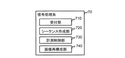
- the signal processing system 70 performs various data processing and display and storage of processing results, and includes a CPU 71, a storage device 72, an external storage device 73, a display device 74, and an input device 75.
- the signal processing system 70 of the present embodiment gives a control signal to the sequencer 40 according to, for example, an imaging sequence, and collects data for creating a tomographic image of the subject 10 from the receiving system 60. Then, a tomographic image of the subject 10 is reconstructed using the collected data.
- the imaging sequence is generated using imaging parameters input from the operator via the input device 75 based on a pulse sequence stored in advance in the storage device 72 or the like.
- the signal processing system 70 of the present embodiment includes a reception unit 710 that receives imaging parameters from an operator, and a gradient magnetic field of a pulse sequence that is held in advance using the received imaging parameters.
- a sequence creation unit 720 that determines the shape and creates an imaging sequence to be used for imaging, a measurement control unit 730 that performs measurement of echo signals according to the created imaging sequence, and places the measured echo signals in k-space, k
- An image reconstruction unit 740 for reconstructing an image from echo signals arranged in space.
- the display device 74 displays the reconstructed tomographic image and constitutes an interface for the operator to input various control information together with the input device 75.
- the input device 75 is composed of, for example, a trackball or mouse, a keyboard, and the like.
- the storage device 72 and the external storage device store information input by the operator, information in the middle of the processing of the signal processing system 70, information generated by the processing, and the like.
- the transmission coil 51 and the gradient magnetic field coil 31 are placed in a static magnetic field space of the static magnetic field generation system 20 into which the subject 10 is inserted, and face the subject 10 in the vertical magnetic field system, If the magnetic field method is used, it is installed so as to surround the subject 10.
- the receiving coil 61 is installed so as to face or surround the subject 10.
- the radionuclide to be imaged by the MRI apparatus is a hydrogen nucleus (proton) which is the main constituent material of the subject, as is widely used in clinical practice.
- proton the main constituent material of the subject
- the form or function of the human head, abdomen, limbs, etc. is imaged two-dimensionally or three-dimensionally.
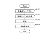
- FIG. 3 is a processing flow of the photographing process of the present embodiment.
- the imaging parameter input by the operator via the input device 75 is received by the receiving unit 710 (step S1101).
- the input imaging parameters include a frequency encoding number (sampling number in the frequency encoding direction) F and a phase encoding number (sampling number in the phase encoding direction) P.
- the sequence creation unit 720 determines a gradient magnetic field waveform using the imaging parameters, and creates an imaging sequence from a pulse sequence stored in advance in the storage device 72 or the like (step S1102).
- the measurement control unit 730 instructs the sequencer according to the imaging sequence, measures the echo signal, and fills the k space with data (step S1103).
- the image reconstruction unit 740 reconstructs an image by gridding the data filled in the k space onto the lattice points of the orthogonal coordinate system of the k space and performing a two-dimensional Fourier transform (step S1104).
- a fan-shaped blade is used instead of the rectangular blade used in the conventional hybrid radial method as the scanning area at the time of echo signal measurement in step S1103. Then, the k space is scanned with the plurality of fan blades. The scanning trajectory in each fan-shaped blade is determined so that the desired TE echo signal is arranged in the low spatial frequency region of the k space, and the shape thereof is set in a pendulum shape.
- the sequence creation unit 720 determines a gradient magnetic field waveform that realizes such measurement, and creates an imaging sequence.
- the measurement control unit 730 controls each unit according to the created imaging sequence, and executes the measurement.
- the details of the fan blade of the present embodiment and the imaging sequence creation processing by the sequence creation unit 720 for realizing the measurement will be described.
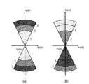
- FIG. 4A shows a conventional imaging sequence 210.
- FIG. 5A shows a rectangular region (rectangular blade) 310 on the k space measured by the imaging sequence 210 shown in FIG. 4A.
- the RF, Gx, and Gy axes indicate application timings of the RF pulse and the gradient magnetic field pulse in the biaxial direction, respectively.
- a plurality of refocus RF pulses 212 are applied during the time TR until the next excitation RF pulse 211 is applied, and each time a refocus RF pulse is applied. Acquire an echo signal. At this time, different phase encoding is given to each echo signal.
- the rectangular blade 310 is repeatedly changed while changing the angle (rotation angle ⁇ ) with the kx axis of the k space, and the entire k space is measured.
- the waveforms of the gradient magnetic field pulses 213 and 214 are determined so as to realize this.
- the number of repetitions B (B is a natural number) of measurement (one shot) of one rectangular blade 310 is set by the operator as an imaging parameter as described above.
- b (b is a natural number satisfying 1 ⁇ b ⁇ B)
- the rectangular blade (b-th rectangular blade) that is measured in the first iteration is 310 (b)
- the frequency encoding direction of this rectangular blade 310 (b) is
- the kx (b) axis and the phase encoding direction be the ky (b) axis.
- the angle formed by the x axis (kx axis) and the kx (b) axis in the k space is defined as the rotation angle ⁇ (b) of the rectangular blade 310 (b).
- sampling number F in the kx (b) axis direction and the sampling number P in the ky (b) axis direction for each rectangular blade 310 (b) are set by the operator as imaging parameters (frequency encoding number and phase encoding number), respectively. Is done.
- a fan blade (unit region) having the same area (same sampling number) as the rectangular blade 310 is measured as a unit measurement between FSE shots. Then, for each shot, the angle (rotation angle ⁇ ) formed by the fan-shaped blade with the kx axis is changed, and unit measurement is repeated to measure the entire k space with the radius R. Further, each fan blade 320 is measured so that an echo signal having a desired contrast is arranged in a low spatial frequency region of k-space.
- FIG. 4 (B) shows the imaging sequence 220 of the present embodiment for realizing this
- FIG. 5 (B) shows the fan blade 320 of the present embodiment.
- the fan-shaped blade 320 of the present embodiment is surrounded by an arc between two radii R and a radius R of a circle with a radius R centered at the origin of the k space, as shown in FIG. In the region, the central angle is ⁇ [rad].
- the ky (b) axis of the b-th fan blade 320 (b) is on a line (center line) that bisects the central angle ⁇ of the fan blade 320 (b).
- the kx (b) axis is a direction orthogonal to the ky (b) axis.
- the rotation angle ⁇ (b) of the fan blade 320 (b) is an angle formed by the kx (b) axis and the kx axis.
- the imaging sequence 220 of this embodiment is basically the same as the conventional FSE, and after applying one excitation RF pulse 211, the time until the next excitation RF pulse 211 is applied.
- a plurality of refocus RF pulses 212 are applied during TR, and an echo signal is acquired each time the refocus RF pulses are applied.
- the waveforms of the gradient magnetic field pulses 223 and 224 in the Gx-axis and Gy-axis directions are determined so that data is measured in the fan blade 320 with the following echo signal arrangement and scanning locus.
- the sequence creation unit 720 calculates and determines the radius R, the central angle ⁇ , and the total blade number B fan , which are blade parameters, using the imaging parameters (blade parameter determination processing; step S1201).
- the total number of blades B fan is the number of fan blades 320 necessary to measure the entire k space with the radius R once.
- the central angle ⁇ is determined as follows.
- the number of samples in each fan blade 320 (b) is the number of samples of the rectangular blade 310.
- FP is determined by the frequency encoding step number F and the phase encoding step number P set by the operator as imaging parameters.
- the area S of the fan-shaped blade 320 is the same as the area FP of the rectangular blade 310. Therefore, the area S of the fan-shaped blade 320 is expressed by the following equation (1) using the sampling number F and the sampling number P.
- the total blade number B fan of the fan-shaped blade 320 is expressed by the following formula (4).
- the sequence creation unit 720 divides the sector blade 320 in the radial direction according to the number of echo signals acquired in one shot, and determines the arrangement area of each echo signal in the sector blade 320 ( Step S1202).
- E echo signals are divided into E in the radial direction by dividing the sector blade 320 into E areas (divided areas) 321 (n) (n is a natural number satisfying 1 ⁇ n ⁇ E) ), Respectively.
- a divided area of each of the b-th fan blades 320 (b) is represented as 321 (b, n).
- control is performed so that an echo signal having a desired contrast is arranged in the low spatial frequency region of the k space, and the other echo signals are arranged in the high spatial frequency region. Therefore, control is performed so that an echo signal at a desired timing (effective TE) is arranged in the low spatial frequency region in the vicinity of the origin of the k space in the divided region 321.
- the order of echo signal arrangement for each divided region 321 (b, n) in the fan blade 320 (b) varies depending on the desired contrast.
- the divided region 321 (b, 1) where the first echo signal is arranged is the radius r (b, 1) of the sector blade 320 (b)
- the divided region where the nth echo signal is arranged 321 (b, n) is a region between the radius r (b, n) and the radius r (b, n-1) of the sector blade 320 (b).
- r (b, E) is the radius R (b) of the fan blade 320 (b).
- the radius r (b, n) is expressed by the following formula (6).
- the sequence creation unit 720 determines a scanning locus in each divided area 321n (step S1203).
- one echo signal becomes a linear locus (linear locus 510).
- a scanning locus is set in each divided region 321 (b, n) in the fan blade 320 (b).
- the scanning trajectory in each divided region 321 (b, n) is a series of trajectories, as shown in FIG. 9 (D), and the arcuate portion concentric with the arc of the fan-shaped blade 320 and two adjacent trajectories.
- a pendulum trajectory (pendulum trajectory 520) having alternating linear portions parallel to the radial direction connecting the arc-shaped portions.
- the pendulum locus 520 is composed of an arc portion (arc locus) 521 and a straight portion (straight locus) 522 that are alternately repeated M times (here, 3 times).
- the interval A (b, n) of the arc-shaped trajectory 521 which corresponds to the length of the linear trajectory 522, is the radius r (b, n) of the divided region 321 (b, n) of the sector blade 320 (b) and Using the switching number M (b, n), it is expressed by the following equation (7).
- the sampling length L (b, n) of the pendulum trajectory 520 in each divided area 321 (b, n) is the sum of the arc-shaped trajectory 521 and the linear trajectory 522 for the number of switching M (b, n). Therefore, it is expressed by the following formula (8).
- m is a natural number satisfying 1 ⁇ m ⁇ M.
- the total sampling length of the pendulum trajectory 520 in the fan blade 320 (b) is equal to the sampling number (sampling length) F in the frequency encoding direction of the rectangular blade 310 (b), so the fan blade 320 (b)
- the number M (b, n) of switching of the divided areas 321 (b, n) is expressed by Expression (9).
- the arc-shaped locus 521 at the time of switching m (natural number satisfying 1 ⁇ m ⁇ M) is expressed by the following equation (10). expressed. However, ⁇ / 2 ⁇ t ⁇ ⁇ / 2.
- a linear locus 522 at the m-th switching in the divided region 321 (b, n) of the sector blade 320 (b) is expressed by the following equation (11). However, (m ⁇ 1) A (n) ⁇ t ⁇ mA (n).
- the sequence creation unit 720 takes into account the rotation angle ⁇ (b) for each fan blade 320 (b), and the total number of blades B fan for each shot.
- the gradient magnetic field shape is determined (step S1204).
- sequence creation unit 720 first creates a rotation matrix Rot (b) shown in the following equation (12) using the rotation angle ⁇ (b) of each fan blade 320 (b).
- the above-described pendulum-shaped locus 520 is realized by adding a blip in the phase encoding direction while switching the frequency encoding direction during reading of one echo signal.
- the sequence creation unit 720 of the present embodiment uses the imaging parameters set by the operator, and the echo signal having a desired contrast is arranged in the low spatial frequency region of the k space within the fan blade 320.
- the gradient magnetic field waveform to be measured is determined.
- the measurement control unit 730 of this embodiment operates each unit in accordance with an instruction output from the signal processing system 70 in accordance with the imaging sequence having the gradient magnetic field waveform. That is, the measurement of rotating each fan blade 320 (b) from the kx axis by the rotation angle ⁇ (b) is repeated B fan times. At this time, in each fan blade 320 (b), control is performed so that an echo signal having a desired contrast is arranged in a low spatial frequency region of k-space. Then, the image reconstruction unit 740 of the present embodiment reconstructs an image by gridding k-space data obtained by the above measurement on lattice points of an orthogonal coordinate system and performing two-dimensional Fourier transform.
- artifacts can be reduced because of non-orthogonal measurement. Furthermore, only a signal having a desired contrast is arranged in a low spatial frequency region that determines contrast in the k space. The echo signals other than the effective TE are arranged outside the low spatial frequency region. Therefore, an image having a desired contrast can be obtained with high accuracy without mixing other contrast signals.
- Equation (4) when comparing Equation (4) and Equation (13), the number of blades required to scan the same k-space area (a perfect circular k-space with a radius R) is the fan blade 320. Compared to the case where the rectangular blade 310 is used, it is only half, and the measurement time can be shortened. Therefore, according to this embodiment, the filling efficiency of the k space is improved and the measurement time can be further shortened.
- the pulse sequence combined in the present embodiment may be a pulse sequence that acquires a plurality of echo signals between TRs after the application of one excitation pulse, and can be applied regardless of the sequence type and contrast.
- the centric arrangement shown in FIG. 8A has been described as an example, but the arrangement order of the echo signals is not limited to this.
- the echo signal at the desired TE (effective TE) is determined to be arranged in the divided region 321 closest to the origin of the k space. With this configuration, an image with a desired contrast can be obtained.
- an anticentric data arrangement may be used in which data is acquired in order from the outer periphery side.
- e (1 ⁇ e ⁇ E) of echo signals acquired between TRs.
- an echo shift may be applied.
- the divided regions and scanning trajectories are determined by the same method as described above, and are determined in consideration of the echo arrangement order when determining the gradient magnetic field shape of each shot in step S1204.
- FIG. 11 (A) shows the order of arrangement of echo signals before the echo shift
- FIG. 11 (B) shows the order of arrangement of echo signals after the echo shift.
- the case where the number E of echo signals is 3 is illustrated.
- the number given to the side of the fan-shaped blade 320 is the echo number.
- Multi-contrast measurement is a measurement technique that acquires two or more different contrast images simultaneously in one measurement. For example, it is realized by acquiring two or more echo signals in one pulse sequence and filling them in two or more k spaces.
- Multi-contrast measurement is often used for simultaneous acquisition of proton density weighted images (PDW) and T2 weighted images (T2W), both of which have a long TR. Since the PDW uses a short effective TE, the echo signal arrangement uses centric. Since T2W uses a relatively long TE, anticentric or echo shift is used. Note that the number of echo shifts when echo shift is used is automatically calculated according to the effective TE of T2W.
- the area inside the circle of radius k in the k space is measured over the entire area, but is not limited thereto.
- half measurement may be applied in which approximately 50% of the k space is measured and the remaining region is estimated and filled using the symmetry of the k space.
- the spatial resolution is not lowered, but the measurement time is shortened because the actual measurement area is small.
- FIG. 12 shows an example of an actual measurement area (scanning area) in k-space when half measurement is applied to this embodiment.
- Fig. 12 (A) is an example of semi-circular half measurement that measures the inside of a semi-circular region among the inner regions of a circle with radius R in k-space.
- the echo signal is measured only for the fan-shaped blade 320 included in the region of ky ⁇ 0 within the circle of radius R in the k space.
- FIG. 12B is an example of fan-type half measurement.
- fan-type half measurement echo signals are measured only for even-numbered or odd-numbered fan-shaped blades 320. However, when the total number of blades B fan calculated by Equation (4) is an odd number, the data measurement area and the estimated area do not correspond to each other, so 1 is added to B fan to make it an even number.
- this embodiment may be combined with measurement that scans within differently shaped blades.
- a base measurement as a reference is performed, and data of the entire inner region of a circle with a radius R in k space is acquired.
- the measurement by the concentric blades which are concentric circular regions divided by the concentric circumference centering on the origin of the k space is repeated every predetermined time.
- a plurality of concentric blades acquired at a time measure only the low spatial frequency region of k-space each time, and the high spatial frequency region is a partial region as shown by shading in FIG. Measure different areas each time. And the area
- k-space data in which only the low-frequency data of k-space is updated can be obtained every predetermined time.
- the measurement time can be shortened. For this reason, the number of repetitions can be increased within the same time, and the resolution in the time direction of dynamic measurement can be improved.
- the scanning area in the k space is an inner area of a circle centered on the origin, but in this embodiment, it is an inner area of an ellipse centered on the origin in the k space.
- the MRI apparatus of this embodiment is basically the same as that of the first embodiment. Also, each functional configuration realized by the signal processing system 70 is the same as that of the first embodiment, and the imaging processing by these functions is also the same. However, as described above, in this embodiment, since the inner region of the ellipse in the k space is measured, the shape of the gradient magnetic field of the imaging sequence for realizing it is different. Hereinafter, the present embodiment will be described focusing on the configuration different from the first embodiment.
- the elliptical k-space is measured by measurement with the fan-shaped blade 320.
- rectangular resolution measurement and / or rectangular visual field measurement that cannot be realized by conventional non-orthogonal measurement can be performed.
- FIG. 14 (A) shows a conventional circular k-space measurement for measuring a perfect circular k-space 610 with the same number of encodings in the kx direction and the ky direction.
- the rectangular resolution measurement is a measurement performed by changing the number of encodings in the kx direction and the ky direction, as shown in FIG. 14 (B), for this perfect circular k-space measurement.
- this is realized by zero-padded measurement using a zero-padded k-space 620.
- the spatial resolution in the x direction is different from the spatial resolution in the y direction.
- Rectangle visual field measurement is a method of changing the visual field between the kx direction and the ky direction to reduce the measurement time without reducing the spatial resolution.
- the zero-padded k-space 620 shown in FIG. 14 (B) is realized by enlarged pitch measurement using the enlarged pitch k-space 630 shown in FIG.
- the phase encoding direction field of view is reduced to reduce the measurement time without reducing the spatial resolution.
- R ′ aR ⁇ R, 0.0 ⁇ a ⁇ 1.0, a: ellipticity.
- An internal region (elliptical k-space) 640 is assumed.
- the total number B fan of the fan blades 320 necessary for filling the inner region of the elliptical k space 640 is obtained by the following equation (15).
- a perfect circular k space 650 having a radius ⁇ aR shown in FIG. 15A is considered as a perfect circular k space having the same area as the elliptical k space 640.
- a scanning trajectory filling the perfect circular k space 650 is obtained by the equations (6) to (12) of the first embodiment.
- the trajectory for scanning the outer region S1 among the scanning trajectories obtained in the perfect circular k space 650 becomes unnecessary.
- the ellipse is outside the perfect circle, and therefore the inner region S2 cannot be filled only with the scanning locus obtained in the perfect circular k space 650. Therefore, in this embodiment, by assigning the scanning trajectory of the outer region S1 of the fan-shaped blade 320 including the outer region S1 to the scanning of the inner region S2 of the fan-shaped blade 320 including the inner region S2, excess or deficiency of the trajectory is achieved. lose.
- a transformation matrix is created from the geometric relationship between the outer region S1 and the inner region S2, and is applied to the locus of the outer region S1, thereby obtaining the locus of the inner region S2.
- the transformation matrix T is used to represent the following region (16).
- the vectors p 1 and p 2 are expressed by Expression (18) and Expression (19), respectively.
- the vectors q and r indicate the inner and outer boundaries of the outer region S1 and the inner region S2, respectively.
- the vectors x and y are unit vectors parallel to the kx axis and the ky axis, respectively.
- the sequence creation unit 720 of the present embodiment uses this transformation matrix T to determine the gradient magnetic field waveform so as to scan the corresponding internal region S2 when measuring the fan blade 320 including the external region S1.
- the rectangular visual field measurement is realized by expanding the zero-padded k-space 620 (elliptical k-space 640) in the ky direction as shown in FIG. 15 (C).
- the measurement control unit 730 performs measurement according to a sequence created by the rectangular resolution measurement method.
- the image reconstruction unit 740 expands the obtained k-space (zero-padded k-space 620 (elliptical k-space 640)) in the ky direction (post-enlargement k-space 660), performs gridding processing, and reconstructs the image.
- the pitch ⁇ ky in the ky direction becomes a k-space (k space 660 after expansion) that is 1 / a times (> 1.0) the kx direction. Since there is a relationship shown in Equation (20) between the k-space pitch and the imaging field of view (FOV), a rectangular imaging field that is short in the y direction can be obtained by using the enlarged k-space (enlarged k-space 660). become.
- the elliptical k-space is measured using a fan-shaped blade as in the first embodiment.
- the echo arrangement order is not limited as long as an echo signal of a desired TE (effective TE) can be arranged in a low spatial frequency region of k-space, such as centric, anticentric, echo shift. Any of these may be used. Further, multi-contrast measurement may be applied. Further, half measurement may be applied. Moreover, you may combine with the blade of a different shape.
- the signal processing system 70 of the MRI apparatus 100 is configured to calculate a gradient magnetic field waveform that realizes k-space scanning with a fan-shaped blade from imaging conditions, but is not limited thereto.
- the gradient magnetic field waveform may be calculated on an information processing apparatus that can transmit and receive data to and from the MRI apparatus 100 and is independent of the MRI apparatus.
- the sequence creation unit 720 calculates the fan blade parameters using the imaging parameters and calculates the gradient magnetic field shape every time the imaging parameters are set during imaging.
- a gradient magnetic field shape may be calculated in advance for each imaging parameter that may be used, and stored as a database in the storage device 72 or the like in association with the imaging parameter.
- the sequence creation unit 720 refers to the database, extracts the gradient magnetic field shape stored in association with the received imaging parameter, and creates an imaging sequence. .
- the unit area is a fan-shaped area surrounded by an arc between two radii R and a radius R of a circle with a radius R centered on the origin of the k space. It is not limited to this. It may be an area surrounded by two line segments starting from the origin of the k space and a line connecting the other end points of the two line segments.
- the unit area is divided into a plurality of divided areas having different positions in the radial direction, and the measurement control unit acquires a plurality of data for each of the plurality of divided areas.
- the measurement control unit acquires each data of the miracle in the circumferential direction while sequentially changing the radial position in the divided region.
- the measurement control unit may acquire each data of the miracle in the direction orthogonal to the radial direction while sequentially changing the radial position in the divided region.
- the trajectory in the circumferential direction or the trajectory in the direction orthogonal to the radial direction may or may not have a portion (a portion for continuously acquiring data) connected between adjacent trajectories.
Abstract
Description
以下、本発明を適用する第一の実施形態について説明する。以下、本発明の実施形態を説明するための全図において、同一機能を有するものは同一符号を付し、その繰り返しの説明は省略する。 << First Embodiment >>
Hereinafter, a first embodiment to which the present invention is applied will be described. Hereinafter, in all the drawings for explaining the embodiments of the present invention, those having the same function are denoted by the same reference numerals, and repeated explanation thereof is omitted.
本実施形態では、1ショット毎に、従来の長方形ブレード310の代わりに、扇型のブレード320内を計測するため、各扇型ブレード320(b)内のサンプリング数は、長方形ブレード310のサンプリング数同様、操作者が撮像パラメータとして設定する周波数エンコードステップ数Fと位相エンコードステップ数Pとにより定まり、FPである。 Next, the central angle φ is determined as follows.
In this embodiment, since the inside of the fan-shaped


しかし、本実施形態は、1ショット毎のエコー信号の走査領域を扇型ブレードとし、走査順、走査軌跡を上述のように決定したことにより、上記効果を得るものである。従って、本実施形態で組み合わせるパルスシーケンスは、1回の励起パルスの印加後、TR間に複数のエコー信号を取得するパルスシーケンスであればよく、シーケンス種やコントラストによらず適用可能である。 In the present embodiment, the case of combining with the FSE sequence has been described as an example.
However, in the present embodiment, the above effect is obtained by setting the scanning area of the echo signal for each shot as a fan-shaped blade and determining the scanning order and the scanning locus as described above. Therefore, the pulse sequence combined in the present embodiment may be a pulse sequence that acquires a plurality of echo signals between TRs after the application of one excitation pulse, and can be applied regardless of the sequence type and contrast.
次に、本発明を適用する第二の実施形態を説明する。第一の実施形態では、k空間の走査領域が、原点を中心とする円の内部領域であるが、本実施形態では、k空間の原点を中心とする楕円の内部領域とする。 << Second Embodiment >>
Next, a second embodiment to which the present invention is applied will be described. In the first embodiment, the scanning area in the k space is an inner area of a circle centered on the origin, but in this embodiment, it is an inner area of an ellipse centered on the origin in the k space.


Claims (15)
- 静磁場を発生する静磁場発生手段と、前記静磁場中に配置された被検体の所望の撮像領域に傾斜磁場と高周波磁場を印加する磁場印加手段と、前記所望の撮像領域からのエコー信号を検出する検出手段と、前記磁場印加手段と前記検出手段と制御して、k空間内の所定の領域のデータを取得するよう前記エコー信号を計測する計測制御手段と、前記k空間のデータを用いて前記撮像領域の画像を再構成する画像再構成手段と、を備える磁気共鳴イメージング装置であって、
前記計測制御手段は、1TR内に単位領域の複数のデータを取得する単位計測を、前記単位領域を前記k空間の原点を中心に予め定めた回転角だけ当該単位計測毎に回転させて繰り返すよう制御を行い、
前記単位計測では、所望のコントラストのエコー信号を前記k空間の低空間周波数領域に配置し、
前記単位領域は、前記k空間の原点を始点とする2本の線分と当該2本の線分の他の端点を結ぶ線とによって囲まれた領域であること
を特徴とする磁気共鳴イメージング装置。 A static magnetic field generating means for generating a static magnetic field, a magnetic field applying means for applying a gradient magnetic field and a high-frequency magnetic field to a desired imaging area of a subject arranged in the static magnetic field, and an echo signal from the desired imaging area Using detection means for detecting, measurement control means for measuring the echo signal so as to acquire data of a predetermined region in k space, controlled by the magnetic field applying means and the detection means, and using the data in the k space An image reconstruction means for reconstructing an image of the imaging region, and a magnetic resonance imaging apparatus comprising:
The measurement control unit repeats unit measurement for acquiring a plurality of data of unit areas in 1TR by rotating the unit area by a predetermined rotation angle around the origin of the k space for each unit measurement. Control
In the unit measurement, an echo signal having a desired contrast is arranged in the low spatial frequency region of the k space,
The unit region is a region surrounded by two line segments starting from the origin of the k space and a line connecting the other end points of the two line segments. . - 請求項1記載の磁気共鳴イメージング装置であって、
前記2本の線分は、それぞれ、前記k空間の原点を中心とする円の半径であり、
前記端点を結ぶ線は、前記円の弧であること
を特徴とする磁気共鳴イメージング装置。 The magnetic resonance imaging apparatus according to claim 1,
Each of the two line segments is a radius of a circle centered on the origin of the k space,
The line connecting the end points is an arc of the circle. - 請求項2項記載の磁気共鳴イメージング装置であって、
操作者から撮像条件を受け付ける撮像条件受付手段と、
受け付けた前記撮像条件から、撮像シーケンスを生成する撮像シーケンス生成手段と、を備え、
前記計測制御手段は、前記撮像シーケンスに従って、前記制御を行い、
前記撮像シーケンス生成手段は、
前記k空間の原点を中心とする円の半径、前記2本の線分が成す角度である中心角、および、それぞれ前記回転角が異なる単位領域の数である総単位領域数を決定するパラメータ決定手段と、
前記単位計測毎の、各エコー信号の配置領域を決定する領域決定手段と、
決定した前記各配置領域内の走査軌跡を決定する走査軌跡決定手段と、
前記単位領域毎の回転角に応じて、前記単位計測毎の走査軌跡を決定し、前記撮像シーケンスの傾斜磁場波形を決定する波形決定手段と、を備えること
を特徴とする磁気共鳴イメージング装置。 The magnetic resonance imaging apparatus according to claim 2,
Imaging condition receiving means for receiving imaging conditions from an operator;
Imaging sequence generation means for generating an imaging sequence from the received imaging conditions,
The measurement control means performs the control according to the imaging sequence,
The imaging sequence generation means includes
Parameter determination for determining the radius of a circle centered at the origin of the k-space, the central angle that is the angle formed by the two line segments, and the total number of unit regions that are the number of unit regions that each have a different rotation angle Means,
Area determining means for determining the arrangement area of each echo signal for each unit measurement;
Scanning trajectory determining means for determining a scanning trajectory in each determined arrangement area;
A magnetic resonance imaging apparatus comprising: waveform determining means for determining a scanning locus for each unit measurement according to a rotation angle for each unit region and determining a gradient magnetic field waveform of the imaging sequence. - 請求項3記載の磁気共鳴イメージング装置であって、
前記k空間の原点を中心とする円の半径は、周波数エンコード数により定まり、
前記中心角は、前記円の直径と当該単位領域内の総データ数とにより定まり、
前記総単位領域数は、2πを前記中心角で除算した値以上であること
を特徴とする磁気共鳴イメージング装置。 The magnetic resonance imaging apparatus according to claim 3,
The radius of the circle centered on the origin of the k space is determined by the frequency encoding number,
The central angle is determined by the diameter of the circle and the total number of data in the unit area,
The total number of unit regions is equal to or greater than a value obtained by dividing 2π by the central angle. - 請求項2記載の磁気共鳴イメージング装置であって、
前記各単位領域の回転角は、前記単位領域が、前記k空間の原点を中心とする円の周方向に重複なく配置されるよう決定されること
を特徴とする磁気共鳴イメージング装置。 The magnetic resonance imaging apparatus according to claim 2,
The rotation angle of each unit region is determined so that the unit regions are arranged without overlapping in the circumferential direction of a circle centered on the origin of the k space. - 請求項2記載の磁気共鳴イメージング装置であって、
前記各単位領域の回転角は、前記単位領域が、前記k空間の原点を中心とする円の半分の面積の領域に配置されるよう決定されること
を特徴とする磁気共鳴イメージング装置。 The magnetic resonance imaging apparatus according to claim 2,
The rotation angle of each unit region is determined so that the unit region is arranged in a region having a half area of a circle centering on the origin of the k space. - 請求項3記載の磁気共鳴イメージング装置であって、
前記各配置領域内の走査軌跡は、振り子状であること
を特徴とする磁気共鳴イメージング装置。 The magnetic resonance imaging apparatus according to claim 3,
The magnetic resonance imaging apparatus according to claim 1, wherein the scanning trajectory in each of the arrangement regions has a pendulum shape. - 請求項5記載の磁気共鳴イメージング装置であって、
前記計測制御手段は、前記単位計測において、当該単位計測の対象である単位領域が、前記円の半径が楕円率の平方根倍となる楕円の内部領域外であって、前記円の内部領域内である領域を含む場合、当該領域の走査の代わりに、他の単位領域の、前記円の内部領域外であって前記楕円の外部領域内の同面積の領域のデータを取得するよう制御すること
を特徴とする磁気共鳴イメージング装置。 The magnetic resonance imaging apparatus according to claim 5,
In the unit measurement, the measurement control unit is configured such that a unit region that is a target of the unit measurement is outside the inner region of the ellipse in which the radius of the circle is a square root of the ellipticity, and within the inner region of the circle. When a certain area is included, instead of scanning the area, control is performed so as to acquire data of an area of the same area outside the inner area of the circle and outside the ellipse of another unit area. A magnetic resonance imaging apparatus. - 請求項3記載の磁気共鳴イメージング装置であって、
前記領域決定手段は、各エコー信号を、セントリック、アンチセントリックおよびエコーシフトのいずれかで配置すること
を特徴とする磁気共鳴イメージング装置。 The magnetic resonance imaging apparatus according to claim 3,
The magnetic resonance imaging apparatus characterized in that the region determining means arranges each echo signal in one of centric, anticentric, and echo shift. - 請求項3記載の磁気共鳴イメージング装置であって、
前記波形決定手段は、前記単位計測毎の走査軌跡を決定後、k空間の軸方向に当該k空間全体を所定量延伸後、前記傾斜磁場波形を決定すること
を特徴とする磁気共鳴イメージング装置。 The magnetic resonance imaging apparatus according to claim 3,
The waveform determination means determines the gradient magnetic field waveform after determining a scanning trajectory for each unit measurement and then extending the entire k space by a predetermined amount in the axial direction of the k space. - 請求項1記載の磁気共鳴イメージング装置であって、
前記単位領域を径方向に位置の異なる複数個の分割領域に分割したことを特徴とする磁気共鳴イメージング装置。 The magnetic resonance imaging apparatus according to claim 1,
2. The magnetic resonance imaging apparatus according to claim 1, wherein the unit area is divided into a plurality of divided areas having different positions in the radial direction. - 請求項1記載の磁気共鳴イメージング装置であって、
前記単位領域を径方向に位置の異なる複数個の分割領域に分割し、前記計測制御手段は、前記複数の分割領域毎に前記複数のデータを取得することを特徴とする磁気共鳴イメージング装置。 The magnetic resonance imaging apparatus according to claim 1,
The unit region is divided into a plurality of divided regions having different positions in the radial direction, and the measurement control unit acquires the plurality of data for each of the plurality of divided regions. - 請求項12記載の磁気共鳴イメージング装置であって、
前記計測制御手段は、前記分割領域内において、周方向の奇跡を、その径方向の位置を順々に変更させながら、各データを取得することを特徴とする磁気共鳴イメージング装置。 The magnetic resonance imaging apparatus according to claim 12,
The magnetic resonance imaging apparatus characterized in that the measurement control means acquires each data of a miracle in the circumferential direction while sequentially changing its radial position in the divided region. - 請求項12記載の磁気共鳴イメージング装置であって、
前記計測制御手段は、前記分割領域内において、径方向に直交する方向の奇跡を、その径方向の位置を順々に変更させながら、各データを取得することを特徴とする磁気共鳴イメージング装置。 The magnetic resonance imaging apparatus according to claim 12,
The magnetic resonance imaging apparatus characterized in that the measurement control means acquires each data of a miracle in a direction orthogonal to the radial direction while sequentially changing the radial position in the divided region. - 磁気共鳴撮像装置におけるエコー信号計測方法であって、
k空間の原点を始点とする2本の線分と当該2本の線分の他の端点を結ぶ線とによって囲まれた単位領域のデータを単位データとして取得する単位計測ステップと、
前記単位計測ステップを、前記原点を中心に予め定めた回転角だけ前記単位領域を回転させて繰り返す繰返計測ステップと、を備えること
を特徴とするエコー信号計測方法。 An echo signal measurement method in a magnetic resonance imaging apparatus,
a unit measurement step for obtaining data of a unit area surrounded by two line segments starting from the origin of k-space and a line connecting the other end points of the two line segments as unit data;
An echo signal measurement method comprising: a step of repeating the unit measurement step by repeating the unit region by rotating the unit region by a predetermined rotation angle around the origin.
Priority Applications (2)
| Application Number | Priority Date | Filing Date | Title |
|---|---|---|---|
| US14/113,486 US9594142B2 (en) | 2011-05-20 | 2012-05-09 | Magnetic resonance imaging apparatus and echo signal measurement method |
| JP2013516279A JP5978430B2 (en) | 2011-05-20 | 2012-05-09 | Magnetic resonance imaging apparatus and echo signal measurement method |
Applications Claiming Priority (2)
| Application Number | Priority Date | Filing Date | Title |
|---|---|---|---|
| JP2011-113890 | 2011-05-20 | ||
| JP2011113890 | 2011-05-20 |
Publications (1)
| Publication Number | Publication Date |
|---|---|
| WO2012160970A1 true WO2012160970A1 (en) | 2012-11-29 |
Family
ID=47217051
Family Applications (1)
| Application Number | Title | Priority Date | Filing Date |
|---|---|---|---|
| PCT/JP2012/061837 WO2012160970A1 (en) | 2011-05-20 | 2012-05-09 | Magnetic resonance imaging device and echo signal measurement method |
Country Status (3)
| Country | Link |
|---|---|
| US (1) | US9594142B2 (en) |
| JP (1) | JP5978430B2 (en) |
| WO (1) | WO2012160970A1 (en) |
Cited By (1)
| Publication number | Priority date | Publication date | Assignee | Title |
|---|---|---|---|---|
| CN106842084A (en) * | 2016-12-30 | 2017-06-13 | 上海联影医疗科技有限公司 | A kind of MR imaging method and device |
Families Citing this family (3)
| Publication number | Priority date | Publication date | Assignee | Title |
|---|---|---|---|---|
| WO2015033779A1 (en) * | 2013-09-03 | 2015-03-12 | 株式会社 日立メディコ | Magnetic resonance imaging apparatus and magnetic resonance imaging method |
| CN109949307B (en) * | 2019-02-27 | 2024-01-12 | 昆明理工大学 | Image segmentation method based on principal component analysis |
| CN112379372A (en) * | 2020-11-27 | 2021-02-19 | 杭州睿影科技有限公司 | Millimeter wave holographic imaging method and device and security inspection system |
Citations (4)
| Publication number | Priority date | Publication date | Assignee | Title |
|---|---|---|---|---|
| JP2001112734A (en) * | 1999-10-18 | 2001-04-24 | Ge Yokogawa Medical Systems Ltd | Mri apparatus |
| JP2006025845A (en) * | 2004-07-12 | 2006-02-02 | Hitachi Medical Corp | Magnetic resonance imaging apparatus |
| JP2008529642A (en) * | 2005-02-11 | 2008-08-07 | コーニンクレッカ フィリップス エレクトロニクス エヌ ヴィ | Magnetic resonance imaging with adjustment of magnetic resonance attenuation |
| JP2010162332A (en) * | 2008-12-16 | 2010-07-29 | Toshiba Corp | Magnetic-resonance imaging diagnosis apparatus and magnetic-resonance imaging method |
Family Cites Families (3)
| Publication number | Priority date | Publication date | Assignee | Title |
|---|---|---|---|---|
| US7285955B2 (en) * | 2005-04-21 | 2007-10-23 | University Health Network | System and method for improved data acquisition for medical imaging |
| WO2008111416A1 (en) * | 2007-03-09 | 2008-09-18 | Hitachi Medical Corporation | Magnetic resonance imaging apparatus and magnetic resonance imaging method |
| US9513356B2 (en) * | 2011-05-20 | 2016-12-06 | Hitachi, Ltd. | Magnetic resonance imaging apparatus and reconstructed image acquisition method |
-
2012
- 2012-05-09 WO PCT/JP2012/061837 patent/WO2012160970A1/en active Application Filing
- 2012-05-09 US US14/113,486 patent/US9594142B2/en active Active
- 2012-05-09 JP JP2013516279A patent/JP5978430B2/en active Active
Patent Citations (4)
| Publication number | Priority date | Publication date | Assignee | Title |
|---|---|---|---|---|
| JP2001112734A (en) * | 1999-10-18 | 2001-04-24 | Ge Yokogawa Medical Systems Ltd | Mri apparatus |
| JP2006025845A (en) * | 2004-07-12 | 2006-02-02 | Hitachi Medical Corp | Magnetic resonance imaging apparatus |
| JP2008529642A (en) * | 2005-02-11 | 2008-08-07 | コーニンクレッカ フィリップス エレクトロニクス エヌ ヴィ | Magnetic resonance imaging with adjustment of magnetic resonance attenuation |
| JP2010162332A (en) * | 2008-12-16 | 2010-07-29 | Toshiba Corp | Magnetic-resonance imaging diagnosis apparatus and magnetic-resonance imaging method |
Non-Patent Citations (2)
| Title |
|---|
| M.S.SUSSMAN ET AL.: "SPIRAL-PR: A NEW POLAR K-SPACE TRAJECTORY FOR FLEXIBLE VARIABLE-DENSITY SAMPLING", PROC. INTL. SOC. MAG. RESON. MED., 7 May 2005 (2005-05-07), pages P902 * |
| M.SARANATHAN ET AL.: "Coronary artery imaging at 3T using a novel ECG gated SSFP-Dixon sequence and a motion insensitive view ordering scheme", PROC. INTL. SOC. MAG. RESON. MED., 18 April 2009 (2009-04-18), pages P3818 * |
Cited By (1)
| Publication number | Priority date | Publication date | Assignee | Title |
|---|---|---|---|---|
| CN106842084A (en) * | 2016-12-30 | 2017-06-13 | 上海联影医疗科技有限公司 | A kind of MR imaging method and device |
Also Published As
| Publication number | Publication date |
|---|---|
| US20140055137A1 (en) | 2014-02-27 |
| US9594142B2 (en) | 2017-03-14 |
| JPWO2012160970A1 (en) | 2014-07-31 |
| JP5978430B2 (en) | 2016-08-24 |
Similar Documents
| Publication | Publication Date | Title |
|---|---|---|
| US8344729B2 (en) | Magnetic resonance imaging apparatus | |
| JP5399240B2 (en) | Magnetic resonance imaging apparatus and method for correcting error caused by gradient magnetic field | |
| JP5221570B2 (en) | Magnetic resonance imaging apparatus and multi-contrast image acquisition method | |
| JP6117097B2 (en) | Magnetic resonance imaging apparatus and reconstructed image acquisition method | |
| JP5942268B2 (en) | Magnetic resonance imaging apparatus and magnetic resonance imaging method | |
| JP6464088B2 (en) | Magnetic resonance imaging apparatus and magnetic resonance imaging method | |
| WO2010116772A1 (en) | Magnetic resonance imaging device | |
| JP5227338B2 (en) | Magnetic resonance imaging apparatus and magnetic resonance imaging method | |
| US20120112745A1 (en) | Magnetic resonance imaging apparatus and magnetic resonance imaging method | |
| JP5978430B2 (en) | Magnetic resonance imaging apparatus and echo signal measurement method | |
| JP5770191B2 (en) | Magnetic resonance imaging apparatus and multi-echo multi-contrast imaging method | |
| JP5564213B2 (en) | Magnetic resonance imaging system | |
| JP4707558B2 (en) | Magnetic resonance imaging system | |
| JP2008307303A (en) | Magnetic resonance imaging system | |
| JP5637694B2 (en) | Magnetic resonance imaging apparatus and non-orthogonal coordinate system scanning method | |
| JP2007275481A (en) | Magnetic resonance imaging device | |
| JP6013324B2 (en) | Magnetic resonance imaging apparatus and radial sampling method | |
| JP2016131847A (en) | Magnetic resonance imaging apparatus and magnetic resonance imaging method |
Legal Events
| Date | Code | Title | Description |
|---|---|---|---|
| 121 | Ep: the epo has been informed by wipo that ep was designated in this application |
Ref document number: 12789761 Country of ref document: EP Kind code of ref document: A1 |
|
| ENP | Entry into the national phase |
Ref document number: 2013516279 Country of ref document: JP Kind code of ref document: A |
|
| WWE | Wipo information: entry into national phase |
Ref document number: 14113486 Country of ref document: US |
|
| NENP | Non-entry into the national phase |
Ref country code: DE |
|
| 122 | Ep: pct application non-entry in european phase |
Ref document number: 12789761 Country of ref document: EP Kind code of ref document: A1 |