WO2012159900A1 - Sealing plate - Google Patents
Sealing plate Download PDFInfo
- Publication number
- WO2012159900A1 WO2012159900A1 PCT/EP2012/058737 EP2012058737W WO2012159900A1 WO 2012159900 A1 WO2012159900 A1 WO 2012159900A1 EP 2012058737 W EP2012058737 W EP 2012058737W WO 2012159900 A1 WO2012159900 A1 WO 2012159900A1
- Authority
- WO
- WIPO (PCT)
- Prior art keywords
- sealing plate
- membrane
- plate according
- thickness
- workpiece
- Prior art date
Links
Images


Classifications
-
- B—PERFORMING OPERATIONS; TRANSPORTING
- B25—HAND TOOLS; PORTABLE POWER-DRIVEN TOOLS; MANIPULATORS
- B25B—TOOLS OR BENCH DEVICES NOT OTHERWISE PROVIDED FOR, FOR FASTENING, CONNECTING, DISENGAGING OR HOLDING
- B25B11/00—Work holders not covered by any preceding group in the subclass, e.g. magnetic work holders, vacuum work holders
- B25B11/005—Vacuum work holders
Definitions
- the invention relates to a sealing plate for a vacuum block for fixing workpieces on a Fixierbalken or fixing table using negative pressure, wherein the sealing plate is clamped on at least one contact surface of the block suction and has at its periphery a sealing lip.
- Vacuum blocks are generally known in tensioning systems and are typically used to make plate-like workpieces, e.g. Wood panels or the like to clamp on a processing machine.
- This processing machine has a fixing table or more Fixierbalken on which usually sit a plurality of vacuum blocks and this rests on the workpiece to be machined.
- the vacuum block is clamped by means of vacuum or mechanically on the fixing table or on the fixing beam, wherein the workpiece to be machined is in turn held by means of negative pressure on the block suction.
- the vacuum blocks each have a sealing plate, which has on its circumference a voltage applied to the workpiece sealing lip.
- Such sealing plates are e.g. known from DE 202 06 489 U1 and DE 202 06 490 U1.
- the invention is therefore based on the object to provide a sealing plate, which is also applicable to vacuum blocks with Tastventilen.
- sealing plate of the type mentioned in the present invention that it is provided with a membrane and the membrane allows air to flow through.
- the sealing plate according to the invention has the significant advantage that it can be traversed by air and retained on the membrane processing residues.
- the suction block can be equipped with Tastventilen so that it is detected whether a workpiece rests or not.
- the feeler valve is opened, and when the vacuums are empty, the feeler valve remains closed. Vacuum blocks that are not occupied, so no longer have to be removed.
- the membrane is located on the sensing valve, which is operated via the membrane.
- the membrane has a smaller thickness than the sealing plate.
- the thickness of the membrane is 90% to 50%, in particular 85% to 60%, preferably 80% to 70% less than the thickness of the sealing plate. In one embodiment, the thickness of the membrane is 30% of the thickness of the seal plate.
- a preferred embodiment of the invention provides that the membrane has a joint at its edge.
- This joint has a smaller thickness than the thickness of the membrane.
- the joint is advantageous e.g. formed as a film hinge, wherein the film hinge may also have a waveform.
- the membrane has openings, e.g. slit-shaped or round, in particular circular openings on.
- the air is sucked through the openings and the membrane has the function of a filter.
- the axis of the opening is orthogonal to the surface of the sealing plate.
- the membrane is designed so elastic that it can be bulged out of the plane of the sealing plate when the plunger of the feeler valve rests against the underside thereof.
- the touch valve is not hindered by the adjacent membrane.
- the membrane is made of the same material as the rest of the sealing plate.
- the membrane is almost cost neutral directly introduced into the suction plate.
- the sealing plate consists of a two-component material, wherein the membrane is formed by the more elastic material. This has rubber-elastic properties and is preferably made of an elastomer.
- the top of the diaphragm is flush with the top of the seal plate or the workpiece seating surface when the workpiece rests.
- the plunger is thus shorter in the thickness of the membrane than conventional plungers.
- the plunger may be mushroom-shaped at its upper side, so that the membrane is not damaged by the plunger, in particular pierced.
- the upper side of the membrane is only partially provided with openings, wherein the sections or the areas lying between the sections are formed as information carriers.
- the information can be hints for the use of the block vacuum or the sealing plate. You can, however, e.g. also a logo or the manufacturer included.
- Figure 1 is a perspective view of a block suction with attached sealing plate according to the prior art
- Figure 2 is a section II - II according to Figure 2 without attached workpiece;
- FIG. 3 shows the section II - II according to Figure 2 with attached workpiece
- Figure 4 is a perspective view of the block suction with attached sealing plate according to the invention.
- FIG. 5 shows a section V - V according to FIG. 4 without a mounted workpiece
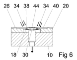
- FIG. 6 shows the section V - V according to Figure 4 with attached workpiece
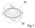
- Figure 7 is an enlarged view of the section VII of Figure 4.
- Figure 8 is an enlarged view of the membrane with a logo.
- FIG. 1 shows a perspective view of a total of 10 designated block suction, which is placed on a fixing bar 12 only hinted. Against lateral slippage of the suction block 10 is held by aprons, not shown, whereas the suction block 10 in the direction of the double arrow 16 on the fixing bar 12 is displaceable.
- the suction block 10 has on its suction side 18 on a sealing plate 20 which has a sealing lip 22 on its side facing the workpiece (not shown).
- the sealing lip 22 defines a suction space 24, to which for holding the workpiece negative pressure is applied.
- the sealing plate 20 has a central opening 32 which is penetrated by the plunger 30 of the Tastventils 28.
- the sensing valve 28 serves to detect a resting on the sealing plate 20 workpiece. If, as shown in FIG. 2, there is no workpiece on the sealing plate 20, the sensing valve 28 closes and no air is sucked out of the suction space 24. When resting on the sealing plate 20 workpiece, as shown in Figure 3, the plunger 30 is pressed and the sensing valve 28 is opened. The air is sucked out of the suction space (as shown by the arrows 34) and thereby sucked the workpiece to the seal plate 20. With the suction of the air, however, dirt or dust can be sucked, which can cause problems in the sensing valve 28 or in subsequent components.
- the sealing plate 20 has no opening for the plunger 30, but according to the invention is provided with a membrane 36.
- this membrane 36 has a plurality of small openings 38, which are preferably arranged in an annular area around the center of the membrane 36.
- the material and / or the thickness of the membrane 36 are chosen so that it is elastically deformable with little force.
- the plunger 30 engages and pushes the membrane, as shown in Figure 5, on the defined by the support elements 26 support plane 40.
- the membrane 36 is thus clearly visible. If a workpiece is placed on the sealing plate 20, then the plunger 30 is pressed together with the membrane 36 to the support plane 40, which is shown in Figure 6.
- the air can, as shown by the arrows 34, flow from the suction chamber 24 through the membrane 36 into the sensing valve 28, wherein dirt is retained.
- the membrane 36 is connected via a hinge 42 to the rest of the sealing plate 20, wherein the joint 42 is formed by a corrugated film hinge, which allows a spatial movement of the membrane 36. It can also be seen in FIGS. 5 and 6 that the tip of the plunger 30 is formed by a mushroom head 44 so that the membrane 36 is not damaged by the plunger 30.
- the thickness d of the membrane 36 is only a fraction of the thickness D of the sealing plate 20, whereby the elasticity of the membrane 36 is substantially increased.
- FIG 8 shows an enlarged view of the membrane 36, wherein the openings 38 are provided only in two sections 46. These sections 46 may have the shape of a logo.
- the area 48 located between the sections 46 is formed as an information carrier 50 and carries information for the use of the device or e.g. the name of the manufacturer.
Landscapes
- Engineering & Computer Science (AREA)
- Mechanical Engineering (AREA)
- Manipulator (AREA)
- Reciprocating Pumps (AREA)
Abstract
The invention relates to a sealing plate for a suction block for fixing workpieces to a fixing beam or fixing table using negative pressure, wherein the sealing plate is mounted on at least one abutment surface of the suction block and has a sealing lip at its periphery, wherein the sealing plate is provided with a diaphragm and the diaphragm allows air to flow through.
Description
Die Erfindung betrifft eine Dichtungsplatte für einen Blocksauger zum Fixieren von Werkstücken auf einem Fixierbalken oder Fixiertisch unter Verwendung von Unterdruck, wobei die Dichtungsplatte auf wenigstens eine Anlagefläche des Blocksaugers aufgespannt ist und an ihrem Umfang eine Dichtlippe aufweist.The invention relates to a sealing plate for a vacuum block for fixing workpieces on a Fixierbalken or fixing table using negative pressure, wherein the sealing plate is clamped on at least one contact surface of the block suction and has at its periphery a sealing lip.
Blocksauger sind allgemein bei Spannsystemen bekannt und werden in der Regel dazu verwendet, um plattenartige Werkstücke, z.B. Holzplatten oder dergleichen, an einer Bearbeitungsmaschine zu spannen. Diese Bearbeitungsmaschine weist einen Fixiertisch oder mehrere Fixierbalken auf, auf denen in der Regel mehrere Blocksauger aufsitzen und auf diesen das zu bearbeitende Werkstück aufliegt. Dabei wird der Blocksauger mittels Unterdruck oder mechanisch am Fixiertisch oder an den Fixierbalken gespannt, wobei das zu bearbeitende Werkstück seinerseits mittels Unterdruck am Blocksauger festgehalten wird. Um das Werkstück mit möglichst geringem Leckluftstrom halten zu können und um es gegen Verrutschen zu sichern, besitzen die Blocksauger jeweils eine Dichtungsplatte, die an ihrem Umfang eine am Werkstück anliegende Dichtlippe aufweist. Derartige Dichtungsplatten sind z.B. aus der DE 202 06 489 U1 und der DE 202 06 490 U1 bekannt.Vacuum blocks are generally known in tensioning systems and are typically used to make plate-like workpieces, e.g. Wood panels or the like to clamp on a processing machine. This processing machine has a fixing table or more Fixierbalken on which usually sit a plurality of vacuum blocks and this rests on the workpiece to be machined. Here, the vacuum block is clamped by means of vacuum or mechanically on the fixing table or on the fixing beam, wherein the workpiece to be machined is in turn held by means of negative pressure on the block suction. In order to hold the workpiece with the least possible leakage air flow and to secure it against slipping, the vacuum blocks each have a sealing plate, which has on its circumference a voltage applied to the workpiece sealing lip. Such sealing plates are e.g. known from DE 202 06 489 U1 and DE 202 06 490 U1.
Bei vielen Spannsystemen werden Blocksauger mit Tastventilen eingesetzt, um die Blocksauger, wenn sie nicht belegt sind, auf der Konsole, d.h. dem Fixiertisch oder den Fixierbalken belassen zu können. Durch das Tastventil wird die Vakuumöffnung verschlossen, wenn kein Werkstück auf dem Blocksauger aufliegt. Da diese Tastventile von den Dichtungsplatten abgedeckt sind, können sie ihre Funktion nicht erfüllen. Wird die Dichtungsplatte im Bereich der Tastventile freigeschnitten, besteht die Gefahr, dass sich diese Öffnungen durch Bearbeitungsrückstände zusetzen. Infolge davon, verliert das Spannsystem aufgrund der Verschmutzung an Leistung bzw. verstopft das System regelmäßig. Es ist keine Lösung bekannt, bei der ein Sieb für die Filterung der angesaugten Luft bei Tastventilen eingebaut ist.Many clamping systems use vacuum blocks with feeler valves to move the vacuum blocks, when not in use, on the console, i. to leave the fixation table or the fixation. By the feeler valve, the vacuum port is closed when no workpiece rests on the vacuum block. Since these contact valves are covered by the sealing plates, they can not fulfill their function. If the sealing plate is cut free in the area of the contact valves, there is a risk that these openings become clogged with processing residues. As a result, the clamping system loses power due to contamination or regularly clogs the system. There is no known solution in which a sieve for the filtering of the intake air is incorporated with Tastventilen.
Der Erfindung liegt daher die Aufgabe zugrunde, eine Dichtungsplatte bereit zu stellen, die auch bei Blocksaugern mit Tastventilen verbwendbar ist.The invention is therefore based on the object to provide a sealing plate, which is also applicable to vacuum blocks with Tastventilen.
Diese Aufgabe wird mit einer Dichtungsplatte der eingangs genannten Art erfindungsgemäß dadurch gelöst, dass sie mit einer Membran versehen ist und die Membran ein Durchströmen von Luft erlaubt.This object is achieved with a sealing plate of the type mentioned in the present invention that it is provided with a membrane and the membrane allows air to flow through.
Die erfindungsgemäße Dichtungsplatte besitzt den wesentlichen Vorteil, dass sie von Luft durchströmt werden kann und über die Membran Bearbeitungsrückstände zurückgehalten werden. Dies bedeutet, der Blocksauger kann mit Tastventilen bestückt werden, so dass erkannt wird, ob ein Werkstück aufliegt oder nicht. Bei aufliegendem Werkstück wird das Tastventil geöffnet und bei unbelegtem Blocksauger bleibt das Tastventil verschlossen. Blocksauger die nicht belegt sind, müssen also nicht mehr entfernt werden. Die Membran liegt auf dem Tastventil, welches über die Membran betätigt wird.The sealing plate according to the invention has the significant advantage that it can be traversed by air and retained on the membrane processing residues. This means that the suction block can be equipped with Tastventilen so that it is detected whether a workpiece rests or not. When the workpiece is resting, the feeler valve is opened, and when the vacuums are empty, the feeler valve remains closed. Vacuum blocks that are not occupied, so no longer have to be removed. The membrane is located on the sensing valve, which is operated via the membrane.
Bei einem bevorzugten Ausführungsbeispiel weist die Membran eine geringere Dicke auf, als die Dichtungsplatte. Hierdurch wird die Elastizität der Membran erhöht und sie kann leichter vom aufgelegten Werkstück eingedrückt, bzw. vom Stößel des Tastventils herausgedrückt werden. Dabei ist die Dicke der Membran um 90% bis 50%, insbesondere 85% bis 60%, bevorzugt 80% bis 70% geringer ist, als die Dicke der Dichtungsplatte. Bei einem Ausführungsbeispiel beträgt die Dicke der Membran 30% der Dicke der Dichtungsplatte.In a preferred embodiment, the membrane has a smaller thickness than the sealing plate. As a result, the elasticity of the membrane is increased and it can be more easily pressed by the applied workpiece, or pushed out by the plunger of the Tastventils. The thickness of the membrane is 90% to 50%, in particular 85% to 60%, preferably 80% to 70% less than the thickness of the sealing plate. In one embodiment, the thickness of the membrane is 30% of the thickness of the seal plate.
Eine bevorzugte Ausführungsform der Erfindung sieht vor, dass die Membran an ihrem Rand ein Gelenk aufweist. Dieses Gelenk besitzt eine geringere Dicke, als die Dicke der Membran. Das Gelenk ist vorteilhaft z.B. als Filmscharnier ausgebildet, wobei das Filmscharnier auch eine Wellenform besitzen kann.A preferred embodiment of the invention provides that the membrane has a joint at its edge. This joint has a smaller thickness than the thickness of the membrane. The joint is advantageous e.g. formed as a film hinge, wherein the film hinge may also have a waveform.
Bei einem Ausführungsbeispiel weist die Membran Öffnungen, z.B. schlitzförmige oder runde, insbesondere kreisrunde Öffnungen, auf. Die Luft wird durch die Öffnungen abgesaugt und die Membran weist die Funktion eines Filters auf. Dabei verläuft die Achse der Öffnung orthogonal zur Oberfläche der Dichtungsplatte.In one embodiment, the membrane has openings, e.g. slit-shaped or round, in particular circular openings on. The air is sucked through the openings and the membrane has the function of a filter. The axis of the opening is orthogonal to the surface of the sealing plate.
Die Membran ist derart elastisch ausgeführt, dass sie aus der Ebene der Dichtungsplatte herauswölbbar ist, wenn der Stößel des Tastventil an deren Unterseite anliegt. Das Tastventil wird durch die anliegende Membran nicht behindert.The membrane is designed so elastic that it can be bulged out of the plane of the sealing plate when the plunger of the feeler valve rests against the underside thereof. The touch valve is not hindered by the adjacent membrane.
Bevorzugt besteht die Membran aus dem gleichen Werkstoff wie der Rest der Dichtungsplatte. Die Membran ist nahezu kostenneutral direkt mit in die Saugplatte eingebracht. Eine Variante sieht vor, dass die Dichtungsplatte aus einem Zweikomponentenwerkstoff besteht, wobei die Membran vom elastischeren Werkstoff gebildet wird. Dieser besitzt gummielastische Eigenschaften und besteht vorzugsweise aus einem Elastomer.Preferably, the membrane is made of the same material as the rest of the sealing plate. The membrane is almost cost neutral directly introduced into the suction plate. A variant provides that the sealing plate consists of a two-component material, wherein the membrane is formed by the more elastic material. This has rubber-elastic properties and is preferably made of an elastomer.
Bei einem bevorzugten Ausführungsbeispiel fluchtet die Oberseite der Membran zur Oberseite der Dichtungsplatte oder zur Aufsetzoberfläche für das Werkstück, wenn das Werkstück aufliegt. Der Stößel ist also im die Dicke der Membran kürzer, als herkömmliche Stößel. Außerdem kann der Stößel an seiner Oberseite pilzkopfförmig ausgebildet sein, so dass die Membran vom Stößel nicht beschädigt, insbesondere durchstoßen wird.In a preferred embodiment, the top of the diaphragm is flush with the top of the seal plate or the workpiece seating surface when the workpiece rests. The plunger is thus shorter in the thickness of the membrane than conventional plungers. In addition, the plunger may be mushroom-shaped at its upper side, so that the membrane is not damaged by the plunger, in particular pierced.
Bei einer bevorzugten Variante ist die Oberseite der Membran nur abschnittsweise mit Öffnungen versehen, wobei die Abschnitte oder die zwischen den Abschnitten liegenden Bereiche als Informationsträger ausgebildet sind. Die Informationen können Hinweise für den Gebrauch des Blocksaugers oder der Dichtungsplatte sein. Sie können aber z.B. auch ein Logo oder den Hersteller enthalten.In a preferred variant, the upper side of the membrane is only partially provided with openings, wherein the sections or the areas lying between the sections are formed as information carriers. The information can be hints for the use of the block vacuum or the sealing plate. You can, however, e.g. also a logo or the manufacturer included.
Weitere Vorteile, Merkmale und Einzelheiten der Erfindung ergeben sich aus den Unteransprüchen sowie der nachfolgenden Beschreibung, in der unter Bezugnahme auf die Zeichnung ein besonders bevorzugtes Ausführungsbeispiel im Einzelnen beschrieben ist. Dabei können die in der Zeichnung dargestellten sowie in den Ansprüchen und in der Beschreibung erwähnten Merkmale jeweils einzeln für sich oder in beliebiger Kombination erfindungswesentlich sein.Further advantages, features and details of the invention will become apparent from the subclaims and the following description in which, with reference to the drawing, a particularly preferred embodiment is described in detail. The features shown in the drawing and mentioned in the claims and in the description may each be essential to the invention individually or in any combination.
In der Zeichnung zeigen:In the drawing show:
Figur 1 eine perspektivische Ansicht eines Blocksaugers mit aufgesetzter Dichtungsplatte gemäß dem Stand der Technik;Figure 1 is a perspective view of a block suction with attached sealing plate according to the prior art;
Figur 2 einen Schnitt II – II gemäß Figur 2 ohne aufgesetztes Werkstück;Figure 2 is a section II - II according to Figure 2 without attached workpiece;
Figur 3 den Schnitt II – II gemäß Figur 2 mit aufgesetztem Werkstück;3 shows the section II - II according to Figure 2 with attached workpiece;
Figur 4 eine perspektivische Ansicht des Blocksaugers mit aufgesetzter Dichtungsplatte gemäß der Erfindung;Figure 4 is a perspective view of the block suction with attached sealing plate according to the invention;
Figur 5 einen Schnitt V – V gemäß Figur 4 ohne aufgesetztes Werkstück;FIG. 5 shows a section V - V according to FIG. 4 without a mounted workpiece;
Figur 6 den Schnitt V – V gemäß Figur 4 mit aufgesetztem Werkstück;6 shows the section V - V according to Figure 4 with attached workpiece;
Figur 7 eine vergrößerte Darstellung des Ausschnitts VII gemäß Figur 4; undFigure 7 is an enlarged view of the section VII of Figure 4; and
Figur 8 eine vergrößerte Darstellung der Membran mit einem Logo.Figure 8 is an enlarged view of the membrane with a logo.
Die Figur 1 zeigt in perspektivischer Darstellung einen insgesamt mit 10 bezeichneten Blocksauger, der auf einen nur andeutungsweise dargestellten Fixierbalken 12 aufgesetzt ist. Gegen seitliches Verrutschen wird der Blocksauger 10 von nicht dargestellten Schürzen gehalten, wohingegen der Blocksauger 10 in Richtung des Doppelpfeils 16 auf dem Fixierbalken 12 verlagerbar ist. Der Blocksauger 10 weist an seiner Ansaugseite 18 eine Dichtungsplatte 20 auf, die an ihrer dem (nicht dargestellten) Werkstück zugewandten Seite eine Dichtlippe 22 besitzt. Die Dichtlippe 22 umgrenzt einen Ansaugraum 24, an welchen zum Festhalten des Werkstücks Unterdruck angelegt wird.1 shows a perspective view of a total of 10 designated block suction, which is placed on a fixing bar 12 only hinted. Against lateral slippage of the suction block 10 is held by aprons, not shown, whereas the suction block 10 in the direction of the double arrow 16 on the fixing bar 12 is displaceable. The suction block 10 has on its suction side 18 on a sealing plate 20 which has a sealing lip 22 on its side facing the workpiece (not shown). The sealing lip 22 defines a suction space 24, to which for holding the workpiece negative pressure is applied.
Innerhalb des Ansaugraums 24 befinden sich vier relativ weit innenliegende Abstützelemente 26 sowie ein zentrales Tastventil 28 mit einem Stößel 30. Die Dichtungsplatte 20 weist eine zentrale Öffnung 32 auf, die vom Stößel 30 des Tastventils 28 durchgriffen wird. Das Tastventil 28 dient dazu, ein auf der Dichtungsplatte 20 aufliegendes Werkstück zu detektieren. Liegt, wie in der Figur 2 dargestellt, kein Werkstück auf der Dichtungsplatte 20 auf, schließt das Tastventil 28 und es wird keine Luft aus dem Ansaugraum 24 abgesaugt. Bei auf der Dichtungsplatte 20 aufliegendem Werkstück wird, wie in der Figur 3 dargestellt, der Stößel 30 eingedrückt und das Tastventil 28 geöffnet. Die Luft wird aus dem Ansaugraum abgesaugt (wie mit den Pfeilen 34 dargestellt) und dadurch das Werkstück an die Dichtungsplatte 20 angesaugt. Mit dem Absaugen der Luft kann jedoch auch Schmutz oder Staub abgesaugt werden, der im Tastventil 28 oder in nachfolgenden Komponenten Probleme verursachen kann.Within the suction chamber 24 are four relatively far inboard support members 26 and a central sensing valve 28 with a plunger 30. The sealing plate 20 has a central opening 32 which is penetrated by the plunger 30 of the Tastventils 28. The sensing valve 28 serves to detect a resting on the sealing plate 20 workpiece. If, as shown in FIG. 2, there is no workpiece on the sealing plate 20, the sensing valve 28 closes and no air is sucked out of the suction space 24. When resting on the sealing plate 20 workpiece, as shown in Figure 3, the plunger 30 is pressed and the sensing valve 28 is opened. The air is sucked out of the suction space (as shown by the arrows 34) and thereby sucked the workpiece to the seal plate 20. With the suction of the air, however, dirt or dust can be sucked, which can cause problems in the sensing valve 28 or in subsequent components.
Beim in der Figur 4 dargestellten Blocksauger 10 weist die Dichtungsplatte 20 keine Öffnung für den Stößel 30 auf, sondern ist erfindungsgemäß mit einer Membran 36 versehen. Diese Membran 36 besitzt, wie aus Figur 7 erkennbar, eine Vielzahl kleiner Öffnungen 38, die bevorzugt in einem ringförmigen Bereich um das Zentrum der Membran 36 angeordnet sind. Das Material und/oder die Dicke der Membran 36 sind so gewählt, dass sie mit geringer Kraft elastisch verformbar ist. An der Unterseite der Membran 36 greift der Stößel 30 an und drückt die Membran, wie in Figur 5 dargestellt, über die von den Abstützelementen 26 definierte Abstützebene 40. Die Membran 36 steht also deutlich hervor. Wird ein Werkstück auf die Dichtungsplatte 20 aufgelegt, dann wird der Stößel 30 zusammen mit der Membran 36 bis zur Abstützebene 40 eingedrückt, was in der Figur 6 dargestellt ist. Die Luft kann, wie mit den Pfeilen 34 dargestellt, aus dem Absaugraum 24 durch die Membran 36 hindurch in das Tastventil 28 einströmen, wobei Schmutz zurückgehalten wird.In the case of the suction block 10 shown in FIG. 4, the sealing plate 20 has no opening for the plunger 30, but according to the invention is provided with a membrane 36. As can be seen in FIG. 7, this membrane 36 has a plurality of small openings 38, which are preferably arranged in an annular area around the center of the membrane 36. The material and / or the thickness of the membrane 36 are chosen so that it is elastically deformable with little force. At the bottom of the membrane 36, the plunger 30 engages and pushes the membrane, as shown in Figure 5, on the defined by the support elements 26 support plane 40. The membrane 36 is thus clearly visible. If a workpiece is placed on the sealing plate 20, then the plunger 30 is pressed together with the membrane 36 to the support plane 40, which is shown in Figure 6. The air can, as shown by the arrows 34, flow from the suction chamber 24 through the membrane 36 into the sensing valve 28, wherein dirt is retained.
Die Membran 36 ist über ein Gelenk 42 mit dem Rest der Dichtungsplatte 20 verbunden, wobei das Gelenk 42 von einem gewellten Filmscharnier gebildet wird, welches eine räumliche Bewegung der Membran 36 zulässt. In den Figuren 5 und 6 ist noch erkennbar, dass die Spitze des Stößels 30 von einem Pilzkopf 44 gebildet wird, so dass die Membran 36 vom Stößel 30 nicht beschädigt wird. Die Dicke d der Membran 36 beträgt nur einen Bruchteil der Dicke D der Dichtungsplatte 20, wodurch die Elastizität der Membran 36 wesentlich erhöht wird.The membrane 36 is connected via a hinge 42 to the rest of the sealing plate 20, wherein the joint 42 is formed by a corrugated film hinge, which allows a spatial movement of the membrane 36. It can also be seen in FIGS. 5 and 6 that the tip of the plunger 30 is formed by a mushroom head 44 so that the membrane 36 is not damaged by the plunger 30. The thickness d of the membrane 36 is only a fraction of the thickness D of the sealing plate 20, whereby the elasticity of the membrane 36 is substantially increased.
Die Figur 8 zeigt eine vergrößerte Darstellung der Membran 36, wobei die Öffnungen 38 nur in zwei Abschnitten 46 vorgesehen sind. Diese Abschnitte 46 können dabei die Form eines Logos besitzen. Der zwischen den Abschnitten 46 sich befindende Bereich 48 ist als Informationsträger 50 ausgebildet und trägt eine Information für den Gebrauch der Vorrichtung oder z.B. den Namen des Herstellers.8 shows an enlarged view of the membrane 36, wherein the openings 38 are provided only in two sections 46. These sections 46 may have the shape of a logo. The area 48 located between the sections 46 is formed as an information carrier 50 and carries information for the use of the device or e.g. the name of the manufacturer.
Claims (11)
- Dichtungsplatte (20) für einen Blocksauger (10) zum Fixieren von Werkstücken auf einem Fixierbalken (12) oder Fixiertisch unter Verwendung von Unterdruck, wobei die Dichtungsplatte (20) auf wenigstens eine Anlagefläche des Blocksaugers (10) aufgespannt ist und an ihrem Umfang eine Dichtlippe (22) aufweist, dadurch gekennzeichnet, dass die Dichtungsplatte (20) mit einer Membran (36) versehen ist und die Membran (36) ein Durchströmen von Luft erlaubt, wobei die Membran (35) aus dem gleichen Werkstoff wie der Rest der Dichtungsplatte (20)oder aus einem Zweikomponentenwerkstoff besteht.Sealing plate (20) for a vacuum block (10) for fixing workpieces on a fixing bar (12) or fixing table using negative pressure, wherein the sealing plate (20) is clamped on at least one contact surface of the block suction device (10) and at its periphery a sealing lip (22), characterized in that the sealing plate (20) is provided with a membrane (36) and the membrane (36) allows a passage of air, wherein the membrane (35) made of the same material as the rest of the sealing plate ( 20) or consists of a two-component material.
- Dichtungsplatte nach Anspruch 1, dadurch gekennzeichnet, dass die Membran (36) eine geringere Dicke (d) aufweist, als die Dichtungsplatte (20).Sealing plate according to claim 1, characterized in that the membrane (36) has a smaller thickness (d) than the sealing plate (20).
- Dichtungsplatte nach einem der vorhergehenden Ansprüche, dadurch gekennzeichnet, dass die Dicke (d) der Membran (36) um 90% bis 50%, insbesondere 85% bis 60%, bevorzugt 80% bis 70% geringer ist, als die Dicke (D) der Dichtungsplatte (20).Sealing plate according to one of the preceding claims, characterized in that the thickness (d) of the membrane (36) is lower by 90% to 50%, in particular 85% to 60%, preferably 80% to 70%, than the thickness (D) the sealing plate (20).
- Dichtungsplatte nach einem der vorhergehenden Ansprüche, dadurch gekennzeichnet, dass die Membran (36) an ihrem Rand ein Gelenk (42) aufweist, welches eine geringere Dicke besitzt, als die Dicke (d) der Membran (36).Sealing plate according to one of the preceding claims, characterized in that the membrane (36) has at its edge a joint (42) which has a smaller thickness than the thickness (d) of the membrane (36).
- Dichtungsplatte nach einem der vorhergehenden Ansprüche, dadurch gekennzeichnet, dass die Membran (36) Öffnungen (38), z.B. schlitzförmige oder runde, insbesondere kreisrunde Öffnungen (38), aufweist.Sealing plate according to one of the preceding claims, characterized in that the membrane (36) has openings (38), e.g. slot-shaped or round, in particular circular openings (38).
- Dichtungsplatte nach Anspruch 5, dadurch gekennzeichnet, dass die Achse der Öffnung (38) orthogonal zur Oberfläche der Dichtungsplatte (20) verläuft.Sealing plate according to claim 5, characterized in that the axis of the opening (38) is orthogonal to the surface of the sealing plate (20).
- Dichtungsplatte nach einem der vorhergehenden Ansprüche, dadurch gekennzeichnet, dass die Membran (36) aus der Ebene der Dichtungsplatte (20) herauswölbbar ist.Sealing plate according to one of the preceding claims, characterized in that the membrane (36) out of the plane of the sealing plate (20) is herauswölbbar.
- Dichtungsplatte nach einem der vorhergehenden Ansprüche, dadurch gekennzeichnet, dass die Membran (36) aus einem Werkstoff besteht, der elastischer ist, als der Rest der Dichtungsplatte (20).Sealing plate according to one of the preceding claims, characterized in that the membrane (36) consists of a material which is more elastic than the rest of the sealing plate (20).
- Dichtungsplatte nach einem der vorhergehenden Ansprüche, dadurch gekennzeichnet, dass die Oberseite der Membran (36) zur Oberseite der Dichtungsplatte (20) fluchtet.Sealing plate according to one of the preceding claims, characterized in that the upper side of the membrane (36) is flush with the upper side of the sealing plate (20).
- Dichtungsplatte nach einem der vorhergehenden Ansprüche, dadurch gekennzeichnet, dass die Oberseite der Membran (36) nur abschnittsweise mit Öffnungen (38) versehen ist, wobei die Abschnitte (46) und/oder die zwischen den Abschnitten (46) liegenden Bereiche (48) als Informationsträger (50) ausgebildet sind.Sealing plate according to one of the preceding claims, characterized in that the upper side of the membrane (36) is provided only in sections with openings (38), wherein the sections (46) and / or lying between the sections (46) regions (48) as Information carrier (50) are formed.
- Dichtungsplatte nach einem der vorhergehenden Ansprüche, dadurch gekennzeichnet, dass sie aus Kunststoff besteht.Sealing plate according to one of the preceding claims, characterized in that it consists of plastic.
Priority Applications (4)
| Application Number | Priority Date | Filing Date | Title |
|---|---|---|---|
| EP12724096.8A EP2678136B1 (en) | 2011-05-25 | 2012-05-11 | Sealing plate |
| ES12724096T ES2763436T3 (en) | 2011-05-25 | 2012-05-11 | Shutter plate |
| PL12724096T PL2678136T3 (en) | 2011-05-25 | 2012-05-11 | Sealing plate |
| CN201280023060.4A CN103534065B (en) | 2011-05-25 | 2012-05-11 | Sealing plate |
Applications Claiming Priority (2)
| Application Number | Priority Date | Filing Date | Title |
|---|---|---|---|
| DE102011076483A DE102011076483B4 (en) | 2011-05-25 | 2011-05-25 | Sealing plate for a vacuum block |
| DE102011076483.6 | 2011-05-25 |
Publications (1)
| Publication Number | Publication Date |
|---|---|
| WO2012159900A1 true WO2012159900A1 (en) | 2012-11-29 |
Family
ID=46177401
Family Applications (1)
| Application Number | Title | Priority Date | Filing Date |
|---|---|---|---|
| PCT/EP2012/058737 WO2012159900A1 (en) | 2011-05-25 | 2012-05-11 | Sealing plate |
Country Status (6)
| Country | Link |
|---|---|
| EP (1) | EP2678136B1 (en) |
| CN (1) | CN103534065B (en) |
| DE (1) | DE102011076483B4 (en) |
| ES (1) | ES2763436T3 (en) |
| PL (1) | PL2678136T3 (en) |
| WO (1) | WO2012159900A1 (en) |
Cited By (1)
| Publication number | Priority date | Publication date | Assignee | Title |
|---|---|---|---|---|
| CN108058042A (en) * | 2017-12-18 | 2018-05-22 | 中国航发贵州黎阳航空动力有限公司 | A kind of Milling Machining quick-release pressing device |
Families Citing this family (3)
| Publication number | Priority date | Publication date | Assignee | Title |
|---|---|---|---|---|
| CN107186931A (en) * | 2017-06-29 | 2017-09-22 | 苏州亨达尔工业材料有限公司 | Plastic plate automatic edge trimming machine |
| CN109848736A (en) * | 2018-11-28 | 2019-06-07 | 安徽金田加贝智能设备有限公司 | A kind of aluminium plate processing platform with pressing device |
| CN115338158B (en) * | 2022-09-06 | 2023-06-13 | 重庆第二师范学院 | Cleaning jig for banknote checking module of financial equipment |
Citations (5)
| Publication number | Priority date | Publication date | Assignee | Title |
|---|---|---|---|---|
| US6203621B1 (en) * | 1999-05-24 | 2001-03-20 | Trw Inc. | Vacuum chuck for holding thin sheet material |
| DE10023323A1 (en) * | 2000-05-12 | 2001-11-29 | Karl Goeckel | Table or console type clamping device for machining centres has valve element with operating element underneath and connected to flexible cover so that it is automatically activated when workpiece is fitted on |
| DE20206489U1 (en) | 2002-04-24 | 2002-07-18 | Schmalz J Gmbh | suction blocks |
| DE20206490U1 (en) | 2002-04-24 | 2002-07-18 | Schmalz J Gmbh | suction blocks |
| DE202007009493U1 (en) * | 2007-05-01 | 2007-10-18 | Datron-Electronic Gmbh | Limited air-permeable layer for a device for positioning of workpieces |
Family Cites Families (2)
| Publication number | Priority date | Publication date | Assignee | Title |
|---|---|---|---|---|
| DE1150030B (en) * | 1955-12-16 | 1963-06-06 | Albert Fezer | Suction jig for workpieces |
| CN101441278A (en) * | 2007-11-20 | 2009-05-27 | 鸿富锦精密工业(深圳)有限公司 | Holding apparatus and holding method |
-
2011
- 2011-05-25 DE DE102011076483A patent/DE102011076483B4/en active Active
-
2012
- 2012-05-11 WO PCT/EP2012/058737 patent/WO2012159900A1/en active Application Filing
- 2012-05-11 EP EP12724096.8A patent/EP2678136B1/en active Active
- 2012-05-11 CN CN201280023060.4A patent/CN103534065B/en active Active
- 2012-05-11 PL PL12724096T patent/PL2678136T3/en unknown
- 2012-05-11 ES ES12724096T patent/ES2763436T3/en active Active
Patent Citations (5)
| Publication number | Priority date | Publication date | Assignee | Title |
|---|---|---|---|---|
| US6203621B1 (en) * | 1999-05-24 | 2001-03-20 | Trw Inc. | Vacuum chuck for holding thin sheet material |
| DE10023323A1 (en) * | 2000-05-12 | 2001-11-29 | Karl Goeckel | Table or console type clamping device for machining centres has valve element with operating element underneath and connected to flexible cover so that it is automatically activated when workpiece is fitted on |
| DE20206489U1 (en) | 2002-04-24 | 2002-07-18 | Schmalz J Gmbh | suction blocks |
| DE20206490U1 (en) | 2002-04-24 | 2002-07-18 | Schmalz J Gmbh | suction blocks |
| DE202007009493U1 (en) * | 2007-05-01 | 2007-10-18 | Datron-Electronic Gmbh | Limited air-permeable layer for a device for positioning of workpieces |
Cited By (1)
| Publication number | Priority date | Publication date | Assignee | Title |
|---|---|---|---|---|
| CN108058042A (en) * | 2017-12-18 | 2018-05-22 | 中国航发贵州黎阳航空动力有限公司 | A kind of Milling Machining quick-release pressing device |
Also Published As
| Publication number | Publication date |
|---|---|
| PL2678136T3 (en) | 2020-04-30 |
| DE102011076483A1 (en) | 2012-11-29 |
| CN103534065A (en) | 2014-01-22 |
| DE102011076483B4 (en) | 2013-03-07 |
| EP2678136A1 (en) | 2014-01-01 |
| CN103534065B (en) | 2015-09-09 |
| ES2763436T3 (en) | 2020-05-28 |
| EP2678136B1 (en) | 2019-11-13 |
Similar Documents
| Publication | Publication Date | Title |
|---|---|---|
| EP2457485B1 (en) | Method for cleaning the filter of a vacuum cleaner and vacuum cleaner for implementing such a method | |
| DE3220487C2 (en) | Filter plate | |
| DE102013201247B4 (en) | area vacuum | |
| DE102007020898A1 (en) | Work piece gripping and retaining device, has plunger protruding from housing and guided in relocatable manner, where plunger is lockable or fixable in housing, and suction area is flexibly supported in free end of plunger | |
| EP2678136B1 (en) | Sealing plate | |
| DE3923672A1 (en) | Suction lifting and handling equipment - has rows and columns of suction cups on supporting plate, to cover large area | |
| DE102012209591B4 (en) | Membrane plate, filter plate, filter press and using a filter press | |
| DE2605384A1 (en) | SELF-CLEANING FILTER FOR SEPARATING LIQUIDS FROM FLUSHING | |
| EP2643532B1 (en) | Flooring panel with soft elastic wear layer | |
| WO1992021423A1 (en) | Membrane plate for plate filter presses | |
| EP1356896B1 (en) | Suction pad | |
| AT413380B (en) | DEVICE FOR ATTACHING A PERFORATED FAN MEMBRANE | |
| DE2915388A1 (en) | CRUSHING FILTER PLATE FOR FILTER PRESSES | |
| EP1560633B1 (en) | Membrane filter press | |
| DE2612952C2 (en) | Device for gripping a deformable plate by means of a suction cup | |
| DE102011004354B4 (en) | At least partially magnetic workpiece support with protrusions and precisely fitting recesses | |
| DE4000099C2 (en) | Device for clamping workpieces using negative pressure | |
| DE3147293A1 (en) | Suction adhesion device | |
| DE102009020317A1 (en) | Membrane carrier and membrane for a filter press | |
| EP1431680A1 (en) | Clamping device for mounting filter frames on a grid system | |
| EP3400997A1 (en) | Plate for a filter press, filter press, use of the filter press and method for cleaning the filter press | |
| DE202012103058U1 (en) | slides | |
| AT509480B1 (en) | SUCTION GRIPPERS FOR DIFFERENT OBJECTS OF DIFFERENT SURFACE FORMS | |
| DE102015110074A1 (en) | vacuum pump | |
| DE202016004721U1 (en) | Attachment device for a suction gripper and suction gripper with attachment device |
Legal Events
| Date | Code | Title | Description |
|---|---|---|---|
| 121 | Ep: the epo has been informed by wipo that ep was designated in this application |
Ref document number: 12724096 Country of ref document: EP Kind code of ref document: A1 |
|
| WWE | Wipo information: entry into national phase |
Ref document number: 2012724096 Country of ref document: EP |
|
| NENP | Non-entry into the national phase |
Ref country code: DE |