WO2012157606A1 - Construction machine - Google Patents
Construction machine Download PDFInfo
- Publication number
- WO2012157606A1 WO2012157606A1 PCT/JP2012/062295 JP2012062295W WO2012157606A1 WO 2012157606 A1 WO2012157606 A1 WO 2012157606A1 JP 2012062295 W JP2012062295 W JP 2012062295W WO 2012157606 A1 WO2012157606 A1 WO 2012157606A1
- Authority
- WO
- WIPO (PCT)
- Prior art keywords
- cable
- connector
- box
- electric device
- floor plate
- Prior art date
Links
Images


Classifications
-
- H—ELECTRICITY
- H01—ELECTRIC ELEMENTS
- H01R—ELECTRICALLY-CONDUCTIVE CONNECTIONS; STRUCTURAL ASSOCIATIONS OF A PLURALITY OF MUTUALLY-INSULATED ELECTRICAL CONNECTING ELEMENTS; COUPLING DEVICES; CURRENT COLLECTORS
- H01R13/00—Details of coupling devices of the kinds covered by groups H01R12/70 or H01R24/00 - H01R33/00
- H01R13/58—Means for relieving strain on wire connection, e.g. cord grip, for avoiding loosening of connections between wires and terminals within a coupling device terminating a cable
-
- E—FIXED CONSTRUCTIONS
- E02—HYDRAULIC ENGINEERING; FOUNDATIONS; SOIL SHIFTING
- E02F—DREDGING; SOIL-SHIFTING
- E02F9/00—Component parts of dredgers or soil-shifting machines, not restricted to one of the kinds covered by groups E02F3/00 - E02F7/00
- E02F9/08—Superstructures; Supports for superstructures
- E02F9/0858—Arrangement of component parts installed on superstructures not otherwise provided for, e.g. electric components, fenders, air-conditioning units
- E02F9/0866—Engine compartment, e.g. heat exchangers, exhaust filters, cooling devices, silencers, mufflers, position of hydraulic pumps in the engine compartment
-
- E—FIXED CONSTRUCTIONS
- E02—HYDRAULIC ENGINEERING; FOUNDATIONS; SOIL SHIFTING
- E02F—DREDGING; SOIL-SHIFTING
- E02F9/00—Component parts of dredgers or soil-shifting machines, not restricted to one of the kinds covered by groups E02F3/00 - E02F7/00
- E02F9/08—Superstructures; Supports for superstructures
- E02F9/0858—Arrangement of component parts installed on superstructures not otherwise provided for, e.g. electric components, fenders, air-conditioning units
-
- H—ELECTRICITY
- H01—ELECTRIC ELEMENTS
- H01R—ELECTRICALLY-CONDUCTIVE CONNECTIONS; STRUCTURAL ASSOCIATIONS OF A PLURALITY OF MUTUALLY-INSULATED ELECTRICAL CONNECTING ELEMENTS; COUPLING DEVICES; CURRENT COLLECTORS
- H01R33/00—Coupling devices specially adapted for supporting apparatus and having one part acting as a holder providing support and electrical connection via a counterpart which is structurally associated with the apparatus, e.g. lamp holders; Separate parts thereof
- H01R33/975—Holders with resilient means for protecting apparatus against vibrations or shocks
-
- E—FIXED CONSTRUCTIONS
- E02—HYDRAULIC ENGINEERING; FOUNDATIONS; SOIL SHIFTING
- E02F—DREDGING; SOIL-SHIFTING
- E02F3/00—Dredgers; Soil-shifting machines
- E02F3/04—Dredgers; Soil-shifting machines mechanically-driven
- E02F3/28—Dredgers; Soil-shifting machines mechanically-driven with digging tools mounted on a dipper- or bucket-arm, i.e. there is either one arm or a pair of arms, e.g. dippers, buckets
- E02F3/36—Component parts
- E02F3/3604—Devices to connect tools to arms, booms or the like
- E02F3/3609—Devices to connect tools to arms, booms or the like of the quick acting type, e.g. controlled from the operator seat
- E02F3/3654—Devices to connect tools to arms, booms or the like of the quick acting type, e.g. controlled from the operator seat with energy coupler, e.g. coupler for hydraulic or electric lines, to provide energy to drive(s) mounted on the tool
-
- H—ELECTRICITY
- H01—ELECTRIC ELEMENTS
- H01R—ELECTRICALLY-CONDUCTIVE CONNECTIONS; STRUCTURAL ASSOCIATIONS OF A PLURALITY OF MUTUALLY-INSULATED ELECTRICAL CONNECTING ELEMENTS; COUPLING DEVICES; CURRENT COLLECTORS
- H01R13/00—Details of coupling devices of the kinds covered by groups H01R12/70 or H01R24/00 - H01R33/00
- H01R13/62—Means for facilitating engagement or disengagement of coupling parts or for holding them in engagement
- H01R13/639—Additional means for holding or locking coupling parts together, after engagement, e.g. separate keylock, retainer strap
- H01R13/6392—Additional means for holding or locking coupling parts together, after engagement, e.g. separate keylock, retainer strap for extension cord
Definitions
- the present invention relates to a construction machine such as a hydraulic excavator and a wheel loader, and more particularly to a construction machine including an electric device such as an electric motor for a swing device and an electric motor for a hydraulic pump.
- a hydraulic excavator as a representative example of a construction machine has a vehicle body constituted by a lower traveling body that can be self-propelled and an upper revolving body that is mounted on the lower traveling body through a swirling wheel so as to be capable of turning. .
- a work device for performing excavation work or the like is provided on the front side of the upper swing body.
- a turning device that turns the upper turning body is provided between the lower traveling body and the upper turning body.
- a so-called hybrid turning device has been proposed in which a hydraulic motor and an electric motor (electric device) are used in combination.
- hybrid hydraulic pumps that are driven by an engine and driven by an electric motor have been proposed as hydraulic pumps used in construction machines.
- an electric device containing an electric component such as an inverter circuit and an electric device containing an electric component such as a capacitor are connected via a cable.
- the inverter circuit converts the drive current supplied to the electric motor between direct current and alternating current, and the capacitor stores electrical energy for driving the electric motor.
- a cable-side connector is provided at the end of the cable connected to the electric motor, and this cable-side connector is connected to a device-side connector provided in the electric device.
- the hydraulic excavator vibrates violently during excavation work. For this reason, even if it connects the cable side connector mentioned above and the apparatus side connector, a vibration is transmitted from the cable to the connection terminal (contact) electrically connected to the cable. Thereby, corrosion (fretting corrosion) accompanying fine sliding occurs on the contact surfaces of the connection terminals, and there is a possibility that problems such as contact failure and burnout may occur.
- a connector has been proposed in which a plurality of protrusions are provided in the connector body into which the cable is inserted, and the cable is securely fixed to the connector body by the frictional force generated between the protrusion and the cable. ing.
- vibration transmitted to the connection terminal via the cable can be suppressed.
- the contact failure of the connection terminal of a cable side connector and the connection terminal of an apparatus side connector can be reduced (patent document 2).
- JP 2010-270555 A Japanese Patent Laid-Open No. 3-145079
- the power cable connected to the electric motor mounted on the hydraulic excavator has a large diameter and a high rigidity because a large current flows. For this reason, when the hydraulic excavator generates vibration, the vibration is easily transmitted to the connection terminal of the cable side connector through the cable. As a result, there is a problem that problems such as poor contact and burning occur between the connection terminal of the cable-side connector and the connection terminal of the device-side connector.
- the present invention has been made in view of the above-described problems of the prior art, and is provided in a cable-side connector provided on a cable extending from an electric device mounted on a vehicle body, and an electric device supported via a vibration isolation member. It aims at providing the construction machine which can connect between apparatus side connectors reliably and can prevent generation
- the present invention provides a vibration-proof member that accommodates a self-propelled vehicle body, an electric device mounted on the vehicle body, and an electrical component connected to the electric device in a box. It is applied to a construction machine comprising an electric device supported by the vehicle body using a cable and a cable connecting the electric device and the electric device.
- a feature of the configuration adopted by the present invention is that the box of the electrical device is provided with a connector mounting member that is located on the outer surface side thereof and protrudes with a smaller outer shape than the box, and the connector mounting member includes: A device-side connector to which a cable-side connector provided at an end portion of the cable on the electric device side is connected, and an electric surface of the cable is located on the outer surface of the box of the electric device in the vicinity of the connector mounting member. A clamp member for fixing the end portion on the device side is provided.
- the device-side connector is attached to the connector attachment member provided in the box of the electric device, and the cable-side connector provided on the cable extending from the electric device is connected to the device-side connector.
- both the end of the cable and the cable-side connector can be fixed to the box of the electric device, so that the vibration from the electric device to the cable and the vibration generated in the cable are reduced from the electric device to the device side.
- the vibration transmitted to the cable side connector through the connector can be matched.
- the cable side connector and the device side connector can be reduced in size. As a result, the space occupied by each connector can be reduced, and the workability when routing each cable can be improved.
- the box of the electric device is a three-dimensional structure surrounded by an upper surface, a lower surface and a side surface, and the box of the electric device is provided on the vehicle body with the lower surface down.
- the connector attaching member is attached to any outer surface except the lower surface of the box, and the cable side connector of the cable is the connector attaching member among the outer surfaces provided with the connector attaching member.
- the clamp member is configured to be attached to the remaining part of the outer surface provided with the connector attaching member. .
- the cable-side connector may be disposed in the remaining portion excluding the portion where the connector mounting member is attached, and the cable is securely fixed using the clamp member attached to the remaining portion. can do.
- the box of the electric device is a three-dimensional structure surrounded by an upper surface, a lower surface, a front surface, a rear surface, a left side surface, and a right side surface
- the connector mounting member is an upper surface, a front surface, a rear surface, and a left side.
- a box structure of the electrical device is provided on the vehicle body with a lower surface down, and the connector mounting member is any outer surface except the lower surface of the box body
- the device-side connector is provided on a surface of each surface of the connector mounting member that is orthogonal to the outer surface on which the connector mounting member is provided with respect to the box, and the connector mounting member
- the connector mounting member is arranged to be shifted to the rear side of the box so that a space is formed on the front side of the surface on which the device-side connector is provided, and the cable-side connector of the cable is
- the device is positioned on the front side of the surface on which the device-side connector is provided with respect to the connector mounting member, and is disposed on any one of the outer surfaces of the box, and the clamp member is disposed on the connector mounting member.
- the device-side connector is disposed on the front side of the surface on which the device-side connector is provided, and is disposed on any one of the outer surfaces of the box.
- a space can be secured on the front side of the surface on which the device-side connector is provided among the connector mounting members mounted on the box. Therefore, when the cable-side connector is connected to the device-side connector of the connector mounting member, the cable-side connector can be stored in the installation surface of the connector mounting member. As a result, the cable-side connector connected to the device-side connector can be prevented from protruding outside from the installation surface of the connector mounting member, and the devices arranged around the electrical device and the cable-side connector interfere with each other. Can be prevented.
- the cable-side connector can be connected to the device-side connector from the horizontal direction.
- moisture due to rain water, condensation, or the like from passing through the cable and entering the connection portion between the cable-side connector and the device-side connector, thereby protecting each connector.
- a clamp fixing portion is provided on any one of the outer surfaces of the box where the connector mounting member is provided, and the clamp member is attached to the clamp fixing portion.
- the end of the cable provided with the cable-side connector can be securely fixed by the clamp member attached to the clamp fixture.
- the box body is provided with a cover that covers the device-side connector provided on the connector mounting member and the cable-side connector connected to the device-side connector. is there.
- This configuration can prevent an operator from stepping on the connection portion between the device-side connector and the cable-side connector, for example, when performing maintenance or inspection work on an electric device or an electric device.
- the apparatus side connector and the cable side connector can be protected, inadvertent damage can be prevented, and both can be securely connected over a long period of time.
- the electrical device is connected using the first electrical device connected to the electric device using a first cable, and the first electrical device connected to the second cable.
- a second electrical device configured to house an inverter circuit in the box of the first electrical device and a capacitor storing electrical energy in the box of the second electrical device; It is to have done.
- the cable-side connector provided in the first cable and the device-side connector provided in the first electrical device are securely connected, and one cable-side connector provided in the second cable.
- the device-side connector provided in the first electric device, and the other cable-side connector provided in the second cable and the device-side connector provided in the second electric device can be securely connected. it can.
- the vehicle body includes a frame that forms a support structure, a cab that is provided on the front side of the frame and that defines a driver's cab, and a vehicle body that is provided on the rear side of the frame.
- a machine room that houses a prime mover necessary for driving the vehicle and is covered with a building cover; and a housing space that is provided in the building cover together with the machine room and is closed by a floor plate, and can accommodate equipment or fixtures
- the floor plate of the housing space is configured to be detachable from the frame, and the floor plate and the electric device are pre-assembled via the vibration isolation member to form a single mounting device assembly, and the mounting device
- the floor board forming the assembly is attached to the frame at the position of the accommodating space.
- the mounting device assembly is formed using the floor plate, which is a structural member of the frame, by attaching the electrical device to the floor plate configured to be detachable from the frame via the vibration isolation member. Can do. For this reason, it is not necessary to use a stand made of a member separate from the frame, and after the mounting equipment assembly is formed, the floor space constituting the mounting equipment assembly is simply attached to the housing space, and the housing space can be quickly and easily installed. An electrical device can be placed inside.
- the mounted equipment assembly can be made as small as possible.
- a large working space can be secured around the mounted device assembly when the mounted device assembly is attached to and removed from the frame at the position of the accommodation space. Workability when installing and removing can be improved.
- mounting electrical equipment on the floor plate which is a component of the frame, reduces the number of parts in the mounted equipment assembly compared to using a stand made of a member separate from the frame.
- the assembly workability of the device assembly can be improved, and the manufacturing cost of the mounted device assembly can be reduced.
- the accommodation space is a utility chamber which is provided at the rear portion of the cab and is covered with a door cover whose side portions can be opened and closed and which is closed by the floor plate.
- the vibration isolating member includes a device-side attachment portion attached to the electric device, a floor-plate-side attachment portion attached to the floorboard, and the device-side attachment portion and the floorboard-side attachment portion. And an elastic body provided between them and a bolt provided in the floor plate side mounting portion and inserted through the floor plate.
- the device side mounting portion of the vibration isolation member is mounted on the lower surface of the electric device, and
- the mounting device assembly is formed by fastening a bolt of a vibration member to the floor plate, and the floor plate of the mounting device assembly is mounted on the frame using a fastening member in a state of being placed on the frame; It is to have done.
- the mounted equipment assembly can be attached to the frame by once placing the floor board of the mounted equipment assembly on the frame and then attaching the floor board to the frame using the fastening member. For this reason, since the mounting / dismounting operation of the mounted device assembly with respect to the frame can be performed from above and below, the workability can be further improved.
- the floor plate side mounting portion of the vibration isolation member is provided with a rotation stop member that prevents the vibration isolation member from rotating relative to the floor plate by engaging with the floor plate. It is in the configuration.
- the floor plate of the mounting device assembly has a configuration in which a rope stopper for hooking a rope for lifting the mounting device assembly is attached.
- the mounted device assembly can be lifted using this rope by hooking the rope to the rope hook attached to the floor board. Therefore, the mounted equipment assembly, which is a heavy object, can be easily attached to and detached from the frame by lifting it using a rope.
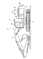
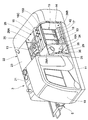
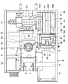
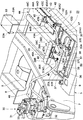
- FIG. 1 is a front view showing a hydraulic excavator according to an embodiment of the present invention. It is a perspective view which shows an upper revolving body in the state which removed the front door and the rear door. It is a top view which shows the state which attached the engine, the turning apparatus, the 1st, 2nd electric equipment etc. on the turning frame. It is a perspective view which shows the state which attached the turning apparatus, the 1st, 2nd electric equipment, and the front partition plate on the turning frame. It is a disassembled perspective view which shows the state which removed the front partition plate in FIG. 4, and removed the cover from the 2nd electric equipment. It is a disassembled perspective view which shows a 1st electric equipment and a floor board.
- FIG. 1 ist electric equipment and a floor board.
- FIG. 4 is a cross-sectional view of the state in which the first electric device is attached to the swivel frame as seen from the direction of arrows VII-VII in FIG. 3.
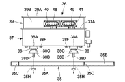
- FIG. 8 is a cross-sectional view of the vibration-proof mount as seen from the direction of arrows VIII-VIII in FIG. 7.
- It is a block diagram which shows the connection relation of the electric motor used for a turning apparatus, and the 1st, 2nd electric equipment.
- It is process drawing of the assembly work which shows the vibration proof mount attachment process which attaches the vibration proof mount to the 1st electric equipment.
- FIGS. 1 to 13 an embodiment of the construction machine according to the present invention will be described in detail with reference to FIGS. 1 to 13 by taking as an example a case where the construction machine is applied to a hydraulic excavator.
- an electric motor used for a turning device will be described as an example of the electric device.
- 1 indicates a hydraulic excavator as a typical example of a construction machine.
- the vehicle body of the hydraulic excavator 1 includes a self-propelled crawler-type lower traveling body 2 and an upper revolving body 3 that is turnably mounted on the lower traveling body 2.
- a working device 4 is provided on the front side of the upper swing body 3 so as to be able to move up and down, and the working device 4 performs excavation work of earth and sand.
- the revolving frame 5 indicates a revolving frame which is a base of the upper revolving structure 3, and the revolving frame 5 forms a strong support structure.
- the revolving frame 5 is formed in a thick flat plate shape and extends in the front and rear directions, and the front and rear surfaces standing on the bottom plate 6 and facing left and right.
- Left vertical plate 7 and right vertical plate 8 extending in the direction, a left extended beam 9 extending leftward from the left vertical plate 7, and a right extended beam extending rightward from the right vertical plate 8.
- a left side frame 11 that is fixed to the front end side of each left extending beam 9 and extends in the front and rear directions
- a right side frame 12 that is fixed to the front end side of each right extending beam 10 and extends in the front and rear directions. It is roughly constituted by.
- a swiveling device 30 described later is provided between the left and right vertical plates 7 and 8 at an intermediate portion in the front and rear direction of the bottom plate 6.
- the working device 4 is attached to the front end sides of the left and right vertical plates 7 and 8, and the counterweight 20 described later is attached to the rear end sides of the left and right vertical plates 7 and 8. Yes.
- a floor plate mounting seat 11A to which a left end side of a floor plate 35 described later is attached is fixed to the inner surface of the left side frame 11 by means such as welding.
- a floor plate mounting bracket 6A to which the right end side of the floor plate 35 is mounted is fixed by means such as welding.
- the position where the floor plate mounting seat 11 ⁇ / b> A and the floor plate mounting bracket 6 ⁇ / b> A are provided is a position 5 ⁇ / b> A of a utility chamber 29 (accommodating space) described later in the revolving frame 5.
- An engine 13 as a prime mover is provided on the rear side of the turning frame 5 and is located on the front side of the counterweight 20.
- the engine 13 is arranged in a horizontally placed state extending in the left and right directions on the vertical plates 7 and 8 of the revolving frame 5.
- a cooling fan 13 ⁇ / b> A is attached to the left end side of the engine 13, and a hydraulic pump 14 is attached to the right end side of the engine 13.
- the hydraulic pump 14 supplies pressure oil for operation to various hydraulic actuators mounted on the hydraulic excavator 1.
- a heat exchanger 15 is mounted on the left side of the engine 13.
- the heat exchanger 15 is formed as one unit including a support frame body 16, a radiator 17 supported by the support frame body 16, an oil cooler 18, and the like, and is detachably attached to the revolving frame 5.
- the support frame 16 of the heat exchanger 15 includes a front partition plate 16A that faces the front partition cover 25 and a utility chamber 29, which will be described later, a rear partition plate 16B that is provided on the front side of the counterweight 20, and these front partitions.
- the plate 16A is composed of a connecting plate 16C that connects the upper end sides of the rear partition plate 16B.
- the support frame 16 supports a radiator 17 that cools engine cooling water, an oil cooler 18 that cools hydraulic oil, and the like.
- the cab 19 is provided on the left side of the front part of the swivel frame 5, and the cab 19 defines a cab.
- a counterweight 20 is provided on the rear end side of the swivel frame 5, and the counterweight 20 balances the weight with the work device 4.
- a hydraulic oil tank 21 is provided on the right side of the front portion of the revolving frame 5, and the hydraulic oil tank 21 stores hydraulic oil supplied to various hydraulic actuators.
- the building cover 22 denotes a building cover provided on the revolving frame 5 that is located on the front side of the counterweight 20.
- the building cover 22 covers the engine 13, the hydraulic pump 14, the heat exchanger 15 and the like mounted on the revolving frame 5.
- the building cover 22 includes a top plate 23, a bonnet 24, a support frame 16 of the heat exchanger 15, a front partition cover 25, which will be described later, a left front door 26, and a left rear door 27.
- the upper side of the building cover 22 is partitioned by an upper surface plate 23 and a bonnet 24.
- the left side of the building cover 22 is partitioned by a left front door 26 and a left rear door 27, and the right side of the building cover 22 is partitioned by a right door (not shown).
- the front side of the building cover 22 is partitioned by the hydraulic oil tank 21 and the front partition cover 25, and the rear side of the building cover 22 is a rear partition plate 16B and a counterweight 20 that constitute the support frame body 16 of the heat exchanger 15. It is partitioned by.
- a front partition cover 25 is provided between the cab 19 and the heat exchanger 15, and the front partition cover 25 constitutes a part of the building cover 22.
- the front partition cover 25 faces the support frame body 16 (front partition plate 16A) of the heat exchanger 15 with an interval in the front and rear directions, and partitions the left front side of the building cover 22.
- the left front door 26 is attached to the front partition cover 25 so as to be openable and closable, and the left front door 26 constitutes a door cover according to the present invention.
- the left front door 26 is rotatably supported by the front partition cover 25 via a hinge member, and rotates in the front and rear directions around the position of the front partition cover 25, thereby opening a utility chamber 29 described later. Open and close.
- a left rear door 27 is provided on the rear side of the left front door 26, and the left rear door 27 pivots on a rear partition plate 16B constituting the support frame 16 of the heat exchanger 15 via a hinge member. Supported as possible.
- the left rear door 27 opens and closes a heat exchanger front chamber 28B, which will be described later, by rotating in the front and rear directions around the position of the rear partition plate 16B.
- the machine room 28 indicates a machine room formed in the building cover 22.
- the machine room 28 is defined by an upper plate 23, a bonnet 24, a left front door 26, a left rear door 27 and a right door (not shown) that constitute the building cover 22, a counterweight 20, and a hydraulic oil tank 21. It is made.
- the machine room 28 includes an engine room 28A and a heat exchanger front room 28B which are adjacent to each other with the heat exchanger 15 interposed therebetween.
- the engine room 28A is a space in which the engine 13, the hydraulic pump 14 and the like are accommodated.
- the engine room 28A includes the top plate 23, the bonnet 24 and the right door (not shown) of the building cover 22, and the heat exchanger 15.
- the support frame 16, the counterweight 20, and the hydraulic oil tank 21 are defined.
- the heat exchanger front chamber 28B is formed on the opposite side of the engine chamber 28A with the heat exchanger 15 in between.
- This heat exchanger front chamber 28 ⁇ / b> B is defined by the top plate 23 and the left rear door 27 constituting the building cover 22, and the heat exchanger 15, and is configured to be opened and closed by the left rear door 27. ing.
- a second electrical device 42 described later is provided in the heat exchanger front chamber 28B.
- the utility chamber 29 indicates a utility room as a storage space formed in the building cover 22 together with the machine room 28.
- the utility chamber 29 is defined by an upper plate 23 and a left front door 26 that constitute the building cover 22, and a front partition plate 16 ⁇ / b> A that constitutes the support frame 16 of the heat exchanger 15.
- an air cleaner 29A for cleaning the intake air sucked into the engine 13 is disposed.
- the lower side of the utility chamber 29 is closed by a floor plate 35 described later, and a first electric device 36 described later is attached on the floor plate 35.
- 30 indicates a turning device mounted on the turning frame 5.
- the swivel device 30 is positioned between the left and right vertical plates 7 and 8 constituting the swivel frame 5 and is erected at the center of the bottom plate 6.
- the turning device 30 turns the upper turning body 3 supported on the lower traveling body 2, and includes a hydraulic motor 31, an electric motor 33 described later, and a speed reducer 32.
- the turning device 30 is a so-called hybrid turning device in which the hydraulic motor 31 and the electric motor 33 cooperate to drive the upper turning body 3 to turn.
- the electric motor 33 denotes an AC type electric motor as an electric device, and the electric motor 33 constitutes a rotation source of the turning device 30 together with the hydraulic motor 31.
- the electric motor 33 is attached to the upper end part of the reduction gear 32 which comprises the turning apparatus 30, as shown in FIG. 4 and FIG.
- the speed reducer 32 is directly attached to the bottom plate 6 of the revolving frame 5 using bolts or the like without using a vibration isolating member or the like.
- a hydraulic motor 31 is attached to the upper end side of the electric motor 33.
- 34 indicates a mounted device assembly disposed in the utility chamber 29, and the mounted device assembly 34 includes a floor plate 35, a first electrical device 36, and a vibration isolation mount 38 which will be described later.
- the mounted device assembly 34 is formed as a single assembly (subassembly) by previously assembling the floor plate 35 and the first electric device 36 via the vibration-proof mount 38.
- the mounted device assembly 34 is attached to the revolving frame 5 at the position of the utility chamber 29 shown in FIG.
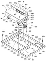
- the floor plate 35 is a floor plate that constitutes a part of the revolving frame 5 and closes the lower side of the utility chamber 29, and the floor plate 35 serves as a base of the mounted device assembly 34. As shown in FIGS. 6 and 7, the floor plate 35 is formed in a rectangular frame shape as a whole, and is detachably attached to the revolving frame 5, and a first electric device 36 to be described later is attached.
- the floor plate 35 includes a flat mounting surface portion 35A to which the first electric device 36 is mounted, an outer frame portion 35B bent upward from the outer peripheral edge of the mounting surface portion 35A, and a plurality of mounting surface portions 35A. It is constituted by a plurality of ribs 35C fixed to the upper surface of the mounting surface portion 35A and the outer frame portion 35B so as to be divided into areas.
- the mounting surface portion 35A is provided with a work hole 35D for attaching / detaching the floor plate 35 to / from the revolving frame 5, a large-diameter hole 35E for attaching / detaching or visually observing a control valve disposed below the floor plate 35, and the like. Yes.
- Bolt insertion holes 35F are respectively provided at the four corners of the mounting surface portion 35A, and bolts 35G as fastening members are inserted into the respective bolt insertion holes 35F. Then, the bolts 35G inserted into the respective bolt insertion holes 35F are screwed to the floor plate mounting seat 11A of the left side frame 11 and the floor plate mounting bracket 6A of the bottom plate 6 shown in FIG. Installed as possible.
- each of the mount mounting holes 35H has a vibration-proof mount 38 to be described later.
- the bolt 38D is inserted.
- a small square-shaped rotation stop hole 35J is provided, and a rotation protrusion 38E of a vibration-proof mount 38 to be described later is engaged with each of the rotation stop holes 35J. It has become.
- two suspension bolt mounting holes 35K are formed at positions where a first electric device 36 described later is sandwiched.
- reference numeral 36 denotes a first electric device disposed in the utility room 29.
- the first electric device 36 is supported on the floor plate 35 in a vibration-proof state via a vibration-proof mount 38 described later, and is connected to the electric motor 33 using a first cable 46 described later.
- the first electric device 36 includes a box 37 described later, and an inverter circuit for converting a drive current supplied to the electric motor 33 from a direct current to an alternating current, in the box 37,
- electrical components (not shown) such as a chopper circuit for boosting and stepping down are accommodated.
- the box body 37 indicates a box that forms the outer shell of the first electric device 36.
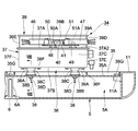
- the box body 37 is a cuboid three-dimensional structure surrounded by an upper surface 37A and a lower surface 37B extending in the horizontal direction, and a front surface 37C, a rear surface 37D, a left side surface 37E, and a right side surface 37F that are substantially perpendicular to the upper surface 37A. It is formed as.
- a cooling water passage (not shown) is provided inside the box body 37, and the heat generated from the electrical components accommodated in the box body 37 is cooled by the cooling water flowing through the cooling water passage. .
- a connector mounting member 39 described later is integrally provided on the upper surface 37A of the box body 37.
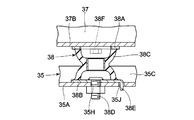
- each of the vibration-proof mounts 38 denotes a plurality of vibration-proof mounts as vibration-proof members, and each of the vibration-proof mounts 38 is provided between a box body 37 and a floor plate 35 constituting the first electric device 36.
- Each anti-vibration mount 38 supports the first electric device 36 in a vibration-proof state with respect to the revolving frame 5, thereby suppressing a large vibration of the upper revolving structure 3 from being transmitted to the first electric device 36. is there.
- the anti-vibration mount 38 has a plate-like device-side attachment portion 38 ⁇ / b> A attached to the lower surface 37 ⁇ / b> B of the box 37 and a disk-like attachment attached to the attachment surface portion 35 ⁇ / b> A of the floor plate 35.
- a bolt 38 ⁇ / b> D inserted through the mount mounting hole 35 ⁇ / b> H of the floor plate 35.
- a rotation projection 38E as a rotation stopping member bent at a right angle from the floor plate side mounting portion 38B along the bolt 38D is provided.
- the locking projection 38E engages with a locking hole 35J provided in the floor plate 35 when the bolt 38D is inserted into the mount mounting hole 35H of the floor plate 35.
- the anti-vibration mount 38 attaches the device-side mounting portion 38A to the lower surface 37B of the box 37 using bolts 38F, and inserts the bolts 38D of the anti-vibration mount 38 into the mounting attachment holes 35H of the floor plate 35 and tightens the nuts.
- the first electrical device 36 is attached to the floor plate 35 via the anti-vibration mounts 38 to form the mounted device assembly 34.
- the rotation stop projection 38E provided on the floor plate side mounting portion 38B of the vibration isolating mount 38 is engaged with the rotation stop hole 35J provided on the floor plate 35.
- the anti-rotation protrusion 38E can prevent the vibration-proof mount 38 from rotating around the bolt 38D due to vibration, thereby improving the assemblability and preventing the vibration-proof mount 38 from loosening.
- the connector mounting member 39 provided in the box body 37 will be described.
- the connector attachment member 39 is provided on the upper surface 37 ⁇ / b> A of the box body 37 is illustrated.
- the present invention is not limited to this, and the connector mounting member 39 may be provided on the outer surface of any one of the front surface 37C, the rear surface 37D, the left side surface 37E, and the right side surface 37F.
- the connector mounting member 39 indicates a connector mounting member projecting on the upper surface 37A of the box 37.
- the connector mounting member 39 is formed as a rectangular parallelepiped three-dimensional structure having an outer shape with a smaller length dimension in the front and rear directions than the box body 37. That is, the connector mounting member 39 has an upper surface 39A that faces the upper surface 37A of the box 37 and extends horizontally, and a front surface 39B, a rear surface 39C, a left side surface 39D, and a right side surface 39E that are substantially perpendicular to the upper surface 39A. It is formed in a rectangular parallelepiped shape surrounded by.
- the connector mounting member 39 has an opening on the lower surface side and communicates with the inside of the box body 37, and a cable is inserted into the box body 37 through the opening.
- the connector mounting member 39 is disposed at a portion of the upper surface 37A of the box body 37 that is shifted to the rear surface 37D side. Therefore, the front surface 39B of the connector mounting member 39 is retracted to the rear side (rear surface 37D side) of the front surface 37C of the box body 37.
- the upper surface 37A of the box body 37 includes an attachment portion 37A1 provided with the connector attachment member 39 and a remaining portion 37A2 positioned in front of the front surface 39B of the connector attachment member 39 excluding the attachment portion 37A1. It has become.
- Reference numerals 40 and 41 denote first and second device-side connectors provided side by side on the front surface 39B of the connector mounting member 39.
- the first and second device-side connectors 40 and 41 are connected to electrical components such as an inverter circuit housed in the box 37.
- a later-described cable-side connector 46A is connected to the first device-side connector 40
- a later-described cable-side connector 47A is connected to the second device-side connector 41.
- the second electric device 42 shows the 2nd electric equipment arrange
- the second electric device 42 is connected to the first electric device 36 using a second cable 47 described later.
- the second electric device 42 includes a box 43 and an electric component (not shown) including a capacitor and a battery such as a battery housed in the box 43.
- the electric storage device in the second electric device 42 stores electric energy for driving the electric motor 33. That is, the electric storage device in the second electric device 42 charges the regenerative energy generated by the electric motor 33 when the electric motor 33 is braked as electric energy and discharges the electric energy toward the electric motor 33.
- the second electric device 42 is configured by connecting a plurality of capacitors.
- the box 43 is formed as a three-dimensional structure composed of a rectangular parallelepiped extending in the front and rear directions surrounded by the upper surface 43A, the lower surface, the front surface 43B, the rear surface, the left side surface 43C, and the right side surface.
- the box body 43 is supported by the revolving frame 5 in a vibration-proof state via a vibration-proof mount (not shown) similarly to the box body 37 described above.
- a cooling water passage (not shown) is provided inside the box body 43, and the heat generated from the electrical components accommodated in the box body 43 is cooled by the cooling water flowing through the cooling water passage. .
- the connector mounting member 44 provided in the box 43 will be described.
- the connector mounting member 44 is provided on the upper surface 43A of the box 43 is illustrated.
- the present invention is not limited to this, and the connector attachment member 44 may be provided on the outer surface of any one of the front surface 43B, the rear surface, the left side surface 43C, and the right side surface of the box body 43.
- the connector mounting member 44 denotes a connector mounting member protruding on the upper surface 43A of the box 43.
- the connector mounting member 44 is surrounded by an upper surface 44A, a front surface 44B, a rear surface 44C, a left side surface 44D, and a right side surface, and is a three-dimensional structure made of a rectangular parallelepiped having an outer shape whose front and rear length dimensions are smaller than those of the box body 43. It is formed as a body.
- the connector mounting member 44 has an opening on the lower surface side and communicates with the inside of the box 43, and a cable is inserted into the box 43 through the opening.
- the connector mounting member 44 is disposed at a portion of the upper surface 43A of the box body 43 that is shifted to the rear surface side. Therefore, the front surface 44B of the connector mounting member 44 is retracted to the rear side of the front surface 43B of the box body 43. Thereby, the upper surface 43A of the box body 43 is formed from the attachment part 43A1 provided with the connector attachment member 44 and the remaining part 43A2 positioned in front of the front surface 44B of the connector attachment member 44 excluding the attachment part 43A1. It has become.
- the 45 indicates a third device-side connector provided on the front surface 44B of the connector mounting member 44.
- the third device-side connector 45 is connected to an electrical component housed in the box 43.
- the third device-side connector 45 is connected to a cable-side connector 47B described later.
- 46 indicates a first cable for electrically connecting the electric motor 33 and the first electric device 36.
- a cable-side connector 46A having a connection terminal (not shown) disposed therein is provided at the end of the first cable 46 on the first electrical device 36 side.
- the cable side connector 46 ⁇ / b> A of the first cable 46 is configured to be connected to the first device side connector 40 attached to the connector attachment member 39 of the first electrical device 36.
- the vicinity of the cable-side connector 46A of the cable-side connector 46A and the first cable 46 is in the upper surface 37A (remaining portion 37A2) of the box 37 that constitutes the first electrical device 36 when viewed from above. Is in the box.
- cable-side connector 47 indicates a second cable for electrically connecting the first electric device 36 and the second electric device 42.
- cable-side connectors 47A and 47B having connection terminals (not shown) disposed therein are provided.
- the cable-side connector 47A on one end side is connected to the second device-side connector 41 attached to the connector attachment member 39 of the first electric device 36.
- the cable-side connector 47B on the other end side is connected to a third device-side connector 45 attached to the connector attachment member 44 of the second electric device 42.
- a portion of the cable-side connector 47A and the second cable 47 in the vicinity of the cable-side connector 47A is accommodated in the upper surface 37A of the box 37 constituting the first electric device 36 when viewed from above. Further, a portion of the cable-side connector 47B and the second cable 47 in the vicinity of the cable-side connector 47B is accommodated in an upper surface 43A (remaining portion 43A2) of the box body 43 constituting the second electric device 42 as viewed from above. .
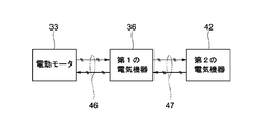
- the electric motor 33 and the first electric device 36 are electrically connected via the first cable 46, and the first electric device 36 and the second electric device 42 are connected. Are electrically connected via a second cable 47.
- the electric energy discharged from the second electric device 42 is supplied to the electric motor 33 as an alternating current through the first electric device 36, and the electric motor 33 is driven to rotate. To do.
- the swing device 30 is braked, the regenerative energy generated by the inertial rotation of the electric motor 33 is stored in the second electric device 42.
- first and second mounting seats denote first and second mounting seats as clamp fixing portions provided on the upper surface 37 ⁇ / b> A of the box 37 of the first electric device 36.
- These mounting seats 48 and 49 are for fixing first and second clamp members 50 and 51 to be described later.
- each mounting seat 48 and 49 is comprised, for example by a hexagon nut, and is being fixed to the remaining part 37A2 among the upper surfaces 37A which comprise the box 37 using means, such as welding. That is, the mounting seats 48 and 49 are provided in the vicinity of the connector mounting member 39 in the box 37 of the first electrical device 36 and in front of the first and second device-side connectors 40 and 41. Yes.
- the first clamp member 50 denotes a first clamp member provided in the box 37 of the first electric device 36, and the first clamp member 50 is attached to the first attachment seat 48.
- the first clamp member 50 clamps the vicinity of the cable side connector 46A of the first cable 46, for example, the cable end portion where the cable side connector 46A is provided.
- the first clamp member 50 is fastened to the first mounting seat 48 provided on the upper surface 37 ⁇ / b> A of the box body 37 using the bolt 50 ⁇ / b> A.
- the cable-side connector 46A is connected to the connector mounting member 39 provided on the box 37 of the first electrical device 36, and the end of the first cable 46 connects the first clamp member 50 to the connector 37. And is fixed to a box 37 of the first electric device 36. Thereby, the vibration transmitted to the end of the first cable 46 can be matched with the vibration transmitted to the cable-side connector 46A. As a result, it is possible to suppress an excessive external force from being transmitted to the connection terminal of the cable side connector 46A.
- Reference numeral 51 denotes a second clamp member provided in the box 37 of the first electric device 36, and the second clamp member 51 is attached to the second attachment seat 49.
- the second clamp member 51 clamps the vicinity of the cable side connector 47A of the second cable 47, specifically, the one end of the cable provided with the cable side connector 47A.
- the second clamp member 51 is fastened to the second mounting seat 49 provided on the upper surface 37 ⁇ / b> A of the box body 37 using the bolt 51 ⁇ / b> A.
- the third clamp member 52 indicates a third clamp member provided in the remaining portion 43A2 of the upper surface 43A of the box 43 of the second electric device 42.
- the third clamp member 52 is provided in the vicinity of the connector mounting member 44 and on the front side of the third device-side connector 45.
- the third clamp member 52 clamps the vicinity of the cable side connector 47B of the second cable 47, specifically, the cable end on the other side where the cable side connector 47B is provided.
- the third clamp member 52 is fastened using a bolt 52A to a third mounting seat (not shown) provided on the upper surface 43A of the box body 43.
- the cable-side connector 47A is connected to the connector mounting member 39 provided on the box 37 of the first electrical device 36, and the one end portion of the second cable 47 is connected to the second clamp 47. It is fixed to the box 37 of the first electric device 36 through the member 51. Thereby, the vibration generated in the second cable 47, the vibration transmitted to a part of the second cable 47, and the vibration transmitted to the cable-side connector 47A can be matched.
- the cable-side connector 47B is connected to a connector mounting member 44 provided on the box 43 of the second electric device 42, and the other end of the second cable 47 is connected to the third clamp member 52. It is being fixed to the box 43 of the 2nd electric equipment 42 via. Thereby, the vibration generated in the second cable 47 and the vibration transmitted to the other end of the second cable 47 can be matched with the vibration transmitted to the cable-side connector 47B.
- the cover 53 indicates a cover attached to the box 43 of the second electric device 42.
- the cover 53 is formed of a plate body bent into an L-shaped cross section, and is fixed to the box body 43 and the connector mounting member 44 constituting the second electric device 42 using a plurality of bolts 53A.
- the cover 53 covers the third device-side connector 45 attached to the connector attachment member 44 and the cable-side connector 47B of the second cable 47 connected to the third device-side connector 45.
- the operator when performing maintenance and inspection work on the heat exchanger 15 in the heat exchanger front chamber 28 ⁇ / b> B, the operator does not prepare the third device side connector 45 or the cable side connector 47 ⁇ / b> B of the second cable 47.
- the cover 53 can be prevented from stepping on.
- each suspension bolt 54 shows two suspension bolts as rope hooks attached to the attachment surface portion 35A of the floor plate 35 (see FIG. 12).
- Each suspension bolt 54 is fixed to two locations sandwiching the first electrical device 36 by being tightened with a nut while being inserted into the suspension bolt mounting hole 35K of the floor plate 35.
- each suspension bolt 54 is provided with a rope 55 for hanging work being hooked.
- the suspension bolts 54 may be provided at three or more locations according to the weight balance of the mounted device assembly 34.
- the hydraulic excavator 1 has the above-described configuration.
- the hydraulic excavator 1 is self-propelled to the work site by the lower traveling body 2, and the upper revolving body 3 is swung by the swiveling device 30 while working. Sediment excavation work is performed using the device 4.
- the swing frame 5 vibrates greatly when the hydraulic excavator 1 is operated. Therefore, the turning device 30 directly attached to the turning frame 5 also vibrates greatly together with the turning frame 5.
- the first electrical device 36 disposed in the utility chamber 29 is supported by a floor plate 35 that closes the lower side of the utility chamber 29 via a vibration isolation mount 38. For this reason, the vibration transmitted to the first electrical device 36 is smaller than the vibration transmitted to the turning device 30.
- the second electric device 42 disposed in the heat exchanger front chamber 28B is also supported by the revolving frame 5 via a vibration-proof mount (not shown). For this reason, the vibration transmitted to the second electrical device 42 is smaller than the vibration transmitted to the turning device 30.
- the vibration transmitted to the turning device 30 and the vibration transmitted to the first electric device 36 and the second electric device 42 are different from each other.
- a connector mounting member 39 protrudes from the upper surface 37A of the box 37 constituting the first electric device 36, and the first device side is provided on the front surface 39A of the connector mounting member 39.
- a connector 40 and a second device side connector 41 are provided.
- a connector mounting member 44 protrudes from the upper surface 43A of the box 43 constituting the second electric device 42, and a third device side connector 45 is provided on the front surface 44A of the connector mounting member 44.
- the cable side connector 46A provided in the 1st cable 46 is connected to the 1st cable 46A.
- the cable end provided with the cable side connector 46 ⁇ / b> A of the first cable 46 is fixed by the first clamp member 50 disposed on the upper surface 37 ⁇ / b> A of the box body 37.
- both the cable end portion of the first cable 46 provided with the cable-side connector 46A and the cable-side connector 46A can be fixed to the box 37 of the first electrical device 36.
- the vibration transmitted to the first cable 46 and the cable-side connector 46A can be matched. Therefore, even when the vibration transmitted to the electric motor 33 and the vibration transmitted to the first electrical device 36 are different, it is possible to suppress an excessive external force from being transmitted to the connection terminal of the cable-side connector 46A.
- the slight sliding that occurs on the contact surface between the connection terminals of the cable side connector 46A and the first equipment side connector 40 is suppressed, and problems such as corrosion (fretting corrosion), poor contact, and burnout occur. Can be prevented. Accordingly, the electric motor 33 and the first electric device 36 can be stably connected using the first cable 46.
- the cable-side connector 47A provided at one end of the second cable 47 is connected to the connector. It connects with the 2nd apparatus side connector 41 provided in the attachment member 39.
- one end of the second cable 47 is fixed by the second clamp member 51 disposed on the upper surface 37 ⁇ / b> A of the box body 37.
- the cable side connector 47 ⁇ / b> B provided at the other end of the second cable 47 is connected to the third device side connector 45 provided at the connector mounting member 44.
- the other end portion of the second cable 47 is fixed by the third clamp member 52 disposed on the upper surface 43 ⁇ / b> A of the box body 43.
- both the cable end portion of the second cable 47 provided with the cable-side connector 47A and the cable-side connector 47A can be fixed to the box 37 of the first electrical device 36.
- the vibration transmitted to the second cable 47 and the cable-side connector 47A can be matched.
- both the cable end of the second cable 47 provided with the cable-side connector 47B and the cable-side connector 47B can be fixed to the box 43 of the second electrical device 42. Accordingly, the vibration transmitted to the second cable 47 and the cable-side connector 47B can be matched.
- the cable-side connectors 47A and 47B provided on the second cable 47 are different. It is possible to suppress an excessive external force from being transmitted to the connection terminal. As a result, the fine sliding that occurs on the contact surfaces of the connection terminals of the cable-side connector 47A and the second device-side connector 41, and the cable-side connector 47B and the third device-side connector 45 is suppressed, and corrosion (fretting corrosion) occurs. ), Contact failure, burnout, and other problems can be prevented. Therefore, the first electric device 36 and the second electric device 42 can be stably connected using the second cable 47.
- the present embodiment it is possible to prevent an excessive external force from being transmitted to the connection terminal of the cable-side connector 46A provided in the first cable 46, so that the cable-side connector 46A and the first device-side connector 40 can be reduced in size.
- the cable side connectors 47A and 47B and the second and third device sides The connectors 41 and 45 can be reduced in size.
- the space occupied by the cable side connectors 46A, 47A, 47B, the first, second, and third device side connectors 40, 41, 45 can be reduced. Accordingly, when arranging the first and second cables 46 and 47 between the electric motor 33 and the first electric device 36 and between the first electric device 36 and the second electric device 42. Workability can be improved.
- the front surface 39B of the connector mounting member 39 provided on the box body 37 of the first electrical device 36 is shifted to the rear surface 37D side from the front surface 37C of the box body 37.
- the cable side connector 46A of the first cable 46 connected to the first device side connector 40 and the cable side connector 47A of the second cable 47 connected to the second device side connector 41 are Of the upper surface 37A of the box 37, the remaining portion 37A2 (front side of the device-side connectors 40 and 41) excluding the attachment portion 37A1 of the connector attachment member 39 can be stored.
- the front surface 44B of the connector mounting member 44 provided on the box body 43 of the second electric device 42 is shifted to the rear side of the front surface 43B of the box body 43.
- the cable-side connector 47B of the second cable 47 connected to the third device-side connector 45 is a remaining portion 43A2 (excluding the attachment portion 43A1 of the connector attachment member 44 in the upper surface 43A of the box 43 ( It can be stored in the front side of the device-side connector 45).
- the connector mounting member 39 of the first electrical device 36 is formed as a rectangular solid structure, and the first and second device-side connectors 40 and 41 are attached to the front surface 39B of the connector mounting member 39. It is installed. For this reason, the cable side connector 46A of the first cable 46 can be connected to the first device side connector 40 from the horizontal direction. Similarly, the cable-side connector 47A of the second cable 47 can be connected to the second device-side connector 41 from the horizontal direction.
- the connector mounting member 44 of the second electrical device 42 is formed as a rectangular solid structure, and the third device-side connector 45 is mounted on the front surface 44B of the connector mounting member 44. For this reason, the cable side connector 47B of the second cable 47 can be connected to the third device side connector 45 from the horizontal direction.
- the third device-side connector 45 and the cable of the second cable 47 connected to the third device-side connector 45 are provided.
- the side connector 47B can be covered with the cover 53.
- a mounting device assembly 34 including a floor plate 35 that closes the lower side of the utility chamber 29, a first electric device 36 that requires anti-vibration measures, and an anti-vibration mount 38 is assembled in advance. ing. Thereby, workability
- FIG. 10 shows the vibration-proof mount mounting process.
- four anti-vibration mounts 38 (only two are shown) are attached to the lower surface 37B of the box 37 constituting the first electric device 36.
- a bolt 38F is inserted into the device-side mounting portion 38A of the vibration-proof mount 38, and the bolt 38F is screwed into the lower surface 37B of the box 37.
- the vibration-proof mount 38 can be attached in a state where the floor plate-side attachment portion 38B protrudes downward.
- FIG. 11 shows a floor board attaching process.
- the bolts 38D of the vibration isolation mounts 38 attached to the box body 37 are inserted into the respective mount attachment holes 35H of the floor plate 35 and tightened with nuts, and are attached to the floor plate side attachment portions 38B of the vibration isolation mounts 38.
- the first electric device 36 can be attached to the attachment surface portion 35 ⁇ / b> A of the floor plate 35 via the four anti-vibration mounts 38 in an anti-vibration state.
- a mounting device assembly 34 including the bottom plate 35, the first electric device 36, and the vibration isolation mount 38 can be formed.
- the rotation projection 38E provided on the floor plate side mounting portion 38B of the anti-vibration mount 38 engages with the rotation hole 35J provided on the floor plate 35.
- a torsional force does not act on the elastic body 38C, and damage to the elastic body 38C can be prevented.
- the vibration isolating mount 38 can be prevented from rotating around the bolt 38D due to vibration, and the vibration isolating mount 38 can be prevented from loosening.
- FIG. 12 shows the assembly lifting process.
- the mounted device assembly 34 is lifted using the rope 55 and the crane 56.
- two suspension bolts 54 are fixed to the upper surface side of the mounting surface portion 35A of the floor board 35 at a position sandwiching the first electric device 36 from the left and right directions.
- the rope 55 for hanging work is hooked on each of these suspension bolts 54, and the rope 55 is lifted by a crane 56, thereby lifting the mounted device assembly 34.
- the mounted equipment assembly 34 that has been lifted is conveyed to a position 5A of the utility chamber 29 in the revolving frame 5, that is, above the position including the floor plate mounting seat 11A of the left side frame 11 and the floor plate mounting bracket 6A of the bottom plate 6.
- FIG. 13 shows an assembly mounting process.
- the floor plate 35 of the mounted device assembly 34 is lifted by the rope 55 and the crane 56.
- the floor plate 35 is placed on the floor plate mounting seat 11 ⁇ / b> A of the left side frame 11 and the floor plate mounting bracket 6 ⁇ / b> A of the bottom plate 6.
- the bolt 35G is inserted into each bolt insertion hole 35F provided in the floor plate 35 and screwed into the floor plate mounting seat 11A of the left side frame 11 and the floor plate mounting bracket 6A of the bottom plate 6.
- the floor board 35 is fixed to the revolving frame 5, and the mounted device assembly 34 can be attached to the revolving frame 5 at the position 5 ⁇ / b> A of the utility chamber 29.
- this assembly attaching step is performed before the upper surface cover that closes the upper surface of the utility chamber 29 is attached, or the upper surface cover is removed in advance before performing this step.
- the first electric device 36 is attached to the floor plate 35 configured to be detachable from the revolving frame 5 via the vibration-proof mount 38.
- the mounted device assembly 34 can be formed by using the floor plate 35 that is originally a constituent member of the revolving frame 5.
- the utility chamber 29 can be quickly and easily installed simply by attaching the floor plate 35 serving as the base of the mounted device assembly 34 to the position 5A of the utility chamber 29 in the revolving frame 5.
- the first electric device 36 can be disposed in a vibration-proof state.
- the mounting device assembly 34 is formed by attaching the first electric device 36 to the floor plate 35 that is originally a constituent member of the revolving frame 5, thereby reducing the mounting device assembly 34 as much as possible. Can do.
- the mounted device assembly 34 is attached to and removed from the revolving frame 5 at the position 5A of the utility chamber 29, a large work space can be secured around the mounted device assembly 34, and the mounted device assembly The workability when attaching and removing the solid body 34 can be improved.
- the components of the mounted device assembly 34 are compared with the case where a stand made of a member separate from the swivel frame 5 is used.
- the score can be reduced. Therefore, the assembly workability of the mounted device assembly 34 can be improved, and the manufacturing cost of the mounted device assembly 34 can be reduced.
- the mounting equipment assembly 34 can be attached to and removed from the revolving frame 5 from above and below with the rope 55 being used to lift the mounting equipment assembly 34, thereby further improving the workability. be able to.
- a locking projection 38E provided on the floor plate side mounting portion 38B is provided. Can be prevented from rotating with respect to the floor plate 35 by engaging the rotation stop hole 35J of the floor plate 35. For this reason, it is possible to prevent the twisting force from acting on the elastic body 38C, and to prevent the elastic body 38C from being damaged. Further, even if the swing frame 5 vibrates when the hydraulic excavator 1 is operated, it is possible to suppress loosening of the attachment portion between the vibration-proof mount 38 and the floor plate 35. Therefore, the first electric device 36 can be supported on the floor plate 35 fixed to the revolving frame 5 in a stable vibration-proof state for a long period of time.
- the case where the cable body connector 47B of the second cable 47, the third device side connector 45, and the cover 53 that covers the box body 43 constituting the second electric device 42 are provided. Illustrated.
- the present invention is not limited to this, and may be configured as a first modification shown in FIG. 14, for example. That is, a cover 61 is provided on the box body 37 constituting the first electrical device 36, and the cover 61 allows the cable-side connector 46 A of the first cable 46, the cable-side connector 47 A of the second cable 47, It is good also as a structure which covers the 2nd apparatus side connectors 40 and 41.
- FIG. 14 a cover 61 is provided on the box body 37 constituting the first electrical device 36, and the cover 61 allows the cable-side connector 46 A of the first cable 46, the cable-side connector 47 A of the second cable 47, It is good also as a structure which covers the 2nd apparatus side connectors 40 and 41.
- bolt holes female screw holes
- 62 and 63 are formed as clamp fixing portions as in the second modification shown in FIG. It is good also as a structure which fixes a clamp member using the volt
- the electric motor 33 used in the hybrid turning device 30 is described as an example of the electric device mounted on the vehicle body.
- the present invention is not limited to this, and may be applied to, for example, an electric hydraulic pump used as a prime mover.
- the present invention can also be applied to a hybrid prime mover that drives a hydraulic pump by combining an engine 13 and an electric motor for a hydraulic pump.
Abstract
Description
2 下部走行体(車体)
3 上部旋回体(車体)
5 旋回フレーム
5A ユーティリティ室(収容空間)の位置
13 エンジン(原動機)
19 キャブ
22 建屋カバー
26 左前側ドア(ドアカバー)
28 機械室
29 ユーティリティ室(収容空間)
33 電動モータ(電動装置)
34 搭載機器組立体
35 床板
35G ボルト(締結部材)
36 第1の電気機器
37,43 箱体
37A,39A,43A,44A 上面
37B 下面
37C,39B,43B,44B 前面
37D,39C,44C 後面
37E,39D,43C,44D 左側面
37F,39E 右側面
37A1,43A1 取付部位
37A2,43A2 残余の部位
38 防振マウント(防振部材)
38A 機器側取付部
38B 床板側取付部
38C 弾性体
38D ボルト
38E 廻止め突起(廻止め部材)
39,44 コネクタ取付部材
40 第1の機器側コネクタ
41 第2の機器側コネクタ
42 第2の電気機器
45 第3の機器側コネクタ
46 第1のケーブル
46A,47A,47B ケーブル側コネクタ
47 第2のケーブル
48 第1の取付座(クランプ固定部)
49 第2の取付座(クランプ固定部)
50 第1のクランプ部材
51 第2のクランプ部材
52 第3のクランプ部材
53,61 カバー
54 吊りボルト(ロープ掛止め具)
55 ロープ
62,63 ボルト孔(クランプ固定部) 1 Excavator (construction machine)
2 Lower traveling body (car body)
3 Upper swing body (car body)
5 Rotating
19
28
33 Electric motor (electric device)
34
36 1st
38A Equipment
39, 44
49 Second mounting seat (clamp fixing part)
50
55
Claims (11)
- 自走可能な車体(3)と、該車体(3)に搭載された電動装置(33)と、箱体(37,43)内に該電動装置(33)と接続される電気部品を収容し防振部材(38)を用いて前記車体(3)に支持された電気機器(36,42)と、前記電動装置(33)と前記電気機器(36,42)との間を接続するケーブル(46,47)とを備えてなる建設機械において、
前記電気機器(36,42)の箱体(37,43)には、その外面側に位置して当該箱体(37,43)よりも小さな外形形状をもって突出するコネクタ取付部材(39,44)を設け、
前記コネクタ取付部材(39,44)には、前記ケーブル(46,47)の電気機器(36,42)側の端部に設けられたケーブル側コネクタ(46A,47A,47B)が接続される機器側コネクタ(40,41,45)を設け、
前記電気機器(36,42)の箱体(37,43)外面には、前記コネクタ取付部材(39,44)の近傍に位置して前記ケーブル(46,47)の電気機器(36,42)側の端部を固定するクランプ部材(50,51,52)を設ける構成としたことを特徴とする建設機械。 A self-propelled vehicle body (3), an electric device (33) mounted on the vehicle body (3), and electrical parts connected to the electric device (33) are accommodated in a box (37, 43). An electric device (36, 42) supported by the vehicle body (3) using a vibration isolating member (38), and a cable (between the electric device (33) and the electric device (36, 42)) 46, 47),
In the box (37, 43) of the electric device (36, 42), a connector mounting member (39, 44) is located on the outer surface side and protrudes with a smaller outer shape than the box (37, 43). Provided,
Equipment to which the cable side connectors (46A, 47A, 47B) provided at the ends of the cables (46, 47) on the electrical equipment (36, 42) side are connected to the connector mounting members (39, 44). Side connectors (40, 41, 45)
On the outer surface of the box (37, 43) of the electric device (36, 42), the electric device (36, 42) of the cable (46, 47) is located in the vicinity of the connector mounting member (39, 44). A construction machine having a configuration in which a clamp member (50, 51, 52) for fixing a side end portion is provided. - 前記電気機器(36,42)の箱体(37,43)は上面(37A,43A)、下面(37B)および側面(37C,37D,37E,37F,43B,43C)によって囲まれた立体構造体とし、
前記電気機器(36,42)の箱体(37,43)は、その下面(37B)を下にして前記車体(3)上に設けられ、
前記コネクタ取付部材(39,44)は、前記箱体(37,43)の下面(37B)を除くいずれかの外面(37A,43A)に取付け、
前記ケーブル(46,47)の前記ケーブル側コネクタ(46A,47A,47B)は、前記コネクタ取付部材(39,44)が設けられた前記いずれかの外面(37A,43A)のうち、前記コネクタ取付部材(39,44)が取付けられた部位(37A1,43A1)を除いた残余の部位(37A2,43A2)に配置する構成とし、
前記クランプ部材(50,51,52)は、前記コネクタ取付部材(39,44)が設けられた前記いずれかの外面(37A,43A)のうち、前記残余の部位(37A2,43A2)に取付ける構成としてなる請求項1に記載の建設機械。 The box (37, 43) of the electric device (36, 42) is a three-dimensional structure surrounded by an upper surface (37A, 43A), a lower surface (37B) and side surfaces (37C, 37D, 37E, 37F, 43B, 43C). age,
The box (37, 43) of the electric device (36, 42) is provided on the vehicle body (3) with its lower surface (37B) down,
The connector attachment member (39, 44) is attached to any outer surface (37A, 43A) excluding the lower surface (37B) of the box (37, 43),
The cable side connector (46A, 47A, 47B) of the cable (46, 47) is the connector mounting of the outer surface (37A, 43A) provided with the connector mounting member (39, 44). It is set as the structure arrange | positioned in the remaining site | parts (37A2, 43A2) except the site | part (37A1, 43A1) to which the member (39, 44) was attached,
The clamp member (50, 51, 52) is attached to the remaining portion (37A2, 43A2) of any one of the outer surfaces (37A, 43A) provided with the connector attachment member (39, 44). The construction machine according to claim 1. - 前記電気機器(36,42)の箱体(37,43)は上面(37A,43A)、下面(37B)、前面(37C,43B)、後面(37D)、左側面(37E,43C)および右側面(37F)によって囲まれた立体構造体とし、
前記コネクタ取付部材(39,44)は上面(39A,44A)、前面(39B,44B)、後面(39C,44C)、左側面(39D,44D)および右側面(39E)によって囲まれた立体構造体とし、
前記電気機器(36,42)の箱体(37,43)は、下面(37B)を下にして前記車体(3)上に設けられ、
前記コネクタ取付部材(39,44)は、前記箱体(37,43)の下面(37B)を除くいずれかの外面(37A,43A)に設けられ、
前記コネクタ取付部材(39,44)の各面のうち前記箱体(37,43)に対して前記コネクタ取付部材(39,44)が設けられた前記いずれかの外面(37A,43A)と直交する面(39B,44B)には前記機器側コネクタ(40,41,45)を設け、
前記コネクタ取付部材(39,44)に対して前記機器側コネクタ(40,41,45)が設けられた面(39B,44B)の前側にスペースが形成されるように、前記コネクタ取付部材(39,44)は、前記箱体(37,43)の後面(37D)側に片寄せて配置し、
前記ケーブル(46,47)の前記ケーブル側コネクタ(46A,47A,47B)は、前記コネクタ取付部材(39,44)に対して前記機器側コネクタ(40,41,45)が設けられた面(39B,44B)の前方側に位置して前記箱体(37,43)の前記いずれかの外面(37A,43A)に配置する構成とし、
前記クランプ部材(50,51,52)は、前記コネクタ取付部材(39,44)に対して前記機器側コネクタ(40,41,45)が設けられた面(39B,44B)の前方側に位置して前記箱体(37,43)の前記いずれかの外面(37A,43A)に配置する構成としてなる請求項1に記載の建設機械。 The box (37, 43) of the electric device (36, 42) has an upper surface (37A, 43A), a lower surface (37B), a front surface (37C, 43B), a rear surface (37D), a left side surface (37E, 43C) and a right side. A three-dimensional structure surrounded by a surface (37F),
The connector mounting member (39, 44) is a three-dimensional structure surrounded by an upper surface (39A, 44A), a front surface (39B, 44B), a rear surface (39C, 44C), a left side surface (39D, 44D), and a right side surface (39E). Body and
Boxes (37, 43) of the electrical devices (36, 42) are provided on the vehicle body (3) with the lower surface (37B) down,
The connector mounting member (39, 44) is provided on any outer surface (37A, 43A) excluding the lower surface (37B) of the box (37, 43),
Of each surface of the connector mounting member (39, 44), the box (37, 43) is orthogonal to any one of the outer surfaces (37A, 43A) provided with the connector mounting member (39, 44). The device side connectors (40, 41, 45) are provided on the surfaces (39B, 44B),
The connector mounting member (39) is formed such that a space is formed in front of the surface (39B, 44B) on which the device side connector (40, 41, 45) is provided with respect to the connector mounting member (39, 44). , 44) are arranged side by side on the rear surface (37D) side of the box (37, 43),
The cable side connectors (46A, 47A, 47B) of the cables (46, 47) are surfaces (40, 41, 45) provided with the device side connectors (40, 41, 45) with respect to the connector mounting members (39, 44). 39B, 44B) is located on the front side of the box (37, 43) and arranged on any one of the outer surfaces (37A, 43A),
The clamp member (50, 51, 52) is positioned on the front side of the surface (39B, 44B) on which the device side connector (40, 41, 45) is provided with respect to the connector mounting member (39, 44). The construction machine according to claim 1, wherein the construction machine is arranged on any one of the outer surfaces (37A, 43A) of the box (37, 43). - 前記箱体(37,43)のうち前記コネクタ取付部材(39,44)が設けられる前記いずれかの外面(37A,43A)にはクランプ固定部(48,49,62,63)を設け、前記クランプ部材(50,51,52)は前記クランプ固定部(48,49,62,63)に取付ける構成としてなる請求項2に記載の建設機械。 A clamp fixing portion (48, 49, 62, 63) is provided on any one of the outer surfaces (37A, 43A) on which the connector mounting member (39, 44) is provided in the box (37, 43), The construction machine according to claim 2, wherein the clamp member (50, 51, 52) is configured to be attached to the clamp fixing portion (48, 49, 62, 63).
- 前記箱体(37,43)には、前記コネクタ取付部材(39,44)に設けられた前記機器側コネクタ(40,41,45)および当該機器側コネクタ(40,41,45)に接続された前記ケーブル側コネクタ(46A,47A,47B)を覆うカバー(53,61)を設ける構成としてなる請求項1に記載の建設機械。 The box (37, 43) is connected to the device side connector (40, 41, 45) and the device side connector (40, 41, 45) provided on the connector mounting member (39, 44). The construction machine according to claim 1, wherein a cover (53, 61) is provided to cover the cable side connector (46A, 47A, 47B).
- 前記電気機器(36,42)は、前記電動装置(33)と第1のケーブル(46)を用いて接続された第1の電気機器(36)と、前記第1の電気機器(36)と第2のケーブル(47)を用いて接続された第2の電気機器(42)とにより構成し、
前記第1の電気機器(36)の箱体(37)にはインバータ回路を収容し、前記第2の電気機器(42)の箱体(43)には電気エネルギを蓄える蓄電器を収容する構成としてなる請求項1に記載の建設機械。 The electric devices (36, 42) include a first electric device (36) connected to the electric device (33) using a first cable (46), and the first electric device (36). A second electrical device (42) connected using a second cable (47),
The box (37) of the first electric device (36) accommodates an inverter circuit, and the box (43) of the second electric device (42) accommodates a capacitor for storing electric energy. The construction machine according to claim 1. - 前記車体(3)は、支持構造体を構成するフレーム(5)と、該フレーム(5)の前部側に設けられ運転室を画成するキャブ(19)と、前記フレーム(5)の後部側に設けられ前記車体(3)の駆動に必要な原動機(13)を収容すると共に建屋カバー(22)によって覆われた機械室(28)と、前記機械室(28)とともに建屋カバー(22)内に設けられると共に床板(35)によって閉塞され、機器または備品が収容可能な収容空間(29)とを備え、
前記収容空間(29)の前記床板(35)は前記フレーム(5)に対して着脱可能な構成とし、
前記床板(35)と前記電気機器(36)とを前記防振部材(38)を介して予め組立てることにより単一の搭載機器組立体(34)を形成し、
前記搭載機器組立体(34)を形成する前記床板(35)を前記収容空間(29)の位置(5A)で前記フレーム(5)に取付ける構成としてなる請求項1に記載の建設機械。 The vehicle body (3) includes a frame (5) constituting a support structure, a cab (19) provided on the front side of the frame (5) and defining a cab, and a rear portion of the frame (5). A machine room (28) that is provided on the side and houses a prime mover (13) necessary for driving the vehicle body (3) and is covered with a building cover (22), and a building cover (22) together with the machine room (28) A storage space (29) provided inside and closed by a floor plate (35) and capable of storing equipment or fixtures;
The floor plate (35) of the housing space (29) is configured to be detachable from the frame (5),
A single mounting device assembly (34) is formed by pre-assembling the floor plate (35) and the electric device (36) via the vibration isolation member (38),
The construction machine according to claim 1, wherein the floor board (35) forming the mounted equipment assembly (34) is attached to the frame (5) at a position (5A) of the accommodation space (29). - 前記収容空間(29)は、前記キャブ(19)の後部に設けられ側部が開閉可能なドアカバー(26)によって覆われると共に前記床板(35)によって閉塞されたユーティリティ室(29)である請求項7に記載の建設機械。 The accommodation space (29) is a utility chamber (29) provided at a rear portion of the cab (19) and covered with a door cover (26) whose side portions can be opened and closed and closed by the floor plate (35). Item 8. The construction machine according to Item 7.
- 前記防振部材(38)は、前記電気機器(36)に取付けられる機器側取付部(38A)と、前記床板(35)に取付けられる床板側取付部(38B)と、前記機器側取付部(38A)と床板側取付部(38B)との間に設けられた弾性体(38C)と、前記床板側取付部(38B)に設けられ前記床板(35)に挿通されるボルト(38D)とにより構成し、
前記防振部材(38)の機器側取付部(38A)を前記電気機器(36)の下面(37B)に取付けると共に、前記防振部材(38)のボルト(38D)を前記床板(35)に締結することにより前記搭載機器組立体(34)を形成し、
前記搭載機器組立体(34)の床板(35)は、前記フレーム(5)上に載置した状態で締結部材(35G)を用いて当該フレーム(5)に取付ける構成としてなる請求項7に記載の建設機械。 The vibration isolation member (38) includes a device side mounting portion (38A) attached to the electric device (36), a floor plate side mounting portion (38B) attached to the floor plate (35), and the device side mounting portion ( 38A) and a floor plate side mounting portion (38B), and an elastic body (38C) provided by the floor plate side mounting portion (38B) and a bolt (38D) inserted through the floor plate (35). Configure
The device side mounting portion (38A) of the vibration isolation member (38) is attached to the lower surface (37B) of the electric device (36), and the bolt (38D) of the vibration isolation member (38) is attached to the floor plate (35). Forming the on-board equipment assembly (34) by fastening;
The floor board (35) of the said mounting apparatus assembly (34) becomes a structure attached to the said frame (5) using a fastening member (35G) in the state mounted in the said frame (5). Construction machinery. - 前記防振部材(38)の前記床板側取付部(38B)には、前記床板(35)に係合することにより前記床板(35)に対して前記防振部材(38)が回転するのを抑える廻止め部材(38E)を設ける構成としてなる請求項9に記載の建設機械。 By engaging the floor plate (35), the vibration isolation member (38) rotates relative to the floor plate (35) in the floor plate side attachment portion (38B) of the vibration isolation member (38). The construction machine according to claim 9, wherein the construction machine is provided with a rotation-preventing member (38E) to be suppressed.
- 前記搭載機器組立体(34)の床板(35)には、当該搭載機器組立体(34)を吊上げるためのロープ(55)を掛止めするロープ掛止め具(54)を取付ける構成としてなる請求項7に記載の建設機械。 The floor plate (35) of the mounting device assembly (34) is configured to be attached with a rope stopper (54) for hooking a rope (55) for lifting the mounting device assembly (34). Item 8. The construction machine according to Item 7.
Priority Applications (4)
| Application Number | Priority Date | Filing Date | Title |
|---|---|---|---|
| US14/110,255 US9605408B2 (en) | 2011-05-16 | 2012-05-14 | Construction machine |
| KR1020137027031A KR101925163B1 (en) | 2011-05-16 | 2012-05-14 | Construction machine |
| EP12785497.4A EP2711468B1 (en) | 2011-05-16 | 2012-05-14 | Construction machine |
| CN201280024104.5A CN103534418B (en) | 2011-05-16 | 2012-05-14 | Engineering machinery |
Applications Claiming Priority (4)
| Application Number | Priority Date | Filing Date | Title |
|---|---|---|---|
| JP2011109423A JP5325261B2 (en) | 2011-05-16 | 2011-05-16 | Construction machinery |
| JP2011-109425 | 2011-05-16 | ||
| JP2011109425A JP5562901B2 (en) | 2011-05-16 | 2011-05-16 | Construction machinery |
| JP2011-109423 | 2011-05-16 |
Publications (1)
| Publication Number | Publication Date |
|---|---|
| WO2012157606A1 true WO2012157606A1 (en) | 2012-11-22 |
Family
ID=47176923
Family Applications (1)
| Application Number | Title | Priority Date | Filing Date |
|---|---|---|---|
| PCT/JP2012/062295 WO2012157606A1 (en) | 2011-05-16 | 2012-05-14 | Construction machine |
Country Status (5)
| Country | Link |
|---|---|
| US (1) | US9605408B2 (en) |
| EP (1) | EP2711468B1 (en) |
| KR (1) | KR101925163B1 (en) |
| CN (1) | CN103534418B (en) |
| WO (1) | WO2012157606A1 (en) |
Cited By (1)
| Publication number | Priority date | Publication date | Assignee | Title |
|---|---|---|---|---|
| JP2016020601A (en) * | 2014-07-15 | 2016-02-04 | コベルコ建機株式会社 | Hybrid construction machine |
Families Citing this family (14)
| Publication number | Priority date | Publication date | Assignee | Title |
|---|---|---|---|---|
| EP2857599A1 (en) * | 2012-06-04 | 2015-04-08 | Hitachi Construction Machinery Co., Ltd. | Construction machine |
| CA2888604A1 (en) * | 2012-10-29 | 2014-05-08 | Volvo Construction Equipment Ab | Electro hydraulic actuator mounting structure for hybrid type construction machine |
| JP5803985B2 (en) * | 2013-06-14 | 2015-11-04 | コベルコ建機株式会社 | Construction machine routing structure |
| JP6260284B2 (en) * | 2014-01-09 | 2018-01-17 | コベルコ建機株式会社 | Construction machinery side frame |
| JP6303678B2 (en) * | 2014-03-20 | 2018-04-04 | コベルコ建機株式会社 | Upper swing body |
| JP6469381B2 (en) * | 2014-07-28 | 2019-02-13 | 日立建機株式会社 | Hybrid work machine |
| JP6356002B2 (en) * | 2014-07-28 | 2018-07-11 | 日立建機株式会社 | Hybrid work machine |
| KR102301402B1 (en) | 2015-02-03 | 2021-09-13 | 두산인프라코어 주식회사 | Protection device for swing motor of excavator |
| JP6183402B2 (en) * | 2015-04-16 | 2017-08-23 | コベルコ建機株式会社 | Upper swing body of construction machinery |
| JP6522534B2 (en) * | 2016-02-29 | 2019-05-29 | ヤンマー株式会社 | Construction machinery |
| CN109937279B (en) * | 2017-09-29 | 2021-08-03 | 株式会社日立建机Tierra | Construction machine |
| CN109755821B (en) * | 2017-11-01 | 2020-09-15 | 株洲中车时代电气股份有限公司 | Connector anti-vibration fixing device |
| DE102018115036A1 (en) * | 2018-06-22 | 2019-12-24 | Weidemann GmbH | Work vehicle with electrical energy storage |
| US11651910B2 (en) | 2020-12-10 | 2023-05-16 | Teradyne, Inc. | Inductance control system |
Citations (4)
| Publication number | Priority date | Publication date | Assignee | Title |
|---|---|---|---|---|
| JPH03145079A (en) | 1989-10-27 | 1991-06-20 | Dai Ichi Denshi Kogyo Kk | Connector for thin coaxial cable |
| JPH0757709A (en) * | 1993-04-01 | 1995-03-03 | Gnb Ind Battery Co | Storage battery tray assembly for sealed type lead - acid storage battery and electric drive type vehicle |
| JP2008044408A (en) * | 2006-08-10 | 2008-02-28 | Hitachi Constr Mach Co Ltd | Battery holding structure of battery-driven construction machine |
| JP2010270555A (en) | 2009-05-25 | 2010-12-02 | Kobelco Contstruction Machinery Ltd | Frame for working machine |
Family Cites Families (6)
| Publication number | Priority date | Publication date | Assignee | Title |
|---|---|---|---|---|
| JPH07302646A (en) * | 1994-05-06 | 1995-11-14 | Hosiden Corp | Connector for interface |
| JP2002172979A (en) | 2000-12-08 | 2002-06-18 | Komatsu Ltd | Console box mounting structure of vehicle |
| JP3997208B2 (en) | 2004-02-17 | 2007-10-24 | トヨタ自動車株式会社 | Connector fixing structure |
| JP4842635B2 (en) * | 2005-12-26 | 2011-12-21 | 日立建機株式会社 | Construction machinery |
| JP5425508B2 (en) * | 2009-03-30 | 2014-02-26 | 矢崎総業株式会社 | Motor cable device and cable body manufacturing method of motor cable device |
| CN201549861U (en) * | 2009-10-29 | 2010-08-11 | 重庆长安汽车股份有限公司 | High-voltage shielded cable connector used for hybrid electric vehicle |
-
2012
- 2012-05-14 EP EP12785497.4A patent/EP2711468B1/en active Active
- 2012-05-14 CN CN201280024104.5A patent/CN103534418B/en active Active
- 2012-05-14 KR KR1020137027031A patent/KR101925163B1/en active IP Right Grant
- 2012-05-14 WO PCT/JP2012/062295 patent/WO2012157606A1/en active Application Filing
- 2012-05-14 US US14/110,255 patent/US9605408B2/en active Active
Patent Citations (4)
| Publication number | Priority date | Publication date | Assignee | Title |
|---|---|---|---|---|
| JPH03145079A (en) | 1989-10-27 | 1991-06-20 | Dai Ichi Denshi Kogyo Kk | Connector for thin coaxial cable |
| JPH0757709A (en) * | 1993-04-01 | 1995-03-03 | Gnb Ind Battery Co | Storage battery tray assembly for sealed type lead - acid storage battery and electric drive type vehicle |
| JP2008044408A (en) * | 2006-08-10 | 2008-02-28 | Hitachi Constr Mach Co Ltd | Battery holding structure of battery-driven construction machine |
| JP2010270555A (en) | 2009-05-25 | 2010-12-02 | Kobelco Contstruction Machinery Ltd | Frame for working machine |
Non-Patent Citations (1)
| Title |
|---|
| See also references of EP2711468A4 * |
Cited By (1)
| Publication number | Priority date | Publication date | Assignee | Title |
|---|---|---|---|---|
| JP2016020601A (en) * | 2014-07-15 | 2016-02-04 | コベルコ建機株式会社 | Hybrid construction machine |
Also Published As
| Publication number | Publication date |
|---|---|
| US9605408B2 (en) | 2017-03-28 |
| KR101925163B1 (en) | 2018-12-04 |
| EP2711468B1 (en) | 2017-03-08 |
| EP2711468A1 (en) | 2014-03-26 |
| CN103534418A (en) | 2014-01-22 |
| KR20140030150A (en) | 2014-03-11 |
| CN103534418B (en) | 2016-06-08 |
| US20140021781A1 (en) | 2014-01-23 |
| EP2711468A4 (en) | 2014-12-31 |
Similar Documents
| Publication | Publication Date | Title |
|---|---|---|
| WO2012157606A1 (en) | Construction machine | |
| KR101464555B1 (en) | Generator motor and work machine | |
| KR101464557B1 (en) | Generator motor and work machine | |
| US9790662B2 (en) | Hybrid-type working machine | |
| JP5416158B2 (en) | Generator motor and work machine | |
| JP5562901B2 (en) | Construction machinery | |
| JP5325261B2 (en) | Construction machinery | |
| JP5548576B2 (en) | Battery pack | |
| US20160164055A1 (en) | Structure for mounting battery on vehicle | |
| JP2024009110A (en) | Construction machine | |
| JP5957475B2 (en) | Hybrid construction machine | |
| JP7008605B2 (en) | Construction machinery | |
| JP5951794B2 (en) | Construction machinery | |
| JP5386378B2 (en) | Engine room for construction machinery | |
| JP6707387B2 (en) | Hybrid work machine | |
| WO2023190179A1 (en) | Swiveling work machine | |
| WO2023145246A1 (en) | Battery device and work machine | |
| WO2021020168A1 (en) | Driving device and mount for construction machine | |
| CN106065641B (en) | Upper slewing body of construction machine | |
| JP6385069B2 (en) | Excavator | |
| JP2014020111A (en) | Control box for construction machine |
Legal Events
| Date | Code | Title | Description |
|---|---|---|---|
| 121 | Ep: the epo has been informed by wipo that ep was designated in this application |
Ref document number: 12785497 Country of ref document: EP Kind code of ref document: A1 |
|
| WWE | Wipo information: entry into national phase |
Ref document number: 14110255 Country of ref document: US |
|
| ENP | Entry into the national phase |
Ref document number: 20137027031 Country of ref document: KR Kind code of ref document: A |
|
| REEP | Request for entry into the european phase |
Ref document number: 2012785497 Country of ref document: EP |
|
| WWE | Wipo information: entry into national phase |
Ref document number: 2012785497 Country of ref document: EP |
|
| NENP | Non-entry into the national phase |
Ref country code: DE |