WO2012157459A1 - 立体視用画像生成システム - Google Patents
立体視用画像生成システム Download PDFInfo
- Publication number
- WO2012157459A1 WO2012157459A1 PCT/JP2012/061670 JP2012061670W WO2012157459A1 WO 2012157459 A1 WO2012157459 A1 WO 2012157459A1 JP 2012061670 W JP2012061670 W JP 2012061670W WO 2012157459 A1 WO2012157459 A1 WO 2012157459A1
- Authority
- WO
- WIPO (PCT)
- Prior art keywords
- image
- stereoscopic image
- stereoscopic
- camera
- generation system
- Prior art date
- Legal status (The legal status is an assumption and is not a legal conclusion. Google has not performed a legal analysis and makes no representation as to the accuracy of the status listed.)
- Ceased
Links
Images





Classifications
-
- G—PHYSICS
- G06—COMPUTING OR CALCULATING; COUNTING
- G06T—IMAGE DATA PROCESSING OR GENERATION, IN GENERAL
- G06T5/00—Image enhancement or restoration
- G06T5/70—Denoising; Smoothing
-
- G—PHYSICS
- G06—COMPUTING OR CALCULATING; COUNTING
- G06T—IMAGE DATA PROCESSING OR GENERATION, IN GENERAL
- G06T7/00—Image analysis
- G06T7/10—Segmentation; Edge detection
- G06T7/13—Edge detection
-
- H—ELECTRICITY
- H04—ELECTRIC COMMUNICATION TECHNIQUE
- H04N—PICTORIAL COMMUNICATION, e.g. TELEVISION
- H04N13/00—Stereoscopic video systems; Multi-view video systems; Details thereof
- H04N13/20—Image signal generators
- H04N13/204—Image signal generators using stereoscopic image cameras
- H04N13/207—Image signal generators using stereoscopic image cameras using a single two-dimensional [2D] image sensor
- H04N13/232—Image signal generators using stereoscopic image cameras using a single two-dimensional [2D] image sensor using fly-eye lenses, e.g. arrangements of circular lenses
-
- G—PHYSICS
- G06—COMPUTING OR CALCULATING; COUNTING
- G06T—IMAGE DATA PROCESSING OR GENERATION, IN GENERAL
- G06T2207/00—Indexing scheme for image analysis or image enhancement
- G06T2207/10—Image acquisition modality
- G06T2207/10004—Still image; Photographic image
- G06T2207/10012—Stereo images
Definitions
- the present invention relates to a stereoscopic image generation system.
- a stereoscopic display device that displays a stereoscopic image to an observer has been conventionally known (for example, see JP-A-6-3122).
- the stereoscopic display device includes a spectacle type using special spectacles such as liquid crystal shutter spectacles and a naked eye type not using special spectacles. Regardless of which type of stereoscopic display device is used, different stereoscopic images are displayed on the left and right eyes of the observer so that the observer can see the stereoscopic image.
- An object of the present invention is to provide a stereoscopic image generation system capable of easily obtaining a stereoscopic image.
- a stereoscopic image generation system includes a camera including a fisheye lens, and a processing device that generates a stereoscopic image by processing an image captured by the camera.
- a detection unit that performs edge detection, and identifies a subject included in the image based on a result of edge detection, determines a jumping amount of the identified subject, and processes the image according to the determined popping amount
- a generating unit that generates the stereoscopic image.
- a stereoscopic image can be easily obtained.
- FIG. 1 is a block diagram showing a stereoscopic image generation system as a first embodiment of the present invention.
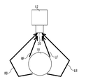
- FIG. 2 is a conceptual diagram showing that the camera also captures reflected light from behind the subject.
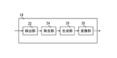
- FIG. 3 is a functional block diagram of the processing apparatus shown in FIG.
- FIG. 4 is a figure used to explain the process executed by the generation unit.
- FIG. 5 is a figure used for explaining the processing executed by the generation unit.
- FIG. 6 is a functional block diagram of a processing apparatus included in the stereoscopic image generation system as the application example 1 of the first embodiment.
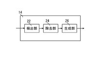
- FIG. 7 is a functional block diagram of a processing apparatus included in the stereoscopic image generation system as the application example 2 of the first embodiment.
- FIG. 8 is a block diagram showing a stereoscopic image generation system as a second embodiment of the present invention.
- FIG. 9 is a functional block diagram of the processing apparatus shown in FIG.
- a stereoscopic image generation system includes a camera including a fisheye lens and a processing device that generates a stereoscopic image by processing an image captured by the camera.
- a detection unit that detects an edge of the image, and identifies a subject included in the image based on a result of edge detection, determines a pop-out amount of the specified subject, and determines the image according to the determined pop-out amount
- a generation unit that generates the stereoscopic image (first configuration).
- the camera includes a fisheye lens. Therefore, the image captured by the camera also captures reflected light from behind the subject. As a result, information necessary for determining the pop-out amount of the subject is included in the image captured by the camera. As a result, it is easy to set the pop-out amount of the subject even when shooting with one camera. Accordingly, a stereoscopic image can be easily obtained.
- the second configuration is a configuration in which, in the first configuration, the processing device further includes a removal unit that removes noise from the stereoscopic image. In such a configuration, the image quality of the stereoscopic image is improved.
- the third configuration is a configuration including a display device that displays the stereoscopic image in the first or second configuration. In such a configuration, an image taken by the camera can be displayed immediately.
- the fourth configuration is a configuration in which, in the third configuration, the processing device further includes a conversion unit that converts data of the stereoscopic image in accordance with the display device. In such a configuration, a stereoscopic image corresponding to the display device can be displayed.
- the fifth configuration is a configuration in which, in any one of the first to fourth configurations, the fisheye lens is a diagonal fisheye lens. In such a configuration, compared to the case where the fisheye lens is a circumferential fisheye lens, the burden on processing an image is reduced.
- the sixth configuration is a configuration in which in any one of the first to fifth configurations, the processing device further includes a storage unit that stores the stereoscopic image.
- FIG. 1 shows a stereoscopic image generation system 10 as a first embodiment of the present invention.
- Applications of the stereoscopic image generation system 10 include, for example, a television receiver and a game machine.
- the stereoscopic image generation system 10 includes a camera 12, a processing device 14, and a display device 16.
- the processing device 14 processes the image captured by the camera 12 to obtain a stereoscopic image.
- the stereoscopic image is displayed on the display device 16 so that the observer can see the stereoscopic image.
- the camera 12 photographs the subject 18.
- the camera 12 may be, for example, a camera such as a video camera that shoots a moving image or a still camera that shoots a photograph.
- the camera 12 includes a fisheye lens 20.
- the fisheye lens 20 is a lens that adopts a projection method different from the central projection method.
- the projection method of the fisheye lens 20 may be, for example, an equidistant projection method or an equisolid angle projection method.
- the fisheye lens 20 may be, for example, a circumferential fisheye lens or a diagonal fisheye lens.
- the resulting image is circular.
- the resulting image is rectangular. A rectangular image is easier to process than a circular image. Therefore, in this embodiment, a diagonal fisheye lens is employed as the fisheye lens 20.
- the angle of view of the fisheye lens 20 is not limited to 180 degrees. For example, it may be larger than 180 degrees or smaller than 180 degrees.
- the processing device 14 generates a stereoscopic image by processing an image captured by the camera 12. As shown in FIG. 2, the camera 12 also captures reflected light from behind the subject 18. Specifically, the camera 12 captures not only the reflected light RF from the right front of the subject 18 but also the reflected light RB from the right rear of the subject 18. The camera 12 captures not only the reflected light LF from the left front of the subject 18 but also the reflected light LB from the left rear of the subject 18. Therefore, the subject 18 appears to swell in the image taken by the camera 12. In other words, the image itself captured by the camera 12 is a pseudo stereoscopic image. Therefore, information for determining the pop-out amount of the subject 18 is included in the image captured by the camera 12. The processing device 14 determines an optimal pop-out amount from information included in an image captured by the camera 12 and generates a stereoscopic image.
- the processing device 14 detects the edge of the image captured by the camera 12.
- the processing device 14 identifies the subject 18 included in the image captured by the camera 12 based on the edge detection result.
- the processing device 14 determines the pop-out amount of the subject 18 included in the image captured by the camera 12.
- the processing device 14 processes the image captured by the camera 12 according to the amount of protrusion of the subject 18, and generates a stereoscopic image.
- the processing device 14 includes a detection unit 22, a generation unit 26, a removal unit 24, and a conversion unit 28.
- the detection unit 22 detects the edge of the image captured by the camera 12.
- the edge detection for example, a zero crossing method or the like is used. Smoothing may be performed before edge detection.
- the generation unit 26 identifies the subject 18 included in the image captured by the camera 12 based on the edge detection result.
- the number of subjects 18 specified by edge detection is not limited to one, and may be plural.
- the algorithm for specifying the subject 18 is, for example, the zero cross method.
- Digital images take discrete values.
- a convolution operation is performed to obtain an edge strength.
- the edge of an image is a point where the pixel value changes sharply.
- the magnitude of the change in pixel value is generally called “gradient” or “edge strength”.
- edge strength when the edge strength obtained by partial differentiation changes, it means that the pixel value changes sharply.
- a horizontal coordinate value and a vertical coordinate value are extracted from the image. Thereafter, gradients in two directions, the horizontal direction and the vertical direction, are obtained. That is, since the gradient is a difference between two points, a difference between coordinate values between two points in the horizontal direction and the vertical direction is extracted.
- edge detection is performed, as a method for obtaining the strength of the edge, there is a method of taking the root mean square of these two kinds of numerical values using values of gradients in the horizontal direction and the vertical direction. Thereby, the strength of the edge is obtained.
- the generation unit 26 determines the pop-out amount of the specified subject 18.
- the image captured by the camera 12 includes information for determining the pop-out amount of the subject 18. Based on this information, the generation unit 26 determines the pop-out amount of the subject 18.
- the liquid crystal shutter is opened and closed, and the left-eye image and the right-eye image are alternately shown to the observer, thereby realizing the stereoscopic view of the image.
- the amount of popping out as an image is set by changing the way of opening and closing the liquid crystal shutter.
- the concept differs from the pop-out amount in other stereoscopic views.
- the degree of image pop-up is obtained by processing an image captured by the camera 12.
- a two-viewpoint camera is used to generate a right eye image and a left eye image.
- the liquid crystal shutter is opened and closed to enable stereoscopic viewing.
- the edge strength of the captured image is detected to identify the edge.
- the color and brightness of adjacent images (areas) are detected, and the difference in color and brightness is adjusted in the adjacent images (areas).
- the color or brightness in a digital image is a digital value, by changing these values, it is possible to change the appearance of adjacent images (regions) with an edge as a boundary.
- the numerical value to be set is conceptually regarded as the pop-out amount in the present invention.
- the person image includes a portion that is exposed to light, a portion that is not exposed to light, a portion having a different color, and the like. Assuming that the face outline 18a is an edge, adjacent images (regions) with the edge as a boundary differ in brightness and color.
- FIG. 5 will be described in order to explain the light condition and color of the image (region).
- a human face also has a portion 18 b that is exposed to light and a portion 18 c that does not receive light.
- a black hair portion 18d and a light skin color portion (a portion 18b where the light hits). In these portions, optimal image processing that enables stereoscopic viewing is performed.
- Ray tracing tracks light rays that enter the projection plane and calculates the color and brightness of the surface of the object, thereby reproducing light refraction, transmission, and reflection. Therefore, a realistic image such as a photograph can be obtained.
- digital values in a digital image are processed by the ray tracing method, depending on how data such as luminance and color are set, when those digital values are output to the display device, the image is displayed from the front of the display device. The degree of stereoscopic vision when viewing is changed. Therefore, the pop-out amount in the present invention can be suitably set by setting digital values such as luminance and color to optimum values.
- the generation unit 26 processes an image captured by the camera 12 according to the determined pop-out amount of the subject 18, and generates a stereoscopic image.
- a stereoscopic image generation device as an example, a right-eye image and a left-eye image are generated based on images taken by a plurality of cameras, and these are alternately displayed. , So that it can be viewed stereoscopically.
- the image in order to make the image appear to pop out, as described above, by detecting the strength of the edge of the image and adjusting the strength of the edge, the image can be seen when viewed from the front of the display device. It can be viewed stereoscopically.
- the filtering method is to set the digital value of an image so that stereoscopic viewing can be performed more appropriately by extracting adjacent pixel values, detecting the gradient of the pixel values by differentiation, and adjusting the values. .
- the generation unit 26 in the functional block diagram of the embodiment of the present invention described in FIG. May be generated. Therefore, a removal unit 24 is required downstream of the detection unit 22 in order to remove distortion and dirt.
- the median filter method is an algorithm for restoring the original image by removing distortion, dirt, etc. from the digital image.
- the processing target pixel and surrounding pixels are rearranged in descending order, and an appropriate coefficient is given to the rearranged data.
- a load is applied only to the center of the sorted data.
- the median filter is characterized by good edge integrity but not very good detail preservation. This is because the signal time or position information disappears by rearranging the pixels in ascending order.
- the load median method reflects time or pixel position information.
- a weight is applied to a processing target pixel. Therefore, the probability that the processing target pixel is selected as the median value increases.
- the preservation of detail signals is better than the median filter method.
- the edge of the weighted median method looks more beautiful than the median filter method, and the image is displayed more clearly.
- the removal unit 24 removes noise included in the stereoscopic image as described above. Thereby, the image quality of the stereoscopic image is improved.
- the conversion unit 28 changes the data of the stereoscopic image according to, for example, the display capability (for example, resolution) of the display device 16. Thereby, the display device 16 can display an optimal stereoscopic image.
- the processing device 14 may be separately provided in addition to the camera 12 and the display device 16, or may be provided in any one of the camera 12 and the display device 16.
- the display device 16 displays the stereoscopic image generated by the processing device 14.
- the display device 16 is not limited to these, but is, for example, a liquid crystal display device, a plasma display device, an organic EL (electroluminescence) display device, or the like.
- a stereoscopic image can be displayed in real time.
- the processing device 14 does not include the removal unit 24 and the conversion unit 28.
- This application example is for configuring the system at a lower cost, and can be used as a system for realizing stereoscopic vision.
- the digital image data output from the generation unit 26 is displayed on the display device 16.
- the image displayed on the display device can be visually observed as an optimal stereoscopic image.
- the processing device 14 does not include the conversion unit 28.
- the processing device 14 since the processing device 14 does not include the conversion unit 28, it is necessary to set the resolution of the obtained image in advance according to the display capability of the display device 16, but as in the first embodiment. A stereoscopic image can be easily obtained. Since the processing device 14 includes the removing unit 28, the image quality of the stereoscopic image is improved.
- the stereoscopic image generation system 30 of this embodiment does not include the display device 16 as compared to the stereoscopic image generation system 10 of the first embodiment.
- the processing device 14 does not include the removal unit 24 and the conversion unit 28, but includes a storage unit 32 instead.
- the storage unit 32 stores the stereoscopic image generated by the generation unit 26.
- the storage unit 32 is, for example, an HDD (Hard Disc Drive), a Blu-ray recorder, or the like.
- the stereoscopic image stored in the storage unit 32 can be taken out to the outside. Accordingly, the stereoscopic image described in the storage unit 32 can be displayed on a separately prepared display device.
- the data of the stereoscopic image stored in the storage unit 32 may be converted according to the display capability of the display device.
- image data that is a digital value is transmitted to the display device, but a certain degree of resolution is required to enable clearer stereoscopic viewing.
- the pixel driving speed is slow, and even if the pixel at the edge of the image is driven at a high speed so that it can be stereoscopically viewed, it cannot be performed.
- the pixel value can be set finely, and the edge of the image can be emphasized or blurred. For this reason, the image changes, and it becomes easier to see in three dimensions when visually observed.
- a separately prepared display device may be connected to the processing device 14 and the stereoscopic image stored in the storage unit 32 may be displayed on the display device connected to the processing device 14. In this case, the stereoscopic image stored in the storage unit 32 can be viewed at any time.
Landscapes
- Engineering & Computer Science (AREA)
- Multimedia (AREA)
- Signal Processing (AREA)
- Physics & Mathematics (AREA)
- General Physics & Mathematics (AREA)
- Theoretical Computer Science (AREA)
- Computer Vision & Pattern Recognition (AREA)
- Testing, Inspecting, Measuring Of Stereoscopic Televisions And Televisions (AREA)
Abstract
立体視用画像を容易に得ることができる立体視用画像生成システムを提供することを、目的とする。魚眼レンズ(20)を備えるカメラ(12)と、カメラ(12)が撮影した画像を加工し、立体画像を生成する処理装置(14)とを備え、処理装置(14)は、画像のエッジ検出をする検出部(22)と、エッジ検出の結果に基づいて画像に含まれる被写体(18)を特定し、特定した被写体(18)の飛び出し量を決定し、決定した飛び出し量に応じて、画像を処理することにより、立体視用画像を生成する生成部(26)とを備える。
Description
本発明は、立体視用画像生成システムに関する。
観察者に立体画像を見せる立体表示装置が、従来から知られている(例えば、特開平6-3122号公報参照)。立体表示装置には、液晶シャッタ眼鏡等の特殊な眼鏡を用いる眼鏡式と、特殊な眼鏡を用いない裸眼式とがある。何れの方式の立体表示装置であっても、観察者の左右の眼に異なる立体視用画像を見せることで、観察者に立体画像を見せるようになっている。
異なる立体視用画像を得るためには、複数のカメラで撮影する必要がある。そのため、立体視用画像を容易に得ることが難しい。
本発明の目的は、立体視用画像を容易に得ることができる立体視用画像生成システムを提供することである。
本発明の立体視用画像生成システムは、魚眼レンズを備えるカメラと、前記カメラが撮影した画像を処理することにより、立体視用画像を生成する処理装置とを備え、前記処理装置は、前記画像のエッジ検出をする検出部と、エッジ検出の結果に基づいて前記画像に含まれる被写体を特定し、特定した前記被写体の飛び出し量を決定し、決定した飛び出し量に応じて、前記画像を処理することにより、前記立体視用画像を生成する生成部とを備える。
本発明の立体視用画像生成システムによれば、立体視用画像を容易に得ることができる。
本発明の実施の形態による立体視用画像生成システムは、魚眼レンズを備えるカメラと、前記カメラが撮影した画像を処理することにより、立体視用画像を生成する処理装置とを備え、前記処理装置は、前記画像のエッジ検出をする検出部と、エッジ検出の結果に基づいて前記画像に含まれる被写体を特定し、特定した前記被写体の飛び出し量を決定し、決定した飛び出し量に応じて、前記画像を処理することにより、前記立体視用画像を生成する生成部とを備える(第1の構成)。
第1の構成においては、カメラが魚眼レンズを備える。そのため、カメラが撮影した画像は、被写体の後方からの反射光も取り込む。これにより、カメラが撮影した画像には、被写体の飛び出し量を決定するために必要な情報が盛り込まれる。その結果、1台のカメラで撮影しても、被写体の飛び出し量が設定し易い。従って、立体視用画像を容易に得ることができる。
第2の構成は、前記第1の構成において、前記処理装置はさらに、前記立体視用画像からノイズを取り除く除去部を備える構成である。このような構成においては、立体視用画像の画質が向上する。
第3の構成は、前記第1又は第2の構成において、前記立体視用画像を表示する表示装置を備える構成である。このような構成においては、カメラが撮影した画像を即時に表示することができる。
第4の構成は、前記第3の構成において、前記処理装置はさらに、前記表示装置に応じて前記立体視用画像のデータを変換する変換部を備える構成である。このような構成においては、表示装置に応じた立体視用画像を表示することができる。
第5の構成は、前記第1~第4の構成の何れか1つにおいて、前記魚眼レンズが、対角線魚眼レンズとされている構成である。このような構成においては、魚眼レンズが円周魚眼レンズである場合に比して、画像を処理するときの負担が少なくなる。
第6の構成は、前記第1~第5の構成の何れか1つにおいて、前記処理装置はさらに、前記立体視用画像を記憶する記憶部を備える構成である。
以下、本発明のより具体的な実施形態について、図面を参照しながら説明する。
[第1の実施形態]
図1に、本発明の第1の実施形態としての立体視用画像生成システム10を示す。立体視用画像生成システム10の用途としては、例えば、テレビ受像機、ゲーム機等がある。
図1に、本発明の第1の実施形態としての立体視用画像生成システム10を示す。立体視用画像生成システム10の用途としては、例えば、テレビ受像機、ゲーム機等がある。
立体視用画像生成システム10は、カメラ12と、処理装置14と、表示装置16とを備える。カメラ12が撮影した画像を処理装置14が処理することで、立体視用画像が得られる。立体視用画像が表示装置16に表示されることで、観察者は立体画像を見ることができる。
カメラ12は、被写体18を撮影する。カメラ12は、例えば、ビデオカメラ等の動画を撮影するカメラであってもよいし、写真を撮影するスチルカメラであってもよい。カメラ12は、魚眼レンズ20を備える。
魚眼レンズ20は、中心射影方式と異なる射影方式を採用しているレンズである。魚眼レンズ20の射影方式は、例えば、等距離射影方式であってもよいし、等立体角射影方式であってもよい。
魚眼レンズ20は、例えば、円周魚眼レンズであってもよいし、対角線魚眼レンズであってもよい。円周魚眼レンズの場合、得られる画像は円形である。対角線魚眼レンズの場合、得られる画像は矩形である。円形画像よりも矩形画像のほうが加工し易い。従って、本実施形態では、魚眼レンズ20として、対角線魚眼レンズが採用されている。
魚眼レンズ20の画角は、180度に限定されない。例えば、180度より大きくてもよいし、180度より小さくてもよい。
処理装置14は、カメラ12が撮影した画像を処理することで、立体視用画像を生成する。カメラ12は、図2に示すように、被写体18の後方からの反射光も取り込む。具体的には、カメラ12は、被写体18の右側前方からの反射光RFだけでなく、被写体18の右側後方からの反射光RBも取り込む。また、カメラ12は、被写体18の左側前方からの反射光LFだけでなく、被写体18の左側後方からの反射光LBも取り込む。そのため、カメラ12が撮影した画像は、被写体18が膨らんで見える。換言すれば、カメラ12が撮影した画像そのものが、疑似的な立体画像になっている。そのため、カメラ12が撮影した画像には、被写体18の飛び出し量を決定するための情報が盛り込まれている。処理装置14は、カメラ12が撮影した画像に盛り込まれている情報から最適な飛び出し量を決定し、立体視用画像を生成する。
処理装置14は、カメラ12が撮影した画像のエッジ検出をする。処理装置14は、エッジ検出の結果に基づいて、カメラ12が撮影した画像に含まれる被写体18を特定する。処理装置14は、カメラ12が撮影した画像に含まれる被写体18の飛び出し量を決定する。処理装置14は、被写体18の飛び出し量に応じて、カメラ12が撮影した画像を処理し、立体視用画像を生成する。
処理装置14は、図2に示すように、検出部22と、生成部26と、除去部24と、変換部28とを備える。
検出部22は、カメラ12が撮影した画像のエッジ検出をする。エッジ検出には、例えば、零交差法等が用いられる。エッジ検出の前に、平滑化を行ってもよい。
生成部26は、エッジ検出の結果に基づいて、カメラ12が撮影した画像に含まれる被写体18を特定する。エッジ検出によって特定される被写体18は、1つに限定されず、複数であってもよい。
被写体18を特定するアルゴリズムは、例えば、ゼロクロス法である。
デジタル画像は、離散的な値をとる。近傍画素との差分、または、画素の座標値の偏微分に基づく勾配を求めるため、畳込み演算を行って、エッジの強さを求める。
画像のエッジとは、画素値が急峻に変化する点である。画素値の変化の大きさを、一般的に「勾配」、或いは「エッジの強さ」と呼んでいる。また、偏微分で求めたエッジの強さが変化する場合、画素値が急峻に変化することを意味する。
ゼロクロス法では、この演算された数値が、ゼロでない値を持つ箇所(実際には、その近傍に存在する値がゼロの点(ゼロクロス点))にエッジがあると考える。
勾配を求めるためには、近接画像との差分を抽出する必要があるが、1例としては、次の方法がある。
まず、画像に対して、水平方向の座標値、鉛直方向の座標値を抽出する。その後、水平方向、鉛直方向の2方向における勾配を求める。つまり、勾配とは2点間の差分であるため、水平方向、鉛直方向の2点間の座標値の差分を抽出する。
ここで、エッジ検出を行うが、エッジの強さを求める方法には、水平方向、鉛直方向の勾配の値を用いて、この2種類の数値の2乗平均平方根をとる方法がある。これにより、エッジの強さが求められる。
画像全体から見ると、被写体は1つではなく、複数あるので、それぞれのエッジから、エッジの強さが求められる。
生成部26は、特定した被写体18の飛び出し量を決定する。カメラ12が撮影した画像には、被写体18の飛び出し量を決定するための情報が盛り込まれている。この情報を基にして、生成部26は、被写体18の飛び出し量を決定する。
通常、多視点の立体表示方法においては、1例としては、液晶シャッターを開閉して、左眼用画像と右眼用画像を観察者に交互に見せることで、画像の立体視を実現する。この場合、液晶シャッターの開閉のやり方を変えることで、画像としての飛び出し量を設定している。
しかし、本発明では、他の立体視の場合の飛び出し量と概念が異なる。本発明では、画像の立体視をさせるために必要となる、液晶シャッター、或いは、偏光レンズ、レンチキュラーレンズ等のツールがないため、画像の飛び出し具合は、カメラ12で撮影した画像を処理することで設定する。
通常、立体視を実現するには、1例としては、2視点カメラで撮影し、右眼用画像、左眼用画像を生成する。これらの画像を表示する際に液晶シャッターを開閉させて、立体視できるようにしている。
しかし、本発明では、カメラが単数であるので、左眼用画像、右眼用画像がない。そのため、まず、撮影した画像のエッジの強さを検出し、エッジを特定する。そのとき、隣り合う画像(領域)の色彩、輝度を検出して、隣り合う画像(領域)において、色彩、輝度の差を調整する。
デジタル画像における色彩、または輝度はデジタル値であるため、これらの値を変化させることで、エッジを境界として隣り合う画像(領域)の見え方を変化させることができる。この設定する数値が、概念的に、本発明における飛び出し量とみなされる。
目視では、画像のエッジの左右で輝度、あるいは色彩の差があれば、ここに陰影が生じて立体視できる。
たとえば、図4に示した人物画について説明する。人物画像(被写体18)には、光の当たる部分、当たらない部分、及び色彩の異なる部分などが存在する。顔の輪郭18aをエッジとすると、そのエッジを境界にして、隣り合う画像(領域)は、明るさ、及び色彩が異なる。
その画像(領域)の光の具合、及び色彩を説明する為に、図5について説明する。図5に示すとおり、たとえば、人の顔(被写体18)でも、光の当たる部分18b、光の当たらない部分18cがある。また、黒い髪の部分18d、明るい肌色の部分(光の当たる部分18b)もある。これらの部分において、立体視できるような最適な画像処理を行う。
一般的には、陰影をつけるような処理となる。この場合、被写体18の飛び出し量を決定するアルゴリズムとしては、例えば、レイトレーシング等がある。
レイトレーシングは、投影平面に入ってくる光線を追跡し、物体の表面の色や輝度を計算することにより、光の屈折、透過、反射も再現する。そのため、写真のようなリアリティのある画像を得ることができる。デジタル画像におけるデジタル値を、レイトレーシング法にて処理する際、輝度、色彩等のデータをどのように設定するかにより、それらのデジタル値を表示装置に出力した際に、表示装置の正面から画像を目視した場合の立体視の度合いが変化する。そのため、輝度、色彩等のデジタル値を最適な値に設定することで、本発明における飛び出し量を、好適に設定することができる。
生成部26は、決定した被写体18の飛び出し量に応じて、カメラ12で撮影した画像を処理し、立体視用画像を生成する。従来の立体視用画像の生成装置においては、1例としては、複数のカメラで撮影した画像を基にして、右眼用画像、左眼用画像を生成し、これらを交互に表示することで、立体視できるようにしている。
しかし、本発明では、複数のカメラ画像が存在しないので、左眼用画像、右眼用画像と呼べるものがない。
そこで、画像が飛び出して見えるようにする為には、前述の通り、画像のエッジの強さ検出し、そのエッジの強さを調整することで、表示装置の正面から目視した場合に、画像が立体視できるようにしている。
エッジの強さを検出する方法としては、例えば、フィルタリング法がある。フィルタリング法は、隣り合う画素値を抽出し、微分によりその画素値の傾きを検出し、その値を調整することで、より好適に立体視できるように、画像のデジタル値を設定するものである。
また、カメラ12が撮影したデジタル画像において、ひずみ、汚れ等があれば、図3に記載した本発明の一実施形態の機能ブロック図にある生成部26にて、誤ったデジタル値によるデジタル画像が生成されるおそれがある。そのため、検出部22の後段には、ひずみ、汚れを除去する為、除去部24が必要となる。
デジタル画像において、ひずみ、汚れ等を除去して原画像を復元するアルゴリズムとしては、メジアンフィルタ法がある。
メジアンフィルタ法では、処理対象の画素とその周辺の画素を大きい順に並べ替え、並べ替えたデータに、適切な係数を与える。メジアンフィルタ法では、並べ替えたデータの中心にのみ、荷重を与える。
メジアンフィルタは、エッジ保全性は良いが、細部の保存性はあまり良くないという特徴がある。これは、画素を昇順に並べ替えることによる、信号の時間、または、位置情報が消滅する為である。
そこで、このメジアンフィルタ法を改善した方法として、荷重メジアン法がある。
荷重メジアン法は、メジアンフィルタ法と違い、時間または画素の位置情報を反映させている。荷重メジアン法では、処理対象画素に重みをつける。そのため、メジアン値として、処理対象画素が選択される確率が増える。その結果、細部の信号の保存性は、メジアンフィルタ法より良好である。つまり、メジアンフィルタ法より、荷重メジアン法のほうが、エッジがよりきれいに見えることになり、画像がクリアに表示される。
前述の通り、デジタル画像のひずみ、汚れを除去するには、複数の方法があるが、システム開発に許される費用、費用対効果等を意慮して、どの処理方法、アルゴリズムを採用するかを決定することになる。
除去部24は、上述のように、立体視用画像に含まれるノイズを除去する。これにより、立体視用画像の画質が向上する。
変換部28は、例えば、表示装置16の表示能力(例えば、解像度等)に応じて、立体視用画像のデータを変更する。これにより、表示装置16は、最適な立体視用画像を表示することができる。
処理装置14は、カメラ12及び表示装置16の他に別途設けられてもよいし、カメラ12及び表示装置16の何れか一方に設けられてもよい。
表示装置16は、処理装置14が生成した立体視用画像を表示する。表示装置16は、これらにのみ限定されないが、例えば、液晶表示装置、プラズマ表示装置、有機EL(electroluminescence)表示装置等である。
このような立体視用画像生成システム10においては、立体視用画像を得るために必要なカメラ12が1台でよいので、立体視用画像を容易に得ることができる。
複数のカメラを必要としないので、システムの構成を簡単にすることができる。その結果、コストを抑えることができる。
表示装置10を備えているので、立体視用画像をリアルタイムに表示することができる。
[第1の実施形態の応用例1]
本応用例では、図6に示すように、処理装置14が、除去部24と、変換部28を備えていない。この応用例は、より低コストでシステムを構成する為のものであり、立体視を実現するためのシステムとしては、差し支えないものである。
本応用例では、図6に示すように、処理装置14が、除去部24と、変換部28を備えていない。この応用例は、より低コストでシステムを構成する為のものであり、立体視を実現するためのシステムとしては、差し支えないものである。
この場合、変換部28がないため、生成部26から出力されたデジタル画像データを、表示装置16に表示することになる。しかし、この場合でも、表示装置に表示される画像は、最適な立体視用画像として、目視することができる。
[第1の実施形態の応用例2]
本応用例では、図7に示すように、処理装置14が、変換部28を備えていない。この場合、処理装置14が変換部28を備えていないので、得られる画像の解像度等を表示装置16の表示能力に応じて予め設定しておく必要があるが、第1の実施形態と同様に、立体視用画像を容易に得ることができる。処理装置14が除去部28を備えているので、立体視用画像の画質が向上する。
本応用例では、図7に示すように、処理装置14が、変換部28を備えていない。この場合、処理装置14が変換部28を備えていないので、得られる画像の解像度等を表示装置16の表示能力に応じて予め設定しておく必要があるが、第1の実施形態と同様に、立体視用画像を容易に得ることができる。処理装置14が除去部28を備えているので、立体視用画像の画質が向上する。
[第2の実施形態]
続いて、本発明の第2の実施形態としての立体視用画像生成システム30について、図8及び図9に基づいて、説明する。なお、以下の説明において、第1の実施形態と同様な構造とされた部材及び部位については、図中に、第1の実施形態と同一の符号を付すことにより、それらの詳細な説明を省略する。
続いて、本発明の第2の実施形態としての立体視用画像生成システム30について、図8及び図9に基づいて、説明する。なお、以下の説明において、第1の実施形態と同様な構造とされた部材及び部位については、図中に、第1の実施形態と同一の符号を付すことにより、それらの詳細な説明を省略する。
図8に示すように、本実施形態の立体視用画像生成システム30は、第1の実施形態の立体視用画像生成システム10に比して、表示装置16を備えていない。図9に示すように、処理装置14は、除去部24及び変換部28を備えていないが、その代わりに、記憶部32を備える。
記憶部32は、生成部26が生成した立体視用画像を記憶する。記憶部32は、例えば、HDD(Hard Disc Drive)、ブルーレイレコーダ等である。
記憶部32に記憶した立体視用画像は外部に持ち出すことができる。これにより、記憶部32に記載した立体視用画像を、別途用意した表示装置に表示することができる。
この場合、表示装置において、記憶部32に記憶した立体視用画像のデータを、表示装置の表示能力に応じて変換しても良い。
立体視用画像を表示装置に表示する場合、デジタル値である画像データを表示装置に送信するが、より鮮明に立体視できるようにするには、ある程度の解像度が必要となる。
なぜなら、低い解像度の表示装置では、画素をドライブする速度が遅く、より立体視できるように、画像のエッジにある画素を高速で駆動しようとしても、それができないからである。
つまり、画素を高速でドライブすることで、画素値を細かく設定し、画像のエッジを強調したり、ぼやかしたりすることができる。そのため、画像に変化がつき、目視した場合、立体的に見えやすくなる。
別途用意した表示装置を処理装置14に接続し、記憶部32に記憶した立体視用画像を、処理装置14に接続した表示装置に表示してもよい。この場合、記憶部32に記憶した立体画像を、いつでも見ることができる。
以上、本発明の実施形態について、詳述してきたが、これらはあくまでも例示であって、本発明は、上述の実施形態によって、何等、限定されない。
Claims (6)
- 魚眼レンズを備えるカメラと、
前記カメラが撮影した画像を処理することにより、立体視用画像を生成する処理装置とを備え、
前記処理装置は、
前記画像のエッジ検出をする検出部と、
エッジ検出の結果に基づいて前記画像に含まれる被写体を特定し、特定した前記被写体の飛び出し量を決定し、決定した飛び出し量に応じて、前記画像を処理することにより、前記立体視用画像を生成する生成部とを備える、立体視用画像生成システム。 - 請求項1に記載の立体視用画像生成システムであって、
前記処理装置はさらに、前記立体視用画像からノイズを取り除く除去部を備える、立体視用画像生成システム。 - 請求項1又は2に記載の立体視用画像生成システムであってさらに、
前記立体視用画像を表示する表示装置を備える、立体視用画像生成システム。 - 請求項3に記載の立体視用画像生成システムであって、
前記処理装置はさらに、前記表示装置に応じて前記立体視用画像のデータを変換する変換部を備える、立体視用画像生成システム。 - 請求項1~4の何れか1項に記載の立体視用画像生成システムであって、
前記魚眼レンズが、対角線魚眼レンズである、立体視用画像生成システム。 - 請求項1~5の何れか1項に記載の立体視用画像生成システムであって、
前記処理装置はさらに、前記立体視用画像を記憶する記憶部を備える、立体視用画像生成システム。
Applications Claiming Priority (2)
| Application Number | Priority Date | Filing Date | Title |
|---|---|---|---|
| JP2011110712A JP2014150294A (ja) | 2011-05-17 | 2011-05-17 | 立体視用画像生成システム |
| JP2011-110712 | 2011-05-17 |
Publications (1)
| Publication Number | Publication Date |
|---|---|
| WO2012157459A1 true WO2012157459A1 (ja) | 2012-11-22 |
Family
ID=47176793
Family Applications (1)
| Application Number | Title | Priority Date | Filing Date |
|---|---|---|---|
| PCT/JP2012/061670 Ceased WO2012157459A1 (ja) | 2011-05-17 | 2012-05-07 | 立体視用画像生成システム |
Country Status (2)
| Country | Link |
|---|---|
| JP (1) | JP2014150294A (ja) |
| WO (1) | WO2012157459A1 (ja) |
Cited By (1)
| Publication number | Priority date | Publication date | Assignee | Title |
|---|---|---|---|---|
| WO2023025032A1 (zh) * | 2021-08-26 | 2023-03-02 | 追觅创新科技(苏州)有限公司 | 数据处理方法、装置、存储介质、电子装置及自移动设备 |
Citations (2)
| Publication number | Priority date | Publication date | Assignee | Title |
|---|---|---|---|---|
| JP2004272578A (ja) * | 2003-03-07 | 2004-09-30 | Minolta Co Ltd | 撮像装置及び歪み補正方法 |
| JP2010154422A (ja) * | 2008-12-26 | 2010-07-08 | Casio Computer Co Ltd | 画像処理装置 |
-
2011
- 2011-05-17 JP JP2011110712A patent/JP2014150294A/ja not_active Withdrawn
-
2012
- 2012-05-07 WO PCT/JP2012/061670 patent/WO2012157459A1/ja not_active Ceased
Patent Citations (2)
| Publication number | Priority date | Publication date | Assignee | Title |
|---|---|---|---|---|
| JP2004272578A (ja) * | 2003-03-07 | 2004-09-30 | Minolta Co Ltd | 撮像装置及び歪み補正方法 |
| JP2010154422A (ja) * | 2008-12-26 | 2010-07-08 | Casio Computer Co Ltd | 画像処理装置 |
Cited By (1)
| Publication number | Priority date | Publication date | Assignee | Title |
|---|---|---|---|---|
| WO2023025032A1 (zh) * | 2021-08-26 | 2023-03-02 | 追觅创新科技(苏州)有限公司 | 数据处理方法、装置、存储介质、电子装置及自移动设备 |
Also Published As
| Publication number | Publication date |
|---|---|
| JP2014150294A (ja) | 2014-08-21 |
Similar Documents
| Publication | Publication Date | Title |
|---|---|---|
| CN102170577B (zh) | 用于处理视频图像的方法和系统 | |
| Zwicker et al. | Antialiasing for automultiscopic 3D displays | |
| JP5899684B2 (ja) | 画像処理装置、および画像処理方法、並びにプログラム | |
| JP4861309B2 (ja) | 2.5dグラフィックスをレンダリングするためのゴースト・アーチファクト削減 | |
| US20150085073A1 (en) | Quality metric for processing 3d video | |
| US20130250053A1 (en) | System and method for real time 2d to 3d conversion of video in a digital camera | |
| US20110211042A1 (en) | Method and apparatus for processing video images | |
| EP3281400A1 (en) | Automated generation of panning shots | |
| JP2015522198A (ja) | 画像に対する深度マップの生成 | |
| JP5978573B2 (ja) | 映像信号処理装置および映像信号処理方法 | |
| GB2465072A (en) | Combining range information with images to produce new images of different perspective | |
| JPWO2019146226A1 (ja) | 画像処理装置、および出力情報制御方法、並びにプログラム | |
| WO2012094077A1 (en) | Multi-sample resolving of re-projection of two-dimensional image | |
| JP2011176541A (ja) | 立体映像処理装置および方法、並びにプログラム | |
| KR101315612B1 (ko) | 2차원-3차원 공존을 위한 편광 3차원 시스템의 2차원 품질 향상 장치, 방법 및 시스템 | |
| US8270768B2 (en) | Depth perception | |
| US10306208B2 (en) | Device for creating and enhancing three-dimensional image effects | |
| Devernay et al. | Stereoscopic cinema | |
| US20140098201A1 (en) | Image processing apparatus and method for performing image rendering based on orientation of display | |
| Schmeing et al. | Depth image based rendering: A faithful approach for the disocclusion problem | |
| WO2012014009A1 (en) | Method for generating multi-view images from single image | |
| US9565421B2 (en) | Device for creating and enhancing three-dimensional image effects | |
| WO2012157459A1 (ja) | 立体視用画像生成システム | |
| JP5982907B2 (ja) | 画像処理装置、および画像処理方法、並びにプログラム | |
| Burini et al. | Blind detection for disparity-coherent stereo video watermarking |
Legal Events
| Date | Code | Title | Description |
|---|---|---|---|
| 121 | Ep: the epo has been informed by wipo that ep was designated in this application |
Ref document number: 12786157 Country of ref document: EP Kind code of ref document: A1 |
|
| NENP | Non-entry into the national phase |
Ref country code: DE |
|
| 122 | Ep: pct application non-entry in european phase |
Ref document number: 12786157 Country of ref document: EP Kind code of ref document: A1 |
|
| NENP | Non-entry into the national phase |
Ref country code: JP |