WO2012157283A1 - Parallel bit interleaver - Google Patents
Parallel bit interleaver Download PDFInfo
- Publication number
- WO2012157283A1 WO2012157283A1 PCT/JP2012/003263 JP2012003263W WO2012157283A1 WO 2012157283 A1 WO2012157283 A1 WO 2012157283A1 JP 2012003263 W JP2012003263 W JP 2012003263W WO 2012157283 A1 WO2012157283 A1 WO 2012157283A1
- Authority
- WO
- WIPO (PCT)
- Prior art keywords
- bit
- bits
- permutation
- constellation
- cyclic
- Prior art date
Links
Images


Classifications
-
- H—ELECTRICITY
- H03—ELECTRONIC CIRCUITRY
- H03M—CODING; DECODING; CODE CONVERSION IN GENERAL
- H03M13/00—Coding, decoding or code conversion, for error detection or error correction; Coding theory basic assumptions; Coding bounds; Error probability evaluation methods; Channel models; Simulation or testing of codes
- H03M13/03—Error detection or forward error correction by redundancy in data representation, i.e. code words containing more digits than the source words
- H03M13/05—Error detection or forward error correction by redundancy in data representation, i.e. code words containing more digits than the source words using block codes, i.e. a predetermined number of check bits joined to a predetermined number of information bits
- H03M13/11—Error detection or forward error correction by redundancy in data representation, i.e. code words containing more digits than the source words using block codes, i.e. a predetermined number of check bits joined to a predetermined number of information bits using multiple parity bits
- H03M13/1102—Codes on graphs and decoding on graphs, e.g. low-density parity check [LDPC] codes
- H03M13/1148—Structural properties of the code parity-check or generator matrix
- H03M13/116—Quasi-cyclic LDPC [QC-LDPC] codes, i.e. the parity-check matrix being composed of permutation or circulant sub-matrices
- H03M13/1165—QC-LDPC codes as defined for the digital video broadcasting [DVB] specifications, e.g. DVB-Satellite [DVB-S2]
-
- H—ELECTRICITY
- H03—ELECTRONIC CIRCUITRY
- H03M—CODING; DECODING; CODE CONVERSION IN GENERAL
- H03M13/00—Coding, decoding or code conversion, for error detection or error correction; Coding theory basic assumptions; Coding bounds; Error probability evaluation methods; Channel models; Simulation or testing of codes
- H03M13/27—Coding, decoding or code conversion, for error detection or error correction; Coding theory basic assumptions; Coding bounds; Error probability evaluation methods; Channel models; Simulation or testing of codes using interleaving techniques
- H03M13/2792—Interleaver wherein interleaving is performed jointly with another technique such as puncturing, multiplexing or routing
-
- H—ELECTRICITY
- H03—ELECTRONIC CIRCUITRY
- H03M—CODING; DECODING; CODE CONVERSION IN GENERAL
- H03M13/00—Coding, decoding or code conversion, for error detection or error correction; Coding theory basic assumptions; Coding bounds; Error probability evaluation methods; Channel models; Simulation or testing of codes
- H03M13/03—Error detection or forward error correction by redundancy in data representation, i.e. code words containing more digits than the source words
- H03M13/05—Error detection or forward error correction by redundancy in data representation, i.e. code words containing more digits than the source words using block codes, i.e. a predetermined number of check bits joined to a predetermined number of information bits
- H03M13/11—Error detection or forward error correction by redundancy in data representation, i.e. code words containing more digits than the source words using block codes, i.e. a predetermined number of check bits joined to a predetermined number of information bits using multiple parity bits
- H03M13/1102—Codes on graphs and decoding on graphs, e.g. low-density parity check [LDPC] codes
- H03M13/1148—Structural properties of the code parity-check or generator matrix
- H03M13/116—Quasi-cyclic LDPC [QC-LDPC] codes, i.e. the parity-check matrix being composed of permutation or circulant sub-matrices
-
- H—ELECTRICITY
- H03—ELECTRONIC CIRCUITRY
- H03M—CODING; DECODING; CODE CONVERSION IN GENERAL
- H03M13/00—Coding, decoding or code conversion, for error detection or error correction; Coding theory basic assumptions; Coding bounds; Error probability evaluation methods; Channel models; Simulation or testing of codes
- H03M13/03—Error detection or forward error correction by redundancy in data representation, i.e. code words containing more digits than the source words
- H03M13/05—Error detection or forward error correction by redundancy in data representation, i.e. code words containing more digits than the source words using block codes, i.e. a predetermined number of check bits joined to a predetermined number of information bits
- H03M13/13—Linear codes
- H03M13/19—Single error correction without using particular properties of the cyclic codes, e.g. Hamming codes, extended or generalised Hamming codes
-
- H—ELECTRICITY
- H03—ELECTRONIC CIRCUITRY
- H03M—CODING; DECODING; CODE CONVERSION IN GENERAL
- H03M13/00—Coding, decoding or code conversion, for error detection or error correction; Coding theory basic assumptions; Coding bounds; Error probability evaluation methods; Channel models; Simulation or testing of codes
- H03M13/25—Error detection or forward error correction by signal space coding, i.e. adding redundancy in the signal constellation, e.g. Trellis Coded Modulation [TCM]
- H03M13/255—Error detection or forward error correction by signal space coding, i.e. adding redundancy in the signal constellation, e.g. Trellis Coded Modulation [TCM] with Low Density Parity Check [LDPC] codes
-
- H—ELECTRICITY
- H03—ELECTRONIC CIRCUITRY
- H03M—CODING; DECODING; CODE CONVERSION IN GENERAL
- H03M13/00—Coding, decoding or code conversion, for error detection or error correction; Coding theory basic assumptions; Coding bounds; Error probability evaluation methods; Channel models; Simulation or testing of codes
- H03M13/27—Coding, decoding or code conversion, for error detection or error correction; Coding theory basic assumptions; Coding bounds; Error probability evaluation methods; Channel models; Simulation or testing of codes using interleaving techniques
- H03M13/2703—Coding, decoding or code conversion, for error detection or error correction; Coding theory basic assumptions; Coding bounds; Error probability evaluation methods; Channel models; Simulation or testing of codes using interleaving techniques the interleaver involving at least two directions
- H03M13/271—Row-column interleaver with permutations, e.g. block interleaving with inter-row, inter-column, intra-row or intra-column permutations
-
- H—ELECTRICITY
- H03—ELECTRONIC CIRCUITRY
- H03M—CODING; DECODING; CODE CONVERSION IN GENERAL
- H03M13/00—Coding, decoding or code conversion, for error detection or error correction; Coding theory basic assumptions; Coding bounds; Error probability evaluation methods; Channel models; Simulation or testing of codes
- H03M13/29—Coding, decoding or code conversion, for error detection or error correction; Coding theory basic assumptions; Coding bounds; Error probability evaluation methods; Channel models; Simulation or testing of codes combining two or more codes or code structures, e.g. product codes, generalised product codes, concatenated codes, inner and outer codes
- H03M13/2957—Turbo codes and decoding
-
- H—ELECTRICITY
- H03—ELECTRONIC CIRCUITRY
- H03M—CODING; DECODING; CODE CONVERSION IN GENERAL
- H03M13/00—Coding, decoding or code conversion, for error detection or error correction; Coding theory basic assumptions; Coding bounds; Error probability evaluation methods; Channel models; Simulation or testing of codes
- H03M13/35—Unequal or adaptive error protection, e.g. by providing a different level of protection according to significance of source information or by adapting the coding according to the change of transmission channel characteristics
- H03M13/356—Unequal error protection [UEP]
-
- H—ELECTRICITY
- H03—ELECTRONIC CIRCUITRY
- H03M—CODING; DECODING; CODE CONVERSION IN GENERAL
- H03M13/00—Coding, decoding or code conversion, for error detection or error correction; Coding theory basic assumptions; Coding bounds; Error probability evaluation methods; Channel models; Simulation or testing of codes
- H03M13/63—Joint error correction and other techniques
- H03M13/6325—Error control coding in combination with demodulation
-
- H—ELECTRICITY
- H03—ELECTRONIC CIRCUITRY
- H03M—CODING; DECODING; CODE CONVERSION IN GENERAL
- H03M13/00—Coding, decoding or code conversion, for error detection or error correction; Coding theory basic assumptions; Coding bounds; Error probability evaluation methods; Channel models; Simulation or testing of codes
- H03M13/65—Purpose and implementation aspects
- H03M13/6508—Flexibility, adaptability, parametrability and configurability of the implementation
-
- H—ELECTRICITY
- H03—ELECTRONIC CIRCUITRY
- H03M—CODING; DECODING; CODE CONVERSION IN GENERAL
- H03M13/00—Coding, decoding or code conversion, for error detection or error correction; Coding theory basic assumptions; Coding bounds; Error probability evaluation methods; Channel models; Simulation or testing of codes
- H03M13/65—Purpose and implementation aspects
- H03M13/6522—Intended application, e.g. transmission or communication standard
- H03M13/6552—DVB-T2
-
- H—ELECTRICITY
- H04—ELECTRIC COMMUNICATION TECHNIQUE
- H04L—TRANSMISSION OF DIGITAL INFORMATION, e.g. TELEGRAPHIC COMMUNICATION
- H04L1/00—Arrangements for detecting or preventing errors in the information received
- H04L1/004—Arrangements for detecting or preventing errors in the information received by using forward error control
- H04L1/0041—Arrangements at the transmitter end
-
- H—ELECTRICITY
- H04—ELECTRIC COMMUNICATION TECHNIQUE
- H04L—TRANSMISSION OF DIGITAL INFORMATION, e.g. TELEGRAPHIC COMMUNICATION
- H04L1/00—Arrangements for detecting or preventing errors in the information received
- H04L1/004—Arrangements for detecting or preventing errors in the information received by using forward error control
- H04L1/0056—Systems characterized by the type of code used
- H04L1/0071—Use of interleaving
Definitions
- the present invention relates to the field of digital communications, and more particularly to a bit interleaver for bit interleaved coded modulation systems using pseudo-cyclic low density parity check codes.
- Non-Patent Document 1 a bit-interleaved coding and modulation (BICM) system has been used in the digital communication field (see, for example, Non-Patent Document 1).
- BICM bit-interleaved coding and modulation
- the BICM system generally performs the following three steps:
- An object of the present invention is to provide an interleaving method capable of realizing the efficiency of interleaving applied to a codeword of a pseudo-cyclic low density parity check code.
- the bit interleaving method of the present invention is a bit interleaving method in a communication system using a pseudo-cyclic low density parity check code, wherein the bit interleaving method comprises N pieces each consisting of Q bits
- the code word of the pseudo cyclic low density parity check code which is composed of cyclic blocks, and a bit permutation process of changing the arrangement order of the bits of the code word with respect to the bits of the code word
- the bit permutation step and the codeword subjected to the bit permutation process are each composed of M bits, and each is any one of 2 M constellation points of a predetermined constellation.
- each said constellation word is composed of a total of M bits consisting of F bits of each of said M / F different cyclic blocks in said associated folding section, each said folding section Q / F above constellations in which all bits of are associated with the folding section As it will be mapped only to tio down words, performing the bit permutation process.
- bit interleaving method of the present invention it is possible to realize the efficiency of interleaving to be applied to the code word of the pseudo-cyclic low density parity check code.
- FIG. 1 is a block diagram showing the configuration of a transmitter including a general BICM encoder.
- FIG. 7 shows a parity check matrix of the RA QC LDPC code of FIG. 3 after row permutation.
- (A) It is a figure which shows the write-in process of the bit of the code word of 16K code (LDPC code whose LDPC code word length is 16200 bits) performed by 12 column-row interleavers, (b) is column-row. The figure which shows the read-out process of the bit of the code word written in (a) performed by the interleaver.
- (A) It is a figure which shows the write-in process of the bit of the code word of 16K code performed by 8 column-row interleavers, (b) is the code written by (a) performed by column-row interleaver
- FIG. 6 illustrates a potential problem for a 16K code in an 8 column DVB-T 2 bit interleaver.
- FIG. 6 illustrates a potential problem for a 16K code in a 12-sequence DVB-T 2 bit interleaver.
- FIG. 7 illustrates a potential problem when applying column twist processing to a 16K code in an 8-row DVB-T 2 bit interleaver.
- FIG. 7 illustrates a potential problem when applying column twist processing to a 16K code in a 12-column DVB-T 2 bit interleaver.
- (A) is a figure explaining the 1st condition which enables provision of the highly efficient interleaver which was found as a result of inventor's earnest research
- (b) demonstrates the 2nd condition Figure.
- FIG. 5 is a diagram showing a function of mapping by an interleaver according to an embodiment of the present invention. The block diagram which shows the structure of the interleaver which concerns on one Embodiment of this invention.
- FIG. 20 is a block diagram which shows the example of 1 structure of the section permutation unit which implements the section permutation of FIG. 20, (b) is a figure which shows the function of the mapping by the section permutation unit of (a).
- (A) is a block diagram which shows the other structural example of the section permutation unit which implements the section permutation of FIG. 20, (b) shows the function of the mapping by the section permutation unit of (a).
- Figure. The block diagram which shows the structure of the interleaver which concerns on other embodiment of this invention.
- FIG. 24 is a block diagram showing a configuration example of the bit interleaver of FIG. 23; The block diagram which shows one structural example of the transmitter which concerns on other embodiment of this invention.
- FIG. 24 is a block diagram showing a configuration example of the bit interleaver of FIG. 23; The block diagram which shows one structural example of the transmitter which concerns on other embodiment of this invention.
- FIG. 7 is a block diagram illustrating an example implementation of a BICM encoder according to yet another embodiment of the present invention.
- FIG. 7 is a block diagram illustrating an example configuration of a receiver having a non-iterative BICM decoder according to still another embodiment of the present invention.
- FIG. 10 is a block diagram illustrating an example configuration of a receiver having an iterative BICM decoder according to yet another embodiment of the present invention.
- FIG. 7 is a block diagram illustrating an example implementation of an iterative BICM decoder according to yet another embodiment of the invention. The figure which shows an example of the cyclic block of object of a parallel interleaver, and the cyclic block of non object.
- (A) is a figure explaining the 1st condition which enables provision of the highly efficient interleaver which was found as a result of inventor's earnest research
- (b) demonstrates the 2nd condition Figure.
- the block diagram which shows the structure of the interleaver which concerns on the further another embodiment of this invention.
- the block diagram which shows one structural example of a folding section permutation unit.
- FIG. 36 is a block diagram showing a configuration example of the interleaver of FIG. 35.
- the block diagram which shows one structural example of the transmitter which concerns on other embodiment of this invention.
- FIG. 7 is a block diagram illustrating an example configuration of a receiver having a non-iterative BICM decoder according to still another embodiment of the present invention.
- FIG. 10 is a block diagram illustrating an example configuration of a receiver having an iterative BICM decoder according to yet another embodiment of the present invention.
- the block diagram which shows one structural example of the interleaver which concerns on further another embodiment of this invention.
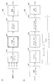
- FIG. 1 is a block diagram showing the configuration of a transmitter including a general bit-interleaved coding and modulation (BICM) encoder.
- the transmitter 100 shown in FIG. 1 comprises an input processing unit 110, a BICM encoder (including a low-density parity check (LDPC) encoder 120, a bit interleaver 130, a constellation mapper 140), and a modulator 150.
- a BICM encoder including a low-density parity check (LDPC) encoder 120, a bit interleaver 130, a constellation mapper 140
- LDPC low-density parity check
- the input processing unit 110 converts the input bit stream into multiple blocks of a predetermined length.
- the LDPC encoder 120 encodes the block into a codeword using an LDPC code and transmits the codeword to the bit interleaver 130.
- the bit interleaver 130 interleaves the LDPC code word, performs interleaving processing, and then divides it into a cell word (constellation word) sequence.
- Constellation mapper 140 maps each cell word (constellation word) to a sequence of constellations (eg, QAM).
- a general modulator 150 at the output end includes all processing blocks from the output of the BICM encoder to a Radio Frequency (RF) power amplifier.
- RF Radio Frequency
- An LDPC code is a linear error correction code which is completely defined by a parity check matrix (PCM).
- PCM is a binary sparse matrix and indicates a connection of codeword bits (also referred to as variable node) and parity check (also referred to as check node).
- the PCM columns and rows correspond to variable nodes and check nodes, respectively.
- the combination of the variable node and the check node is indicated by an element "1" in the PCM.
- the QC LDPC code has a configuration particularly suitable for hardware implementation. In fact, QC LDPC codes are used in most of today's standards.
- the PCM of the QC LDPC code has a special configuration having a plurality of cyclic matrices.
- a circulant matrix is a square matrix in which each row is in the form of one cyclic shift of elements in the row immediately before it, and one, two, or more folded diagonal columns May exist.
- the size of each circulant matrix is Q ⁇ Q.
- Q is referred to as a cyclic factor of the QC LDPC code.
- the pseudo-cyclic structure as described above allows Q check nodes to be processed in parallel, and QC LDPC codes are clearly advantageous codes for efficient hardware implementation.
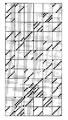
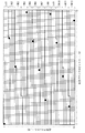
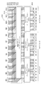
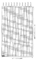
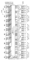
- one of the smallest squares represents one element of the PCM, and of these, the black square elements are “1”, and the other elements are “0”. It is.
- This PCM has a circulant matrix with one or two superimposed diagonal columns.
- the codeword bits are divided into blocks with Q bits.
- a block of cyclic coefficient Q bits is referred to herein as a cyclic block (or cyclic group).
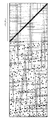
- RA QC LDPC repeat-accumulate quasi-cyclic low-density parity check
- RA QC LDPC codes are known for their ease of coding and are adopted in a number of standards (eg, second generation DVB standards such as DVB-S2 standard, DVB-T2 standard, DVB-C2 standard) There is.
- the right side of the PCM corresponds to a parity bit, and the arrangement of the “1” element in that portion has a step structure.
- FIG. 3 exemplifies the PCM of the RA QC LDPC code whose coding rate is 2/3.
- DVB-T stands for Digital Video Broadcasting-Terrestrial
- DVB-S2 stands for Digital Video Broadcasting-Second Generation Satellite
- DVB-T2 stands for Digital Video Broadcasting-Second Generation Terrestrial
- DVB- C2 is an abbreviation of Digital Video Broadcasting-Second Generation Cable.
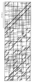
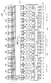
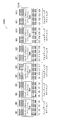
- the parity part of the PCM By performing appropriate permutation to change the order of bits only to the parity bits of the PCM shown in FIG. 4 subjected to the row permutation, the parity part of the PCM also has a pseudo cyclic structure.
- This technique is well known in the art, and is used under the name of parity interleaving or parity permutation in the DVB-T2 standard or the like.
- the PCM obtained as a result of applying parity permutation to the PCM shown in FIG. 4 is shown in FIG.
- LDPC codewords differ in significance from bit to bit, and constellations differ in robustness from bit to bit. Mapping the bits of the LDPC codeword directly to the constellation, ie without interleaving, does not lead to optimum performance. For this reason, the bits of the LDPC code word need to be interleaved before mapping the bits of the LDPC code word to the constellation.
- a bit interleaver 130 is provided between the LDPC encoder 120 and the constellation mapper 140. Careful design of the bit interleaver 130 improves the relevancy between bits of the LDPC codeword and bits encoded by the constellation, leading to improved reception performance. Its performance is usually measured using Bit Error Rate (BER) as a function of Signal to Noise Ratio (SNR).
- BER Bit Error Rate
- SNR Signal to Noise Ratio
- a complex quadrature amplitude modulation (QAM) constellation consists of two independent pulse amplitude modulation (PAM) symbols, one corresponding to the real part and one to the imaginary part. It corresponds.
- the two PAM symbols each encode the same number M of bits.
- FIG. 6 which shows 8 PAM symbols using Gray codes
- the robustness levels of the bits encoded in one PAM symbol are different from each other.
- the reason why the robustness levels are different from one another is that the distance between two subsets defined by each bit (0 or 1) is different for each bit. The larger this distance, the higher the robustness level or reliability of the bit.
- the robust level of bit b3 is the highest and the robust level of bit b1 is the lowest.
- a 16 QAM constellation encodes 4 bits and has 2 robust levels.
- the 64 QAM constellation encodes 6 bits and has 3 robust levels.
- a 256 QAM constellation encodes 8 bits and has 4 robust levels.
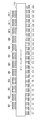
- FIG. 7 is a block diagram showing the configuration of a general interleaver corresponding to the above parameters.
- QB1, ..., QB12 are 12 cyclic blocks
- C1, ..., C24 are 24 constellation words.
- bit interleaver 710 interleaves the 96 bits of the LDPC codeword.
- DVB-T2 As a conventional bit interleaver, one of the DVB-T2 standard (ETSI EN 302 755) is known.
- the DVB-T2 standard is an improvement on the DVB-T standard which is a television standard, and describes a second generation baseline transmission system for digital terrestrial television broadcasting.
- the DVB-T2 standard details channel coding modulation systems for transmitting digital television services and general data.
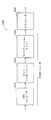
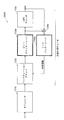
- FIG. 8A is a block diagram showing the configuration of a modulator (DVB-T2 modulator) used in the DVB-T2 standard.
- the DVB-T2 modulator 800 shown in FIG. 8 (a) comprises an input processing unit 810, a BICM encoder 820, a frame builder 830 and an OFDM generator 840.
- the input processing unit 810 converts the input bit stream into blocks of a predetermined length.
- the BICM encoder 820 performs BICM processing on the input.
- the frame builder 830 generates a DVB-T2 transmission frame configuration using inputs from the BICM encoder 820 and the like.
- the OFDM generator 840 performs pilot addition, high-speed inverse Fourier transform, guard interval insertion, and the like on the transmission frame configuration of the DVB-T2 system, and outputs a transmission signal of the DVB-T2 system.
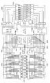
- FIG. 8B is a block diagram showing the configuration of the BICM encoder 820 of the DVB-T2 modulator shown in FIG. 8A. However, in FIG. 8B, BCH outer coding, constellation rotation, cell interleaver, time interleaver and the like are omitted.
- the BICM encoder 820 includes an LDPC encoder 821, a bit interleaver (including a parity interleaver 822 and a column-row interleaver 823), a bit-cell demultiplexer 824, and a QAM mapper 825.
- the LDPC encoder 821 encodes a block into a codeword using an LDPC code.
- the bit interleaver (parity interleaver 822 and column-row interleaver 823) performs interleaving processing to change the order of the bits of the code word.
- the bit-cell demultiplexer 824 demultiplexes the interleaved codeword bits into cell words (constellation words).
- the QAM mapper 825 maps cell words (constellation words) to complex QAM symbols.
- the complex QAM symbol is also referred to as a cell.
- the bit-cell demultiplexer 824 may be considered to be part of a bit interleaver.
- a BICM encoder based on the DVB-T2 standard can be regarded as having the standard configuration shown in FIG.
- two codewords of 16200 bits and 64800 bits are defined.
- An LDPC code having a codeword length of 16200 bits and an LDPC code having a codeword length of 64800 bits are referred to herein as a 16K code (or 16K LDPC code) and a 64K code (or 64K LDPC code).
- the number of cyclic blocks included in one code word is 45 for the 16K code and 180 for the 64K code.
- the usable codes corresponding to these two block lengths (code word lengths) are listed in Table A.1 of ETSI EN 302 755, which is a DVB-T2 standard. 1 to Table A. 6 listed.
- the bit interleaver is used only for constellations larger than QPSK and comprises a parity interleaver 822, a column-row interleaver 823 and a bit-cell demultiplexer 824. Note that, in the definition of the DVB-T2 standard, the bit-cell demultiplexer 824 is not included in the bit interleaver. However, since the present invention relates to interleaving applied to an LDPC code before constellation mapping, the bit-cell demultiplexer 824 is also treated as part of bit interleaving.
- the parity interleaver 822 performs parity permutation to change the order of parity bits of the codeword in order to clarify the pseudo-cyclic structure of parity bits.
- the column-row interleaver 823 works conceptually by writing the bits of the LDPC codeword along the columns of the interleaver matrix and reading them along the rows. The first bit contained in the LDPC code word is written first and read first. The column-row interleaver 823 shifts the bits cyclically by a predetermined number of positions with respect to the column after writing the bits of the LDPC code word and before starting reading the bits. This is called column twisting in the DVB-T2 standard. The number of columns Nc and the number of rows Nr of the interleaver matrix corresponding to the above two LDPC codeword lengths and various constellation sizes are shown in Table 1 below.
- the number of columns Nc is twice the number of bits of one constellation, except in the case of a 16K code in a 256 QAM constellation.
- the reason for this exception is that the LDPC codeword length of 16200 is not a multiple of 16, ie twice the number of bits in the 256 QAM constellation.
- bit-cell demultiplexer 824 demultiplexes each LDPC codeword to obtain multiple parallel bit streams.
- the number of streams is twice that of the number M of bits encoded in one QAM constellation, ie 2 ⁇ M, except in the case of a 16K LDPC code in a 256 QAM constellation.
- the number of streams is M, the number of bits encoded in one QAM constellation.
- M bits encoded in one constellation are referred to as cell words (or constellation words). As described below, in a 16K LDPC code, the number of cell words obtained from one code word is 16200 / M.
- the bit-cell demultiplexer comprises a simple demultiplexer 1110 (1210, 1310) and a demultiplexing permutation unit 1120 (1220, 1320), as shown in FIG. 11 (FIGS. 12, 13).
- bit-cell demultiplexer in addition to simply demultiplexing the interleaved LDPC codeword by the simple demultiplexer 1110 (1210, 1310), by the demultiplexing unit 1120 (1220, 1220) Permutation processing is performed on the demultiplexed parallel bit stream to change its order.
- bit interleaver used in the DVB-T2 standard comes with two problems.
- the first problem is that parallelism is lost when the number of cyclic blocks in an LDPC codeword is not a multiple of the number of columns of the bit interleaver matrix. Latency increases as parallelism decreases. This is particularly a problem when iterative BICM decoding is used at the receiver. This situation occurs with some of the combinations of LDPC codeword length and constellation size for the DVB-T2 standard.
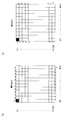
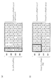
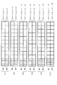
- FIGS. 14 and 15 are diagrams showing the above-mentioned situation which occurs when the number of columns of the interleaver matrix is 8 and 12, respectively, in the 16K LDPC code.
- 16 QAM and 256 QAM constellations an 8-row interleaver matrix is used.
- 64 QAM constellation a 12-column interleaver matrix is used.
- a grid represents an LDPC code word
- a small square represents one bit of the LDPC code word
- a row corresponds to a cyclic block
- a column corresponds to a bit having the same bit index as each other in a plurality of cyclic blocks.
- Filled squares represent 8 bits and 12 bits in the first row of the interleaver matrix.
- the second problem is that in the DVB-T2 standard, the number of possible bit interleaver configurations is limited by the number of columns of the bit interleaver matrix.
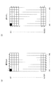
- FIGS. 16 and 17 show the same situation as in FIGS. 14 and 15, respectively, except that column twist processing is applied.
- the column twist value for each column used in the DVB-T 2-bit interleaver is (0, 0, 0, 1, 7, 20, 20, 21).
- the column twist value for each column used in the DVB-T 2-bit interleaver is (0, 0, 0, 2, 2, 2, 3, 3, 3, 6, 7, 7).
- Embodiment (Part 1) ⁇ Embodiment (Part 1) >>
- bit interleaver parallel bit interleaver
- the same reference numerals are given to constituent units that perform substantially the same processing content and the same processing content.
- each of a group of M cyclic blocks or each of a group of Q constellation words is called a section (or an interleaver section).
- It is a block diagram which shows one structural example of a figure and the said bit interleaver.
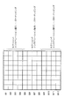
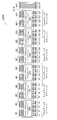
- the section permutation units (2021, 2022, 2023) are independent of each other (independently of each other), and each of eight constellation words (C1 to C8, C9 to C16, C17 to C24) is 4 Section per order to change the order of a total of 32 bits of 4 cyclic blocks so that 1 bit is mapped from each of 2 cyclic blocks (QB1 to QB4, QB5 to QB8, QB9 to QB12) Perform a mutation process.
- the two conditions 1 and 2 described above are merely to ensure that the bit interleaver is divided into N / M parallel sections.
- the same permutation rule may be applied to the section permutation processing applied to these parallel sections, or different permutation rules may be applied, or only some of them may be identical to each other. Mutation rules may be applied.
- the section permutation unit maps Q bits of a cyclic block (equal in importance in the LDPC decoding process) to bits of the same bit index of Q constellation words (robust levels are equal to one another). You may do it.
- the Q bits can be arranged sequentially or in permutation order. The latter will be described using FIGS. 21 (a) and 21 (b) and the former using FIGS. 22 (a) and 22 (b).
- FIG. 21A shows an example of the configuration of the section permutation unit shown in FIG.
- Section permutation unit 2101 includes intra-cyclic block permutation units 2111-2114 and column-row permutation unit 2131. It should be noted that instead of providing four intra-cyclic block permutation units, for example, four intra-cyclic block permutations to be described later while switching processing targets in time series using one intra-cyclic block permutation unit. Processing may be performed.
- the intra-cyclic block permutation unit (2111 to 2114) performs intra-cyclic block permutation processing for changing the order of the Q (8) bits of the cyclic blocks (QB1 to QB4).
- the same permutation rule may be applied to the intra-cyclic block permutation processing applied to cyclic blocks in one section, or different permutation rules may be applied. Only part of the permutation rules may be applied to each other.
- the column-row permutation unit 2131 performs column-row permutation processing to change the order of M ⁇ Q (32) bits. Specifically, the column-row permutation unit 2131 writes M ⁇ Q (32 bits) in the row direction of a matrix of Q columns and M rows (8 columns and 4 rows), and writes M ⁇ Q pieces Column-row permutation processing equivalent to reading (32) bits in the column direction is performed. In the column-row permutation processing by the column-row permutation unit 2131, the 12th row 1350 rows in FIGS. 9A and 9B are replaced with the Q row M row, and the write processing is from the column direction to the row direction In addition, the reading process is changed from the row direction to the column direction.
- FIG. 21 (b) is a view showing the function of mapping by the section permutation unit of FIG. 21 (a).
- M 4 bits of each constellation word are indicated by b1 to b4.
- intra-cyclic block permutation processing may not be performed in the section permutation processing.
- FIG. 22 (b) Another example of the section permutation in FIG. 20, one configuration example of the section permutation unit not carrying out the intra-cyclic block permutation processing and the function of the mapping by this section permutation unit are shown in FIG. And FIG. 22 (b).
- the section permutation unit 2201 has a column-row permutation unit 2131 and performs only column-row permutation processing.
- M 4 bits of each constellation word are indicated by b1 to b4.
- section permutation described in FIGS. 21 and 22 may be performed on cyclic blocks QB5 to QB8 and QB9 to QB12.
- the bit interleaver additionally performs cyclic block permutation processing to rearrange the order of N cyclic blocks before performing section permutation processing.
- One configuration example of a bit interleaver that additionally performs cyclic block permutation processing is shown in FIG.
- the cyclic block permutation here plays the same role as the permutation by the bit-cell demultiplexer in the DVB-T2 standard.
- the bit interleaver 2300 shown in FIG. 23 includes a cyclic block permutation unit 2310 and a bit permutation unit 2010 (including section permutation units 2021 to 2023).
- the cyclic block permutation unit 2310 performs cyclic block permutation processing 2311 to 2318 for changing the order of the cyclic blocks QB1 to QB12. Note that permutation rules used in cyclic block permutation processing 2311 to 2318 are the same as one another.
- Cyclic block permutation applied to N cyclic blocks is particularly useful because it enables optimal mapping of bits of an LDPC codeword to bits of a constellation, leading to optimization of reception performance. is there.
- FIG. 24 is a block diagram showing one configuration example of the bit interleaver of FIG.
- the bit interleaver 2400 of FIG. 24 performs the following three permutation processes of stages A, B and C.
- Stage A cyclic block (inter) permutation
- Stage B intra-cyclic block permutation
- Stage C column-row permutation
- the cyclic block (inter) permutation is N cycles constituting a codeword Permutation to change the order of blocks
- in-block permutation is permutation to change the order of Q bits that make up a cyclic block
- column-row permutation forms sections It is a permutation that changes the order of M ⁇ Q bits to be processed.
- the bit interleaver 2400 shown in FIG. 24 includes a cyclic block permutation unit 2310 and a bit permutation unit 2010 (section permutation units 2101 to 2103).
- the section permutation unit 2101 (2102, 2103) includes intra-cyclic block permutation units 2111 to 2114 (2115 to 2118, 2119 to 2122) and column-row permutation units 2131 (2132, 2133).
- the bit interleaver 2400 performs cyclic block (interleave) permutation by the cyclic block permutation unit 2310 (stage A), and performs intra cyclic block permutation by the intra cyclic block permutation units 2111 to 2122 (stage B) Column-row permutation is performed by column-row permutation units 2131 to 2133) (stage C).
- the intra-cyclic block permutation units 2111 to 2122 may be removed from the bit interleaver shown in FIG. 24 so that the intra-cyclic block permutation is not performed. Also, the bit interleaver may perform intra-cyclic block permutations before cyclic block (inter) block permutations instead of performing after cyclic block (inter-block) permutations; Between) may be performed before and after the permutation.
- the plurality of intra-cyclic block permutation units may have the same configuration. Therefore, a plurality of intra-cyclic block permutation units can be implemented by the same functional resource (such as a hardware block). Also, the plurality of intra-cyclic block permutations may consist of cyclic shift processing, in which case efficient hardware implementation using a barrel shifter is possible. It is also possible to implement using the barrel shifter used for the LDPC decoder.
- FIG. 25 is a block diagram showing an exemplary configuration of a transmitter according to still another embodiment of the present invention.
- the transmitter 2500 shown in FIG. 25 includes a BICM encoder (including an LDPC encoder 2510, a bit interleaver 2520, and a constellation mapper 2530) and a modulator 2540.
- the LDPC encoder 2510 encodes the input block into a codeword using a QC-LDPC code, and outputs the codeword to the bit interleaver 2520.
- bit interleaver 2520 additionally performs cyclic block permutation processing described, for example, in FIGS. 23 to 24 or as a modification thereof in addition to bit permutation processing as bit interleaving processing. May be
- Constellation mapper 2530 receives a constellation word from bit interleaver 2520 and performs constellation mapping processing on the received constellation word.
- the modulator 2740 performs orthogonal frequency division multiplexing (OFDM) modulation or the like to generate a transmission signal.
- OFDM orthogonal frequency division multiplexing
- FIG. 26 is a block diagram showing an implementation example of a BICM encoder according to still another embodiment of the present invention.
- the BICM encoder 2600 shown in FIG. 26 includes a main memory 2601, an LDPC controller 2611, a rotator 2612, a check node processor group 2613, a derotator 2614, a QB counter 2631, a table 2632, an interleaver 2633, a register group 2634, an interleaver 2635, and a mapper.
- a group 2651 is provided.
- the main memory 2601 receives a bit string to be transmitted, for example, from an input processing unit (not shown), and holds the received bit string.
- the LDPC controller 2611 outputs a read address to the main memory 2601, whereby the main memory 2601 outputs eight bits from the beginning of the bit string to the rotator 2612.
- the rotator 2612 cyclically shifts the predetermined number of 8 bits supplied from the main memory 2601 under the control of the LDPC controller 2611, and shifts the eight bits after cyclic shift to each check node processor of the check node processor group 2613. Output bit by bit.
- Each check node processor of each check node processor group 2613 performs check node processing on the input 1 bit under the control of the LDPC controller 2611, and outputs the 1 bit processing result to the derotator 2614.
- Derotator 2614 cyclically shifts the eight bits received from check node processor group 2613 a predetermined number so as to cancel the cyclic shift by rotator 2612 under the control of LDPC controller 2611, and sends the eight bits after cyclic shift to main memory 2601. Output.
- the LDPC controller 2611 outputs a write address to the main memory 2601, whereby the main memory 2601 holds 8 bits supplied from the derotator 2614.
- the LDPC controller 2611, the rotator 2612, the check node processor group 2613, and the derotator 2614 constitute an LDPC encoder 2510 of the BICM encoder in FIG.
- the QB counter 2631 counts from 0 to 11, and outputs the counter value to the table 2632.
- the read address is output.
- the main memory 2601 outputs, to the interleaver 2633, bits for one cyclic block corresponding to the counter value of the QB counter 2631.
- the cyclic block permutation (stage A) is realized by the processing of this table 2632.
- the interleaver 2633 cyclically shifts the bits for one cyclic block supplied from the main memory 2601 by a predetermined number and outputs the result to the first stage register of the register group 2634.
- intra-cyclic block permutation stage B is realized by the processing of the interleaver 2633.
- each register of the register group 2634 holds the bits for one cyclic block at the timing when the control pulse is received, and continues to output the held bits for one cyclic block until the control pulse is next received.
- the bits (32 bits) for 4 cyclic blocks are input to the interleaver 2635.
- M 4 bits
- the QB counter 2631, the table 2632, the interleaver 2633, the register group 2634, and the interleaver 2635 constitute a bit interleaver 2520 of the BICM encoder in FIG.
- mapper group 2651 maps the 4 bits supplied from the interleaver 2635 into a constellation, and outputs the mapping result.
- mapper group 2651 constitutes constellation mapper 2530 of the BICM encoder in FIG.
- the above series of processing is performed three times for one code word, in total, from the counter values “0” to “3”, “4” to “7”, and “8” to “11” of the QB counter 2631.
- FIG. 26 includes Q mappers operating in parallel
- Q mappers operating in parallel
- the parallelism can be easily increased by increasing the number of parallel interleaver sections in the bit interleaver, ie N / M.
- parallelization can be maximized by parallelizing Q ⁇ N / M mappers.
- Bit interleavers have the advantage that such parallelism can be realized without any obstacles.
- FIG. 27 is a block diagram showing an example configuration of a receiver having a non-iterative BICM decoder according to still another embodiment of the present invention. The receiver operates in reverse to the transmitter.
- the receiver 2700 shown in FIG. 27 comprises a modulator 2710 and a non-iterative BICM decoder (including constellation demapper 2720 and bit deinterleaver 2730, LDPC decoder 2740).
- the demodulator 2710 performs demodulation processing using OFDM or the like, and outputs the demodulation processing result.
- Constellation demapper 2720 of the non-repetitive BICM decoder demaps the input from modulator 2710 to generate a so-called soft bit string, and outputs the generated soft bit string to constellation demapper 2730.
- Each soft bit is a measure of the probability that each bit will be 0 or 1.
- soft bits are represented by log likelihood ratios (LLRs) and defined as follows.
- the bit deinterleaver 2730 interleaves the soft bit sequence output from the constellation demapper 2720 by the bit interleaver in the transmitter of FIG. (Bit de-interleaving processing) is performed.
- the LDPC decoder 2740 receives the soft bit sequence subjected to bit deinterleaving from the bit deinterleaver 2730, and performs an LDPC decoding process using the received soft bit sequence.
- FIG. 28 is a block diagram showing an example of configuration of a receiver having an iterative BICM decoder according to still another embodiment of the present invention. The receiver operates in reverse to the transmitter.
- the receiver 2800 shown in FIG. 28 includes a modulator 2710 and an iterative BICM decoder (constellation demapper 2720, bit deinterleaver 2730, LDPC decoder 2740, subtraction unit 2760, bit interleaver 2750).
- BICM decoder castellation demapper 2720, bit deinterleaver 2730, LDPC decoder 2740, subtraction unit 2760, bit interleaver 2750.
- the receiver 2800 in FIG. 28 performs constellation demapping processing by the constellation demapper 2720, bit deinterleaving processing by the bit deinterleaving 2730, and LDPC decoding processing by the LDPC decoder 2740.
- a subtraction unit 2760 subtracts the input of the LDPC decoder 2740 from the output of the LDPC decoder 2740, and extrinsic information obtained as a result of the subtraction is bit interleaver Output to 2750.
- the bit interleaver 2750 performs interleaving on the external information in the same interleaving rule as the bit interleaving performed on the bit sequence by the bit interleaver in the transmitter of FIG. Then, bit interleaver 2750 feeds back the interleaved external information to constellation demapper 2720. Constellation demapper 2720 uses the fed-back external information as a-priori information to calculate a more reliable LLR value.
- bit deinterleaver 2730 cancels the bit interleaving processing applied to the bit string by the bit interleaver in the transmitter of FIG. 25 to the newly calculated LLR value and restores the original order (bit deinterleaver Interleave processing).
- the LDPC decoder 2740 performs an LDPC decoding process using the LLR value subjected to the bit deinterleaving process.
- the iterative decoding loop consists of four elements: constellation demapper 2720, bit deinterleaver 2730, LDPC decoder 2740, and bit interleaver 2750.
- the bit deinterleaver 2730 and the bit interleaver 2750 have very low latency, ideally zero, and a simple configuration allows efficient implementation of the receiver.
- the above-described bit deinterleaver 2730 and bit interleaver 2750 satisfy both conditions.
- FIG. 1 One implementation of the iterative BICM decoder that implements a very efficient parallel implementation is described using FIG.
- FIG. 29 is a block diagram showing an implementation example of a BICM decoder according to still another embodiment of the present invention.
- the BICM decoder 2900 shown in FIG. 29 includes a main LLR memory 2901, a buffer LLR memory 2902, an LDPC controller 2911, a rotator 2912, a check node processor group 2913, a derotator 2914, a QB counter 2931, a table 2932, a subtraction unit 2933, an interleaver 2934, A register group 2935, an interleaver 2936, a demapper group 2937, a deinterleaver 2938, a register group 2939, a deinterleaver 2940, and a delay unit 2941 are provided.
- demapper of the demapper group 2937 performs demapping processing using the output of the demodulator (not shown), and outputs the LLR value obtained thereby to the deinterleaver 2938.
- demapper group 2937 constitutes constellation demapper 2720 of the iterative BICM decoder in FIG.
- the deinterleaver 2938 performs deinterleaving processing (interleaving processing to cancel interleaving by the stage C by the transmitter) on the LLR value, and outputs the LLR value after deinterleaving to each register of the register group 2939.
- LLR values (eight LLR values) for one circulating block are stored in each of the registers.
- the LLR values for one cyclic block held in the registers are sequentially output to the subsequent stage, and the held contents of the respective registers are sequentially updated.
- the deinterleaver 2940 performs interleaving processing (interleaving processing to cancel interleaving by the stage B by the transmitter) on the LLR values (eight LLR values) for one cyclic block to be supplied, and stores the contents of the table 2932 ( The main LLR memory 2901 and the buffer LLR memory 2902 are written according to the following description). Note that, by writing to the main LLR memory 2901 and the buffer LLR memory 2902 in accordance with the contents held in the table 2932, interleaving processing to cancel interleaving by the stage A by the transmitter is realized.
- the main LLR memory 2901 stores the LLR value after the de-interleaving process, and is also used by the LDPC decoder (LDPC controller 2911, rotator 2912, check node processor group 2913, derotator 2914).
- the LDPC decoding process is an iterative process consisting of one or more iterations. At each iteration of the LDPC decoding process, the LLR values in the main LLR memory 2901 are updated. The old LLR values are held in the buffer LLR memory 2902 to calculate the extrinsic information needed for the iterative BICM decoding process.
- the LDPC controller 2911 outputs the read address to the main LLR memory 2901 according to the parity check matrix of the LDPC code, whereby the main LLR memory 2901 sequentially outputs LLR values to the rotator 2912 for each one of the cyclic blocks.
- the rotator 2912 cyclically shifts the LLR values for one cyclic block sequentially supplied from the main LLR memory 2901 by a predetermined number under the control of the LDPC controller 2911, and the LLR values after cyclic shift are of the check node processor group 2913. Output one by one to each check node processor.
- Each check node processor of each check node processor group 2913 performs check node processing on a series of LLR values sequentially input under control of the LDPC controller 2911.
- each check node processor of the check node processor group 2913 receives control of the LDPC controller 2911 and sequentially outputs a series of LLR values as a result of check node processing.
- the derotator 2914 cyclically shifts the processing result for one cyclic block sequentially received from the check node processor group 2913 by a predetermined number so as to cancel the cyclic shift by the rotator 2912 under the control of the LDPC controller 2911 and cyclic shift
- the processing results are sequentially output to the main LLR memory 2901.
- the LDPC controller 2911 outputs a write address to the main LLR memory 2901 according to the parity check matrix of the LDPC code, whereby the main LLR memory 2901 holds the processing result for one cyclic block sequentially supplied from the derotator 2914. .
- the LDPC controller 2911 repeatedly executes the above processing in accordance with the parity check matrix of the LDPC code.
- BICM iterations are performed.
- LDPC and BICM iterative processes are also referred to as internal and external iterative processes, respectively.
- the BICM and LDPC decoding processes are well known in the art and will not be described in detail.
- the QB counter 2931 counts from 0 to 11, and outputs the counter value to the table 2932.
- the main LLR memory 2901 is supplied so that LLR values for one cyclic block corresponding to the counter value supplied from the QB counter 2931 are supplied from the main LLR memory 2901 and the buffer LLR memory 2902 to the subtraction unit group 2933. And outputs the read address to the buffer LLR memory 2902.
- main LLR memory 2901 and buffer LLR memory 2902 each output LLR values for one cyclic block corresponding to the counter value of QB counter 2931 to subtraction unit 2934.
- the delay position by the delay unit 2941 is set so that the reading position of the LLR value from the main LLR memory 2901 and the buffer LLR memory 2902 and the writing position of the LLR value to the main LLR memory 2901 and the buffer LLR memory 2902 coincide with each other. Adjustments will be made. Note that the permutation corresponding to the cyclic block permutation (stage A) is realized by the processing of the table 2932.
- Each subtraction unit 2933 of the subtraction unit group subtracts the output of the buffer LLR memory 2902 from the output of the main LLR memory 2901 and obtains external information (eight external information) for one cyclic block obtained as a result of subtraction. Output to interleaver 2934.
- the interleaver 2934 cyclically shifts the external information for one cyclic block supplied from the subtraction unit 2933 by a predetermined number and outputs the information to the first stage register of the register group 2935.
- the processing corresponding to the intra-cyclic block permutation (stage B) is realized by the processing of the interleaver 2934.
- each register of the register group 2935 receives a control pulse and holds 8 bits, and keeps holding the held 8 bits until the next control pulse is received.
- the interleaver 2936 receives external information (32 external information) for 4 cyclic blocks. .
- M 4 for each demapper of the demapper group 2937
- the QB counter 2931, the table 2932, the interleaver 2934, the register group 2935, and the interleaver 2936 constitute a bit interleaver 2750 of the BICM decoder in FIG.
- Each demapper of the demapper group 2937 performs demapping processing using the four pieces of external information supplied from the interleaver 2936 as prior information, and outputs a new LLR value to the deinterleaver 2938.
- the deinterleaver 2938 performs deinterleaving processing (interleaving processing to cancel interleaving by the stage C by the transmitter) on the LLR value, and outputs the LLR value after deinterleaving to each register of the register group 2939.
- LLR values (eight LLR values) for one circulating block are stored in each of the registers.
- the LLR values for one cyclic block held in the registers are sequentially output to the subsequent stage, and the held contents of the respective registers are sequentially updated.
- the deinterleaver 2940 performs deinterleaving processing (interleaving processing to cancel interleaving by the stage B by the transmitter) on the LLR values (eight LLR values) for one cyclic block to be supplied, and the main LLR memory 2901 and Output to buffer LLR memory 2902.
- the main LLR memory 2901 and the buffer LLR memory 2902 receive the write address from the table 2932 via the delay unit 2941, and according to the received write address, the LLR values for one cyclic block received from the deinterleaver 2940 (eight Hold LLR value).
- the write processing according to the table 2932 realizes interleaving processing (de-interleaving processing) that cancels interleaving by the stage A by the transmitter.
- the above series of processing is performed three times for one code word, in total, from the counter values “0” to “3”, “4” to “7”, and “8” to “11” of the QB counter 2931.
- the QB counter 2931, the table 2932, the deinterleaver 2938, the register group 2939, and the deinterleaver 2940 constitute a bit deinterleaver 2730 of the BICM decoder in FIG. 28.
- Interleaver 2934 and de-interleaver 2940 are reconfigurable and have a constant hardware cost, but the cost can be minimized by careful design.
- Interleaver 2936 and de-interleaver 2938 implement column-row permutation, which is constant for a given constellation size. Therefore, the implementation cost is small.
- FIG. 29 includes Q demappers operating in parallel
- the parallelism can be easily increased by increasing the number of parallel interleaver sections in the bit interleaver, ie N / M.
- parallelization can be maximized by parallelizing Q ⁇ N / M demappers.
- the bit interleaver described above has the advantage that such parallelism can be realized without any obstacles.
- the bit interleaver selects N 'cyclic blocks that are multiples of the number M of bits of the constellation word among the N cyclic blocks.
- the bit interleaver divides the selected N 'cyclic blocks into N' / M sections such that each contains M cyclic blocks, and performs section permutation on each section.
- the bits of the excluded (not selected) cyclic block may not be interleaved or may be interleaved.
- the excluded cyclic block may be the one with the smallest variable node weight.
- the excluded cyclic block may be a cyclic block of the parity part (having a variable node of weight 2), in this case, for example, from the end of the codeword It may be one or more cyclic blocks.
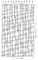
- FIG. 30 is a diagram illustrating a cyclic block to which the interleaving method described in the embodiment is applied (the cyclic block to be excluded) and a cyclic block to which the interleaving method is applied is not applied.
- FIG. 30 is a diagram for the case where the code is a 16K LDPC code defined in the DVB-T2 standard and the constellation is a 16 QAM constellation.
- the cyclic block to be applied is 44 cyclic blocks (1,..., 44), and the cyclic blocks not to be applied (cyclic blocks to be excluded) are one in the last row. This is only the cyclic block 45.
- four black squares represent four bits of the first constellation word.
- the number of interleaver sections is floor (N / M), and the number of cyclic blocks excluded is rem (N, M).
- floor (N / M) is a function that returns the largest integer value of N / M or less
- rem (N, M) is a function that returns a remainder value obtained by dividing N by M.
- each constellation word is mapped to M cyclic blocks.
- a very large number of delay registers are required (FIGS. 26 and 29). See the implementation example described in The use of very large delay registers leads to increased circuit area and power consumption.
- reducing the number of cyclic blocks to which the constellation word is mapped is beneficial to increase the overlap between the outer (BICM) and inner (LDPC) iterations, and the overall BICM Reduce decoding latency.
- the number of cyclic blocks to which the constellation word is mapped can be reduced.
- the number of bits of the constellation word mapped to the same cyclic block is referred to as a folding coefficient and denoted as F.
- F the folding coefficient
- the constellation word is mapped to only 2 cyclic blocks instead of 4 cyclic blocks.
- Complex QAM constellation symbols can be separated into two equal real pulse-amplitude modulation (PAM) symbols.
- PAM pulse-amplitude modulation
- the M bits of the QAM constellation can be divided into a set of M / 2 bits of two equal real PAM symbols, and the bits of the constellation word can be mapped to the same M / 2 cyclic blocks .
- Folding has the added benefit of reducing the number of excluded cyclic blocks or zeroing out the number of excluded cyclic blocks.
- the inventor has found that it is necessary to change the conditions 1 and 2 to the following conditions 1A and 2A in order to perform folding (F is an integer of 2 or more).
- F 1 means no folding, and conditions 1A and 2A are the same as conditions 1 and 2.
- each of a group of M / F cyclic blocks or each of a group of Q / F constellation words is referred to as a folding section (or a folding interleaver section).
- the folding interleaver section matches the interleaver section, and the bit interleaver has the same configuration as the bit interleaver of the embodiment (part 1).
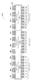
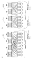
- the folding section permutation units (2021A, 2022A, 2023A, 2024A, 2025A, 2026A) are independent of one another (independently of one another) and four constellation words (C1-C4, C5-C8, C9).
- M / F 2 cyclic blocks (QB1 to QB2, QB3 to QB4, QB5 to QB6, QB7 to QB8, QB9 to QB10, QB11) for each of C12 to C12, C13 to C16, C17 to C20, and C21 to C24).
- the above two conditions 1A and 2A are merely to ensure that the bit interleaver is divided into F ⁇ N / M parallel folding sections.
- the same permutation rules may be applied to the folding section permutation processing applied to these parallel folding sections, or different permutation rules may be applied, or only some of them may be applied.
- the same permutation rules may be applied to each other.
- the constellation is a 16 QAM constellation. Therefore, there are two robust levels in the bits of the constellation, and the bits b1 and b3 are the same robust level, and the bits b2 and b4 are the same robust level.
- the folding section permutation unit 2201A (2202A) has a column-row permutation unit 2131A (2132A).
- folding of the folding coefficient F reduces the number of cyclic blocks mapped to one constellation word. This reduces the number of matrix rows in column-row permutation from M to M / F.
- FIG.33 (a) is a figure which shows the function of the mapping by the (folding) section permutation unit of Fig.34 (a)
- FIG.33 (b) is two folding sections of FIG.34 (a). It is a figure which shows the function of the mapping by a permutation unit.
- M 4 bits of each constellation word are indicated by b1 to b4.
- the portions surrounded by thick lines represent the mapping for the constellation word C1.
- eight bits (having the same importance) of one cyclic block are bits having the same bit index of eight constellation words (having the same robustness level). Is mapped to). Also, in the example of FIGS. 33 (b) and 34 (b), 8 bits (having the same importance) of one cyclic block are mapped to bits of the same robust level of 4 constellation words. .
- folding section permutation described in FIG. 34B may be performed on the cyclic blocks QB5 to QB6, QB7 to QB8, QB9 to QB10, and QB11 to QB12.
- the bit interleaver performs cyclic block permutation processing to additionally change the order of N cyclic blocks before performing folding section permutation processing. I do.
- An exemplary configuration of a bit interleaver that additionally performs cyclic block permutation processing is shown in FIG.
- the bit interleaver 2300A shown in FIG. 35 includes a cyclic block permutation unit 2310 and a bit permutation unit 2010A (including folding section permutation units 2021A to 2026A).
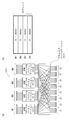
- FIG. 36 is a block diagram showing a configuration example of the bit interleaver of FIG.
- Bit interleaver 2400A in FIG. 36 includes cyclic block permutation unit 2310 and bit permutation unit 2200A (including folding section permutation units 2201A to 2206A).
- the folding section permutation units 2201A to 2206A respectively include column-row permutation units 2131A to 2136A.
- the column-row permutation units 2133A to 2136A perform substantially the same permutation processing as the column-row permutation units 2133A to 2132A.
- a unit performing permutation in a cyclic block to change the order of bits in cyclic blocks QB1 to QB12 is added to the previous or subsequent stage of cyclic block permutation. May be
- FIG. 37 is a block diagram showing an exemplary configuration of a transmitter according to still another embodiment of the present invention.
- Transmitter 2500A shown in FIG. 37 has a configuration in which bit interleaver 2520 of transmitter 2500 in FIG. 25 is replaced with bit interleaver 2520A.
- FIG. 38 is a block diagram showing an example of configuration of a receiver having a non-iterative BICM decoder according to still another embodiment of the present invention.
- the receiver operates in reverse to the transmitter.
- Receiver 2700A shown in FIG. 38 has a configuration in which bit deinterleaver 2730 of receiver 2700 in FIG. 27 is replaced with bit deinterleaver 2730A.
- the bit deinterleaver 2730A cancels the bit interleaving processing applied to the bit string by the bit interleaver 2520A in the transmitter 2500A to the soft bit string output from the constellation demapper 2720 to restore the original assortment ( Perform bit de-interleaving processing).
- FIG. 39 is a block diagram showing an example of configuration of a receiver having a non-iterative BICM decoder according to still another embodiment of the present invention.
- the receiver operates in reverse to the transmitter.
- Receiver 2800A shown in FIG. 39 has a configuration in which bit deinterleaver 2730 and bit interleaver 2750 of receiver 2800 in FIG. 28 are replaced with bit deinterleaver 2730A and bit deinterleaver 2750A.
- Bit interleaver 2750A performs interleaving on the external information (extrinsic information) in the same interleaving rule as bit interleaving performed on bit strings by bit interleaver 2520A in transmitter 2500A.
- folding may be such that bits of one constellation word are placed in fewer LLR memory locations.
- the LLR memory in the decoder has G ⁇ N addressable locations, each location being capable of holding Q / G LLR values.
- G is an implementation parameter that is a divisor of Q and is referred to as memory granularity.
- the number of LLR values in the memory location ie Q / G, needs to be a multiple of F, and the LLR values of each constellation are stored at the same location in all locations of memory. This ensures that LLR values in any constellation word are stored in M / F memory locations.
- the LLR values of the second and fifth constellation words are held in four memory locations instead of two memory locations.
- folding is very useful when two or more constellation symbols are jointly decoded.
- Joint decoding is required, for example, for maximum likelihood decoding of block codes (space-time codes, frequency-space codes, etc.) or rotational constellations of two or more dimensions.
- a block code encodes two or more input symbols (x 1 ,..., X K ) into two or more output symbols (y 1 ,..., Y L ).
- L is less than or equal to K.
- the block code is modeled by an L-by-K generator matrix.
- the elements of the input signal vector X and the output signal vector Y can be real or complex numbers.
- the output signal vector Y may be transmitted in different time slots or different frequency slots, transmitted using different antennas, or transmitted using different time slots or different frequency slots and different antennas There is.
- Block codes for multiple-input multiple-output (MIMO) communication systems include Alamouti code, Golden code, and spatial multiplexing.
- the folding coefficients can be used up to K if K symbols are encoded in the same block. Furthermore, if the symbol is a QAM symbol (including two separable PAM symbols), the usable folding factor may be increased to 2 ⁇ K.
- the two constellations have different robustness levels from each other. For example, the cyclic block mapped to the bit of one constellation word and the cyclic block mapped to the bit of the other constellation word are made to be different from each other.
- a code space multiplexing MIMO system using two transmit antennas will be described as an example.
- X [x 1 x 2 ] be the complex signal before encoding.
- x 1 is a signal subjected to QPSK
- x 2 is a signal subjected to 16 QAM.
- y 1 and y 2 are signals transmitted by the first antenna and the second antenna, respectively.
- FIG. 41 shows only the first seven bits in the cyclic block.
- the two complex symbols x 1 and x 2 have the following structure:
- x 1 is a QPSK symbol given by the real part b 1 and the imaginary part b 2.
- x 2 is the real part is b3, b4, a 16QAM symbol imaginary part is given by b5, b6.
- the two symbols are jointly decoded at the receiver, thereby creating a so-called constellation block or a generated block.
- the entire 6-bit constellation block will have 3 robust levels.
- Level 1 b1 and b2 of QPSK are mapped to QB1.
- Level 2 16QAM b3 and b5 are mapped to QB2.
- Level 3 16QAM b4 and b6 are mapped to QB3.
- N cyclic groups are one or more groups of M1 cyclic blocks and M2 cyclic blocks. It divides into one or more groups which consist of, and performs bit interleaving processing.
- FIG. 42 is a diagram for the case where the code is a 16K LDPC code defined in the DVB-T2 standard and the constellation is a 16 QAM constellation.
- the cyclic block to be applied is 44 cyclic blocks (1,..., 44), and the cyclic blocks not to be applied (cyclic blocks to be excluded) are one in the last row. This is only the cyclic block 45.
- four black squares represent four bits of the first constellation word.
- FIG. 43 is a block diagram showing a configuration example of a bit interleaver in the case where folding is performed when N is not a multiple of M.
- bit permutation unit 2010A in FIG. 43 is replaced with the bit permutation unit 2010 in FIG.
- the values of the parameters N, M and Q and the value of the folding coefficient F are not limited to this.
- F may be a divisor of M and Q, respectively, and N may be a multiple of M / F.
- the value of F is described as “2”, which is the number of bits having the same robustness level of the 16 QAM constellation, but is not limited thereto.
- the value of F may be the number of bits having the same robust level of constellation, or the value of F may be other than the number of bits of the same robust level of constellation.
- the QAM constellation may be a QAM constellation other than a 16 QAM constellation (e.g., a 64 QAM constellation, a 256 QAM constellation), or the like.
- the method or apparatus described in the above embodiment may be realized by software or hardware, and is not limited to a specific form.
- the above embodiments have computer executable instructions on a computer readable medium such that a computer, microprocessor, microcontroller etc. can perform all the steps of the method and apparatus described in the above embodiments. It may be implemented in the form embodied in FIG. Also, the above embodiments may be implemented in the form of an application-specific integrated circuit (ASIC) or a field programmable gate array (FPGA).
- ASIC application-specific integrated circuit
- FPGA field programmable gate array
- a first bit interleaving method is a bit interleaving method in a communication system using a pseudo-cyclic low density parity check code, and the bit interleaving method includes N pieces of Q bits each.
- the code word of the pseudo cyclic low density parity check code which is composed of cyclic blocks, and a bit permutation process of changing the arrangement order of the bits of the code word with respect to the bits of the code word
- the bit permutation step and the codeword subjected to the bit permutation process are each composed of M bits, and each is any one of 2 M constellation points of a predetermined constellation.
- the codeword before being subjected to the bit permutation process is divided into F ⁇ N / M folding sections, F is an integer greater than 1, and each of the folding sections is M / F pieces of the cyclic blocks, each constellation word is associated with any one of F ⁇ N / M folding sections, and the bit permutation step includes Constellation word is composed of a total of M bits consisting of F bits of each of the M / F different cyclic blocks in the folding section to which it is associated, and all of the folding sections Q / F above constellations where a bit is associated with the folding section Only as mapped to the, it performs the bit permutation process.
- a first bit interleaver is a bit interleaver in a communication system using a pseudo-cyclic low density parity check code, said bit interleaver comprising N N bits each consisting of Q bits A codeword of the pseudo-cyclic low density parity check code composed of cyclic blocks, and performing bit permutation processing for changing the order of bits of the codeword to the bits of the codeword;
- the permutation-processed code word is divided into a plurality of constellation words, each of which consists of M bits, each of which represents any one of 2 M constellation points of a given constellation.
- a bit permutation unit for outputting The codeword before being processed is divided into F ⁇ N / M folding sections, F is an integer greater than 1, and each of the folding sections is from M / F cyclic blocks. And each of the constellation words is associated with any one of the F ⁇ N / M folding sections, and the bit permutation unit associates each of the constellation words.
- a total of M bits consisting of F bits of each of the M / F different cyclic blocks in the folding section, all bits of each folding section being associated with the folding section To be mapped only to the Q / F constellation words that are being Permutation processing is carried out.
- a second bit interleaving method is the first bit interleaving method, wherein the bit permutation step comprises F ⁇ N / M folding sections independently of each other for each of the plurality of folding sections. There is a folding section permutation step of performing folding section permutation processing for changing the order of bits of the folding section with respect to bits of the writing section.
- a second bit interleaver is the first bit interleaver, wherein the bit permutation unit performs F ⁇ N / M folding sections independently of each other, A folding section permutation unit is provided which performs folding section permutation processing for changing the order of bits of the folding section with respect to bits of the folding section.
- a third bit interleaving method is the second bit interleaving method according to the second aspect, wherein the folding section permutation step is characterized in that Q bits of the cyclic block correspond to the cyclic block.
- the folding section permutation process is performed to be mapped to bits having the same robust level of Q / F constellation words associated with the folding section.
- a third bit interleaver is the second bit interleaver, wherein the folding section permutation unit is configured such that Q bits of the cyclic block correspond to the cyclic block.
- the folding section permutation process is performed to be mapped to bits having the same robust level of Q / F constellation words associated with the folding section.
- the bits having the same importance of the code word are mapped to the same bits of the robust level of the constellation word, and a match between the importance and the robustness level can be obtained.
- the most significant bits of the code word may be mapped to the most robust bits of the constellation word, in which case there is a high confidence for the bits of high importance of the code word upon reception. Degree and high reception performance can be obtained.
- a fourth bit interleaving method which is an aspect of the present invention is the first bit interleaving method, wherein F is equal to the number of bits having the same robust level of the constellation.
- a fourth bit interleaver according to an aspect of the present invention is the first bit interleaver, wherein F is equal to the number of bits having the same robust level of the constellation.
- a sixth bit interleaving method which is an aspect of the present invention is the second bit interleaving method, wherein the folding section permutation step is performed on the M / F ⁇ Q bits of the section with respect to the M / F. It has a column-row permutation step that performs column-row permutation processing for changing the order of F ⁇ Q bits.
- a seventh bit interleaving method which is an aspect of the present invention is the sixth bit interleaving method, wherein the column-row permutation process comprises M / F ⁇ Q bits in a matrix of Q columns and M / F rows. It is a process equivalent to writing in the row direction of and reading M ⁇ Q / F bits in the column direction.
- a sixth bit interleaver is the second bit interleaver, wherein the folding section permutation unit performs the M / F ⁇ Q bits of the section on the M / F.
- a column-row permutation process is performed to change the order of F ⁇ Q bits.
- folding section permutation can be performed very efficiently.
- a first bit deinterleaving method is a bit deinterleaving method for bit deinterleaving bit streams in a communication system using a pseudo-cyclic low density parity check code, which comprises N ⁇ Q bits.
- the reverse bit permutation process is a process of restoring the arrangement order changed in the bit permutation process in the first bit interleaving method.
- a first bit deinterleaver which is an aspect of the present invention, is a bit deinterleaver that bit deinterleaves a bit stream in a communication system using a pseudo-cyclic low density parity check code, and comprises N ⁇ Q bits.
- Reverse bit permutation processing for changing the order of bits of the received bit string to the received bit string in order to receive the bit string and restoring the codeword of the pseudo cyclic low density parity check code
- a bit permutation unit is provided, and the reverse bit permutation process is a process of restoring the arrangement order changed in the bit permutation process performed by the first bit interleaver.
- a first decoder which is an aspect of the present invention, is a decoder for a bit interleaving coded modulation system using a pseudo-cyclic low density parity check code, A constellation demapper generating a soft bit string indicating the probability that the corresponding bit is 0 or 1, a first bit deinterleaver bit deinterleaving the soft bit string, and the bit de-interleaved And a low density parity check decoder for decoding the soft bit sequence.
- a second decoder is a first decoder that subtracts the input of the low density parity check decoder from the output of the low density parity check decoder, and the subtraction result of the subtractor And D. a first bit interleaver for feedback to the constellation demapper.
- the present invention can be applied to a bit interleaver in a bit interleaved coded modulation system using a pseudo-cyclic low density parity code and a bit deinterleaver corresponding to the bit interleaver.
Abstract
Description
図1は、一般的なビットインターリーブ符号化変調(bit-interleaved coding and modulation:BICM)エンコーダを含むトランスミッタの構成を示すブロック図である。図1に示すトランスミッタ100は、入力プロセシングユニット110、BICMエンコーダ(低密度パリティチェック(low-density parity check:LDPC)エンコーダ120、ビットインターリーバ130、コンステレーションマッパ140を含む)、およびモジュレータ150を備える。 << The process of reaching the invention >>
FIG. 1 is a block diagram showing the configuration of a transmitter including a general bit-interleaved coding and modulation (BICM) encoder. The
1つのLDPC符号語の巡回ブロック数:N=12
1つのコンステレーションのビット数:M=4、即ち16QAM
上記パラメータでは、1つのLDPC符号語がマッピングされるコンステレーション数はQ×N/M=24である。通常、パラメータQおよびNの選択は、システムがサポートする全てのコンステレーションについて、Q×NがMの倍数となるように行われなければならない。 Cyclic coefficient: Q = 8
Number of cyclic blocks in one LDPC codeword: N = 12
Number of bits in one constellation: M = 4,
With the above parameters, the constellation number to which one LDPC codeword is mapped is Q × N / M = 24. Usually, the selection of parameters Q and N should be done such that Q × N is a multiple of M for all constellations supported by the system.
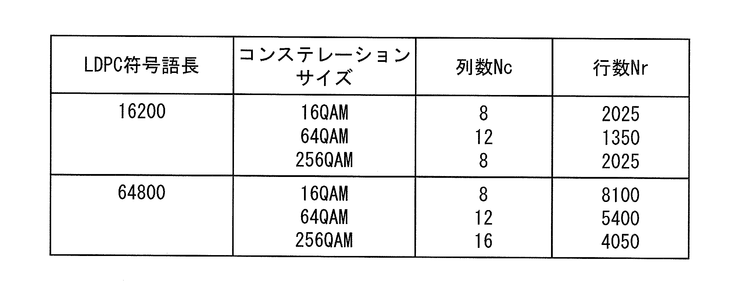
16QAMの場合、4050セル
64QAMの場合、2700セル
256QAMの場合、2025セル
上記の表1によると、QPSKより大きなコンステレーションについては、並列ストリームの数はカラム‐ロウインターリーバの列数に等しい。16K LDPC符号について、16QAMコンステレーション、64QAMコンステレーション、256QAMコンステレーションに対応するビット‐セルデマルチプレクサを、それぞれ、図11、図12、図13に示す。なお、ビットの表記はDVB-T2規格で用いられているものである。 For QPSK: 8100 cells 16QAM: 4050 cells 64QAM: 2700 cells 256QAM: 2025 cells According to Table 1 above, for constellations larger than QPSK, the number of parallel streams is column-row interleaver Equal to the number of columns. For 16K LDPC codes, bit-cell demultiplexers corresponding to 16 QAM constellation, 64 QAM constellation, and 256 QAM constellation are shown in FIG. 11, FIG. 12, and FIG. 13, respectively. The bit notation is used in the DVB-T2 standard.
発明者は、鋭意研究を行った結果、以下の2つの条件が満たされるとき、非常に効率的なインターリーバが提供できるという知見を得た。 «Findings obtained by the inventor»
As a result of intensive studies, the inventor has found that a highly efficient interleaver can be provided when the following two conditions are satisfied.
各コンステレーション語のM個のビットが、LDPC符号語のM個の異なる巡回ブロックにマッピングされる。これは、LDPC符号語のM個の異なる巡回ブロックから1ビットずつコンステレーション語にマッピングする、ことと等価である。この概要を図18(a)に示す。 (Condition 1)
The M bits of each constellation word are mapped to M different cyclic blocks of an LDPC codeword. This is equivalent to mapping to constellation words bit by bit from M different cyclic blocks of an LDPC codeword. An outline of this is shown in FIG.
M個の巡回ブロックにマッピングされるすべてのコンステレーション語が、当該M個の巡回ブロックのみにマッピングされる。これは、QビットからなるM個の異なる巡回ブロックのM×Q個のビットの全ては、Q個のコンステレーション語にのみマッピングされる、ことと等価である。この概要を図18(b)に示す。 (Condition 2)
All constellation words mapped to M cyclic blocks are mapped to only the M cyclic blocks. This is equivalent to that all of the M × Q bits of the M different cyclic blocks of Q bits are mapped only to Q constellation words. The outline of this is shown in FIG.
以下、上記の条件1、条件2を満たすビットインターリーバ(並列ビットインターリーバ)の詳細について説明する。なお、以下において、実質的に同じ処理内容、および、同じ処理内容を行う構成ユニットには同じ符号を付す。 << Embodiment (Part 1) >>
Hereinafter, the details of the bit interleaver (parallel bit interleaver) which satisfies the
ステージB:巡回ブロック内パーミュテーション
ステージC:カラム‐ロウパーミュテーション
ここで、巡回ブロック(間)パーミュテーションは符号語を構成するN個の巡回ブロックの並び順を換えるパーミュテーションであり、巡回ブロック内パーミュテーションは巡回ブロックを構成するQ個のビットの並び順を換えるパーミュテーションであり、カラム‐ロウパーミュテーションは、セクションを構成するM×Q個のビットの並び順を換えるパーミュテーションである。 Stage A: cyclic block (inter) permutation Stage B: intra-cyclic block permutation Stage C: column-row permutation Here, the cyclic block (inter) permutation is N cycles constituting a codeword Permutation to change the order of blocks, in-block permutation is permutation to change the order of Q bits that make up a cyclic block, and column-row permutation forms sections It is a permutation that changes the order of M × Q bits to be processed.
p(b=0)はビットbが0である確率を示し、p(b=1)はビットbが1である確率を示す。ただし、p(b=0)+p(b=1)=1が成り立つ。 LLR (b) = ln [p (b = 0) / p (b = 1)]
p (b = 0) indicates the probability that bit b is 0, and p (b = 1) indicates the probability that bit b is 1. However, p (b = 0) + p (b = 1) = 1 holds.
上述した条件1、条件2を満たすインターリーバ(並列インターリーバ)では、コンステレーション語のビット数Mが巡回ブロック数Nの約数になることを前提としている。しかしながら、常に、MがNの約数になるとは限らない。例として、DVB-T2規格で使用される16K LDPC符号を挙げることができ、16K LDPC符号の符号語はN=45個の巡回ブロックを有する。MがNの約数にならない場合、Mが偶数であるQAMコンステレーションなどの正方形コンステレーションに対するマッピングは容易ではない。 << Further examination by inventor >>
In the interleaver (parallel interleaver) that satisfies

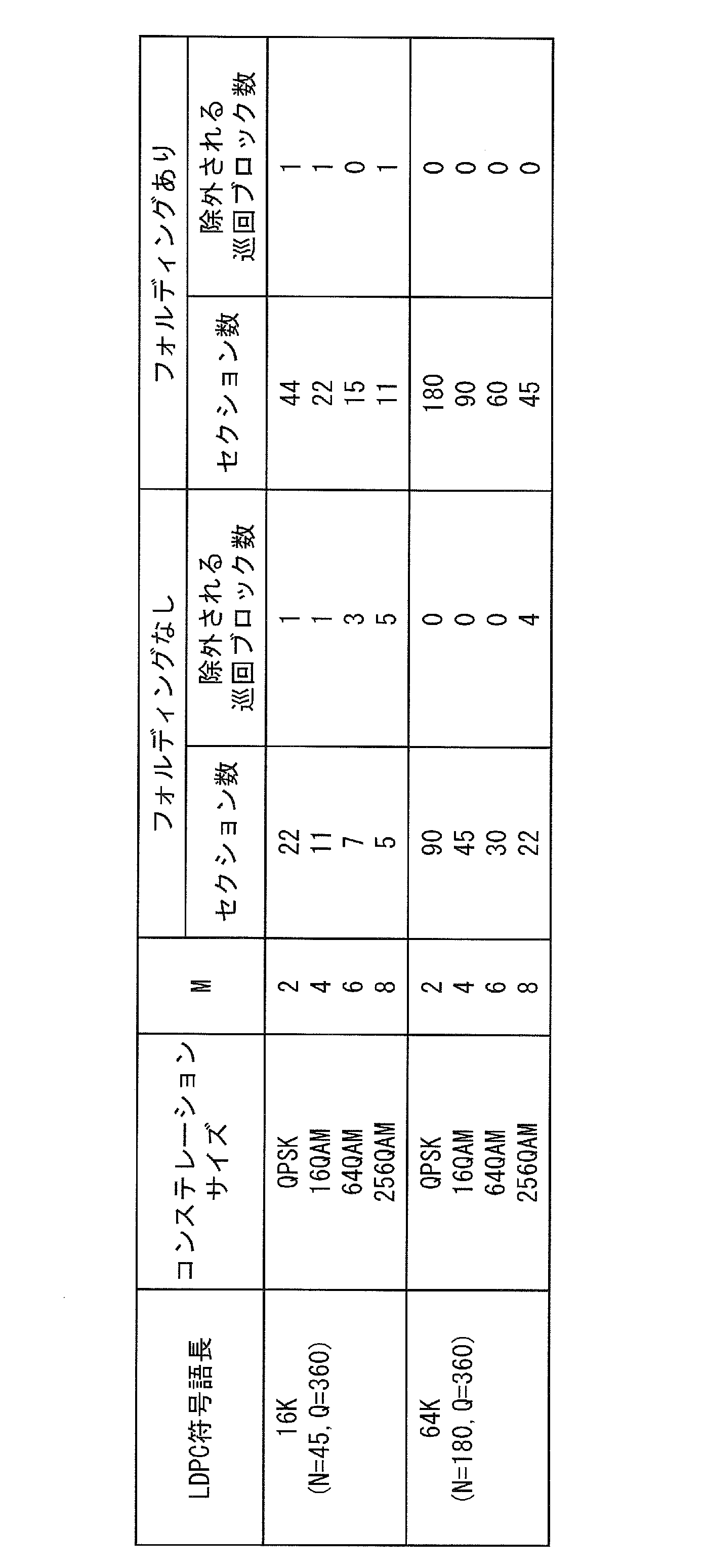
各コンステレーション語のM個のビットが、LDPC符号語のM/F個の異なる巡回ブロックにマッピングされる。これは、LDPC符号語のM/F個の異なる巡回ブロックからF個のビットずつコンステレーション語にマッピングする、ことと等価である。この概要を図31(a)に示す。 (Condition 1A)
The M bits of each constellation word are mapped to M / F different cyclic blocks of the LDPC codeword. This is equivalent to mapping to constellation words of F bits from M / F different cyclic blocks of the LDPC code word. An outline of this is shown in FIG.
M/F個の巡回ブロックにマッピングされるすべてのコンステレーション語が、当該M/F個の巡回ブロックのみにマッピングされる。これは、QビットからなるM/F個の異なる巡回ブロックのM×Q/F個のビットの全ては、Q/F個のコンステレーション語にのみマッピングされる、ことと等価である。この概要を図31(b)に示す。 (Condition 2A)
All constellation words mapped to M / F cyclic blocks are mapped to only the M / F cyclic blocks. This is equivalent to that all of the M × Q / F bits of M / F different cyclic blocks consisting of Q bits are mapped to only Q / F constellation words. An outline of this is shown in FIG.
以下、上記の条件1A、条件2Aを満たすビットインターリーバ(並列ビットインターリーバ)の詳細について説明する。なお、以下において、実質的に同じ処理内容、および、同じ処理内容を行う構成ユニットには同じ符号を付す。 «Embodiment (Part 2)»
The details of the bit interleaver (parallel bit interleaver) satisfying the above conditions 1A and 2A are described below. In the following, the same reference numerals are given to constituent units that perform substantially the same processing content and the same processing content.
以下、NがMの倍数ではなく、フォルディングを行う場合のインターリーバの一例について記載する。 «Embodiment (3)»
Hereinafter, an example of the interleaver in the case where folding is performed instead of N being a multiple of M will be described.
本発明は上記の実施の形態で説明した内容に限定されず、本発明の目的とそれに関連又は付随する目的を達成するためのいかなる形態においても実施可能であり、例えば、以下であってもよい。 «
The present invention is not limited to the contents described in the above embodiment, but can be practiced in any form for achieving the object of the present invention and the objects related to or associated with it, for example, the following may be possible. .
本発明に係るビットインターリーブ方法、ビットインターリーバ、ビットデインターリーブ方法、ビットデインターリーバ、およびデコーダとその効果について説明する。 «
A bit interleaving method, a bit interleaver, a bit deinterleaving method, a bit deinterleaver, and a decoder according to the present invention and their effects will be described.
対応するビットが0であるか1であるかの確率を示すソフトビット列を生成するコンステレーションデマッパと、前記ソフトビット列をビットデインターリーブする第1のビットデインターリーバと、ビットデインターリーブされた前記ソフトビット列をデコードする低密度パリティチェックデコーダと、を備える。 A first decoder, which is an aspect of the present invention, is a decoder for a bit interleaving coded modulation system using a pseudo-cyclic low density parity check code,
A constellation demapper generating a soft bit string indicating the probability that the corresponding bit is 0 or 1, a first bit deinterleaver bit deinterleaving the soft bit string, and the bit de-interleaved And a low density parity check decoder for decoding the soft bit sequence.
2010A ビットパーミュテーションユニット
2021A フォルディングセクションパーミュテーションユニット
2131A、2132A カラム‐ロウパーミュテーションユニット
2500A トランスミッタ
2510 LDPCエンコーダ
2520A ビットインターリーバ
2530 コンステレーションマッパ
2700A、2800A レシーバ
2710 コンステレーションデマッパ
2720A ビットデインターリーバ
2730 LDPCデコーダ
2740 減算ユニット
2750A ビットインターリーバ
Claims (17)
- 疑似巡回低密度パリティチェック符号を用いる通信システムにおけるビットインターリーブ方法であって、
前記ビットインターリーブ方法は、
それぞれがQ個のビットからなるN個の巡回ブロックで構成される前記疑似巡回低密度パリティチェック符号の符号語を受信する受信ステップと、
前記符号語のビットに対して当該符号語のビットの並び順を換えるビットパーミュテーション処理を施すビットパーミュテーションステップと、
前記ビットパーミュテーション処理が施された符号語を、それぞれがM個のビットよりなり、それぞれが所定のコンステレーションの2M個のコンステレーションポイントのいずれか1つを示す複数のコンステレーション語に分割する分割ステップと、
を有し、
前記ビットパーミュテーション処理が施される前の前記符号語はF×N/M個のフォルディングセクションに分割され、Fは1より大きい整数であり、各前記フォルディングセクションはM/F個の前記巡回ブロックからなり、各前記コンステレーション語はF×N/M個の前記フォルディングセクションのうちのいずれか1つと関連付けられており、
前記ビットパーミュテーションステップは、各前記コンステレーション語が、関連付けられている前記フォルディングセクション中のM/F個の異なる前記巡回ブロックのそれぞれのF個のビットからなる計M個のビットから構成され、各前記フォルディングセクションのすべてのビットが当該フォルディングセクションに関連付けられているQ/F個の前記コンステレーション語にのみにマッピングされるように、前記ビットパーミュテーション処理を行う
ことを特徴とするビットインターリーブ方法。 A bit interleaving method in a communication system using a pseudo cyclic low density parity check code, comprising:
The bit interleaving method is
Receiving the codewords of the pseudo-cyclic low density parity check code consisting of N cyclic blocks each consisting of Q bits;
A bit permutation step of performing bit permutation processing for changing the order of bits of the codeword with respect to bits of the codeword;
The codewords subjected to the bit permutation process are formed into a plurality of constellation words, each of which consists of M bits, each of which indicates any one of 2 M constellation points of a predetermined constellation. A dividing step to divide
Have
The codeword before being subjected to the bit permutation process is divided into F × N / M folding sections, F is an integer greater than 1, and each of the folding sections has M / F The cyclic blocks, each constellation word being associated with any one of F × N / M folding sections,
The bit permutation step is configured such that each of the constellation words comprises a total of M bits consisting of F bits of M / F different cyclic blocks in the associated folding section. And performing the bit permutation process such that all bits of each folding section are mapped only to Q / F constellation words associated with the folding section. Bit interleaving method. - 前記ビットパーミュテーションステップは、
F×N/M個の前記フォルディングセクションを互いに独立に、各前記フォルディングセクションのビットに対して当該フォルディングセクションのビットの並び順を換えるフォルディングセクションパーミュテーション処理を施すフォルディングセクションパーミュテーションステップ
を有することを特徴とする請求項1に記載のビットインターリーブ方法。 The bit permutation step is
A folding section permuting process is performed in which F × N / M folding sections are arranged independently of each other to change the order of bits of the folding section with respect to the bits of each folding section. The bit interleaving method according to claim 1, further comprising a mutation step. - 前記フォルディングセクションパーミュテーションステップは、
前記巡回ブロックのQ個のビットが、当該巡回ブロックに対応する前記フォルディングセクションに関連付けられているQ/F個の前記コンステレーション語の同一のロバストレベルを有するビットにマッピングされるように、前記フォルディングセクションパーミュテーション処理を行う
ことを特徴とする請求項2に記載のビットインターリーブ方法。 The folding section permutation step is
The Q bits of the cyclic block are mapped to bits with the same robust level of the Q / F constellation words associated with the folding section corresponding to the cyclic block. The bit interleaving method according to claim 2, wherein folding section permutation processing is performed. - Fは、前記コンステレーションの同一のロバストレベルを有するビットの数と等しい
ことを特徴とする請求項1に記載のビットインターリーブ方法。 The method of bit interleaving according to claim 1, characterized in that F is equal to the number of bits having the same robust level of the constellation. - F=2であり、前記コンステレーションはQAMコンステレーションである
ことを特徴とする請求項1に記載のビットインターリーブ方法。 The method of bit interleaving according to claim 1, characterized in that F = 2 and the constellation is a QAM constellation. - 前記フォルディングセクションパーミュテーションステップは、
前記セクションのM/F×Q個のビットに対して当該M/F×Q個のビットの並び順を換えるカラム-ロウパーミュテーション処理を施すカラム-ロウパーミュテーションステップを有する
ことを特徴とする請求項2に記載のビットインターリーブ方法。 The folding section permutation step is
It has a column-row permutation step of performing column-row permutation processing for changing the arrangement order of the M / F × Q bits to the M / F × Q bits of the section. The bit interleaving method according to claim 2. - 前記カラム-ロウパーミュテーション処理は、M/F×Q個のビットをQ列M/F行の行列の行方向に書き込み、列方向にM×Q/F個のビットを読み出すことと等価な処理である
ことを特徴とする請求項6に記載のビットインターリーブ方法。 The column-row permutation process is equivalent to writing M / F × Q bits in the row direction of a matrix of Q columns and M / F rows and reading M × Q / F bits in the column direction. It is a process. The bit interleaving method of Claim 6 characterized by the above-mentioned. - 疑似巡回低密度パリティチェック符号を用いる通信システムにおいてビットストリームをビットデインターリーブするビットデインターリーブ方法であって、
N×Q個のビットからなるビット列を受信する受信ステップと、
前記疑似巡回低密度パリティチェック符号の符号語を復元するために、受信した前記ビット列のビットに対して当該ビット列のビットの並び順を換える逆ビットパーミュテーション処理を施す逆ビットパーミュテーションステップと、
を有し、
前記逆ビットパーミュテーション処理は、請求項1に記載のビットインターリーブ方法における前記ビットパーミュテーション処理で換えられた並び順を元に戻す処理である
ことを特徴とするビットデインターリーブ方法。 A bit de-interleaving method for bit de-interleaving bit streams in a communication system using a pseudo-cyclic low density parity check code, comprising:
A step of receiving a bit string consisting of N × Q bits;
Reverse bit permutation step of performing reverse bit permutation processing for changing the order of bits of the received bit string to the received bit string to restore a codeword of the pseudo cyclic low density parity check code; ,
Have
The bit deinterleaving method according to claim 1, wherein the reverse bit permutation processing is processing for restoring the order of arrangement changed in the bit permutation processing in the bit interleaving method according to claim 1. - 疑似巡回低密度パリティチェック符号を用いる通信システムにおけるビットインターリーバであって、
前記ビットインターリーバは、
それぞれがQ個のビットからなるN個の巡回ブロックで構成される前記疑似巡回低密度パリティチェック符号の符号語を受信し、前記符号語のビットに対して当該符号語のビットの並び順を換えるビットパーミュテーション処理を施し、前記ビットパーミュテーション処理が施された符号語を、それぞれがM個のビットよりなり、それぞれが所定のコンステレーションの2M個のコンステレーションポイントのいずれか1つを示す複数のコンステレーション語に分割されるように出力するビットパーミュテーション部
を備え、
前記ビットパーミュテーション処理が施される前の前記符号語はF×N/M個のフォルディングセクションに分割され、Fは1より大きい整数であり、各前記フォルディングセクションはM/F個の前記巡回ブロックからなり、各前記コンステレーション語はF×N/M個の前記フォルディングセクションのうちのいずれか1つと関連付けられており、
前記ビットパーミュテーション部は、各前記コンステレーション語が、関連付けられている前記フォルディングセクション中のM/F個の異なる前記巡回ブロックのそれぞれのF個のビットからなる計M個のビットから構成され、各前記フォルディングセクションのすべてのビットが当該フォルディングセクションに関連付けられているQ/F個の前記コンステレーション語にのみにマッピングされるように、前記ビットパーミュテーション処理を行う
ことを特徴とするビットインターリーバ。 A bit interleaver in a communication system using a pseudo-cyclic low density parity check code,
The bit interleaver is
Receiving a codeword of the pseudo-cyclic low-density parity check code consisting of N cyclic blocks each consisting of Q bits, and changing the order of bits of the codeword with respect to the bits of the codeword Each of the codewords subjected to bit permutation processing and subjected to the bit permutation processing is one of 2 M constellation points of a predetermined constellation, each of which consists of M bits. And a bit permutation unit for outputting so as to be divided into a plurality of constellation words indicating
The codeword before being subjected to the bit permutation process is divided into F × N / M folding sections, F is an integer greater than 1, and each of the folding sections has M / F The cyclic blocks, each constellation word being associated with any one of F × N / M folding sections,
The bit permutation unit is configured such that each of the constellation words comprises a total of M bits consisting of F bits of M / F different cyclic blocks in the folding section to which the constellation word is associated. And performing the bit permutation process such that all bits of each folding section are mapped only to Q / F constellation words associated with the folding section. To bit interleaver. - 前記ビットパーミュテーション部は、
F×N/M個の前記フォルディングセクションを互いに独立に、各前記フォルディングセクションのビットに対して当該フォルディングセクションのビットの並び順を換えるフォルディングセクションパーミュテーション処理を施すフォルディングセクションパーミュテーション部
を有することを特徴とする請求項9に記載のビットインターリーバ。 The bit permutation unit
A folding section permuting process is performed in which F × N / M folding sections are arranged independently of each other to change the order of bits of the folding section with respect to the bits of each folding section. The bit interleaver according to claim 9, comprising a mutation unit. - 前記フォルディングセクションパーミュテーション部は、
前記巡回ブロックのQ個のビットが、当該巡回ブロックに対応する前記フォルディングセクションに関連付けられているQ/F個の前記コンステレーション語の同一のロバストレベルを有するビットにマッピングされるように、前記フォルディングセクションパーミュテーション処理を行う
ことを特徴とする請求項10に記載のビットインターリーバ。 The folding section permutation unit
The Q bits of the cyclic block are mapped to bits with the same robust level of the Q / F constellation words associated with the folding section corresponding to the cyclic block. The bit interleaver according to claim 10, characterized in that folding section permutation processing is performed. - Fは、前記コンステレーションの同一のロバストレベルを有するビットの数と等しい
ことを特徴とする請求項9に記載のビットインターリーバ。 The bit interleaver according to claim 9, characterized in that F is equal to the number of bits with the same robust level of the constellation. - F=2であり、前記コンステレーションはQAMコンステレーションである
ことを特徴とする請求項9に記載のビットインターリーバ。 10. The bit interleaver of claim 9, wherein F = 2 and the constellation is a QAM constellation. - 前記フォルディングセクションパーミュテーション部は、
前記セクションのM/F×Q個のビットに対して当該M/F×Q個のビットの並び順を換えるカラム-ロウパーミュテーション処理を施す
ことを特徴とする請求項10に記載のビットインターリーバ。 The folding section permutation unit
A bit-interleave process according to claim 10, characterized in that column-row permutation processing is performed on the M / F x Q bits of the section to change the order of the M / F x Q bits. Lever. - 疑似巡回低密度パリティチェック符号を用いる通信システムにおいてビットストリームをビットデインターリーブするビットデインターリーバであって、
N×Q個のビットからなるビット列を受信し、前記疑似巡回低密度パリティチェック符号の符号語を復元するために、受信した前記ビット列のビットに対して当該ビット列のビットの並び順を換える逆ビットパーミュテーション処理を施す逆ビットパーミュテーション部を備え、
前記逆ビットパーミュテーション処理は、請求項9に記載のビットインターリーバによって実施される前記ビットパーミュテーション処理で換えられた並び順を元に戻す処理である
ことを特徴とするビットデインターリーバ。 A bit deinterleaver for bit deinterleaving bit streams in a communication system using a pseudo-cyclic low density parity check code, comprising:
A reverse bit that changes the order of bits of the received bit string with respect to the bits of the received bit string in order to receive a bit string consisting of N × Q bits and restore the codeword of the pseudo cyclic low density parity check code Has a reverse bit permutation unit that performs permutation processing,
The bit deinterleaver characterized in that the reverse bit permutation process is a process of restoring the arrangement order changed in the bit permutation process performed by the bit interleaver according to claim 9. . - 疑似巡回低密度パリティチェック符号を用いるビットインターリーブ符号化変調システム用のデコーダであって、
対応するビットが0であるか1であるかの確率を示すソフトビット列を生成するコンステレーションデマッパと、
前記ソフトビット列をビットデインターリーブする請求項15に記載のビットデインターリーバと、
ビットデインターリーブされた前記ソフトビット列をデコードする低密度パリティチェックデコーダと、
を備えることを特徴とするデコーダ。 A decoder for a bit interleaved coded modulation system using a pseudo-cyclic low density parity check code,
A constellation demapper that generates a soft bit string indicating the probability that the corresponding bit is 0 or 1;
The bit deinterleaver according to claim 15, wherein the soft bit sequence is bit deinterleaved;
A low density parity check decoder for decoding the bit deinterleaved soft bit sequence;
A decoder characterized in that it comprises: - 前記低密度パリティチェックデコーダの出力から前記低密度パリティチェックデコーダの入力を減算する減算部と、
前記減算部の減算結果を前記コンステレーションデマッパにフィードバックする請求項9に記載のビットインターリーバと、
をさらに備えることを特徴とする請求項16に記載のデコーダ。 A subtraction unit that subtracts the input of the low density parity check decoder from the output of the low density parity check decoder;
10. The bit interleaver according to claim 9, wherein the subtraction result of the subtraction unit is fed back to the constellation demapper.
The decoder of claim 16, further comprising:
Priority Applications (34)
| Application Number | Priority Date | Filing Date | Title |
|---|---|---|---|
| KR1020177033781A KR101849172B1 (en) | 2011-05-18 | 2012-05-18 | Bit interleaver |
| EP15172085.1A EP2940878B1 (en) | 2011-05-18 | 2012-05-18 | Bit interleaver for a bicm system with qc ldpc codes |
| AU2012257207A AU2012257207B2 (en) | 2011-05-18 | 2012-05-18 | Parallel bit interleaver |
| SG2013081039A SG194738A1 (en) | 2011-05-18 | 2012-05-18 | Parallel bit interleaver |
| EA201391503A EA201391503A1 (en) | 2011-05-18 | 2012-05-18 | MODULE OF PARALLEL BITS INTERCONNECTION |
| KR1020217008550A KR102268718B1 (en) | 2011-05-18 | 2012-05-18 | Bit interleave method, bit interleaver, signal processing method and signal processing device |
| KR1020207003682A KR102136204B1 (en) | 2011-05-18 | 2012-05-18 | Bit interleave method, bit interleaver, signal processing method and signal processing device |
| EP12785798.5A EP2566055B1 (en) | 2011-05-18 | 2012-05-18 | Bit interleaver for a BICM system with QC LDPC codes |
| PL12785798T PL2566055T3 (en) | 2011-05-18 | 2012-05-18 | Bit interleaver for a BICM system with QC LDPC codes |
| ES12785798.5T ES2550494T3 (en) | 2011-05-18 | 2012-05-18 | Bit interleaver for a BICM system with QC LDPC codes |
| KR1020147036715A KR101803280B1 (en) | 2011-05-18 | 2012-05-18 | Parallel bit interleaver |
| JP2013515007A JP5719928B2 (en) | 2011-05-18 | 2012-05-18 | Parallel bit interleaver |
| KR1020187009945A KR101871291B1 (en) | 2011-05-18 | 2012-05-18 | Bit interleaver |
| KR1020187017349A KR101942891B1 (en) | 2011-05-18 | 2012-05-18 | Bit interleaver |
| KR1020137028838A KR101507337B1 (en) | 2011-05-18 | 2012-05-18 | Parallel bit interleaver |
| KR1020207020441A KR102196204B1 (en) | 2011-05-18 | 2012-05-18 | Bit interleave method, bit interleaver, signal processing method and signal processing device |
| MX2013012639A MX2013012639A (en) | 2011-05-18 | 2012-05-18 | Parallel bit interleaver. |
| BR112013029037-4A BR112013029037B1 (en) | 2011-05-18 | 2012-05-18 | BIT INTERCALATION METHOD, BIT DECREASER METHOD, BIT INTERCATER, BIT DECREASER AND DECODER |
| CN201280022660.9A CN103636130B (en) | 2011-05-18 | 2012-05-18 | Parallel bit interleaver |
| CA2833459A CA2833459C (en) | 2011-05-18 | 2012-05-18 | Parallel bit interleaver |
| EP18185466.2A EP3416294B1 (en) | 2011-05-18 | 2012-05-18 | Bit interleaver for a bicm system with qc ldpc codes |
| KR1020197001937A KR102030497B1 (en) | 2011-05-18 | 2012-05-18 | Bit interleaver |
| KR1020207036912A KR102233156B1 (en) | 2011-05-18 | 2012-05-18 | Bit interleave method, bit interleaver, signal processing method and signal processing device |
| KR1020197028977A KR102077116B1 (en) | 2011-05-18 | 2012-05-18 | Transmission method and transmission device |
| US14/115,738 US20150128012A1 (en) | 2011-05-18 | 2012-05-18 | Parallel bit interleaver |
| ZA2013/08155A ZA201308155B (en) | 2011-05-18 | 2013-10-31 | Parallel bit interleaver |
| US14/825,389 US9385755B2 (en) | 2011-05-18 | 2015-08-13 | Parallel bit interleaver |
| US15/176,351 US10355715B2 (en) | 2011-05-18 | 2016-06-08 | Parallel bit interleaver |
| AU2016250400A AU2016250400B2 (en) | 2011-05-18 | 2016-10-27 | Parallel Bit Interleaver |
| AU2018201594A AU2018201594B2 (en) | 2011-05-18 | 2018-03-06 | Parallel Bit Interleaver |
| US16/424,775 US11070236B2 (en) | 2011-05-18 | 2019-05-29 | Parallel bit interleaver |
| AU2019253907A AU2019253907B2 (en) | 2011-05-18 | 2019-10-25 | Parallel bit interleaver |
| US17/341,934 US11496157B2 (en) | 2011-05-18 | 2021-06-08 | Parallel bit interleaver |
| US17/959,570 US11894861B2 (en) | 2011-05-18 | 2022-10-04 | Parallel bit interleaver |
Applications Claiming Priority (2)
| Application Number | Priority Date | Filing Date | Title |
|---|---|---|---|
| EP11004124.1 | 2011-05-18 | ||
| EP20110004124 EP2525495A1 (en) | 2011-05-18 | 2011-05-18 | Bit-interleaved coding and modulation (BICM) with quasi-cyclic LDPC codes |
Related Child Applications (2)
| Application Number | Title | Priority Date | Filing Date |
|---|---|---|---|
| US14/115,738 A-371-Of-International US20150128012A1 (en) | 2011-05-18 | 2012-05-18 | Parallel bit interleaver |
| US14/825,389 Continuation US9385755B2 (en) | 2011-05-18 | 2015-08-13 | Parallel bit interleaver |
Publications (1)
| Publication Number | Publication Date |
|---|---|
| WO2012157283A1 true WO2012157283A1 (en) | 2012-11-22 |
Family
ID=44789669
Family Applications (1)
| Application Number | Title | Priority Date | Filing Date |
|---|---|---|---|
| PCT/JP2012/003263 WO2012157283A1 (en) | 2011-05-18 | 2012-05-18 | Parallel bit interleaver |
Country Status (18)
| Country | Link |
|---|---|
| US (6) | US20150128012A1 (en) |
| EP (4) | EP2525495A1 (en) |
| JP (8) | JP5719928B2 (en) |
| KR (11) | KR101849172B1 (en) |
| CN (4) | CN107104678B (en) |
| AU (4) | AU2012257207B2 (en) |
| BR (1) | BR112013029037B1 (en) |
| CA (2) | CA2833459C (en) |
| EA (6) | EA033180B1 (en) |
| ES (2) | ES2702385T3 (en) |
| HU (1) | HUE026185T2 (en) |
| MX (1) | MX2013012639A (en) |
| MY (1) | MY164561A (en) |
| PL (1) | PL2566055T3 (en) |
| SG (2) | SG194738A1 (en) |
| TW (2) | TWI524680B (en) |
| WO (1) | WO2012157283A1 (en) |
| ZA (3) | ZA201308155B (en) |
Cited By (1)
| Publication number | Priority date | Publication date | Assignee | Title |
|---|---|---|---|---|
| CN109560892A (en) * | 2013-12-27 | 2019-04-02 | 松下电器(美国)知识产权公司 | Sending method, method of reseptance and sending device, reception device |
Families Citing this family (41)
| Publication number | Priority date | Publication date | Assignee | Title |
|---|---|---|---|---|
| EP2525498A1 (en) * | 2011-05-18 | 2012-11-21 | Panasonic Corporation | Bit-interleaved coding and modulation (BICM) with quasi-cyclic LDPC codes |
| EP2525497A1 (en) * | 2011-05-18 | 2012-11-21 | Panasonic Corporation | Bit-interleaved coding and modulation (BICM) with quasi-cyclic LDPC codes |
| EP2525496A1 (en) * | 2011-05-18 | 2012-11-21 | Panasonic Corporation | Bit-interleaved coding and modulation (BICM) with quasi-cyclic LDPC codes |
| EP2525495A1 (en) | 2011-05-18 | 2012-11-21 | Panasonic Corporation | Bit-interleaved coding and modulation (BICM) with quasi-cyclic LDPC codes |
| US9577678B2 (en) | 2014-01-29 | 2017-02-21 | Electronics And Telecommunications Research Institute | Bit interleaver for low-density parity check codeword having length of 64800 and code rate of 7/15 and quadrature phase shift keying, and bit interleaving method using same |
| CA2881540C (en) | 2014-02-13 | 2017-08-01 | Electronics And Telecommunications Research Institute | Modulator and modulation method using non-uniform 16-symbol signal constellation for low-density parity check codeword having 4/15 code rate |
| US9543982B2 (en) | 2014-02-13 | 2017-01-10 | Electronics And Telecommunications Research Institute | Modulator and modulation method using non-uniform 16-symbol signal constellation for low-density parity check codeword having 2/15 code rate |
| US10425110B2 (en) | 2014-02-19 | 2019-09-24 | Samsung Electronics Co., Ltd. | Transmitting apparatus and interleaving method thereof |
| KR101800409B1 (en) * | 2014-02-19 | 2017-11-23 | 삼성전자주식회사 | Transmitting apparatus and interleaving method thereof |
| US9602135B2 (en) | 2014-02-20 | 2017-03-21 | Electronics And Telecommunications Research Institute | Bit interleaver for low-density parity check codeword having length of 64800 and code rate of 5/15 and 64-symbol mapping, and bit interleaving method using same |
| CN110784287B (en) * | 2014-02-20 | 2022-04-05 | 上海数字电视国家工程研究中心有限公司 | Interleaving mapping method and de-interleaving de-mapping method of LDPC code words |
| US9602136B2 (en) | 2014-03-06 | 2017-03-21 | Electronics And Telecommunications Research Institute | Bit interleaver for low-density parity check codeword having length of 64800 and code rate of 4/15 and 256-symbol mapping, and bit interleaving method using same |
| EP4340267A3 (en) * | 2014-04-30 | 2024-04-10 | Huawei Technologies Co., Ltd. | Data sending method and apparatus |
| MX2018009641A (en) * | 2014-05-22 | 2021-10-26 | Panasonic Corp | Communication method and communication device. |
| KR102260767B1 (en) | 2014-05-22 | 2021-06-07 | 한국전자통신연구원 | Bit interleaver for 64-symbol mapping and low density parity check codeword with 16200 length, 3/15 rate, and method using the same |
| CA2892171C (en) | 2014-05-22 | 2018-02-13 | Electronics And Telecommunications Research Institute | Bit interleaver for low-density parity check codeword having length of 16200 and code rate of 10/15 and 256-symbol mapping, and bit interleaving method using same |
| US10361720B2 (en) | 2014-05-22 | 2019-07-23 | Electronics And Telecommunications Research Institute | Bit interleaver for low-density parity check codeword having length of 16200 and code rate of 3/15 and 64-symbol mapping, and bit interleaving method using same |
| US10326471B2 (en) | 2014-05-22 | 2019-06-18 | Electronics And Telecommunications Research Institute | Bit interleaver for low-density parity check codeword having length of 16200 and code rate of 3/15 and quadrature phase shift keying, and bit interleaving method using same |
| KR102260775B1 (en) | 2014-05-22 | 2021-06-07 | 한국전자통신연구원 | Bit interleaver for 256-symbol mapping and low density parity check codeword with 16200 length, 10/15 rate, and method using the same |
| EP2947836A1 (en) * | 2014-05-22 | 2015-11-25 | Panasonic Corporation | Cyclic-block permutations for 1D-4096-QAM with quasi-cyclic LDPC codes and code rates 6/15, 7/15, and 8/15 |
| US9600367B2 (en) | 2014-05-22 | 2017-03-21 | Electronics And Telecommunications Research Institute | Bit interleaver for low-density parity check codeword having length of 16200 and code rate of 4/15 and 16-symbol mapping, and bit interleaving method using same |
| US9369151B2 (en) * | 2014-09-25 | 2016-06-14 | Ali Misfer ALKATHAMI | Apparatus and method for resource allocation |
| CN104333435B (en) * | 2014-09-30 | 2017-11-07 | 扬智科技股份有限公司 | Iterative demapping code translator |
| KR102240748B1 (en) | 2015-01-20 | 2021-04-16 | 한국전자통신연구원 | Bit interleaver for qpsk and low density parity check codeword with 64800 length, 3/15 rate, and method using the same |
| KR102240745B1 (en) | 2015-01-20 | 2021-04-16 | 한국전자통신연구원 | Bit interleaver for qpsk and low density parity check codeword with 64800 length, 4/15 rate, and method using the same |
| KR102240750B1 (en) | 2015-01-20 | 2021-04-16 | 한국전자통신연구원 | Bit interleaver for qpsk and low density parity check codeword with 64800 length, 2/15 rate, and method using the same |
| KR102240740B1 (en) | 2015-01-27 | 2021-04-16 | 한국전자통신연구원 | Bit interleaver for 256-symbol mapping and low density parity check codeword with 16200 length, 2/15 rate, and method using the same |
| KR102240744B1 (en) | 2015-01-27 | 2021-04-16 | 한국전자통신연구원 | Bit interleaver for 16-symbol mapping and low density parity check codeword with 16200 length, 2/15 rate, and method using the same |
| KR102240728B1 (en) | 2015-01-27 | 2021-04-16 | 한국전자통신연구원 | Bit interleaver for 64-symbol mapping and low density parity check codeword with 64800 length, 4/15 rate, and method using the same |
| KR102240736B1 (en) | 2015-01-27 | 2021-04-16 | 한국전자통신연구원 | Bit interleaver for 64-symbol mapping and low density parity check codeword with 64800 length, 3/15 rate, and method using the same |
| KR102240741B1 (en) | 2015-01-27 | 2021-04-16 | 한국전자통신연구원 | Bit interleaver for 64-symbol mapping and low density parity check codeword with 16200 length, 2/15 rate, and method using the same |
| DE112016002451T5 (en) * | 2015-06-01 | 2018-03-01 | Sony Corporation | Data processing device and data processing method |
| US10784901B2 (en) | 2015-11-12 | 2020-09-22 | Qualcomm Incorporated | Puncturing for structured low density parity check (LDPC) codes |
| US11043966B2 (en) * | 2016-05-11 | 2021-06-22 | Qualcomm Incorporated | Methods and apparatus for efficiently generating multiple lifted low-density parity-check (LDPC) codes |
| US10291354B2 (en) | 2016-06-14 | 2019-05-14 | Qualcomm Incorporated | High performance, flexible, and compact low-density parity-check (LDPC) code |
| US10979084B2 (en) | 2017-01-06 | 2021-04-13 | Nokia Technologies Oy | Method and apparatus for vector based LDPC base matrix usage and generation |
| WO2018191749A1 (en) | 2017-04-14 | 2018-10-18 | Kandou Labs, S.A. | Pipelined forward error correction for vector signaling code channel |
| US10693587B2 (en) * | 2017-07-10 | 2020-06-23 | Kandou Labs, S.A. | Multi-wire permuted forward error correction |
| TWI757609B (en) * | 2018-08-03 | 2022-03-11 | 日商索尼股份有限公司 | Transmission apparatus and method, receiving apparatus and method for use in communication |
| DE102019200256B4 (en) * | 2019-01-10 | 2020-07-30 | Fraunhofer-Gesellschaft zur Förderung der angewandten Forschung e.V. | Nesters |
| US11196598B1 (en) * | 2020-06-02 | 2021-12-07 | Huawei Technologies Canada Co., Ltd. | Modulation scheme for high order constellation |
Citations (2)
| Publication number | Priority date | Publication date | Assignee | Title |
|---|---|---|---|---|
| JP2008125085A (en) * | 2007-11-13 | 2008-05-29 | Matsushita Electric Ind Co Ltd | Modulator and modulation method |
| WO2009116204A1 (en) * | 2008-03-18 | 2009-09-24 | ソニー株式会社 | Data processing device and data processing method |
Family Cites Families (44)
| Publication number | Priority date | Publication date | Assignee | Title |
|---|---|---|---|---|
| US7090672B2 (en) | 1995-06-07 | 2006-08-15 | Arthrocare Corporation | Method for treating obstructive sleep disorder includes removing tissue from the base of tongue |
| EP1089439A1 (en) * | 1999-09-28 | 2001-04-04 | TELEFONAKTIEBOLAGET L M ERICSSON (publ) | Interleaver and method for interleaving an input data bit sequence using a coded storing of symbol and additional information |
| US6895547B2 (en) | 2001-07-11 | 2005-05-17 | International Business Machines Corporation | Method and apparatus for low density parity check encoding of data |
| US6954885B2 (en) * | 2001-12-14 | 2005-10-11 | Qualcomm Incorporated | Method and apparatus for coding bits of data in parallel |
| US7352817B2 (en) | 2002-09-27 | 2008-04-01 | Ibiquity Digital Corporation | Method and apparatus for interleaving signal bits in a digital audio broadcasting system |
| US7016690B2 (en) | 2003-02-10 | 2006-03-21 | Flarion Technologies, Inc. | Methods and apparatus for updating mobile node location information |
| US7231557B2 (en) * | 2003-04-02 | 2007-06-12 | Qualcomm Incorporated | Methods and apparatus for interleaving in a block-coherent communication system |
| CN100483952C (en) * | 2003-04-02 | 2009-04-29 | 高通股份有限公司 | Extracting soft information in a block-coherent communication system |
| RU2265960C2 (en) * | 2003-06-16 | 2005-12-10 | Федеральное государственное унитарное предприятие "Калужский научно-исследовательский институт телемеханических устройств" | Method for transferring information with use of adaptive alternation |
| JP4534128B2 (en) * | 2004-03-05 | 2010-09-01 | ソニー株式会社 | Encoding method and apparatus |
| WO2006089569A1 (en) * | 2005-02-28 | 2006-08-31 | Ntt Docomo, Inc. | Method and apparatus for transmitting and receiving bit interleaved coded modulation signal |
| KR20060097503A (en) * | 2005-03-11 | 2006-09-14 | 삼성전자주식회사 | Channel interleaving/de-interleaving apparatus in a communication system using a low density parity check code and control method thereof |
| US7774675B1 (en) * | 2005-12-05 | 2010-08-10 | Marvell International Ltd. | LDPC codes and expansion method |
| JP4602418B2 (en) * | 2006-02-02 | 2010-12-22 | 三菱電機株式会社 | Parity check matrix generation method, encoding method, decoding method, communication apparatus, encoder, and decoder |
| WO2007091327A1 (en) * | 2006-02-09 | 2007-08-16 | Fujitsu Limited | Ldpc check matrix creating method, check matrix creator, and code re-transmission method |
| US7830957B2 (en) | 2006-05-02 | 2010-11-09 | Qualcomm Incorporated | Parallel bit interleaver for a wireless system |
| DE102006026895B3 (en) * | 2006-06-09 | 2007-11-08 | Fraunhofer-Gesellschaft zur Förderung der angewandten Forschung e.V. | Convolution interleaver device for processing code word, has interlacing device changing sequence of interlacing units to receive interlaced code words, where interlacing device does not change sequence of symbols within interlacing units |
| CN101162907B (en) * | 2006-10-10 | 2010-11-03 | 华为技术有限公司 | Method and device for constructing low-density parity code check matrix |
| KR101445340B1 (en) * | 2007-06-01 | 2014-09-29 | 삼성전자주식회사 | OFDM transmitting/receiving device for transmitting/receiving OFDM symbol comprising symbols intereaved variably, and methods thereof |
| CN101399554B (en) * | 2007-09-30 | 2012-03-21 | 华为技术有限公司 | Interleaving method and de-interleaving method based on LDPC code and apparatus therefor |
| EP2056510B1 (en) * | 2007-10-30 | 2013-04-03 | Sony Corporation | Data processing apparatus and method |
| TWI497920B (en) * | 2007-11-26 | 2015-08-21 | Sony Corp | Data processing device and data processing method |
| TWI410055B (en) * | 2007-11-26 | 2013-09-21 | Sony Corp | Data processing device, data processing method and program product for performing data processing method on computer |
| TWI538415B (en) * | 2007-11-26 | 2016-06-11 | Sony Corp | Data processing device and data processing method |
| TWI459724B (en) * | 2007-11-26 | 2014-11-01 | Sony Corp | Data processing device and data processing method |
| JP5120862B2 (en) * | 2008-02-18 | 2013-01-16 | サムスン エレクトロニクス カンパニー リミテッド | Channel coding apparatus and method for communication system using low density parity check code |
| PL2254249T3 (en) | 2008-03-03 | 2015-11-30 | Rai Radiotelevisione Italiana S P A | Bit permutation patterns for LDPC coded modulation and 16QAM constellations |
| ITTO20080472A1 (en) * | 2008-06-16 | 2009-12-17 | Rai Radiotelevisione Italiana Spa | METHOD OF PROCESSING DIGITAL SIGNALS AND TRANSMISSION AND RECEPTION SYSTEM THAT IMPLEMENTS THIS METHOD |
| WO2010024914A1 (en) * | 2008-08-29 | 2010-03-04 | Thomson Licensing | System and method for reusing dvb-s2 ldpc codes in dvb-c2 |
| KR101630442B1 (en) * | 2008-10-03 | 2016-06-24 | 톰슨 라이센싱 | Method and Apparatus for Adapting a Bit Interleaver to LDPC Codes and Modulations under AWGN Channel Conditions Using Binary Erasure Surrogate Channels |
| US8732545B2 (en) | 2008-12-26 | 2014-05-20 | Panasonic Corporation | Encoding method and encoder for generating a low-density parity check convolutional code and decoder for decoding a low-density parity check convolutional code using belief propagation |
| WO2010083038A2 (en) * | 2009-01-14 | 2010-07-22 | Thomson Licensing | Method and apparatus for demultiplexer design for multli-edge type ldpc coded modulation |
| US8588623B2 (en) * | 2009-10-12 | 2013-11-19 | Nec Laboratories America, Inc. | Coded polarization-multiplexed iterative polar modulation |
| US8589755B2 (en) * | 2010-06-16 | 2013-11-19 | Nec Laboratories America, Inc. | Reduced-complexity LDPC decoding |
| US8381065B2 (en) * | 2010-10-01 | 2013-02-19 | Nec Laboratories America, Inc. | Modified progressive edge-growth LDPC codes for ultra-high-speed serial optical transport |
| CN102055485A (en) * | 2010-12-24 | 2011-05-11 | 中国人民解放军理工大学 | Quasi-cyclic low-density parity-check (QC-LDPC) code and correcting and linear coding method thereof |
| JP5630278B2 (en) * | 2010-12-28 | 2014-11-26 | ソニー株式会社 | Data processing apparatus and data processing method |
| EP2525495A1 (en) * | 2011-05-18 | 2012-11-21 | Panasonic Corporation | Bit-interleaved coding and modulation (BICM) with quasi-cyclic LDPC codes |
| EP2525497A1 (en) * | 2011-05-18 | 2012-11-21 | Panasonic Corporation | Bit-interleaved coding and modulation (BICM) with quasi-cyclic LDPC codes |
| EP2525498A1 (en) * | 2011-05-18 | 2012-11-21 | Panasonic Corporation | Bit-interleaved coding and modulation (BICM) with quasi-cyclic LDPC codes |
| EP2525496A1 (en) * | 2011-05-18 | 2012-11-21 | Panasonic Corporation | Bit-interleaved coding and modulation (BICM) with quasi-cyclic LDPC codes |
| EP2552043A1 (en) * | 2011-07-25 | 2013-01-30 | Panasonic Corporation | Spatial multiplexing for bit-interleaved coding and modulation with quasi-cyclic LDPC codes |
| US9654316B2 (en) * | 2012-07-27 | 2017-05-16 | Sun Patent Trust | Transmission method, transmitter, reception method, and receiver |
| CA2949117C (en) | 2013-05-17 | 2021-11-30 | Sw Feesaver, Llc | Water skimming device and method |
-
2011
- 2011-05-18 EP EP20110004124 patent/EP2525495A1/en not_active Withdrawn
-
2012
- 2012-05-18 SG SG2013081039A patent/SG194738A1/en unknown
- 2012-05-18 CN CN201710066082.3A patent/CN107104678B/en active Active
- 2012-05-18 KR KR1020177033781A patent/KR101849172B1/en active IP Right Grant
- 2012-05-18 KR KR1020207003682A patent/KR102136204B1/en active IP Right Grant
- 2012-05-18 KR KR1020207020441A patent/KR102196204B1/en active IP Right Grant
- 2012-05-18 EA EA201891816A patent/EA033180B1/en not_active IP Right Cessation
- 2012-05-18 CA CA2833459A patent/CA2833459C/en active Active
- 2012-05-18 BR BR112013029037-4A patent/BR112013029037B1/en active IP Right Grant
- 2012-05-18 TW TW101117763A patent/TWI524680B/en active
- 2012-05-18 HU HUE12785798A patent/HUE026185T2/en unknown
- 2012-05-18 ES ES15172085T patent/ES2702385T3/en active Active
- 2012-05-18 KR KR1020217008550A patent/KR102268718B1/en active IP Right Grant
- 2012-05-18 EP EP15172085.1A patent/EP2940878B1/en active Active
- 2012-05-18 EA EA202190145A patent/EA039717B1/en unknown
- 2012-05-18 AU AU2012257207A patent/AU2012257207B2/en active Active
- 2012-05-18 EA EA201391503A patent/EA201391503A1/en unknown
- 2012-05-18 CN CN201710066127.7A patent/CN107094024B/en active Active
- 2012-05-18 SG SG10201910330UA patent/SG10201910330UA/en unknown
- 2012-05-18 CN CN201710066088.0A patent/CN107094023B/en active Active
- 2012-05-18 PL PL12785798T patent/PL2566055T3/en unknown
- 2012-05-18 EA EA202090576A patent/EA037756B1/en not_active IP Right Cessation
- 2012-05-18 EA EA201991080A patent/EA035425B1/en not_active IP Right Cessation
- 2012-05-18 CN CN201280022660.9A patent/CN103636130B/en active Active
- 2012-05-18 JP JP2013515007A patent/JP5719928B2/en active Active
- 2012-05-18 EP EP18185466.2A patent/EP3416294B1/en active Active
- 2012-05-18 KR KR1020147036715A patent/KR101803280B1/en active IP Right Grant
- 2012-05-18 TW TW104144047A patent/TWI569586B/en active
- 2012-05-18 KR KR1020187009945A patent/KR101871291B1/en active IP Right Grant
- 2012-05-18 US US14/115,738 patent/US20150128012A1/en not_active Abandoned
- 2012-05-18 MY MYPI2013702017A patent/MY164561A/en unknown
- 2012-05-18 EA EA201691736A patent/EA031465B1/en not_active IP Right Cessation
- 2012-05-18 WO PCT/JP2012/003263 patent/WO2012157283A1/en active Application Filing
- 2012-05-18 KR KR1020197001937A patent/KR102030497B1/en active IP Right Grant
- 2012-05-18 EP EP12785798.5A patent/EP2566055B1/en active Active
- 2012-05-18 KR KR1020187017349A patent/KR101942891B1/en active IP Right Grant
- 2012-05-18 KR KR1020197028977A patent/KR102077116B1/en active IP Right Grant
- 2012-05-18 CA CA3015973A patent/CA3015973C/en active Active
- 2012-05-18 ES ES12785798.5T patent/ES2550494T3/en active Active
- 2012-05-18 KR KR1020137028838A patent/KR101507337B1/en active IP Right Grant
- 2012-05-18 MX MX2013012639A patent/MX2013012639A/en active IP Right Grant
- 2012-05-18 KR KR1020207036912A patent/KR102233156B1/en active IP Right Grant
-
2013
- 2013-10-31 ZA ZA2013/08155A patent/ZA201308155B/en unknown
-
2015
- 2015-03-19 JP JP2015056275A patent/JP5852757B2/en active Active
- 2015-08-13 US US14/825,389 patent/US9385755B2/en active Active
- 2015-12-04 JP JP2015237158A patent/JP6010208B2/en active Active
-
2016
- 2016-06-08 US US15/176,351 patent/US10355715B2/en active Active
- 2016-09-14 JP JP2016179350A patent/JP6208308B2/en active Active
- 2016-10-27 AU AU2016250400A patent/AU2016250400B2/en active Active
-
2017
- 2017-09-04 JP JP2017169317A patent/JP6386641B2/en active Active
- 2017-12-12 ZA ZA2017/08404A patent/ZA201708404B/en unknown
- 2017-12-12 ZA ZA2017/08403A patent/ZA201708403B/en unknown
-
2018
- 2018-03-06 AU AU2018201594A patent/AU2018201594B2/en active Active
- 2018-08-03 JP JP2018146401A patent/JP6559307B2/en active Active
-
2019
- 2019-05-29 US US16/424,775 patent/US11070236B2/en active Active
- 2019-07-16 JP JP2019130812A patent/JP6772346B2/en active Active
- 2019-10-25 AU AU2019253907A patent/AU2019253907B2/en active Active
-
2020
- 2020-09-30 JP JP2020164383A patent/JP7011014B2/en active Active
-
2021
- 2021-06-08 US US17/341,934 patent/US11496157B2/en active Active
-
2022
- 2022-10-04 US US17/959,570 patent/US11894861B2/en active Active
Patent Citations (2)
| Publication number | Priority date | Publication date | Assignee | Title |
|---|---|---|---|---|
| JP2008125085A (en) * | 2007-11-13 | 2008-05-29 | Matsushita Electric Ind Co Ltd | Modulator and modulation method |
| WO2009116204A1 (en) * | 2008-03-18 | 2009-09-24 | ソニー株式会社 | Data processing device and data processing method |
Non-Patent Citations (2)
| Title |
|---|
| DOUILLARD, C.: "The Bit Interleaved Coded Modulation module for DVB-NGH: Enhanced features for mobile reception", TELECOMMUNICATIONS (ICT), 2012 19TH INTERNATIONAL CONFERENCE, 23 April 2012 (2012-04-23) * |
| See also references of EP2566055A4 * |
Cited By (3)
| Publication number | Priority date | Publication date | Assignee | Title |
|---|---|---|---|---|
| CN109560892A (en) * | 2013-12-27 | 2019-04-02 | 松下电器(美国)知识产权公司 | Sending method, method of reseptance and sending device, reception device |
| JP2019165511A (en) * | 2013-12-27 | 2019-09-26 | パナソニック インテレクチュアル プロパティ コーポレーション オブ アメリカPanasonic Intellectual Property Corporation of America | Transmission method, reception method, transmission device, and reception device |
| CN109560892B (en) * | 2013-12-27 | 2021-04-30 | 松下电器(美国)知识产权公司 | Transmission method, reception method, transmission device, and reception device |
Also Published As
Similar Documents
| Publication | Publication Date | Title |
|---|---|---|
| JP7011014B2 (en) | Parallel bit interleaver | |
| JP6568288B2 (en) | Parallel bit interleaver | |
| JP6567154B2 (en) | Parallel bit interleaver | |
| WO2012157282A1 (en) | Parallel bit interleaver |
Legal Events
| Date | Code | Title | Description |
|---|---|---|---|
| WWE | Wipo information: entry into national phase |
Ref document number: 2012785798 Country of ref document: EP |
|
| 121 | Ep: the epo has been informed by wipo that ep was designated in this application |
Ref document number: 12785798 Country of ref document: EP Kind code of ref document: A1 |
|
| ENP | Entry into the national phase |
Ref document number: 2013515007 Country of ref document: JP Kind code of ref document: A |
|
| ENP | Entry into the national phase |
Ref document number: 2833459 Country of ref document: CA |
|
| WWE | Wipo information: entry into national phase |
Ref document number: MX/A/2013/012639 Country of ref document: MX |
|
| ENP | Entry into the national phase |
Ref document number: 20137028838 Country of ref document: KR Kind code of ref document: A |
|
| WWE | Wipo information: entry into national phase |
Ref document number: 14115738 Country of ref document: US |
|
| ENP | Entry into the national phase |
Ref document number: 2012257207 Country of ref document: AU Date of ref document: 20120518 Kind code of ref document: A |
|
| WWE | Wipo information: entry into national phase |
Ref document number: 201391503 Country of ref document: EA |
|
| NENP | Non-entry into the national phase |
Ref country code: DE |
|
| REG | Reference to national code |
Ref country code: BR Ref legal event code: B01A Ref document number: 112013029037 Country of ref document: BR |
|
| WWE | Wipo information: entry into national phase |
Ref document number: IDP00201607959 Country of ref document: ID |
|
| ENP | Entry into the national phase |
Ref document number: 112013029037 Country of ref document: BR Kind code of ref document: A2 Effective date: 20131111 |