WO2012153750A1 - 風力発電装置 - Google Patents
風力発電装置 Download PDFInfo
- Publication number
- WO2012153750A1 WO2012153750A1 PCT/JP2012/061811 JP2012061811W WO2012153750A1 WO 2012153750 A1 WO2012153750 A1 WO 2012153750A1 JP 2012061811 W JP2012061811 W JP 2012061811W WO 2012153750 A1 WO2012153750 A1 WO 2012153750A1
- Authority
- WO
- WIPO (PCT)
- Prior art keywords
- support plate
- generator
- shaft
- gear
- windmill
- Prior art date
- Legal status (The legal status is an assumption and is not a legal conclusion. Google has not performed a legal analysis and makes no representation as to the accuracy of the status listed.)
- Ceased
Links
Images







Classifications
-
- F—MECHANICAL ENGINEERING; LIGHTING; HEATING; WEAPONS; BLASTING
- F03—MACHINES OR ENGINES FOR LIQUIDS; WIND, SPRING, OR WEIGHT MOTORS; PRODUCING MECHANICAL POWER OR A REACTIVE PROPULSIVE THRUST, NOT OTHERWISE PROVIDED FOR
- F03D—WIND MOTORS
- F03D15/00—Transmission of mechanical power
-
- F—MECHANICAL ENGINEERING; LIGHTING; HEATING; WEAPONS; BLASTING
- F03—MACHINES OR ENGINES FOR LIQUIDS; WIND, SPRING, OR WEIGHT MOTORS; PRODUCING MECHANICAL POWER OR A REACTIVE PROPULSIVE THRUST, NOT OTHERWISE PROVIDED FOR
- F03D—WIND MOTORS
- F03D15/00—Transmission of mechanical power
- F03D15/10—Transmission of mechanical power using gearing not limited to rotary motion, e.g. with oscillating or reciprocating members
-
- Y—GENERAL TAGGING OF NEW TECHNOLOGICAL DEVELOPMENTS; GENERAL TAGGING OF CROSS-SECTIONAL TECHNOLOGIES SPANNING OVER SEVERAL SECTIONS OF THE IPC; TECHNICAL SUBJECTS COVERED BY FORMER USPC CROSS-REFERENCE ART COLLECTIONS [XRACs] AND DIGESTS
- Y02—TECHNOLOGIES OR APPLICATIONS FOR MITIGATION OR ADAPTATION AGAINST CLIMATE CHANGE
- Y02E—REDUCTION OF GREENHOUSE GAS [GHG] EMISSIONS, RELATED TO ENERGY GENERATION, TRANSMISSION OR DISTRIBUTION
- Y02E10/00—Energy generation through renewable energy sources
- Y02E10/70—Wind energy
- Y02E10/72—Wind turbines with rotation axis in wind direction
Definitions
- the present invention relates to a wind power generator that generates power using wind power.
- the curved blade wind turbine disclosed in Japanese Utility Model Publication No. 62-000171 is a wind turbine, two bearing support bases, a support, as shown in FIG. 2 after amendment dated March 10, 1986.
- a stand, a generator, a large gear, and a small gear are provided.
- the main shaft of the wind turbine is provided on two bearing support bases.
- the support base is disposed horizontally between the two bearing support bases, and the generator is fixed on the support base.
- the large gear is fixed to the main shaft of the windmill
- the small gear is fixed to the main shaft of the generator.
- the rotation of the main shaft of the wind turbine rotates the main shaft of the generator via the large gear and the small gear to generate power.
- Japanese Utility Model Publication No. 62-000171 Japanese Utility Model Publication No. 62-000171
- the main object of the present invention is to easily exchange the transmission mechanism, and also to accurately mesh the gears of the transmission mechanism.
- a wind turbine generator includes a wind turbine shaft facing in a horizontal direction, and a plurality of blades provided at a front end of the wind turbine shaft and extending radially outward with respect to the wind turbine shaft.
- a windmill portion having a first support plate that supports a front portion of the windmill shaft behind the windmill portion, a second support plate that supports a rear portion of the windmill shaft, Below, a generator fixed to the front main surface of the second support plate, a transmission mechanism for transmitting power from the windmill shaft to the generator, the generator, the second support plate, and A generator shaft parallel to the wind turbine shaft, a rotor magnet that rotates together with the generator shaft, and the rotor magnet.
- a stator core which is a laminated steel plate, and a coil provided on a tooth of the stator core, and the transmission mechanism is mounted on the windmill shaft on the rear side of the second support plate.
- a first gear attached, and a diameter smaller than that of the first gear, attached to the generator shaft penetrating the second support plate on a rear side of the second support plate, and the first gear;
- a second gear that meshes.
- the transmission mechanism can be easily replaced by removing the nacelle.
- the gears of the transmission mechanism can be meshed with high accuracy.
- FIG. 1 is a diagram illustrating a wind turbine generator.
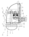
- FIG. 2 is a cross-sectional view of the wind turbine generator.
- FIG. 3 is a side view of the first support plate.
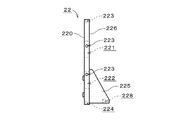
- FIG. 4 is a side view of the second support plate.
- FIG. 5 is a side view of the fixing portion.
- FIG. 6 is a cross-sectional view of the generator.
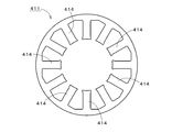
- FIG. 7 is a plan view of the stator core.
- FIG. 8 is a view showing the tip of the tooth.
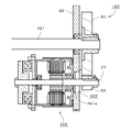
- FIG. 9 is a diagram illustrating a generator and a transmission mechanism.
- FIG. 10 is a rear view of the main body with the nacelle removed.
- FIG. 11 is a front view of the main body with the nacelle removed.
- FIG. 12 is a side view of the main body with the nacelle removed.
- FIG. 1 is a diagram showing a wind turbine generator 10 according to an embodiment of the present invention.
- the wind power generator 10 includes a windmill unit 11, a main body unit 12, a tail unit 13, and a pole 14.
- the windmill portion 11 is fixed to the front side of the main body portion 12, that is, the left side in FIG.
- the tail portion 13 is fixed to the rear side of the main body portion 12, that is, the right side in FIG.
- the main body 12 is supported by a pole 14.
- FIG. 2 is a cross-sectional view of the wind power generator 10.
- the windmill unit 11 includes a plurality of blades 111, a disk-shaped blade fixing unit 112, and a cap unit 113.
- the blade 111 is fixed to the outer edge portion of the blade fixing portion 112.
- the cap portion 113 is attached to the front side of the blade fixing portion 112 and is curved so as to be convex toward the front.
- the main body 12 includes a windmill shaft 121, a generator 122, a transmission mechanism 123, a frame 124, and a streamlined nacelle 125.
- the windmill shaft 121 faces in the horizontal direction. Note that the windmill shaft 121 does not have to be exactly horizontal as long as it is approximately horizontal.
- a blade fixing portion 112 is attached to the front end of the windmill shaft 121.
- the blade 111 extends outward in the radial direction around the central axis J1 with respect to the windmill shaft 121.
- the generator 122 is located below the windmill shaft 121.
- the generator 122 is preferably present in the vicinity of the wind turbine shaft 121. This prevents the presence of the generator 122 from affecting the flow of air passing through the wind turbine unit 11.
- the frame unit 124 includes a first support plate 21, a second support plate 22, and a fixing unit 23.
- the first support plate 21 and the second support plate 22 are arranged along the central axis J1 behind the wind turbine unit 11.
- the first support plate 21 and the second support plate 22 are perpendicular to the central axis J1.
- the length of the first support plate 21 in the vertical direction is longer than that of the second support plate 22.
- the fixing part 23 has a plate shape perpendicular to the vertical direction. The lower part of the first support plate 21 and the lower part of the second support plate 22 are fixed on the upper surface of the fixing part 23.
- FIG. 3 is a side view of the first support plate 21.
- the first support plate 21 includes a first support plate main body 210 and first support ribs 215.
- the first support plate main body 210 is a plate perpendicular to the central axis J1.
- the first support plate main body 210 is provided with a first support hole 211 indicated by a broken line and a plurality of screw holes 213 and 214.
- the first support hole 211 passes through the first support plate main body 210.
- the plurality of screw holes 213 and 214 are provided on the side surface and the lower surface of the first support plate main body 210.
- the first support rib 215 protrudes rearward from the main surface 216 on the rear side of the first support plate main body 210.
- the first support rib 215 is screwed to the first support plate body 210.
- a screw hole 218 is provided on the lower surface of the first support rib 215.
- FIG. 4 is a side view of the second support plate 22.
- the second support plate 22 includes a second support plate main body 220 and second support ribs 225.
- the second support plate main body 220 is a plate perpendicular to the central axis J1.
- the second support plate main body 210 is provided with a second support hole 221, an attachment hole 222, and a plurality of screw holes 223 and 224.
- the second support hole 221 and the attachment hole 222 penetrate the second support plate main body 220.
- the second support hole 221 is located above the attachment hole 222.
- the plurality of screw holes 223 and 224 are provided on the side surface and the lower surface of the second support plate 22.
- the second support rib 225 protrudes rearward from the main surface 226 on the rear side of the second support plate main body 220.
- the second support rib 225 is screwed to the second support plate main body 220.
- a screw hole 228 is provided on the lower surface of the second support rib 225.
- FIG. 5 is a side view of the fixing portion 23.
- the fixing portion 23 includes a front groove portion 231, a rear groove portion 232, a lead wire extraction hole 233, and a plurality of screw holes 234.
- the front groove portion 231 and the rear groove portion 232 extend in a direction perpendicular to the paper surface in FIG.
- a plurality of holes 231 a are provided at the bottom of the front groove 231.
- a plurality of hole portions 232 a are provided at the bottom of the rear groove portion 232.
- the plurality of screw holes 234 are provided on the side surface of the fixing portion 23.
- a hole is also provided at a position facing the first support rib 215 and the second support rib 225.
- a ball bearing 126 is fixed in the first support hole 211 and the second support hole 221.
- the 1st support plate 21 and the 2nd support plate 22 support the front part and rear part of the windmill shaft 121 via the ball bearing 126 so that rotation is possible.
- the generator 122 is screwed in the vicinity of the attachment hole 222 of the main surface 227 on the front side.
- a lead wire 127 is connected to the generator 122.
- the lead wire 127 is connected to the controller (control device) through the inside of the pole 14 from the lead wire extraction hole 233 of the fixing portion 23.
- the generator 122 is separated from the first support rib 215 when viewed from a direction perpendicular to the first support rib 215, that is, a direction perpendicular to the central axis J1 and horizontal. That is, the generator 122 and the first support rib 215 do not overlap in the direction perpendicular to the first support rib 215.
- the transmission mechanism 123 connects the windmill shaft 121 and the generator 122 behind the second support plate 22.
- the front part of the nacelle 125 is closed by the first support plate 21, and the lower part of the nacelle 125 is closed by the fixing part 23.
- the nacelle 125, the first support plate 21, and the fixing portion 23 constitute an accommodation space 9 that accommodates the generator 122, the second support plate 22, and the transmission mechanism 123. Thereby, entry of dust, water, or the like into the main body 12 is suppressed. Since the first support plate 21 and the fixing portion 23 also serve as members constituting the housing space 9 together with the nacelle 125, the number of components of the wind power generator 10 can be reduced.
- the wind turbine unit 11 and the wind turbine shaft 121 are rotated by the air current, and the power from the wind turbine shaft 121 is transmitted to the generator 122 via the transmission mechanism 123. Then, the electric power generated by the generator 122 is transmitted via the lead wire 127.
- FIG. 6 is an enlarged view showing the vicinity of the generator 122 of FIG.
- the generator 122 is an inner rotor type, and includes a rotating unit 3 and a stationary unit 4.
- the rotating unit 3 includes a generator shaft 31, a yoke 32, and a rotor magnet 33.
- the generator shaft 31 passes through the second support plate 22.
- the central axis J2 of the generator shaft 31 is parallel to the central axis J1 of the windmill shaft 121 of FIG.
- the yoke 32 is substantially cylindrical and is fixed to the generator shaft 31.
- the yoke 32 is formed by laminating thin plate-shaped magnetic steel plates.
- the rotor magnet 33 is inserted into a through hole provided in the yoke 32.
- the stationary part 4 includes a stator 41, a cover part 42, and ball bearings 431 and 432.
- the stator 41 has an annular shape centered on the central axis J ⁇ b> 2 of the generator shaft 31 and is attached to the inner peripheral surface of the cover portion 42.
- the stator 41 is opposed to the rotor magnet 33 in the radial direction with the central axis J2 as the center.
- the stator 41 includes a stator core 411, an insulator 412, and a coil 413.
- the stator core 411 is a laminated steel plate in which a plurality of magnetic steel plates are laminated. As shown in FIG. 7, the stator core 411 includes a plurality of teeth 414 extending inward in the radial direction.
- a coil 413 is formed by winding a conductive wire on each tooth 414 via an insulator 412 shown in FIG.
- At least one minute protrusion 414a is provided at the tip of the tooth 414.
- the number of protrusions 414a is three.
- the plurality of protrusions 414a are arranged in the circumferential direction. Thereby, the cogging torque generated between the stator 41 and the rotor magnet 33 can be reduced.
- at least one groove may be provided instead of the protrusion 414a.
- the protrusion 414 a and the groove may be provided on the outer surface of the yoke 32.
- the number of protrusions 414a and grooves is not limited to the above.
- the cover part 42 includes a first cover member 421, a second cover member 422, and an outer cover member 423.
- the first cover member 421 is located on the front side of the second cover member 422.
- the first cover member 421 includes a first lid portion 441 and a first cylindrical portion 442.
- the first lid portion 441 is perpendicular to the central axis J2, and a ball bearing 431 is attached to the central portion.
- the first cylindrical portion 442 extends from the outer edge portion of the first lid portion 441 toward the second cover member 422.
- the second cover member 422 includes a second lid portion 451 and a second cylindrical portion 452.
- the second lid portion 451 is perpendicular to the central axis J2, and a ball bearing 432 is attached to the central portion.
- the second cylindrical portion 452 extends from the outer edge portion of the second lid portion 451 toward the first cover member 421.
- the first cover member 421 and the second cover member 422 rotatably support the generator shaft 31 via ball bearings 431 and 432.
- the outer cover member 423 covers the outer peripheral surface of the first cylindrical portion 442 and the outer peripheral surface of the second cylindrical portion 452.
- the second lid portion 451 is provided with an annular projecting portion 451 a that projects toward the rear of the main body portion 12.
- the rotor magnet 33 rotates together with the generator shaft 31, and electric power is generated in the stator 41.
- the generator 122 can generate electric power with higher efficiency than a coreless generator of the same size.
- the size of the rotor magnet 33 and the stator 41 can be reduced as compared with the coreless type, and the generator 122 can be downsized.
- the generator 122 can be manufactured at low cost.
- the electromagnetic brake 46 is provided on the left side of the first cover member 421 in FIG. 6, that is, on the first support plate 21 side. This forcibly prevents the rotating unit 3 from rotating excessively.
- FIG. 9 is an enlarged view showing the generator 122 and the transmission mechanism 123.
- the transmission mechanism 123 includes a first gear 51 and a second gear 52.
- the first gear 51 and the second gear 52 are spur gears.
- the first gear 51 is made of resin, and the second gear 52 is made of metal.
- the first gear 51 is attached to the rear end portion of the wind turbine shaft 121 on the rear side of the second support plate 22.
- the second gear 52 is attached to the rear end portion of the generator shaft 31 on the rear side of the second support plate 22 and meshes with the first gear 51.
- the outer diameter of the second gear 52 is smaller than that of the first gear 51. Further, the outer diameter of the second gear 52 is smaller than the diameter of the mounting hole 222 of the second support plate 22.
- FIG. 10 is a view of the main body 12 with the nacelle 125 removed as viewed from the rear side.
- the maximum width of the second support plate 22 in the left-right direction of FIG. 10, that is, in the direction vertical and horizontal to the windmill shaft 121 is larger than the width of the first gear 51 in the same direction.
- the upper end of the second support plate 22 is located above the upper end of the first gear 51.
- the rotation of the wind turbine shaft 121 can be increased by the first gear 51 and the second gear 52, and the generator shaft 31 can be rotated at a high speed. Thereby, electric power generation can be performed efficiently.
- FIG. 11 is a front view of the main body 12 with the nacelle removed.
- FIG. 12 is a side view of the main body 12 with the nacelle 125 removed.
- the position of the first support plate 21 in the central axis J1 direction is accurately determined by bringing the inner wall of the front groove 231 and the first support plate main body 210 into contact with each other in the central axis J1 direction.
- the lower portion of the first support rib 215 is in contact with the upper surface of the fixed portion 23. Thereby, the 1st support plate 21 can be stably arrange
- the lower end portion of the second support plate main body 220 is disposed in the rear groove portion 232 of the fixing portion 23, and the screw 128 is inserted into the screw hole 224 and the hole portion 232 a of the rear groove portion 232. Further, the screw 129 is inserted into the screw hole 228 of the second support rib 225 and the hole of the fixing portion 23.
- the position of the second support plate 22 in the central axis J1 direction is accurately determined by bringing the inner wall of the rear groove 232 and the second support plate main body 220 into contact with each other in the central axis J1 direction.
- the lower portion of the second support rib 225 is in contact with the upper surface of the fixing portion 23.
- the 2nd support plate 22 is stably arrange
- the operation of fixing the second support plate 22 to the fixing portion 23 may be performed prior to the operation of fixing the first support plate 21 to the fixing portion 23, or may be performed in parallel.
- the generator shaft 31 with the second gear 52 attached to the rear end is inserted into the attachment hole 222 of the second support plate 22, and the protrusion 451 a is attached to the attachment hole 222.
- a ball bearing 126 is inserted into the first support hole 211 and the second support hole 221, and further, a windmill shaft 121 is inserted as shown in FIG. 12.
- the first gear 51 is attached to the rear end portion of the windmill shaft 121 so as to mesh with the second gear 52.
- the windmill portion 11 and the tail portion 13 are attached to the front end portion of the windmill shaft 121 and the rear end portion of the fixing portion 23, respectively.
- the windmill part 11 and the tail part 13 may be previously attached to the windmill shaft 121 and the fixed part 23, respectively.
- the nacelle 125 shown in FIG. 1 is disposed on the outer edges of the first support plate 21 and the second support plate 22 shown in FIG.
- the screw 130 is inserted into the screw hole 213 on the side surface of the first support plate 21 and the screw hole 223 on the side surface of the second support plate 22 through the nacelle 125.
- the nacelle 125 is fixed to the first support plate 21 and the second support plate 22.
- another screw 130 is inserted into the screw hole 234 of the fixing portion 23 via the nacelle 125, and the lower portion of the nacelle 125 is fixed to the fixing portion 23.
- the pole 14 is fixed to the fixing portion 23, and the assembly of the wind turbine generator 10 is completed.
- the structure of the wind power generator 10 and the flow of assembly were demonstrated, in the wind power generator 10 installed outdoors, maintenance of each component is needed.
- the first gear 51 and the second gear 52 of the transmission mechanism 123 are easily worn, and it is necessary to periodically replace these components.
- the wind turbine generator of the comparative example in which the transmission mechanism exists between the first support plate and the second support plate is compared with the wind turbine generator 10 of FIG.
- a large-scale work for removing at least the nacelle and the second support plate is required.
- the wind power generator 10 of the comparative example in which the generator is provided on the support base fixed to the second support plate.
- the wind turbine generator of the comparative example it is necessary to adjust the postures of the second support plate and the support base so that the generator shaft is horizontal.
- the generator shaft 31 can be easily leveled.
- the wind turbine shaft 121 is supported by the first support plate 21 and the second support plate 22 at the front portion and the rear portion. Thereby, it can be made horizontal easily.
- the distance between the windmill shaft 121 and the generator shaft 31 can be determined easily and accurately.
- the wind turbine shaft 121 and the generator shaft 31 are accurately placed horizontally and at a predetermined interval, whereby the first gear 51 and the second gear 52 can be engaged with each other with high accuracy.
- the fall of the output from the generator 122 can be prevented.
- a thin plate or a film-like member may be interposed between the generator 122 and the second support plate 22. Good.
- the distance between the second gear 52 and the generator 122 can be shortened by fixing the generator 122 to the second support plate 22. Thereby, the load which acts on the ball bearings 431 and 432 in the generator 122 can be reduced. Further, since the position of the generator 122 is also determined by the position of the second support plate 22 in the central axis J1 direction, the position of the center of gravity of the wind power generator 10 can be easily achieved by moving the position of the second support plate 22 at the time of design. Can be changed.
- the generator 122 is disposed close to the windmill shaft 121, whereby the main body 12 can be downsized. Further, the generator 122 is disposed between the first support plate 21 and the second support plate 22, so that the main body portion 12 can be secured while securing the distance between the two ball bearings 126 that support the wind turbine shaft 121. It can be downsized. By downsizing the main body 12, the turbulence of the air current in the vicinity of the main body 12 is suppressed, and a decrease in the rotational speed of the windmill 11 is prevented.
- the wind turbine generator 10 is a so-called speed-up type in which the windmill shaft 121 and the generator shaft 31 are connected via a transmission mechanism 123. Thereby, even if it is a case where the rotation speed of the windmill part 11 is low, the rotation part 3 can be rotated at sufficient rotation speed. In addition, power generation can be performed stably.
- the generator 122 since the rotational speed of the rotating part 3 is sufficiently secured, a high output can be obtained without increasing the size of the stator 41 and the like as compared with a wind power generator that does not have a transmission mechanism.
- the generator 122 is arranged in parallel with the windmill shaft 121. Thereby, the magnitude
- the second support rib 225 has a main surface 226 on the side opposite to the main surface 226 on the rear side, that is, the main surface 227 to which the generator 122 of the second support plate main body 220 is attached. Attached to the surface. Further, when viewed from a direction perpendicular to the first support rib 215, the first support rib 215 and the generator 122 are separated from each other. Therefore, the first support rib 215 and the second support rib 225 are reduced or prevented from interfering with the generator 122 when the generator 122 is removed in a direction perpendicular to the paper surface in FIG.
- the upper end of the second support plate 22 is positioned above the upper end of the first gear 51, and the maximum width of the second support plate 22 in the direction perpendicular to the windmill shaft 121 is horizontal. It is larger than the width in the same direction.
- the diameter of the mounting hole 222 is larger than the outer diameter of the second gear 52.
- the generator 122 may be fixed to the second support plate 22 above the wind turbine shaft 121.
- the first support plate 21 including the first support ribs 215 may be a continuous member.
- the second support rib 225 may be attached to the main surface 227 on the front side of the second support plate 22 as long as it does not interfere with the generator 122.
- the first gear 51 may be made of metal. Positioning with respect to the fixed portion 23 of the first support plate 21 may be performed by providing a protrusion protruding downward at the lower end portion of the first support plate 21 and fitting the protrusion with the hole of the fixed portion 23. The same applies to the second support plate 22.
- the generator 122 excessive rotation of the rotating unit 3 may be prevented by using a brake mechanism other than the electromagnetic brake.
- the brake function may be omitted.
- an outer rotor type in which the rotating part is located outside the stationary part may be used.
- the present invention can be used as a wind power generator that generates power using wind power.
Landscapes
- Engineering & Computer Science (AREA)
- Life Sciences & Earth Sciences (AREA)
- Sustainable Development (AREA)
- Sustainable Energy (AREA)
- Chemical & Material Sciences (AREA)
- Combustion & Propulsion (AREA)
- Mechanical Engineering (AREA)
- General Engineering & Computer Science (AREA)
- Wind Motors (AREA)
Abstract
本発明は、伝達機構の交換を容易に行うことを主たる目的とし、伝達機構のギア同士の噛み合わせを高精度に行うことも目的としている。風力発電装置は、風車シャフトと、複数のブレードを有する風車部と、前記風車シャフトの前方部を支持する第1支持板と、前記風車シャフトの後方部を支持する第2支持板と、前記風車シャフトの上方または下方にて、前記第2支持板に固定され、発電機シャフトを備えた発電機と、前記風車シャフトからの動力を前記発電機に伝達する伝達機構と、前記発電機、前記第2支持板および前記伝達機構を収容するナセルと、を備え、前記伝達機構が、前記第2支持板の後方側にて前記風車シャフトに取り付けられた第1ギアと、前記第1ギアよりも径が小さく、前記第2支持板の後方側にて、前記第2支持板を貫通する前記発電機シャフトに取り付けられ、前記第1ギアと歯合する第2ギアと、を備える。
Description
本発明は、風力を利用して発電を行う風力発電装置に関する。
実開昭62-000171号公報に開示される湾曲羽根風車器は、昭和61年3月10日付けの補正後の第2図に示されるように、風車と、2つの軸受支持台と、支持台と、発電機と、大歯車と、小歯車と、を備える。風車の主軸が、2つの軸受支持台に軸設される。支持台は、2つの軸受支持台の間にて水平に配置され、支持台上に発電機が固定される。2つの軸受支持台の間において、大歯車が風車の主軸に軸固定され、小歯車が発電機の主軸に軸固定される。湾曲羽根風車器では、風車の主軸の回転が、大歯車および小歯車を介して発電機の主軸を回転し、発電が行われる。
実開昭62-000171号公報
ところで、風力発電装置では、風車のシャフトと発電機のシャフトとを接続する伝達機構のギア等の部品が摩耗しやすい。実開昭62-000171号公報では、大歯車および小歯車を交換する際に、湾曲羽根風車器の分解に時間を要し、湾曲羽根風車器のメンテナンスを容易に行うことができない。また、発電機の主軸を水平とするために、発電機が固定される支持台と軸受支持台とを高精度に調整する必要があり、湾曲羽根風車器の組み立てに時間が必要となる。発電機の主軸と風車の主軸とが平行でない場合、大歯車と小歯車との間に大きな負荷が加わる。その結果、歯車のきしみが発生したり、歯車が破損してしまう虞がある。
本発明は、伝達機構の交換を容易に行うことを主たる目的とし、伝達機構のギア同士の噛み合わせを高精度に行うことも目的としている。
本発明の例示的な一の側面に係る風力発電装置は、水平方向を向く風車シャフトと、前記風車シャフトの前方端に設けられ、前記風車シャフトに対して径方向外方へと延びる複数のブレードを有する風車部と、前記風車部の後方にて、前記風車シャフトの前方部を支持する第1支持板と、前記風車シャフトの後方部を支持する第2支持板と、前記風車シャフトの上方または下方にて、前記第2支持板の前方側の主面に固定された発電機と、前記風車シャフトからの動力を前記発電機に伝達する伝達機構と、前記発電機、前記第2支持板および前記伝達機構を収容するナセルと、を備え、前記発電機が、前記風車シャフトに平行な発電機シャフトと、前記発電機シャフトと共に回転するロータマグネットと、前記ロータマグネットに対向するステータと、を備え、前記ステータが、積層鋼板であるステータコアと、前記ステータコアのティースに設けられたコイルと、を備え、前記伝達機構が、前記第2支持板の後方側にて前記風車シャフトに取り付けられた第1ギアと、前記第1ギアよりも径が小さく、前記第2支持板の後方側にて、前記第2支持板を貫通する前記発電機シャフトに取り付けられ、前記第1ギアと歯合する第2ギアと、を備える。
本発明によれば、ナセルを取り外すことにより、伝達機構の交換を容易に行うことができる。発電機を第2支持板に固定することにより、伝達機構のギア同士の噛み合わせを高精度に行うこともできる。
図1は、本発明の一の実施形態に係る風力発電装置10を示す図である。風力発電装置10は、風車部11と、本体部12と、尾翼部13と、ポール14と、を備える。風車部11は、本体部12の前方側、すなわち、図1における左側に固定される。尾翼部13は本体部12の後方側、すなわち、図1における右側に固定される。本体部12はポール14に支持される。
図2は、風力発電装置10の断面図である。風車部11は、複数のブレード111と、円板状のブレード固定部112と、キャップ部113と、を備える。ブレード111は、ブレード固定部112の外縁部に固定される。キャップ部113は、ブレード固定部112の前方側に取り付けられ、前方に向かって凸となるように湾曲する。本体部12は、風車シャフト121と、発電機122と、伝達機構123と、フレーム部124と、流線型のナセル125と、を備える。風車シャフト121は、水平方向を向く。なお、風車シャフト121は、およそ水平であれば正確に水平である必要はない。風車シャフト121の前方端には、ブレード固定部112が取り付けられる。ブレード111は、風車シャフト121に対して中心軸J1を中心とする径方向外方へと延びる。
発電機122は、風車シャフト121の下方に位置する。発電機122は、風車シャフト121近傍に存在することが好ましい。これにより、発電機122の存在が風車部11を通過する空気の流れに影響を与えることが防止される。
フレーム部124は、第1支持板21と、第2支持板22と、固定部23と、を備える。第1支持板21および第2支持板22は、風車部11の後方にて中心軸J1に沿って配列される。第1支持板21および第2支持板22は中心軸J1に対して垂直である。第1支持板21の上下方向における長さは、第2支持板22よりも長い。固定部23は、上下方向に垂直な板状である。第1支持板21の下部および第2支持板22の下部は、固定部23の上面上に固定される。
図3は、第1支持板21の側面図である。第1支持板21は、第1支持板本体210と、第1支持リブ215と、を備える。第1支持板本体210は、中心軸J1に垂直な板である。第1支持板本体210には、破線にて示す第1支持孔211と、複数のねじ孔213,214と、が設けられる。第1支持孔211は、第1支持板本体210を貫通する。複数のねじ孔213,214は、第1支持板本体210の側面および下面に設けられる。第1支持リブ215は、第1支持板本体210の後方側の主面216から後方に突出する。第1支持リブ215は、第1支持板本体210にねじ留めされる。第1支持リブ215の下面にはねじ孔218が設けられる。
図4は、第2支持板22の側面図である。第2支持板22は、第2支持板本体220と、第2支持リブ225と、を備える。第2支持板本体220は、中心軸J1に垂直な板である。第2支持板本体210には、第2支持孔221と、取付孔部222と、複数のねじ孔223,224と、が設けられる。第2支持孔221および取付孔部222は第2支持板本体220を貫通する。第2支持孔221は、取付孔部222の上方に位置する。複数のねじ孔223,224は、第2支持板22の側面および下面上に設けられる。第2支持リブ225は、第2支持板本体220の後方側の主面226から後方に突出する。第2支持リブ225は、第2支持板本体220にねじ留めされる。第2支持リブ225の下面にはねじ孔228が設けられる。
図5は、固定部23の側面図である。固定部23は、前方溝部231と、後方溝部232と、リード線引出孔233と、複数のねじ孔234と、を備える。前方溝部231および後方溝部232は、図5における紙面に垂直な方向に延びる。前方溝部231の底部には、複数の孔部231aが設けられる。同様に、後方溝部232の底部には、複数の孔部232aが設けられる。複数のねじ孔234は、固定部23の側面上に設けられる。なお、図示を省略しているが、第1支持リブ215および第2支持リブ225に対向する位置にも孔部が設けられる。
図2に示すように、第1支持孔211および第2支持孔221内には、玉軸受126が固定される。第1支持板21および第2支持板22は、玉軸受126を介して風車シャフト121の前方部および後方部を回転可能に支持する。第2支持板22では、前方側の主面227の取付孔部222近傍に発電機122がねじ留めされる。発電機122には、リード線127が接続される。リード線127は、固定部23のリード線引出孔233からポール14内部を通ってコントローラ(制御装置)に接続される。第1支持リブ215に垂直な方向、すなわち、中心軸J1に垂直かつ水平な方向から見た場合に、発電機122は、第1支持リブ215と離間している。すなわち、第1支持リブ215に垂直な方向において、発電機122と第1支持リブ215とが重ならない。伝達機構123は、第2支持板22の後方にて風車シャフト121と発電機122とを接続する。
風力発電装置10では、ナセル125の前部が第1支持板21により閉塞され、ナセル125の下部が固定部23により閉塞される。その結果、ナセル125、第1支持板21および固定部23により、発電機122、第2支持板22および伝達機構123を収容する収容空間9が構成される。これにより、本体部12内への塵や水等の進入が抑えられる。第1支持板21および固定部23が、ナセル125と共に収容空間9を構成する部材としての役割を兼ねることにより、風力発電装置10の部品数を削減することができる。
風力発電装置10では、気流により風車部11および風車シャフト121が回転し、風車シャフト121からの動力が伝達機構123を介して発電機122に伝達される。そして、発電機122にて生成された電力が、リード線127を介して送電される。
図6は、図2の発電機122近傍を拡大して示す図である。発電機122は、インナロータ型であり、回転部3と、静止部4と、を備える。回転部3は、発電機シャフト31と、ヨーク32と、ロータマグネット33と、を備える。発電機シャフト31は、第2支持板22を貫通する。発電機シャフト31の中心軸J2は、図2の風車シャフト121の中心軸J1と平行である。ヨーク32は、略円筒状であり、発電機シャフト31に固定される。ヨーク32は、薄板状の磁性鋼板が積層されて形成される。ロータマグネット33は、ヨーク32に設けられた貫通孔に挿入される。
静止部4は、ステータ41と、カバー部42と、玉軸受431,432と、を備える。ステータ41は、発電機シャフト31の中心軸J2を中心とする環状であり、カバー部42の内周面に取り付けられる。ステータ41は、ロータマグネット33と中心軸J2を中心とする径方向に対向する。ステータ41は、ステータコア411と、インシュレータ412と、コイル413と、を備える。ステータコア411は、複数の磁性鋼板が積層された積層鋼板である。図7に示すように、ステータコア411は、径方向内方に延びる複数のティース414を有する。各ティース414上に図6に示すインシュレータ412を介して導線が巻回されることにより、コイル413が形成される。
図8に示すように、ティース414の先端には、微小な突起414aが少なくとも1つ設けられる。本実施形態では、突起414aの数は、3である。複数の突起414aは周方向に配列される。これにより、ステータ41とロータマグネット33との間に発生するコギングトルクを低減することができる。なお、突起414aに代えて少なくとも1つの溝が設けられてもよい。突起414aや溝は、ヨーク32の外側面に設けられてもよい。突起414aや溝の数は、上述のものに限定されるものではない。
図6に示すように、カバー部42は、第1カバー部材421と、第2カバー部材422と、外カバー部材423と、を備える。第1カバー部材421は第2カバー部材422よりも前方側に位置する。第1カバー部材421は、第1蓋部441と、第1円筒部442と、を備える。第1蓋部441は、中心軸J2に垂直であり、中央部に玉軸受431が取り付けられる。第1円筒部442は、第1蓋部441の外縁部から第2カバー部材422に向かって延びる。
第2カバー部材422は、第2蓋部451と、第2円筒部452と、を備える。第2蓋部451は、中心軸J2に垂直であり、中央部に玉軸受432が取り付けられる。第2円筒部452は、第2蓋部451の外縁部から第1カバー部材421に向かって延びる。
第1カバー部材421および第2カバー部材422は、玉軸受431,432を介して発電機シャフト31を回転可能に支持する。外カバー部材423は、第1円筒部442の外周面および第2円筒部452の外周面を覆う。第2蓋部451には、本体部12の後方に向かって突出する環状の突出部451aが設けられる。突出部451aが第2支持板22の取付孔部222に嵌り合うことにより、発電機122の第2支持板22の主面227に平行な方向の位置が正確に決定される。
風力発電装置10の動作時には、発電機シャフト31と共にロータマグネット33が回転し、ステータ41にて電力が発生する。発電機122では、同程度の大きさのコアレス型の発電機に比べて高効率にて電力を発生することができる。風力発電装置10では、コアレス型に比べてロータマグネット33やステータ41の大きさを小さくすることができ、発電機122を小型化することができる。また、発電機122を安価に製造することができる。なお、発電機122では、第1カバー部材421の図6の左側、すなわち、第1支持板21側に、電磁ブレーキ46が設けられる。これにより、回転部3が過度に回転してしまうことが強制的に防止される。
図9は、発電機122および伝達機構123を拡大して示す図である。伝達機構123は、第1ギア51と、第2ギア52と、を備える。第1ギア51および第2ギア52は、平歯車である。第1ギア51は樹脂にて形成され、第2ギア52は金属にて形成される。第1ギア51は、第2支持板22の後方側にて風車シャフト121の後端部に取り付けられる。第2ギア52は、第2支持板22の後方側にて発電機シャフト31の後端部に取り付けられ、第1ギア51と歯合する。第2ギア52の外径は、第1ギア51よりも小さい。また、第2ギア52の外径は、第2支持板22の取付孔部222の直径よりも小さい。
図10は、ナセル125を外した本体部12を後方側から見た図である。図10の左右方向、すなわち、風車シャフト121に垂直かつ水平な方向における第2支持板22の最大幅は、第1ギア51の同方向の幅よりも大きい。図9および図10に示すように、第2支持板22の上端は、第1ギア51の上端よりも上方に位置する。
伝達機構123では、第1ギア51および第2ギア52により、風車シャフト121の回転を増速し、発電機シャフト31を高速にて回転させることができる。これにより、効率よく発電を行うことができる。
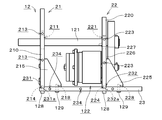
図11は、ナセルを外した本体部12の正面図である。図12は、ナセル125を外した本体部12の側面図である。風力発電装置10を組み立てる際には、まず、第1支持板本体210の下端部が、固定部23の前方溝部231内に配置され、ねじ孔214および前方溝部231の孔部231aにねじ128が挿入される。また、第1支持リブ215のねじ孔218および固定部23の孔部にねじ129が挿入される。
前方溝部231の内側壁と第1支持板本体210とを中心軸J1方向に当接させることにより、第1支持板21の中心軸J1方向の位置が正確に決定される。第1支持リブ215の下部は、固定部23の上面に当接する。これにより、第1支持板21を固定部23上に安定して配置することができる。
次に、第2支持板本体220の下端部が、固定部23の後方溝部232内に配置され、ねじ孔224および後方溝部232の孔部232aにねじ128が挿入される。また、第2支持リブ225のねじ孔228および固定部23の孔部にねじ129が挿入される。
後方溝部232の内側壁と第2支持板本体220とを中心軸J1方向に当接させることにより、第2支持板22の中心軸J1方向の位置が正確に決定される。第2支持リブ225の下部は、固定部23の上面に当接する。これにより、第2支持板22が固定部23上に安定して配置される。第2支持板22の固定部23への固定作業は、第1支持板21の固定部23への固定作業よりも先に行われてもよく、または、並行して行われてもよい。
次に、図9に示すように、第2支持板22の取付孔部222に、後端部に第2ギア52が取り付けられた発電機シャフト31が挿入され、突出部451aが取付孔部222に嵌り合う。第1支持孔211および第2支持孔221には、玉軸受126が挿入され、さらに、図12に示すように、風車シャフト121が挿入される。風車シャフト121の後端部には、第2ギア52と歯合するように第1ギア51が取り付けられる。図2に示すように、風車シャフト121の前端部および固定部23の後端部には、それぞれ、風車部11および尾翼部13が取り付けられる。風車部11および尾翼部13はそれぞれ、予め、風車シャフト121および固定部23に取り付けられてもよい。
次に、図1に示すナセル125が図12に示す第1支持板21および第2支持板22の外縁部上に配置される。ねじ130がナセル125を介して第1支持板21の側面のねじ孔213および第2支持板22の側面のねじ孔223に挿入される。これにより、ナセル125が第1支持板21および第2支持板22に固定される。さらに、別のねじ130がナセル125を介して固定部23のねじ孔234に挿入され、固定部23にナセル125の下部が固定される。
本体部12が構成された後、ポール14が固定部23に固定され、風力発電装置10の組み立てが終了する。
以上、風力発電装置10の構造および組み立ての流れについて説明したが、屋外に設置される風力発電装置10では、各部品のメンテナンスが必要となる。特に、伝達機構123の第1ギア51および第2ギア52は摩耗しやすく、これらの部品を定期的に交換する必要がある。伝達機構が第1支持板と第2支持板との間に存在する比較例の風力発電装置と図2の風力発電装置10とを比較する。この場合、比較例の風力発電装置では第1ギアや第2ギアを交換する際に、少なくともナセルおよび第2支持板を取り外す大掛かりな作業が必要となる。これに対し、風力発電装置10では、伝達機構123が、第2支持板22の後方に存在することから、ナセル125を取り外すのみにて第1ギア51および第2ギア52を取り外すことができる。このように、風力発電装置10では、伝達機構123のメンテナンスが容易となる。
また、第2支持板に固定された支持台上に発電機が設けられる比較例の風力発電装置と図2の風力発電装置10とを比較する。この場合、比較例の風力発電装置では第2支持板および支持台の姿勢を調整して発電機シャフトを水平にする必要がある。これに対し、風力発電装置10では、発電機122が第2支持板22に直接固定されるため、発電機シャフト31を容易に水平とすることができる。また、風車シャフト121は、前方部および後方部が第1支持板21および第2支持板22に支持される。これにより、容易に水平とすることができる。
加えて、発電機122が第2支持板22に直接固定されることから、風車シャフト121と発電機シャフト31との間の距離を容易かつ精度よく決定することができる。このように、風車シャフト121および発電機シャフト31が正確に水平かつ所定の間隔で配置されることにより、第1ギア51と第2ギア52との噛み合わせを高精度に行うことができる。その結果、ギア同士の噛み合わせ不良によるギアのきしみの発生や破損(寿命低下)を防止することができる。また、発電機122からの出力の低下を防止することができる。なお、発電機122は、第2支持板22に実質的に直接固定されるのであれば、発電機122と第2支持板22との間に薄い板やフィルム状の部材等が介在してもよい。
発電機122が第2支持板22に固定されることにより第2ギア52と発電機122との間の距離を短くすることができる。これにより、発電機122内の玉軸受431,432に作用する負荷を低減することができる。また、第2支持板22の中心軸J1方向の位置により発電機122の位置も決まるため、第2支持板22の位置を設計時に移動することにより、風力発電装置10の重心の位置を容易に変更することができる。
風力発電装置10では、発電機122が風車シャフト121に近接して配置されることにより、本体部12を小型化することができる。また、第1支持板21と第2支持板22との間に発電機122が配置されることにより、風車シャフト121を支持する2つの玉軸受126の間の距離を確保しつつ本体部12を小型化することができる。本体部12が小型化されることにより、本体部12近傍の気流の乱れが抑えられ、風車部11の回転速度の低下が防止される。
風力発電装置10は、伝達機構123を介して風車シャフト121と発電機シャフト31とが接続される、いわゆる、増速式である。これにより、風車部11の回転速度が低い場合であっても、回転部3を十分な回転速度にて回転させることができる。また、安定して発電を行うことができる。発電機122では、回転部3の回転速度が十分に確保されるため、伝達機構を有しない風力発電装置に比べてステータ41等を大きくすることなく高い出力が得られる。
発電機122が風車シャフト121に並列に配列される。これにより、風車シャフト121の延びる方向における本体部12の大きさを抑えることができる。その結果、ナセル125の製造コストを低減することができる。
本体部12では、図12に示すように、第2支持リブ225が、後方側の主面226、すなわち、第2支持板本体220の発電機122が取り付けられる主面227とは反対側の主面に取り付けられる。また、第1支持リブ215に垂直な方向から見た場合に、第1支持リブ215と発電機122とが離間している。このため、発電機122を図12における紙面に垂直な方向にずらして取り外す際に、第1支持リブ215および第2支持リブ225が、発電機122に干渉することが低減または防止される。
また、第2支持板22の上端が第1ギア51の上端よりも上方に位置し、かつ、風車シャフト121に垂直かつ水平な方向における第2支持板22の最大幅が、第1ギア51の同方向の幅よりも大きい。これにより、ナセル125を第2支持板22に取り付ける際に、ナセル125が第1ギア51に強く接触することが低減または防止される。取付孔部222の直径が、第2ギア52の外径よりも大きい。これにより、発電機シャフト31に第2ギア52を固定した状態にて、発電機122を第2支持板22に着脱することができる。発電機122が風車シャフト121の下方に位置することにより、発電機122を安定して第2支持板22にて支持することができる。
以上、本発明の実施形態について説明したが、本発明は上記実施形態に限定されるものではなく、様々な変更が可能である。
発電機122を安定して支持することができるのであれば、発電機122は風車シャフト121の上方にて第2支持板22に固定されてもよい。第1支持リブ215を含む第1支持板21は、一繋がりの部材でもよい。第2支持板22においても同様である。第2支持リブ225は、発電機122と干渉しないのであれば、第2支持板22の前方側の主面227に取り付けられてもよい。
第1ギア51は、金属にて形成されてもよい。第1支持板21の下端部に下方に突出する突起を設け、突起と固定部23の孔部とが嵌り合うことにより、第1支持板21の固定部23に対する位置決めが行われてもよい。第2支持板22においても同様である。
発電機122では、電磁ブレーキ以外のブレーキ機構を利用して回転部3の過度の回転が防止されてもよい。ブレーキ機能は省かれてもよい。発電機として、回転部が静止部の外側に位置するアウタロータ型が利用されてもよい。
上記実施形態および各変形例における構成は、相互に矛盾しない限り適宜組み合わされてよい。
本発明は、風力を利用して発電を行う風力発電装置として利用することができる。
10 風力発電装置
11 風車部
21 第1支持板
22 第2支持板
23 固定部
31 発電機シャフト
33 ロータマグネット
41 ステータ
51 第1ギア
52 第2ギア
111 ブレード
121 風車シャフト
122 発電機
123 伝達機構
125 ナセル
214 第1支持リブ
216 (第1支持板の)主面
222 取付孔部
224 第2支持リブ
226,227 (第2支持板の)主面
411 ステータコア
413 コイル
414 ティース
11 風車部
21 第1支持板
22 第2支持板
23 固定部
31 発電機シャフト
33 ロータマグネット
41 ステータ
51 第1ギア
52 第2ギア
111 ブレード
121 風車シャフト
122 発電機
123 伝達機構
125 ナセル
214 第1支持リブ
216 (第1支持板の)主面
222 取付孔部
224 第2支持リブ
226,227 (第2支持板の)主面
411 ステータコア
413 コイル
414 ティース
Claims (8)
- 水平方向を向く風車シャフトと、
前記風車シャフトの前方端に設けられ、前記風車シャフトに対して径方向外方へと延びる複数のブレードを有する風車部と、
前記風車部の後方にて、前記風車シャフトの前方部を支持する第1支持板と、
前記風車シャフトの後方部を支持する第2支持板と、
前記風車シャフトの上方または下方にて、前記第2支持板の前方側の主面に固定された発電機と、
前記風車シャフトからの動力を前記発電機に伝達する伝達機構と、
前記発電機、前記第2支持板および前記伝達機構を収容するナセルと、
を備え、
前記発電機が、
前記風車シャフトに平行な発電機シャフトと、
前記発電機シャフトと共に回転するロータマグネットと、
前記ロータマグネットに対向するステータと、
を備え、
前記ステータが、
積層鋼板であるステータコアと、
前記ステータコアのティースに設けられたコイルと、
を備え、
前記伝達機構が、
前記第2支持板の後方側にて前記風車シャフトに取り付けられた第1ギアと、
前記第1ギアよりも径が小さく、前記第2支持板の後方側にて、前記第2支持板を貫通する前記発電機シャフトに取り付けられ、前記第1ギアと歯合する第2ギアと、
を備える、風力発電装置。 - 前記発電機が、前記風車シャフトの下方に位置する、請求項1に記載の風力発電装置。
- 前記第2支持板の上端が、前記第1ギアの上端よりも上方に位置し、前記第2支持板の前記風車シャフトに垂直かつ水平な方向における最大幅が、前記第1ギアの同方向の幅よりも大きい、請求項1または2に記載の風力発電装置。
- 前記発電機シャフトが挿入される前記第2支持板の孔部の直径が、前記第2ギアの外径よりも大きい、請求項1ないし3のいずれかに記載の風力発電装置。
- 前記第1支持板の下部、および、前記第2支持板の下部が固定される固定部、をさらに備え、
前記第1支持板が、後方側の主面から後方に突出し、前記固定部の上面に当接する第1支持リブ、を備え、
前記第1支持リブに垂直な方向から見た場合に、前記第1支持リブと前記発電機とが離間している、請求項1ないし4のいずれかに記載の風力発電装置。 - 前記第2支持板が、後方側の主面から後方に突出し、前記固定部の上面に当接する第2支持リブ、を備える請求項5に記載の風力発電装置。
- 前記第1支持板の下部、および、前記第2支持板の下部が固定される固定部、をさらに備え、
前記第2支持板が、後方側の主面から後方に突出し、前記固定部の上面に当接する第2支持リブ、を備える請求項1ないし4のいずれかに記載の風力発電装置。 - 前記第1支持板により、前記ナセルの前部が閉塞される、請求項1ないし7のいずれかに記載の風力発電装置。
Priority Applications (1)
| Application Number | Priority Date | Filing Date | Title |
|---|---|---|---|
| CN201290000490.XU CN203655542U (zh) | 2011-05-10 | 2012-05-09 | 风力发电装置 |
Applications Claiming Priority (2)
| Application Number | Priority Date | Filing Date | Title |
|---|---|---|---|
| JP2011-105585 | 2011-05-10 | ||
| JP2011105585 | 2011-05-10 |
Publications (1)
| Publication Number | Publication Date |
|---|---|
| WO2012153750A1 true WO2012153750A1 (ja) | 2012-11-15 |
Family
ID=47139227
Family Applications (1)
| Application Number | Title | Priority Date | Filing Date |
|---|---|---|---|
| PCT/JP2012/061811 Ceased WO2012153750A1 (ja) | 2011-05-10 | 2012-05-09 | 風力発電装置 |
Country Status (2)
| Country | Link |
|---|---|
| CN (1) | CN203655542U (ja) |
| WO (1) | WO2012153750A1 (ja) |
Citations (3)
| Publication number | Priority date | Publication date | Assignee | Title |
|---|---|---|---|---|
| US4006925A (en) * | 1974-08-15 | 1977-02-08 | Peter Scherer | Wind power energy generating system |
| JP2002295362A (ja) * | 2001-03-28 | 2002-10-09 | Yasuhisa Choshoin | 風力発電装置 |
| EP2317137A1 (en) * | 2009-11-02 | 2011-05-04 | General Electric Company | Configuration of a wind turbine nacelle |
-
2012
- 2012-05-09 CN CN201290000490.XU patent/CN203655542U/zh not_active Expired - Fee Related
- 2012-05-09 WO PCT/JP2012/061811 patent/WO2012153750A1/ja not_active Ceased
Patent Citations (3)
| Publication number | Priority date | Publication date | Assignee | Title |
|---|---|---|---|---|
| US4006925A (en) * | 1974-08-15 | 1977-02-08 | Peter Scherer | Wind power energy generating system |
| JP2002295362A (ja) * | 2001-03-28 | 2002-10-09 | Yasuhisa Choshoin | 風力発電装置 |
| EP2317137A1 (en) * | 2009-11-02 | 2011-05-04 | General Electric Company | Configuration of a wind turbine nacelle |
Also Published As
| Publication number | Publication date |
|---|---|
| CN203655542U (zh) | 2014-06-18 |
Similar Documents
| Publication | Publication Date | Title |
|---|---|---|
| JP5557392B2 (ja) | アウターロータ・コアレス型風力発電機の発電機軸の固定構造 | |
| CN102037239B (zh) | 直接驱动发电机和风力涡轮机 | |
| CN102089517B (zh) | 风力涡轮机 | |
| JP5543371B2 (ja) | 同軸反転式コアレス発電機 | |
| EP2063114A1 (en) | Wind turbine | |
| JP2008546948A (ja) | 単一メインベアリングを有する風力発電機 | |
| JP5531113B2 (ja) | 縦軸可変形状式風力エネルギー収集装置 | |
| JP2011526986A (ja) | 風車 | |
| CN109931224A (zh) | 外转子式直驱风力发电机组 | |
| US8647224B2 (en) | Generator arrangement for a wind power plant | |
| US20120177492A1 (en) | Wind turbine | |
| CN102705164A (zh) | 风力发电设备 | |
| CN202017579U (zh) | 双盘式风力发电机 | |
| CN103122827B (zh) | 风力发电装置 | |
| WO2012153750A1 (ja) | 風力発電装置 | |
| CA2793447C (en) | Components for generators, their use and stator mounting | |
| JP2009281228A (ja) | 風力発電装置 | |
| JP2002303253A (ja) | 風力発電装置 | |
| KR20110089952A (ko) | 풍력발전용 멀티 터빈 | |
| JP2010151006A (ja) | アウターロータ・コアレス型風力発電機の発電機軸の固定構造 | |
| CN202384861U (zh) | 旋转电机及风力发电装置 | |
| CN101988476B (zh) | 风力发电机 | |
| CN205265392U (zh) | 内转子电机 | |
| CN202326008U (zh) | 风力发电装置 | |
| CN202659418U (zh) | 风力发电设备 |
Legal Events
| Date | Code | Title | Description |
|---|---|---|---|
| WWE | Wipo information: entry into national phase |
Ref document number: 201290000490.X Country of ref document: CN |
|
| 121 | Ep: the epo has been informed by wipo that ep was designated in this application |
Ref document number: 12781645 Country of ref document: EP Kind code of ref document: A1 |
|
| NENP | Non-entry into the national phase |
Ref country code: DE |
|
| 122 | Ep: pct application non-entry in european phase |
Ref document number: 12781645 Country of ref document: EP Kind code of ref document: A1 |
|
| NENP | Non-entry into the national phase |
Ref country code: JP |