WO2012147455A1 - 充電制御装置、テレビジョン受像機、および充電制御方法 - Google Patents
充電制御装置、テレビジョン受像機、および充電制御方法 Download PDFInfo
- Publication number
- WO2012147455A1 WO2012147455A1 PCT/JP2012/058850 JP2012058850W WO2012147455A1 WO 2012147455 A1 WO2012147455 A1 WO 2012147455A1 JP 2012058850 W JP2012058850 W JP 2012058850W WO 2012147455 A1 WO2012147455 A1 WO 2012147455A1
- Authority
- WO
- WIPO (PCT)
- Prior art keywords
- monitor
- battery
- charging
- secondary battery
- mode
- Prior art date
- Legal status (The legal status is an assumption and is not a legal conclusion. Google has not performed a legal analysis and makes no representation as to the accuracy of the status listed.)
- Ceased
Links
Images









Classifications
-
- H—ELECTRICITY
- H02—GENERATION; CONVERSION OR DISTRIBUTION OF ELECTRIC POWER
- H02J—ELECTRIC POWER NETWORKS; CIRCUIT ARRANGEMENTS OR SYSTEMS FOR SUPPLYING OR DISTRIBUTING ELECTRIC POWER; SYSTEMS FOR STORING ELECTRIC ENERGY
- H02J7/00—Circuit arrangements for charging or discharging batteries or for supplying loads from batteries
- H02J7/02—Circuit arrangements for charging or discharging batteries or for supplying loads from batteries for charging batteries from AC mains by converters
- H02J7/04—Regulation of charging current or voltage
-
- H—ELECTRICITY
- H02—GENERATION; CONVERSION OR DISTRIBUTION OF ELECTRIC POWER
- H02J—ELECTRIC POWER NETWORKS; CIRCUIT ARRANGEMENTS OR SYSTEMS FOR SUPPLYING OR DISTRIBUTING ELECTRIC POWER; SYSTEMS FOR STORING ELECTRIC ENERGY
- H02J7/00—Circuit arrangements for charging or discharging batteries or for supplying loads from batteries
- H02J7/60—Circuit arrangements for charging or discharging batteries or for supplying loads from batteries including safety or protection arrangements
-
- H—ELECTRICITY
- H02—GENERATION; CONVERSION OR DISTRIBUTION OF ELECTRIC POWER
- H02J—ELECTRIC POWER NETWORKS; CIRCUIT ARRANGEMENTS OR SYSTEMS FOR SUPPLYING OR DISTRIBUTING ELECTRIC POWER; SYSTEMS FOR STORING ELECTRIC ENERGY
- H02J7/00—Circuit arrangements for charging or discharging batteries or for supplying loads from batteries
- H02J7/80—Circuit arrangements for charging or discharging batteries or for supplying loads from batteries including monitoring or indicating arrangements
- H02J7/82—Control of state of charge [SOC]
-
- H—ELECTRICITY
- H02—GENERATION; CONVERSION OR DISTRIBUTION OF ELECTRIC POWER
- H02J—ELECTRIC POWER NETWORKS; CIRCUIT ARRANGEMENTS OR SYSTEMS FOR SUPPLYING OR DISTRIBUTING ELECTRIC POWER; SYSTEMS FOR STORING ELECTRIC ENERGY
- H02J7/00—Circuit arrangements for charging or discharging batteries or for supplying loads from batteries
- H02J7/875—Charging or discharging for charge maintenance, battery initiation or rejuvenation
-
- H—ELECTRICITY
- H02—GENERATION; CONVERSION OR DISTRIBUTION OF ELECTRIC POWER
- H02J—ELECTRIC POWER NETWORKS; CIRCUIT ARRANGEMENTS OR SYSTEMS FOR SUPPLYING OR DISTRIBUTING ELECTRIC POWER; SYSTEMS FOR STORING ELECTRIC ENERGY
- H02J7/00—Circuit arrangements for charging or discharging batteries or for supplying loads from batteries
- H02J7/90—Regulation of charging or discharging current or voltage
- H02J7/92—Regulation of charging or discharging current or voltage with prioritisation of loads or sources
-
- H—ELECTRICITY
- H02—GENERATION; CONVERSION OR DISTRIBUTION OF ELECTRIC POWER
- H02J—ELECTRIC POWER NETWORKS; CIRCUIT ARRANGEMENTS OR SYSTEMS FOR SUPPLYING OR DISTRIBUTING ELECTRIC POWER; SYSTEMS FOR STORING ELECTRIC ENERGY
- H02J7/00—Circuit arrangements for charging or discharging batteries or for supplying loads from batteries
- H02J7/90—Regulation of charging or discharging current or voltage
- H02J7/94—Regulation of charging or discharging current or voltage in response to battery current
- H02J7/947—Regulation of charging or discharging current or voltage in response to battery current in response to integrated charge or discharge current
-
- H—ELECTRICITY
- H01—ELECTRIC ELEMENTS
- H01M—PROCESSES OR MEANS, e.g. BATTERIES, FOR THE DIRECT CONVERSION OF CHEMICAL ENERGY INTO ELECTRICAL ENERGY
- H01M10/00—Secondary cells; Manufacture thereof
- H01M10/42—Methods or arrangements for servicing or maintenance of secondary cells or secondary half-cells
- H01M10/44—Methods for charging or discharging
-
- Y—GENERAL TAGGING OF NEW TECHNOLOGICAL DEVELOPMENTS; GENERAL TAGGING OF CROSS-SECTIONAL TECHNOLOGIES SPANNING OVER SEVERAL SECTIONS OF THE IPC; TECHNICAL SUBJECTS COVERED BY FORMER USPC CROSS-REFERENCE ART COLLECTIONS [XRACs] AND DIGESTS
- Y02—TECHNOLOGIES OR APPLICATIONS FOR MITIGATION OR ADAPTATION AGAINST CLIMATE CHANGE
- Y02E—REDUCTION OF GREENHOUSE GAS [GHG] EMISSIONS, RELATED TO ENERGY GENERATION, TRANSMISSION OR DISTRIBUTION
- Y02E60/00—Enabling technologies; Technologies with a potential or indirect contribution to GHG emissions mitigation
- Y02E60/10—Energy storage using batteries
Definitions
- the present invention relates to a charge control device, a television receiver, and a charge control method that can charge a secondary battery.
- Patent Document 1 in a secondary battery device including a battery remaining amount monitoring unit, power supply to the battery remaining amount monitoring unit is stopped by shutting off a switch circuit when the voltage of the secondary battery decreases. Techniques to do this are disclosed. According to this technique, since the current consumption of the battery remaining amount monitoring unit becomes 0, the internal current consumption of the secondary battery device can be reduced, and as a result, the battery driving time is prolonged.
- the life of the secondary battery tends to be shortened.
- the conventional technology even if the device is always connected to an AC outlet and the device is used with almost no battery drive, as long as power is supplied from an external power source, secondary power generated by this power can be used. The battery is always charged. Further, if the battery is not driven, the secondary battery is hardly discharged. As a result, the fully charged state of the secondary battery will continue for a long time. For this reason, the conventional technology cannot extend the life of the secondary battery.
- the present invention has been made in view of the above problems, and an object of the present invention is to prevent the occurrence of an event that shortens the life of the secondary battery such that the fully charged state of the secondary battery continues for a long period of time. This is to prolong the life of the secondary battery.
- a charging control device is a charging control device that controls charging of the secondary battery used in an apparatus that can be driven by both an external power source and a secondary battery, When power is supplied from the external power source to the device, a first mode in which main charging of the secondary battery is performed by power from the external power source, and power from the external power source to the device. And a second mode in which main charging of the secondary battery with electric power from the external power source is not performed even when being supplied.
- the secondary battery is set until the fully charged state is reached by setting the mode of the charging control device to the second mode. Can be kept from being charged. As a result, the secondary battery continues to be charged even though the device is not driven by the secondary battery for a long period of time, and the fully charged state that causes the deterioration does not continue for a long period of time. Therefore, the lifetime of the secondary battery can be extended.
- main charging indicates a charging mode in which the secondary battery is continuously charged until the battery is fully charged (the remaining battery level is 100% or substantially 100%). That is, a charging mode in which the remaining battery capacity of the secondary battery is increased as much as possible so that the driving time of the device by the secondary battery can be extended.
- charging modes other than “main charging” include “preliminary charging”.
- preliminary charging refers to a charging mode in which charging of the secondary battery is stopped before the battery is fully charged, and the remaining battery level of the secondary battery is suppressed to a predetermined value or less.
- the second mode may be a mode in which at least main charging is not performed, may be a mode in which no charging is performed on the secondary battery, or charging other than main charging, for example, a secondary battery May be a mode in which preliminary charging is performed.
- a television receiver according to the present invention is characterized by including the above-described charging control device.
- the television receiver can achieve the same effect as the above charge control device.
- the charge control method according to the present invention is a charge control method for controlling charging of the secondary battery used in a device that can be driven by both an external power source and a secondary battery,
- a first mode in which main charging of the secondary battery is performed by power from the external power source and when power is supplied from the external power source to the device. Even if it exists, it has the 2nd mode which does not perform the main charge of the said secondary battery by the electric power from the said external power supply.
- the charge control device executes the charge control method, the same effects as those of the charge control device can be obtained.
- the charging control device when power is supplied from an external power source to the device, main charging of the secondary battery by the power from the external power source
- the second mode in which the main charging is not performed and when the device is not driven by the secondary battery, the secondary battery is charged by setting the second mode. It can be prevented from continuing to do so. Thereby, the occurrence of an event that shortens the life of the secondary battery that the fully charged state of the secondary battery continues for a long period of time can be prevented, and the life of the secondary battery can be prolonged.
- the charge mode which the monitor concerning an embodiment has is shown. It is a flowchart which shows the procedure of the charge control process by the charge control part which concerns on embodiment. An example of the non-charge recommendation screen which the monitor concerning an embodiment displays is shown. An example of the discharge recommendation screen which the monitor which concerns on embodiment displays is shown. It is a flowchart which shows the procedure of the precharge control process by the charge control part which concerns on embodiment.
- An example of the preliminary charging operation by the monitor according to the embodiment is shown. It is a figure which shows the transition of the power supply state of the monitor and STB which concern on embodiment. It is a figure which shows the relationship between the state transition of the power supply of the monitor which concerns on embodiment, and the state transition of the power supply of STB.
- An example of the battery status icon which the monitor concerning an embodiment displays is shown.
- the example of a display of the battery status icon by the monitor concerning an embodiment is shown.
- An example of the battery remaining amount warning screen which the monitor which concerns on embodiment displays is shown.
- An example of the battery remaining amount warning screen which the monitor which concerns on embodiment displays is shown.
- the correspondence of the charge condition of the battery in the monitor which concerns on embodiment, and the lighting pattern of an indicator is shown.
- the setting of the brightness of the display in the monitor which concerns on embodiment is shown. It is a block diagram which shows the modification of the structure of the power supply part which concerns on embodiment. An example of the discharge confirmation screen which the monitor concerning an embodiment displays is shown. It is a block diagram which shows the modification of the structure of the monitor which concerns on embodiment. It is a flowchart which shows the modification of the procedure of the charge control process by the charge control part which concerns on embodiment.
- TV 100 a television receiving system (hereinafter abbreviated as “TV”) 100 according to the present embodiment will be described.
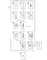
- FIG. 1 is a diagram illustrating a device configuration of a television 100 according to the embodiment.
- the television 100 shown in FIG. 1 receives various contents transmitted as a broadcast wave of a digital television broadcast or a broadcast wave of a BS digital broadcast by a corresponding tuner (digital television tuner or BS digital tuner) and reproduces the content. This is a so-called television receiver.
- the television 100 includes a monitor 110 and an STB (set top box) 120.
- STB 120 has a built-in tuner for receiving terrestrial digital broadcasting and BS broadcasting.
- the STB 120 acquires the content received by the DTV / BS antenna 130 using this tuner.
- the STB 120 encrypts the acquired content using a DRM (Digital Rights Management) technology.
- the STB 120 transmits the obtained encrypted data to the monitor 110 by wireless communication.
- the monitor 110 receives and decrypts the encrypted data transmitted from the STB 120. Then, the monitor 110 displays the obtained content on the display.
- DRM Digital Rights Management
- the communication between the STB 120 and the monitor 110 is preferably wireless communication so that the present embodiment employs wireless communication. Thereby, the freedom degree of the place which installs the monitor 110 increases. This makes it possible to install the monitor 110 at an arbitrary location within an area where wireless communication with the STB 120 is possible.
- a communication standard suitable for wireless communication between the STB 120 and the monitor 110 includes, for example, the IEEE 802.11 series.
- External devices can be connected to the STB 120 and the monitor 110.
- the STB 120 can record the content on the recorder 132 connected to the STB 120, or can encrypt the content reproduced by the recorder 132 and transmit it to the monitor 110.
- the monitor 110 can record the content on the recorder 133 connected to the monitor 110 and display the content reproduced by the recorder 133 on the display.
- communication standards suitable for wired communication between the STB 120 and an external device and wired communication between the monitor 110 and the external device include, for example, HDMI (High Definition Multimedia Interface) (registered trademark). It is done.
- a liquid crystal display is used as the monitor 110, but other than this, an organic EL display, a plasma display, a cathode ray tube display, or the like may be used.
- FIG. 2 is a block diagram illustrating a configuration of the monitor 110 according to the embodiment.
- the monitor 110 includes a wireless LAN module 212, a demultiplexer 213, a DRM decoding unit 214, a control circuit 240, a panel controller 218, a display 219, H.264, and the like.
- the wireless LAN module 212 is a communication interface for wireless communication.
- a reception signal received by the wireless LAN module 212 is supplied to the demultiplexer 213.
- the demultiplexer 213 separates the encrypted data from the received signal.
- the encrypted data separated by the demultiplexer 213 is supplied to the DRM decryption unit 214.
- the DRM decryption unit 214 obtains a video signal by decrypting the encrypted data.
- the video signal obtained by the DRM decoding unit 214 is supplied to the control circuit 240.
- the control circuit 240 is constituted by a CPU, ROM, RAM, and the like, and controls each part of the monitor 110 by the CPU executing a program recorded in the ROM, RAM, and the like.
- the control circuit 240 superimposes an OSD (On-screen Display) display on the video represented by the video signal or performs image quality correction (gamma curve control, contrast control, etc.).
- the video signal processed by the control circuit 240 is supplied to the panel controller 218.
- the panel controller 218 drives, for example, a liquid crystal panel constituting the display 219 based on the processed video signal.
- the control circuit 240 converts the video signal obtained by the DRM decoding unit 214 into the H.264 format. Also supplied to the H.264 encoding / decoding unit 215. H. The H.264 encoding / decoding unit 215 encodes this video signal to obtain encoded data. H. The encoded data obtained by the H.264 encoding / decoding unit 215 is supplied to the HDMI transceiver / receiver 216. The HDMI transceiver / receiver 216 transmits the encoded data to the recorder 133.
- the HDMI transceiver / receiver 216 receives the encoded data from the recorder 133.
- the H.264 encoding / decoding unit 215 obtains a video signal by decoding the encoded data.
- the video signal obtained by the H.264 encoding / decoding unit 215 is supplied to the panel controller 218 via the control circuit 240.
- the panel controller 218 drives the liquid crystal panel constituting the display 219 based on this video signal.
- the power supply unit 224 supplies power necessary for the operation to each unit of the monitor 110.
- the indicator 220 lights up under the control of the control circuit 240. Thereby, the indicator 220 notifies the user of the state of the monitor 110 and the like.
- the monitor 110 has a remote control 250 including a power button and a remote control light receiving unit 252 that receives infrared light emitted by the remote control 250.
- the main body of the monitor 110 is provided with operation buttons 260 including a power button.
- the user operates the remote controller 250 or the operation buttons 260 to perform operations such as power ON / OFF, volume adjustment, input switching, channel selection, various settings, recording, and playback on the television 100. Can do.
- control circuit 240 has functions as a charge control unit, a power supply state switching unit, and a battery state notification unit. Details of each function will be described later.
- FIG. 3 is a block diagram illustrating a configuration of the STB 120 according to the embodiment.
- the STB 120 includes a tuner 302, a demodulator 304, a demultiplexer 306, a control circuit 340, a DRM encryption unit 308, a wireless LAN module 310, and an H.264.
- the tuner 302 receives a digital TV broadcast wave or a BS digital broadcast wave from the DTV / BS antenna 130.
- the video data received by the tuner 302 is supplied to the demodulator 304.
- the demodulator 304 demodulates the video data.
- the video data demodulated by the demodulator 304 is supplied to the demultiplexer 306.
- the demultiplexer 306 separates the video signal from the video data.
- the video signal separated by the demultiplexer 306 is supplied to the control circuit 340.
- the control circuit 340 includes a CPU, ROM, RAM, and the like, and controls each part of the STB 120 when the CPU executes a program recorded in the ROM, RAM, and the like.
- the control circuit 340 superimposes an OSD (On-screen Display) display on the video represented by the video signal or performs image quality correction (gamma curve control, contrast control, etc.).
- OSD On-screen Display
- the video signal processed by the control circuit 340 is supplied to the DRM encryption unit 308.
- the DRM encryption unit 308 obtains encrypted data by encrypting the video signal.
- the encrypted data obtained by the DRM encryption unit 308 is supplied to the wireless LAN module 310.
- the wireless LAN module 310 is a communication interface for wireless communication.
- the wireless LAN module 310 transmits the encrypted data to the monitor 110.
- the control circuit 340 converts the video signal obtained by the demultiplexer 306 into the H.264 format. Also supplied to the H.264 encoding / decoding unit 312. H. The H.264 encoding / decoding unit 312 encodes this video signal to obtain encoded data. H. The encoded data obtained by the H.264 encoding / decoding unit 215 is supplied to the HDMI transceiver / receiver 314. The HDMI transceiver / receiver 314 transmits the encoded data to the recorder 132.
- the HDMI transceiver / receiver 314 receives the encoded data from the recorder 132.
- the H.264 encoding / decoding unit 312 obtains a video signal by decoding the encoded data.
- the video signal obtained by the H.264 encoding / decoding unit 312 is supplied to the DRM encryption unit 308 via the control circuit 340.
- the DRM encryption unit 308 obtains encrypted data by encrypting the video signal.
- the encrypted data obtained by the DRM encryption unit 308 is supplied to the wireless LAN module 310.
- the wireless LAN module 310 transmits the encrypted data to the monitor 110.
- the power supply unit 324 supplies power necessary for its operation to each unit of the STB 120.
- the indicator 320 is turned on under the control of the control circuit 340. Thereby, the indicator 320 notifies the user of the state of the STB 120 and the like.
- an operation button 350 including a power button is provided on the main body of the STB 120.
- the user can perform operations such as power ON / OFF for the STB 120 by operating the operation buttons 350.
- the control circuit 340 has a function as a power supply state switching unit. Details of this function will be described later.
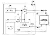
- FIG. 4 is a block diagram illustrating a specific configuration of the power supply unit 224 according to the embodiment.
- the power supply unit 224 includes a battery unit 402, an AC adapter 404, a charging circuit 406, a switch 408, and a switch 410.
- the AC adapter 404 is provided outside the main body of the monitor 110.
- the AC adapter 404 can be detached from the main body of the monitor 110.
- the battery unit 402, the charging circuit 406, the switch 408, and the switch 410 are built in the main body of the monitor 110.
- connection line indicated by a solid line indicates a supply path of electric power supplied from the power supply (AC adapter 404 or battery unit 402).
- connection lines indicated by dotted arrows indicate transmission paths for various control signals.
- the AC adapter 404 (external power source) is connected to an AC outlet and supplies power for driving the monitor 110 and charging the battery unit 402.
- the battery unit 402 (secondary battery) supplies power for driving the monitor 110.
- the monitor 110 can be operated by electric power supplied from the battery unit 402.
- the monitor 110 is provided with a power input terminal to which an AC adapter 404 (external power supply) is connected.
- the monitor 110 can also be operated by power supplied from the AC adapter 404 via the power input terminal.
- the monitor 110 has a function as a charging device, and can charge the battery unit 402 with the power supplied from the AC adapter 404.
- the charging circuit 406 charges the battery unit 402 using the power supplied from the AC adapter 404.
- the switch 408 switches the connection destination between the power supply path from the AC adapter 404 and the power supply path from the battery unit 402, thereby changing the power supply source for driving the monitor 110 from the AC adapter 404. Switching with the battery unit 402.
- the switch 410 is provided on the power supply path from the battery unit 402, and connects / disconnects the supply path when turned on / off.
- the charge control unit of the control circuit 240 controls the charging of the battery unit 402 by the power supplied from the AC adapter 404. Specifically, the charging control unit controls charging of the battery unit 402 by controlling the charging circuit 406, the switch 408, and the switch 410. Specific control by the charge control unit will be described with reference to FIG.
- the monitor 110 has a plurality of charging modes.
- the charging control unit varies the charging operation of the battery unit 402 according to the charging mode.
- FIG. 5 shows a charging mode of the monitor 110 according to the embodiment.
- the monitor 110 of the present embodiment has “mode 1” (first mode) and “mode 2” (second mode) as charging modes.
- “Mode 1” is a mode in which, when power is supplied from the AC adapter 404, the battery unit 402 is charged using this power.
- “mode 2” is a mode in which the battery unit 402 is not charged even when power is supplied from the AC adapter 404.
- the monitor 110 can be driven by the power supplied from the AC adapter 404 and can stand by without being driven by the power supplied from the AC adapter 404.
- the charging control unit causes the charging circuit 406 to perform main charging of the battery unit 402 by the power from the AC adapter 404 by switching on the main charging function of the charging circuit 406.
- the main charging function of the charging circuit 406 is switched off, so that the main charging of the battery unit 402 by the power from the AC adapter 404 is not performed by the charging circuit 406.
- the setting of which of the plurality of charging modes is valid is stored in a recording medium such as a memory provided in the monitor 110 as setting information indicating the content.
- a recording medium such as a memory provided in the monitor 110 as setting information indicating the content.
- the user can select and enable any charging mode of “mode 1” or “mode 2”.
- the charging control unit reads the setting information to determine in which charging mode to operate.
- the charging control unit displays a screen (hereinafter referred to as “non-charging recommendation screen”) indicating that it is recommended not to charge the battery unit 402 so that the fully charged state of the secondary battery does not continue for a long time. Is displayed on the display 219. That is, the charge control unit has a function as a first notification unit.
- the charging control unit displays a screen (hereinafter, referred to as a “recommended discharge screen”) on which a message indicating that it is recommended to discharge the battery unit 402 is displayed on the display 219. That is, the charge control unit has a function as a second notification unit.
- the charging control unit displays a non-charging recommendation screen on the display 219. To do.
- the charge control unit displays a non-charge recommendation screen on the display 219 when the battery unit 402 is being charged even though the battery is not driven for a predetermined period.
- the predetermined period is “30 days”, but is not limited thereto.
- the charge control unit displays a discharge recommendation screen. 219.
- the charging control unit displays a non-charging recommendation screen on the display 219 when the remaining battery level of the battery unit 402 exceeds a predetermined value even though the battery unit 402 has not been charged for a predetermined period.
- the predetermined period is “14 days”, but the present invention is not limited to this.
- FIG. 6 is a flowchart illustrating a procedure of charge control processing by the charge control unit according to the embodiment.
- the charge control unit determines whether or not to charge the battery unit 402 by reading the charge mode setting (step S602). Specifically, if “mode 1” is set as the charge mode, it is determined that the battery unit 402 should be charged. If “mode 2” is set as the charge mode, the battery unit 402 is charged. Judge that you should not do.
- step S602 when it is determined that the battery unit 402 should be charged (step S602: Yes), the charging control unit determines whether the AC adapter 404 is connected (step S604).
- step S604 When it is determined in step S604 that the AC adapter 404 is not connected (step S604: No), the charging control unit indicates a period during which the battery unit 402 is fully charged by the timer function (hereinafter referred to as “full charging period”). .) Is cleared (step S614), and the charge control process is terminated.
- step S604 determines whether the AC adapter 404 is connected (step S604: Yes)
- the charging control unit continues to charge the battery unit 402 using the power supplied from the AC adapter 404. (Step S606), the full charge period is continuously measured by the timer function (Step S608).
- step S606 if charging has not yet started, the process in step S606 is “start charging the battery unit 402".
- step S608 if the measurement has not yet started, the process in step S608 is “start measurement of the full charge period by the timer function”.
- the charge control unit determines whether or not the full charge period measured by the timer function has passed 30 days (step S610).
- step S610 When it is determined in step S610 that the full charge period has passed 30 days (step S610: Yes), the charge control unit displays a non-charge recommendation screen as shown in FIG. 7 on the display 219 (step S612). And a charge control part clears measurement of the full charge period by a timer function (step S614), and complete
- step S610 determines whether the full charge period has not passed 30 days (step S610: No).
- step S602 determines whether the remaining battery level of the battery unit 402 exceeds a predetermined value (step S620). ).
- step S620 When it is determined in step S620 that the remaining battery level does not exceed the predetermined value (step S620: No), the charge control unit clears the measurement of the full charge period by the timer function (step S628), and the charge control process Exit.
- step S620 when it is determined in step S620 that the remaining battery level exceeds the predetermined value (step S620: Yes), the charge control unit continues to measure the full charge period using the timer function (step S622). And a charge control part judges whether the full charge period measured by the timer function passed 14 days (step S624).
- step S624 When it is determined in step S624 that the full charge period has passed 14 days (step S624: Yes), the charge control unit displays a discharge recommendation screen as shown in FIG. 8 on the display 219 (step S626). And a charge control part clears measurement of the full charge period by a timer function (step S628), and complete
- step S624 when it is determined in step S624 that the full charge period has not passed 14 days (step S624: No), the charge control unit ends the charge control process.
- the charge controller repeats the above charge control process. Accordingly, it is possible to prompt the user not to fully charge the battery unit 402 and to discharge the battery unit 402 in a timely manner.
- the charge control unit may repeatedly perform the above process or may perform it at a predetermined timing.
- the predetermined timing includes, for example, a timing for switching the power supply state from “ON” to “OFF” or “STBY (standby)”, and a power supply state from “OFF” or “STBY (standby)” to “ON”. Timing to switch to can be adopted.
- FIG. 7 shows an example of a non-charge recommendation screen displayed on the monitor 110 according to the embodiment.
- a screen 700 shown in FIG. 7 is a non-charge recommendation screen.
- a message indicating that it is recommended not to charge the battery unit 402 is displayed.
- the monitor 110 displays the screen 700 on the display 219 when the battery unit 402 is being charged for a predetermined period.
- the screen 700 includes a button 702 and a button 704 for selecting whether or not to charge the battery unit 402.
- the monitor 110 keeps the charging mode “mode 1” so that the main charging of the battery unit 402 is continued.
- the monitor 110 switches the charging mode to “mode 2” so that the main charging of the battery unit 402 is not performed thereafter.
- FIG. 8 shows an example of a discharge recommendation screen displayed on the monitor 110 according to the embodiment.
- a screen 800 shown in FIG. 8 is a discharge recommendation screen.
- a message to recommend discharging of the battery unit 402 is displayed.
- the monitor 110 displays the screen 800 on the display 219 when a state in which the remaining battery level of the battery unit 402 is equal to or greater than a predetermined value continues for a predetermined period.
- the user confirming the content of the message shown on the screen 800 removes the AC adapter 404 from the monitor 110 or the AC outlet according to this message, and switches the monitor 110 to battery operation, thereby discharging the battery unit 402. be able to.
- the monitor 110 notifies the user of a message not to charge the battery unit 402 when the state in which the battery unit 402 is charged continues for a predetermined period. .
- a message to discharge the battery unit 402 is notified to the user.
- Preliminary charging is charging for preventing the battery unit 402 from being discharged too much.
- the preliminary charging of the battery unit 402 is controlled by the charging control unit.
- the monitor 110 when the remaining battery level of the battery unit 402 is within a predetermined range, the monitor 110 performs preliminary charging for preventing the battery remaining level from further decreasing. In particular, the monitor 110 starts the preliminary charging when the remaining battery level of the battery unit 402 decreases to the lower limit value of the above range. That is, even if the remaining battery level of the battery unit 402 is within the above range, if it has not decreased to the lower limit value, the preliminary charging is not started.
- the lower limit value of the above range is “0%”, and the upper limit value of the above range is “8%”.
- “0%” corresponds to an end-of-discharge voltage, and does not mean that the output voltage of the battery unit becomes 0V.
- the upper limit value is set as high as possible at a level at which the battery remaining amount icon display (see FIG. 13) does not change, so that preliminary charging can be performed without making the user aware of it.
- the monitor 110 performs preliminary charging only when the power supply is “ON”.
- FIG. 9 is a flowchart showing the procedure of the preliminary charging control process by the charging control unit.
- the charging control unit determines whether or not “preliminary charging” is set in the preliminary charging status indicating whether or not preliminary charging is being performed (step S902).
- step S902 determines whether the remaining battery level of the battery unit 402 is 0% (step S902). S904).
- step S904 when it is determined that the remaining battery level is not 0% (step S904: No), the charging control unit ends the preliminary charging control process.
- step S904 determines whether the monitor 110 is powered on (step S906).
- step S906 If it is determined in step S906 that the power is not on (step S906: No), the charge control unit ends the preliminary charge control process.
- step S906 when it is determined in step S906 that the power is on (step S906: Yes), the charging control unit starts precharging the battery unit 402 (step S908). Then, the charging control unit sets a charging voltage and a charging current for precharging the battery unit 402 (steps S910 and S912), and sets “preliminary charging” in the precharging status (step S914). The charge control process ends.
- step S902 when it is determined that “preliminary charging” is set (step S902: Yes), the charging control unit determines whether or not the remaining battery level of the battery unit 402 is 8% or more ( Step S920).
- step S920 When it is determined in step S920 that the remaining battery level is 8% or more (step S920: Yes), the charge control unit advances the process to step S924.
- step S920 determines whether the monitor 110 is powered on (step S920: No). Step S922).
- step S922 If it is determined in step S922 that the power is ON (step S922: Yes), the charge control unit ends the preliminary charge control process.
- step S922 determines that the power is not turned on (step S922: No)
- the charge control unit advances the process to step S924.
- step S924 the charging control unit sets the charging voltage to 0 V in order to end the preliminary charging of the battery unit 402 (step S924). At the same time, the charging control unit sets the charging current to 0 mA in order to end the preliminary charging of the battery unit 402 (step S926).
- the charging control unit ends the preliminary charging of the battery unit 402.
- FIG. 10 shows an example of the preliminary charging operation by the monitor 110 according to the embodiment.
- the monitor 110 of the present embodiment provides a spare for the battery unit 402 so that the remaining battery level of the battery unit 402 is maintained between 0% (lower limit value) and 8% (upper limit value). Charge the battery.
- the monitor 110 starts precharging the battery unit 402 when the remaining battery level of the battery unit 402 decreases to 0% due to natural discharge.
- the monitor 110 performs preliminary charging only when the power supply is “ON”. Therefore, as shown at the timing t4 in FIG. 10, the monitor 110 starts the preliminary charging of the battery unit 402, and the power state is “OFF” even if the remaining battery level of the battery unit 402 does not rise to 8%. ”Or“ STBY (standby) ”, the preliminary charging of the battery unit 402 ends.
- the monitor 110 has a table indicating the correspondence between the output voltage (V) of the battery unit 402 and the remaining battery level (mAh).
- the monitor 110 estimates the remaining battery level of the battery unit 402 from the output voltage of the battery unit 402 by referring to this table.
- the method for obtaining the remaining battery level of the battery unit 402 is not limited to the above.
- the monitor 110 may obtain the remaining battery level by inquiring the remaining battery level of the battery unit 402. .
- the monitor 110 performs the preliminary charging for preventing the battery remaining amount of the battery unit 402 from further decreasing when the remaining battery amount of the battery unit 402 is within a predetermined range. It was decided to do.
- the remaining battery level of the battery unit 402 can be maintained so that the battery unit 402 is not completely discharged.
- the battery unit 402 does not become a complete discharge state that causes its deterioration, and thus the life of the battery unit 402 can be extended.
- the monitor 110 of the present embodiment starts precharging the battery unit 402 when the remaining battery level of the battery unit 402 decreases to the lower limit of the above range.
- the control circuit 240 of the monitor 110 has not only a function as a charge control unit but also functions as a power supply state switching unit and a battery state notification unit. Further, the control circuit 230 of the STB 120 has a function as a power supply state switching unit.
- the function of the monitor 110 as a power supply state switching unit and the function of the STB 120 as a power supply state switching unit will be described.
- the power state switching unit of the monitor 110 switches the power state of the monitor 110. Specifically, the power state switching unit of the monitor 110 switches the power state of the monitor 110 in response to the user pressing a power button provided on the remote controller 250 or the main body.
- the power state switching unit of the STB 120 switches the power state of the STB 120. Specifically, the power state switching unit of the STB 120 switches the power state of the STB 120 in response to the user pressing a power button provided on the main body of the STB 120.
- the power state switching unit of the STB 120 can also switch the power state of the STB 120 in conjunction with the switching of the power state of the monitor 110. Specifically, when the power supply state switching unit of the monitor 110 switches the power supply state of the monitor 110, the control signal is transmitted to the STB 120 via wireless communication. When receiving the control signal, the power supply state switching unit of the STB 120 switches the power supply state of the STB 120 according to the contents of the control signal (that is, how the power supply state is switched in the monitor 110).
- the power state of the monitor 110 includes “ON”, “OFF”, and “STBY (standby)”. “ON” is a state in which the display 219 is driven and content can be viewed. “OFF” and “STBY (standby)” are states in which the display 219 is stopped and the content cannot be viewed.
- “STBY (standby)” is automatically turned “ON” when the viewing start time arrives, and the TV program can be viewed.
- “OFF” does not automatically turn the power “ON” even when the viewing start time comes.
- the power state of the monitor 110 is indicated by an indicator 220 (LED illumination) provided on the main body.
- an indicator 220 LED illumination
- the indicator 220 is lit in green.
- the power supply is “STBY (standby)” and the viewing reservation is set
- the indicator 220 is lit in orange.
- the power source is “STBY (standby)” and the viewing reservation is not set
- the indicator 220 is lit red.
- the power is “OFF”, the indicator 220 is not lit.
- the power state of the STB 120 includes “ON”, “OFF”, and “STBY (standby)”. “ON” is a state in which a series of operations for viewing content such as reception of broadcast waves and transmission of video signals is possible. “OFF” and “STBY (standby)” are states in which the series of operations cannot be performed.
- STBY (standby) accepts both a power switching operation in conjunction with the monitor 110 and a power switching operation by a power button provided on the main body of the STB 120.
- “OFF” does not accept a power supply switching operation in conjunction with the monitor 110, but accepts only a power supply switching operation by a power button provided on the STB 120 main body.
- the power state of the STB 120 is indicated by an indicator 320 (LED illumination) provided on the main body. For example, when the power is “ON”, the indicator 320 is lit in green. When the power supply is “STBY (standby)” and the recording reservation is set, the indicator 320 is lit in orange. When the power source is “STBY (standby)” and the recording reservation is not set, the indicator 320 is lit red. For example, when the power is “OFF”, the indicator 320 is not lit.
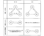
- FIG. 11 is a diagram illustrating transition of the power state of the monitor 110 and the STB 120 according to the embodiment.
- the power state switching unit of the monitor 110 performs different switching operations depending on the power state of the monitor 110 at that time.
- the power state switching unit of the monitor 110 performs different switching operations depending on whether the user presses the power button on the remote controller 250 or the power button on the main body. .
- the power state switching unit of the monitor 110 switches the power state of the monitor 110 to “ON”, “OFF”, or “STBY (standby)”.
- the power state switching unit of the monitor 110 switches the power state of the monitor 110 to “ON” or “STBY (standby)”.
- the operation of the remote controller 250 cannot switch the power state of the monitor 110 to “OFF”.
- the power state switching unit of the monitor 110 switches the power state of the monitor 110, it performs a different switching operation depending on the power switch mode setting set at that time.
- mode 1 (Power switch mode)
- mode 2 can be set in the monitor 110 as the power switch mode.
- Mode 1 is a mode in which switching to “OFF” by the power button of the main body is prohibited.
- Mode 2 is a mode that permits switching to “OFF” by the power button of the main body.
- the power state switching unit of the monitor 110 changes the power state to “STBY ( Switch to standby.
- the setting of the power switch mode is stored in a recording medium such as a memory provided in the monitor 110 as setting information indicating the contents, and the user can set an arbitrary mode in the setting information.
- the power state switching unit of the STB 120 performs different switching operations when the user presses a power button provided on the main body and when a control signal is received from the monitor 110. Do.
- the power state switching unit of the STB 120 switches the power state of the STB 120 to “ON” or “OFF”.
- the power state switching unit of the STB 120 switches the power state of the STB 120 to “ON” or “STBY (standby)”.
- the power state of the STB 120 is not switched to “OFF”.
- the STB 120 can switch the power state in conjunction with the monitor 110.
- the specific operation will be described with reference to FIG.
- FIG. 12 is a diagram illustrating a relationship between the power state transition of the monitor 110 and the power state transition of the STB 120 according to the embodiment.
- the power supply state transition of the STB 120 is determined for each power supply state transition pattern of the monitor 110.
- the power state of the STB 120 is switched according to this setting. As shown in FIG. 12, the power state of the STB 120 is switched to “ON” or “STBY (standby)” depending on the linkage with the monitor 110, but is not switched to “OFF”.
- the transition of the power state of the STB 120 shown in FIG. 12 is based on the premise that the power state of the STB 120 is the state before the transition shown here.
- the transition of the power state of the STB 120 does not occur.
- the STB 120 does not perform a power source switching operation.
- the STB 120 periodically performs wireless communication with the monitor 110 for confirming communication connection. For example, the STB 120 performs the wireless communication every 3 seconds. The power supply state switching unit of the STB 120 monitors this wireless communication. Then, the power supply state switching unit of the STB 120 switches the power supply state of the STB 120 to “STBY (standby)” when detecting an abnormality in the wireless communication.
- the STB 120 retries the wireless communication to the monitor 110 even after being switched to “STBY (standby)”.
- the monitor 110 normally receives the wireless communication by the retry, the monitor 110 transmits a control signal for switching the power supply state to “ON” to the STB 120.
- the power state switching unit of the STB 120 switches the power state of the STB 120 to “ON”.
- the STB 120 does not perform the above operation when communication is abnormal during pairing.
- “pairing” indicates an operation for linking devices as communication partners. For example, when the product is shipped, the monitor 110 and the STB 120 are not associated with each other. Therefore, by performing pairing between the monitor 110 and the STB 120, the monitor 110 and the STB 120 are associated with each other as communication partners and can communicate with each other.
- the battery state notification unit of the monitor 110 notifies the user of the charge state of the battery unit 402 and the remaining battery level.
- a notification example of the state of charge of the battery unit 402 and the remaining battery level under the control of the battery state notification unit of the monitor 110 will be specifically described.
- the monitor 110 displays on the display 219 an icon indicating the state of charge of the battery unit 402 and the remaining battery level (hereinafter referred to as “battery state icon”).
- FIG. 13 shows an example of a battery status icon displayed on the monitor 110 according to the embodiment.
- the monitor 110 displays a battery state icon showing the state of charge and the remaining battery level so that the user can recognize the state of charge and the remaining battery level of the battery unit 402.
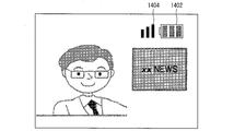
- FIG. 14 shows a display example of the battery status icon by the monitor 110 according to the embodiment.
- an icon 1402 and an icon 1404 are displayed side by side in the upper right of the screen of the display 219.
- Icon 1402 is a battery status icon.
- An icon 1404 is an icon indicating the reception strength of wireless communication.
- the monitor 110 may always display the battery status icon on the display 219. Further, the monitor 110 may switch between displaying and not displaying the battery status icon based on some setting or condition.
- the user it is possible to make the user set in advance whether or not to display the battery status icon, and to switch between displaying and not displaying the battery status icon based on this setting. Further, whether or not to display the battery status icon may be switched according to the type of screen displayed on the display 219.
- the monitor 110 does not display the battery status icon when the battery unit 402 is not being charged or used.
- the monitor 110 displays a screen (hereinafter, referred to as “battery remaining amount warning screen”) indicating a predetermined message indicating that fact on the display 219. .
- the monitor 110 is provided with a plurality of the predetermined values stepwise.
- the monitor 110 displays a predetermined battery remaining amount warning screen on the display 219 each time the remaining battery level of the battery unit 402 falls below the predetermined values.
- 5%, 3%, and 1% are set in the monitor 110 as the predetermined value. That is, the monitor 110 displays a predetermined battery remaining amount warning screen on the display 219 every time the remaining battery level of the battery unit 402 falls below 5%, 3%, and 1%.
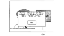
- the screen 1500 shown in FIG. 15 is a battery remaining amount warning screen displayed when the remaining battery level of the battery unit 402 falls below 5% or 3%, and the remaining battery level of the battery unit 402 decreases. Therefore, a message prompting you to connect the power cord is shown.
- the monitor 110 When the monitor 110 is driven by a battery and the remaining battery level of the battery unit 402 falls below 5%, the monitor 110 displays the remaining battery level warning screen shown in FIG.
- the monitor 110 further displays the remaining battery level warning screen shown in FIG.
- the monitor 110 similarly displays a battery remaining amount warning screen shown in FIG. 15 on the display 219 even when the battery remaining amount of the battery unit 402 is lower than 5% when the power is switched on. .
- the monitor 110 deletes the display of the battery remaining amount warning screen.
- (1) When a predetermined time has elapsed.
- the monitor 110 employs 15 seconds as the predetermined time, but is not limited to this.
- (2) When the user performs a predetermined operation meaning that the message has been confirmed (for example, when the “Confirm” button shown in FIG. 15 is pressed).
- (3) When the remaining battery level of the battery unit 402 further decreases during display, and the next remaining battery level warning screen is displayed. (4) When the supply of external power is started.
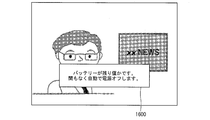
- a screen 1600 shown in FIG. 16 is a battery remaining amount warning screen that is displayed when the remaining battery level of the battery unit 402 is lower than 1%. A message is displayed informing you that will automatically turn off.
- the monitor 110 displays the battery level warning screen shown in FIG. To do.
- the monitor 110 erases the display of the remaining battery amount warning screen when it corresponds to either of the following (5) and (6).
- the monitor 110 employs 15 seconds as the predetermined time, but is not limited to this.
- (6) When the supply of external power is started.
- the monitor 110 has a function of automatically turning off the power when the battery level of the battery unit 402 is low.
- the monitor 110 automatically detects that the remaining battery level of the battery unit 402 is less than 1% and displays the message shown in FIG. Turn off the power automatically.
- the power state at this time transitions in the same manner as when the power button of the main body is pressed when the power state of the monitor 110 is “ON” as shown in FIG. That is, when “mode 1” is set, the power supply state is switched to “STBY (standby)”, and when “mode 2” is set, the power supply state is switched to “OFF”.
- the monitor 110 has a function of not turning on the power even when the power button is pressed when the remaining battery level of the battery unit 402 is equal to or less than a predetermined value. In this embodiment, the monitor 110 does not turn on the power even when the power button is pressed when the remaining battery level of the battery unit 402 falls below 2%.
- the monitor 110 when the power state of the monitor 110 is “OFF”, when the power button is pressed, the monitor 110 continues to be “OFF” as the power state.
- the monitor 110 When the power button of the monitor 110 is “STBY (standby)” and the power button is pressed, the monitor 110 continues “STBY (standby)” as the power state. However, when “mode 2” is set as the power switch mode and the power button provided on the main body of the monitor 110 is pressed, the monitor 110 changes the power state from “STBY (standby)” to “OFF”. Switch.
- the monitor 110 turns on the indicator 220 (LED illumination) with a pattern according to the state of charge of the battery unit 402 so that the user can recognize the state of charge of the battery unit 402.
- the indicator 220 is provided on the outer surface of the main body 102 of the monitor 110.
- FIG. 17 shows a correspondence relationship between the charging state of the battery unit 402 and the lighting pattern of the indicator 220 in the monitor 110 according to the embodiment.
- the monitor 110 turns on the indicator 220 in a pattern according to the state of charge of the battery unit 402 so that the user can recognize the state of charge of the battery unit 402.
- the monitor 110 changes the lighting pattern of the indicator 220 so that the user can recognize whether or not the battery is being charged.
- the monitor 110 turns on / off the indicator 220 so that the user can recognize whether charging is in progress.
- the monitor 110 changes the lighting pattern of the indicator 220 so that the user can recognize the content of the abnormality.
- the monitor 110 allows the user to recognize the content of the abnormality by changing the blinking cycle of the indicator 220 depending on the temperature abnormality and the battery abnormality.
- temperature abnormality means that an abnormality has occurred in the temperature of the battery unit 402.
- the monitor 110 communicates with the battery unit 402 and receives a signal indicating a temperature abnormality from the battery unit 402, the monitor 110 determines that a temperature abnormality has occurred in the battery unit 402.
- battery abnormality means that abnormality has occurred in the battery unit 402 itself or in communication with the battery unit 402.
- the monitor 110 receives a signal indicating some abnormality from the battery unit 402 or fails to receive any signal from the battery unit 402 due to communication with the battery unit 402, the battery unit 402 has an abnormality.
- FIG. 17 shows a lighting state of the indicator 220 when power is supplied from the adapter, and the indicator 220 is not lighted when power is not supplied from the adapter.
- the monitor 110 has a plurality of modes relating to the brightness of the illumination (backlight) of the display 219.
- the monitor 110 can vary the brightness of the illumination of the display 219 when the battery is driven according to the setting of each mode.
- FIG. 18 shows the brightness setting of the display 219 in the monitor 110 according to the embodiment.
- the monitor 110 according to the present embodiment has “mode 1”, “mode 2”, and “mode 3” as the setting modes of the brightness of the display 219.
- a setting value for the brightness of the illumination of the display 219 is set for each mode.
- Mode 1 is a mode in which the brightness of the display 219 is suppressed.
- Mode 2 is a mode in which the brightness of the illumination of the display 219 is further suppressed.
- Mode 3 is a mode in which the brightness of the illumination of the display 219 is maximized.
- This mode setting is stored in a recording medium such as a memory provided in the monitor 110 as setting information indicating the contents.
- the user can select and enable any mode of “mode 1”, “mode 2”, or “mode 3” by operating the remote controller 250, for example.
- the monitor 110 determines which mode to operate by reading the setting information.
- “350 cd / m 2 ” is set as the brightness in any mode when external power is supplied.
- the brightness setting is stored in a recording medium such as a memory provided in the monitor 110 as setting information indicating the content.
- the monitor 110 sets the brightness of the illumination to “200 cd / m 2 ”.
- the monitor 110 sets the brightness of the illumination to “120 cd / m 2 ”.
- the monitor 110 sets the brightness of the illumination to “350 cd / m 2 ”.
- the said brightness has shown the maximum brightness which each mode can take.
- the user can adjust the brightness of the illumination in a plurality of stages with the brightness as the maximum value.
- the user can adjust the brightness of the illumination between -16 and +16.
- “ ⁇ 16” is a value at which the illumination is the darkest
- “+16” is a value at which the illumination is the brightest (that is, a value at which the brightness is shown in FIG. 18).
- the maximum brightness differs depending on the mode, but the number of adjustment steps does not change. That is, the amount of change in brightness that accompanies the change in the adjustment stage varies depending on the mode.
- the monitor 110 has a battery off mode.
- the battery off mode is a mode in which the supply of power from the battery unit 402 is cut off. As a result, even if the remaining battery level of the battery unit 402 is sufficient, the power supply from the battery unit 402 is cut off, so even if the power button is pressed without the AC adapter 404 connected.
- the power state of the monitor 110 is never turned on. For example, the monitor 110 can be in the battery off mode so that the power supply is not accidentally turned on when the product is shipped.
- the validity / invalidity of the battery off mode is controlled by the control circuit 240.
- the control circuit 240 switches off the switch 410 provided on the power supply path from the battery unit 402 when the product is shipped.
- the control circuit 240 switches the connection destination of the switch 408 to the AC adapter 404 side.
- the monitor 110 is in a battery-off mode when the product is shipped.
- the control circuit 240 is in a reset state.
- the battery off mode is automatically canceled.
- the switch 408 is connected to the AC adapter 404 side, so that power is supplied from the AC adapter 404 to each unit of the monitor 110.
- the operation of the control circuit 240 is started.
- the control circuit 240 switches on the switch 410 by performing High control.
- the monitor 110 can be driven by the electric power from the battery unit 402.
- control circuit 240 switches the connection destination of the switch 408 to the AC adapter 404 side when the AC adapter 404 is connected, and switches the connection destination of the switch 408 to the battery unit 402 side when the AC adapter 404 is removed.
- the monitor 110 does not automatically enter the battery off mode, but the user may enable the monitor 110 to enter the battery off mode at an arbitrary timing. Thereby, for example, when the monitor 110 is transported for the purpose of moving or transferring, it is possible to prevent the monitor 110 from being erroneously turned on.
- Program, storage medium Each function of the television 100 described in the embodiment may be realized by hardware by a logic circuit formed on an integrated circuit (IC chip), or by software using a CPU (Central Processing Unit). May be.
- the television 100 stores a CPU that executes instructions of a program that realizes each function, a ROM (Read Only Memory) that stores the program, a RAM (Random Access Memory) that expands the program, the program, and various data.
- Various storage devices such as a memory are provided. Then, each function of the television 100 can be realized by the CPU reading the programs stored in the various storage devices and executing the programs.
- Examples of the recording medium include tapes such as magnetic tapes and cassette tapes, magnetic disks such as floppy (registered trademark) disks / hard disks, and disks including optical disks such as CD-ROM / MO / MD / DVD / CD-R.
- IC cards including memory cards
- semiconductor memories such as mask ROM / EPROM / EEPROM / flash ROM, or PLD (Programmable logic device) or FPGA (Field Programmable Gate Array) Logic circuits or the like can be used.
- the above program may be supplied to the television 100 via a communication network.
- the communication network only needs to be able to transmit at least the program to the television 100, and may be of any type.
- the communication network the Internet, intranet, extranet, LAN, ISDN, VAN, CATV communication network, virtual private network (Virtual Private Network), telephone line network, mobile communication network, satellite communication network, etc. can be used. is there.
- any kind of transmission medium for supplying the program to the television 100 may be used.
- a wired medium such as IEEE 1394, USB, power line carrier, cable TV line, telephone line, ADSL (Asymmetric Digital Subscriber Line) line may be used as the transmission medium.
- infrared rays such as IrDA and remote control, Bluetooth (registered trademark), IEEE80211 wireless, HDR (High Data Rate), NFC (Near Field Communication), DLNA, mobile phone network, satellite line, terrestrial digital network You may use the thing by radio
- a monitor without a tuner is adopted as a device that can be driven by both an external power source and a secondary battery.
- the device includes at least both an external power source and a secondary battery. Any device that can be driven by the above method may be used.
- a monitor provided with a tuner may be adopted as the device.
- any device such as a notebook computer, a portable information terminal, a mobile phone, a portable game machine, a portable navigation device, a portable music player, a portable video player, and an electronic book terminal may be adopted.
- the monitor 110 displays the discharge recommendation screen and then the actual discharge is performed by switching to battery driving through the user's manual operation, it may be automatically discharged.
- the monitor 110 may be automatically discharged by automatically switching to battery driving.
- the monitor 110 may be automatically discharged by operating any device that consumes battery power while continuing to drive the monitor 110 with an external power source.
- FIG. 19 is a block diagram illustrating a modified example of the configuration of the power supply unit 224 according to the embodiment.
- the power supply unit 224 illustrated in FIG. 19 is different from the power supply unit 224 illustrated in FIG. 4 in that it further includes a switch 412 (SW3) that functions as a discharging unit that discharges the battery unit 402.
- SW3 switch 412
- the switch 408 (SW1) supplies power from the AC adapter 404 to each unit of the apparatus via the switch 408 (SW1) (hereinafter referred to as “first” "Supply path”).
- the switch 412 (SW3) supplies a power from the battery unit 402 to each part of the apparatus without going through the switch 408 (SW1) (hereinafter, referred to as a “second supply path”). It is provided above.
- the switch 412 (SW3) connects / disconnects the second supply path when the ON / OFF state is switched under the control of the control circuit 240.
- the power supply unit 224 illustrated in FIG. 19 can switch the second supply path by switching the switch 412 (SW3) on even when the switch 408 (SW1) is switched to the AC adapter 404 side.
- the electric power of the battery unit 402 can be discharged via. That is, the monitor 110 of the present embodiment can discharge the battery unit 402 while continuing to drive the monitor 110 with an external power source by configuring the power supply unit 224 as shown in FIG.
- the power output from the battery unit 402 may be supplied to a device driven by an external power supply, or may be supplied to a device other than the device driven by the external power supply.
- the monitor 110 confirms to the user whether or not to discharge before automatically discharging (hereinafter, referred to as a “discharge confirmation screen”). It is good to confirm with the user whether or not this is necessary.
- FIG. 20 shows an example of a discharge confirmation screen displayed by the monitor 110 according to the embodiment.
- a screen 710 illustrated in FIG. 20 is a discharge confirmation screen.
- This screen 710 shows a message that recommends that the battery unit 402 be discharged and a message that confirms with the user whether or not to discharge the battery unit 402.
- the monitor 110 displays the screen 710 on the display 219 when a state in which the remaining battery level of the battery unit 402 is equal to or greater than a predetermined value continues for a predetermined period.
- the screen 710 includes a button 712 and a button 714 for the user to select whether or not to discharge the battery unit 402.
- the monitor 110 discharges the battery unit 402 by switching to battery driving.
- the button 714 is selected, the monitor 110 continues to drive the external power source and does not discharge the battery unit 402.
- the monitor 110 may employ a configuration that allows the user to select whether or not to discharge the battery unit 402. Thereby, it is possible to prevent the battery unit 402 from being discharged against the user's intention.
- the lower limit value may be set to a value that promotes deterioration of the secondary battery when the remaining battery level of the secondary battery falls below this value.
- a period in which the remaining battery capacity of the secondary battery is reduced by natural discharge from the upper limit value to the lower limit value so that the number of precharges of the secondary battery is as small as possible is a certain period (for example, It is recommended to set a value that requires 3 weeks).
- Preliminary charging start timing In the embodiment, when the remaining battery level of the secondary battery is reduced to the lower limit of the predetermined range (0% to 8%), the secondary battery pre-charge is started. Even if the amount does not reach the lower limit, the secondary battery may be precharged within the above range. Even in this case, it is the same as the embodiment in that the remaining battery level of the secondary battery can be maintained within the above range.
- a charging device that charges the secondary battery in the embodiment, the charging circuit 406
- a charging control device that controls the charging of the secondary battery in the embodiment, the charging control unit of the control circuit 240
- the device in the embodiment, the monitor 110
- the charging control device is a device driven by the secondary battery. It may be provided outside.
- the user is notified of each of the recommendation not to charge and the recommendation to discharge by displaying a message to that effect on the display.
- the user may be advised not to charge or to recommend discharging.
- FIG. 21 is a block diagram illustrating a modified example of the configuration of the monitor 110 according to the embodiment.
- the monitor 110 shown in FIG. 21 is different from the monitor 110 shown in FIG. 2 in that it further includes an audio processing unit 270 and a speaker 272 that can realize various notifications by audio output.
- the charging control unit recommends not to charge the battery unit 402 so that the fully charged state of the secondary battery does not continue for a long time (hereinafter, “non-charging”). Can be output from the speaker 272.
- the charge control unit audibly recommends that the battery unit 402 be discharged so that the fully charged state of the secondary battery does not continue for a long time (hereinafter, “discharge”). "Recommended voice”) can also be output from the speaker 272.
- the charging control unit outputs to the audio processing unit 270 a digital audio signal corresponding to the non-charge recommended audio and a digital audio signal corresponding to the discharge recommended audio.
- the audio processing unit 270 generates an analog audio signal corresponding to the digital audio signal by performing various audio processes such as DA conversion, amplification, and noise removal on the supplied digital audio signal, and the generated analog audio
- the signal is output to the speaker 272.
- the speaker 272 outputs a non-charge recommended sound and a discharge recommended sound.
- FIG. 22 is a flowchart showing a modification of the procedure of the charging control process by the charging control unit according to the embodiment.
- FIG. 22 shows the procedure of the charging control process in the monitor 110 shown in FIG. 22 is different from step 612 in that step S612 ′ is provided, and step S626 ′ is provided in place of step 626, so that the charge control processing shown in FIG. Different from the procedure.
- step S610 when it is determined in step S610 that the full charge period has passed 30 days (step S610: Yes), the charge control unit outputs the non-charge recommended sound from the speaker 272. (Step S612 ′). For example, the charge control unit outputs a sound such as “It seems that the battery has not been used for a long time. In this case, it is recommended to set the battery not to be charged.” To do.
- step S624 when it is determined in step S624 that the full charge period has passed 14 days (step S624: Yes), the charge control unit outputs a discharge recommendation sound from the speaker 272. (Step S626 ′). For example, the charge control unit outputs a sound such as “Removing the power cord and using the TV until the battery runs out to use the battery for a long time” as the recommended discharge sound.
- the monitor 110 can adopt a configuration in which various notifications to the user are performed by audio output. Thereby, the monitor 110 can audibly notify the user of various information, and thus can improve the transmission of the various information to the user.
- the charging control unit outputs a non-charging recommendation voice instead of displaying the non-charging recommendation screen (see FIG. 7). For example, while displaying the non-charging recommendation screen, The non-charge recommended sound may be output.
- the charging control unit outputs a discharge recommendation voice instead of displaying the discharge recommendation screen (see FIG. 8).
- the charge control unit may display the discharge recommendation screen and output the discharge recommendation voice. .
- the monitor 110 is configured so that the user can arbitrarily set various notification notification methods, such as whether various notifications are performed by screen display, audio output, or both screen display and audio output. May be.
- the monitor 110 may be configured to be able to set a notification method for each notification content.
- the charge control device is a charge control device that controls charging of the secondary battery used in a device that can be driven by both an external power source and a secondary battery, and the device When power is supplied from the external power source to the first mode in which main charging of the secondary battery is performed by power from the external power source, and power is supplied from the external power source to the device. And a second mode in which main charging of the secondary battery with electric power from the external power source is not performed.
- the secondary battery is set until the fully charged state is reached by setting the mode of the charging control device to the second mode. Can be kept from being charged. As a result, the secondary battery continues to be charged even though the device is not driven by the secondary battery for a long period of time, and the fully charged state that causes the deterioration does not continue for a long period of time. Therefore, the lifetime of the secondary battery can be extended.
- main charging indicates a charging mode in which the secondary battery is continuously charged until the battery is fully charged (the remaining battery level is 100% or substantially 100%). That is, a charging mode in which the remaining battery capacity of the secondary battery is increased as much as possible so that the driving time of the device by the secondary battery can be extended.
- charging modes other than “main charging” include “preliminary charging”.
- preliminary charging refers to a charging mode in which charging of the secondary battery is stopped before the battery is fully charged, and the remaining battery level of the secondary battery is suppressed to a predetermined value or less.
- the second mode may be a mode in which at least main charging is not performed, may be a mode in which no charging is performed on the secondary battery, or charging other than main charging, for example, a secondary battery May be a mode in which preliminary charging is performed.
- the charge control device it is recommended to switch to the second mode when the device is in the first mode and power is supplied from the external power source to the device for a predetermined period. It is preferable to provide the 1st notification part which notifies a user of doing.
- the user switches the setting of the charging control device to the second mode so that the secondary battery does not continue to be charged, so that the fully charged state of the secondary battery is more reliably achieved. Can be prevented from continuing for a long time. As a result, the life of the secondary battery is prolonged.
- the charging control device further includes a second notification unit that notifies the user that it is recommended that the secondary battery be discharged when in the second mode.
- the user in response to the notification, the user operates the device to discharge the secondary battery or the like, but the secondary battery is not charged even though the secondary battery is not charged. It is possible to prevent the fully charged state from continuing for a long time. As a result, the life of the secondary battery is prolonged.
- the second notification unit is configured such that the remaining battery level of the secondary battery exceeds a predetermined upper limit value when the state in the second mode continues for a predetermined period. It is preferable to notify the user that it is recommended to discharge the secondary battery.
- the secondary battery when the secondary battery is not charged, the state where the remaining battery level of the secondary battery is equal to or higher than the predetermined upper limit value continues for a long period of time, etc.
- the user can be notified that it is recommended to discharge the secondary battery.
- the charging control apparatus may further include a discharging unit that discharges the secondary battery after notifying the user that the second notification unit recommends discharging the secondary battery. preferable.
- the secondary battery can be discharged without bothering the user. Moreover, since the secondary battery is discharged after notifying the user, it is possible to prevent the secondary battery from being discharged against the user's intention.
- the secondary battery when the remaining battery level of the secondary battery is within a predetermined range in the second mode, it is preferable that the secondary battery is precharged.
- the remaining battery level of the secondary battery can be maintained so that the secondary battery is not completely discharged.
- the secondary battery does not spontaneously discharge, so that the secondary battery is not in a completely discharged state that causes its deterioration.
- the life of the secondary battery can be extended.
- the preliminary charging is started when the remaining battery level is reduced to a lower limit value of the range.
- the external power source and the secondary battery are electrically connected to perform main charging of the secondary battery, and in the second mode, It is preferable that main charging of the secondary battery is not performed by electrically disconnecting the external power source and the secondary battery.
- a secondary battery is provided with a simple and reliable configuration in which a switch is provided on a supply path through which power from an external power supply is supplied to the secondary battery, and only on / off control of the switch is controlled It is possible to switch between performing and not performing main charging.
- the television receiver according to the present embodiment is characterized by including any one of the charge control devices described above.
- the television receiver can achieve the same effects as those of the charge control device.
- the charge control method according to the present embodiment is a charge control method for controlling the charging of the secondary battery used in a device that can be driven by both an external power source and a secondary battery, and for the device When power is supplied from the external power source, when the secondary battery is main-charged by power from the external power source and when power is supplied from the external power source to the device Even so, it has a second mode in which main charging of the secondary battery with electric power from the external power source is not performed.
- the charge control device executes the charge control method, so that the same effect as that of the charge control device can be obtained.
- the present invention can be applied to a charge control device, a charge control method, a charge control program, and a recording medium that can control charging of a secondary battery used in a battery-driven device.
- TV TV receiver
- Monitor device that can be driven by both external power supply and secondary battery
- STB power supply unit
- control circuit charge control unit, first notification unit, second notification unit
- Battery unit secondary battery
- AC adapter external power supply
Landscapes
- Engineering & Computer Science (AREA)
- Power Engineering (AREA)
- Charge And Discharge Circuits For Batteries Or The Like (AREA)
- Secondary Cells (AREA)
- Manufacturing & Machinery (AREA)
- Chemical & Material Sciences (AREA)
- Chemical Kinetics & Catalysis (AREA)
- Electrochemistry (AREA)
- General Chemical & Material Sciences (AREA)
Abstract
テレビ(100)のモニタ(110)は、バッテリーユニット(402)の充電を制御する充電制御部としての機能を有する制御回路(240)を備える。モニタ(110)は、ACアダプタ(404)から電力が供給されているとき、当該ACアダプタ(404)からの電力によるバッテリーユニット(402)の主充電を行う充電モード「モード1」と、ACアダプタ(404)から電力が供給されているときであっても、当該ACアダプタ(404)からの電力によるバッテリーユニット(402)の主充電を行わない充電モード「モード2」とを有する。
Description
本発明は、二次電池を充電することができる充電制御装置、テレビジョン受像機、および充電制御方法に関する。
近年、その容易な持ち運びが可能な家電製品、情報機器、通信機器等の機器の需要が高まっている。このため、上記機器の中には、バッテリー(二次電池)を内蔵しており、電源コードや電源アダプタをACコンセントに接続しなくとも、バッテリー駆動による使用を可能とすることで、容易な持ち運びを実現しているものが多く存在する。
このような機器においては、バッテリー駆動時間の長時間化や、バッテリーの寿命の長期化が課題となっている。そこで、現在、このような課題を解決するための様々な技術が考案されている。
例えば、下記特許文献1には、電池残量監視部を備えた二次電池装置において、二次電池の電圧の低下時にスイッチ回路を遮断することにより、電池残量監視部への電源供給を停止する技術が開示されている。この技術によれば、電池残量監視部の消費電流が0になるので、二次電池装置の内部消費電流を低減することができ、その結果、バッテリー駆動時間が長時間化するとされている。
ここで、二次電池は、満充電状態が長期間継続すると、その寿命が短くなる傾向がある。しかしながら、従来の技術では、ACコンセントに機器が常時接続され、バッテリー駆動がほとんど行われない状態で機器が使用されていたとしても、外部電源から電力が供給されている限り、この電力による二次電池の充電が常に行われるようになっている。また、バッテリー駆動を行わないと、二次電池がほとんど放電されない。これらの結果、二次電池の満充電状態が長期間継続することとなってしまう。このため、従来の技術では、二次電池の寿命を長期化することができない。
本発明は、上記の問題に鑑みてなされたものであり、その目的は、二次電池の満充電状態が長期間継続する等といった二次電池の寿命を縮めることとなる事象の発生を防止することにより、二次電池の寿命を長期化することにある。
上記した課題を解決するため、本発明に係る充電制御装置は、外部電源および二次電池の双方による駆動が可能な機器に用いられる前記二次電池の充電を制御する充電制御装置であって、前記機器に対して前記外部電源から電力が供給されているとき、当該外部電源からの電力による前記二次電池の主充電を行う第1のモードと、前記機器に対して前記外部電源から電力が供給されているときであっても、当該外部電源からの電力による前記二次電池の主充電を行わない第2のモードとを有することを特徴とする。
本充電制御装置によれば、外部電源から電力が供給されているときであっても、充電制御装置のモードを第2のモードに設定しておくことにより、満充電状態に達するまで二次電池が充電され続けることを防止することができる。これにより、二次電池による機器の駆動が長期間行われていないにも関わらず、二次電池が充電され続け、その劣化原因となる満充電状態が長期間継続してしまうようなことが無いため、二次電池の寿命を長期化することができる。
ここで、「主充電」とは、満充電状態(電池残量が100%又は略100%の状態)となるまで二次電池を充電し続ける充電態様を示す。すなわち、二次電池による機器の駆動時間を長時間化できるように、可能な限り二次電池の電池残量を高める充電態様を示す。「主充電」以外の充電態様としては、例えば、「予備充電」が挙げられる。ここで、「予備充電」とは、満充電状態となる前に二次電池の充電を停止し、二次電池の電池残量を所定の値以下に抑える充電態様のことを指す。上記第2のモードは、少なくとも主充電を行わないモードであればよく、二次電池に対する一切の充電を行わないモードであってもよいし、主充電以外の態様の充電、例えば、二次電池に対する予備充電を行うモードであってもよい。
また、本発明に係るテレビジョン受像機は、上記充電制御装置を備えたことを特徴とする。
本発明によれば、テレビジョン受像機により、上記充電制御装置と同様の効果を奏することができる。
また、本発明に係る充電制御方法は、外部電源および二次電池の双方による駆動が可能な機器に用いられる前記二次電池の充電を制御する充電制御方法であって、前記機器に対して前記外部電源から電力が供給されているとき、当該外部電源からの電力による前記二次電池の主充電を行う第1のモードと、前記機器に対して前記外部電源から電力が供給されているときであっても、当該外部電源からの電力による前記二次電池の主充電を行わない第2のモードとを有することを特徴とする。
本発明によれば、当該充電制御方法を充電制御装置が実行することにより、上記充電制御装置と同様の効果を奏することができる。
本発明に係る充電制御装置、テレビジョン受像機、および充電制御方法によれば、機器に対して外部電源から電力が供給されているときに、当該外部電源からの電力による二次電池の主充電を行う第1のモードと、上記主充電を行わない第2のモードとを有するので、二次電池による機器の駆動を行っていないときには、第2のモードとしておくことで、二次電池が充電し続けられてしまうことを防止することができる。これにより、二次電池の満充電状態が長期間継続するという二次電池の寿命を縮めることとなる事象の発生を防止することができるので、二次電池の寿命を長期化することができる。
以下、本発明の実施形態について、図面を用いて説明する。
(テレビ100の概要)
まず、本実施形態に係るテレビジョン受像システム(以下「テレビ」と略記)100の概要について説明する。
まず、本実施形態に係るテレビジョン受像システム(以下「テレビ」と略記)100の概要について説明する。
図1は、実施形態に係るテレビ100の装置構成を示す図である。図1に示すテレビ100は、デジタルテレビ放送の放送波またはBSデジタル放送の放送波として送信された各種コンテンツを、対応するチューナ(デジタルテレビチューナまたはBSデジタルチューナ)によって受信し、このコンテンツを再生することができるいわゆるテレビジョン受像機である。このテレビ100は、モニタ110およびSTB(セットトップボックス)120を備えて構成されている。
STB120には、地上デジタル放送およびBS放送を受信するチューナが内蔵されている。STB120は、DTV/BSアンテナ130によって受信されたコンテンツを、このチューナを用いて取得する。そして、STB120は、取得したコンテンツをDRM(Digital Rights Management)技術を用いて暗号化する。そして、STB120は、無線通信により、得られた暗号化データをモニタ110に送信する。一方、モニタ110は、STB120から送信された暗号化データを受信して復号する。そして、モニタ110は、得られたコンテンツをディスプレイに表示する。
STB120とモニタ110との間の通信は、本実施形態が無線通信を採用しているように、無線通信であることが好ましい。これにより、モニタ110を設置する場所の自由度が増す。これにより、STB120との無線通信が可能なエリア内の任意の場所にモニタ110を設置することが可能になる。STB120とモニタ110との間の無線通信に好適な通信規格としては、例えば、IEEE802.11シリーズなどが挙げられる。
STB120およびモニタ110には、外部機器を接続することができる。例えば、STB120は、自身に接続されたレコーダ132にコンテンツを録画したり、そのレコーダ132にて再生されたコンテンツを暗号化してモニタ110に送信したりすることができる。同様に、モニタ110は、自身に接続されたレコーダ133にコンテンツを録画したり、そのレコーダ133にて再生されたコンテンツをディスプレイに表示したりすることができる。
なお、STB120と外部機器との間の有線通信、および、モニタ110と外部機器との間の有線通信に好適な通信規格としては、例えば、HDMI(High Definition Multimedia Interface)(登録商標)などが挙げられる。
本実施形態においては、モニタ110として、液晶ディスプレイを採用しているが、これ以外にも、有機ELディスプレイ、プラズマディスプレイ、ブラウン管ディスプレイ等が採用され得る。
(モニタ110の構成)
ここで、モニタ110の構成について説明する。図2は、実施形態に係るモニタ110の構成を示すブロック図である。
ここで、モニタ110の構成について説明する。図2は、実施形態に係るモニタ110の構成を示すブロック図である。
図2に示すように、モニタ110は、無線LANモジュール212、デマルチプレクサ213、DRM復号部214、制御回路240、パネルコントローラ218、ディスプレイ219、H.264符号化/復号化部215、HDMIトランシーバ/レシーバ216、インジケータ220、および電源部224を含む装置である。
無線LANモジュール212は、無線通信のための通信インターフェースである。無線LANモジュール212にて受信した受信信号は、デマルチプレクサ213に供給される。デマルチプレクサ213は、受信信号から暗号化データを分離する。デマルチプレクサ213によって分離された暗号化データは、DRM復号部214に供給される。DRM復号部214は、暗号化データを復号することによって映像信号を得る。DRM復号部214によって得られた映像信号は、制御回路240に供給される。
制御回路240は、CPU、ROM、RAM等によって構成されており、ROM、RAM等に記録されているプログラムをCPUが実行することにより、モニタ110の各部を制御する。例えば、制御回路240は、映像信号が表す映像にOSD(On-screen Display)表示を重ね合わせたり、画質補正(ガンマカーブ制御やコントラスト制御など)を施したりする。制御回路240によって加工された映像信号は、パネルコントローラ218に供給される。
パネルコントローラ218は、加工された映像信号に基づいてディスプレイ219を構成する例えば液晶パネルを駆動する。
モニタ110にて再生中のコンテンツをレコーダ133に録画する場合、制御回路240は、DRM復号部214によって得られた映像信号をH.264符号化/復号化部215にも供給する。H.264符号化/復号化部215は、この映像信号を符号化することによって符号化データを得る。H.264符号化/復号化部215によって得られた符号化データは、HDMIトランシーバ/レシーバ216に供給される。HDMIトランシーバ/レシーバ216は、符号化データをレコーダ133に送信する。
一方、レコーダ133にて再生中のコンテンツをモニタ110に表示する場合、HDMIトランシーバ/レシーバ216は、符号化データをレコーダ133から受信する。H.264符号化/復号化部215は、この符号化データを復号することによって映像信号を得る。H.264符号化/復号化部215によって得られた映像信号は、制御回路240を介してパネルコントローラ218に供給される。パネルコントローラ218は、この映像信号に基づいてディスプレイ219を構成する液晶パネルを駆動する。
電源部224は、モニタ110の各部に対し、その動作に必要な電力を供給する。
インジケータ220は、制御回路240の制御により点灯する。これにより、インジケータ220は、モニタ110の状態等をユーザに通知する。
ここで、モニタ110は、電源ボタンを含むリモコン250、およびリモコン250により発せられた赤外光を受光するリモコン受光部252を有している。また、モニタ110の本体には、電源ボタンを含む操作ボタン260が設けられている。例えば、ユーザは、リモコン250または操作ボタン260を操作することによって、テレビ100に対して、電源のON/OFF、音量調整、入力切り替え、選局、各種設定、録画、再生等の操作を行うことができる。
なお、制御回路240は、充電制御部、電源状態切替部、およびバッテリー状態通知部としての機能を有している。それぞれの機能の詳細については後述する。
(STB120の構成)
次に、STB120の構成について説明する。図3は、実施形態に係るSTB120の構成を示すブロック図である。
次に、STB120の構成について説明する。図3は、実施形態に係るSTB120の構成を示すブロック図である。
図3に示すように、STB120は、チューナ302、デモジュレータ304、デマルチプレクサ306、制御回路340、DRM暗号化部308、無線LANモジュール310、H.264符号化/復号化部312、HDMIトランシーバ/レシーバ314、インジケータ320、および電源部324を含む装置である。
チューナ302は、デジタルテレビ放送の放送波またはBSデジタル放送の放送波をDTV/BSアンテナ130から受信する。チューナ302によって受信された映像データは、デモジュレータ304に供給される。
デモジュレータ304は、映像データを復調する。デモジュレータ304によって復調された映像データは、デマルチプレクサ306に供給される。デマルチプレクサ306は、映像データから映像信号を分離する。デマルチプレクサ306によって分離された映像信号は、制御回路340に供給される。
制御回路340は、CPU、ROM、RAM等によって構成されており、ROM、RAM等に記録されているプログラムをCPUが実行することにより、STB120の各部を制御する。例えば、制御回路340は、映像信号が表す映像にOSD(On-screen Display)表示を重ね合わせたり、画質補正(ガンマカーブ制御やコントラスト制御など)を施したりする。
制御回路340によって加工された映像信号は、DRM暗号化部308へ供給される。DRM暗号化部308は、映像信号を暗号化することによって暗号化データを得る。DRM暗号化部308によって得られた暗号化データは、無線LANモジュール310に供給される。無線LANモジュール310は、無線通信のための通信インターフェースである。無線LANモジュール310は、暗号化データをモニタ110に送信する。
STB120にて再生中のコンテンツをレコーダ132に録画する場合、制御回路340は、デマルチプレクサ306によって得られた映像信号をH.264符号化/復号化部312にも供給する。H.264符号化/復号化部312は、この映像信号を符号化することによって符号化データを得る。H.264符号化/復号化部215によって得られた符号化データは、HDMIトランシーバ/レシーバ314に供給される。HDMIトランシーバ/レシーバ314は、符号化データをレコーダ132に送信する。
一方、レコーダ132にて再生中のコンテンツをモニタ110に表示する場合、HDMIトランシーバ/レシーバ314は、符号化データをレコーダ132から受信する。H.264符号化/復号化部312は、この符号化データを復号することによって映像信号を得る。H.264符号化/復号化部312によって得られた映像信号は、制御回路340を介してDRM暗号化部308に供給される。
DRM暗号化部308は、映像信号を暗号化することによって暗号化データを得る。DRM暗号化部308によって得られた暗号化データは、無線LANモジュール310に供給される。無線LANモジュール310は、暗号化データをモニタ110に送信する。
電源部324は、STB120の各部に対し、その動作に必要な電力を供給する。
インジケータ320は、制御回路340の制御により点灯する。これにより、インジケータ320は、STB120の状態等をユーザに通知する。
ここで、STB120の本体には、電源ボタンを含む操作ボタン350が設けられている。例えば、ユーザは、この操作ボタン350を操作することによって、STB120に対して、電源のON/OFF等の操作を行うことができる。
なお、制御回路340は、電源状態切替部としての機能を有している。この機能の詳細については後述する。
(電源部224の具体的な構成)
ここで、電源部224の具体的な構成について説明する。図4は、実施形態に係る電源部224の具体的な構成を示すブロック図である。図4に示すように、電源部224は、バッテリーユニット402、ACアダプタ404、充電回路406、スイッチ408、およびスイッチ410を有している。
ここで、電源部224の具体的な構成について説明する。図4は、実施形態に係る電源部224の具体的な構成を示すブロック図である。図4に示すように、電源部224は、バッテリーユニット402、ACアダプタ404、充電回路406、スイッチ408、およびスイッチ410を有している。
ACアダプタ404は、モニタ110の本体の外部に設けられている。ACアダプタ404は、モニタ110の本体からの着脱が可能である。一方、バッテリーユニット402、充電回路406、スイッチ408、およびスイッチ410は、モニタ110の本体に内蔵されている。
図4において、実線で示された接続線は、電源(ACアダプタ404またはバッテリーユニット402)から供給される電力の供給経路を示す。一方、点線矢印で示された接続線は、各種制御信号の伝送経路を示す。
ACアダプタ404(外部電源)は、ACコンセントに接続され、当該モニタ110の駆動用、およびバッテリーユニット402の充電用の電力を供給する。バッテリーユニット402(二次電池)は、当該モニタ110の駆動用の電力を供給する。
モニタ110は、バッテリーユニット402から供給された電力によって動作することが可能である。また、モニタ110は、ACアダプタ404(外部電源)が接続される電源入力端子が設けられており、この電源入力端子を介してACアダプタ404から供給された電力によって動作することも可能である。
さらに、モニタ110は、充電装置としての機能を有しており、ACアダプタ404から供給された電力によって、バッテリーユニット402を充電することが可能である。
充電回路406は、ACアダプタ404から供給された電力を用いて、バッテリーユニット402を充電する。
スイッチ408は、ACアダプタ404からの電力の供給経路と、バッテリーユニット402からの電力の供給経路とで、接続先を切り替えることにより、モニタ110の駆動用の電力の供給元を、ACアダプタ404とバッテリーユニット402とで切り替える。
スイッチ410は、バッテリーユニット402からの電力の供給経路上に設けられており、オン/オフ状態となることにより、上記供給経路を接続/切断する。
制御回路240の充電制御部は、ACアダプタ404から供給された電力によるバッテリーユニット402の充電を制御する。具体的には、充電制御部は、充電回路406、スイッチ408、およびスイッチ410を制御することにより、バッテリーユニット402の充電を制御する。充電制御部による具体的な制御については、図5以降で説明する。
(充電モードの設定)
モニタ110は、複数の充電モードを有する。充電制御部は、その充電モードに応じて、バッテリーユニット402の充電動作を異ならせる。図5は、実施形態に係るモニタ110が有する充電モードを示す。
モニタ110は、複数の充電モードを有する。充電制御部は、その充電モードに応じて、バッテリーユニット402の充電動作を異ならせる。図5は、実施形態に係るモニタ110が有する充電モードを示す。
本実施形態のモニタ110は、充電モードとして「モード1」(第1のモード)および「モード2」(第2のモード)を有する。「モード1」は、ACアダプタ404から電力が供給されているとき、この電力を用いてバッテリーユニット402を充電するモードである。一方、「モード2」は、ACアダプタ404から電力が供給されているときであっても、バッテリーユニット402を充電しないモードである。いずれのモードにおいても、モニタ110は、ACアダプタ404から供給された電力による駆動が可能であり、ACアダプタ404から供給された電力によって駆動せずに待機することも可能である。
例えば、充電制御部は、「モード1」においては、充電回路406の主充電機能をオンに切り替えることにより、ACアダプタ404からの電力によるバッテリーユニット402の主充電を充電回路406に行わせる。一方、「モード2」においては、充電回路406の主充電機能をオフに切り替えることにより、ACアダプタ404からの電力によるバッテリーユニット402の主充電を充電回路406に行わせない。
なお、複数の充電モードのうちのいずれを有効とするかの設定は、その内容を示す設定情報として、モニタ110が備えるメモリ等の記録媒体に格納されている。ユーザは、例えば、リモコン250を操作することにより、「モード1」または「モード2」のいずれか任意の充電モードを選択して有効にすることができる。充電制御部は、この設定情報を読み取ることにより、いずれの充電モードで動作すべきかを判断する。
(メッセージの通知)
既に説明したとおり、二次電池は、満充電状態が長期間継続すると、その寿命が短くなる傾向がある。また、二次電池は、放電された状態が長時間継続することによっても、その寿命が短くなる傾向がある。
既に説明したとおり、二次電池は、満充電状態が長期間継続すると、その寿命が短くなる傾向がある。また、二次電池は、放電された状態が長時間継続することによっても、その寿命が短くなる傾向がある。
そこで、充電制御部は、二次電池の満充電状態が長期間継続しないように、バッテリーユニット402の充電を行わないことを推奨する旨のメッセージが示された画面(以下、「非充電推奨画面」と示す。)をディスプレイ219に表示する。すなわち、充電制御部は、第1の通知部としての機能を有している。
また、充電制御部は、バッテリーユニット402の放電を行うことを推奨する旨のメッセージが示された画面(以下、「放電推奨画面」と示す。)をディスプレイ219に表示する。すなわち、充電制御部は、第2の通知部としての機能を有している。
例えば、充電制御部は、充電モードが「モード1」にあり、かつ当該モニタ110がACアダプタ404からの電力により駆動された状態が、所定期間継続した場合、非充電推奨画面をディスプレイ219に表示する。
すなわち、充電制御部は、バッテリー駆動を所定期間行っていないにも関わらず、バッテリーユニット402に対する充電が行われている場合、非充電推奨画面をディスプレイ219に表示する。
本実施形態では、上記所定期間を「30日」としているが、これに限定するものではない。
また、充電制御部は、充電モードが「モード2」にある状態が所定期間継続した場合において、バッテリーユニット402の電池残量(充電レベル)が所定値を超えている場合、放電推奨画面をディスプレイ219に表示する。
すなわち、充電制御部は、バッテリーユニット402に対する充電を所定期間行っていないにも関わらず、バッテリーユニット402の電池残量が所定値を超えている場合、非充電推奨画面をディスプレイ219に表示する。
本実施形態では、上記所定期間を「14日」としているが、これに限定するものではない。
(充電制御処理の手順)
以下、その処理の手順について具体的に説明する。図6は、実施形態に係る充電制御部による充電制御処理の手順を示すフローチャートである。
以下、その処理の手順について具体的に説明する。図6は、実施形態に係る充電制御部による充電制御処理の手順を示すフローチャートである。
まず、充電制御部は、充電モード設定を読み取ることにより、バッテリーユニット402に対する充電を行うべきか否かを判断する(ステップS602)。具体的には、充電モードとして「モード1」が設定されていれば、バッテリーユニット402に対する充電を行うべきと判断し、充電モードとして「モード2」が設定されていれば、バッテリーユニット402に対する充電を行うべきではないと判断する。
ステップS602において、バッテリーユニット402に対する充電を行うべきと判断した場合(ステップS602:Yes)、充電制御部は、ACアダプタ404が接続されているか否かを判断する(ステップS604)。
ステップS604において、ACアダプタ404が接続されていないと判断した場合(ステップS604:No)、充電制御部は、タイマ機能によるバッテリーユニット402が満充電である期間(以下、「満充電期間」と示す。)の計測をクリアし(ステップS614)、充電制御処理を終了する。
一方、ステップS604において、ACアダプタ404が接続されていると判断した場合(ステップS604:Yes)、充電制御部は、ACアダプタ404から供給された電力を用いてバッテリーユニット402に対する充電を引き続き行うとともに(ステップS606)、タイマ機能による満充電期間の計測を引き続き行う(ステップS608)。
上記ステップS606において、まだ充電が開始されていなければ、ステップS606の処理は、「バッテリーユニット402に対する充電を開始する」となる。また、上記ステップS608において、まだ計測が開始されていなければ、ステップS608の処理は、「タイマ機能による満充電期間の計測を開始する」となる。
その後、充電制御部は、タイマ機能によって計測された満充電期間が30日を経過したか否かを判断する(ステップS610)。
ステップS610において、満充電期間が30日を経過したと判断した場合(ステップS610:Yes)、充電制御部は、図7に示すような非充電推奨画面をディスプレイ219に表示する(ステップS612)。そして、充電制御部は、タイマ機能による満充電期間の計測をクリアし(ステップS614)、充電制御処理を終了する。
一方、ステップS610において、満充電期間が30日を経過していないと判断した場合(ステップS610:No)、充電制御部は、充電制御処理を終了する。
ステップS602において、バッテリーユニット402に対する充電を行わないと判断した場合(ステップS602:No)、充電制御部は、バッテリーユニット402の電池残量が所定値を超えているか否かを判断する(ステップS620)。
ステップS620において、上記電池残量が所定値を超えていないと判断した場合(ステップS620:No)、充電制御部は、タイマ機能による満充電期間の計測をクリアし(ステップS628)、充電制御処理を終了する。
一方、ステップS620において、上記電池残量が所定値を超えていると判断した場合(ステップS620:Yes)、充電制御部は、タイマ機能による満充電期間の計測を引き続き行う(ステップS622)。そして、充電制御部は、タイマ機能によって計測された満充電期間が14日を経過したか否かを判断する(ステップS624)。
ステップS624において、満充電期間が14日を経過したと判断した場合(ステップS624:Yes)、充電制御部は、図8に示すような放電推奨画面をディスプレイ219に表示する(ステップS626)。そして、充電制御部は、タイマ機能による満充電期間の計測をクリアし(ステップS628)、充電制御処理を終了する。
一方、ステップS624において、満充電期間が14日を経過していないと判断した場合(ステップS624:No)、充電制御部は、充電制御処理を終了する。
充電制御部は、上記充電制御処理を繰り返し行う。これにより、適時、バッテリーユニット402を満充電にしないように、また、バッテリーユニット402を放電するように、ユーザに対して促すことができる。
なお、充電制御部は、上記処理を繰り返し行うようにしても良く、所定のタイミングで行うようにしても良い。この所定のタイミングには、例えば、電源の状態を「ON」から「OFF」または「STBY(スタンバイ)」へ切り替えるタイミングや、電源の状態を「OFF」または「STBY(スタンバイ)」から「ON」へ切り替えるタイミング等が採用され得る。
(非充電推奨画面の一例)
図7は、実施形態に係るモニタ110が表示する非充電推奨画面の一例を示す。図7に示す画面700は、非充電推奨画面である。この画面700には、バッテリーユニット402の充電を行わないことを推奨する旨のメッセージが示されている。モニタ110は、バッテリーユニット402に対する充電が行われている状態が所定期間続くと、この画面700をディスプレイ219に表示する。
図7は、実施形態に係るモニタ110が表示する非充電推奨画面の一例を示す。図7に示す画面700は、非充電推奨画面である。この画面700には、バッテリーユニット402の充電を行わないことを推奨する旨のメッセージが示されている。モニタ110は、バッテリーユニット402に対する充電が行われている状態が所定期間続くと、この画面700をディスプレイ219に表示する。
図7に示す例では、画面700には、バッテリーユニット402の充電を行うか否かを選択するためのボタン702およびボタン704が含まれている。ボタン702が選択されると、モニタ110は、引き続きバッテリーユニット402の主充電を行うように、充電モードを「モード1」のままにしておく。一方、ボタン704が選択されると、モニタ110は、以降バッテリーユニット402の主充電を行わないように、充電モードを「モード2」に切り替える。
(放電推奨画面の一例)
図8は、実施形態に係るモニタ110が表示する放電推奨画面の一例を示す。図8に示す画面800は、放電推奨画面である。この画面800には、バッテリーユニット402の放電を推奨する旨のメッセージが示されている。モニタ110は、バッテリーユニット402の電池残量が所定値以上である状態が所定期間続くと、この画面800をディスプレイ219に表示する。
図8は、実施形態に係るモニタ110が表示する放電推奨画面の一例を示す。図8に示す画面800は、放電推奨画面である。この画面800には、バッテリーユニット402の放電を推奨する旨のメッセージが示されている。モニタ110は、バッテリーユニット402の電池残量が所定値以上である状態が所定期間続くと、この画面800をディスプレイ219に表示する。
この画面800に示されている上記メッセージの内容を確認したユーザは、このメッセージに従い、ACアダプタ404をモニタ110あるいはACコンセントから取り外し、モニタ110をバッテリー駆動へ切り替えることにより、バッテリーユニット402を放電することができる。
(効果)
以上のように、本実施形態のモニタ110は、バッテリーユニット402に対して充電が行われている状態が所定期間続いた場合、バッテリーユニット402を充電しないようにする旨のメッセージをユーザに通知する。また、バッテリーユニット402の電池残量が所定値以上である状態が所定期間続いた場合、バッテリーユニット402を放電する旨のメッセージをユーザに通知する。
以上のように、本実施形態のモニタ110は、バッテリーユニット402に対して充電が行われている状態が所定期間続いた場合、バッテリーユニット402を充電しないようにする旨のメッセージをユーザに通知する。また、バッテリーユニット402の電池残量が所定値以上である状態が所定期間続いた場合、バッテリーユニット402を放電する旨のメッセージをユーザに通知する。
これに応じて、ユーザが、バッテリーユニット402を充電しないようにモニタ110の設定を切り替えたり、バッテリーユニット402を放電するようにモニタ110を動作させたりすることにより、バッテリーユニット402の満充電状態が長期間継続することを防止することができる。この結果、バッテリーユニット402の寿命が長期化することとなる。
(予備充電)
続いて、モニタ110が有する予備充電機能について説明する。予備充電とは、バッテリーユニット402が放電しすぎることを防止するための充電である。バッテリーユニット402の予備充電は、充電制御部によって制御される。
続いて、モニタ110が有する予備充電機能について説明する。予備充電とは、バッテリーユニット402が放電しすぎることを防止するための充電である。バッテリーユニット402の予備充電は、充電制御部によって制御される。
具体的には、モニタ110は、バッテリーユニット402の電池残量が所定の範囲内にある場合、バッテリーユニット402に対し、電池残量がさらに減少することを防止するための予備充電を行う。特に、モニタ110は、バッテリーユニット402の電池残量が上記範囲の下限値まで減少した場合、上記予備充電を開始する。すなわち、バッテリーユニット402の電池残量が上記範囲にあったとしても、それが上記下限値まで減少していない場合は、上記予備充電を開始しない。
本実施形態では、上記範囲の下限値を「0%」としており、上記範囲の上限値を「8%」としている。ここで言う「0%」は放電終止電圧に相当するものであって、バッテリーユニットの出力電圧が0Vになることではない。そして、上限値は電池残量アイコン表示(図13参照)が変化しないレベルでなるべく多い値に設定することで、ユーザに意識させることなく予備充電を行えるようにする。
また、本実施形態では、モニタ110は、電源の状態が「ON」の場合に限り、予備充電を行うようにしている。
(予備充電制御処理の手順)
以下、その処理の手順について具体的に説明する。図9は充電制御部による予備充電制御処理の手順を示すフローチャートである。
以下、その処理の手順について具体的に説明する。図9は充電制御部による予備充電制御処理の手順を示すフローチャートである。
まず、充電制御部は、予備充電中か否かが示された予備充電ステータスに「予備充電中」が設定されているか否かを判断する(ステップS902)。
ステップS902において、「予備充電中」が設定されていないと判断した場合(ステップS902:No)、充電制御部は、バッテリーユニット402の電池残量が0%であるか否かを判断する(ステップS904)。
ステップS904において、電池残量が0%でないと判断した場合(ステップS904:No)、充電制御部は、予備充電制御処理を終了する。
一方、ステップS904において、電池残量が0%であると判断した場合(ステップS904:Yes)、充電制御部は、モニタ110が電源ON中であるか否かを判断する(ステップS906)。
ステップS906において、電源ON中でないと判断した場合(ステップS906:No)、充電制御部は、予備充電制御処理を終了する。
一方、ステップS906において、電源ON中であると判断した場合(ステップS906:Yes)、充電制御部は、バッテリーユニット402の予備充電を開始する(ステップS908)。そして、充電制御部は、バッテリーユニット402を予備充電するための充電電圧および充電電流を設定するとともに(ステップS910,S912)、予備充電ステータスに「予備充電中」を設定し(ステップS914)、予備充電制御処理を終了する。
ステップS902において、「予備充電中」が設定されていると判断した場合(ステップS902:Yes)、充電制御部は、バッテリーユニット402の電池残量が8%以上であるか否かを判断する(ステップS920)。
ステップS920において、電池残量が8%以上であると判断した場合(ステップS920:Yes)、充電制御部は、処理をステップS924へ進める。
一方、ステップS920において、電池残量が8%以上でないと判断した場合(ステップS920:No)、充電制御部は、充電制御部は、モニタ110が電源ON中であるか否かを判断する(ステップS922)。
ステップS922において、電源ON中であると判断した場合(ステップS922:Yes)、充電制御部は、予備充電制御処理を終了する。
一方、ステップS922において、電源ON中でないと判断した場合(ステップS922:No)、充電制御部は、処理をステップS924へ進める。
ステップS924において、充電制御部は、バッテリーユニット402の予備充電を終了するために充電電圧を0Vに設定する(ステップS924)。これとともに、充電制御部は、バッテリーユニット402の予備充電を終了するために充電電流を0mAに設定する(ステップS926)。
そして、充電制御部は、バッテリーユニット402の予備充電を終了する。
(予備充電動作の一例)
次に、モニタ110による予備充電動作の一例を説明する。図10は、実施形態に係るモニタ110による予備充電動作の一例を示す。図10に示すように、本実施形態のモニタ110は、バッテリーユニット402の電池残量が0%(下限値)~8%(上限値)の間で維持されるように、バッテリーユニット402の予備充電を行う。
次に、モニタ110による予備充電動作の一例を説明する。図10は、実施形態に係るモニタ110による予備充電動作の一例を示す。図10に示すように、本実施形態のモニタ110は、バッテリーユニット402の電池残量が0%(下限値)~8%(上限値)の間で維持されるように、バッテリーユニット402の予備充電を行う。
例えば、モニタ110は、図10のタイミングt1,t3,t5に示すように、バッテリーユニット402の電池残量が自然放電により0%まで低下すると、バッテリーユニット402の予備充電を開始する。
また、モニタ110は、図10のタイミングt2,t6に示すように、バッテリーユニット402の電池残量が予備充電により8%にまで上昇すると、当該予備充電を終了する。
先にも説明したとおり、本実施形態においては、モニタ110は、電源の状態が「ON」の場合に限り、予備充電を行うようにしている。したがって、モニタ110は、図10のタイミングt4に示すように、バッテリーユニット402の予備充電を開始した後、バッテリーユニット402の電池残量が8%にまで上昇しなくとも、電源の状態が「OFF」または「STBY(スタンバイ)」に切り替えられると、バッテリーユニット402の予備充電を終了する。
なお、モニタ110は、バッテリーユニット402の出力電圧(V)と電池残量(mAh)との対応関係を示すテーブルを有している。そして、モニタ110は、このテーブルを参照することによって、バッテリーユニット402の出力電圧からバッテリーユニット402の電池残量を推定する。
バッテリーユニット402の電池残量を得る方法は上記に限らない。例えば、バッテリーユニット402が自らの電池残量を測定する機能を有している場合、モニタ110は、バッテリーユニット402にその電池残量を問い合せることにより、当該電池残量を得るようにしても良い。
(効果)
以上のように、本実施形態のモニタ110は、バッテリーユニット402の電池残量が所定の範囲内にある場合、バッテリーユニット402に対し、電池残量がさらに減少することを防止するための予備充電を行うこととした。
以上のように、本実施形態のモニタ110は、バッテリーユニット402の電池残量が所定の範囲内にある場合、バッテリーユニット402に対し、電池残量がさらに減少することを防止するための予備充電を行うこととした。
これにより、バッテリーユニット402が完全に放電しないように、バッテリーユニット402の電池残量を維持することができる。これにより、バッテリーユニット402が長期間充電されていない場合に、その劣化原因となる完全放電状態となってしまうようなことが無いため、バッテリーユニット402の寿命を長期化することができる。
特に、本実施形態のモニタ110は、バッテリーユニット402の電池残量が上記範囲の下限値まで減少した場合、バッテリーユニット402に対し、予備充電を開始することとした。
これにより、予備充電の回数を削減することができるので、バッテリーユニット402の寿命をより長期化することができる。
(テレビ100のさらなる機能)
続いて、モニタ110が有するさらなる機能について説明する。既に説明したとおり、モニタ110の制御回路240は、充電制御部としての機能だけでなく、電源状態切替部およびバッテリー状態通知部としての機能を有している。また、STB120の制御回路230は、電源状態切替部としての機能を有している。以下、上記各機能について、具体的に説明する。まず、モニタ110の電源状態切替部としての機能およびSTB120の電源状態切替部としての機能について説明する。
続いて、モニタ110が有するさらなる機能について説明する。既に説明したとおり、モニタ110の制御回路240は、充電制御部としての機能だけでなく、電源状態切替部およびバッテリー状態通知部としての機能を有している。また、STB120の制御回路230は、電源状態切替部としての機能を有している。以下、上記各機能について、具体的に説明する。まず、モニタ110の電源状態切替部としての機能およびSTB120の電源状態切替部としての機能について説明する。
(モニタ110の電源状態切替部)
モニタ110の電源状態切替部は、モニタ110の電源の状態を切り替える。具体的には、モニタ110の電源状態切替部は、ユーザがリモコン250あるいは本体に設けられた電源ボタンを押下したことに応じて、モニタ110の電源の状態を切り替える。
モニタ110の電源状態切替部は、モニタ110の電源の状態を切り替える。具体的には、モニタ110の電源状態切替部は、ユーザがリモコン250あるいは本体に設けられた電源ボタンを押下したことに応じて、モニタ110の電源の状態を切り替える。
(STB120の電源状態切替部)
STB120の電源状態切替部は、STB120の電源の状態を切り替える。具体的には、STB120の電源状態切替部は、ユーザがSTB120の本体に設けられた電源ボタンを押下したことに応じて、STB120の電源の状態を切り替える。
STB120の電源状態切替部は、STB120の電源の状態を切り替える。具体的には、STB120の電源状態切替部は、ユーザがSTB120の本体に設けられた電源ボタンを押下したことに応じて、STB120の電源の状態を切り替える。
ここで、STB120の電源状態切替部は、モニタ110の電源の状態の切り替えに連動して、STB120の電源の状態を切り替えることもできる。具体的には、モニタ110の電源状態切替部は、モニタ110の電源の状態を切り替えると、無線通信を介して、制御信号をSTB120へ送信する。STB120の電源状態切替部は、この制御信号を受信すると、この制御信号の内容(すなわち、モニタ110においてどのように電源の状態が切り替えられたか)に応じて、STB120の電源の状態を切り替える。
(モニタ110の電源の状態)
ここで、モニタ110およびSTB120が成し得る電源の状態について説明する。モニタ110の電源の状態としては「ON」、「OFF」、および「STBY(スタンバイ)」がある。「ON」は、ディスプレイ219が駆動され、コンテンツの視聴が可能な状態である。「OFF」および「STBY(スタンバイ)」は、ディスプレイ219の駆動が停止され、コンテンツの視聴が不可能な状態である。
ここで、モニタ110およびSTB120が成し得る電源の状態について説明する。モニタ110の電源の状態としては「ON」、「OFF」、および「STBY(スタンバイ)」がある。「ON」は、ディスプレイ219が駆動され、コンテンツの視聴が可能な状態である。「OFF」および「STBY(スタンバイ)」は、ディスプレイ219の駆動が停止され、コンテンツの視聴が不可能な状態である。
「OFF」と「STBY(スタンバイ)」との相違点は、以下のとおりである。「スタンバイ」は、リモコン250に設けられた電源ボタン、および本体に設けられた電源ボタンの双方による電源の切り替え操作を受け付ける。一方、「OFF」は、リモコン250に設けられた電源ボタンによる電源の切り替え操作を受け付けず、本体に設けられた電源ボタンによる電源の切り替え操作のみを受け付ける。
また、テレビ番組の視聴予約が設定されている場合、「STBY(スタンバイ)」は、この視聴開始時刻が到来すると、自動的に電源が「ON」となり、テレビ番組の視聴が可能となる。一方、「OFF」は、この視聴開始時刻が到来しても、自動的に電源が「ON」になることはない。
モニタ110の電源の状態は、本体に設けられたインジケータ220(LED照明)によって示される。例えば、電源が「ON」の場合、インジケータ220は緑色に点灯する。また、電源が「STBY(スタンバイ)」の場合において、視聴予約が設定されている場合、インジケータ220は橙色に点灯する。また、電源が「STBY(スタンバイ)」の場合において、視聴予約が設定されていない場合、インジケータ220は赤色に点灯する。例えば、電源が「OFF」の場合、インジケータ220は点灯しない。
(STB120の電源の状態)
一方、STB120の電源の状態としては「ON」、「OFF」、および「STBY(スタンバイ)」がある。「ON」は、放送波の受信や映像信号の送信等といった、コンテンツを視聴するための一連の動作が可能な状態である。「OFF」および「STBY(スタンバイ)」は、上記一連の動作が不可能な状態である。
一方、STB120の電源の状態としては「ON」、「OFF」、および「STBY(スタンバイ)」がある。「ON」は、放送波の受信や映像信号の送信等といった、コンテンツを視聴するための一連の動作が可能な状態である。「OFF」および「STBY(スタンバイ)」は、上記一連の動作が不可能な状態である。
「OFF」と「STBY(スタンバイ)」との相違点は、以下のとおりである。「STBY(スタンバイ)」は、モニタ110との連動による電源の切り替え操作、および当該STB120の本体に設けられた電源ボタンによる電源の切り替え操作の双方を受け付ける。一方、「OFF」は、モニタ110からの連動による電源の切り替え操作を受け付けず、当該STB120本体に設けられた電源ボタンによる電源の切り替え操作のみを受け付ける。
また、テレビ番組等の録画予約が設定されている場合、「STBY(スタンバイ)」は、この録画開始時刻が到来すると、電源の状態を切り替えることなく、テレビ番組等のバッググラウンド録画を開始する。一方、「OFF」は、この録画開始時刻が到来しても、テレビ番組等の録画を開始することはない。
STB120の電源の状態は、本体に設けられたインジケータ320(LED照明)によって示される。例えば、電源が「ON」の場合、インジケータ320は緑色に点灯する。また、電源が「STBY(スタンバイ)」の場合において、録画予約が設定されている場合、インジケータ320は橙色に点灯する。また、電源が「STBY(スタンバイ)」の場合において、録画予約が設定されていない場合、インジケータ320は赤色に点灯する。例えば、電源が「OFF」の場合、インジケータ320は点灯しない。
(モニタ110の電源の状態の遷移)
図11は、実施形態に係るモニタ110およびSTB120の電源の状態の遷移を示す図である。
図11は、実施形態に係るモニタ110およびSTB120の電源の状態の遷移を示す図である。
図11に示すとおり、モニタ110の電源状態切替部は、モニタ110の電源の状態を切り替える際、その時のモニタ110の電源の状態によって、異なる切り替え動作を行う。
また、モニタ110の電源状態切替部は、モニタ110の電源の状態を切り替える際、ユーザがリモコン250の電源ボタンを押下した場合と、本体の電源ボタンを押下した場合とで、異なる切り替え動作を行う。
例えば、ユーザが本体の電源ボタンを押下した場合、モニタ110の電源状態切替部は、モニタ110の電源の状態を「ON」、「OFF」、あるいは「STBY(スタンバイ)」に切り替える。
一方、ユーザがリモコン250の電源ボタンを押下した場合、モニタ110の電源状態切替部は、モニタ110の電源の状態を「ON」あるいは「STBY(スタンバイ)」に切り替える。
すなわち、リモコン250の操作では、モニタ110の電源の状態を「OFF」に切り替えることができないことになる。
さらに、モニタ110の電源状態切替部は、モニタ110の電源の状態を切り替える際、その時に設定されている電源スイッチモード設定によっても、異なる切り替え動作を行う。
(電源スイッチモード)
本実施形態において、モニタ110には、電源スイッチモードとして「モード1」または「モード2」が設定され得る。「モード1」は、本体の電源ボタンによる「OFF」への切り替えを禁止するモードである。「モード2」は、本体の電源ボタンによる「OFF」への切り替えを許可するモードである。
本実施形態において、モニタ110には、電源スイッチモードとして「モード1」または「モード2」が設定され得る。「モード1」は、本体の電源ボタンによる「OFF」への切り替えを禁止するモードである。「モード2」は、本体の電源ボタンによる「OFF」への切り替えを許可するモードである。
例えば、「モード1」が設定されている場合において、電源の状態が「ON」のとき、本体の電源ボタンが押下されると、モニタ110の電源状態切替部は、電源の状態を「STBY(スタンバイ)」に切り替える。
一方、「モード2」が設定されている場合において、電源の状態が「ON」のとき、本体の電源ボタンが押下されると、モニタ110の電源状態切替部は、電源の状態を「OFF」に切り替える。
また、「モード1」が設定されている場合において、電源の状態が「STBY(スタンバイ)」のとき、本体の電源ボタンが押下されると、モニタ110の電源状態切替部は、電源の状態を「ON」に切り替える。
一方、「モード2」が設定されている場合において、電源の状態が「STBY(スタンバイ)」のとき、本体の電源ボタンが押下されると、モニタ110の電源状態切替部は、電源の状態を「OFF」に切り替える。
この電源スイッチモードの設定は、その内容を示す設定情報として、モニタ110が備えるメモリ等の記録媒体に格納されており、この設定情報には、ユーザが任意のモードを設定することができる。
(STB120の電源の状態の遷移)
一方、図11に示すとおり、STB120の電源状態切替部も同様に、STB120の電源の状態を切り替える際、その時のSTB120の電源の状態によって、異なる切り替え動作を行う。
一方、図11に示すとおり、STB120の電源状態切替部も同様に、STB120の電源の状態を切り替える際、その時のSTB120の電源の状態によって、異なる切り替え動作を行う。
また、STB120の電源状態切替部は、STB120の電源の状態を切り替える際、ユーザが本体に設けられた電源ボタンを押下した場合と、モニタ110から制御信号を受信した場合とで、異なる切り替え動作を行う。
例えば、ユーザが本体の電源ボタンを押下した場合、STB120の電源状態切替部は、STB120の電源の状態を「ON」または「OFF」に切り替える。
一方、モニタ110から制御信号を受信した場合、STB120の電源状態切替部は、STB120の電源の状態を「ON」あるいは「STBY(スタンバイ)」に切り替える。
すなわち、モニタ110の電源の状態の切り替えとの連動では、STB120の電源の状態は「OFF」に切り替わらないことになる。
(電源の状態の連動)
すでに説明したとおり、STB120は、モニタ110と連動して、電源状態を切り替えることができる。以下、図12を参照して、その具体的な動作を説明する。
すでに説明したとおり、STB120は、モニタ110と連動して、電源状態を切り替えることができる。以下、図12を参照して、その具体的な動作を説明する。
図12は、実施形態に係るモニタ110の電源の状態遷移と、STB120の電源の状態の遷移との関係を示す図である。
図12に示すように、モニタ110の電源の状態遷移のパターン毎に、STB120の電源の状態遷移は決定されている。STB120の電源の状態は、この設定にしたがって切り替わる。この図12にも示されているように、STB120の電源の状態は、モニタ110との連動によっては、「ON」あるいは「STBY(スタンバイ)」に切り替わるが、「OFF」に切り替わらない。
ここで、図12に示したSTB120の電源の状態の遷移は、STB120の電源の状態が、ここに示す遷移前の状態になっていることが前提である。STB120の電源の状態が、遷移前の状態になっていない場合は、STB120の電源の状態の遷移は起こらない。
例えば、図12には、モニタ110の電源の状態が「ON」から「STBY(スタンバイ)」に切り替わると、これに連動して、STB120の電源の状態は、「ON」から「STBY(スタンバイ)」に切り替わることが示されている。
しかしながら、STB120の電源の状態が、既に「STBY(スタンバイ)」になっていたり、「OFF」になっていたりする場合、STB120は、電源の切り替え動作を行わない。
(通信異常時の動作)
ここで、STB120は、モニタ110に対し、定期的に通信接続の確認のための無線通信を行っている。例えば、STB120は、3秒毎に、上記無線通信を行っている。STB120の電源状態切替部は、この無線通信を監視している。そして、STB120の電源状態切替部は、この無線通信の異常を検出すると、STB120の電源の状態を「STBY(スタンバイ)」に切り替える。
ここで、STB120は、モニタ110に対し、定期的に通信接続の確認のための無線通信を行っている。例えば、STB120は、3秒毎に、上記無線通信を行っている。STB120の電源状態切替部は、この無線通信を監視している。そして、STB120の電源状態切替部は、この無線通信の異常を検出すると、STB120の電源の状態を「STBY(スタンバイ)」に切り替える。
STB120は、「STBY(スタンバイ)」に切り替えられた後も、モニタ110に対し、上記無線通信を再試行する。モニタ110は、この再試行による無線通信を正常に受信すると、STB120に対して、電源の状態を「ON」に切り替えるための制御信号を送信する。STB120がこの制御信号を受信すると、STB120の電源状態切替部は、STB120の電源の状態を「ON」に切り替える。
なお、STB120は、ペアリング中は上記通信異常時の動作を行わない。ここでいう「ペアリング」とは、機器同士を互いに通信相手として紐付けるための動作を示す。例えば、製品の出荷時には、モニタ110とSTB120は、互いに紐付けがなされていない。そこで、モニタ110とSTB120とのペアリングをおこなうことにより、モニタ110とSTB120とが互いに通信相手として紐付けられ、互いに通信を行うことが可能となる。
(バッテリー状態通知部)
次に、モニタ110のバッテリー状態通知部としての機能について説明する。モニタ110のバッテリー状態通知部は、バッテリーユニット402の充電状態や電池残量をユーザに通知する。以下、モニタ110のバッテリー状態通知部の制御による、バッテリーユニット402の充電状態および電池残量の通知例を具体的に説明する。
次に、モニタ110のバッテリー状態通知部としての機能について説明する。モニタ110のバッテリー状態通知部は、バッテリーユニット402の充電状態や電池残量をユーザに通知する。以下、モニタ110のバッテリー状態通知部の制御による、バッテリーユニット402の充電状態および電池残量の通知例を具体的に説明する。
(バッテリー状態アイコンの表示)
モニタ110は、バッテリーユニット402の充電状態および電池残量を示すアイコン(以下、「バッテリー状態アイコン」と示す。)を、ディスプレイ219に表示する。図13は、実施形態に係るモニタ110が表示するバッテリー状態アイコンの一例を示す。
モニタ110は、バッテリーユニット402の充電状態および電池残量を示すアイコン(以下、「バッテリー状態アイコン」と示す。)を、ディスプレイ219に表示する。図13は、実施形態に係るモニタ110が表示するバッテリー状態アイコンの一例を示す。
図13に示すように、モニタ110は、バッテリーユニット402の充電状態および電池残量をユーザが認識できるように、その充電状態および電池残量が図示されたバッテリー状態アイコンを表示する。
図14は、実施形態に係るモニタ110によるバッテリー状態アイコンの表示例を示す。図14に示す例では、ディスプレイ219の画面の右上において、アイコン1402およびアイコン1404が並べて表示されている。アイコン1402は、バッテリー状態アイコンである。アイコン1404は、無線通信の受信強度を示すアイコンである。
モニタ110は、バッテリー状態アイコンを常にディスプレイ219に表示するようにしても良い。また、モニタ110は、何らかの設定や条件に基づき、バッテリー状態アイコンを表示する/しないを切り替えるようにしても良い。
例えば、バッテリー状態アイコンを表示するか否かの設定を予めユーザに行わせておき、この設定に基づき、バッテリー状態アイコンを表示する/しないを切り替えるようにしても良い。また、ディスプレイ219に表示されている画面の種類に応じて、バッテリー状態アイコンを表示する/しないを切り替えるようにしても良い。
なお、モニタ110は、バッテリーユニット402が充電中でも使用中でもない場合には、バッテリー状態アイコンを表示しない。
(バッテリー残量メッセージの表示)
モニタ110は、バッテリーユニット402の電池残量が所定値を下回ると、その旨を示す所定のメッセージが示された画面(以下、「バッテリー残量警告画面」と示す。)をディスプレイ219に表示する。ここで、モニタ110には、上記所定値が段階的に複数設けられている。モニタ110は、バッテリーユニット402の電池残量が上記各所定値を下回る毎に、所定のバッテリー残量警告画面をディスプレイ219に表示する。この例では、モニタ110には、上記所定値として、5%、3%、および1%が設定されている。すなわち、モニタ110は、バッテリーユニット402の電池残量が5%、3%、および1%を下回る毎に、所定のバッテリー残量警告画面をディスプレイ219に表示する。
モニタ110は、バッテリーユニット402の電池残量が所定値を下回ると、その旨を示す所定のメッセージが示された画面(以下、「バッテリー残量警告画面」と示す。)をディスプレイ219に表示する。ここで、モニタ110には、上記所定値が段階的に複数設けられている。モニタ110は、バッテリーユニット402の電池残量が上記各所定値を下回る毎に、所定のバッテリー残量警告画面をディスプレイ219に表示する。この例では、モニタ110には、上記所定値として、5%、3%、および1%が設定されている。すなわち、モニタ110は、バッテリーユニット402の電池残量が5%、3%、および1%を下回る毎に、所定のバッテリー残量警告画面をディスプレイ219に表示する。
図15および16は、実施形態に係るモニタ110が表示するバッテリー残量警告画面の一例を示す。このうち、図15に示す画面1500は、バッテリーユニット402の電池残量が5%または3%を下回った場合に表示されるバッテリー残量警告画面であり、バッテリーユニット402の電池残量が少なくなったので、電源コードを接続することを促すメッセージが示されている。
モニタ110がバッテリー駆動されている場合において、バッテリーユニット402の電池残量が5%を下回った場合、モニタ110は、図15に示すバッテリー残量警告画面をディスプレイ219に表示する。
その後、さらにバッテリーユニット402の電池残量が低下し、バッテリーユニット402の電池残量が3%を下回った場合、モニタ110は、図15に示すバッテリー残量警告画面をディスプレイ219にさらに表示する。
なお、モニタ110は、電源がオンに切り替えられたときに、バッテリーユニット402の電池残量が5%を下回っている場合も同様に、図15に示すバッテリー残量警告画面をディスプレイ219に表示する。
上記のとおりバッテリー残量警告画面が表示された後、以下(1)~(4)のいずれかに該当することとなった場合、モニタ110は、当該バッテリー残量警告画面の表示を消去する。(1)所定時間経過した場合。モニタ110は、この所定時間として15秒を採用しているが、これに限定するものではない。(2)上記メッセージを確認したことを意味する所定の操作をユーザが行った場合(例えば、図15に示す「確認」ボタンが押下された場合)。(3)表示中にさらにバッテリーユニット402の電池残量が低下し、次のバッテリー残量警告画面が表示される場合。(4)外部電源の供給が開始された場合。
一方、図16に示す画面1600は、バッテリーユニット402の電池残量が1%を下回った場合に表示されるバッテリー残量警告画面であり、バッテリーユニット402の電池残量が少なくなったので、電源を自動的にオフすることを通知するメッセージが示されている。
具体的に説明すると、モニタ110がバッテリー駆動されている場合において、バッテリーユニット402の電池残量が1%を下回った場合、モニタ110は、図16に示すバッテリー残量警告画面をディスプレイ219に表示する。
上記のとおりバッテリー残量警告画面が表示された後、以下(5),(6)のいずれかに該当することとなった場合、モニタ110は、当該バッテリー残量警告画面の表示を消去する。(5)所定時間経過した場合。モニタ110は、この所定時間として15秒を採用しているが、これに限定するものではない。(6)外部電源の供給が開始された場合。
(自動電源オフ機能)
ここで、モニタ110は、バッテリーユニット402の電池残量が少なくとなると、自動的に電源をオフにする機能を有している。この実施形態では、モニタ110は、バッテリーユニット402の電池残量が1%を下回り、図16に示したメッセージを表示した後、外部電源の供給が開始されることなく所定時間が経過すると、自動的に電源をオフにする。
ここで、モニタ110は、バッテリーユニット402の電池残量が少なくとなると、自動的に電源をオフにする機能を有している。この実施形態では、モニタ110は、バッテリーユニット402の電池残量が1%を下回り、図16に示したメッセージを表示した後、外部電源の供給が開始されることなく所定時間が経過すると、自動的に電源をオフにする。
このときの電源の状態は、図11に示したように、モニタ110の電源の状態が「ON」となっている時に、本体の電源ボタンが押下された場合と同様に遷移する。すなわち、「モード1」が設定されている場合、電源の状態は「STBY(スタンバイ)」に切り替えられ、「モード2」が設定されている場合、電源の状態は「OFF」に切り替えられる。
(電源オン禁止機能)
また、モニタ110は、バッテリーユニット402の電池残量が所定値以下のとき、電源ボタンが押下されたとしても電源をオンにしない機能を有している。この実施形態では、モニタ110は、バッテリーユニット402の電池残量が2%を下回ったとき、電源ボタンが押下されたとしても電源をオンにしない。
また、モニタ110は、バッテリーユニット402の電池残量が所定値以下のとき、電源ボタンが押下されたとしても電源をオンにしない機能を有している。この実施形態では、モニタ110は、バッテリーユニット402の電池残量が2%を下回ったとき、電源ボタンが押下されたとしても電源をオンにしない。
具体的には、モニタ110の電源状態が「OFF」のとき、電源ボタンが押下されると、モニタ110は、電源状態として「OFF」を継続する。
また、モニタ110の電源状態が「STBY(スタンバイ)」のとき、電源ボタンが押下されると、モニタ110は、電源状態として「STBY(スタンバイ)」を継続する。但し、電源スイッチモードとして「モード2」が設定され、かつ、モニタ110の本体に設けられた電源ボタンが押下された場合、モニタ110は、電源状態を「STBY(スタンバイ)」から「OFF」へ切り替える。
(バッテリー充電状態の通知)
モニタ110は、バッテリーユニット402の充電状態をユーザが認識できるように、バッテリーユニット402の充電状態に応じて、その状態に応じたパターンでインジケータ220(LED照明)を点灯させる。このインジケータ220は、モニタ110の本体102の外面に設けられている。
モニタ110は、バッテリーユニット402の充電状態をユーザが認識できるように、バッテリーユニット402の充電状態に応じて、その状態に応じたパターンでインジケータ220(LED照明)を点灯させる。このインジケータ220は、モニタ110の本体102の外面に設けられている。
図17は、実施形態に係るモニタ110におけるバッテリーユニット402の充電状態とインジケータ220の点灯パターンとの対応関係を示す。図17に示すように、モニタ110は、バッテリーユニット402の充電状態をユーザが認識できるように、バッテリーユニット402の充電状態に応じて、その状態に応じたパターンでインジケータ220を点灯させる。
特に、モニタ110は、充電中か否かをユーザが認識できるように、インジケータ220の点灯パターンを異ならせる。この例では、モニタ110は、インジケータ220を点灯/消灯することにより、充電中か否かをユーザが認識できるようにしている。
また、モニタ110は、充電中に何らかの異常が生じている場合、その異常の内容をユーザが認識できるように、インジケータ220の点灯パターンを異ならせる。この例では、モニタ110は、温度異常とバッテリー異常とでインジケータ220の点滅周期を異ならせることにより、異常の内容をユーザが認識できるようにしている。
ここでいう「温度異常」とは、バッテリーユニット402の温度に異常が生じたことを意味する。例えば、モニタ110は、バッテリーユニット402との通信を行い、温度異常を示す信号をバッテリーユニット402から受信すると、バッテリーユニット402に温度異常が生じたと判断する。
一方、「バッテリー異常」とは、バッテリーユニット402自身の異常、又は、バッテリーユニット402との通信に異常が生じたことを意味する。例えば、モニタ110は、バッテリーユニット402との通信により、何らかの異常を示す信号をバッテリーユニット402から受信したり、バッテリーユニット402から何ら信号を受信できなかった場合等に、バッテリーユニット402に異常が生じたと判断する。
なお、図17は、アダプタからの電力の供給がある場合のインジケータ220の点灯状態を示したものであり、アダプタからの電力の供給がない場合には、インジケータ220を点灯しない。
(バッテリー駆動時の照明輝度設定)
モニタ110は、ディスプレイ219の照明(バックライト)の明るさに関する複数のモードを有する。モニタ110は、各モードの設定に応じて、バッテリー駆動時における、ディスプレイ219の照明の明るさを異ならせることができる。
モニタ110は、ディスプレイ219の照明(バックライト)の明るさに関する複数のモードを有する。モニタ110は、各モードの設定に応じて、バッテリー駆動時における、ディスプレイ219の照明の明るさを異ならせることができる。
図18は、実施形態に係るモニタ110におけるディスプレイ219の明るさの設定を示す。図18に示すように、本実施形態のモニタ110は、ディスプレイ219の照明の明るさの設定モードとして「モード1」、「モード2」、および「モード3」を有する。そして、モニタ110には、モード毎に、ディスプレイ219の照明の明るさの設定値が設定されている。
「モード1」は、ディスプレイ219の照明の明るさを抑えるモードである。「モード2」は、ディスプレイ219の照明の明るさをより強く抑えるモードである。「モード3」は、ディスプレイ219の照明の明るさを最大にするモードである。このモード設定は、その内容を示す設定情報として、モニタ110が備えるメモリ等の記録媒体に格納されている。
ユーザは、例えば、リモコン250を操作することにより、「モード1」、「モード2」、または「モード3」のいずれか任意のモードを選択して有効にすることができる。モニタ110は、この設定情報を読み取ることにより、いずれのモードで動作すべきかを判断する。
図18に示す明るさ設定では、外部電源の供給がある場合、いずれのモードにおいても明るさとして「350cd/m2」が設定されている。一方、外部電源の供給がない場合(すなわち、バッテリー駆動時の場合)、モードによって異なる明るさが設定されている。この明るさ設定は、その内容を示す設定情報として、モニタ110が備えるメモリ等の記録媒体に格納されている。
例えば、バッテリー駆動に切り替えられた場合において、「モード1」が設定されている場合、モニタ110は、照明の明るさを「200cd/m2」にする。また、「モード2」が設定されている場合、モニタ110は、照明の明るさを「120cd/m2」にする。また、「モード3」が設定されている場合、モニタ110は、照明の明るさを「350cd/m2」にする。
(明るさの調整)
なお、上記明るさは、各モードが取り得る最大の明るさを示している。いずれのモードにおいても、ユーザは、上記明るさを最大値として、照明の明るさを複数段階で調整することができる。
なお、上記明るさは、各モードが取り得る最大の明るさを示している。いずれのモードにおいても、ユーザは、上記明るさを最大値として、照明の明るさを複数段階で調整することができる。
例えば、いずれのモードにおいても、ユーザは、照明の明るさを-16~+16の間で調整することができる。「-16」は、照明が最も暗くなる値であり、「+16」は、照明が最も明るくなる値(すなわち、図18に示された明るさになる値)である。
ここで、モードによって最大の明るさは異なるが、調整段階数は変わらない。すなわち、調整段階の変化に伴う明るさの変化量は、モードによって異なることとなる。
(バッテリーオフモード)
これまでに説明した機能に加え、モニタ110は、バッテリーオフモードを有する。バッテリーオフモードとは、バッテリーユニット402からの電力の供給を遮断するモードである。これにより、バッテリーユニット402の電池残量が十分にあるとしても、バッテリーユニット402からの電力の供給が遮断されるので、例えACアダプタ404が接続されていない状態で電源ボタンが押下されたとしても、モニタ110の電源の状態がONになることはない。例えば、モニタ110は、製品出荷時に誤って電源の状態がONにならないように、このバッテリーオフモードの状態になり得る。
これまでに説明した機能に加え、モニタ110は、バッテリーオフモードを有する。バッテリーオフモードとは、バッテリーユニット402からの電力の供給を遮断するモードである。これにより、バッテリーユニット402の電池残量が十分にあるとしても、バッテリーユニット402からの電力の供給が遮断されるので、例えACアダプタ404が接続されていない状態で電源ボタンが押下されたとしても、モニタ110の電源の状態がONになることはない。例えば、モニタ110は、製品出荷時に誤って電源の状態がONにならないように、このバッテリーオフモードの状態になり得る。
バッテリーオフモードの有効/無効は、制御回路240によって制御される。例えば、制御回路240は、製品出荷時に、バッテリーユニット402からの電源の供給経路上に設けられたスイッチ410をLow制御することによりオフに切り替えておく。また、製品出荷時には、制御回路240は、スイッチ408の接続先を、ACアダプタ404側に切り替えておく。これにより、モニタ110は、製品出荷時には、バッテリーオフモードの状態となる。この時、ACアダプタ404およびバッテリーユニット402のいずれからも電力が供給されなくなるので、制御回路240はリセット状態となっている。
製品出荷後、モニタ110の使用が開始されると、バッテリーオフモードは自動的に解除される。例えば、モニタ110において、ACアダプタ404が接続されると、スイッチ408がACアダプタ404側に接続されているので、ACアダプタ404からモニタ110の装置各部に電力が供給される。これにより、制御回路240の動作が開始される。制御回路240は、動作を開始すると、スイッチ410をHigh制御することによりオンに切り替える。これにより、モニタ110は、バッテリーユニット402からの電力による駆動が可能となる。
以降、制御回路240は、ACアダプタ404が接続されると、スイッチ408の接続先をACアダプタ404側に切り替え、ACアダプタ404が取り外されると、スイッチ408の接続先をバッテリーユニット402側に切り替える。
以降、モニタ110は、自動的にバッテリーオフモードになることはないが、ユーザが任意のタイミングで、モニタ110をバッテリーオフモードにすることができるようにしても良い。これにより、例えば、引越しや譲渡等を目的としてモニタ110を搬送する場合等において、モニタ110の電源が誤ってONとなることを防止することができる。
(プログラム、記憶媒体)
実施形態で説明したテレビ100の各機能は、集積回路(ICチップ)上に形成された論理回路によってハードウェア的に実現してもよいし、CPU(Central Processing Unit)を用いてソフトウェア的に実現してもよい。
(プログラム、記憶媒体)
実施形態で説明したテレビ100の各機能は、集積回路(ICチップ)上に形成された論理回路によってハードウェア的に実現してもよいし、CPU(Central Processing Unit)を用いてソフトウェア的に実現してもよい。
例えば、テレビ100は、各機能を実現するプログラムの命令を実行するCPU、上記プログラムを格納したROM(Read Only Memory)、上記プログラムを展開するRAM(Random Access Memory)、上記プログラム及び各種データを格納するメモリ等の各種記憶装置(記録媒体)を備えている。そして、上記CPUが、上記各種記憶装置に格納されているプログラムを読み出し、このプログラムを実行することによって、テレビ100の各機能を実現することができる。
上記記録媒体としては、例えば、磁気テープやカセットテープ等のテープ類、フロッピー(登録商標)ディスク/ハードディスク等の磁気ディスクやCD-ROM/MO/MD/DVD/CD-R等の光ディスクを含むディスク類、ICカード(メモリカードを含む)/光カード等のカード類、マスクROM/EPROM/EEPROM/フラッシュROM等の半導体メモリ類、あるいはPLD(Programmable logic device)やFPGA(Field Programmable Gate Array)等の論理回路類等を用いることができる。
なお、上記プログラムは、通信ネットワークを介してテレビ100に供給されてもよい。この通信ネットワークは、少なくとも上記プログラムをテレビ100に伝送可能であればよく、その種類はどのようなものであっても良い。例えば、通信ネットワークとしては、インターネット、イントラネット、エキストラネット、LAN、ISDN、VAN、CATV通信網、仮想専用網(Virtual Private Network)、電話回線網、移動体通信網、衛星通信網等が利用可能である。
また、上記プログラムをテレビ100に供給するための伝送媒体としても、どのような種類のものを利用しても良い。例えば、伝送媒体として、IEEE1394、USB、電力線搬送、ケーブルTV回線、電話線、ADSL(Asymmetric Digital Subscriber Line)回線等の有線によるものを利用しても良い。また、伝送媒体として、IrDAやリモコンのような赤外線、Bluetooth(登録商標)、IEEE80211無線、HDR(High Data Rate)、NFC(Near Field Communication)、DLNA、携帯電話網、衛星回線、地上波デジタル網等の無線によるものを利用しても良い。
(変形例)
本発明は上述した各実施形態に限定されるものではなく、請求項に示した範囲で種々の変更が可能であり、異なる実施形態にそれぞれ開示された技術的手段を適宜組み合わせて得られる実施形態についても本発明の技術的範囲に含まれる。
本発明は上述した各実施形態に限定されるものではなく、請求項に示した範囲で種々の変更が可能であり、異なる実施形態にそれぞれ開示された技術的手段を適宜組み合わせて得られる実施形態についても本発明の技術的範囲に含まれる。
(機器)
実施形態においては、外部電源および二次電池の双方による駆動が可能な機器として、チューナが設けられていないモニタを採用する例を説明したが、上記機器は、少なくとも外部電源および二次電池の双方による駆動が可能なものであれば、どのようなものを採用しても良い。
実施形態においては、外部電源および二次電池の双方による駆動が可能な機器として、チューナが設けられていないモニタを採用する例を説明したが、上記機器は、少なくとも外部電源および二次電池の双方による駆動が可能なものであれば、どのようなものを採用しても良い。
例えば、上記機器として、チューナが設けられているモニタを採用しても良い。他にも、上記機器として、ノートパソコン、携帯情報端末、携帯電話機、携帯ゲーム機、携帯ナビゲーション機、携帯音楽プレーヤ、携帯動画プレーヤ、電子ブック端末等、あらゆる機器を採用しても良い。
(放電装置)
モニタ110は、放電推奨画面を表示した後、実際の放電はユーザの手作業を介してバッテリー駆動に切り替えることにより行うこととしたが、自動的に放電するようにしても良い。
モニタ110は、放電推奨画面を表示した後、実際の放電はユーザの手作業を介してバッテリー駆動に切り替えることにより行うこととしたが、自動的に放電するようにしても良い。
例えば、モニタ110は、自動的にバッテリー駆動に切り替えることにより、自動的に放電するようにしても良い。他の例として、外部電源によるモニタ110の駆動を継続しつつ、バッテリーの電力を消費する何らかの装置を動作させることにより、自動的に放電するようにしても良い。
ここで、図19を参照して、自動的に放電を行う構成の一例について説明する。図19は、実施形態に係る電源部224の構成の変形例を示すブロック図である。図19に示す電源部224は、バッテリーユニット402を放電する放電手段として機能するスイッチ412(SW3)をさらに備える点で、図4に示した電源部224と異なる。
図4に示す電源部224において、スイッチ408(SW1)は、ACアダプタ404から、当該スイッチ408(SW1)を介して、装置各部へ電力を供給するための、供給経路(以下、「第1の供給経路」と示す。)上に設けられている。
一方、スイッチ412(SW3)は、バッテリーユニット402から、スイッチ408(SW1)を介さずに、装置各部へ電力を供給するための、供給経路(以下、「第2の供給経路」と示す。)上に設けられている。そして、スイッチ412(SW3)は、制御回路240の制御により、オン/オフ状態が切り替わることにより、上記第2の供給経路を接続/切断する。
これにより、図19に示す電源部224は、スイッチ408(SW1)がACアダプタ404側に切り替わっている時であっても、スイッチ412(SW3)をオンに切り替えることにより、上記第2の供給経路を介して、バッテリーユニット402の電力を放電することができる。すなわち、本実施形態のモニタ110は、図19に示すように電源部224を構成することにより、外部電源による当該モニタ110の駆動を継続しつつ、バッテリーユニット402の放電することができる。この場合、バッテリーユニット402から出力された電力は、外部電源によって駆動されている装置へ供給されてもよく、外部電源によって駆動されている装置とは別の装置へ供給されてもよい。
なお、モニタ110は、自動的に放電する構成を採用する場合、自動的に放電する前に、放電するか否かをユーザに確認するための画面(以下、「放電確認画面」と示す。)を表示する等して、その要否をユーザに確認すると良い。
ここで、図20を参照して、放電確認画面の表示例を説明する。図20は、実施形態に係るモニタ110が表示する放電確認画面の一例を示す。図20に示す画面710は、放電確認画面である。この画面710には、バッテリーユニット402の放電を行うことを推奨する旨のメッセージ、および、バッテリーユニット402の放電を行うか否かをユーザに確認する旨のメッセージが示されている。例えば、モニタ110は、バッテリーユニット402の電池残量が所定値以上である状態が所定期間続くと、この画面710をディスプレイ219に表示する。
図20に示す例では、画面710には、バッテリーユニット402の放電を行うか否かをユーザが選択するためのボタン712およびボタン714が含まれている。ボタン712が選択されると、モニタ110は、バッテリー駆動に切り替えることにより、バッテリーユニット402の放電を行う。一方、ボタン714が選択されると、モニタ110は、外部電源駆動を継続し、バッテリーユニット402の放電を行わない。
このように、本実施形態のモニタ110は、バッテリーユニット402の放電を行うか否かをユーザに選択させる構成を採用することもできる。これにより、ユーザの意思に反して、バッテリーユニット402が放電されてしまうことを防止することが可能となっている。
(予備充電の範囲)
実施形態においては、予備充電の範囲の下限値として0%を採用しており、予備充電の範囲の上限値として8%を採用しているが、これらに限定するものではない。予備充電の範囲の下限値および上限値には、二次電池の種類や特性に応じて適切な値を採用すると良い。
実施形態においては、予備充電の範囲の下限値として0%を採用しており、予備充電の範囲の上限値として8%を採用しているが、これらに限定するものではない。予備充電の範囲の下限値および上限値には、二次電池の種類や特性に応じて適切な値を採用すると良い。
例えば、下限値としては、二次電池の電池残量がこれよりも下回ると、二次電池の劣化が促進されてしまうような値を設定するとよい。
また、上限値としては、二次電池の予備充電回数ができるだけ少なくなるように、二次電池の電池残量が当該上限値から下限値まで自然放電により減少する期間が、ある程度の期間(例えば、3週間)を要するような値を設定すると良い。
(予備充電の開始タイミング)
実施形態においては、二次電池の電池残量が所定の範囲(0%~8%)の下限値まで減少すると、二次電池の予備充電を開始することとしたが、二次電池の電池残量が下限値まで達しなくとも、上記範囲であれば、二次電池の予備充電を行うようにしても良い。この場合でも、二次電池の電池残量を上記範囲内に維持することができるという点では、実施形態と同様である。
実施形態においては、二次電池の電池残量が所定の範囲(0%~8%)の下限値まで減少すると、二次電池の予備充電を開始することとしたが、二次電池の電池残量が下限値まで達しなくとも、上記範囲であれば、二次電池の予備充電を行うようにしても良い。この場合でも、二次電池の電池残量を上記範囲内に維持することができるという点では、実施形態と同様である。
(充電装置および充電制御装置の装置形態)
実施形態において、二次電池を充電する充電装置(実施形態では、充電回路406)と、二次電池の充電を制御する充電制御装置(実施形態では、制御回路240の充電制御部)とが、二次電池によって駆動される機器(実施形態では、モニタ110)そのものに内蔵されている例を説明したが、充電装置または充電制御装置との少なくともいずれか一方は、二次電池によって駆動される機器の外部に設けられていても良い。
実施形態において、二次電池を充電する充電装置(実施形態では、充電回路406)と、二次電池の充電を制御する充電制御装置(実施形態では、制御回路240の充電制御部)とが、二次電池によって駆動される機器(実施形態では、モニタ110)そのものに内蔵されている例を説明したが、充電装置または充電制御装置との少なくともいずれか一方は、二次電池によって駆動される機器の外部に設けられていても良い。
(通知形態)
実施形態では、充電しないことを推奨すること、および放電することを推奨することの各々について、その旨のメッセージをディスプレイに表示することによってユーザに通知することとしたが、音声出力等の他の通知形態によって、充電しないことを推奨すること、または放電することを推奨することをユーザに通知するようにしても良い。
実施形態では、充電しないことを推奨すること、および放電することを推奨することの各々について、その旨のメッセージをディスプレイに表示することによってユーザに通知することとしたが、音声出力等の他の通知形態によって、充電しないことを推奨すること、または放電することを推奨することをユーザに通知するようにしても良い。
以下、図21および図22を参照して、各種通知を音声出力によって行う例について説明する。図21は、実施形態に係るモニタ110の構成の変形例を示すブロック図である。図21に示すモニタ110は、音声出力による各種通知を実現可能とする音声処理部270およびスピーカー272をさらに備える点で、図2に示したモニタ110と異なる。
図21に示すモニタ110においては、充電制御部は、二次電池の満充電状態が長期間継続しないように、バッテリーユニット402の充電を行わないことを推奨する旨の音声(以下、「非充電推奨音声」と示す。)を、スピーカー272から出力することができる。
また、図21に示すモニタ110においては、充電制御部は、二次電池の満充電状態が長期間継続しないように、バッテリーユニット402の放電を行うことを推奨する旨の音声(以下、「放電推奨音声」と示す。)を、スピーカー272から出力することもできる。
例えば、充電制御部は、音声処理部270に対し、非充電推奨音声に対応するデジタル音声信号、および放電推奨音声に対応するデジタル音声信号を出力する。音声処理部270は、供給されたデジタル音声信号に対し、DA変換、増幅、ノイズ除去等の各種音声処理を行うことにより、上記デジタル音声信号に対応するアナログ音声信号を生成し、生成したアナログ音声信号をスピーカー272に出力する。これにより、スピーカー272からは、非充電推奨音声および放電推奨音声が音声出力されることとなる。
図22は、実施形態に係る充電制御部による充電制御処理の手順の変形例を示すフローチャートである。図22は、図21に示したモニタ110における充電制御処理の手順を示す。この図22に示す手順は、ステップ612の代わりにステップS612’が設けられている点、および、ステップ626の代わりにステップS626’が設けられている点で、図6に示した充電制御処理の手順と異なる。
すなわち、図21に示したモニタ110においては、ステップS610において、満充電期間が30日を経過したと判断した場合(ステップS610:Yes)、充電制御部は、非充電推奨音声をスピーカー272から出力する(ステップS612’)。例えば、充電制御部は、非充電推奨音声として、「長時間バッテリーを使用になっていないようです。この場合、バッテリーに充電しない設定にしておくことをおすすめします。」というような音声を出力する。
また、図21に示したモニタ110においては、ステップS624において、満充電期間が14日を経過したと判断した場合(ステップS624:Yes)、充電制御部は、放電推奨音声をスピーカー272から出力する(ステップS626’)。例えば、充電制御部は、放電推奨音声として、「バッテリーを長くお使いいただくために、バッテリーが残り少なくなるまで、電源コードを抜いてテレビをご使用ください。」というような音声を出力する。
このように、本実施形態のモニタ110は、ユーザに対する各種通知を、音声出力によって行う構成を採用することもできる。これにより、モニタ110は、ユーザに対し、聴覚的にも各種情報を通知することができ、したがって、ユーザに対する各種情報の伝達性をより高めることができる。
なお、図22に示す例では、充電制御部は、非充電推奨画面(図7参照)を表示する代わりに、非充電推奨音声を出力しているが、例えば、非充電推奨画面を表示するとともに、非充電推奨音声を出力してもよい。
また、充電制御部は、放電推奨画面(図8参照)を表示する代わりに、放電推奨音声を出力しているが、例えば、放電推奨画面を表示するとともに、放電推奨音声を出力してもよい。
また、モニタ110は、各種通知を画面表示によって行うか、音声出力によって行うか、または画面表示と音声出力との双方によって行うか等、各種通知の通知方法をユーザが任意に設定できるように構成されていてもよい。この場合、モニタ110は、通知内容毎に、通知方法を設定できるように構成されていてもよい。
(まとめ)
以上のように、本実施形態に係る充電制御装置は、外部電源および二次電池の双方による駆動が可能な機器に用いられる前記二次電池の充電を制御する充電制御装置であって、前記機器に対して前記外部電源から電力が供給されているとき、当該外部電源からの電力による前記二次電池の主充電を行う第1のモードと、前記機器に対して前記外部電源から電力が供給されているときであっても、当該外部電源からの電力による前記二次電池の主充電を行わない第2のモードとを有することを特徴とする。
以上のように、本実施形態に係る充電制御装置は、外部電源および二次電池の双方による駆動が可能な機器に用いられる前記二次電池の充電を制御する充電制御装置であって、前記機器に対して前記外部電源から電力が供給されているとき、当該外部電源からの電力による前記二次電池の主充電を行う第1のモードと、前記機器に対して前記外部電源から電力が供給されているときであっても、当該外部電源からの電力による前記二次電池の主充電を行わない第2のモードとを有することを特徴とする。
本充電制御装置によれば、外部電源から電力が供給されているときであっても、充電制御装置のモードを第2のモードに設定しておくことにより、満充電状態に達するまで二次電池が充電され続けることを防止することができる。これにより、二次電池による機器の駆動が長期間行われていないにも関わらず、二次電池が充電され続け、その劣化原因となる満充電状態が長期間継続してしまうようなことが無いため、二次電池の寿命を長期化することができる。
ここで、「主充電」とは、満充電状態(電池残量が100%又は略100%の状態)となるまで二次電池を充電し続ける充電態様を示す。すなわち、二次電池による機器の駆動時間を長時間化できるように、可能な限り二次電池の電池残量を高める充電態様を示す。「主充電」以外の充電態様としては、例えば、「予備充電」が挙げられる。ここで、「予備充電」とは、満充電状態となる前に二次電池の充電を停止し、二次電池の電池残量を所定の値以下に抑える充電態様のことを指す。上記第2のモードは、少なくとも主充電を行わないモードであればよく、二次電池に対する一切の充電を行わないモードであってもよいし、主充電以外の態様の充電、例えば、二次電池に対する予備充電を行うモードであってもよい。
また、上記充電制御装置において、前記第1のモードにあり、かつ前記機器に対して前記外部電源から電力が供給されている状態が所定期間継続した場合、前記第2のモードに切り替えることを推奨する旨をユーザに通知する第1の通知部を備えることが好ましい。
この構成によれば、上記通知に応じて、ユーザが、二次電池が充電され続けないように充電制御装置の設定を第2のモードに切り替えることにより、より確実に二次電池の満充電状態が長期間継続することを防止することができる。この結果、二次電池の寿命が長期化することとなる。
また、上記充電制御装置において、前記第2のモードにある場合、前記二次電池の放電を行うことを推奨する旨をユーザに通知する第2の通知部を備えることが好ましい。
この構成によれば、上記通知に応じて、ユーザが、二次電池を放電するように機器を動作させたりする等により、二次電池の充電が行われていないにも関わらず二次電池の満充電状態が長期間継続することを防止することができる。この結果、二次電池の寿命が長期化することとなる。
また、上記充電制御装置において、前記第2の通知部は、前記第2のモードにある状態が所定期間継続した場合において、前記二次電池の電池残量が所定の上限値を超えている場合、前記二次電池の放電を行うことを推奨する旨をユーザに通知するが好ましい。
この構成によれば、二次電池の充電が行われていないにも関わらず、二次電池の電池残量が所定の上限値以上となっている状態が長期間継続しているような場合等、二次電池の放電をすることがより好ましい場合に、二次電池の放電を行うことを推奨する旨をユーザに通知することができる。
また、上記充電制御装置において、前記第2の通知部が前記二次電池の放電を行うことを推奨する旨をユーザに通知した後、前記二次電池の放電を行う放電手段をさらに備えることが好ましい。
この構成によれば、ユーザの手を煩わすことなく、二次電池の放電を行うことができる。また、ユーザへの通知後に、二次電池の放電を行うので、ユーザの意思に反して二次電池が放電されてしまうことを防止することができる。
また、上記充電制御装置において、前記第2のモードにある場合において、前記二次電池の電池残量が所定の範囲内にある場合、前記二次電池に対する予備充電を行うことが好ましい。
この構成によれば、二次電池が完全に放電しないように、二次電池の電池残量を維持することができる。これにより、二次電池の充電が長期間行われていない場合に、二次電池が自然放電することにより、二次電池がその劣化原因となる完全放電状態となってしまうようなことが無いため、二次電池の寿命を長期化することができる。
また、上記充電制御装置において、前記電池残量が前記範囲の下限値まで減少した場合、前記予備充電を開始することが好ましい。
二次電池の電池残量を維持するための予備充電の回数が多いほど二次電池が劣化することとなる。よって、この構成によれば、予備充電の回数を削減することができるので、二次電池の寿命を長期化することができる。
上記充電制御装置において、前記第1のモードにおいては、前記外部電源と前記二次電池とを電気的に接続することにより、前記二次電池の主充電を行い、前記第2のモードにおいては、前記外部電源と前記二次電池とを電気的に切断することにより、前記二次電池の主充電を行わないことが好ましい。
この構成によれば、例えば、外部電源からの電力が二次電池に供給される供給経路上にスイッチを設け、このスイッチのオン/オフを制御するだけといった簡単かつ確実な構成により、二次電池の主充電を行う/行わないを切り替えることができる。
また、本実施形態に係るテレビジョン受像機は、上記のいずれかに記載の充電制御装置を備えたことを特徴とする。
本テレビジョン受像機によれば、テレビジョン受像機により、上記充電制御装置と同様の効果を奏することができる。
また、本実施形態に係る充電制御方法は、外部電源および二次電池の双方による駆動が可能な機器に用いられる前記二次電池の充電を制御する充電制御方法であって、前記機器に対して前記外部電源から電力が供給されているとき、当該外部電源からの電力による前記二次電池の主充電を行う第1のモードと、前記機器に対して前記外部電源から電力が供給されているときであっても、当該外部電源からの電力による前記二次電池の主充電を行わない第2のモードとを有することを特徴とする。
本充電制御方法によれば、当該充電制御方法を充電制御装置が実行することにより、上記充電制御装置と同様の効果を奏することができる。
本発明は、バッテリー駆動が可能な機器に用いられる二次電池の充電を制御することができる充電制御装置、充電制御方法、充電制御プログラム、および記録媒体に適用することができる。
100 テレビ(テレビジョン受像機)
110 モニタ(外部電源および二次電池の双方による駆動が可能な機器)
120 STB
224 電源部
240 制御回路(充電制御部、第1の通知部、第2の通知部)
402 バッテリーユニット(二次電池)
404 ACアダプタ(外部電源)
406 充電回路
408 スイッチ
410 スイッチ
110 モニタ(外部電源および二次電池の双方による駆動が可能な機器)
120 STB
224 電源部
240 制御回路(充電制御部、第1の通知部、第2の通知部)
402 バッテリーユニット(二次電池)
404 ACアダプタ(外部電源)
406 充電回路
408 スイッチ
410 スイッチ
Claims (10)
- 外部電源および二次電池の双方による駆動が可能な機器に用いられる前記二次電池の充電を制御する充電制御装置であって、
前記機器に対して前記外部電源から電力が供給されているとき、当該外部電源からの電力による前記二次電池の主充電を行う第1のモードと、
前記機器に対して前記外部電源から電力が供給されているときであっても、当該外部電源からの電力による前記二次電池の主充電を行わない第2のモードと
を有することを特徴とする充電制御装置。 - 前記第1のモードにあり、かつ前記機器に対して前記外部電源から電力が供給されている状態が所定期間継続した場合、前記第2のモードに切り替えることを推奨する旨をユーザに通知する第1の通知部を備える
ことを特徴とする請求項1に記載の充電制御装置。 - 前記第2のモードにある場合、前記二次電池の放電を行うことを推奨する旨をユーザに通知する第2の通知部を備える
ことを特徴とする請求項1または2に記載の充電制御装置。 - 前記第2の通知部は、
前記第2のモードにある状態が所定期間継続した場合において、前記二次電池の電池残量が所定の上限値を超えている場合、前記二次電池の放電を行うことを推奨する旨をユーザに通知する
ことを特徴とする請求項3に記載の充電制御装置。 - 前記第2の通知部が前記二次電池の放電を行うことを推奨する旨をユーザに通知した後、前記二次電池の放電を行う放電手段
をさらに備えることを特徴とする請求項3または4に記載の充電制御装置。 - 前記第2のモードにある場合において、前記二次電池の電池残量が所定の範囲内にある場合、前記二次電池に対する予備充電を行う
ことを特徴とする請求項1から5のいずれか一項に記載の充電制御装置。 - 前記電池残量が前記範囲の下限値まで減少した場合、前記予備充電を開始する
ことを特徴とする請求項6に記載の充電制御装置。 - 前記第1のモードにおいては、前記外部電源と前記二次電池とを電気的に接続することにより、前記二次電池の主充電を行い、
前記第2のモードにおいては、前記外部電源と前記二次電池とを電気的に切断することにより、前記二次電池の主充電を行わない
ことを特徴とする請求項1から7のいずれか一項に記載の充電制御装置。 - 請求項1から8のいずれか一項に記載の充電制御装置を備えたことを特徴とするテレビジョン受像機。
- 外部電源および二次電池の双方による駆動が可能な機器に用いられる前記二次電池の充電を制御する充電制御方法であって、
前記機器に対して前記外部電源から電力が供給されているとき、当該外部電源からの電力による前記二次電池の主充電を行う第1のモードと、
前記機器に対して前記外部電源から電力が供給されているときであっても、当該外部電源からの電力による前記二次電池の主充電を行わない第2のモードと
を有することを特徴とする充電制御方法。
Priority Applications (2)
| Application Number | Priority Date | Filing Date | Title |
|---|---|---|---|
| US14/007,568 US8933586B2 (en) | 2011-04-27 | 2012-04-02 | Charge control apparatus, television receiver, and charge control method |
| CN201280020492.XA CN103503275B (zh) | 2011-04-27 | 2012-04-02 | 充电控制装置、电视接收机以及充电控制方法 |
Applications Claiming Priority (4)
| Application Number | Priority Date | Filing Date | Title |
|---|---|---|---|
| JP2011-100080 | 2011-04-27 | ||
| JP2011100080 | 2011-04-27 | ||
| JP2012049786A JP5081326B1 (ja) | 2011-04-27 | 2012-03-06 | 充電制御装置、テレビジョン受像機、および充電制御方法 |
| JP2012-049786 | 2012-03-06 |
Publications (1)
| Publication Number | Publication Date |
|---|---|
| WO2012147455A1 true WO2012147455A1 (ja) | 2012-11-01 |
Family
ID=47071980
Family Applications (1)
| Application Number | Title | Priority Date | Filing Date |
|---|---|---|---|
| PCT/JP2012/058850 Ceased WO2012147455A1 (ja) | 2011-04-27 | 2012-04-02 | 充電制御装置、テレビジョン受像機、および充電制御方法 |
Country Status (4)
| Country | Link |
|---|---|
| US (1) | US8933586B2 (ja) |
| JP (1) | JP5081326B1 (ja) |
| CN (1) | CN103503275B (ja) |
| WO (1) | WO2012147455A1 (ja) |
Cited By (1)
| Publication number | Priority date | Publication date | Assignee | Title |
|---|---|---|---|---|
| JP2014099253A (ja) * | 2012-11-13 | 2014-05-29 | Panasonic Corp | 加熱調理器 |
Families Citing this family (9)
| Publication number | Priority date | Publication date | Assignee | Title |
|---|---|---|---|---|
| JP6060516B2 (ja) * | 2011-11-30 | 2017-01-18 | ソニー株式会社 | 電子機器および給電システム |
| JP2014117054A (ja) * | 2012-12-07 | 2014-06-26 | Hitachi Koki Co Ltd | 充電装置 |
| JPWO2018116672A1 (ja) * | 2016-12-19 | 2019-10-31 | 富士フイルム株式会社 | 電力供給システム、電子機器、及び電力供給方法 |
| US10283986B2 (en) * | 2017-05-11 | 2019-05-07 | Motorola Mobility Llc | Methods and devices for presenting auxiliary energy delivery indicia on a display |
| US11152809B2 (en) * | 2017-10-30 | 2021-10-19 | Hewlett-Packard Development Company, L.P. | User behavior driven charge levels |
| DE102018210524A1 (de) * | 2018-06-27 | 2020-01-02 | Robert Bosch Gmbh | Verfahren zum Aufladen von Akkupacks für Elektrowerkzeugmaschinen sowie Ladegerät zur Durchführung des Verfahrens |
| JP7771516B2 (ja) * | 2021-02-22 | 2025-11-18 | カシオ計算機株式会社 | 電子機器、情報出力方法及びプログラム |
| JP7652623B2 (ja) * | 2021-05-31 | 2025-03-27 | シャープ株式会社 | 充電管理装置、電子機器及び充電管理方法 |
| JP2024178005A (ja) * | 2023-06-12 | 2024-12-24 | キヤノン株式会社 | 電子機器およびその制御方法ならびにプログラム |
Citations (1)
| Publication number | Priority date | Publication date | Assignee | Title |
|---|---|---|---|---|
| JP2009159749A (ja) * | 2007-12-27 | 2009-07-16 | Panasonic Corp | 充電制御装置および充電制御方法 |
Family Cites Families (9)
| Publication number | Priority date | Publication date | Assignee | Title |
|---|---|---|---|---|
| CN1205720C (zh) * | 1998-10-15 | 2005-06-08 | 雅马哈发动机株式会社 | 电动车辆用电源系统 |
| JP2001238358A (ja) | 2000-02-24 | 2001-08-31 | Toshiba Battery Co Ltd | 二次電池装置 |
| CN100486076C (zh) | 2005-11-01 | 2009-05-06 | 中兴通讯股份有限公司 | 一种供电电源切换及电池保护的方法及装置 |
| WO2007086472A1 (ja) * | 2006-01-27 | 2007-08-02 | Sharp Kabushiki Kaisha | 電力供給システム |
| US20090164152A1 (en) * | 2007-12-20 | 2009-06-25 | Nokia Corporation | Method, Apparatus and Computer Program Product for Providing Power Consumption Notification and Management |
| KR20100033661A (ko) | 2008-09-22 | 2010-03-31 | 주식회사 케이티테크 | 배터리 방전 알림 장치 및 방법 |
| WO2010109956A1 (ja) * | 2009-03-27 | 2010-09-30 | 株式会社日立製作所 | 蓄電装置 |
| JP5482280B2 (ja) * | 2010-02-18 | 2014-05-07 | ソニー株式会社 | 情報処理装置、電動移動体、及び放電管理方法 |
| TWI427893B (zh) * | 2010-05-18 | 2014-02-21 | 瀚宇彩晶股份有限公司 | 電子裝置及其充電方法 |
-
2012
- 2012-03-06 JP JP2012049786A patent/JP5081326B1/ja not_active Expired - Fee Related
- 2012-04-02 US US14/007,568 patent/US8933586B2/en not_active Expired - Fee Related
- 2012-04-02 WO PCT/JP2012/058850 patent/WO2012147455A1/ja not_active Ceased
- 2012-04-02 CN CN201280020492.XA patent/CN103503275B/zh not_active Expired - Fee Related
Patent Citations (1)
| Publication number | Priority date | Publication date | Assignee | Title |
|---|---|---|---|---|
| JP2009159749A (ja) * | 2007-12-27 | 2009-07-16 | Panasonic Corp | 充電制御装置および充電制御方法 |
Non-Patent Citations (1)
| Title |
|---|
| LENOVO CORP.: "ThinkPad no Battery o Nagamochi saseru Hoho ni Tsuite", SYJO-0023BOO, 31 March 2010 (2010-03-31), Retrieved from the Internet <URL:http://www-06.ibm.com/jp/domino04/pc/support/Sylphd03.nsf/print/SYJO-0023BOO> * |
Cited By (1)
| Publication number | Priority date | Publication date | Assignee | Title |
|---|---|---|---|---|
| JP2014099253A (ja) * | 2012-11-13 | 2014-05-29 | Panasonic Corp | 加熱調理器 |
Also Published As
| Publication number | Publication date |
|---|---|
| CN103503275B (zh) | 2015-03-11 |
| US8933586B2 (en) | 2015-01-13 |
| US20140015320A1 (en) | 2014-01-16 |
| JP2012239372A (ja) | 2012-12-06 |
| CN103503275A (zh) | 2014-01-08 |
| JP5081326B1 (ja) | 2012-11-28 |
Similar Documents
| Publication | Publication Date | Title |
|---|---|---|
| JP5081326B1 (ja) | 充電制御装置、テレビジョン受像機、および充電制御方法 | |
| EP2574044A1 (en) | Reproduction device, display device, television receiver, system, recognition method, program, and recording medium | |
| KR101493753B1 (ko) | 외부 기기의 충전 기능을 갖는 영상 표시 장치 및 그의 충전 방법 | |
| US20130232356A1 (en) | Electrical power saving system | |
| US20130021536A1 (en) | Video display apparatus, information reproduction method, and information reproduction apparatus | |
| US20110080485A1 (en) | Communication apparatus, control method, and computer readable recording medium | |
| US8253857B2 (en) | Broadcasting receiving apparatus | |
| US20110311195A1 (en) | Method and apparatus for video recording and playback | |
| US8510541B2 (en) | Information processing apparatus and method that establishes communication and outputs a black-screen signal during a predicted power-on period | |
| KR20080065790A (ko) | 복수의 모듈장치를 탈부착할 수 있는 영상신호 처리장치 및그 제어방법 | |
| CN103797785A (zh) | 电视装置和遥控器 | |
| US8450880B2 (en) | Broadcasting receiver and television apparatus | |
| US20150172589A1 (en) | Electronic device and method for controlling the same | |
| JP2012244847A (ja) | 放送受信装置及び放送受信装置の制御方法 | |
| JP6022154B2 (ja) | 受信装置、テレビジョン受像機、制御方法、プログラム、および記録媒体 | |
| US20120134643A1 (en) | Image Display Equipment | |
| US20250364838A1 (en) | Wireless power receiving device and operating method thereof | |
| JP2009081757A (ja) | 電子機器 | |
| KR200377775Y1 (ko) | 디브이디 및 엘씨디를 이용한 다중접속 유무선 휴대용영상가요 반주기 | |
| JP5148738B1 (ja) | 電子機器及びその制御方法 | |
| KR101649377B1 (ko) | 영상 처리 장치 및 그 제어 방법 | |
| KR20060071587A (ko) | 디브이디 및 엘씨디를 이용한 다중접속 유무선 휴대용영상가요 반주기 | |
| JP2011250112A (ja) | データ再生システム及び再生装置 | |
| CN101626468B (zh) | 视频数据输出装置及视频数据输出装置的控制方法 | |
| WO2013011719A1 (ja) | テレビ受像装置 |
Legal Events
| Date | Code | Title | Description |
|---|---|---|---|
| 121 | Ep: the epo has been informed by wipo that ep was designated in this application |
Ref document number: 12776887 Country of ref document: EP Kind code of ref document: A1 |
|
| WWE | Wipo information: entry into national phase |
Ref document number: 14007568 Country of ref document: US |
|
| NENP | Non-entry into the national phase |
Ref country code: DE |
|
| 122 | Ep: pct application non-entry in european phase |
Ref document number: 12776887 Country of ref document: EP Kind code of ref document: A1 |