WO2012147198A1 - 基地局及び通信制御方法 - Google Patents
基地局及び通信制御方法 Download PDFInfo
- Publication number
- WO2012147198A1 WO2012147198A1 PCT/JP2011/060423 JP2011060423W WO2012147198A1 WO 2012147198 A1 WO2012147198 A1 WO 2012147198A1 JP 2011060423 W JP2011060423 W JP 2011060423W WO 2012147198 A1 WO2012147198 A1 WO 2012147198A1
- Authority
- WO
- WIPO (PCT)
- Prior art keywords
- base station
- frequency band
- component carrier
- uplink signal
- existing under
- Prior art date
- Legal status (The legal status is an assumption and is not a legal conclusion. Google has not performed a legal analysis and makes no representation as to the accuracy of the status listed.)
- Ceased
Links
Images

Classifications
-
- H—ELECTRICITY
- H04—ELECTRIC COMMUNICATION TECHNIQUE
- H04W—WIRELESS COMMUNICATION NETWORKS
- H04W16/00—Network planning, e.g. coverage or traffic planning tools; Network deployment, e.g. resource partitioning or cells structures
- H04W16/02—Resource partitioning among network components, e.g. reuse partitioning
- H04W16/10—Dynamic resource partitioning
-
- H—ELECTRICITY
- H04—ELECTRIC COMMUNICATION TECHNIQUE
- H04W—WIRELESS COMMUNICATION NETWORKS
- H04W28/00—Network traffic management; Network resource management
- H04W28/16—Central resource management; Negotiation of resources or communication parameters, e.g. negotiating bandwidth or QoS [Quality of Service]
- H04W28/24—Negotiating SLA [Service Level Agreement]; Negotiating QoS [Quality of Service]
Definitions
- the present invention relates to a base station and a communication control method applied to a mobile communication system that supports carrier aggregation technology.
- 3GPP 3rd Generation Partnership Project
- LTE Advanced Long Term Evolution
- LTE Long Term Evolution
- LTE Advanced is a carrier that performs LTE communications by positioning LTE carriers (frequency bands) as component carriers and using multiple component carriers together in order to achieve wide bandwidth while ensuring backward compatibility with LTE.
- Aggregation technology is introduced (see, for example, Non-Patent Document 1).
- an object of the present invention is to provide a base station and a communication control method that can reduce interference in a mobile communication system that supports a carrier aggregation technique defined by the 3GPP standard.
- the base station according to the first feature is defined in the 3GPP standard, and is detected when an uplink signal transmitted from a wireless terminal existing under another base station to the other base station is detected. And a control unit that determines a frequency band to be allocated to a radio terminal existing under the base station based on the frequency band of the uplink signal. At least in the other base station, the frequency band of the downlink signal is associated with the frequency band of the uplink signal.
- the association between the downlink signal and the uplink signal is predetermined.
- the base station further includes an acquisition unit configured to acquire information indicating correspondence between the downlink signal and the uplink signal from the other base station or the upper network device.
- control unit determines a frequency band to be allocated to a wireless terminal existing under the base station, excluding a frequency band used by a wireless terminal existing under the other base station. .
- the control unit determines a frequency band to be assigned to a radio terminal existing under the base station as a frequency band used by a radio terminal existing under the other base station,
- the transmission power of a signal to be transmitted is reduced using a frequency band used by a wireless terminal existing under another base station.
- the frequency band is a component carrier defined by the 3GPP standard.
- the communication control method according to the second feature is applied to a base station defined by the 3GPP standard.
- the communication control method when detecting an uplink signal transmitted from a wireless terminal existing under another base station to the other base station, based on the detected frequency band of the uplink signal, Determining a frequency band to be allocated to a wireless terminal existing under the station. At least in the other base station, the frequency band of the downlink signal is associated with the frequency band of the uplink signal.
- FIG. 1 is a diagram showing a mobile communication system 1 according to the first embodiment.
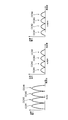
- FIG. 2 is a diagram illustrating the component carrier according to the first embodiment.
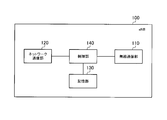
- FIG. 3 is a diagram illustrating the base station eNB 100 according to the first embodiment.
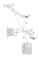
- FIG. 4 is a diagram illustrating a communication control method according to the first embodiment.
- the base station according to the embodiment is defined in the 3GPP standard, and is detected when an uplink signal transmitted from the wireless terminal existing under the other base station to the other base station is detected. Based on the frequency band of the link signal, a control unit is provided for determining a frequency band to be allocated to the wireless terminals existing under the base station. At least in the other base station, the frequency band of the downlink signal is associated with the frequency band of the uplink signal.
- the control unit determines the frequency band to be allocated to the radio terminal existing under the base station based on the frequency band of the uplink signal transmitted from the radio terminal existing under the other base station. Therefore, interference from other base stations and interference to other base stations can be suppressed.
- the frequency band to be allocated to the radio terminals existing under the base station may be the frequency band of the uplink signal or the frequency band of the downlink signal.
- the frequency band is a component carrier defined in the 3GPP standard, for example.
- the component carrier is a frequency band used in one cell, for example.
- FIG. 1 is a diagram showing a mobile communication system 1 according to the first embodiment.
- the mobile communication system 1 is configured based on LTE Advanced (3GPP Release 10 or later).
- the mobile communication system 1 has an E-UTRAN 10 (Evolved UMTS Terrestrial Radio Access Network) which is a radio access network.
- the E-UTRAN 10 is configured as a heterogeneous network, and is configured by a plurality of types of base stations having different transmission powers (that is, service area ranges).
- the E-UTRAN 10 includes a macro base station MeNB that forms a large cell (macro cell), and two femto base stations HeNB (femto base station HeNB # 1) that form a small cell (femto cell). Femto base station HeNB # 2).
- the femto base station HeNB # 1 and the femto base station HeNB # 2 are, for example, within the service area range of the macro base station MeNB and are arranged in a high traffic zone (so-called hot zone).
- positioned in the service area range of macro base station MeNB is not restricted to two, One may be sufficient, and three or more may be sufficient. Note that there may be a situation where the femto base station HeNB is not arranged within the service area range of the macro base station MeNB.
- the service area range of the macro base station MeNB is covered by one or more cells formed by the macro base station MeNB.
- the service area range of the femto base station HeNB # 1 is covered by one or more cells formed by the femto base station HeNB # 1
- the service area range of the femto base station HeNB # 2 is the femto base station HeNB # 2 Covered by one or more cells.
- a cell is the smallest unit of a wireless communication area.
- the cell is provided in each base station, and may be considered as a function of performing radio communication with the radio terminal UE.
- the carrier aggregation technique is a technique for performing wireless communication using a plurality of component carriers collectively.
- the component carrier is a frequency band used in one cell, for example.
- Macro base station MeNB, femto base station HeNB # 1, and femto base station HeNB # 2 perform radio communication with one or a plurality of radio terminals UE. Note that there may be a situation in which the macro base station MeNB, the femto base station HeNB # 1, and the femto base station HeNB # 2 do not perform radio communication with the radio terminal UE.
- the radio terminal UE that performs radio communication with the base station may be referred to as being under the control of the base station.
- a radio terminal UE that supports carrier aggregation technology can use a plurality of component carriers together for radio communication.
- an X2 interface for connecting a plurality of base stations to each other is set.
- an X2 interface is set between the macro base station MeNB and the femto base station HeNB # 1
- an X2 interface is set between the macro base station MeNB and the femto base station HeNB # 2.
- an X2 interface is set between the femto base station HeNB # 1 and the femto base station HeNB # 2.
- the X2 interface may not be set between the macro base station MeNB and the femto base station HeNB.
- the mobile communication system 1 includes a mobility management device MME / gateway device S-GW and a maintenance monitoring device OAM.
- the mobility management device MME is configured to perform various types of mobility control for the radio terminal UE.
- the gateway device S-GW is configured to perform transfer control of user data transmitted and received by the radio terminal UE.
- the maintenance monitoring device OAM is configured to perform maintenance and monitoring of the E-UTRAN 10. Between each base station and EPC (Evolved Packet Core), an S1 interface that connects each base station and EPC is set.
- the EPC is provided with a mobility management device MME, a gateway device S-GW, a maintenance monitoring device OAM, and the like.
- FIG. 2 is a diagram illustrating the component carrier according to the first embodiment.
- each base station performs wireless communication using a plurality of component carriers.
- a case where each base station performs wireless communication using four component carriers is illustrated.
- the number of component carriers used by each base station is not limited to four.
- a case where a plurality of component carriers are continuous in the frequency axis direction is illustrated.
- a plurality of component carriers may be dispersed in the frequency axis direction.
- the plurality of component carriers may be dispersed in the 800 MHz band and the 1.5 GHz band.
- each of the macro base station MeNB, the femto base station HeNB # 1, and the femto base station HeNB # 2 can use four component carriers (CC # 1 to CC # 4).
- Each component carrier is, for example, a frequency band used in one cell of LTE.
- Each component carrier is configured by a plurality of resource blocks (RB) provided along the frequency axis direction.
- the resource block is a unit of radio resources that can be allocated to the radio terminal UE.
- the component carrier of the downlink signal is illustrated.
- the transmission power of the femto base station HeNB # 1 and the femto base station HeNB # 2 is smaller than the transmission power of the macro base station MeNB.
- the uplink signal component carrier is the same as the downlink signal component carrier shown in FIG. In the first embodiment, the component carrier of the downlink signal is associated with the component carrier of the uplink signal.
- FIG. 3 is a block diagram showing the base station eNB 100 according to the first embodiment.
- the base station eNB100 may be a femto base station HeNB or a macro base station MeNB.
- the base station eNB 100 includes a radio communication unit 110, a network communication unit 120, a storage unit 130, and a control unit 140.
- the radio communication unit 110 performs radio communication with the radio terminal UE. Specifically, when the carrier aggregation technology is used, the wireless communication unit 110 performs wireless communication using a plurality of component carriers simultaneously.
- the wireless communication unit 110 includes, for example, a radio frequency (RF) circuit, a baseband (BB) circuit, a modulation / coding circuit, and the like.
- the wireless communication unit 110 receives an uplink signal via an antenna (not shown).
- the wireless communication unit 110 transmits a downlink signal via an antenna (not shown).
- the network communication unit 120 communicates with other network devices. For example, the network communication unit 120 performs inter-base station communication with other base stations via the X2 interface. Alternatively, the network communication unit 120 communicates with the EPC via the S1 interface.
- the storage unit 130 stores information used for controlling the base station eNB100.
- the storage unit 130 stores identification information (base station ID) for identifying the base station eNB100, identification information (for example, cell ID) for identifying a cell included in the base station eNB100, and the like.
- the storage unit 130 associates a component carrier (frequency band) of a downlink signal used in another base station with a component carrier (frequency band) of an uplink signal used in another base station (DL).
- DL component carrier
- / UL CC correspondence table information indicating the usage status of the component carrier of the uplink signal and the component carrier of the downlink signal (CC usage table) in the association
- DL / UL CC correspondence table See Figure 4 for an example of "CC usage table”
- association between the component carrier of the downlink signal and the component carrier of the uplink signal may be determined in advance.
- information which shows matching with the component carrier of a downlink signal and the component carrier of an uplink signal may be acquired from another base station via X2 interface.
- the control unit 140 controls the configuration provided in the base station eNB100. For example, the control unit 140 allocates a component carrier to the radio terminal UE existing under the base station eNB100. In addition, the control part 140 allocates a some component carrier to the radio
- the control unit 140 detects the component carrier of the uplink signal transmitted from the radio terminal UE existing under the other base station to the other base station. Based on the detected component carrier of the uplink signal, the control unit 140 determines a component carrier to be allocated to the radio terminal UE existing under the base station eNB 100 (hereinafter, allocated component carrier). The control unit 140 allocates the determined allocation component carrier to the radio terminal UE, and performs radio communication with the radio terminal UE using the allocation component carrier.
- allocated component carrier a component carrier to be allocated to the radio terminal UE existing under the base station eNB 100
- control unit 140 specifies the component carrier of the downlink signal associated with the component carrier of the detected uplink signal, using the DL / UL CC correspondence table stored in the storage unit 130.
- the control unit 140 determines the component carrier of the detected uplink signal and the component carrier of the downlink signal associated with the component carrier of the detected uplink signal specified by the DL / UL CC coreresponse table. The indicated information is stored in the CC usage table. Each time the control unit 140 detects the component carrier of the uplink signal transmitted from the radio terminal UE existing under the control of another base station to the other base station, the control unit 140 executes the storage process to the CC usage table, Update the usage table.
- control unit 140 stores information indicating “used” in association with the component carrier corresponding to the component carrier used by the radio terminal UE under the control of another base station.
- Information indicating “free” is stored in association with the component carrier.
- the control unit 140 uses the CC usage table to exclude the detected uplink signal component carrier (for example, CC # U1 and CC # U2 of “CC usage table” shown in FIG. 4), and the uplink signal. Assigned component carriers (for example, CC # U3 and CC # U4 of “CC usage table” shown in FIG. 4) are determined. Alternatively, the control unit 140 may detect the component carrier of the downlink signal associated with the detected component carrier of the uplink signal (for example, CC # U1 and CC # U2 of “CC usage table” illustrated in FIG. 4) 4 except for CC # D1 and CC # D2 of “CC usage table” shown in FIG. 4 (for example, CC # D3 and CC # of “CC usage table” shown in FIG. 4). D4) is determined. That is, the control unit 140 determines the allocation component carrier by excluding the component carrier used by the radio terminal UE existing under the control of another base station.
- Assigned component carriers for example, CC # U3 and CC # U4 of “CC
- the other base station is preferably a base station having a service area range that overlaps the service area range of the base station eNB100.
- the other base station is preferably a base station having a service area range adjacent to the service area range of the base station eNB100.
- 1st Embodiment is applicable also to the case where the femto base station HeNB is arbitrarily installed by the user.
- the base station eNB100 is the femto base station HeNB # 1
- the other base station is the femto base station HeNB # 2.
- the other base station may be the macro base station MeNB.
- FIG. 4 is a diagram illustrating a communication control method according to the first embodiment.
- FIG. 4 illustrates a case where the base station eNB100 is the femto base station HeNB # 1 and the other base station is the femto base station HeNB # 2.
- the femto base station HeNB # 2 performs radio communication with the radio terminal UE # 2.
- the femto base station HeNB # 1 allocates a component carrier used by the radio terminal UE # 1 will be described.
- the femto base station HeNB # 1 determines the component carrier (frequency band) of the downlink signal used in the femto base station HeNB # 2 and the uplink signal used in the femto base station HeNB # 2.
- Information DL / UL CC correspondence table
- the association between the component carrier of the downlink signal and the component carrier of the uplink signal may be determined in advance. Or the information which shows matching with the component carrier of a downlink signal and the component carrier of an uplink signal may be acquired from femto base station HeNB # 2 via X2 interface.
- femto base station HeNB # 1 detects the component carrier of the uplink signal transmitted from radio
- the femto base station HeNB # 1 specifies the component carrier of the downlink signal transmitted from the femto base station HeNB # 2 to the radio terminal UE # 2 based on the detected component carrier of the uplink signal. . That is, femto base station HeNB # 1 specifies the component carrier of the downlink signal matched with the component carrier of the detected uplink signal using the information memorize
- the femto base station HeNB # 1 determines a component carrier to be allocated to the radio terminal UE # 1 (hereinafter, allocated component carrier), allocates the determined allocated component carrier to the radio terminal UE, and allocates the allocated component carrier. Is used to perform radio communication with the radio terminal UE # 1.
- the femto base station HeNB # 1 excludes the detected component carrier of the uplink signal and determines an uplink signal allocation component carrier. Or femto base station HeNB # 1 excludes the component carrier of the downlink signal matched with the component carrier of the detected uplink signal, and determines the allocation component carrier of a downlink signal. That is, the femto base station HeNB # 1 determines the allocation component carrier by excluding the component carrier used by the radio terminal UE # 2.
- base station eNB100 allocates to the radio
- a component carrier hereinafter, assigned component carrier
- the base station eNB 100 determines an uplink signal allocation component carrier by excluding the component carrier of the uplink signal transmitted from the radio terminal UE existing under the control of another base station. As a result, interference from the radio terminal UE existing under the base station eNB100 to another base station is reduced. Furthermore, interference with the base station eNB100 from the radio terminal UE existing under the control of another base station is also reduced.
- the base station eNB100 excludes the downlink signal component carrier associated with the uplink signal component carrier transmitted from the radio terminal UE existing under the control of another base station, and assigns a downlink signal allocation component. Determine your career. Thereby, interference from the other base station to the radio terminal UE existing under the base station eNB100 is reduced. Furthermore, interference from the base station eNB100 to the radio terminal UE that is under the control of another base station is also reduced.
- the base station eNB 100 does not need to detect a component carrier of a downlink signal transmitted from another base station. Therefore, even in an FDD (Frequency division duplex) communication system, it is possible to suppress interference without requiring a configuration (new configuration) for detecting a component carrier of a downlink signal.
- FDD Frequency division duplex
- the function of detecting a component carrier of an uplink signal is a function that a conventional base station has.
- the base station eNB 100 may detect the component carrier of the uplink signal transmitted from the radio terminal UE existing under the control of another base station when the power is turned on. .
- base station eNB100 may detect the component carrier of the uplink signal transmitted from the radio
- the base station eNB100 is the femto base station HeNB # 1 and the other base station is the femto base station HeNB # 2 is mainly exemplified.
- the embodiment is not limited to this.
- the base station eNB100 may be the macro base station MeNB, and the other base station may be the macro base station MeNB.
- the base station eNB100 may be a femto base station HeNB (or macro base station MeNB), and the other base station may be a macro base station MeNB (or femto base station HeNB).
- the femto base station HeNB may be read as a pico base station PeNB installed by a communication carrier.
- the base station eNB100 may be a femto base station HeNB (or pico base station PeNB), and the other base station may be a pico base station PeNB (or femto base station HeNB).
- the component carrier of the downlink signal is associated with the component carrier of the uplink signal.
- the component carrier of the downlink signal only needs to be associated with the component carrier of the uplink signal at least in other base stations.
- the maintenance monitoring apparatus OAM may designate at least another base station associating the downlink signal component carrier with the uplink signal component carrier.
- the base station eNB100 acquires information indicating the association between the component carrier of the downlink signal and the component carrier of the uplink signal from the maintenance monitoring apparatus OAM via the S1 interface. That is, the base station eNB100 acquires information indicating the association between the component carrier of the downlink signal and the component carrier of the uplink signal from the upper network device via the S1 interface.
- the component carrier of the downlink signal is associated with the component carrier of the uplink signal in a state where the number of component carriers of the downlink signal is different from the number of component carriers of the uplink signal. May be.
- the base station eNB100 determines the allocation component carrier by excluding the component carrier used by the radio terminal UE existing under the control of another base station.
- the embodiment is not limited to this.
- the base station eNB100 (control unit 140) subordinates the component carrier (for example, CC # U1 and CC # U2 of “CC usage table” shown in FIG. 4) of the detected uplink signal to the base station eNB100.
- the uplink signal is transmitted so that the transmission power of the uplink signal transmitted using the component carrier of the detected uplink signal is lower than a predetermined value.
- the transmission power is controlled (this control is hereinafter referred to as “uplink signal transmission power control”).
- the base station eNB100 (control unit 140) controls uplink signal transmission power using closed loop transmission power control using a TPC bit or the like.
- the base station eNB100 may detect the downlink signal associated with the component carrier of the detected uplink signal (for example, CC # U1 and CC # U2 of “CC usage table” illustrated in FIG. 4). Detected in the case of determining the component carrier (eg, CC # D1 and CC # D2 of “CC usage table” shown in FIG. 4) to be allocated to the radio terminal UE existing under the base station eNB100 The transmission power of the downlink signal is controlled so that the transmission power of the downlink signal transmitted using the component carrier of the downlink signal associated with the component carrier of the uplink signal is lower than a predetermined value (this control is performed). , “Downlink” Referred to as No. transmission power control ").
- control unit 140 determines the component carrier used by the radio terminal UE existing under the other base station as the component carrier to be allocated to the radio terminal UE existing under the base station eNB100.
- the transmission power of the signal transmitted using the component carrier used by the radio terminal UE existing under the control of another base station is reduced.
- the predetermined value is, for example, a transmission power value of a signal transmitted using a component carrier that is not used by a radio terminal UE existing under another base station.
- the predetermined value may be a predetermined value.
- the base station eNB100 when the base station eNB100 (control unit 140) detects an uplink signal transmitted from the radio terminal UE existing under the control of another base station to the other base station, the transmission power of the uplink signal It is preferable to execute the control and the transmission power control of the downlink signal, but based on the transmission power of the component carrier in another base station, the transmission power control of the uplink signal and the transmission power control of the downlink signal It is good also as not performing. That is, the base station eNB100 (control unit 140) can also assign a component carrier used by the radio terminal UE existing under the control of another base station.
- a base station and a communication control method capable of selecting an appropriate combination of component channels in a mobile communication system that supports a carrier aggregation technique defined by the 3GPP standard.
Landscapes
- Engineering & Computer Science (AREA)
- Computer Networks & Wireless Communication (AREA)
- Signal Processing (AREA)
- Quality & Reliability (AREA)
- Mobile Radio Communication Systems (AREA)
Abstract
Description
実施形態に係る基地局は、3GPP規格で規定されており、他の基地局の配下に存在する無線端末から前記他の基地局に送信されるアップリンク信号を検出した場合に、検出されたアップリンク信号の周波数帯域に基づいて、前記基地局の配下に存在する無線端末に割当てるべき周波数帯域を決定する制御部を備える。少なくとも前記他の基地局において、ダウンリンク信号の周波数帯域は、前記アップリンク信号の周波数帯域と対応付けられている。
(移動通信システム)
以下において、第1実施形態に係る移動通信システムについて説明する。図1は、第1実施形態に係る移動通信システム1を示す図である。第1実施形態では、移動通信システム1は、LTE Advanced(3GPPリリース10以降)に基づいて構成される。
以下において、第1実施形態に係るコンポーネントキャリアについて説明する。図2は、第1実施形態に係るコンポーネントキャリアを示す図である。
以下において、第1実施形態に係る基地局について説明する。図3は、第1実施形態に係る基地局eNB100を示すブロック図である。基地局eNB100は、フェムト基地局HeNBであってもよく、マクロ基地局MeNBであってもよい。
以下において、第1実施形態に係る通信制御方法について説明する。図4は、第1実施形態に係る通信制御方法を示す図である。図4では、基地局eNB100がフェムト基地局HeNB#1であり、他の基地局がフェムト基地局HeNB#2であるケースについて例示する。
第1実施形態では、基地局eNB100は、他の基地局の配下に存在する無線端末UEから送信されるアップリンク信号のコンポーネントキャリアに基づいて、基地局eNB100の配下に存在する無線端末UEに割当てるべきコンポーネントキャリア(以下、割当てコンポーネントキャリア)を決定する。従って、他の基地局からの干渉、他の基地局に対する干渉を抑制することができる。
本発明は上述した実施形態によって説明したが、この開示の一部をなす論述及び図面は、この発明を限定するものであると理解すべきではない。この開示から当業者には様々な代替実施形態、実施例及び運用技術が明らかとなろう。
Claims (7)
- 3GPP規格で規定される基地局であって、
他の基地局の配下に存在する無線端末から前記他の基地局に送信されるアップリンク信号を検出した場合に、検出されたアップリンク信号の周波数帯域に基づいて、前記基地局の配下に存在する無線端末に割当てるべき周波数帯域を決定する制御部を備えており、
少なくとも前記他の基地局において、ダウンリンク信号の周波数帯域は、前記アップリンク信号の周波数帯域と対応付けられていることを特徴とする基地局。 - 前記ダウンリンク信号と前記アップリンク信号との対応付けは、予め定められていることを特徴とする請求項1に記載の基地局。
- 前記ダウンリンク信号と前記アップリンク信号との対応付けを示す情報を前記他の基地局又は上位ネットワーク装置から取得する取得部をさらに備えることを特徴とする請求項1に記載の基地局。
- 前記制御部は、前記他の基地局の配下に存在する無線端末が用いる周波数帯域を除外して、前記基地局の配下に存在する無線端末に割当てるべき周波数帯域を決定することを特徴とする請求項1に記載の基地局。
- 前記制御部は、前記他の基地局の配下に存在する無線端末が用いる周波数帯域を前記基地局の配下に存在する無線端末に割当てるべき周波数帯域として決定する場合に、前記他の基地局の配下に存在する無線端末が用いる周波数帯域を用いて送信する信号の送信電力を低減することを特徴とする請求項1に記載の基地局。
- 前記周波数帯域は、3GPP規格で規定されるコンポーネントキャリアであることを特徴とする請求項1に記載の基地局。
- 3GPP規格で規定される基地局における通信制御方法であって、
他の基地局の配下に存在する無線端末から前記他の基地局に送信されるアップリンク信号を検出した場合に、検出されたアップリンク信号の周波数帯域に基づいて、前記基地局の配下に存在する無線端末に割当てるべき周波数帯域を決定するステップを有しており、
少なくとも前記他の基地局において、ダウンリンク信号の周波数帯域は、前記アップリンク信号の周波数帯域と対応付けられていることを特徴とする通信制御方法。
Priority Applications (3)
| Application Number | Priority Date | Filing Date | Title |
|---|---|---|---|
| JP2013511851A JPWO2012147198A1 (ja) | 2011-04-28 | 2011-04-28 | 基地局及び通信制御方法 |
| PCT/JP2011/060423 WO2012147198A1 (ja) | 2011-04-28 | 2011-04-28 | 基地局及び通信制御方法 |
| US14/113,796 US20140051453A1 (en) | 2011-04-28 | 2011-04-28 | Base station and communication control method |
Applications Claiming Priority (1)
| Application Number | Priority Date | Filing Date | Title |
|---|---|---|---|
| PCT/JP2011/060423 WO2012147198A1 (ja) | 2011-04-28 | 2011-04-28 | 基地局及び通信制御方法 |
Publications (1)
| Publication Number | Publication Date |
|---|---|
| WO2012147198A1 true WO2012147198A1 (ja) | 2012-11-01 |
Family
ID=47071738
Family Applications (1)
| Application Number | Title | Priority Date | Filing Date |
|---|---|---|---|
| PCT/JP2011/060423 Ceased WO2012147198A1 (ja) | 2011-04-28 | 2011-04-28 | 基地局及び通信制御方法 |
Country Status (3)
| Country | Link |
|---|---|
| US (1) | US20140051453A1 (ja) |
| JP (1) | JPWO2012147198A1 (ja) |
| WO (1) | WO2012147198A1 (ja) |
Cited By (2)
| Publication number | Priority date | Publication date | Assignee | Title |
|---|---|---|---|---|
| WO2013084694A1 (ja) * | 2011-12-07 | 2013-06-13 | ソニー株式会社 | 無線基地局、無線基地局の通信制御方法及びコンピュータプログラム |
| JP2014209688A (ja) * | 2013-04-16 | 2014-11-06 | 日本電信電話株式会社 | 無線通信システム、無線通信方法、無線基地局装置および遠隔制御装置 |
Citations (2)
| Publication number | Priority date | Publication date | Assignee | Title |
|---|---|---|---|---|
| WO2010084688A1 (ja) * | 2009-01-20 | 2010-07-29 | シャープ株式会社 | 移動局装置、基地局装置、無線リンク同期判定方法 |
| JP2010178237A (ja) * | 2009-02-02 | 2010-08-12 | Sharp Corp | 通信システム及び基地局装置、端末装置、および基地局装置、端末装置に実行させるプログラム |
Family Cites Families (2)
| Publication number | Priority date | Publication date | Assignee | Title |
|---|---|---|---|---|
| KR100765892B1 (ko) * | 2006-08-30 | 2007-10-10 | 주식회사 팬택 | 이동통신 시스템의 셀간 간섭을 제어하는 방법 |
| US8442541B2 (en) * | 2010-03-29 | 2013-05-14 | Ntt Docomo, Inc. | System and method for inter-cell interference avoidance in co-channel networks |
-
2011
- 2011-04-28 WO PCT/JP2011/060423 patent/WO2012147198A1/ja not_active Ceased
- 2011-04-28 JP JP2013511851A patent/JPWO2012147198A1/ja active Pending
- 2011-04-28 US US14/113,796 patent/US20140051453A1/en not_active Abandoned
Patent Citations (2)
| Publication number | Priority date | Publication date | Assignee | Title |
|---|---|---|---|---|
| WO2010084688A1 (ja) * | 2009-01-20 | 2010-07-29 | シャープ株式会社 | 移動局装置、基地局装置、無線リンク同期判定方法 |
| JP2010178237A (ja) * | 2009-02-02 | 2010-08-12 | Sharp Corp | 通信システム及び基地局装置、端末装置、および基地局装置、端末装置に実行させるプログラム |
Non-Patent Citations (1)
| Title |
|---|
| QUALCOMM EUROPE: "Carrier Aggregation in Heterogeneous Networks", 3GPP TSG RAN WG1 #57 R1-092062, 4 May 2009 (2009-05-04), Retrieved from the Internet <URL:http://www.3gpp.org/ftp/tsg_ran/wg1_r11/TSGR157/Docs/R1-092062.zip> [retrieved on 20110603] * |
Cited By (3)
| Publication number | Priority date | Publication date | Assignee | Title |
|---|---|---|---|---|
| WO2013084694A1 (ja) * | 2011-12-07 | 2013-06-13 | ソニー株式会社 | 無線基地局、無線基地局の通信制御方法及びコンピュータプログラム |
| US9332562B2 (en) | 2011-12-07 | 2016-05-03 | Sony Corporation | Radio base station, communication control method of radio base station and computer program |
| JP2014209688A (ja) * | 2013-04-16 | 2014-11-06 | 日本電信電話株式会社 | 無線通信システム、無線通信方法、無線基地局装置および遠隔制御装置 |
Also Published As
| Publication number | Publication date |
|---|---|
| US20140051453A1 (en) | 2014-02-20 |
| JPWO2012147198A1 (ja) | 2014-07-28 |
Similar Documents
| Publication | Publication Date | Title |
|---|---|---|
| JP6932806B2 (ja) | 狭帯域デバイスにおけるdcサブキャリア処理 | |
| US9560560B2 (en) | User equipment and methods for handover using measurement reporting based on multiple events | |
| US9231723B2 (en) | Coordinated dynamic point selection (DPS) with cell range expansion in a coordinated multipoint (CoMP) system | |
| CN101420746B (zh) | 一种小区间干扰协调方法及其干扰协调信息传递方式 | |
| US10051661B2 (en) | Method and apparatus for communicating using unlicensed bands in mobile communication system | |
| TWI575972B (zh) | 為了改進涵蓋範圍平衡性的用於跨小區載波聚合之系統及方法 | |
| KR20180013862A (ko) | 5g 및 lte 시스템 및 장치에서의 단절없는 이동 | |
| US20150350928A1 (en) | Method for interference cancellation with low-power subframes in heterogeneous networks | |
| JP6045808B2 (ja) | ユーザ端末、無線基地局、及び無線通信方法 | |
| KR20170093842A (ko) | 비허가 무선 주파수 스펙트럼 대역에서의 송신들을 관리하는 기법들 | |
| US9642135B2 (en) | Method and apparatus for management of protected resource in a heterogeneous network | |
| KR20150121228A (ko) | Mtc 디바이스 연관 방식 | |
| JP2016530771A (ja) | 上下リンク構成の指示方法、特定方法並びに基地局、端末 | |
| US20160192262A1 (en) | Communications system radio coverage reconfiguration based on available capacity of a compensation cell | |
| JP5767738B2 (ja) | 通信制御方法、基地局、及び無線端末 | |
| JP6092521B2 (ja) | 通信システム、移動端末装置、ローカルエリア基地局装置及び通信方法 | |
| US12362894B2 (en) | Carrier specific scaling factor for deactivated PSCell | |
| JP2015070300A (ja) | 通信制御方法、基地局、及びユーザ端末 | |
| WO2012147198A1 (ja) | 基地局及び通信制御方法 | |
| US20170013622A1 (en) | Carrier swapping for lte-u (lte-unlicensed spectrum) method and apparatus | |
| JP7161017B2 (ja) | 端末、無線通信方法、基地局装置及び無線通信システム | |
| McMenamy et al. | RRH and small cells—The implications for spectrum sharing | |
| Shi et al. | A flexible backhaul architecture for small cell networks | |
| JP2017099023A (ja) | 通信システム、移動端末装置、ローカルエリア基地局装置及び通信方法 | |
| CN103716842A (zh) | 一种微蜂窝与宏蜂窝组网中小区id的使用方法 |
Legal Events
| Date | Code | Title | Description |
|---|---|---|---|
| 121 | Ep: the epo has been informed by wipo that ep was designated in this application |
Ref document number: 11864398 Country of ref document: EP Kind code of ref document: A1 |
|
| ENP | Entry into the national phase |
Ref document number: 2013511851 Country of ref document: JP Kind code of ref document: A |
|
| WWE | Wipo information: entry into national phase |
Ref document number: 14113796 Country of ref document: US |
|
| NENP | Non-entry into the national phase |
Ref country code: DE |
|
| 122 | Ep: pct application non-entry in european phase |
Ref document number: 11864398 Country of ref document: EP Kind code of ref document: A1 |