WO2012147196A1 - Sound signal processing device and sound signal processing program - Google Patents
Sound signal processing device and sound signal processing program Download PDFInfo
- Publication number
- WO2012147196A1 WO2012147196A1 PCT/JP2011/060416 JP2011060416W WO2012147196A1 WO 2012147196 A1 WO2012147196 A1 WO 2012147196A1 JP 2011060416 W JP2011060416 W JP 2011060416W WO 2012147196 A1 WO2012147196 A1 WO 2012147196A1
- Authority
- WO
- WIPO (PCT)
- Prior art keywords
- signal
- channel signal
- surround
- distance
- sound
- Prior art date
Links
Images


Classifications
-
- H—ELECTRICITY
- H04—ELECTRIC COMMUNICATION TECHNIQUE
- H04S—STEREOPHONIC SYSTEMS
- H04S3/00—Systems employing more than two channels, e.g. quadraphonic
- H04S3/002—Non-adaptive circuits, e.g. manually adjustable or static, for enhancing the sound image or the spatial distribution
-
- H—ELECTRICITY
- H04—ELECTRIC COMMUNICATION TECHNIQUE
- H04S—STEREOPHONIC SYSTEMS
- H04S7/00—Indicating arrangements; Control arrangements, e.g. balance control
- H04S7/30—Control circuits for electronic adaptation of the sound field
- H04S7/301—Automatic calibration of stereophonic sound system, e.g. with test microphone
Definitions
- a display device including a monitor, left and right front speakers and left and right surround speakers, and the above-described audio signal processing device can be provided.
Abstract
A sound signal processing device receives an input signal including a front channel signal and a surround channel signal and generates a delayed surround channel signal by delaying the surround channel signal by a given delay time. Then, the sound signal processing device adds the delayed surround channel signal to the front channel signal and outputs the added signal. Because the surround signal is output from a front speaker with a given delay, by setting an appropriate delay time depending on the size, etc., of a room, a listener can feel the depth and width of a room in accordance with the delay time.
Description
本発明は、マルチチャンネル音声信号の処理に関する。
The present invention relates to processing of multi-channel audio signals.
映像ソースとともに再生される音声信号として、5.1チャンネルなどのマルチチャンネル音声信号を用いて立体感のある音声再生を行う手法が知られている。
There is known a technique for reproducing a three-dimensional sound using a multi-channel audio signal such as 5.1 channel as an audio signal reproduced together with a video source.
例えば、特許文献1は、マルチチャンネルシステムにおいて、音源の後ろの壁からの反射音及び横壁からの反射音に相当する音を作り出すことにより、スピーカより遠い方向への奥行き感を増強し、映画館のようなスクリーン方向への音の広がりを実現することを提案している。
For example, in Patent Document 1, in a multi-channel system, a sound corresponding to a reflected sound from a wall behind a sound source and a reflected sound from a side wall is created, thereby enhancing a sense of depth in a direction farther than a speaker. It has been proposed to realize the spread of sound in the screen direction.
特許文献2は、音声信号に対する頭部伝達関数処理によりアレイスピーカ装置の後ろ側に仮想点音源を定位させ、アレイスピーカ装置の設置環境にかかわらず聴取者にサラウンドサウンドを提供する手法を記載している。
Patent Document 2 describes a method of providing a surround sound to a listener regardless of the installation environment of the array speaker device by locating a virtual point sound source behind the array speaker device by a head-related transfer function process for an audio signal. Yes.
特許文献3は、直接音に加えて、初期反射音及び残響音を付加することにより、臨場感の高い音場を作ることを提案している。
Patent Document 3 proposes to create a highly realistic sound field by adding initial reflected sound and reverberation sound in addition to direct sound.
しかし、上記のいずれの文献においても、前方の音源の奥行方向において具体的にどの程度の遅延を行うべきかについては明確ではない。例えば特許文献1は、「遅延時間及びそれらの信号を原音に対して混ぜる比率を適当に決めることによりセンタ方向への奥行き感を創出することができる」旨を記載するに過ぎない(特許文献1、段落0014参照)。また、従来技術のように単に初期反射の付加だけでは仮想音源(仮想スピーカ、仮想壁)までの距離感が不明確であった。
However, in any of the above documents, it is not clear how much delay should be performed in the depth direction of the sound source ahead. For example, Patent Document 1 merely describes that “a sense of depth toward the center can be created by appropriately determining the delay time and the ratio of mixing those signals with the original sound” (Patent Document 1). , Paragraph 0014). In addition, as in the prior art, the sense of distance to the virtual sound source (virtual speaker, virtual wall) is unclear simply by adding initial reflection.
本発明が解決しようとする課題としては、上記のものが例として挙げられる。本発明は、部屋の大きさに合わせて適切な信号の遅延を行うことにより、過不足、違和感の無い、リアルな仮想音場空間を作り出すこと、及び、壁の向こう側の仮想音場空間と壁より手前の実音場空間との音場のつながりを向上することを目的とする。
The above are examples of problems to be solved by the present invention. The present invention creates a realistic virtual sound field space that is free of overs and shorts and a sense of incongruity by performing an appropriate signal delay according to the size of the room, and a virtual sound field space on the other side of the wall The purpose is to improve the connection of the sound field with the real sound field space in front of the wall.
請求項1に記載の発明は、音声信号処理装置であって、フロントチャンネル信号及びサラウンドチャンネル信号を含む入力信号を受け取る入力部と、サラウンドチャンネル信号を所定の遅延時間遅延して遅延サラウンドチャンネル信号を生成する遅延手段と、フロントチャンネル信号に対して、初期反射処理及び/又はリバーブ処理により仮想音場空間を作り出す処理を行う処理手段と、前記遅延サラウンドチャンネル信号を、前記処理手段により処理されたフロントチャンネル信号に加算する加算手段と、前記加算手段により出力されたフロントチャンネル信号、及び、サラウンドチャンネル信号を出力する出力手段と、を備えることを特徴とする。
The invention according to claim 1 is an audio signal processing device, an input unit for receiving an input signal including a front channel signal and a surround channel signal, and a delay surround channel signal obtained by delaying the surround channel signal by a predetermined delay time. A delay unit for generating; a processing unit for generating a virtual sound field space by initial reflection processing and / or reverb processing for the front channel signal; and a front processed by the processing unit for processing the delayed surround channel signal. An addition means for adding to the channel signal; and an output means for outputting the front channel signal and the surround channel signal output by the addition means.
請求項10に記載の発明は、コンピュータを備える装置により実行される音声信号処理プログラムであって、フロントチャンネル信号及びサラウンドチャンネル信号を含む入力信号を受け取る入力手段、サラウンドチャンネル信号を所定の遅延時間遅延して遅延サラウンドチャンネル信号を生成する遅延手段、フロントチャンネル信号に対して、初期反射処理及び/又はリバーブ処理により仮想音場空間を作り出す処理を行う処理手段、前記遅延サラウンドチャンネル信号を、前記処理手段により処理されたフロントチャンネル信号に加算する加算手段、前記加算手段により出力されたフロントチャンネル信号、及び、サラウンドチャンネル信号を出力する出力手段、として前記コンピュータを機能させることを特徴とする。
According to a tenth aspect of the present invention, there is provided an audio signal processing program executed by an apparatus including a computer, wherein the input means receives an input signal including a front channel signal and a surround channel signal, and the surround channel signal is delayed by a predetermined delay time. Delay means for generating a delayed surround channel signal, processing means for processing the front channel signal to create a virtual sound field space by initial reflection processing and / or reverberation processing, and processing the delay surround channel signal. The computer is caused to function as an adding means for adding to the front channel signal processed by the above, an output means for outputting the front channel signal output from the adding means, and a surround channel signal.
本発明の好適な実施形態では、音声信号処理装置は、フロントチャンネル信号及びサラウンドチャンネル信号を含む入力信号を受け取る入力部と、サラウンドチャンネル信号を所定の遅延時間遅延して遅延サラウンドチャンネル信号を生成する遅延手段と、フロントチャンネル信号に対して、初期反射処理及び/又はリバーブ処理により仮想音場空間を作り出す処理を行う処理手段と、前記遅延サラウンドチャンネル信号を、前記処理手段により処理されたフロントチャンネル信号に加算する加算手段と、前記加算手段により出力されたフロントチャンネル信号、及び、サラウンドチャンネル信号を出力する出力手段と、を備える。
In a preferred embodiment of the present invention, the audio signal processing device generates an delayed surround channel signal by delaying the surround channel signal by a predetermined delay time and an input unit that receives an input signal including a front channel signal and a surround channel signal. A delay means, a processing means for creating a virtual sound field space by an initial reflection process and / or a reverb process for the front channel signal, and a front channel signal obtained by processing the delayed surround channel signal by the processing means. And an output means for outputting a front channel signal and a surround channel signal output by the adding means.
上記の音声信号処理装置は、フロントチャンネル信号及びサラウンドチャンネル信号を含む入力信号を受け取り、サラウンドチャンネル信号を所定の遅延時間遅延して遅延サラウンドチャンネル信号を生成する。また、フロントチャンネル信号に対して、初期反射処理及び/又はリバーブ処理により仮想音場空間を作り出す処理を行う。そして、遅延サラウンドチャンネル信号を、上記処理後のフロントチャンネル信号に加算し、出力する。サラウンド信号が所定の遅延をもってフロントスピーカからされるので、部屋の大きさなどに応じた適切な遅延時間を設定することにより、視聴者はその遅延時間に応じた部屋の奥行き、広がりを感じることができる。
The above audio signal processing apparatus receives an input signal including a front channel signal and a surround channel signal, and generates a delayed surround channel signal by delaying the surround channel signal by a predetermined delay time. In addition, processing for creating a virtual sound field space is performed on the front channel signal by initial reflection processing and / or reverberation processing. Then, the delayed surround channel signal is added to the processed front channel signal and output. Since the surround signal is transmitted from the front speaker with a predetermined delay, the viewer may feel the depth and spread of the room according to the delay time by setting an appropriate delay time according to the size of the room. it can.
上記の音声信号処理装置の一態様では、前記表示装置はセンタースピーカを備え、前記加算手段は、前記遅延サラウンドチャンネル信号をセンターチャンネル信号に加算する。この態様では、遅延サラウンド信号がセンタースピーカからも出力されるので、より奥行き感が増強される。
In one aspect of the audio signal processing device, the display device includes a center speaker, and the adding means adds the delayed surround channel signal to the center channel signal. In this aspect, since the delayed surround signal is also output from the center speaker, the sense of depth is further enhanced.
好適な実施例では、上記の音声信号処理装置は、モニタと、左右のフロントスピーカ及び左右のサラウンドスピーカとを備える表示装置に用いられる。
In a preferred embodiment, the audio signal processing device is used in a display device including a monitor, left and right front speakers, and left and right surround speakers.
実験などによる好適な例では、前記所定の遅延時間は、30~40msとされる。他の好適な例では、視聴対象物位置と視聴位置との距離である視聴対象物距離を検出する視聴対象物距離検出手段を備え、前記所定の遅延時間は、前記視聴対象物距離の4~5倍の距離による音波遅延に相当する遅延時間とされる。
In a preferred example based on experiments, the predetermined delay time is 30 to 40 ms. In another preferred example, a viewing object distance detecting unit that detects a viewing object distance that is a distance between the viewing object position and the viewing position is provided, and the predetermined delay time is 4 to 4 of the viewing object distance. The delay time corresponds to the sound wave delay due to the five times distance.
上記の音声信号処理装置の他の一態様は、視聴対象物位置と視聴位置との距離である視聴対象物距離を検出する視聴対象物距離検出手段と、前記視聴対象物距離に基づいて、視聴位置から見てモニタの後方に仮想スピーカを想定し、当該仮想スピーカと視聴位置との距離である仮想スピーカ距離を前記視聴対象物距離の2倍に決定する仮想スピーカ距離決定手段と、を備え、前記遅延手段は、前記仮想スピーカ距離に基づいて前記所定の遅延時間を決定する。この態様では、視聴対象物距離に応じて適切な大きさの仮想音場空間が想定され、仮想スピーカ位置が決定されるので、遅延サラウンドチャンネル信号に適切な量の遅延を与えることができる。
Another aspect of the audio signal processing device described above is based on the viewing object distance detection unit that detects a viewing object distance that is a distance between the viewing object position and the viewing position, and based on the viewing object distance. Virtual speaker distance determining means that assumes a virtual speaker behind the monitor when viewed from the position, and determines a virtual speaker distance that is the distance between the virtual speaker and the viewing position to be twice the viewing object distance; The delay means determines the predetermined delay time based on the virtual speaker distance. In this aspect, a virtual sound field space of an appropriate size is assumed according to the viewing object distance, and the virtual speaker position is determined, so that an appropriate amount of delay can be given to the delayed surround channel signal.
上記の音声信号処理装置の他の一態様では、前記視聴対象物距離検出手段は、前記視聴位置を含む空間にテスト音を出力する放音手段と、前記放音手段により放音されたテスト音を前記視聴位置において集音する集音手段と、前記放音手段により放音されたテスト音に対する、前記集音手段により集音されたテスト音の遅延量に基づいて、前記視聴位置とフロントスピーカとの距離を算出し、当該フロントスピーカの距離に基づいて前記視聴対象物距離を算出する算出手段と、を備える。この態様では、スピーカから出力したテスト信号を集音することにより、フロントスピーカの距離が自動検出され、それに基づいて視聴対象物距離が算出される。よって、視聴対象物距離をユーザが自ら入力する必要がない。
In another aspect of the audio signal processing device, the viewing object distance detecting unit includes a sound emitting unit that outputs a test sound in a space including the viewing position, and a test sound emitted by the sound emitting unit. Sound collecting means for collecting sound at the viewing position, and the viewing position and the front speaker based on a delay amount of the test sound collected by the sound collecting means with respect to the test sound emitted by the sound emitting means. And calculating means for calculating the viewing object distance based on the distance of the front speaker. In this aspect, by collecting the test signal output from the speaker, the distance of the front speaker is automatically detected, and the viewing object distance is calculated based on the distance. Therefore, it is not necessary for the user to input the viewing object distance by himself / herself.
上記の音声信号処理装置の他の一態様は、左右のフロントスピーカから出力される音の音像が実際の左右のフロントスピーカの位置よりも前記モニタの中央よりに定位するように、前記遅延サラウンドチャンネル信号に対して頭部伝達関数処理を行う頭部伝達関数処理手段を備える。これにより、遅延サラウンドチャンネル信号の音像を実際の左右のフロントスピーカの位置よりも中央よりに定位させることができ、よりリアルに奥行き感を創出することができる。
In another aspect of the audio signal processing device, the delay surround channel is configured so that the sound image of the sound output from the left and right front speakers is localized from the center of the monitor rather than the actual position of the left and right front speakers. Head-related transfer function processing means for performing head-related transfer function processing on the signal is provided. As a result, the sound image of the delayed surround channel signal can be localized from the center rather than the actual position of the left and right front speakers, and a sense of depth can be created more realistically.
上記の音声信号処理装置の他の一態様は、左サラウンドチャンネル信号の位相を反転させ、所定量減衰させた信号を右サラウンドチャンネル信号に加算する手段と、右サラウンドチャンネル信号の位相を反転させ、前記所定量減衰させた信号を左サラウンドチャンネル信号に加算する手段と、を備える。これにより、さらに臨場感を増すことができる。
Another aspect of the audio signal processing device described above is a means for inverting the phase of the left surround channel signal, adding a signal attenuated by a predetermined amount to the right surround channel signal, inverting the phase of the right surround channel signal, Means for adding the signal attenuated by the predetermined amount to the left surround channel signal. Thereby, a sense of reality can be further increased.
本発明の他の実施形態では、モニタと、左右のフロントスピーカ及び左右のサラウンドスピーカと、上記の音声信号処理装置と、を備える表示装置を提供することができる。
In another embodiment of the present invention, a display device including a monitor, left and right front speakers and left and right surround speakers, and the above-described audio signal processing device can be provided.
本発明の他の実施形態では、コンピュータを備える装置により実行される音声信号処理プログラムは、フロントチャンネル信号及びサラウンドチャンネル信号を含む入力信号を受け取る入力手段、サラウンドチャンネル信号を所定の遅延時間遅延して遅延サラウンドチャンネル信号を生成する遅延手段、フロントチャンネル信号に対して、初期反射処理及び/又はリバーブ処理により仮想音場空間を作り出す処理を行う処理手段、前記遅延サラウンドチャンネル信号を、前記処理手段により処理されたフロントチャンネル信号に加算する加算手段、前記加算手段より出力されたフロントチャンネル信号、及び、サラウンドチャンネル信号を出力する出力手段、として前記コンピュータを機能させる。このプログラムを表示装置のコンピュータが実行することにより、上記の音声信号処理装置を実現することができる。
In another embodiment of the present invention, an audio signal processing program executed by an apparatus including a computer includes an input means for receiving an input signal including a front channel signal and a surround channel signal, and delaying the surround channel signal by a predetermined delay time. Delay means for generating a delayed surround channel signal, processing means for processing the front channel signal to create a virtual sound field space by initial reflection processing and / or reverberation processing, and processing the delayed surround channel signal by the processing means The computer is caused to function as addition means for adding to the received front channel signal, output means for outputting the front channel signal output from the addition means, and the surround channel signal. When the computer of the display device executes this program, the above audio signal processing device can be realized.
以下、図面を参照して本発明の好適な実施例について説明する。
Hereinafter, preferred embodiments of the present invention will be described with reference to the drawings.
[第1実施例]
(全体構成)
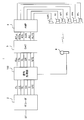
図1は、本発明の音声信号処理装置を適用した音声信号再生装置の構成を示すブロック図である。音声信号再生装置1は、デコーダ2と、本発明に係る音声信号処理装置の実施例である信号処理部100と、D/A変換器3と、アンプ4と、スピーカ5FL、5FR、5C、5SL、5SR及び5LFEと、マイク6とを備える。 [First embodiment]
(overall structure)
FIG. 1 is a block diagram showing the configuration of an audio signal reproduction apparatus to which an audio signal processing apparatus of the present invention is applied. The audiosignal reproduction apparatus 1 includes a decoder 2, a signal processing unit 100 that is an embodiment of the audio signal processing apparatus according to the present invention, a D / A converter 3, an amplifier 4, and speakers 5FL, 5FR, 5C, and 5SL. 5SR and 5LFE, and a microphone 6 are provided.
(全体構成)
図1は、本発明の音声信号処理装置を適用した音声信号再生装置の構成を示すブロック図である。音声信号再生装置1は、デコーダ2と、本発明に係る音声信号処理装置の実施例である信号処理部100と、D/A変換器3と、アンプ4と、スピーカ5FL、5FR、5C、5SL、5SR及び5LFEと、マイク6とを備える。 [First embodiment]
(overall structure)
FIG. 1 is a block diagram showing the configuration of an audio signal reproduction apparatus to which an audio signal processing apparatus of the present invention is applied. The audio
デコーダ2は、信号ソースから圧縮ストリームSTを受け取る。信号ソースとしては、例えばDVD、BD、ハードディスクレコーダなどが挙げられる。これらの記録媒体には映像信号と音声信号とが記録されるが、デコーダ2は映像信号と音声信号とを含む圧縮ストリームを受け取ってもよいし、音声信号のみの圧縮ストリームを受け取ってもよい。
The decoder 2 receives the compressed stream ST from the signal source. Examples of the signal source include a DVD, a BD, and a hard disk recorder. The video signal and the audio signal are recorded on these recording media, but the decoder 2 may receive a compressed stream including the video signal and the audio signal, or may receive a compressed stream of only the audio signal.
デコーダ2は、受け取った圧縮ストリームSTを復号化し、ディジタルの音声信号を生成する。具体的には、デコーダ2は、左フロントチャンネル信号FL、右フロントチャンネル信号FR、左サラウンドチャンネル信号SL、右サラウンドチャンネル信号SR、センターチャンネル信号C及びLFE(Low Frequency Effect)信号LFEを生成し、信号処理部100へ供給する。以下、「チャンネル」を「ch」とも表記する。
The decoder 2 decodes the received compressed stream ST and generates a digital audio signal. Specifically, the decoder 2 generates a left front channel signal FL, a right front channel signal FR, a left surround channel signal SL, a right surround channel signal SR, a center channel signal C, and an LFE (Low Frequency Effect) signal LFE, The signal is supplied to the signal processing unit 100. Hereinafter, “channel” is also expressed as “ch”.
信号処理部100は、入力された信号に基づいて、フロントch信号に対する信号処理を行い、処理後の信号をD/A変換器3へ供給する。具体的には、信号処理部100は、センターch信号C、サラウンドch信号SR及びSL、並びにLFE信号LFEをそのままD/A変換器3へ出力するとともに、信号処理により得られたフロントch信号FLx及びFRxをD/A変換器3へ出力する。なお、この信号処理については後に詳しく説明する。
The signal processing unit 100 performs signal processing on the front ch signal based on the input signal, and supplies the processed signal to the D / A converter 3. Specifically, the signal processing unit 100 outputs the center ch signal C, the surround ch signals SR and SL, and the LFE signal LFE as they are to the D / A converter 3, and the front ch signal FLx obtained by the signal processing. And FRx are output to the D / A converter 3. This signal processing will be described later in detail.
D/A変換器3は、受け取った信号FLx、FRx、SL、SR、C及びLFEをそれぞれD/A変換し、アンプ4へ出力する。アンプ4は各信号を増幅し、各チャンネルのスピーカ5FL、5FR、5C、5SL、5SR及び5LFEへ出力する。
The D / A converter 3 performs D / A conversion on the received signals FLx, FRx, SL, SR, C, and LFE, and outputs them to the amplifier 4. The amplifier 4 amplifies each signal and outputs it to the speakers 5FL, 5FR, 5C, 5SL, 5SR and 5LFE of each channel.
(信号処理)
次に、信号処理部100が実行する信号処理について説明する。本実施例では、ユーザのリスニングルームなどの視聴空間の大きさに合わせて、サラウンドch信号を所定時間遅延した信号(以下、「遅延サラウンドch信号」と呼ぶ。)を生成し、これをフロントch信号に加算してフロントスピーカから再生する。これにより、適度な前方奥行き感を実現する。 (Signal processing)
Next, signal processing performed by thesignal processing unit 100 will be described. In this embodiment, a signal obtained by delaying a surround ch signal for a predetermined time (hereinafter referred to as “delayed surround ch signal”) is generated in accordance with the size of a viewing space such as a user's listening room, and this is generated as a front ch. It is added to the signal and reproduced from the front speaker. Thereby, a moderate forward depth feeling is realized.
次に、信号処理部100が実行する信号処理について説明する。本実施例では、ユーザのリスニングルームなどの視聴空間の大きさに合わせて、サラウンドch信号を所定時間遅延した信号(以下、「遅延サラウンドch信号」と呼ぶ。)を生成し、これをフロントch信号に加算してフロントスピーカから再生する。これにより、適度な前方奥行き感を実現する。 (Signal processing)
Next, signal processing performed by the
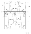
実施例に係る視聴空間の構成例を図2に示す。図示のように、部屋7の1つの壁7wに沿ってTV9が配置され、TV9の内部又は近傍にセンタースピーカ5C、フロントスピーカ5FL及び5FRが配置される。TV9の前方ほぼ中央に視聴位置LPが設定され、視聴者(ユーザ)は視聴位置LPにおいてTV9に表示される映像及び各スピーカから出力される音声を視聴する。視聴位置LPの後方には、サラウンドスピーカ5SL及び5SRが配置される。なお、LFEchのスピーカ5LFEは部屋7内の任意の場所に配置されるので、図示を省略する。
FIG. 2 shows a configuration example of the viewing space according to the embodiment. As illustrated, a TV 9 is disposed along one wall 7w of the room 7, and a center speaker 5C and front speakers 5FL and 5FR are disposed in or near the TV 9. A viewing position LP is set approximately in the center of the TV 9, and the viewer (user) views the video displayed on the TV 9 and the audio output from each speaker at the viewing position LP. Surround speakers 5SL and 5SR are arranged behind the viewing position LP. Note that the LFEch speaker 5LFE is arranged at an arbitrary location in the room 7 and is not shown.
また、本実施例では、視聴位置LPから見て部屋7のTV9の後方に仮想音場空間8を想定し、仮想音場空間8の奥の壁8wに沿って仮想スピーカ5VL及び5VRを想定する。そして、左右のサラウンドch信号SL、SRを所定時間遅延した遅延サラウンド信号SLd、SRdを左右のフロントch信号FL、FRにそれぞれ加算してフロントch信号FLx、FRxを生成し、左右のフロントスピーカ5FL、5FRから出力する。これにより、再生される音声に対して、仮想音場空間8による奥行き感を与えることができる。
Further, in this embodiment, a virtual sound field space 8 is assumed behind the TV 9 in the room 7 when viewed from the viewing position LP, and virtual speakers 5VL and 5VR are assumed along the wall 8w at the back of the virtual sound field space 8. . Then, the left and right surround ch signals SL and SR are delayed by a predetermined time to add the delayed surround signals SLd and SRd to the left and right front ch signals FL and FR, respectively, thereby generating front ch signals FLx and FRx, and left and right front speakers 5FL. Output from 5FR. Thereby, a feeling of depth by the virtual sound field space 8 can be given to the reproduced sound.
まず、仮想音場空間について説明する。仮想音場空間8は、実音場、即ち、実際の部屋7の大きさによって理想の大きさが変わってくる。実音場が小さいのに過剰に大きい仮想音場空間を想定すると違和感が生じるし、逆に実音場が大きいのに仮想音場空間が小さいと奥行き感を創出する効果が不足することになる。TV9又はセンタースピーカ5C(以下、「視聴対象物」と呼ぶ。)と視聴位置LPとの距離(以下、「視聴対象物距離」と呼ぶ。)L1に対して仮想音場空間8の奥行距離L2を変化させて多数の視聴者に対して実験を行ったところ、仮想音場空間8の理想的な奥行距離L2は、視聴位置LPから視聴対象物までの距離L1とほぼ等しいことがわかった。よって、仮想音場空間8の奥行距離L2は、視聴対象物距離L1の0.8~1.2倍程度、好適にはL2=L1となる。よって、好適な例では、視聴位置LPと仮想スピーカ5VL、5VRとの距離(以下「仮想スピーカ距離D」と呼ぶ。)は、視聴対象物距離L1の約2倍となる。
First, the virtual sound field space will be described. The ideal size of the virtual sound field space 8 varies depending on the actual sound field, that is, the actual size of the room 7. If the virtual sound field space is excessively large even though the real sound field is small, a sense of incongruity occurs. Conversely, if the virtual sound field space is small even though the real sound field is large, the effect of creating a sense of depth is insufficient. The depth L2 of the virtual sound field space 8 with respect to the distance L1 between the TV 9 or the center speaker 5C (hereinafter referred to as “viewing object”) and the viewing position LP (hereinafter referred to as “viewing object distance”). As a result of experimenting with a large number of viewers, it was found that the ideal depth distance L2 of the virtual sound field space 8 is substantially equal to the distance L1 from the viewing position LP to the viewing object. Therefore, the depth distance L2 of the virtual sound field space 8 is about 0.8 to 1.2 times the viewing object distance L1, preferably L2 = L1. Therefore, in a preferred example, the distance between the viewing position LP and the virtual speakers 5VL and 5VR (hereinafter referred to as “virtual speaker distance D”) is approximately twice the viewing object distance L1.
次に、本実施例による奥行き感の創出方法について説明する。サラウンドch信号に着目すると、図2に示すように、視聴位置LPにいる視聴者は、まずサラウンドスピーカ5SL又は5SRから出力され、経路61に沿って視聴位置LPに届いたサラウンドch信号SL又はSRを聴く。よって、その後に、サラウンドスピーカ5SL又は5SRから出力され、経路60に沿って仮想音場空間8の壁8wで反射して視聴位置LPに届いたサラウンドch信号SL又はSRを聴かせることができれば、この時間差により視聴者はTV9の方向に奥行きを感じることになる。
Next, a method for creating a sense of depth according to this embodiment will be described. Focusing on the surround ch signal, as shown in FIG. 2, the viewer at the viewing position LP is first output from the surround speakers 5SL or 5SR, and reaches the viewing position LP along the path 61. Listen to. Therefore, if the surround ch signal SL or SR that is output from the surround speakers 5SL or 5SR and then reflected by the wall 8w of the virtual sound field space 8 along the path 60 and reaches the viewing position LP can be heard. Due to this time difference, the viewer feels the depth in the direction of the TV 9.
そこで、信号処理部100は、サラウンドch信号を所定時間遅延することにより、サラウンドスピーカ5SL又は5SRから出力され経路60に沿って視聴位置LPに至る音に相当する音を作り出し、その音をフロントch信号に加算してフロントスピーカFL又はFRから出力させる。これにより、視聴者は経路61に沿って視聴位置LPに至るサラウンドch信号と、経路60に沿って視聴位置LPに至るサラウンドch信号と等価な信号とを聴くことにより、TV9方向への奥行き、音の広がりを感じる。
Therefore, the signal processing unit 100 delays the surround ch signal for a predetermined time, thereby generating a sound corresponding to the sound that is output from the surround speakers 5SL or 5SR and reaches the viewing position LP along the path 60. The signal is added to the signal and output from the front speaker FL or FR. Accordingly, the viewer listens to the surround ch signal that reaches the viewing position LP along the path 61 and the signal equivalent to the surround ch signal that reaches the viewing position LP along the path 60, thereby obtaining the depth in the TV 9 direction, I feel the spread of sound.
次に、具体的な信号処理について説明する。いま、サラウンドスピーカ5SL又は5SRから経路61に従って進んで視聴位置LPに至る距離を「L3」とする。また、サラウンドスピーカ5SL又は5SRから経路60に従って進んで仮想音場空間8の奥の壁8wで反射し、視聴位置LPに至る距離を「L4」とする。
Next, specific signal processing will be described. Now, the distance from the surround speaker 5SL or 5SR along the route 61 to the viewing position LP is “L3”. Further, the distance from the surround speakers 5SL or 5SR along the route 60 to the light reflected by the wall 8w at the back of the virtual sound field space 8 and reaching the viewing position LP is “L4”.
信号処理部100は、サラウンドch信号SL、SRをそれぞれ所定時間遅延し、得られた遅延サラウンド信号SLd、SRdをそれぞれフロントch信号FL、FRに加算する。ここで、信号処理部100は、サラウンドch信号SL、SRの遅延時間Tdを、経路60の距離L4と経路61の距離L3との差に相当する時間とする。即ち、遅延時間Tdを、
Td=(L4-L3)/c (c:音速) (1)
とする。これにより、視聴位置LPにいる視聴者は、遅延サラウンド信号がTV9の後方に位置する仮想スピーカ5VL、5VRから出力されているように感じ、仮想音場空間8の奥行きを感じることができる。 Thesignal processing unit 100 delays the surround ch signals SL and SR by a predetermined time, and adds the obtained delayed surround signals SLd and SRd to the front ch signals FL and FR, respectively. Here, the signal processing unit 100 sets the delay time Td of the surround ch signals SL and SR to a time corresponding to the difference between the distance L4 of the path 60 and the distance L3 of the path 61. That is, the delay time Td is set to
Td = (L4-L3) / c (c: speed of sound) (1)
And Thus, the viewer at the viewing position LP can feel that the delayed surround signal is output from the virtual speakers 5VL and 5VR located behind theTV 9, and can feel the depth of the virtual sound field space 8.
Td=(L4-L3)/c (c:音速) (1)
とする。これにより、視聴位置LPにいる視聴者は、遅延サラウンド信号がTV9の後方に位置する仮想スピーカ5VL、5VRから出力されているように感じ、仮想音場空間8の奥行きを感じることができる。 The
Td = (L4-L3) / c (c: speed of sound) (1)
And Thus, the viewer at the viewing position LP can feel that the delayed surround signal is output from the virtual speakers 5VL and 5VR located behind the
なお、実際には、経路60の距離L4を正確に検出することは難しいと考えられるが、例えばTV9の幅方向の成分を無視し、奥行方向の距離のみを考慮して近似すれば、遅延時間Tdは、
Td={(2L1+2L2+L3)-L3}/c (2)
と近似することができる。前述のように、好適にはL2はL1と等しいので、視聴対象物距離L1が求められれば、上記の奥行き感を作り出すための遅延時間Tdを求めることができる。現実には、視聴対象物距離L1は、ユーザが部屋7内のTV9と視聴位置LPとの距離を測定して手入力で設定してもよいし、後述するように自動音場補正装置のスピーカ距離測定機能を利用して検出することもできる。典型的な例として、一般的な部屋では視聴位置からTVまでの視聴対象物距離L1は2.5~3.0m程度であるので、遅延時間Tdを30~40ms程度とすることが好ましい。 In practice, it may be difficult to accurately detect the distance L4 of theroute 60. For example, if the component in the width direction of the TV 9 is ignored and only the distance in the depth direction is considered and approximated, the delay time Td is
Td = {(2L1 + 2L2 + L3) −L3} / c (2)
And can be approximated. As described above, since L2 is preferably equal to L1, if the viewing object distance L1 is obtained, the delay time Td for creating the above-described depth feeling can be obtained. Actually, the viewing object distance L1 may be set manually by the user measuring the distance between theTV 9 in the room 7 and the viewing position LP, or a speaker of the automatic sound field correcting device as described later. It can also be detected using a distance measurement function. As a typical example, since the viewing object distance L1 from the viewing position to the TV is about 2.5 to 3.0 m in a general room, the delay time Td is preferably about 30 to 40 ms.
Td={(2L1+2L2+L3)-L3}/c (2)
と近似することができる。前述のように、好適にはL2はL1と等しいので、視聴対象物距離L1が求められれば、上記の奥行き感を作り出すための遅延時間Tdを求めることができる。現実には、視聴対象物距離L1は、ユーザが部屋7内のTV9と視聴位置LPとの距離を測定して手入力で設定してもよいし、後述するように自動音場補正装置のスピーカ距離測定機能を利用して検出することもできる。典型的な例として、一般的な部屋では視聴位置からTVまでの視聴対象物距離L1は2.5~3.0m程度であるので、遅延時間Tdを30~40ms程度とすることが好ましい。 In practice, it may be difficult to accurately detect the distance L4 of the
Td = {(2L1 + 2L2 + L3) −L3} / c (2)
And can be approximated. As described above, since L2 is preferably equal to L1, if the viewing object distance L1 is obtained, the delay time Td for creating the above-described depth feeling can be obtained. Actually, the viewing object distance L1 may be set manually by the user measuring the distance between the
このように、信号処理部100がサラウンドch信号を適切な遅延時間遅延させてフロントch信号に加算し、フロントスピーカから出力させることにより、視聴位置LPにいる視聴者は、遅延サラウンドch信号の成分が仮想音場空間8内の仮想スピーカ5VL、5VRから出力されているように感じる。これにより、実際の部屋7の壁7wより後方の仮想音場空間8と、実際の壁7wより手前の実音場空間とを一体的に大きな1つの音場空間のように感じさせることができる。昨今急激に進歩、普及した3D映像は奥行きがリアルに表現されている。本実施例の手法は、奥行き表現という意味で3D映像と非常に整合がよく、視聴者により高いレベルの臨場感を与えることが可能となる。
In this way, the signal processing unit 100 delays the surround ch signal by an appropriate delay time, adds it to the front ch signal, and outputs it from the front speaker, so that the viewer at the viewing position LP can obtain the component of the delayed surround ch signal. Is output from the virtual speakers 5VL and 5VR in the virtual sound field space 8. Thereby, the virtual sound field space 8 behind the wall 7w of the actual room 7 and the real sound field space in front of the actual wall 7w can be made to feel like a single large sound field space. The depth has been realistically expressed in 3D images that have been rapidly advanced and spread recently. The method of the present embodiment is very consistent with 3D video in terms of depth expression, and can give a higher level of realism to the viewer.
さらに、信号処理部100は好ましくは頭部伝達関数処理を行う。いま、視聴位置LPとTV9の中央とを結ぶ方向、即ちセンタースピーカ5cの方向(以下「センター方向」と呼ぶ。)を角度0度とする。通常、左右のフロントスピーカ5FL、5FRは、水平面(床と平行な面)内でセンター方向に対して約±30~40度の範囲に設置される。よって、何も処理をしないと、視聴位置LPにいる視聴者には、フロントch信号に加算された遅延サラウンドch信号は実際の左右のフロントスピーカの位置から聴こえる。そこで、本実施例では、信号処理部100は、頭部伝達関数処理を行うことにより、左右のフロントスピーカ5FL、5FRから出力される遅延サラウンドch信号の音像(仮想音源)を、左右のフロントスピーカ5FL、5FRの実際の位置よりもセンター方向よりの位置、好ましくはセンター方向に対して±10~20度の範囲内の位置に定位させる。つまり、信号処理部100は、頭部伝達関数を利用して、フロントスピーカ5FL、5FRから出力された音の仮想音源が、センター方向に対して±10~20度の位置に定位するような特性を遅延サラウンドch信号に付与する。
Furthermore, the signal processing unit 100 preferably performs head related transfer function processing. Now, the direction connecting the viewing position LP and the center of the TV 9, that is, the direction of the center speaker 5 c (hereinafter referred to as “center direction”) is defined as an angle of 0 degree. Normally, the left and right front speakers 5FL and 5FR are installed in a range of about ± 30 to 40 degrees with respect to the center direction in a horizontal plane (a plane parallel to the floor). Therefore, if no processing is performed, the viewer at the viewing position LP can hear the delayed surround ch signal added to the front ch signal from the actual positions of the left and right front speakers. Therefore, in the present embodiment, the signal processing unit 100 performs head-related transfer function processing, thereby generating a sound image (virtual sound source) of the delayed surround ch signal output from the left and right front speakers 5FL and 5FR. It is localized at a position closer to the center direction than the actual positions of 5FL and 5FR, preferably within a range of ± 10 to 20 degrees with respect to the center direction. In other words, the signal processing unit 100 uses the head-related transfer function so that the sound source of the sound output from the front speakers 5FL and 5FR is localized at a position of ± 10 to 20 degrees with respect to the center direction. Is added to the delayed surround ch signal.
図2を参照すると、信号処理部100は、遅延サラウンドch信号に対して頭部伝達関数処理を行うことにより、矢印67に示すように、遅延サラウンドch信号の仮想音源が破線の円65の位置に来るようにする。これにより、視聴位置LPにいる視聴者は、遅延サラウンドch信号が実際の左右のフロントスピーカ5FL、5FRの方向ではなく、それより内側の円65の方向から到来するように感じる。よって、視聴者は、あたかも本当にTV9の奥の方に壁があるかのような音場を感じることができる。即ち、狭い部屋でも、奥行のある、広い臨場感のある音場を感じることができる。
Referring to FIG. 2, the signal processing unit 100 performs head-related transfer function processing on the delayed surround ch signal, so that the virtual sound source of the delayed surround ch signal is located at the position of the dashed circle 65 as indicated by an arrow 67. To come to. As a result, the viewer at the viewing position LP feels that the delayed surround ch signal comes from the direction of the circle 65 on the inner side rather than the actual direction of the left and right front speakers 5FL and 5FR. Therefore, the viewer can feel the sound field as if there is a wall in the back of the TV 9 really. That is, even in a narrow room, a deep and realistic sound field can be felt.
なお、頭部伝達関数処理により仮想音源を定位させる上記の角度は、実装されるスピーカの位置に合わせて適切に決定することが好ましい。例えば、実装されるスピーカがTV9の画面の下部にある場合には、頭部伝達関数を水平方向だけでなく、垂直方向にさらに数十度仰角を持たせた係数とすることで、仮想音源をTV9の画面方向に移動させることができ、より3D映像にマッチした音場を作り出すことができる。
In addition, it is preferable that the above angle for locating the virtual sound source by the head-related transfer function process is appropriately determined according to the position of the speaker to be mounted. For example, when the speaker to be mounted is at the lower part of the screen of the TV 9, the virtual sound source can be obtained by setting the head-related transfer function as a coefficient having an elevation angle of several tens of degrees in the vertical direction as well as the horizontal direction. It can be moved in the direction of the screen of the TV 9, and a sound field more matched to 3D video can be created.
なお、フロントch信号以外の信号については、信号処理部100は特に処理を行わず、入力された信号をそのままDA変換器3へ出力する。
Note that the signal processing unit 100 does not particularly process signals other than the front ch signal, and outputs the input signal to the DA converter 3 as it is.
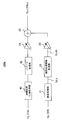
図3は信号処理部100の回路構成例を示す。なお、図3の例は、左フロントch信号FLの例であるが、図中の括弧で示すように右フロントch信号FRについても同様の回路が設けられ、同様の処理がなされる。信号処理部100は、遅延処理部21と、頭部伝達関数処理部22と、アンプ23、24と、加算器25とを備える。
FIG. 3 shows a circuit configuration example of the signal processing unit 100. The example of FIG. 3 is an example of the left front ch signal FL, but as shown by the parentheses in the figure, a similar circuit is provided for the right front ch signal FR and the same processing is performed. The signal processing unit 100 includes a delay processing unit 21, a head related transfer function processing unit 22, amplifiers 23 and 24, and an adder 25.
遅延処理部21は、サラウンドch信号SLを受け取り、これを所定の遅延時間Td遅延して遅延サラウンドch信号SLdを生成し、頭部伝達関数処理部22へ送る。所定の遅延時間Tdは、前述のように部屋7における視聴対象物距離L1に応じて決定される。
The delay processing unit 21 receives the surround ch signal SL, delays it by a predetermined delay time Td, generates a delayed surround ch signal SLd, and sends it to the head related transfer function processing unit 22. The predetermined delay time Td is determined according to the viewing object distance L1 in the room 7 as described above.
頭部伝達関数処理部22は、遅延サラウンドch信号SLdに対して、その音像を実際のセンタースピーカ5FL、5FRよりもセンター方向より、好適にはセンター方向から±10~20度の範囲内に定位させる頭部伝達関数を畳み込み演算する。そして、頭部伝達関数処理部22は、処理後の遅延サラウンド信号SLdhをアンプ23へ供給する。アンプ23は、頭部伝達関数処理後の遅延サラウンド信号SLdhを所定のレベルに増幅し、加算器25へ送る。
The head related transfer function processing unit 22 localizes the sound image of the delayed surround ch signal SLd from the center direction of the actual center speakers 5FL and 5FR, preferably within a range of ± 10 to 20 degrees from the center direction. The head-related transfer function to be convolved is calculated. Then, the head-related transfer function processing unit 22 supplies the processed delayed surround signal SLdh to the amplifier 23. The amplifier 23 amplifies the delayed surround signal SLdh after the head-related transfer function processing to a predetermined level and sends it to the adder 25.
一方、信号処理部100に入力されたフロントch信号FLはアンプ24で所定のレベルに増幅された後、加算器25へ送られる。加算器25は、頭部伝達関数処理後の遅延サラウンド信号SLdhをフロントch信号FLに加算し、フロントch信号FLxとしてDA変換器3へ出力する。
On the other hand, the front ch signal FL input to the signal processing unit 100 is amplified to a predetermined level by the amplifier 24 and then sent to the adder 25. The adder 25 adds the delayed surround signal SLdh after the head-related transfer function processing to the front ch signal FL, and outputs the result to the DA converter 3 as the front ch signal FLx.
このように、信号処理部100は、サラウンドch信号の成分を所定時間遅延し、頭部伝達関数処理した後、フロントスピーカから出力することにより、視聴位置LPにいる視聴者にセンター方向への奥行き感を与えることができる。
As described above, the signal processing unit 100 delays the component of the surround ch signal for a predetermined time, performs head-related transfer function processing, and then outputs the result from the front speaker, thereby allowing the viewer at the viewing position LP to enter the depth in the center direction. A feeling can be given.
[第2実施例]
次に第2実施例について説明する。第2実施例は、上記の第1実施例の処理を前提とする。 [Second embodiment]
Next, a second embodiment will be described. The second embodiment is premised on the processing of the first embodiment.
次に第2実施例について説明する。第2実施例は、上記の第1実施例の処理を前提とする。 [Second embodiment]
Next, a second embodiment will be described. The second embodiment is premised on the processing of the first embodiment.
第1実施例では、信号処理部100はフロントch信号に対してサラウンドch信号を加算しているが、サラウンドch信号に対しては特に処理を行っていない。第2実施例では、第1実施例の処理に加えて、信号処理部100はサラウンドch信号に対する処理を行う。具体的には、信号処理部100は、左サラウンドch信号SLの逆相信号を生成し、それを約6dB減衰させたもの(即ち、レベルを1/2に減衰させたもの)を右サラウンドch信号SRに加算する。同様に、信号処理部100は、右サラウンドch信号SRの逆相信号を生成し、それを約6dB減衰させたものを左サラウンドch信号SLに加算する。これにより、仮想音場空間8の壁8wからの反射音の広がり感が増強される。
In the first embodiment, the signal processing unit 100 adds the surround ch signal to the front ch signal, but does not particularly process the surround ch signal. In the second embodiment, in addition to the processing of the first embodiment, the signal processing unit 100 performs processing on the surround ch signal. Specifically, the signal processing unit 100 generates a reverse phase signal of the left surround ch signal SL and attenuates it by about 6 dB (that is, attenuates the level by 1/2) to the right surround ch. Add to signal SR. Similarly, the signal processing unit 100 generates a reverse phase signal of the right surround ch signal SR, and adds a signal obtained by attenuating it by about 6 dB to the left surround ch signal SL. As a result, the spread of the reflected sound from the wall 8w of the virtual sound field space 8 is enhanced.
図4は第2実施例に係る処理回路の構成を示す。この回路30は、位相反転部31、32と、アンプ33、34と、加算器35、36とを備える。左サラウンドch信号SLは、加算器35に入力されるとともに、位相反転部31に供給される。位相反転部31は、左サラウンドch信号SLの逆相信号を生成し、アンプ33に供給する。アンプ33は、供給された左サラウンドch信号SLの逆相信号を6dB減衰させ、加算器36に供給する。
FIG. 4 shows a configuration of a processing circuit according to the second embodiment. The circuit 30 includes phase inverting units 31 and 32, amplifiers 33 and 34, and adders 35 and 36. The left surround ch signal SL is input to the adder 35 and is supplied to the phase inversion unit 31. The phase inverting unit 31 generates a reverse phase signal of the left surround ch signal SL and supplies it to the amplifier 33. The amplifier 33 attenuates the reverse phase signal of the supplied left surround ch signal SL by 6 dB and supplies the attenuated signal to the adder 36.
同様に、右サラウンドch信号SRは、加算器36に入力されるとともに、位相反転部32に供給される。位相反転部32は、右サラウンドch信号SRの逆相信号を生成し、アンプ34に供給する。アンプ34は、供給された右サラウンドch信号SRの逆相信号を6dB減衰させ、加算器36に供給する。
Similarly, the right surround ch signal SR is input to the adder 36 and supplied to the phase inversion unit 32. The phase inverting unit 32 generates a reverse phase signal of the right surround ch signal SR and supplies it to the amplifier 34. The amplifier 34 attenuates the reverse phase signal of the supplied right surround ch signal SR by 6 dB and supplies the attenuated signal to the adder 36.
加算器35は、左サラウンドch信号SLに、右サラウンドchSR信号の逆相信号を加算し、左サラウンドch信号SLxとして出力する。加算器36は、右サラウンドch信号SRに、左サラウンドch信号SLの逆相信号を加算し、右サラウンドch信号SRxとして出力する。
The adder 35 adds the reverse phase signal of the right surround ch SR signal to the left surround ch signal SL, and outputs the result as the left surround ch signal SLx. The adder 36 adds the reverse phase signal of the left surround ch signal SL to the right surround ch signal SR, and outputs the result as the right surround ch signal SRx.
[第3実施例]
第1実施例では、遅延サラウンドch信号をフロントch信号に加算している。第3実施例では、これに加えて、遅延サラウンドch信号をセンターch信号も加算する。この場合、サラウンドch信号の遅延時間Tdはフロントch信号に加算される遅延サラウンド信号の遅延時間Tdと同じとする。1つの例では、左右の遅延サラウンドch信号を加算し、2で除算したものをセンターch信号に加算すればよい。 [Third embodiment]
In the first embodiment, the delayed surround ch signal is added to the front ch signal. In the third embodiment, in addition to this, the delayed surround ch signal is also added to the center ch signal. In this case, the delay time Td of the surround ch signal is the same as the delay time Td of the delayed surround signal added to the front ch signal. In one example, the left and right delayed surround ch signals may be added and the result of division by 2 added to the center ch signal.
[第4実施例]
第1実施例では、信号処理部100は、遅延サラウンドch信号が加算されるフロントch信号については特に処理を行っていない。第4実施例では、信号処理部100は、第1実施例の処理に加えて、フロントch信号に初期反射付加処理及びリバーブ処理を行う。この場合の信号処理部100aの回路構成例を図5に示す。 [Fourth embodiment]
In the first embodiment, thesignal processing unit 100 does not particularly process the front ch signal to which the delayed surround ch signal is added. In the fourth embodiment, the signal processing unit 100 performs initial reflection addition processing and reverberation processing on the front ch signal in addition to the processing in the first embodiment. FIG. 5 shows a circuit configuration example of the signal processing unit 100a in this case.
第1実施例では、信号処理部100は、遅延サラウンドch信号が加算されるフロントch信号については特に処理を行っていない。第4実施例では、信号処理部100は、第1実施例の処理に加えて、フロントch信号に初期反射付加処理及びリバーブ処理を行う。この場合の信号処理部100aの回路構成例を図5に示す。 [Fourth embodiment]
In the first embodiment, the
図3と比較するとわかるように、信号処理部100aは、フロントch信号に対して初期反射付加処理を行う初期反射付加部41と、リバーブ処理を行うリバーブ処理部42とを備える。
As can be seen from comparison with FIG. 3, the signal processing unit 100 a includes an initial reflection adding unit 41 that performs initial reflection adding processing on the front ch signal, and a reverb processing unit 42 that performs reverberation processing.
初期反射付加部41は、フロントch信号FLが仮想スピーカ5VLから出力された場合の初期反射音を算出してフロントch信号FLに加算するとともに、フロントch信号FRが仮想スピーカ5VRから出力された場合の初期反射音を算出してフロントch信号FRに加算する。
The initial reflection adding unit 41 calculates an initial reflected sound when the front ch signal FL is output from the virtual speaker 5VL, adds the initial reflected sound to the front ch signal FL, and the front ch signal FR is output from the virtual speaker 5VR. Is calculated and added to the front ch signal FR.
具体的に、初期反射付加処理部41は、まず視聴位置LPから仮想スピーカ5VL、5VRまでの距離である仮想スピーカ距離Dを視聴対象物距離L1の2倍として算出する。即ち、
D=L1×2 (3)
とする。 Specifically, the initial reflectionaddition processing unit 41 first calculates the virtual speaker distance D that is the distance from the viewing position LP to the virtual speakers 5VL and 5VR as twice the viewing object distance L1. That is,
D = L1 × 2 (3)
And
D=L1×2 (3)
とする。 Specifically, the initial reflection
D = L1 × 2 (3)
And
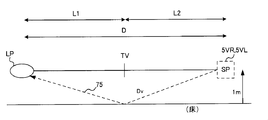
次に、初期反射付加部41は初期反射遅延量を算出する。初期反射遅延量を算出する方法を図6に示す。図6は、図2に示す部屋7及び仮想音場空間8を横方向から見た図であり、視聴位置LPとTV9との間の視聴対象物距離が「L1」、TV9と仮想スピーカ5VR又は5VLとの距離が「L2」、視聴位置LPと仮想スピーカ5VR又は5VLとの間の仮想スピーカ距離が「D」として示されている。また、上下方向においては、標準的な例として、視聴位置LP、TV9、仮想スピーカ5VL又は5VRはいずれも床から1mの高さに配置されているものとする。
Next, the initial reflection adding unit 41 calculates an initial reflection delay amount. FIG. 6 shows a method for calculating the initial reflection delay amount. FIG. 6 is a view of the room 7 and the virtual sound field space 8 shown in FIG. 2 as viewed from the horizontal direction. The viewing object distance between the viewing position LP and the TV 9 is “L1”, and the TV 9 and the virtual speaker 5VR or The distance to 5VL is indicated as “L2”, and the virtual speaker distance between the viewing position LP and the virtual speaker 5VR or 5VL is indicated as “D”. In the vertical direction, as a standard example, the viewing position LP, the TV 9, and the virtual speaker 5VL or 5VR are all disposed at a height of 1 m from the floor.
この条件において、破線75は仮想スピーカ5FL又は5FRからの初期反射音(床による反射とする)の経路を示す。よって、破線75に示す初期反射音の経路の距離Dvは、
Dv=(1+(D/2)2)0.5×2 (4)
となる。一方、直接音の経路の距離は仮想スピーカ距離Dに等しい。よって、直接音に対する初期反射音の遅延量である初期反射遅延量Τrefは、初期反射音の距離Dvと直接音の距離Dとの差に基づいて、
Τref=(Dv-D)/c (c:音速) (5)
となる。なお、初期反射音の距離Dvと直接音の距離Dとの差は、仮想スピーカ距離Dが長くなるほど小さくなる。また、上記の式において、仮想スピーカからの直接音距離D及び初期反射音距離Dvは、自動音場補正などにより距離補正されているものとする。そして、初期反射付加処理部41は、こうして得られた初期反射遅延量Τrefをメモリなどに記憶する。 Under this condition, abroken line 75 indicates the path of the initial reflected sound (referred to as floor reflection) from the virtual speaker 5FL or 5FR. Therefore, the distance Dv of the path of the initial reflected sound shown by the broken line 75 is
Dv = (1+ (D / 2) 2 ) 0.5 × 2 (4)
It becomes. On the other hand, the distance of the direct sound path is equal to the virtual speaker distance D. Therefore, the initial reflection delay amount Τref, which is the delay amount of the initial reflected sound with respect to the direct sound, is based on the difference between the distance Dv of the initial reflected sound and the distance D of the direct sound.
Τref = (Dv−D) / c (c: speed of sound) (5)
It becomes. The difference between the initial reflected sound distance Dv and the direct sound distance D decreases as the virtual speaker distance D increases. In the above equation, it is assumed that the direct sound distance D and the initial reflected sound distance Dv from the virtual speaker are corrected by automatic sound field correction or the like. The initial reflectionaddition processing unit 41 stores the initial reflection delay amount Τref thus obtained in a memory or the like.
Dv=(1+(D/2)2)0.5×2 (4)
となる。一方、直接音の経路の距離は仮想スピーカ距離Dに等しい。よって、直接音に対する初期反射音の遅延量である初期反射遅延量Τrefは、初期反射音の距離Dvと直接音の距離Dとの差に基づいて、
Τref=(Dv-D)/c (c:音速) (5)
となる。なお、初期反射音の距離Dvと直接音の距離Dとの差は、仮想スピーカ距離Dが長くなるほど小さくなる。また、上記の式において、仮想スピーカからの直接音距離D及び初期反射音距離Dvは、自動音場補正などにより距離補正されているものとする。そして、初期反射付加処理部41は、こうして得られた初期反射遅延量Τrefをメモリなどに記憶する。 Under this condition, a
Dv = (1+ (D / 2) 2 ) 0.5 × 2 (4)
It becomes. On the other hand, the distance of the direct sound path is equal to the virtual speaker distance D. Therefore, the initial reflection delay amount Τref, which is the delay amount of the initial reflected sound with respect to the direct sound, is based on the difference between the distance Dv of the initial reflected sound and the distance D of the direct sound.
Τref = (Dv−D) / c (c: speed of sound) (5)
It becomes. The difference between the initial reflected sound distance Dv and the direct sound distance D decreases as the virtual speaker distance D increases. In the above equation, it is assumed that the direct sound distance D and the initial reflected sound distance Dv from the virtual speaker are corrected by automatic sound field correction or the like. The initial reflection
初期反射付加処理部41のメモリには、上記のようにして得られた仮想スピーカ距離D及び初期反射遅延量Τrefが記憶されている。加えて、メモリには、仮想スピーカ距離Dと初期反射レベルLrefとの関係を規定したマップなどが記憶されている。具体的には、仮想スピーカ距離Dが短いほど、初期反射レベルLrefを小さくする。
In the memory of the initial reflection addition processing unit 41, the virtual speaker distance D and the initial reflection delay amount Τref obtained as described above are stored. In addition, the memory stores a map that defines the relationship between the virtual speaker distance D and the initial reflection level Lref. Specifically, the initial reflection level Lref is reduced as the virtual speaker distance D is shorter.
こうして、仮想スピーカ距離D、初期反射遅延量Τref、及び、初期反射レベルLrefを規定するマップなどがメモリに記憶された状態となる。そして、初期反射付加処理部41は、初期反射遅延量Tref及び初期反射レベルLrefに応じた初期反射音を生成し、フロントch信号FL又はFRに加算する。
Thus, the virtual speaker distance D, the initial reflection delay amount Τref, the map that defines the initial reflection level Lref, and the like are stored in the memory. Then, the initial reflection addition processing unit 41 generates an initial reflected sound corresponding to the initial reflection delay amount Tref and the initial reflection level Lref, and adds it to the front ch signal FL or FR.
初期反射音が付加されたフロントch信号FL又はFRは、リバーブ処理部42に送られる。リバーブ処理部42は、入力されたフロントch信号FL又はFRに対して残響成分を付加するリバーブ処理を行い、アンプ24を介して加算器25へ送る。こうして、第4実施例では、初期反射付加処理及びリバーブ処理が施されたフロントch信号に対して、遅延処理及び頭部伝達関数処理が施されたサラウンドch信号が付加され、フロントスピーカから出力される。
The front ch signal FL or FR to which the initial reflected sound is added is sent to the reverb processing unit 42. The reverberation processing unit 42 performs reverberation processing for adding a reverberation component to the input front ch signal FL or FR, and sends it to the adder 25 via the amplifier 24. Thus, in the fourth embodiment, the surround ch signal subjected to the delay process and the head related transfer function process is added to the front ch signal subjected to the initial reflection addition process and the reverb process, and is output from the front speaker. The
これにより、壁7wの向こう側の仮想音場空間8と、壁7wより手前の実音場空間との音場のつながりを改善、向上することができる。即ち、第1実施例の遅延処理及び頭部伝達関数処理を行わずにフロントch信号に対して初期反射付加処理及びリバーブ処理を行った場合、壁7wの奥に仮想音場空間はできるが、壁より手間の実音場空間とは基本的に無関係なため、仮想音場空間と実音場空間とが分離されてしまい、違和感が生じる。これに対し、第1実施例の遅延処理及び頭部伝達関数処理が施されたサラウンドch信号を、本実施例のように初期反射付加処理及びリバーブ処理が施されたフロントch信号に加算することにより、サラウンドch信号という1つの信号が結び付け役となって、その分離感を和らげることができる。その結果、仮想音場空間と実音場空間とを含む全体の音場空間の一体感を高めることができる。
Thereby, the connection of the sound field between the virtual sound field space 8 on the other side of the wall 7w and the real sound field space in front of the wall 7w can be improved and improved. That is, when the initial reflection addition process and the reverb process are performed on the front ch signal without performing the delay process and the head-related transfer function process of the first embodiment, a virtual sound field space is formed at the back of the wall 7w. Since it is basically irrelevant to the real sound field space, which is more troublesome than the wall, the virtual sound field space and the real sound field space are separated, resulting in a sense of discomfort. On the other hand, the surround ch signal subjected to the delay process and the head-related transfer function process of the first embodiment is added to the front ch signal subjected to the initial reflection addition process and the reverb process as in the present embodiment. Thus, one signal called a surround ch signal serves as a tie, and the separation feeling can be reduced. As a result, it is possible to enhance the sense of unity of the entire sound field space including the virtual sound field space and the real sound field space.
[第5実施例]
第5実施例では、スピーカ距離検出機能により視聴対象物距離L1を自動的に検出する。具体的には、図1において、信号処理部100は、予め用意されたテスト信号、好ましくはパルス性のテスト信号をDA変換器3、アンプ4を介してフロントスピーカ5FL又は5FRから部屋7内へテスト音として放出する。マイク6は視聴位置LPに配置されており、部屋7へ放出されたテスト音を集音し、信号処理部100へ送る。信号処理部100は、集音されたテスト音をディジタル信号に変換し、マイク6により集音されたテスト信号(以下、「集音テスト信号」と呼ぶ。)とする。 [Fifth embodiment]
In the fifth embodiment, the viewing object distance L1 is automatically detected by the speaker distance detection function. Specifically, in FIG. 1, thesignal processing unit 100 sends a test signal prepared in advance, preferably a pulsed test signal, from the front speaker 5FL or 5FR into the room 7 via the DA converter 3 and the amplifier 4. Released as a test sound. The microphone 6 is disposed at the viewing position LP, collects the test sound emitted to the room 7, and sends it to the signal processing unit 100. The signal processing unit 100 converts the collected test sound into a digital signal and uses it as a test signal collected by the microphone 6 (hereinafter referred to as “sound collection test signal”).
第5実施例では、スピーカ距離検出機能により視聴対象物距離L1を自動的に検出する。具体的には、図1において、信号処理部100は、予め用意されたテスト信号、好ましくはパルス性のテスト信号をDA変換器3、アンプ4を介してフロントスピーカ5FL又は5FRから部屋7内へテスト音として放出する。マイク6は視聴位置LPに配置されており、部屋7へ放出されたテスト音を集音し、信号処理部100へ送る。信号処理部100は、集音されたテスト音をディジタル信号に変換し、マイク6により集音されたテスト信号(以下、「集音テスト信号」と呼ぶ。)とする。 [Fifth embodiment]
In the fifth embodiment, the viewing object distance L1 is automatically detected by the speaker distance detection function. Specifically, in FIG. 1, the
そして、信号処理部100は、集音テスト信号と、フロントスピーカから出力されたテスト信号(以下、「出力テスト信号」と呼ぶ。)とを比較する。出力テスト信号に対する集音テスト信号の時間的な遅れは、マイク6、信号処理部100、DA変換器3、アンプ4及びスピーカ5により構成される系内での遅延分を無視すれば、左右のスピーカ5FL又は5FRと視聴位置LPと間を音波が伝搬する時間に相当する。よって、信号処理部100は、出力テスト信号と集音テスト信号との時間差に音速を乗算し、視聴位置LPと左右のスピーカ5FL及び5FRとの距離を算出する。
Then, the signal processing unit 100 compares the sound collection test signal with the test signal output from the front speaker (hereinafter referred to as “output test signal”). The time delay of the sound collection test signal with respect to the output test signal can be determined by ignoring the delay in the system constituted by the microphone 6, the signal processing unit 100, the DA converter 3, the amplifier 4 and the speaker 5. This corresponds to the time for sound waves to propagate between the speaker 5FL or 5FR and the viewing position LP. Therefore, the signal processing unit 100 calculates the distance between the viewing position LP and the left and right speakers 5FL and 5FR by multiplying the time difference between the output test signal and the sound collection test signal by the sound speed.
次に、信号処理部100は、視聴位置LPとTV9又はセンタースピーカ5Cとの距離である視聴対象物距離L1を算出する。図7は視聴対象物距離を算出する方法を示す。視聴位置LPと左フロントスピーカ5FLとの距離を「Lfl」とし、視聴位置LPと右フロントスピーカ5FRとの距離を「Lfr」とする。標準的な配置として、センター方向と、視聴位置LPと左右のフロントスピーカ5FL又は5FRとを結ぶ方向とのなす角を30°と仮定すると、視聴対象物距離L1は以下の式により求められる。
Next, the signal processing unit 100 calculates a viewing object distance L1 that is a distance between the viewing position LP and the TV 9 or the center speaker 5C. FIG. 7 shows a method of calculating the viewing object distance. The distance between the viewing position LP and the left front speaker 5FL is “Lfl”, and the distance between the viewing position LP and the right front speaker 5FR is “Lfr”. Assuming that the angle between the center direction and the direction connecting the viewing position LP and the left and right front speakers 5FL or 5FR is 30 ° as a standard arrangement, the viewing object distance L1 is obtained by the following equation.
L1=(Lfl+Lfr)/2×(√3/2) (6)
こうして信号処理部100は視聴対象物距離L1を算出する。そして、信号処理部100は、得られた視聴対象物距離L1を用いて、前述のようにサラウンドch信号の遅延時間Tdを決定する。 L1 = (Lfl + Lfr) / 2 × (√3 / 2) (6)
Thus, thesignal processing unit 100 calculates the viewing object distance L1. Then, the signal processing unit 100 determines the delay time Td of the surround ch signal as described above using the obtained viewing target object distance L1.
こうして信号処理部100は視聴対象物距離L1を算出する。そして、信号処理部100は、得られた視聴対象物距離L1を用いて、前述のようにサラウンドch信号の遅延時間Tdを決定する。 L1 = (Lfl + Lfr) / 2 × (√3 / 2) (6)
Thus, the
なお、この例において、信号処理部100が視聴位置LPと左右のフロントスピーカ5FL及び5FRとの距離を用いて視聴対象物距離L1を算出しているのは、部屋7に設定される再生システムが5ch構成ではなく、センタースピーカを含まない4ch又は2chの場合があることを考慮したからである。即ち、上記の方法によれば、センターchを含まないスピーカ構成であったとしても、左右のフロントスピーカを用いて視聴対象物距離L1を求めることができる。
In this example, the signal processing unit 100 calculates the viewing object distance L1 using the distance between the viewing position LP and the left and right front speakers 5FL and 5FR because the playback system set in the room 7 This is because it is considered that there is a case of 4ch or 2ch not including the center speaker, instead of the 5ch configuration. That is, according to the above method, even if the speaker configuration does not include the center channel, the viewing object distance L1 can be obtained using the left and right front speakers.
本発明は、AVレシーバー、一般のTV、DVD/BDプレイヤーなど、映像とともにマルチチャンネルの音声信号を再生する装置に利用することができる。
The present invention can be used for an apparatus that reproduces a multi-channel audio signal together with video, such as an AV receiver, a general TV, a DVD / BD player, and the like.
1 音声再生装置
2 デコーダ
3 DA変換器
4 アンプ
5 スピーカ
6 マイク
100 信号処理部
LP 視聴位置 DESCRIPTION OFSYMBOLS 1 Audio | voice reproduction apparatus 2 Decoder 3 DA converter 4 Amplifier 5 Speaker 6 Microphone 100 Signal processing part LP Viewing position
2 デコーダ
3 DA変換器
4 アンプ
5 スピーカ
6 マイク
100 信号処理部
LP 視聴位置 DESCRIPTION OF
Claims (11)
- 音声信号処理装置であって、
フロントチャンネル信号及びサラウンドチャンネル信号を含む入力信号を受け取る入力部と、
サラウンドチャンネル信号を所定の遅延時間遅延して遅延サラウンドチャンネル信号を生成する遅延手段と、
フロントチャンネル信号に対して、初期反射処理及び/又はリバーブ処理により仮想音場空間を作り出す処理を行う処理手段と、
前記遅延サラウンドチャンネル信号を、前記処理手段により処理されたフロントチャンネル信号に加算する加算手段と、
前記加算手段より出力されたフロントチャンネル信号、及び、サラウンドチャンネル信号を出力する出力手段と、を備えることを特徴とする音声信号処理装置。 An audio signal processing device,
An input for receiving an input signal including a front channel signal and a surround channel signal;
Delay means for delaying the surround channel signal by a predetermined delay time to generate a delayed surround channel signal;
Processing means for processing the front channel signal to create a virtual sound field space by initial reflection processing and / or reverb processing;
Adding means for adding the delayed surround channel signal to the front channel signal processed by the processing means;
An audio signal processing apparatus comprising: a front channel signal output from the adding means; and an output means for outputting a surround channel signal. - 前記表示装置はセンタースピーカを備え、
前記加算手段は、前記遅延サラウンドチャンネル信号をセンターチャンネル信号に加算することを特徴とする請求項1に記載の音声信号処理装置。 The display device includes a center speaker,
The audio signal processing apparatus according to claim 1, wherein the adding means adds the delayed surround channel signal to a center channel signal. - 前記所定の遅延時間は、30~40msであることを特徴とする請求項1又は2に記載の音声信号処理装置。 3. The audio signal processing apparatus according to claim 1, wherein the predetermined delay time is 30 to 40 ms.
- モニタと、左右のフロントスピーカ及び左右のサラウンドスピーカを備える表示装置に用いられる請求項1に記載の音声信号処理装置。 The audio signal processing device according to claim 1, wherein the audio signal processing device is used in a display device including a monitor, left and right front speakers, and left and right surround speakers.
- 視聴対象物位置と視聴位置との距離である視聴対象物距離を検出する視聴対象物距離検出手段を備え、
前記所定の遅延時間は、前記視聴対象物距離の4~5倍の距離による音波遅延に相当する遅延時間であることを特徴とする請求項3に記載の音声信号処理装置。 A viewing object distance detecting means for detecting a viewing object distance that is a distance between the viewing object position and the viewing position;
4. The audio signal processing apparatus according to claim 3, wherein the predetermined delay time is a delay time corresponding to a sound wave delay caused by a distance of 4 to 5 times the viewing object distance. - 視聴対象物位置と視聴位置との距離である視聴対象物距離を検出する視聴対象物距離検出手段と、
前記視聴対象物距離に基づいて、視聴位置から見てモニタの後方に仮想スピーカを想定し、当該仮想スピーカと視聴位置との距離である仮想スピーカ距離を前記視聴対象物距離の2倍に決定する仮想スピーカ距離決定手段と、を備え、
前記遅延手段は、前記仮想スピーカ距離に基づいて前記所定の遅延時間を決定することを特徴とする請求項3に記載の音声信号処理装置。 Viewing object distance detecting means for detecting a viewing object distance, which is a distance between the viewing object position and the viewing position;
Based on the viewing object distance, a virtual speaker is assumed behind the monitor when viewed from the viewing position, and the virtual speaker distance that is the distance between the virtual speaker and the viewing position is determined to be twice the viewing object distance. Virtual speaker distance determining means,
The audio signal processing apparatus according to claim 3, wherein the delay unit determines the predetermined delay time based on the virtual speaker distance. - 前記視聴対象物距離検出手段は、
前記視聴位置を含む空間にテスト音を出力する放音手段と、
前記放音手段により放音されたテスト音を前記視聴位置において集音する集音手段と、
前記放音手段により放音されたテスト音に対する、前記集音手段により集音されたテスト音の遅延量に基づいて、前記視聴位置とフロントスピーカとの距離を算出し、当該フロントスピーカの距離に基づいて前記視聴対象物距離を算出する算出手段と、を備えることを特徴とする請求項5又は6に記載の音声信号処理装置。 The viewing object distance detecting means includes
A sound emitting means for outputting a test sound in a space including the viewing position;
Sound collecting means for collecting the test sound emitted by the sound emitting means at the viewing position;
Based on the delay amount of the test sound collected by the sound collecting means with respect to the test sound emitted by the sound emitting means, the distance between the viewing position and the front speaker is calculated, and the distance between the front speakers is calculated. The audio signal processing apparatus according to claim 5, further comprising: a calculation unit that calculates the viewing object distance based on the calculation object distance. - 左右のフロントスピーカから出力される音の音像が実際の左右のフロントスピーカの位置よりも前記モニタの中央よりに定位するように、前記遅延サラウンドチャンネル信号に対して頭部伝達関数処理を行う頭部伝達関数処理手段を備えることを特徴とする請求項3乃至7のいずれか一項に記載の音声信号処理装置。 A head that performs head-related transfer function processing on the delayed surround channel signal so that the sound image of the sound output from the left and right front speakers is localized from the center of the monitor rather than the actual position of the left and right front speakers. 8. The audio signal processing apparatus according to claim 3, further comprising transfer function processing means.
- 左サラウンドチャンネル信号の位相を反転させ、所定量減衰させた信号を右サラウンドチャンネル信号に加算する手段と、
右サラウンドチャンネル信号の位相を反転させ、前記所定量減衰させた信号を左サラウンドチャンネル信号に加算する手段と、を備えることを特徴とする請求項3乃至8のいずれか一項に記載の音声信号処理装置。 Means for inverting the phase of the left surround channel signal and adding a signal attenuated by a predetermined amount to the right surround channel signal;
9. The audio signal according to claim 3, further comprising means for inverting the phase of the right surround channel signal and adding the signal attenuated by the predetermined amount to the left surround channel signal. Processing equipment. - モニタと、
左右のフロントスピーカ及び左右のサラウンドスピーカと、
請求項1に記載の音声信号処理装置と、を備えることを特徴とする表示装置。 A monitor,
Left and right front speakers and left and right surround speakers;
A display device comprising: the audio signal processing device according to claim 1. - コンピュータを備える装置により実行される音声信号処理プログラムであって、
フロントチャンネル信号及びサラウンドチャンネル信号を含む入力信号を受け取る入力手段、
サラウンドチャンネル信号を所定の遅延時間遅延して遅延サラウンドチャンネル信号を生成する遅延手段、
フロントチャンネル信号に対して、初期反射処理及び/又はリバーブ処理により仮想音場空間を作り出す処理を行う処理手段、
前記遅延サラウンドチャンネル信号を、前記処理手段により処理されたフロントチャンネル信号に加算する加算手段、
前記加算手段より出力されたフロントチャンネル信号、及び、サラウンドチャンネル信号を出力する出力手段、として前記コンピュータを機能させることを特徴とする音声信号処理プログラム。 An audio signal processing program executed by an apparatus including a computer,
Input means for receiving an input signal including a front channel signal and a surround channel signal;
Delay means for delaying the surround channel signal by a predetermined delay time to generate a delayed surround channel signal;
Processing means for performing processing for creating a virtual sound field space by initial reflection processing and / or reverberation processing on the front channel signal;
Adding means for adding the delayed surround channel signal to the front channel signal processed by the processing means;
An audio signal processing program for causing the computer to function as output means for outputting a front channel signal and a surround channel signal output from the adding means.
Priority Applications (2)
| Application Number | Priority Date | Filing Date | Title |
|---|---|---|---|
| PCT/JP2011/060416 WO2012147196A1 (en) | 2011-04-28 | 2011-04-28 | Sound signal processing device and sound signal processing program |
| JP2011546511A JP4981995B1 (en) | 2011-04-28 | 2011-04-28 | Audio signal processing apparatus and audio signal processing program |
Applications Claiming Priority (1)
| Application Number | Priority Date | Filing Date | Title |
|---|---|---|---|
| PCT/JP2011/060416 WO2012147196A1 (en) | 2011-04-28 | 2011-04-28 | Sound signal processing device and sound signal processing program |
Publications (1)
| Publication Number | Publication Date |
|---|---|
| WO2012147196A1 true WO2012147196A1 (en) | 2012-11-01 |
Family
ID=46678930
Family Applications (1)
| Application Number | Title | Priority Date | Filing Date |
|---|---|---|---|
| PCT/JP2011/060416 WO2012147196A1 (en) | 2011-04-28 | 2011-04-28 | Sound signal processing device and sound signal processing program |
Country Status (2)
| Country | Link |
|---|---|
| JP (1) | JP4981995B1 (en) |
| WO (1) | WO2012147196A1 (en) |
Cited By (1)
| Publication number | Priority date | Publication date | Assignee | Title |
|---|---|---|---|---|
| EP4061018A3 (en) * | 2021-03-19 | 2023-04-12 | Yamaha Corporation | Audio signal processing method, audio signal processing apparatus and audio signal processing program |
Citations (7)
| Publication number | Priority date | Publication date | Assignee | Title |
|---|---|---|---|---|
| JPS63151300A (en) * | 1986-12-16 | 1988-06-23 | Sony Corp | Acoustic electronic equipment |
| JPH05207597A (en) * | 1992-01-30 | 1993-08-13 | Matsushita Electric Ind Co Ltd | Sound field reproduction device |
| JPH09252499A (en) * | 1996-03-14 | 1997-09-22 | Mitsubishi Electric Corp | Multi-channel sound reproducing device |
| WO1999035885A1 (en) * | 1998-01-08 | 1999-07-15 | Sanyo Electric Co., Ltd. | Sound image localizing device |
| JP2007266967A (en) * | 2006-03-28 | 2007-10-11 | Yamaha Corp | Sound image localizer and multichannel audio reproduction device |
| JP2007300403A (en) * | 2006-04-28 | 2007-11-15 | Yamaha Corp | Sound field controller |
| JP2010200280A (en) * | 2009-02-27 | 2010-09-09 | Canon Inc | Output system, output control device, output control method, and program |
Family Cites Families (3)
| Publication number | Priority date | Publication date | Assignee | Title |
|---|---|---|---|---|
| JP2001346298A (en) * | 2000-06-06 | 2001-12-14 | Fuji Xerox Co Ltd | Binaural reproducing device and sound source evaluation aid method |
| JP5245368B2 (en) * | 2007-11-14 | 2013-07-24 | ヤマハ株式会社 | Virtual sound source localization device |
| JP2009147812A (en) * | 2007-12-17 | 2009-07-02 | Fujitsu Ten Ltd | Acoustic system, acoustic control method and setting method of acoustic system |
-
2011
- 2011-04-28 JP JP2011546511A patent/JP4981995B1/en not_active Expired - Fee Related
- 2011-04-28 WO PCT/JP2011/060416 patent/WO2012147196A1/en active Application Filing
Patent Citations (7)
| Publication number | Priority date | Publication date | Assignee | Title |
|---|---|---|---|---|
| JPS63151300A (en) * | 1986-12-16 | 1988-06-23 | Sony Corp | Acoustic electronic equipment |
| JPH05207597A (en) * | 1992-01-30 | 1993-08-13 | Matsushita Electric Ind Co Ltd | Sound field reproduction device |
| JPH09252499A (en) * | 1996-03-14 | 1997-09-22 | Mitsubishi Electric Corp | Multi-channel sound reproducing device |
| WO1999035885A1 (en) * | 1998-01-08 | 1999-07-15 | Sanyo Electric Co., Ltd. | Sound image localizing device |
| JP2007266967A (en) * | 2006-03-28 | 2007-10-11 | Yamaha Corp | Sound image localizer and multichannel audio reproduction device |
| JP2007300403A (en) * | 2006-04-28 | 2007-11-15 | Yamaha Corp | Sound field controller |
| JP2010200280A (en) * | 2009-02-27 | 2010-09-09 | Canon Inc | Output system, output control device, output control method, and program |
Cited By (1)
| Publication number | Priority date | Publication date | Assignee | Title |
|---|---|---|---|---|
| EP4061018A3 (en) * | 2021-03-19 | 2023-04-12 | Yamaha Corporation | Audio signal processing method, audio signal processing apparatus and audio signal processing program |
Also Published As
| Publication number | Publication date |
|---|---|
| JPWO2012147196A1 (en) | 2014-07-28 |
| JP4981995B1 (en) | 2012-07-25 |
Similar Documents
| Publication | Publication Date | Title |
|---|---|---|
| EP2061279B1 (en) | Virtual sound source localization apparatus | |
| JP5944840B2 (en) | Stereo sound reproduction method and apparatus | |
| JP2012235456A (en) | Voice signal processing device, and voice signal processing program | |
| KR101490725B1 (en) | A video display apparatus, an audio-video system, a method for sound reproduction, and a sound reproduction system for localized perceptual audio | |
| JP5533248B2 (en) | Audio signal processing apparatus and audio signal processing method | |
| JP5865899B2 (en) | Stereo sound reproduction method and apparatus | |
| JP4273343B2 (en) | Playback apparatus and playback method | |
| JP2007266967A (en) | Sound image localizer and multichannel audio reproduction device | |
| JP6246922B2 (en) | Acoustic signal processing method | |
| JPWO2010076850A1 (en) | Sound field control apparatus and sound field control method | |
| JP5944403B2 (en) | Acoustic rendering apparatus and acoustic rendering method | |
| US10547962B2 (en) | Speaker arranged position presenting apparatus | |
| JP2005287002A (en) | Stereophonic acoustic reproducing system and stereophonic acoustic reproducing apparatus | |
| JP2008312096A (en) | Acoustic playback apparatus, and television receiver | |
| JP5533282B2 (en) | Sound playback device | |
| JP2012049663A (en) | Ceiling speaker system | |
| JP4981995B1 (en) | Audio signal processing apparatus and audio signal processing program | |
| JP6550756B2 (en) | Audio signal processor | |
| US9351074B2 (en) | Audio system and audio characteristic control device | |
| JP2005286828A (en) | Audio reproducing apparatus | |
| JP2007081710A (en) | Signal processing apparatus | |
| JP2011004261A (en) | Av amplifier apparatus | |
| JPH08140200A (en) | Three-dimensional sound image controller | |
| JP2013176170A (en) | Reproduction device and reproduction method | |
| JP5194614B2 (en) | Sound field generator |
Legal Events
| Date | Code | Title | Description |
|---|---|---|---|
| ENP | Entry into the national phase |
Ref document number: 2011546511 Country of ref document: JP Kind code of ref document: A |
|
| 121 | Ep: the epo has been informed by wipo that ep was designated in this application |
Ref document number: 11864400 Country of ref document: EP Kind code of ref document: A1 |
|
| NENP | Non-entry into the national phase |
Ref country code: DE |
|
| 122 | Ep: pct application non-entry in european phase |
Ref document number: 11864400 Country of ref document: EP Kind code of ref document: A1 |