WO2012144516A1 - 蓄電デバイスの状態検知方法及び状態検知装置 - Google Patents
蓄電デバイスの状態検知方法及び状態検知装置 Download PDFInfo
- Publication number
- WO2012144516A1 WO2012144516A1 PCT/JP2012/060446 JP2012060446W WO2012144516A1 WO 2012144516 A1 WO2012144516 A1 WO 2012144516A1 JP 2012060446 W JP2012060446 W JP 2012060446W WO 2012144516 A1 WO2012144516 A1 WO 2012144516A1
- Authority
- WO
- WIPO (PCT)
- Prior art keywords
- ocv
- charge
- storage device
- history
- discharge
- Prior art date
- Legal status (The legal status is an assumption and is not a legal conclusion. Google has not performed a legal analysis and makes no representation as to the accuracy of the status listed.)
- Ceased
Links
Images




Classifications
-
- H—ELECTRICITY
- H01—ELECTRIC ELEMENTS
- H01M—PROCESSES OR MEANS, e.g. BATTERIES, FOR THE DIRECT CONVERSION OF CHEMICAL ENERGY INTO ELECTRICAL ENERGY
- H01M10/00—Secondary cells; Manufacture thereof
- H01M10/42—Methods or arrangements for servicing or maintenance of secondary cells or secondary half-cells
- H01M10/48—Accumulators combined with arrangements for measuring, testing or indicating the condition of cells, e.g. the level or density of the electrolyte
-
- G—PHYSICS
- G01—MEASURING; TESTING
- G01R—MEASURING ELECTRIC VARIABLES; MEASURING MAGNETIC VARIABLES
- G01R31/00—Arrangements for testing electric properties; Arrangements for locating electric faults; Arrangements for electrical testing characterised by what is being tested not provided for elsewhere
- G01R31/36—Arrangements for testing, measuring or monitoring the electrical condition of accumulators or electric batteries, e.g. capacity or state of charge [SoC]
- G01R31/382—Arrangements for monitoring battery or accumulator variables, e.g. SoC
- G01R31/3835—Arrangements for monitoring battery or accumulator variables, e.g. SoC involving only voltage measurements
-
- H—ELECTRICITY
- H01—ELECTRIC ELEMENTS
- H01M—PROCESSES OR MEANS, e.g. BATTERIES, FOR THE DIRECT CONVERSION OF CHEMICAL ENERGY INTO ELECTRICAL ENERGY
- H01M10/00—Secondary cells; Manufacture thereof
- H01M10/42—Methods or arrangements for servicing or maintenance of secondary cells or secondary half-cells
- H01M10/44—Methods for charging or discharging
-
- G—PHYSICS
- G01—MEASURING; TESTING
- G01R—MEASURING ELECTRIC VARIABLES; MEASURING MAGNETIC VARIABLES
- G01R31/00—Arrangements for testing electric properties; Arrangements for locating electric faults; Arrangements for electrical testing characterised by what is being tested not provided for elsewhere
- G01R31/36—Arrangements for testing, measuring or monitoring the electrical condition of accumulators or electric batteries, e.g. capacity or state of charge [SoC]
- G01R31/3644—Constructional arrangements
- G01R31/3648—Constructional arrangements comprising digital calculation means, e.g. for performing an algorithm
-
- Y—GENERAL TAGGING OF NEW TECHNOLOGICAL DEVELOPMENTS; GENERAL TAGGING OF CROSS-SECTIONAL TECHNOLOGIES SPANNING OVER SEVERAL SECTIONS OF THE IPC; TECHNICAL SUBJECTS COVERED BY FORMER USPC CROSS-REFERENCE ART COLLECTIONS [XRACs] AND DIGESTS
- Y02—TECHNOLOGIES OR APPLICATIONS FOR MITIGATION OR ADAPTATION AGAINST CLIMATE CHANGE
- Y02E—REDUCTION OF GREENHOUSE GAS [GHG] EMISSIONS, RELATED TO ENERGY GENERATION, TRANSMISSION OR DISTRIBUTION
- Y02E60/00—Enabling technologies; Technologies with a potential or indirect contribution to GHG emissions mitigation
- Y02E60/10—Energy storage using batteries
Definitions
- the present invention relates to a state detection method and a state detection device for a power storage device, and particularly to a state detection method and a state detection device for a power storage device that accurately determine a charge / discharge history that governs a change in the internal state of the power storage device.
- power storage devices have been used in various fields, and various types of capacities, dimensions, weights, and the like have been provided. Some small and small-capacity power storage devices are used for portable electric devices and information terminals. Large and large-capacity power storage devices are used for backup power supplies and power supply for electric forklifts during power outages. There is something.
- Patent Document 1 discloses that between the open-circuit voltage (OCV: Open ⁇ ⁇ Circuit Voltage) and the remaining capacity (SOC: State of charge) when the liquid lead-acid battery is sufficiently stabilized after stopping charging and discharging. It is described that there is a relationship corresponding to 1: 1 as shown, and a technique for detecting the state of the power storage device using such a relationship between OCV and SOC at the time of stability is described.
- OCV Open ⁇ ⁇ Circuit Voltage
- SOC State of charge
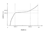
- FIG. 13 shows the relationship between SOC and stable OCV in an iron phosphate Li-ion battery.
- SOC_1 and SOC_2 are, for example, about 40% and 75%, respectively, and the change in the stable OCV is small in a relatively large SOC range of about 35%. Therefore, when the SOC is in the range of SOC_1 to SOC_2, there is a problem that it is difficult to obtain the SOC with sufficient accuracy even if the SOC is obtained by measuring the OCV at the time of stability.
- a state quantity that can more appropriately indicate the change in the internal state based on the charging / discharging history of the power storage device instead of the stable OCV, a state quantity that can more appropriately indicate the change in the internal state based on the charging / discharging history of the power storage device. It is preferable to calculate the SOC using this state quantity.
- a method for determining a charge / discharge history such as whether a power storage device has a charge history or a discharge history, has not been known so far. The device status was detected. Therefore, the SOC cannot be obtained with sufficient accuracy depending on the charge / discharge history.
- an object of the present invention is to provide a state detection method and a state detection device for a power storage device that can determine the charge / discharge history of the power storage device with high accuracy.
- 1st aspect of the state detection method of the electrical storage device of this invention is a state detection method of the electrical storage device which determines the charging / discharging log
- OCV open circuit voltage
- the history determination state quantity is an OCV integrated value calculated by time-integrating the OCV measurement value over a first period after application of the probe pulse.
- the reference data is a threshold value for the OCV integral value, and the charge / discharge history is determined to be a charge history or a discharge history by comparing the OCV integral value with the reference data.
- the history determination state quantity is an OCV change integration value obtained by time-integrating a change quantity from the predetermined reference OCV of the OCV measurement value
- the reference data Is a threshold for the OCV change integration value
- the OCV measurement value obtained when the first period after application of the probe pulse has passed is obtained as the reference OCV
- the OCV measurement value is time-integrated OCV Subtracting a value obtained by multiplying the reference OCV by the time length of the first period from an integral value to calculate the OCV change integral value, and comparing the OCV change integral value with the reference data to thereby calculate the charge / discharge history. Is determined to be a charge history or a discharge history.
- a predetermined first threshold and a second threshold larger than the first threshold are set in advance as the reference data, and the OCV integrated value or the OCV change is set.
- the charge / discharge history is determined as the discharge history
- the OCV integrated value or the OCV change integrated value is larger than the second threshold
- the charge / discharge history is determined as the charging history. It is characterized by determining.
- the history determination state quantity is a voltage drop amount that is a difference between the OCV measurement value and a predetermined reference OCV
- the reference data is a voltage drop It is a function or a table representing a change in amount of time
- the voltage drop amount is compared with the reference data corresponding to an elapsed time from the charge / discharge stop, and the charge / discharge is performed when the voltage drop amount is smaller than the reference data.
- the history is determined as the discharge history
- the charge / discharge history is determined as the charge history when the voltage drop amount is larger than the reference data.
- Another aspect of the method for detecting a state of an electricity storage device according to the present invention is characterized in that charging or discharging of the first capacity is 5% or less of a new equivalent capacity of the electricity storage device.
- Another aspect of the method for detecting the state of the electricity storage device of the present invention is characterized in that the charge / discharge stop is determined when the measured current value of the electricity storage device is equal to or less than a predetermined stop-time current threshold.
- the SOC of the electricity storage device is calculated from the OCV integrated value, the OCV change integrated value, or the reference OCV using a preset remaining capacity (SOC) calculation formula.
- charging or discharging of a second capacity is applied to the electricity storage device depending on whether the charge / discharge history is a charge history or a discharge history, and charging of the second capacity is performed.
- the OCV integrated value or the OCV change integrated value and the reference OCV are obtained after the discharge is applied, and the electricity storage is performed from the OCV integrated value, the OCV change integrated value, or the reference OCV using a preset SOC calculation formula. The SOC of the device is calculated.
- a charge of a second capacity is applied to the electricity storage device, or
- the charge / discharge history is the discharge history and the probe pulse is the charge of the first capacity
- the discharge of the second capacity is applied to the power storage device, and the OCV integrated value or the An OCV change integration value and the reference OCV are obtained, and the SOC of the electricity storage device is calculated from the OCV integration value, the OCV change integration value, or the reference OCV using a preset SOC calculation formula.
- the charge / discharge history is a charge history and the probe pulse is a charge of the first capacitor
- a charge of a second capacitor is applied to the electricity storage device
- the OCV integral value or the OCV change integral value and the reference OCV are obtained, and the OCV integral value, the OCV change integral value, or the reference OCV is calculated using a preset SOC calculation formula.
- the SOC of the electricity storage device is calculated.
- Another aspect of the method for detecting a state of an electricity storage device according to the present invention is characterized in that the second capacity is larger than the first capacity.
- the electricity storage device is configured by connecting a plurality of cells in series or in parallel, and applying the probe pulse to at least one of the plurality of cells. Then, the charging / discharging history is determined, and charging or discharging of the second capacity is applied to all of the plurality of cells to calculate each SOC.
- the SOC calculation formula is an OCV integral value or an OCV change integral value vs. SOC relationship formula, or a reference OCV vs. SOC relationship formula, and the reference OCV is
- the SOC is calculated from the OCV integral value or the OCV change integral value using the relational expression of the OCV integral value or OCV change integral value versus SOC
- the reference OCV is calculated within the predetermined range.
- the SOC is calculated from the reference OCV using the relational expression of the reference OCV to SOC.
- a first aspect of the state detection device for an electricity storage device is a state detection device for an electricity storage device that determines charge / discharge history before stoppage after stopping charge / discharge of an electricity storage device that can be charged / discharged using charge / discharge means. And controlling the charging / discharging means to apply a charge or discharge of a first capacity as a probe pulse to the power storage device, and open a circuit of the power storage device in a first period after the probe pulse is applied.
- a measurement value of voltage (OCV) is acquired, the OCV measurement value when the first time after the probe pulse application has elapsed is acquired as a reference OCV, and the OCV measurement value is set as a time over the first period.
- An OCV change integration value is calculated by subtracting a value obtained by multiplying the reference OCV by the time length of the first period from the integrated OCV integration value, and the OCV change integration value is compared with a predetermined threshold value.
- a state detection unit that determines that the charge / discharge history is a charge history or a discharge history, and an input / output unit that inputs the determination result of the charge / discharge history from the state detection unit and outputs the result to the outside. It is characterized by that.
- the present invention it is possible to provide a state detection method and a state detection device for a power storage device that can determine the charge / discharge history of the power storage device with high accuracy.
- a storage device state detection method and a state detection device that can determine the charge / discharge history of the storage device with high accuracy.
- a state detection method and a state detection device Provided is a state detection method and a state detection device.
- an iron phosphate-based Li-ion battery will be described as an example of an electricity storage device in which the change in the OCV at the time of stabilization becomes smaller than the change in the SOC.
- the content described below is not limited to the iron phosphate-based Li ion battery, and can be applied to other power storage devices in the same manner.
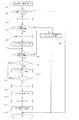
- FIG. 1 is a flowchart for explaining the flow of processing in the method for detecting the state of an electricity storage device of this embodiment
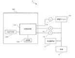
- FIG. 2 is a block diagram showing the configuration of the state detection device for the electricity storage device of this embodiment.
- a state detection device 100 detects the state of an electricity storage device (storage battery) 10 mounted in the target system 1.
- the storage battery 10 is an electricity storage device that contains an electrolytic solution or a solid electrolyte therein and can store electrical energy due to a state change accompanied by movement of ions.
- the target system 1 includes charging / discharging means 11 for charging / discharging the storage battery 10, voltage measuring means 12 for measuring the voltage of the storage battery 10, and current measuring means 13 for measuring the current of the storage battery 10.
- the measurement values measured by the voltage measuring unit 12 and the current measuring unit 13 are input to the state detection device 100 and used for state detection.
- the temperature measurement unit 14 may be connected to the storage battery 10 and the temperature measurement value measured by the temperature measurement unit 14 may be input to the state detection device 100 and used for state detection.
- the state detection device 100 connected to the target system 1 includes a state detection unit 110, a storage unit 120, and an input / output unit 130.
- the state detection unit 110 receives the voltage measurement value and the current measurement value of the storage battery 10 from the voltage measurement unit 12 and the current measurement unit 13, respectively, and performs the process according to the state detection method of the present embodiment to detect the state of the storage battery 10.
- the temperature measuring means 14 may be connected to the storage battery 10 and a temperature measurement value may be input to the state detection unit 110 to be used for detecting the state of the storage battery 10.
- the storage unit 120 is used to store various reference data and measurement data necessary for the state detection process.
- the input / output means 130 is means for notifying a user or the like of a state detection result or the like.
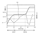
- FIG. 3 shows an example of a change in the stable OCV with respect to the SOC of the storage battery 10.
- the stable OCV indicated by reference numeral 21 changes relatively greatly with respect to the change in SOC when the SOC is less than SOC1 or greater than SOC2. Therefore, when the SOC is within this range, the SOC can be accurately obtained from the stable OCV using the relationship of the stable OCV to the SOC.
- the SOC is SOC1 or more and SOC2 or less (hereinafter, the SOC during this period is referred to as intermediate SOC)
- the stable OCV indicated by reference numeral 21 slightly changes with respect to the change in SOC. Therefore, it is extremely difficult to accurately obtain the SOC from the stable OCV using the stable OCV to SOC relationship.
- the state detection device 100 performs state detection using the OCV measured by the voltage measuring unit 30, whether or not the relationship of the stable OCV to SOC can be used is determined by the above-described SOC1 and SOC1. This is performed using OCV1 and OCV2, which are stable OCVs corresponding to the respective SOCs, instead of the SOC2. That is, when the stable OCV is less than OCV1 or greater than OCV2, the SOC is calculated from the stable OCV using the relationship of the stable OCV to SOC.
- the integrated value of the OCV in the predetermined period after the end of charge / discharge or the change in the OCV from the predetermined reference OCV is integrated.
- An OCV change integration value can be used.
- the OCV integral value or the OCV change integral value will be referred to as a relaxation amount, and it will be described that the SOC can be calculated using this relaxation amount.
- the amount of relaxation changes depending on the charge / discharge history of the storage battery 10.
- the relaxation amount represents the amount of movement of the electrolyte present in the electricity storage device.
- the ion concentration of the electrolytic solution changes, so that the moving speed of the electrolytic solution changes and the relaxation amount changes.
- the state of the electrode plate or active material of the electricity storage device changes and the electrode plate lattice expands or irreversible precipitates are formed on the surface of the electrode plate, the movement and reaction rate of the electrolyte change and the amount of relaxation increases. Appears as a change.
- the change in the amount of movement of the electrolytic solution inside the electricity storage device can be known using the relaxation amount.
- the OCV change integration value (DSt1_t2) in the period t1 to t2 is calculated by the following equation (2).
- ⁇ t t2 ⁇ t1.
- FIG. 22 An example of the change in the relaxation amount with respect to the SOC is indicated by reference numeral 22 in FIG.
- the SOC change of the OCV change integration value DSt1_t2 calculated by the equation (2) is shown, but the same tendency can be obtained by using the OCV integration value St1_t2.
- the stable OCV21 hardly changes, whereas the relaxation amount 22 increases monotonously with respect to the intermediate SOC. It shows a tendency to. Therefore, the relationship between the relaxation amount and the SOC as indicated by reference numeral 22 in FIG. 3 is obtained in advance and stored in the storage unit 120, and the relationship between the relaxation amount and the SOC is used when the stable OCV is OCV1 or more and OCV2 or less.
- the SOC can be calculated.
- FIG. 3 shows an example of the change in the relaxation amount with respect to the SOC.
- Such a relationship between the relaxation amount and the SOC is obtained when the storage battery performs only one of charging and discharging before stopping charging and discharging. .
- FIGS. 4 is a graph in which the horizontal axis represents time and the vertical axis represents the voltage of the storage battery.
- FIG. 5 is a graph in which the horizontal axis represents SOC and the vertical axis represents the amount of relaxation.
- FIG. 4 (a) the SOC at time t1 is fully charged, 10% discharge is performed from time t1 to time t2, and then the discharge is stopped for 1 hour from time t2 to time t3. The internal state is relaxed. Thereafter, 5% charge is performed from time t3 to time t4, charging for 1 hour from time t4 to time t5 is stopped, and the internal state of the storage battery is relaxed again. Further, 5% discharge is performed between time t5 and time t6, and the discharge for one hour from time t6 to time t7 is stopped to relax the internal state of the storage battery. Thus, in the example of Fig.4 (a), it charges in the middle of discharge.
- the SOC at time t11 is set to 20%, 10% charging is performed from time t11 to time t2, and then charging for one hour from time t12 to time t13 is stopped.
- This relaxes the internal state of the storage battery.
- 5% discharge is performed from time t13 to time t14, and the discharge for one hour from time t14 to time t15 is stopped to relax the internal state of the storage battery again.
- 5% charge is performed from time t15 to time t16, and charging for one hour from time t16 to time t17 is stopped to relax the internal state of the storage battery.
- FIG.4 (b) it discharges in the middle of charge.
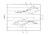
- FIG. 5 shows a change in relaxation amount with respect to the SOC when charging and discharging are mixed as shown in FIG.
- the SOC at time t1 before the start of charging / discharging is fully charged and the SOC at time t11 is 20%, but the SOC at times t1 and t11 is further changed to the SOC on the horizontal axis shown in FIG.
- the change of the relaxation amount when charging is performed in the middle of the discharge shown in FIG. 4A is indicated by reference numerals 31 to 33, and the discharge is performed in the middle of the charging shown in FIG. 4B.
- the change in the amount of relaxation at that time is indicated by reference numerals 34 to 36.
- the relaxation amount calculated during relaxation from time t2 to t3 after 10% discharge is monotonous with respect to the intermediate SOC as indicated by reference numeral 31. Has increased.
- the relaxation amount calculated during the relaxation from time t4 to t5 after 5% charge after 10% discharge has a small change with respect to the intermediate SOC as indicated by reference numeral 32.
- the relaxation amount calculated during relaxation from time t6 to t7 after performing 5% discharge after 10% discharge and 5% charge is increased monotonously again with respect to the intermediate SOC as indicated by reference numeral 33. It has become.
- the same tendency as described above is observed even in the change in the relaxation amount corresponding to the charge / discharge in FIG. That is, the relaxation amount calculated during relaxation from time t12 to time t13 after 10% charging monotonously increases with respect to the intermediate SOC as indicated by reference numeral 34. On the other hand, the relaxation amount calculated during the relaxation from time t14 to t15 after 5% discharge after 10% charge hardly changes with respect to the intermediate SOC as indicated by reference numeral 35. Further, the relaxation amount calculated during relaxation from time t16 to t17 after 5% charge after 10% charge and 5% discharge is increased monotonously again with respect to the intermediate SOC as indicated by reference numeral 36. It has become.
- the state detection method for the power storage device of the present embodiment provides a method for detecting the charge / discharge history before the charge / discharge stop.
- FIG. 6 is a graph showing an example of charge / discharge control by the state detection method of the electricity storage device of the present embodiment.
- a probe pulse 40 having a predetermined capacity is applied to the storage battery 10 in order to determine the previous charging / discharging history.
- the OCV change integration value DSt1_t2 is calculated using Equation (2) during the period from time tb to tc after application of the probe pulse.
- the probe pulse 40 can be set in advance according to the type of the storage battery 10. For example, in the case of an iron phosphate Li-ion battery, the charge is preferably 0.5%.
- the length of the relaxation period tb to tc after application of the probe pulse is preferably about 30 minutes.
- FIG. 7 shows an example of the time change of the voltage drop when the probe pulse 40 is charged at 0.5%.
- the horizontal axis represents the elapsed time after application of the probe pulse
- the vertical axis represents the amount of voltage drop.
- the respective probes when the probe pulse is applied with the same SOC when applying the probe pulse and when the probe pulse is applied with the charge history and when the probe pulse is applied with the discharge history are shown.
- Changes in the voltage drop after applying the pulse are indicated by reference numerals 41 and 42, respectively. Both voltage drop amounts 41 and 42 indicate changes for 30 minutes after the application of the probe pulse 40 is completed.
- the voltage drop 41 when the probe pulse is applied in a state having a charging history always converges to 0 at a value that is always higher than the voltage drop 42 when a probe pulse is applied in a state having a discharge history. I can see it going. Even when the SOC is different, the voltage drop amount when the probe pulse is applied in a state having a charge history changes in a region higher than the boundary line 43 shown in FIG. 7, and the voltage drop when the probe pulse is applied in a state having a discharge history. It was revealed that the voltage drop amount changes in a region lower than the boundary line 44.
- the integrated value of the voltage drop amount after applying the probe pulse that is, the OCV change integrated value DS becomes larger than a predetermined value (assumed to be the first threshold Th1) when having a charge history, and the discharge history. Is smaller than another predetermined value (referred to as the second threshold Th2). Therefore, the relaxation amount DS is calculated after applying the probe pulse, and based on this, the charge / discharge history of the storage battery 10 can be determined as follows. That is, DS> Th1 (3) Is determined to have a charge history, DS ⁇ Th2 (4) Is determined to have a discharge history.
- the relaxation amount DS is used as the history determination state quantity for determining the charge / discharge history.
- the OCV integration value S may be used as the history determination state quantity instead of the OCV change integration value DS.
- the charge / discharge history can be determined using the voltage drop amount itself instead of the relaxation amount DS.
- the charge / discharge history may be determined using the voltage drop amount instead of the relaxation amount DS.
- the relaxation amount DS in the equations (3) and (4) used for the determination of the charge / discharge history is not limited to the integrated value of the OCV change amount in one period after application of the probe pulse.
- the relaxation period after application of the probe pulse May be divided into two or more periods, and the OCV change integration value DS may be calculated in each period.
- a more detailed charge / discharge history amount It is also possible to determine (the amount of charge or discharge). This determination can be similarly performed by using the OCV integrated value S or the voltage drop amount instead of the OCV change integrated value DS.
- step S1 when the state detection unit 110 inputs a signal requesting charge / discharge history determination from the input / output unit 130 in step S1, it is determined whether or not the storage battery 10 can be disconnected from the load 2 in step S2. In this determination, for example, when permission to disconnect the storage battery 10 is given in advance from the target system 1 or a user of the target system 1, it is determined that disconnection is possible.
- step S2 If it is determined in step S2 that the storage battery 10 cannot be disconnected, the charge / discharge history determination process is terminated. On the other hand, if it is determined in step S2 that the storage battery 10 can be disconnected, the storage battery 10 is disconnected from the load 2 in step S3. In the next step S4, a current measurement value is input from the current measurement means 13 and compared with a predetermined stop current threshold value. When the current measurement value is equal to or less than the stop current threshold value, it is determined that charging / discharging is stopped.
- the determination of charge / discharge stop need not be limited to only when the measured current value is 0. For example, charge / discharge is also performed when a minute current (dark current) is consumed by a measuring instrument, controller, communication device, etc. You may make it determine with a stop.
- step S4 If the measured current value is larger than the stop-time current threshold value in step S4, for example, “charge / discharge history determination error” or the like is output to the input / output means 130 in step S5, and the process is terminated.
- the charging / discharging means 11 is connected to the storage battery 10 in step S6, and a preset current integrated value of a predetermined capacity, that is, a probe pulse is applied to the storage battery 10.
- step S7 the charging / discharging means 11 is disconnected from the storage battery 10, and the time t at this time is stored as tb. Time tb corresponds to tb shown in FIG.
- step S8 the current measurement value is input from the current measurement means 13 and compared with the stop current threshold value. When the current measurement value is equal to or less than the stop current threshold value, it is determined that charging / discharging is stopped, and the process proceeds to step S9. On the other hand, when the measured current value is larger than the stop-time current threshold value, the process proceeds to step S5, where a “charge / discharge history determination error” or the like is output to the input / output unit 130, and the process ends.
- step S9 it is determined whether the time t has reached a predetermined time interval ts1 to ts2 (ts1 ⁇ ts2), that is, whether the time t is after the time ts1, and when it is determined that the time t is after the time ts1. Advances to step S10. On the other hand, when it is determined that the time ts1 has not been reached, the process returns to step S8 again after a predetermined time interval (state detection cycle).
- the time interval ts1 to ts2 is included in the period from time tb to tc shown in FIG.
- step S10 it adds the multiplied by the time interval OCV measurement OCV_now (t) based on equation (1) to the OCV integral value S ts1 _ ts2.
- step S11 it is determined whether or not the time t has reached the end of the time interval ts1 to ts2, and when the time t has not reached ts2, the process returns to step S8 again after a predetermined time interval. On the other hand, when the time t has reached ts2, the process proceeds to step S12.
- step S13 the OCV change integration value DS ts1 — ts2 is calculated based on the equation (2) from S ts1 — ts2 calculated in step S10 and the OCV_base stored in step S12.
- step S14 the charge / discharge history determination values Th1 and Th2 previously stored in the storage unit 120 are read, and the charge / discharge history of the storage battery 10 is determined based on the equations (3) and (4). The determination result of the charge / discharge history is output to the outside from the input / output unit 130 in step S15.
- FIG. 8 is a flowchart for explaining the flow of processing in the method of detecting the state of the electricity storage device of this embodiment.
- the SOC of the storage battery 10 can be calculated with high accuracy based on the charge / discharge history determination result determined by the storage device state detection method of the first embodiment. is there.
- step S21 determines whether the charge / discharge history is discharged or charged. As a result, if it is determined that it is a discharge history, the process proceeds to step S22, whereas if it is determined that it is a charge history, the process proceeds to step S23. Since the probe pulse applied to the storage battery 10 in step S6 is charging with a predetermined capacity, when it is determined that the discharge history is in step S21, charging is performed by applying the probe pulse after discharging. As a result, it can be seen that the internal state of the storage battery 10 is a state in which the influence of discharging and the influence of charging are mixed.
- step S22 a predetermined capacity of discharge is performed in step S22 (hereinafter referred to as discharge before state detection).
- discharge before state detection a predetermined capacity of discharge is performed in step S22 (hereinafter referred to as discharge before state detection).
- the same discharging, charging, and discharging as the charging / discharging history shown in FIG. 4A are sequentially performed, and the change in the intermediate SOC is changed in the same manner as the relaxation amount indicated by reference numeral 33 in FIG.
- a relaxation amount that changes monotonously can be obtained.
- step S6 the case where the probe pulse applied in step S6 is charging with a predetermined capacity will be described. However, if the probe pulse is discharging with a predetermined capacity, it is determined in step S21 that the charge / discharge history is charging. When it is determined, the process proceeds to step S22, and when it is determined that the discharge is performed, the process proceeds to step S23. In this case, charging of a predetermined capacity (charging before state detection) is performed in step S22.
- the discharge amount (or charge amount) performed as the discharge before the state detection (or the charge before the state detection) is the number of combinations of the storage battery 10 in the case where the type, model number, capacity, and a plurality of cells are combined. It determines suitably according to it. As an example, in the case of a 18650 type iron phosphate Li-ion battery, it is desirable to perform discharge of 2% or more in terms of new capacity as discharge before state detection.
- the absolute value of the charge capacity (discharge capacity) applied by the probe pulse should be smaller than the absolute value of the discharge capacity (charge capacity) discharged (charged) by the discharge before the state detection (charge before the state detection). .
- the influence of the charge history (discharge history) due to the application of the probe pulse can be significantly reduced by the subsequent discharge before state detection (charge before state detection), which is the middle when only discharging (charging) is performed. It becomes possible to approximate the relationship between the SOC and the relaxation amount.
- step S23 it is determined whether OCV_base substantially equal to the stable OCV is greater than or equal to OCV1 and less than or equal to OCV2.
- OCV_base is greater than or equal to OCV1 and less than or equal to OCV2
- the process proceeds to step S24, whereas when OCV_base is less than OCV1 or greater than OCV2, the process proceeds to step S26.
- step S24 the relaxation amount is calculated based on the formula (1) or the formula (2).
- the OCV integral value St1_t2 calculated from the equation (1) is used as the relaxation amount
- the OCV integral value St1_t2 is calculated by performing the same processing as steps S8 to S11 during the predetermined relaxation period.
- the OCV change integration value DSt1_t2 calculated from the expression (2) is used as the relaxation amount
- the OCV change integration value DSt1_t2 is calculated by performing the same processing as steps S8 to S13 during the predetermined relaxation period.
- the SOC of the storage battery 10 is calculated from the relationship between the relaxation amount and the SOC using the relaxation amount calculated in step S23.
- the relationship between the relaxation amount and the SOC can be created based on the relationship of the change in the relaxation amount with respect to the intermediate SOC as indicated by reference numeral 33 in FIG. 5 in advance.
- the relationship between the relaxation amount and the SOC created in advance is stored in the storage unit 120, and is read from the storage unit 120 and used for calculating the SOC in step S25.
- the process proceeds to step S27.
- step S26 the SOC is calculated from the relationship of the stable OCV to the SOC with OCV_base as the stable OCV.
- the relationship between the stable OCV and the SOC can be created based on the change in the stable OCV 21 with respect to the SOC shown in FIG. 3 obtained in advance.
- the stable OCV-SOC relationship created in advance is stored in the storage unit 120, and is read from the storage unit 120 and used for calculating the SOC in step S26.
- the process proceeds to the next step S27.
- step S27 the SOC calculated in step S26 or S27 is output from the input / output means 130 to the outside.
- the reference time for obtaining OCV_base is preferably a time that is 30 minutes or more after the end of the pre-state detection charge / discharge control. For example, in an iron phosphate Li-ion battery, it is preferably about 1 hour. The reference time varies depending on the size and type of the battery.
- FIG. 9 is a flowchart for explaining the flow of processing according to the state detection method for the power storage device of the present embodiment.
- step S22 discharge before state detection is performed in step S22 only when it is determined that the discharge history is determined in step S21.
- the state detection method of the power storage device of the present embodiment when it is determined that the discharge history is not determined in step S21, that is, the charge history is determined, charging before state detection is performed in step S31. Thereby, it becomes possible to calculate the SOC with higher accuracy by using the relationship between the relaxation amount and the SOC corresponding to the internal state of the storage battery after the charge is stopped.
- FIG. 10 is a block diagram showing an electricity storage device 10 ′ configured by combining a plurality of cells.
- the electricity storage device 10 ′ is configured by connecting in parallel six cells 10a to 10f and 10g to 10l connected in series. In this way, in the electricity storage device 10 ′ composed of a plurality of cells, it is not necessary to apply the probe pulse to all the cells in order to determine the charge / discharge history, but only to apply the probe pulse to some cells. Can be determined.
- FIG. 11 shows a flowchart for explaining the flow of processing by the method for detecting the state of the electricity storage device of the present embodiment.
- a cell to which a probe pulse is applied is selected in step S41.
- the process of steps S6 to S15 is performed on the selected cell to determine the charge / discharge history.
- discharge before state detection is performed in steps S21 and S22 as necessary.
- the processes in steps S23 to S27 are performed on all the cells by the processes in steps S42 and S43. Thereby, the SOC of all the cells can be calculated.
- the charge / discharge history of the power storage device can be determined with high accuracy.
- the operation of the system equipped with the power storage device can be facilitated, the system operation rate and safety can be improved, and the management cost can be reduced.
- target system 2 load 10: power storage device 11: charge / discharge means 12: voltage measurement means 13: current measurement means 14: temperature measurement means 100: state detection device 110: state detection unit 120: storage unit 130: input / output means
Landscapes
- Engineering & Computer Science (AREA)
- Manufacturing & Machinery (AREA)
- Chemical & Material Sciences (AREA)
- Chemical Kinetics & Catalysis (AREA)
- Electrochemistry (AREA)
- General Chemical & Material Sciences (AREA)
- Physics & Mathematics (AREA)
- General Physics & Mathematics (AREA)
- Secondary Cells (AREA)
- Tests Of Electric Status Of Batteries (AREA)
- Charge And Discharge Circuits For Batteries Or The Like (AREA)
Abstract
蓄電デバイスの充放電履歴を高精度に判定することができる蓄電デバイスの状態検知方法及び状態検知装置を提供する。 充放電停止後、ステップS6でプローブパルスを蓄電池10に印加し、ステップS9~S11でOCV測定値を時間積分してOCV積分値Sts1_ts2を算出する。ステップS12では、時刻tcにおけるOCVを測定してこれをOCV_baseとする。ステップS13では、Sts1_ts2とOCV_baseとからOCV変化積分値DSts1_ts2を算出する。ステップS14では、予め保存されている充放電履歴判定値Th1、Th2に基づいて蓄電池10の充放電履歴を判定する。
Description
本発明は、蓄電デバイスの状態検知方法及び状態検知装置に関し、特に蓄電デバイスの内部状態の変化を支配する充放電履歴を精度よく判定する蓄電デバイスの状態検知方法及び状態検知装置に関するものである。
近年、蓄電デバイスは多方面の分野で利用されるようになっており、容量や寸法、重量等も多種類のものが提供されている。小型小容量の蓄電デバイスとしては、携帯型の電動機器や情報端末等に利用されるものがあり、大型大容量の蓄電デバイスとしては、停電時のバックアップ用電源や電動フォークリフト等の電源に利用されるものがある。
携帯型情報機器の分野では、情報処理システムやアプリケーション、データ処理速度などの進歩に合わせて、ユーザが情報機器を2-3年程度で交換することが多く、情報機器の製品寿命が短くなっている。そのため、情報機器に搭載されている小型小容量の蓄電デバイスが寿命末期まで使用し続けられることは少なく、蓄電デバイスの管理としては使用中の残容量が表示されて管理できれば十分であり、劣化により満充電容量が新品時に比べてどの程度低下したかは大きな問題となっていない。
一方で、大型大容量の蓄電デバイスが利用される分野では、蓄電デバイスを搭載する装置の方が蓄電デバイスの寿命より長い期間にわたって使用されるため、蓄電デバイスのメンテナンスや交換等の管理が必要であった。従来、このような大型大容量の蓄電デバイスは、常に満充電かそれに近い状態に維持するように管理されており、蓄電デバイスの残容量を検出して管理する必要性はなかった。そのため、従来より知られているインピーダンス法を用いて蓄電デバイスの新品時からの劣化度を管理すればよかった。
また、最近の新たな用途として蓄電デバイスの利用が始まったハイブリッド自動車(HEV)や電気自動車(EV)の分野、さらには電力網における電力エネルギーマネージメントシステム(EMS)の分野では、システムの製品寿命が長いため、劣化に伴う満充電容量の新品時からの劣化度を管理する必要がある。それに加えて、このような新規の用途分野では、蓄電デバイスからの放電だけでなく蓄電デバイスへの充電も要求されるため、蓄電デバイスを常に充電も放電も可能な状態、すなわち残容量を適切な部分充電状態(PSOC)に維持するように管理することが要求されている。このように、HEV、EV、EMS等の蓄電デバイスの新規の用途分野では、蓄電デバイスの劣化度の管理と残容量の管理を両立させて行うことが要求される。
従来より、蓄電デバイスの残容量と電圧との関係がネルンストの式で定義されており、電圧を測定することで蓄電デバイスの性能を判断することができていた。例えば、特許文献1には、液式鉛蓄電池が充放電停止後十分に安定したときの開放端電圧(OCV:Open Circuit Voltage)と残容量(SOC:State of charge)との間に図12に示すような1:1に対応する関係があることが記載されており、このような安定時のOCVとSOCとの関係を用いて蓄電デバイスの状態検知を行う技術が記載されている。
しかしながら、蓄電デバイスの種類によっては、SOCが変化しているにもかかわらず安定時OCVがほとんど変化しないものがある。一例として、燐酸鉄系Liイオン電池におけるSOCと安定時OCVとの関係を図13に示す。同図において、SOCがSOC_1~SOC_2[%]の範囲では安定時OCVの変化が非常に小さくなっている。ここで、SOC_1、SOC_2はそれぞれ、例えば40%、75%程度であり、35%程度の比較的大きなSOCの範囲で安定時OCVの変化が小さい。そのため、SOCがSOC_1~SOC_2の範囲にあるときは、安定時OCVを測定してSOCを求めようとしても十分な精度でSOCを得るのが難しいといった問題がある。
そこで、SOCの変化に対して安定時OCVがほとんど変化しない場合には、安定時OCVに代えて、蓄電デバイスの充放電履歴に基づいて内部状態の変化をより適格に示すことができる状態量を求め、この状態量を用いてSOCを算出するようにするのがよい。しかしながら、蓄電デバイスが充電履歴を有しているか、あるいは放電履歴を有しているか、といった充放電履歴を判定する方法はこれまで知られておらず、従来は充放電履歴に依存しない方法で蓄電デバイスの状態検知を行っていた。そのため、充放電履歴によっては十分な精度でSOCを求めることができなかった。
そこで、本発明はこれらの問題を解決するためになされたものであり、蓄電デバイスの充放電履歴を高精度に判定することができる蓄電デバイスの状態検知方法及び状態検知装置を提供することを目的とする。
本発明の蓄電デバイスの状態検知方法の第1の態様は、充放電停止後に停止前の充放電履歴を判定する蓄電デバイスの状態検知方法であって、第1容量の充電または放電をプローブパルスとして前記蓄電デバイスに印加し、前記プローブパルス印加後の第1の期間に前記蓄電デバイスの開回路電圧(OCV)の測定値を取得し、前記OCV測定値から所定の履歴判定用状態量を算出し、前記履歴判定用状態量と事前に作成された参照データとから前記充放電履歴が充電履歴あるいは放電履歴であると判定することを特徴とする。
本発明の蓄電デバイスの状態検知方法の他の態様は、前記履歴判定用状態量は、前記プローブパルス印加後の第1の期間にわたって前記OCV測定値を時間積分して算出したOCV積分値であり、前記参照データは、前記OCV積分値に対する閾値であり、前記OCV積分値を前記参照データと比較することで前記充放電履歴が充電履歴あるいは放電履歴であると判定することを特徴とする。
本発明の蓄電デバイスの状態検知方法の他の態様は、前記履歴判定用状態量は、前記OCV測定値の所定の基準OCVからの変化量を時間積分したOCV変化積分値であり、前記参照データは、前記OCV変化積分値に対する閾値であり、前記プローブパルス印加後の前記第1の期間が経過したときの前記OCV測定値を取得して前記基準OCVとし、前記OCV測定値を時間積分したOCV積分値から前記基準OCVに前記第1の期間の時間長を乗じた値を減算して前記OCV変化積分値を算出し、前記OCV変化積分値を前記参照データと比較することで前記充放電履歴が充電履歴あるいは放電履歴であると判定することを特徴とする。
本発明の蓄電デバイスの状態検知方法の他の態様は、前記参照データとして所定の第1閾値及び該第1閾値より大きい第2の閾値を予め設定しておき、前記OCV積分値または前記OCV変化積分値が前記第1閾値より小さいときに前記充放電履歴を放電履歴と判定する一方、前記OCV積分値または前記OCV変化積分値が前記第2の閾値より大きいときに前記充放電履歴を充電履歴と判定することを特徴とする。
本発明の蓄電デバイスの状態検知方法の他の態様は、前記履歴判定用状態量は、前記OCV測定値と所定の基準OCVとの差である電圧降下量であり、前記参照データは、電圧降下量の時間変化を表す関数または表であり、前記電圧降下量を前記充放電停止からの経過時間に対応する前記参照データと比較し、前記電圧降下量が前記参照データより小さいときに前記充放電履歴を放電履歴と判定する一方、前記電圧降下量が前記参照データより大きいときに前記充放電履歴を充電履歴と判定することを特徴とする。
本発明の蓄電デバイスの状態検知方法の他の態様は、前記第1容量の充電または放電は、前記蓄電デバイスの新品換算容量の5%以下であることを特徴とする。
本発明の蓄電デバイスの状態検知方法の他の態様は、前記蓄電デバイスの電流測定値が所定の停止時電流閾値以下のときを前記充放電停止と判定することを特徴とする。
本発明の蓄電デバイスの状態検知方法の他の態様は、前記プローブパルスが前記第1容量の充電でかつ前記充放電履歴が充電履歴のとき、あるいは前記プローブパルスが前記第1容量の放電でかつ前記充放電履歴が放電履歴のときには、予め設定された残容量(SOC)算出式を用いて前記OCV積分値または前記OCV変化積分値あるいは前記基準OCVから前記蓄電デバイスのSOCを算出することを特徴とする。
本発明の蓄電デバイスの状態検知方法の他の態様は、前記充放電履歴が充電履歴かあるいは放電履歴かによってそれぞれ第2容量の充電あるいは放電を前記蓄電デバイスに印加し、前記第2容量の充電あるいは放電を印加後に前記OCV積分値または前記OCV変化積分値と前記基準OCVとを求め、予め設定されたSOC算出式を用いて前記OCV積分値または前記OCV変化積分値あるいは前記基準OCVから前記蓄電デバイスのSOCを算出することを特徴とする。
本発明の蓄電デバイスの状態検知方法の他の態様は、前記充放電履歴が充電履歴で前記プローブパルスが前記第1容量の放電のときには第2容量の充電を前記蓄電デバイスに印加し、あるいは前記充放電履歴が放電履歴で前記プローブパルスが前記第1容量の充電のときには前記第2容量の放電を前記蓄電デバイスに印加し、前記第2容量の充電あるいは放電を印加後に前記OCV積分値または前記OCV変化積分値と前記基準OCVとを求め、予め設定されたSOC算出式を用いて前記OCV積分値または前記OCV変化積分値あるいは前記基準OCVから前記蓄電デバイスのSOCを算出することを特徴とする。
本発明の蓄電デバイスの状態検知方法の他の態様は、前記充放電履歴が充電履歴で前記プローブパルスが前記第1容量の充電のときには第2容量の充電を前記蓄電デバイスに印加し、前記第2容量の充電を印加後に前記OCV積分値または前記OCV変化積分値と前記基準OCVとを求め、予め設定されたSOC算出式を用いて前記OCV積分値または前記OCV変化積分値あるいは前記基準OCVから前記蓄電デバイスのSOCを算出することを特徴とする。
本発明の蓄電デバイスの状態検知方法の他の態様は、前記第2容量は、前記第1容量より大きいことを特徴とする。
本発明の蓄電デバイスの状態検知方法の他の態様は、前記蓄電デバイスは、複数のセルを直列または並列に接続して構成されており、前記プローブパルスを前記複数のセルの少なくとも1つに印加して前記充放電履歴を判定し、前記第2容量の充電あるいは放電を前記複数のセルすべてに印加してそれぞれのSOCを算出することを特徴とする。
本発明の蓄電デバイスの状態検知方法の他の態様は、前記SOC算出式は、OCV積分値またはOCV変化積分値対SOCの関係式、あるいは基準OCV対SOCの関係式であり、前記基準OCVが所定の範囲にあるときは、前記OCV積分値またはOCV変化積分値対SOCの関係式を用いて前記OCV積分値または前記OCV変化積分値から前記SOCを算出し、前記基準OCVが前記所定の範囲外にあるときは、前記基準OCV対SOCの関係式を用いて前記基準OCVから前記SOCを算出することを特徴とする。
本発明の蓄電デバイスの状態検知装置の第1の態様は、充放電手段を用いて充放電可能な蓄電デバイスの充放電停止後に停止前の充放電履歴を判定する蓄電デバイスの状態検知装置であって、記憶部と、プローブパルスとして第1容量の充電または放電を前記蓄電デバイスに印加するように前記充放電手段を制御し、前記プローブパルス印加後の第1の期間に前記蓄電デバイスの開回路電圧(OCV)の測定値を取得し、前記プローブパルス印加後の第1の時間が経過したときの前記OCV測定値を取得して基準OCVとし、前記第1の期間にわたって前記OCV測定値を時間積分したOCV積分値から前記基準OCVに前記第1の期間の時間長を乗じた値を減算してOCV変化積分値を算出し、前記OCV変化積分値を所定の閾値と比較することで前記充放電履歴が充電履歴あるいは放電履歴であると判定する状態検知部と、前記状態検知部から前記充放電履歴の判定結果を入力して外部に出力する入出力手段と、を備えることを特徴とする。
本発明によれば、蓄電デバイスの充放電履歴を高精度に判定することができる蓄電デバイスの状態検知方法及び状態検知装置を提供することが可能となる。
本発明の好ましい実施の形態における蓄電デバイスの状態検知方法及び状態検知装置について、図面を参照して詳細に説明する。なお、同一機能を有する各構成部については、図示及び説明簡略化のため、同一符号を付して示す。
本発明によれば、蓄電デバイスの充放電履歴を高精度に判定することができる蓄電デバイスの状態検知方法及び状態検知装置を提供することができる。また、SOCの変化に対する安定時OCVの変化が小さいために安定時OCVからSOCを精度よく求めるのが難しい蓄電デバイスに対し、蓄電デバイスの充放電履歴に基づいてSOCを高精度に算出することができる状態検知方法及び状態検知装置を提供する。SOCの変化に対して安定時OCVの変化が小さくなる蓄電デバイスとして、以下では燐酸鉄系Liイオン電池を例に説明する。但し、以下で説明する内容は、燐酸鉄系Liイオン電池に限定されず、別の蓄電デバイスにも同様に適用できるものである。
(第1実施形態)
本発明の第1の実施形態に係る蓄電デバイスの蓄電デバイスの状態検知方法及び状態検知装置を、図1、2を用いて説明する。図1は、本実施形態の蓄電デバイスの状態検知方法における処理の流れを説明するためのフローチャートであり、図2は、本実施形態の蓄電デバイスの状態検知装置の構成を示すブロック図である。
本発明の第1の実施形態に係る蓄電デバイスの蓄電デバイスの状態検知方法及び状態検知装置を、図1、2を用いて説明する。図1は、本実施形態の蓄電デバイスの状態検知方法における処理の流れを説明するためのフローチャートであり、図2は、本実施形態の蓄電デバイスの状態検知装置の構成を示すブロック図である。
図2に示す本実施形態の状態検知装置100は、対象システム1に搭載された蓄電デバイス(蓄電池)10の状態検知を行うものである。蓄電池10は、内部に電解液または固体電解質を含有してイオンの移動を伴う状態変化により電気的なエネルギーを蓄積することができる蓄電デバイスである。
対象システム1は、蓄電池10を充放電するための充放電手段11と、蓄電池10の電圧を測定する電圧測定手段12と、蓄電池10の電流を測定する電流測定手段13とを備えている。電圧測定手段12及び電流測定手段13で測定された測定値は、状態検知装置100に入力されて状態検知に使用される。また、必要に応じて温度測定手段14を蓄電池10に接続し、温度測定手段14で測定された温度測定値も状態検知装置100に入力して状態検知に用いるようにしてもよい。
対象システム1に接続された状態検知装置100は、状態検知部110と、記憶部120と、入出力手段130とを備えている。状態検知部110は、電圧測定手段12及び電流測定手段13からそれぞれ蓄電池10の電圧測定値及び電流測定値を入力し、本実施形態の状態検知方法による処理を行って蓄電池10の状態検知を行う。また、蓄電池10に温度測定手段14を接続し、これから状態検知部110に温度測定値を入力して蓄電池10の状態検知に用いるようにしてもよい。記憶部120は、状態検知の処理に必要な各種参照データや測定データ等を保存するのに用いる。さらに入出力手段130は、状態検知結果等を使用者等に通知する手段である。
蓄電池10のSOCに対する安定時OCVの変化の一例を図3に示す。符号21で示す安定時OCVは、SOCがSOC1未満あるいはSOC2より大きいときは、SOCの変化に対して比較的大きく変化する。従って、SOCがこの範囲にあるときは、安定時OCV対SOCの関係を用いて安定時OCVからSOCを精度よく求めることができる。これに対し、SOCがSOC1以上SOC2以下(以下ではこの間のSOCを中間SOCと称する)のときは、SOCの変化に対して符号21で示す安定時OCVがわずかしか変化しない。そのため、安定時OCV対SOCの関係を用いて安定時OCVからSOCを精度よく求めることは極めて難しい。
なお、状態検知装置100では、電圧測定手段30で測定されたOCVを用いて状態検知を行うことから、安定時OCV対SOCの関係を用いることができるか否かの判断は、上記のSOC1及びSOC2でなくそれぞれに対応する安定時OCVであるOCV1及びOCV2を用いて行う。すなわち、安定時OCVがOCV1未満あるいはOCV2より大きいときに、安定時OCV対SOCの関係を用いて安定時OCVからSOCを求める処理を行う。
充放電終了後の緩和途中における内部状態の変化をより適格に表すことができる状態量として、充放電終了後の所定期間におけるOCV積分値、または所定の基準OCVからのOCVの変化量を積算したOCV変化積分値を用いることができる。以下では、OCV積分値またはOCV変化積分値を緩和量と称することとし、この緩和量を用いてSOCを算出することができることを説明する。また、この緩和量は蓄電池10の充放電履歴に依存して変化することを説明する。
緩和量は、蓄電デバイスの内部に存在する電解液の移動量を表すものである。蓄電デバイスの残存容量が変わると電解液のイオン濃度が変化するため、電解液の移動速度が変化して緩和量が変化する。また、蓄電デバイスの極板や活物質の状態が変化して極板格子が膨張したり極板表面に不可逆性の析出物が生じると、電解液の移動や反応速度が変化して緩和量の変化として現れる。このように、緩和量を用いて蓄電デバイス内部の電解液の移動量の変化を知ることができる。
緩和量に用いるOCV積分値またはOCV変化積分値の算出方法を以下に説明する。時刻をtで表し、時刻tにおける蓄電池10のOCV測定値をOCV_now(t)とするとき、時刻tがt1からt2の期間におけるOCV積分値(St1_t2とする)は、下記の式(1)を用いて算出される。

また、所定の基準OCVをOCV_baseとしたとき、期間t1~t2におけるOCV変化積分値(DSt1_t2とする)は下記の式(2)で算出される。
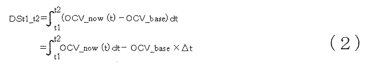 ここで、Δt=t2-t1である。
SOCに対する緩和量の変化の一例を図3の符号22に示す。ここでは、一例として式(2)で算出されるOCV変化積分値DSt1_t2のSOCの変化を示しているが、OCV積分値St1_t2を用いても同様の傾向が得られる。同図に示すように、SOCがSOC1以上SOC2以下(安定時OCVがOCV1以上OCV2以下)の中間SOCでは安定時OCV21がほとんど変化しないのに対し、緩和量22は中間SOCに対して単調に増加する傾向を示している。そこで、図3の符号22で示すような緩和量対SOCの関係を事前に求めて記憶部120に記憶させておき、安定時OCVがOCV1以上OCV2以下のときに緩和量対SOCの関係を用いてSOCを算出することができる。
SOCに対する緩和量の変化の一例を図3に示したが、このような緩和量対SOCの関係は、蓄電池が充放電停止前に充電または放電のいずれか一方だけを行っていたときに得られる。これに対し、充放電停止前に充電と放電とを混在させて行っていたときには、SOCに対する緩和量の変化が小さくなることが明らかとなった。充電と放電とを混在させたときのSOCに対する緩和量の変化の一例を、図4、5を用いて説明する。図4は、横軸を時間として縦軸に蓄電池の電圧を示したグラフである。また図5は、横軸をSOCとし縦軸に緩和量を示したグラフである。
図4(a)では、時刻t1におけるSOCを満充電とし、時刻t1から時刻t2までの間に10%の放電を行った後、時刻t2から時刻t3までの1時間放電を停止して蓄電池の内部状態を緩和させている。その後、時刻t3から時刻t4までの間に5%の充電を行い、時刻t4から時刻t5までの1時間充電を停止して再び蓄電池の内部状態を緩和させている。さらに、時刻t5から時刻t6までの間に5%の放電を行い、時刻t6から時刻t7までの1時間放電を停止して蓄電池の内部状態を緩和させている。このように、図4(a)の例では放電の途中に充電を行っている。
これに対し図4(b)では、時刻t11におけるSOCを20%とし、時刻t11から時刻t2までの間に10%の充電を行った後、時刻t12から時刻t13までの1時間充電を停止して蓄電池の内部状態を緩和させている。その後、時刻t13から時刻t14までの間に5%の放電を行い、時刻t14から時刻t15までの1時間放電を停止して再び蓄電池の内部状態を緩和させている。さらに、時刻t15から時刻t16までの間に5%の充電を行い、時刻t16から時刻t17までの1時間充電を停止して蓄電池の内部状態を緩和させている。このように、図4(b)の例では充電の途中に放電を行っている。
図4に示すような充電と放電とを混在させたときのSOCに対する緩和量の変化を図5に示す。図4では、充放電開始前の時刻t1におけるSOCを満充電とし時刻t11におけるSOCを20%としたが、時刻t1及びt11におけるSOCをさらに変化させて図5に示す横軸のSOCとしている。図5では、図4(a)に示した放電の途中に充電を行ったときの緩和量の変化を符号31~33で示し、図4(b)に示した充電の途中に放電を行ったときの緩和量の変化を符号34~36で示している。
まず、図4(a)の充放電に対応した緩和量の変化では、10%放電後の時刻t2~t3の緩和中に算出した緩和量が、符号31で示すように中間SOCに対して単調に増加している。これに対し、10%放電後に5%充電を行った後の時刻t4~t5の緩和中に算出した緩和量は、符号32で示すように中間SOCに対する変化が小さくなっている。さらに、10%放電及び5%充電後に5%放電を行った後の時刻t6~t7の緩和中に算出した緩和量は、符号33で示すように中間SOCに対して再び単調に増加するようになっている。
一方、図4(b)の充放電に対応した緩和量の変化でも、上記と同様の傾向がみられる。すなわち、10%充電後の時刻t12~t13の緩和中に算出した緩和量は、符号34で示すように中間SOCに対して単調に増加している。これに対し、10%充電後に5%放電を行った後の時刻t14~t15の緩和中に算出した緩和量は、符号35で示すように中間SOCに対してほとんど変化していない。さらに、10%充電及び5%放電後に5%充電を行った後の時刻t16~t17の緩和中に算出した緩和量は、符号36で示すように中間SOCに対して再び単調に増加するようになっている。
図4,5を用いて説明したように、放電後に充電を行う、あるいは充電後に放電を行うと、その後の緩和中に算出した緩和量は、中間SOCに対する変化が小さくなることが明らかとなった。すなわち、中間SOCに対する緩和量の変化は、それまでの充放電の履歴に依存することがわかった。このように、充放電停止中の蓄電池の電解液分布に充電の影響と放電の影響が混在して残っているときは、電解液の移動量を表す緩和量にも充電の影響と放電の影響が残ってしまう。そのため、充放電履歴によっては、緩和量からSOCを適切に推定することができなくなるおそれがある。そこで、本実施形態の蓄電デバイスの状態検知方法では、充放電停止前の充放電履歴を検知する方法を提供する。
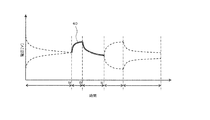
本実施形態の蓄電デバイスの状態検知方法を、図6を用いて説明する。図6は、本実施形態の蓄電デバイスの状態検知方法による充放電制御の一例を示すグラフである。本実施形態の状態検知方法では、充放電停止中の時刻taにおいて、それ以前の充放電履歴を判定するために所定容量のプローブパルス40を蓄電池10に印加する。そして、プローブパルス印加後の時刻tb~tcの期間に、式(2)を用いてOCV変化積分値DSt1_t2を算出する。プローブパルス40は、蓄電池10の種類に応じて事前に設定しておくことができ、例えば燐酸鉄系Liイオン電池では0.5%の充電とするのがよい。また、プローブパルス印加後の緩和期間tb~tcの時間長を30分程度とするのがよい。
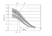
上記のプローブパルス40として0.5%の充電を行ったときの電圧降下量の時間変化の一例を図7に示す。図7では、横軸をプローブパルス印加後の経過時間とし、縦軸を電圧降下量としている。電圧降下量の変化の一例として、プローブパルスを印加するときのSOCを同じとし、充電履歴を有する状態でプローブパルスを印加したときと放電履歴を有する状態でプローブパルスを印加したときのそれぞれのプローブパルス印加後の電圧降下量の変化を、それぞれ符号41、42で示す。電圧降下量41、42は、ともにプローブパルス40の印加を終了してから30分間の変化を示している。
図7より、充電履歴を有する状態でプローブパルスを印加したときの電圧降下量41は、放電履歴を有する状態でプローブパルスを印加したときの電圧降下量42より常に高い値で0に収束していくことがわかる。SOCが異なる場合でも、充電履歴を有する状態でプローブパルスを印加したときの電圧降下量は図7に示す境界線43より高い領域で変化し、放電履歴を有する状態でプローブパルスを印加したときの電圧降下量は境界線44より低い領域で変化することが明らかとなった。
図7に示す結果より、プローブパルス印加後の電圧降下量の積分値、すなわちOCV変化積分値DSは、充電履歴を有するときは所定の値(第1閾値Th1とする)より大きくなり、放電履歴を有するときは別の所定の値(第2閾値Th2とする)より小さくなる。よって、プローブパルス印加後に緩和量DSを算出し、これをもとに蓄電池10の充放電履歴を下記のように判定することができる。すなわち、
DS>Th1 (3)
のときは充電履歴を有すると判定し、
DS<Th2 (4)
のときは放電履歴を有すると判定する。
DS>Th1 (3)
のときは充電履歴を有すると判定し、
DS<Th2 (4)
のときは放電履歴を有すると判定する。
なお、上記では充放電履歴を判定するための履歴判定用状態量として緩和量DSを用いているが、OCV変化積分値DSに代えてOCV積分値Sを履歴判定用状態量に用いてもよいのは言うまでもない。さらに、図7に示す電圧降下量の変化より、緩和量DSに代えて電圧降下量そのものを用いて充放電履歴を判定することも可能であることがわかる。本実施形態の状態検知方法では、緩和量DSに代えて電圧降下量を用いて充放電履歴を判定するようにしてもよい。
上記の充放電履歴の判定に用いる式(3)、(4)の緩和量DSは、プローブパルス印加後の一期間におけるOCV変化量の積分値に限定されず、例えばプローブパルス印加後の緩和期間を2以上の期間に分割してそれぞれの期間でOCV変化積分値DSを算出するようにしてもよい。この場合、それぞれの期間のOCV変化積分値DSをそれぞれの期間に対応する参照データ(それぞれの期間に対応する第1閾値、第2閾値)と比較することによって、さらに詳細な充放電履歴の量(充電量または放電量の大きさ)を判定できるようにすることも可能である。この判定は、OCV変化積分値DSに代えて、OCV積分値Sまたは電圧降下量を用いても同様に行うことができる。
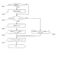
本実施形態の状態検知装置100を用いて状態検知を行う処理の流れを、図1に示すフローチャートを用いて説明する。ここでは、蓄電池10の充放電履歴を判定する方法を詳細に説明している。まず、ステップS1において、状態検知部110が入出力手段130から充放電履歴判定を要求する信号を入力すると、ステップS2で蓄電池10を負荷2から切断できるか否かを判定する。この判定では、例えば蓄電池10の切断許可が対象システム1あるいは対象システム1のユーザ等から事前に与えられているときに、切断可能と判定させるようにする。
ステップS2で蓄電池10の切断が不可と判定されると、充放電履歴判定の処理を終了する。一方、ステップS2で蓄電池10の切断が可能と判定されると、ステップS3で蓄電池10を負荷2から切断する。つぎのステップS4では、電流測定手段13から電流測定値を入力して所定の停止時電流閾値と比較し、電流測定値が停止時電流閾値以下のときに充放電停止と判定させる。充放電停止の判定では、電流測定値が0のときのみに限定する必要はなく、例えば計測器、制御器、通信機等で微小な電流(暗電流)が消費されているとき等も充放電停止と判定させるようにしてもよい。
ステップS4で電流測定値が停止時電流閾値より大きいときは、ステップS5で例えば「充放電履歴判定エラー」等を入出力手段130に出力して処理を終了する。一方、ステップS4で充放電停止と判定されると、ステップS6で蓄電池10に充放電手段11を接続し、予め設定されている所定容量の電流積算値、すなわちプローブパルスを蓄電池10に印加する。
次のステップS7では、充放電手段11を蓄電池10から切断するとともに、このときの時刻tをtbとして記憶する。時刻tbは、図6に示すtbに相当する。ステップS8では、電流測定手段13から電流測定値を入力して停止時電流閾値と比較し、電流測定値が停止時電流閾値以下のときは充放電停止中と判定してステップS9に進む。一方、電流測定値が停止時電流閾値より大きいときはステップS5に進み、入出力手段130に「充放電履歴判定エラー」等を出力して処理を終了する。
ステップS9では、時刻tが所定の時刻区間ts1~ts2(ts1<ts2)に達したか、すなわち時刻tが時刻ts1以降か否かを判定し、時刻tが時刻ts1以降であると判定したときはステップS10に進む。一方、時刻ts1に達していないと判定したときは、所定の時間間隔(状態検知周期)後に再びステップS8に戻る。ここで、時刻区間ts1~ts2は、図6に示す時刻tb~tcの期間に含まれる。ステップS10では、式(1)に基づいてOCV測定値OCV_now(t)に時間間隔を乗算したものをOCV積分値Sts1_ts2に加算する。続くステップS11では、時刻tが時刻区間ts1~ts2の最後に達したか否かを判定し、時刻tがts2に達していないときは所定の時間間隔後に再びステップS8に戻る。一方、時刻tがts2に達しているときはステップS12に進む。
ステップS12では、時刻tがtcに達するのを待ち、そのときのOCVを測定してこれをOCV_base=OCV_now(tc)として記憶させる。次のステップS13では、ステップS10で算出したSts1_ts2とステップS12で記憶させたOCV_baseとから、式(2)に基づいてOCV変化積分値DSts1_ts2を算出する。ここで、式(2)におけるΔtは、Δt=ts2-ts1で与えられる。ステップS14では、予め記憶部120に保存されている充放電履歴判定値Th1、Th2を読出し、式(3)、(4)に基づいて蓄電池10の充放電履歴を判定する。充放電履歴の判定結果は、ステップS15で入出力手段130から外部に出力される。
(第2実施形態)
本発明の第2の実施形態に係る蓄電デバイスの蓄電デバイスの状態検知方法を、図8を用いて説明する。図8は、本実施形態の蓄電デバイスの状態検知方法における処理の流れを説明するためのフローチャートである。本実施形態の蓄電デバイスの状態検知方法では、第1実施形態の蓄電デバイスの状態検知方法で判定した充放電履歴判定結果に基づいて、蓄電池10のSOCを高精度に算出できるようにしたものである。
本発明の第2の実施形態に係る蓄電デバイスの蓄電デバイスの状態検知方法を、図8を用いて説明する。図8は、本実施形態の蓄電デバイスの状態検知方法における処理の流れを説明するためのフローチャートである。本実施形態の蓄電デバイスの状態検知方法では、第1実施形態の蓄電デバイスの状態検知方法で判定した充放電履歴判定結果に基づいて、蓄電池10のSOCを高精度に算出できるようにしたものである。
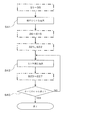
図1に示したステップS1~S14の処理の結果に基づき、ステップS21では充放電履歴が放電かあるいは充電かを判定する。その結果、放電履歴であると判定されるとステップS22に進む一方、充電履歴であると判定されるとステップS23に進む。ステップS6で蓄電池10に印加したプローブパルスが所定容量の充電であることから、ステップS21で放電履歴であると判定されたときは、放電の後にプローブパルスの印加で充電を行ったことになる。その結果、蓄電池10の内部状態が放電の影響と充電の影響を混在させた状態になっていることが判る。そこで、この場合にはステップS22で、所定容量の放電を行う(以下ではこれを状態検知前放電という)。これにより、図4(a)に示した充放電履歴と同様の放電、充電、放電を順次行ったことになり、図5の符号33で示した緩和量と同様に、中間SOCの変化に対して単調に変化する緩和量が得られるようになる。
なお、ここではステップS6で印加されるプローブパルスが所定容量の充電である場合について説明するが、プローブパルスが所定容量の放電である場合には、ステップS21で充放電履歴が充電であると判定されたときにステップS22に進み、放電であると判定されたときにはステップS23に進むようにする。また、この場合にはステップS22で所定容量の充電(状態検知前充電)を行う。
状態検知前放電(あるいは状態検知前充電)として行う放電量(あるいは充電量)は、蓄電池10の種類、型番、容量、及び複数のセルを組み合わせて構成されている場合にはその組み合わせ数等に応じて好適に決定する。一例として、18650型の燐酸鉄系Liイオン電池の場合には、状態検知前放電として新品容量換算で2%以上の放電を行うのが望ましい。
また、プローブパルスで印加する充電容量(放電容量)の絶対値は、状態検知前放電(状態検知前充電)で放電(充電)する放電容量(充電容量)の絶対値よりも小さくするのがよい。これにより、プローブパルスの印加による充電履歴(放電履歴)の影響を、その後行う状態検知前放電(状態検知前充電)により大幅に低減させることができ、放電(充電)のみを行ったときの中間SOCと緩和量との関係に近づけることが可能となる。一例として、燐酸鉄系Liイオン電池の場合には、プローブパルスの充放電を新品容量換算で0.5%の充電とするのがよい。
ステップS22で状態検知前放電が行われると、次にステップS23に進む。ステップS23では、安定時OCVに略等しいOCV_baseがOCV1以上かつOCV2以下であるかを判定する。OCV_baseがOCV1以上かつOCV2以下のときはステップS24に進む一方、OCV_baseがOCV1より小さいかあるいはOCV2より大きいときはステップS26に進む。
ステップS24では、式(1)または式(2)に基づいて緩和量を算出する。緩和量として式(1)から算出されるOCV積分値St1_t2を用いるときは、所定の緩和期間中にステップS8~S11と同様の処理を行ってOCV積分値St1_t2を算出する。また、緩和量として式(2)から算出されるOCV変化積分値DSt1_t2を用いるときは、所定の緩和期間中にステップS8~S13と同様の処理を行ってOCV変化積分値DSt1_t2を算出する。
次のステップS25では、ステップS23で算出された緩和量を用いて緩和量対SOCの関係から蓄電池10のSOCを算出する。緩和量対SOCの関係は、図5の符号33で示すような中間SOCに対する緩和量の変化の関係を事前に求め、これをもとに作成することができる。事前に作成された緩和量対SOCの関係は記憶部120に保存され、ステップS25で記憶部120から読み出してSOCの算出に用いられる。ステップS25でSOCが算出されると、次にステップS27に進む。
一方ステップS26では、OCV_baseを安定時OCVとして安定時OCV対SOCの関係からSOCを算出する。安定時OCV対SOCの関係は、図3に示したSOCに対する安定時OCV21の変化を事前に求め、これをもとに作成することができる。事前に作成された安定時OCV対SOCの関係は記憶部120に保存され、ステップS26で記憶部120から読み出してSOCの算出に用いられる。ステップS26でSOCが算出されると、次のステップS27に進む。
ステップS27では、ステップS26またはS27で算出されたSOCを入出力手段130から外部に出力される。なお、OCV_baseを取得する基準時間は、状態検知前充放電制御の終了から30分以上経過した時間とするのが好ましく、例えば燐酸鉄系Liイオン電池では1時間程度とするのがよい。基準時間は、電池の大きさや種類等によって異なる。
(第3実施形態)
本発明の第3の実施形態に係る蓄電デバイスの状態検知方法を、図9を用いて説明する。図9は、本実施形態の蓄電デバイスの状態検知方法による処理の流れを説明するためのフローチャートである。
本発明の第3の実施形態に係る蓄電デバイスの状態検知方法を、図9を用いて説明する。図9は、本実施形態の蓄電デバイスの状態検知方法による処理の流れを説明するためのフローチャートである。
第2実施形態の状態検知方法では、ステップS21で放電履歴と判定されたときのみステップS22で状態検知前放電を行うようにしていた。これに対し、本実施形態の蓄電デバイスの状態検知方法では、ステップS21で放電履歴でない、すなわち充電履歴と判定されたときには、ステップS31で状態検知前充電を行うようにしている。これにより、充電停止後の蓄電池の内部状態に対応した緩和量対SOCの関係を用いて、さらに高精度にSOCを算出することが可能となる。
(第4実施形態)
本発明の第4の実施形態に係る蓄電デバイスの状態検知方法を、図10、11を用いて説明する。図10は、複数のセルを組み合わせて構成された蓄電デバイス10'を示すブロック図である。蓄電デバイス10'は、それぞれ6個のセル10a~10f及び10g~10lを直列に接続したものを並列に接続して構成されている。このように複数のセルから構成されている蓄電デバイス10'では、充放電履歴を判定するのにすべてのセルにプローブパルスを印加する必要はなく、一部のセルにプローブパルスを印加するだけで判定することができる。
本発明の第4の実施形態に係る蓄電デバイスの状態検知方法を、図10、11を用いて説明する。図10は、複数のセルを組み合わせて構成された蓄電デバイス10'を示すブロック図である。蓄電デバイス10'は、それぞれ6個のセル10a~10f及び10g~10lを直列に接続したものを並列に接続して構成されている。このように複数のセルから構成されている蓄電デバイス10'では、充放電履歴を判定するのにすべてのセルにプローブパルスを印加する必要はなく、一部のセルにプローブパルスを印加するだけで判定することができる。
図11に、本実施形態の蓄電デバイスの状態検知方法による処理の流れを説明するためのフローチャートを示す。本実施形態の蓄電デバイスの状態検知方法では、ステップS1~S5の処理の後、ステップS41でプローブパルスを印加するセルを選択する。そして、選択されたセルに対し、ステップS6~S15の処理を行って充放電履歴を判定する。その後、SOCを算出するためにまず、ステップS21、S22で必要に応じて状態検知前放電を行う。さらに、ステップS42、S43の処理によりすべてのセルに対してステップS23~S27の処理を行う。これにより、すべてのセルのSOCを算出することができる。
上記説明のように、本発明の蓄電デバイスの状態検知方法及び状態検知装置によれば、蓄電デバイスの充放電履歴を高精度に判定することができる。また、充放電履歴を判定することで、必要に応じて蓄電デバイスに状態検知前充電または状態検知前放電を印加することができ、これによりSOCを高精度に求めることが可能となる。その結果、蓄電デバイスを搭載したシステムの運用を容易とし、システムの稼動率や安全性の向上、さらに管理コストの低減を図ることが可能となる。
なお、本実施の形態における記述は、本発明に係る蓄電デバイスの状態検知方法及び状態検知装置の一例を示すものであり、これに限定されるものではない。本実施の形態における蓄電デバイスの状態検知方法及び状態検知装置の細部構成及び詳細な動作等に関しては、本発明の趣旨を逸脱しない範囲で適宜変更可能である。
1:対象システム
2:負荷
10:蓄電デバイス
11:充放電手段
12:電圧測定手段
13:電流測定手段
14:温度測定手段
100:状態検知装置
110:状態検知部
120:記憶部
130:入出力手段
2:負荷
10:蓄電デバイス
11:充放電手段
12:電圧測定手段
13:電流測定手段
14:温度測定手段
100:状態検知装置
110:状態検知部
120:記憶部
130:入出力手段
Claims (15)
- 充放電停止後に停止前の充放電履歴を判定する蓄電デバイスの状態検知方法であって、
第1容量の充電または放電をプローブパルスとして前記蓄電デバイスに印加し、
前記プローブパルス印加後の第1の期間に前記蓄電デバイスの開回路電圧(OCV)の測定値を取得し、
前記OCV測定値から所定の履歴判定用状態量を算出し、
前記履歴判定用状態量と事前に作成された参照データとから前記充放電履歴が充電履歴あるいは放電履歴であると判定する
ことを特徴とする蓄電デバイスの状態検知方法。 - 前記履歴判定用状態量は、前記プローブパルス印加後の第1の期間にわたって前記OCV測定値を時間積分して算出したOCV積分値であり、
前記参照データは、前記OCV積分値に対する閾値であり、前記OCV積分値を前記参照データと比較することで前記充放電履歴が充電履歴あるいは放電履歴であると判定する
ことを特徴とする請求項1に記載の蓄電デバイスの状態検知方法。 - 前記履歴判定用状態量は、前記OCV測定値の所定の基準OCVからの変化量を時間積分したOCV変化積分値であり、
前記参照データは、前記OCV変化積分値に対する閾値であり、
前記プローブパルス印加後の前記第1の期間が経過したときの前記OCV測定値を取得して前記基準OCVとし、
前記OCV測定値を時間積分したOCV積分値から前記基準OCVに前記第1の期間の時間長を乗じた値を減算して前記OCV変化積分値を算出し、
前記OCV変化積分値を前記参照データと比較することで前記充放電履歴が充電履歴あるいは放電履歴であると判定する
ことを特徴とする請求項1に記載の蓄電デバイスの状態検知方法。 - 前記参照データとして所定の第1閾値及び該第1閾値より大きい第2の閾値を予め設定しておき、前記OCV積分値または前記OCV変化積分値が前記第1閾値より小さいときに前記充放電履歴を放電履歴と判定する一方、前記OCV積分値または前記OCV変化積分値が前記第2の閾値より大きいときに前記充放電履歴を充電履歴と判定する
ことを特徴とする請求項2または3に記載の蓄電デバイスの状態検知方法。 - 前記履歴判定用状態量は、前記OCV測定値と所定の基準OCVとの差である電圧降下量であり、
前記参照データは、電圧降下量の時間変化を表す関数または表であり、
前記電圧降下量を前記充放電停止からの経過時間に対応する前記参照データと比較し、
前記電圧降下量が前記参照データより小さいときに前記充放電履歴を放電履歴と判定する一方、前記電圧降下量が前記参照データより大きいときに前記充放電履歴を充電履歴と判定する
ことを特徴とする請求項1に記載の蓄電デバイスの状態検知方法。 - 前記第1容量の充電または放電は、前記蓄電デバイスの新品換算容量の5%以下である
ことを特徴とする請求項1乃至5のいずれか1項に記載の蓄電デバイスの状態検知方法。 - 前記蓄電デバイスの電流測定値が所定の停止時電流閾値以下のときを前記充放電停止と判定する
ことを特徴とする請求項1乃至6のいずれか1項に記載の蓄電デバイスの状態検知方法。 - 前記プローブパルスが前記第1容量の充電でかつ前記充放電履歴が充電履歴のとき、あるいは前記プローブパルスが前記第1容量の放電でかつ前記充放電履歴が放電履歴のときには、予め設定された残容量(SOC)算出式を用いて前記OCV積分値または前記OCV変化積分値あるいは前記基準OCVから前記蓄電デバイスのSOCを算出する
ことを特徴とする請求項1乃至7のいずれか1項に記載の蓄電デバイスの状態検知方法。 - 前記充放電履歴が充電履歴かあるいは放電履歴かによってそれぞれ第2容量の充電あるいは放電を前記蓄電デバイスに印加し、
前記第2容量の充電あるいは放電を印加後に前記OCV積分値または前記OCV変化積分値と前記基準OCVとを求め、
予め設定されたSOC算出式を用いて前記OCV積分値または前記OCV変化積分値あるいは前記基準OCVから前記蓄電デバイスのSOCを算出する
ことを特徴とする請求項1乃至7のいずれか1項に記載の蓄電デバイスの状態検知方法。 - 前記充放電履歴が充電履歴で前記プローブパルスが前記第1容量の放電のときには第2容量の充電を前記蓄電デバイスに印加し、あるいは前記充放電履歴が放電履歴で前記プローブパルスが前記第1容量の充電のときには前記第2容量の放電を前記蓄電デバイスに印加し、
前記第2容量の充電あるいは放電を印加後に前記OCV積分値または前記OCV変化積分値と前記基準OCVとを求め、
予め設定されたSOC算出式を用いて前記OCV積分値または前記OCV変化積分値あるいは前記基準OCVから前記蓄電デバイスのSOCを算出する
ことを特徴とする請求項1乃至7のいずれか1項に記載の蓄電デバイスの状態検知方法。 - 前記充放電履歴が充電履歴で前記プローブパルスが前記第1容量の充電のときには第2容量の充電を前記蓄電デバイスに印加し、
前記第2容量の充電を印加後に前記OCV積分値または前記OCV変化積分値と前記基準OCVとを求め、
予め設定されたSOC算出式を用いて前記OCV積分値または前記OCV変化積分値あるいは前記基準OCVから前記蓄電デバイスのSOCを算出する
ことを特徴とする請求項1乃至7のいずれか1項に記載の蓄電デバイスの状態検知方法。 - 前記第2容量は、前記第1容量より大きい
ことを特徴とする請求項9乃至11のいずれか1項に記載の蓄電デバイスの状態検知方法。 - 前記蓄電デバイスは、複数のセルを直列または並列に接続して構成されており、
前記プローブパルスを前記複数のセルの少なくとも1つに印加して前記充放電履歴を判定し、
前記第2容量の充電あるいは放電を前記複数のセルすべてに印加してそれぞれのSOCを算出する
ことを特徴とする請求項9乃至12のいずれか1項に記載の蓄電デバイスの状態検知方法。 - 前記SOC算出式は、OCV積分値またはOCV変化積分値対SOCの関係式、あるいは基準OCV対SOCの関係式であり、
前記基準OCVが所定の範囲にあるときは、前記OCV積分値またはOCV変化積分値対SOCの関係式を用いて前記OCV積分値または前記OCV変化積分値から前記SOCを算出し、
前記基準OCVが前記所定の範囲外にあるときは、前記基準OCV対SOCの関係式を用いて前記基準OCVから前記SOCを算出する
ことを特徴とする請求項8乃至11のいずれか1項に記載の蓄電デバイスの状態検知方法。 - 充放電手段を用いて充放電可能な蓄電デバイスの充放電停止後に停止前の充放電履歴を判定する蓄電デバイスの状態検知装置であって、
記憶部と、
プローブパルスとして第1容量の充電または放電を前記蓄電デバイスに印加するように前記充放電手段を制御し、前記プローブパルス印加後の第1の期間に前記蓄電デバイスの開回路電圧(OCV)の測定値を取得し、前記プローブパルス印加後の第1の時間が経過したときの前記OCV測定値を取得して基準OCVとし、前記第1の期間にわたって前記OCV測定値を時間積分したOCV積分値から前記基準OCVに前記第1の期間の時間長を乗じた値を減算してOCV変化積分値を算出し、前記OCV変化積分値を所定の閾値と比較することで前記充放電履歴が充電履歴あるいは放電履歴であると判定する状態検知部と、
前記状態検知部から前記充放電履歴の判定結果を入力して外部に出力する入出力手段と、を備える
ことを特徴とする蓄電デバイスの状態検知装置。
Applications Claiming Priority (2)
| Application Number | Priority Date | Filing Date | Title |
|---|---|---|---|
| JP2011-092946 | 2011-04-19 | ||
| JP2011092946A JP5804759B2 (ja) | 2011-04-19 | 2011-04-19 | 蓄電デバイスの状態検知方法及び状態検知装置 |
Publications (1)
| Publication Number | Publication Date |
|---|---|
| WO2012144516A1 true WO2012144516A1 (ja) | 2012-10-26 |
Family
ID=47041622
Family Applications (1)
| Application Number | Title | Priority Date | Filing Date |
|---|---|---|---|
| PCT/JP2012/060446 Ceased WO2012144516A1 (ja) | 2011-04-19 | 2012-04-18 | 蓄電デバイスの状態検知方法及び状態検知装置 |
Country Status (2)
| Country | Link |
|---|---|
| JP (1) | JP5804759B2 (ja) |
| WO (1) | WO2012144516A1 (ja) |
Families Citing this family (3)
| Publication number | Priority date | Publication date | Assignee | Title |
|---|---|---|---|---|
| CN103645441B (zh) * | 2013-11-29 | 2016-06-01 | 中国科学院金属研究所 | 一种钒电池运行过程中充/放电状态的判断方法 |
| KR102980820B1 (ko) * | 2023-09-08 | 2026-06-23 | 주식회사 엘지에너지솔루션 | 배터리 관리 장치 및 그것의 동작 방법 |
| WO2025197446A1 (ja) * | 2024-03-22 | 2025-09-25 | パナソニックIpマネジメント株式会社 | 電池状態推定システム、電池状態推定方法、及び電池状態推定プログラム |
Citations (3)
| Publication number | Priority date | Publication date | Assignee | Title |
|---|---|---|---|---|
| JPH11289685A (ja) * | 1998-04-01 | 1999-10-19 | Toshiba Battery Co Ltd | 二次電池の充電状態検出装置 |
| JP2002181907A (ja) * | 2000-12-13 | 2002-06-26 | Nissan Motor Co Ltd | 自動車用バッテリの充電状態検出装置 |
| JP2008292380A (ja) * | 2007-05-26 | 2008-12-04 | Sanyo Electric Co Ltd | 電池の残容量の検出方法 |
-
2011
- 2011-04-19 JP JP2011092946A patent/JP5804759B2/ja active Active
-
2012
- 2012-04-18 WO PCT/JP2012/060446 patent/WO2012144516A1/ja not_active Ceased
Patent Citations (3)
| Publication number | Priority date | Publication date | Assignee | Title |
|---|---|---|---|---|
| JPH11289685A (ja) * | 1998-04-01 | 1999-10-19 | Toshiba Battery Co Ltd | 二次電池の充電状態検出装置 |
| JP2002181907A (ja) * | 2000-12-13 | 2002-06-26 | Nissan Motor Co Ltd | 自動車用バッテリの充電状態検出装置 |
| JP2008292380A (ja) * | 2007-05-26 | 2008-12-04 | Sanyo Electric Co Ltd | 電池の残容量の検出方法 |
Also Published As
| Publication number | Publication date |
|---|---|
| JP5804759B2 (ja) | 2015-11-04 |
| JP2012225740A (ja) | 2012-11-15 |
Similar Documents
| Publication | Publication Date | Title |
|---|---|---|
| Zheng et al. | A novel capacity estimation method for lithium-ion batteries using fusion estimation of charging curve sections and discrete Arrhenius aging model | |
| CN110914696B (zh) | 用于在电池的操作期间估计电池开路池格电压、充电状态以及健康状态的方法和系统 | |
| JP6033155B2 (ja) | 電池制御装置 | |
| US9841465B2 (en) | Battery DC impedance measurement | |
| JP6324248B2 (ja) | 電池状態検知装置、二次電池システム、電池状態検知プログラム、電池状態検知方法 | |
| EP3002597B1 (en) | Battery control device | |
| KR101956088B1 (ko) | 상태 관리 장치, 축전 소자의 균등화 방법 | |
| Eichi et al. | Modeling and analysis of battery hysteresis effects | |
| US8823326B2 (en) | Method for determining the state of charge of a battery in charging or discharging phase | |
| KR20150024561A (ko) | 배터리 관리 시스템 및 그 구동방법 | |
| CN105467325A (zh) | 电池容量退化解决的方法和系统 | |
| JP5619744B2 (ja) | 蓄電デバイスの状態検知方法及びその装置 | |
| JP5409840B2 (ja) | 組電池のセルの状態推定装置 | |
| JP2016023967A (ja) | 電池状態検知装置、二次電池システム、電池状態検知プログラム、電池状態検知方法 | |
| CN106997026B (zh) | 用于确定铅酸蓄电池的剩余电容量的方法和装置 | |
| JPWO2017169088A1 (ja) | リチウムイオン二次電池の寿命推定装置 | |
| CN103872727B (zh) | 一种锂离子动力电池最大使用电流的确定方法 | |
| CN102893169A (zh) | 蓄电设备的状态检测方法及其装置 | |
| Yang et al. | Lithium-ion battery SOH estimation and fault diagnosis with missing data | |
| Yang et al. | A lithium-ion battery RUL prognosis method using temperature changing rate | |
| CN104833917A (zh) | 用于锂蓄电池中荷电状态实时估算的标称电池电阻的确定 | |
| JP5804759B2 (ja) | 蓄電デバイスの状態検知方法及び状態検知装置 | |
| CN105974328A (zh) | 二次电池的实际容量的测量方法和装置、无人机 | |
| Si et al. | Research on estimation of battery state of electric vehicle battery management system | |
| CN110873842A (zh) | 电源系统 |
Legal Events
| Date | Code | Title | Description |
|---|---|---|---|
| 121 | Ep: the epo has been informed by wipo that ep was designated in this application |
Ref document number: 12774634 Country of ref document: EP Kind code of ref document: A1 |
|
| NENP | Non-entry into the national phase |
Ref country code: DE |
|
| 122 | Ep: pct application non-entry in european phase |
Ref document number: 12774634 Country of ref document: EP Kind code of ref document: A1 |