WO2012144470A1 - 表示装置、および制御方法 - Google Patents
表示装置、および制御方法 Download PDFInfo
- Publication number
- WO2012144470A1 WO2012144470A1 PCT/JP2012/060290 JP2012060290W WO2012144470A1 WO 2012144470 A1 WO2012144470 A1 WO 2012144470A1 JP 2012060290 W JP2012060290 W JP 2012060290W WO 2012144470 A1 WO2012144470 A1 WO 2012144470A1
- Authority
- WO
- WIPO (PCT)
- Prior art keywords
- image
- display
- display mode
- gamma correction
- display device
- Prior art date
- Legal status (The legal status is an assumption and is not a legal conclusion. Google has not performed a legal analysis and makes no representation as to the accuracy of the status listed.)
- Ceased
Links
Images





Classifications
-
- G—PHYSICS
- G09—EDUCATION; CRYPTOGRAPHY; DISPLAY; ADVERTISING; SEALS
- G09G—ARRANGEMENTS OR CIRCUITS FOR CONTROL OF INDICATING DEVICES USING STATIC MEANS TO PRESENT VARIABLE INFORMATION
- G09G3/00—Control arrangements or circuits, of interest only in connection with visual indicators other than cathode-ray tubes
- G09G3/20—Control arrangements or circuits, of interest only in connection with visual indicators other than cathode-ray tubes for presentation of an assembly of a number of characters, e.g. a page, by composing the assembly by combination of individual elements arranged in a matrix no fixed position being assigned to or needed to be assigned to the individual characters or partial characters
- G09G3/34—Control arrangements or circuits, of interest only in connection with visual indicators other than cathode-ray tubes for presentation of an assembly of a number of characters, e.g. a page, by composing the assembly by combination of individual elements arranged in a matrix no fixed position being assigned to or needed to be assigned to the individual characters or partial characters by control of light from an independent source
- G09G3/36—Control arrangements or circuits, of interest only in connection with visual indicators other than cathode-ray tubes for presentation of an assembly of a number of characters, e.g. a page, by composing the assembly by combination of individual elements arranged in a matrix no fixed position being assigned to or needed to be assigned to the individual characters or partial characters by control of light from an independent source using liquid crystals
- G09G3/3611—Control of matrices with row and column drivers
- G09G3/3648—Control of matrices with row and column drivers using an active matrix
-
- G—PHYSICS
- G02—OPTICS
- G02F—OPTICAL DEVICES OR ARRANGEMENTS FOR THE CONTROL OF LIGHT BY MODIFICATION OF THE OPTICAL PROPERTIES OF THE MEDIA OF THE ELEMENTS INVOLVED THEREIN; NON-LINEAR OPTICS; FREQUENCY-CHANGING OF LIGHT; OPTICAL LOGIC ELEMENTS; OPTICAL ANALOGUE/DIGITAL CONVERTERS
- G02F1/00—Devices or arrangements for the control of the intensity, colour, phase, polarisation or direction of light arriving from an independent light source, e.g. switching, gating or modulating; Non-linear optics
- G02F1/01—Devices or arrangements for the control of the intensity, colour, phase, polarisation or direction of light arriving from an independent light source, e.g. switching, gating or modulating; Non-linear optics for the control of the intensity, phase, polarisation or colour
- G02F1/13—Devices or arrangements for the control of the intensity, colour, phase, polarisation or direction of light arriving from an independent light source, e.g. switching, gating or modulating; Non-linear optics for the control of the intensity, phase, polarisation or colour based on liquid crystals, e.g. single liquid crystal display cells
- G02F1/1323—Arrangements for providing a switchable viewing angle
-
- G—PHYSICS
- G09—EDUCATION; CRYPTOGRAPHY; DISPLAY; ADVERTISING; SEALS
- G09G—ARRANGEMENTS OR CIRCUITS FOR CONTROL OF INDICATING DEVICES USING STATIC MEANS TO PRESENT VARIABLE INFORMATION
- G09G2320/00—Control of display operating conditions
- G09G2320/02—Improving the quality of display appearance
- G09G2320/028—Improving the quality of display appearance by changing the viewing angle properties, e.g. widening the viewing angle, adapting the viewing angle to the view direction
-
- G—PHYSICS
- G09—EDUCATION; CRYPTOGRAPHY; DISPLAY; ADVERTISING; SEALS
- G09G—ARRANGEMENTS OR CIRCUITS FOR CONTROL OF INDICATING DEVICES USING STATIC MEANS TO PRESENT VARIABLE INFORMATION
- G09G2320/00—Control of display operating conditions
- G09G2320/06—Adjustment of display parameters
- G09G2320/0673—Adjustment of display parameters for control of gamma adjustment, e.g. selecting another gamma curve
-
- G—PHYSICS
- G09—EDUCATION; CRYPTOGRAPHY; DISPLAY; ADVERTISING; SEALS
- G09G—ARRANGEMENTS OR CIRCUITS FOR CONTROL OF INDICATING DEVICES USING STATIC MEANS TO PRESENT VARIABLE INFORMATION
- G09G2320/00—Control of display operating conditions
- G09G2320/06—Adjustment of display parameters
- G09G2320/068—Adjustment of display parameters for control of viewing angle adjustment
Definitions
- the present invention relates to a display device capable of switching between a multi-view display mode or a 3D display mode and a normal display mode.
- a parallax barrier is provided on the front surface (user side) of the display screen, the viewing direction in which an image is displayed is limited by the parallax barrier, and a plurality of different viewing directions
- a display device that performs multi-view display that displays the image so as to be visible.
- a case where different images are displayed in two directions is referred to as dual view (two visual field directions) display.
- dual view two visual field directions
- a case where a common image is displayed in any viewing direction without using a parallax barrier is referred to as normal display.
- Such a display device it is possible to switch between the multi-view display mode and the normal display mode by switching the validity / invalidity of the parallax barrier made of liquid crystal or the like. For example, when two people want to view different images, view each image from the left and right viewing directions in multi-view display mode, and when one person wants to view images, view the image from the front in normal display mode You can use it.
- Patent Documents 1 and 2 Examples of display devices that can switch between the multi-view display mode and the normal display mode are disclosed in Patent Documents 1 and 2.
- Japanese Patent Publication Japanese Unexamined Patent Publication No. 2007-212888 (published on August 23, 2007)” Japanese Patent Publication “Japanese Patent Laid-Open No. 2008-236283 (published on October 2, 2008)”
- the conventional configuration does not take into account that the gamma characteristic of the liquid crystal display panel itself varies depending on the angle of the viewing direction (viewpoint position) with respect to the display screen. For this reason, the user has not been able to view an image under optimum conditions in either the multi-view display mode or the normal display mode.
- the brightness when a pixel of a certain gradation is viewed from the front direction with respect to the display screen is different from the brightness when the display screen is viewed from an oblique direction.
- the luminance when a pixel of a certain gradation T1 is viewed from the front direction is L1
- the luminance when the pixel is viewed from a predetermined oblique direction is L1 '
- the luminance of the pixel of another gradation T2 viewed from the front direction is L2
- the luminance of the pixel viewed from the predetermined oblique direction is L2 '.
- the ratio of L1 and L2 and the ratio of L2 and L2 ' are not the same. That is, the brightness ratio between the bright gradation pixels and the dark gradation pixels appears different in the front direction and the oblique direction. This phenomenon is remarkable in the intermediate gradation.
- This problem is caused by the difference in the gamma characteristic of the liquid crystal display panel between the front direction and the diagonal direction.
- the liquid crystal molecules of each pixel in the liquid crystal display panel are oriented at an angle (obliquely) with respect to the display screen in the intermediate gray scale display state.
- a part of the light of the backlight is transmitted to express intermediate gradation.
- the ratio between the amount of light emitted from the pixel in the front direction and the amount of light emitted in the oblique direction is different, so the gamma characteristic is different between the front direction and the oblique direction. It will be different.
- the gamma characteristic in the normal display mode becomes inappropriate.
- the present invention has been made in view of the above-described problems, and an object thereof is to realize a display device that performs display suitable for a display mode for each display mode in which viewing directions for displaying images are different from each other. It is in.
- the display device is a display device capable of displaying an image with different viewing angle regions, and in order to solve the above-mentioned problem, the viewing angle region displaying the image And a gamma correction unit that performs different gamma correction on the image.
- a display device control method is a display device control method capable of displaying an image with different viewing angle regions, and in order to solve the above-described problem, Different gamma correction is performed on the image in accordance with the viewing angle region to be displayed.
- an image can be displayed with an appropriate gamma characteristic with respect to the viewing direction in which each image is displayed according to the viewing angle region in which the image is displayed. Therefore, the display device can display an image with an appropriate gamma characteristic with respect to an assumed user direction according to each image.
- the display device and the control method for the display device according to the present invention display images with appropriate gamma characteristics with respect to the viewing direction for displaying each image according to the viewing angle region for displaying the image. be able to.
- the display device can display an image with an appropriate gamma characteristic with respect to an assumed user direction according to each image.
- FIG. 1 is a block diagram showing a schematic configuration of the display device 1 of the present embodiment.
- the display device 1 includes a liquid crystal display panel (liquid crystal display unit) 2, a first gate driver 3, a first source driver 4, a first timing signal generation unit 5, a parallax barrier 7, a second gate driver 8, and a second source driver 9.
- a second timing signal generation unit 10 a display mode switching unit (display switching unit) 11, a parallax barrier control unit (viewing angle control unit) 12, a display control unit 13, a gamma data storage unit 14, and a gamma correction unit 15. .
- the liquid crystal display panel 2 displays an image based on a video signal input to the display device 1.
- the liquid crystal display panel 2 includes m scanning signal lines extending in parallel with each other, n data signal lines extending in parallel with each other, and pixels arranged in a matrix.
- the pixel is formed in a region surrounded by two adjacent scanning signal lines and two adjacent data signal lines, and includes a switching element and a liquid crystal capacitor.
- the first gate driver 3 sequentially generates scanning signals to be applied to the scanning signal lines based on various timing signals such as a gate clock signal (GCK) and a gate start pulse (GSP) output from the first timing signal generator 5. To do.
- the scanning signal lines are connected to the pixels in each row of the liquid crystal display panel 2.
- the first source driver 4 generates an analog gradation data signal to be output to each pixel from the video data output from the gamma correction unit 15.
- the first source driver 4 converts the digital video data received from the gamma correction unit 15 into a data signal indicating an analog gradation voltage according to the gradation of the digital video data.
- the gradation of each pixel is represented by a digital signal.
- the data signal the gradation of each pixel is represented by a voltage level corresponding to the gradation.
- the first source driver 4 converts the voltage into a voltage corresponding to each gradation in consideration of the non-linear characteristic of the applied voltage-transmittance of the liquid crystal display panel 2.
- the first source driver 4 outputs a data signal to the data signal line based on the source clock signal (SCK) and the source start pulse (SSP) output from the first timing signal generator 5.
- the data signal lines are connected to the pixels in each column of the liquid crystal display panel 2.
- the first timing signal generator 5 outputs timing signals such as a source clock signal (SCK) and a source start pulse (SSP) to the first source driver 4.
- the first timing signal generator 5 outputs timing signals such as a gate clock signal (GCK) and a gate start pulse (GSP) to the first gate driver 3.
- SCK source clock signal
- SSP source start pulse
- GSP gate start pulse
- the parallax barrier 7 is provided on the front surface (user side) of the liquid crystal display panel 2.
- the parallax barrier 7 includes m ′ scanning signal lines extending in parallel with each other, n ′ data signal lines extending in parallel with each other, and cells arranged in a matrix. This cell is formed in a region surrounded by two adjacent scanning signal lines and two adjacent data signal lines, and includes a switching element and a liquid crystal capacitor. Each cell of the parallax barrier 7 can switch whether to transmit the light emitted from the pixels of the liquid crystal display panel 2 on the back according to the applied voltage.
- the cell rows of the parallax barrier 7 are arranged so as to be positioned between the pixel rows of the liquid crystal display panel 2.
- the cells of the parallax barrier 7 transmit light from the back. Therefore, in the normal display mode, the image displayed on the liquid crystal display panel 2 can be viewed from an arbitrary direction.
- the cells of the parallax barrier 7 are made transparent / non-transparent every other row in a stripe shape. Therefore, the viewing direction in which the image on the liquid crystal display panel 2 can be viewed is limited for each pixel column, and separate images are displayed in two oblique viewing directions on the left and right.
- the second gate driver 8 sequentially generates scanning signals to be applied to the scanning signal lines based on various timing signals such as a gate clock signal (GCK) and a gate start pulse (GSP) output from the second timing signal generator 10. To do.
- the scanning signal lines are connected to the cells in each row of the parallax barrier 7.
- the second source driver 9 generates a parallax barrier signal to be output to each cell based on the parallax barrier data output from the parallax barrier control unit 12.
- the second source driver 9 outputs a parallax barrier signal to the data signal line based on the source clock signal (SCK) and the source start pulse (SSP) output from the second timing signal generation unit 10. This data signal line is connected to a cell in each column of the parallax barrier 7.
- the second timing signal generator 10 outputs timing signals such as a source clock signal (SCK) and a source start pulse (SSP) to the second source driver 9.
- the second timing signal generator 10 outputs timing signals such as a gate clock signal (GCK) and a gate start pulse (GSP) to the second gate driver 8.
- the display mode switching unit 11 switches between the normal display mode and the dual view display mode according to the display mode setting by the user.
- the display mode switching unit 11 outputs a display mode signal indicating the set mode to the display control unit 13, the gamma correction unit 15, and the parallax barrier control unit 12.
- the user can designate a display mode for the display device 1 using an input device such as a remote controller. Instead of being set by the user, the display mode switching unit 11 may set the display mode based on a video signal or the like input to the display device 1.
- the parallax barrier control unit 12 determines whether the display mode signal is the normal display mode or the dual view display mode based on the display mode signal received from the display mode switching unit 11. In the dual view display mode, the parallax barrier control unit 12 outputs to the second source driver 9 parallax barrier data for setting the cells of the parallax barrier 7 in a transmission / non-transmission state in a stripe shape. In the normal display mode, the parallax barrier control unit 12 outputs parallax barrier data for setting all the cells of the parallax barrier 7 to the transmissive state to the second source driver 9. In the normal display mode, the parallax barrier control unit 12 may not output the parallax barrier data to the second source driver 9. When the parallax barrier data is not input to the second source driver 9, the second source driver 9 may make all the cells of the parallax barrier 7 transparent.
- the display control unit 13 receives an input video signal from the outside of the display device 1, generates video data subjected to processing according to the display mode, and outputs the video data to the gamma correction unit 15.
- the normal display mode one image (video) is displayed using all pixels.
- the dual view display mode in order to display two images for left and right at the same time, each image is displayed using every other column of pixels. The number of pixels used to display one image is half of the total pixels. For this reason, in the dual view display mode, the display control unit 13 receives an input video signal of two videos from the outside, and a video showing an image obtained by synthesizing the two videos so as to be alternately arranged in a stripe pattern for each frame. Generate data.
- the display control unit 13 determines whether the display mode signal is the normal display mode or the dual view display mode based on the display mode signal received from the display mode switching unit 11.
- the gamma data storage unit 14 stores table data (LUT) corresponding to each of the normal display mode and the dual view display mode for performing gamma correction.
- the gamma data storage unit 14 outputs gamma table data for the normal display mode or the dual view display mode to the gamma correction unit 15 in response to a request from the gamma correction unit 15.
- the gamma correction unit 15 receives a display mode signal from the display mode switching unit 11 and acquires gamma table data for the display mode from the gamma data storage unit 14 according to the display mode.
- the gamma correction unit 15 converts the tone value of the input video data according to the acquired gamma table data (gamma correction), and applies the gamma corrected video data according to the display mode to the first source driver 4. Output.
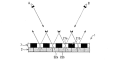
- FIG. 2 is a cross-sectional view showing a state of the liquid crystal display panel 2 and the parallax barrier 7 in the dual view display mode.
- a parallax barrier 7 is provided on the front surface (user side) of the liquid crystal display panel 2.
- the cell rows 21 a in the transmissive state and the cell rows 21 b in the non-transmissive state are alternately arranged.
- pixel rows 22a indicating the first image and pixel rows 22b indicating the second image are alternately arranged. Since the disposition of the cell row 21a in the transmissive state and the pixel rows 22a and 22b is shifted, the viewing direction (viewing angle region) in which the pixel row 22a indicating the first image can be viewed is limited, and the first image is diagonally left It is displayed with respect to the direction A, and is not displayed with respect to the direction B in the diagonally right direction.
- the viewing direction in which the pixel row 22b indicating the second image can be visually recognized is limited, and the second image is displayed in the right diagonal direction B and is not displayed in the left diagonal direction A. .
- the absolute value of the angle which each direction makes with respect to the display screen is the same for direction A and direction B.
- FIG. 3 is a sectional view showing the state of the liquid crystal display panel 2 and the parallax barrier 7 in the normal display mode.
- the parallax barrier 7 In the normal display mode, the parallax barrier 7 is set to be invalid, and each cell 21 of the parallax barrier transmits light of all the pixels 22 of the liquid crystal display panel 2 in an arbitrary direction. Therefore, the display device 1 displays one (common) image with respect to an arbitrary viewpoint direction.
- the display mode When the user has set the display mode to the normal display mode, it is assumed that the user views from the direction C in the front direction of the display screen.
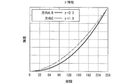
- FIG. 4 is a graph showing gamma characteristics in two viewing directions (front direction and diagonal direction) in the conventional configuration.
- the horizontal axis indicates the gradation of the pixel.
- the gradation of one color pixel of RGB is 256 gradations.
- the vertical axis indicates the luminance of the pixel observed in two viewing directions (front direction and diagonal direction).
- the luminance value is normalized according to the maximum luminance.
- the display device 1 can display an image with a gamma characteristic suitable for each display mode by switching the gamma correction in accordance with the display mode. That is, the display device 1 can display an image with a gamma characteristic suitable for viewing in the viewing direction assumed in each display mode.
- the dual view display mode In the dual view display mode, one image is represented by half of the entire pixel. Therefore, in general, in the dual view display mode, the brightness of the entire image is lower than that in the normal display mode.
- the display device 1 makes the output luminance of a backlight (not shown) larger than the output luminance in the normal display mode. Thereby, the difference in apparent brightness when the display mode is switched can be reduced. Note that even if the output luminance of the backlight is increased, the luminance of each pixel only increases uniformly, so that the gamma characteristic is not affected.
- gamma characteristic of the liquid crystal display panel 2 itself can be strictly different for each RGB color. Therefore, gamma table data for each color may be prepared in advance for each display mode, and different gamma correction may be performed for each RGB.
- the user may be able to set the gamma characteristics in each display mode.
- the gamma data storage unit 14 generates and stores gamma table data that matches the gamma characteristics set for each display mode.
- Gamma correction may be performed on the second image using gamma table data for direction B.
- the dual view display mode it is possible to perform gamma correction so that the gamma characteristics in each visual field direction are optimized for two images displayed in different visual field directions A and B.
- a 3D image may be displayed in each visual field direction in the dual view display mode (dual view 3D display mode).
- further gamma correction may be performed by switching between the dual view 2D display mode and the dual view 3D display mode, depending on whether the display is the dual view 2D display mode or the dual view 3D display mode. .
- the gamma characteristic in the direction A of the first image and the gamma characteristic in the direction B of the second image are different.
- different gamma corrections may be performed on the first image and the second image.
- the present invention is not limited to this.
- the image is entirely darker in the dual view display mode than in the normal display mode.
- gamma correction in one display mode may be included in the digital (gradation) -analog (voltage) conversion performed by the first source driver 4.
- the gamma correction unit 15 outputs the video data input from the display control unit 13 to the first source driver 4 without performing gamma correction of the video data.
- the gamma correction unit 15 performs gamma correction of the video data
- the present invention is not limited to a liquid crystal display panel, and includes a display panel whose gamma characteristics change according to the viewing direction, and a display capable of switching the viewing direction for displaying an image between the first display state and the second display state.
- Applicable to the device can be applied to a display device that realizes dual view display by controlling the directivity of a backlight without using a parallax barrier.
- the present invention can be applied to a MEMS (Micro Electro Mechanical Systems) display.
- the display mode switching unit 11 switches between the 2D display mode and the 3D display mode according to a user instruction or based on a video signal or the like input to the display device.
- the liquid crystal display panel 2 displays one image with all pixels.
- the liquid crystal display panel 2 displays left and right images alternately every other column of pixels.
- FIG. 5 is a cross-sectional view showing a state of the liquid crystal display panel 2 and the parallax barrier 7 in the 3D display mode.
- the parallax barrier 7 is provided on the front surface (user side) of the liquid crystal display panel 2 with a slight distance.
- the cell rows 21a in the transmissive state and the cell rows 21b in the non-transmissive state are alternately arranged.
- the direction of light emitted from each pixel column is limited, and the viewing direction (viewing angle) in which each pixel column can be viewed is limited.
- light that has passed through the parallax barrier 7 from each pixel row 22a that displays the first image for the right eye travels toward a predetermined viewpoint D.
- the light that has passed through the parallax barrier 7 from each pixel row 22b that displays the second image for the left eye travels toward a predetermined viewpoint E.
- the pixel 22b that displays the second image for the left eye cannot be viewed from the viewpoint D
- the pixel 22a that displays the first image for the right eye can be viewed from the viewpoint E. I can't.
- the distance between the predetermined viewpoints D and E and the liquid crystal display panel 2 is larger than that shown in the figure.
- the distance between the stripes of the parallax barrier varies depending on the horizontal position of the display screen.
- the left and right eyes of the user are in a predetermined position (range). For example, the user can correctly view the 3D image at a position away from the display screen by a predetermined distance.
- the predetermined position varies depending on the arrangement of the parallax barrier of the display device 30. Therefore, when the display mode is set to the 3D display mode, it is assumed that the video is viewed in a state where the left and right eyes of one user are positioned at the viewpoint E and the viewpoint D, respectively.
- Gamma correction is performed using the gamma table data.
- the gamma correction unit 15 considers the position of each pixel, that is, considers a predetermined viewing direction corresponding to each pixel, and gamma characteristics in the viewing direction from each pixel to a predetermined viewpoint (viewpoints D and E). Gamma correction of the gradation of each pixel of the video data is performed so that becomes a desired value. Therefore, a plurality of gamma table data for the 3D display mode may be prepared in accordance with the position of each pixel (position of each pixel column).
- FIG. 6 is a cross-sectional view showing a state of the liquid crystal display panel 2 and the parallax barrier 7 in the 2D display mode.
- the parallax barrier 7 is disabled as in the normal display mode of the first embodiment, and each cell 21 of the parallax barrier allows light of all the pixels 22 of the liquid crystal display panel 2 to be arbitrarily transmitted. Permeate in the direction. Therefore, the display device 30 displays one image with respect to an arbitrary viewpoint direction.
- the viewpoints of both eyes of the user are fixed at predetermined positions (viewpoints D and E) in the front direction of the display screen.
- the display mode is set to the 2D display mode, the user's viewpoint is not constrained, and the image on the display screen is viewed from an arbitrary direction (for example, directions F, G, H, etc. shown in FIG. 6). Is assumed. Further, it is assumed that a plurality of users can view the video from different directions at the same time.
- gamma correction is performed using the gamma table data for the 2D display mode.
- the user's viewpoint is not constrained, so the user can freely view the display screen from any direction, and allow such a user to view an image (video) with an appropriate gamma characteristic. Can do.
- the display device 30 can display an image with a gamma characteristic suitable for each display mode by switching the gamma correction in accordance with the 3D / 2D display mode. That is, the display device 30 can display an image with a gamma characteristic suitable for viewing in the viewpoint or viewing direction assumed in each display mode.
- the display mode switching unit 11 switches between the triple view display mode and the normal display mode based on a user instruction or based on a video signal or the like input to the display device.
- the liquid crystal display panel 2 displays one image with all pixels.
- the liquid crystal display panel 2 is periodically arranged with a pixel column for displaying the first image, a pixel column for displaying the second image, and a pixel column for displaying the third image.
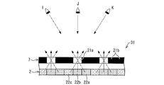
- FIG. 7 is a cross-sectional view showing a state of the liquid crystal display panel 2 and the parallax barrier 7 in the triple view display mode.
- the parallax barrier 7 is provided on the front surface (user side) of the liquid crystal display panel 2 with a slight distance.
- the cell rows 21a in the transmissive state and the cell rows 21b in the non-transmissive state are alternately arranged.
- two non-transparent cell rows 21b are arranged for one transparent cell row 21a.
- a pixel column 22a indicating the first image, a pixel column 22b indicating the second image, and a pixel column 22c indicating the third image are periodically arranged.
- the viewing direction (viewing angle) in which the pixel row 22a indicating the first image can be viewed is limited, the first image is displayed with respect to the direction I in the left diagonal direction, the front direction J and the right diagonal direction.
- the viewing direction in which the pixel row 22b indicating the second image can be viewed is limited, the second image is displayed with respect to the direction J in the front direction, and is displayed with respect to the direction I and the direction K in the oblique direction.
- the viewing direction in which the pixel row 22c indicating the third image can be visually recognized is limited, the third image is displayed with respect to the direction K in the right diagonal direction, the direction J in the front direction, and the direction I in the left diagonal direction. Is not displayed.
- the absolute value of the angle which each direction makes with respect to the display screen is the same for the direction I and the direction K.
- the display mode is set to the triple view display mode, it is assumed that three users view different videos from directions I, J, and K, respectively.
- Gamma table data (gamma table data for direction J) is used to perform gamma correction on the second image in the pixel array 22b.
- Gamma correction is performed on the first image in the pixel row 22a and the third image in the pixel row 22c using the second gamma table data for the triple view display mode (gamma table data for directions I and K).
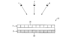
- FIG. 8 is a cross-sectional view showing the state of the liquid crystal display panel 2 and the parallax barrier 7 in the normal display mode.
- the parallax barrier 7 is disabled as in the case of the first embodiment, and each cell 21 of the parallax barrier allows the light of all the pixels 22 of the liquid crystal display panel 2 to be directed in an arbitrary direction. Make it transparent. Therefore, the display device 31 displays one image in an arbitrary direction.
- the display device 31 can display an image with a gamma characteristic suitable for each display mode by switching the gamma correction according to the display mode. That is, the display device 31 can display an image with gamma characteristics suitable for viewing in the viewing direction assumed in each display mode.
- the present invention is not limited to the dual view and triple view, and can be applied to a display device that displays four or more images in different viewing directions.
- FIG. 9 is a block diagram showing a schematic configuration of the display device 32 of the present embodiment.
- the display device 32 includes a liquid crystal display panel 2, a first gate driver 3, a third source driver (gamma correction unit) 16, a first timing signal generation unit 5, a parallax barrier 7, a second gate driver 8, and a second source driver 9. , A second timing signal generation unit 10, a display mode switching unit 11, a parallax barrier control unit 12, and a display control unit 13.
- the display mode switching unit 11 outputs a display mode signal indicating the set mode to the display control unit 13, the parallax barrier control unit 12, and the third source driver 16.
- the display control unit 13 receives an input video signal from the outside of the display device 1, generates video data that has been processed according to the display mode, and outputs the video data to the third source driver 16.
- the third source driver 16 includes a first gamma correction circuit 17a and a second gamma correction circuit 17b.
- the third source driver 16 generates an analog gradation data signal to be output to each pixel from the video data output from the display control unit 13.
- the third source driver 16 sends the data signal to the data signal line connected to the liquid crystal display panel 2 based on the source clock signal (SCK) and the source start pulse (SSP) output from the first timing signal generator 5. Output.
- the third source driver 16 uses the first gamma correction circuit 17a to convert the digital video data received from the display control unit 13 into an analog gradation voltage according to the gradation. Is converted into a data signal indicating.
- the first gamma correction circuit 17a is a D / A converter including a ladder resistor for generating a voltage of each gradation.
- the digital signal indicating the gradation of the pixel is converted into a voltage corresponding to each gradation.
- the third source driver 16 uses the second gamma correction circuit 17b to convert the digital video data received from the display control unit 13 into an analog gradation voltage according to the gradation. Is converted into a data signal indicating.
- the second gamma correction circuit 17b is a D / A converter including a ladder resistor for generating a voltage of each gradation.
- a digital signal indicating the gradation of the pixel is converted into a voltage corresponding to each gradation.
- the first gamma correction circuit 17a and the second gamma correction circuit 17b are different in configuration of the internal ladder resistor, and therefore output different gradation voltages in the intermediate gradation. That is, the first gamma correction circuit 17a and the second gamma correction circuit 17b perform gamma correction at the same time when generating the gradation voltage, but perform different gamma correction.
- the third source driver 16 switches between using the first gamma correction circuit 17a and the second gamma correction circuit 17b according to the display mode.
- a display device is a display device capable of displaying an image with different viewing angle regions, and displays the image in order to solve the above-described problem.
- a gamma correction unit that performs different gamma correction on the image according to the viewing angle region is provided.
- a display device control method is a display device control method capable of displaying an image with different viewing angle regions, and in order to solve the above-described problem, Different gamma corrections are performed on the image depending on the viewing angle region in which the image is displayed.
- an image can be displayed with an appropriate gamma characteristic with respect to the viewing direction in which each image is displayed according to the viewing angle region in which the image is displayed. Therefore, the display device can display an image with an appropriate gamma characteristic with respect to an assumed user direction according to each image.
- the display device includes a display switching unit that switches between the first display state and the second display state, and a viewing angle control unit that controls the viewing angle region of the image displayed according to the display state, In the first display state and the second display state, the viewing angle regions for displaying images are different from each other, and the gamma correction unit is different in the first display state and the second display state according to the display state. It may be configured to perform gamma correction.
- the display device in the first display state, it is possible to display an image with an appropriate gamma characteristic with respect to the first viewing direction in which the image is displayed in the first display state.
- An image can be displayed with an appropriate gamma characteristic with respect to the second viewing direction in which the image is displayed in a second display state different from the one viewing direction. Therefore, the display device can display an image with an appropriate gamma characteristic with respect to an assumed user direction in accordance with each display state.
- the gamma correction unit may have the same gamma characteristic in the first viewing direction in which the image is displayed in the first display state and the gamma characteristic in the second viewing direction in which the image is displayed in the second display state. Gamma correction is performed so that the first viewing direction and the second viewing direction may have different angles with respect to the display screen.
- the gamma characteristic of the first visual field direction in which the image is displayed in the first display state even when the angle of the first visual field direction and the angle of the second visual field direction with respect to the display screen are different from each other, the gamma characteristic of the first visual field direction in which the image is displayed in the first display state. Then, gamma correction can be performed so that the gamma characteristic in the second viewing direction in which the image is displayed in the second display state is the same. Therefore, the user can view the image in the same way (with the same gamma characteristic) both in the first visual field direction in the first display state and in the second visual field direction in the second display state.
- the display device may be configured to display each of a plurality of images with respect to the different viewing angle regions in the first display state, and to display a single image in the second display state. Good.
- the first display state corresponds to the multi-view display mode
- the second display state corresponds to the normal display mode. Therefore, according to the display mode, the display device performs gamma correction so that an appropriate gamma characteristic is obtained in the viewing direction (for example, an oblique direction) assumed in the multi-view display mode in the multi-view display mode. In the display mode, gamma correction can be performed so that an appropriate gamma characteristic is obtained in the viewing direction (for example, the front direction) assumed in the normal display mode.
- the first display state is a 3D display state in which each of a plurality of images is displayed with respect to different viewpoint positions
- the second display state is a 2D display state in which one image is displayed. Also good.
- the user's viewpoint In the 3D display state, the user's viewpoint is fixed (bound) at a predetermined position, but in the 2D display state, the user's viewpoint is not bound.
- the display device performs gamma correction so that an appropriate gamma characteristic is obtained with respect to the position of the predetermined viewpoint according to the display state.
- the display device may include a parallax barrier, and the viewing angle control unit may control the viewing angle region of the displayed image by controlling the parallax barrier.
- the visual field direction of the image displayed by a parallax barrier is restrict
- the display device displays the first image in the first visual field direction, and simultaneously displays the second image in the second visual field direction having a different angle with respect to the display screen from the first visual field direction. May be configured to perform different gamma correction for each of the first image and the second image.
- each image in the multi-view display mode in which the first image and the second image are displayed in the first visual field direction and the second visual field direction, respectively, the angle of the first visual field direction and the second visual field direction with respect to the display screen Are different from each other, gamma correction is performed on each image in accordance with each viewing direction. Therefore, each image can be displayed with an appropriate gamma characteristic in each viewing direction.
- the display device may include a liquid crystal display unit that displays an image.
- liquid crystal display panels have different gamma characteristics depending on the angle with respect to the display screen. Even in such a case, since the display device performs gamma correction according to the display state, it is possible to display an image with an appropriate gamma characteristic with respect to an assumed user direction according to each display state. .
- the present invention can be used for a display device capable of switching between a multi-view display mode or a 3D display mode and a normal display mode.
- Display device 2 Liquid crystal display panel (liquid crystal display unit) 3 First gate driver 4 First source driver 5 First timing signal generator 7 Parallax barrier 8 Second gate driver 9 Second source driver 10 Second timing signal generator 11 Display mode switching unit (display switching unit) 12 Parallax barrier control unit (viewing angle control unit) 13 Display Control Unit 14 Gamma Data Storage Unit 15 Gamma Correction Unit 16 Third Source Driver (Gamma Correction Unit) 17a First gamma correction circuit 17b Second gamma correction circuit
Landscapes
- Engineering & Computer Science (AREA)
- Chemical & Material Sciences (AREA)
- Crystallography & Structural Chemistry (AREA)
- Physics & Mathematics (AREA)
- Computer Hardware Design (AREA)
- General Physics & Mathematics (AREA)
- Theoretical Computer Science (AREA)
- Liquid Crystal Display Device Control (AREA)
- Liquid Crystal (AREA)
Abstract
画像を表示する視野方向が互いに異なる表示モード毎に、その表示モードに適した表示を行う表示装置を実現する。本発明の一態様に係る表示装置(1)は、視認可能な視野角領域を異ならせて画像を表示することができる。デュアルビュー表示モードおよびノーマル表示モードでは画像を表示する視野角領域が互いに異なる。表示装置(1)は、画像を表示する視野角領域に応じて、異なるガンマ補正を行うガンマ補正部(15)を備える。
Description
本発明は、マルチビュー表示モードまたは3D表示モードとノーマル表示モードとを切り替え可能な表示装置に関する。
従来、液晶表示パネル等を用いた表示装置において、表示画面の前面(ユーザ側)に視差バリアを備え、視差バリアによって画像が表示される視野方向を制限して、複数の画像をそれぞれ異なる視野方向に対して視認可能に表示させるマルチビュー表示を行う表示装置がある。特に、2方向(典型的には右斜め方向および左斜め方向)に対して異なる画像を表示する場合をデュアルビュー(2視野方向)表示という。これに対し、視差バリアを用いず、任意の視野方向に対して共通の画像を表示する場合をノーマル表示という。このような表示装置では、液晶等からなる視差バリアの有効/無効を切り替えることにより、マルチビュー表示モードとノーマル表示モードとを切り替えることができる。例えば、2人でそれぞれ異なる映像を見たい場合は、マルチビュー表示モードで左右の視野方向からそれぞれの映像を視聴し、1人で映像を見たい場合は、ノーマル表示モードで正面から映像を視聴するといった使い方ができる。
マルチビュー表示モードとノーマル表示モードとを切り替え可能な表示装置の例が、特許文献1および2に開示されている。
しかしながら、上記従来の構成では、表示画面に対する視野方向の角度(視点の位置)によって液晶表示パネル自体のガンマ特性が異なることが考慮されていない。そのため、ユーザは、マルチビュー表示モードおよびノーマル表示モードのいずれかにおいて、最適な条件で画像を見ることができなかった。
ここで、一般的な液晶表示パネルでは、ある階調の画素を表示画面に対して正面方向から見た場合の輝度と、表示画面に対して斜め方向から見た場合の輝度とが異なる。例えば、ある階調T1の画素を正面方向から見た輝度がL1であるとき、該画素を所定の斜め方向から見た輝度はL1’になる。また、別の階調T2の画素を正面方向から見た輝度がL2であるとき、該画素を所定の斜め方向から見た輝度はL2’になる。ただし、L1およびL2の比と、L2およびL2’の比とは、同じにはならない。すなわち、明るい階調の画素と暗い階調の画素との明るさの比が、正面方向と斜め方向とでは異なって見えてしまう。この現象は中間階調において顕著である。
この問題は、液晶表示パネルのガンマ特性が正面方向と斜め方向とで異なることに起因する。液晶表示パネルの中の各画素の液晶分子は、中間階調の表示状態において、表示画面に対して角度を持って(斜めに)配向する。これによって、バックライトの一部の光を透過し、中間階調を表現する。しかしながら、液晶分子の角度に応じて(階調に応じて)、画素から正面方向に出射される光量と斜め方向に出射される光量との比が異なるため、ガンマ特性が正面方向と斜め方向とで異なってしまう。
例えばテレビジョン等の表示装置では、各階調に対する実際の表示輝度との関係を表すガンマ特性が、γ=2.2に設定される。マルチビュー表示モードとノーマル表示モードとを切り替え可能な表示装置において、マルチビュー表示モードに適したガンマ補正を設定すると、ノーマル表示モード時のガンマ特性が不適切なものになる。例えば、マルチビュー表示モード時の左右の斜め方向から見たガンマ特性がγ=2.2となるようにガンマ補正を行う場合、ノーマル表示モード時に正面方向から見たガンマ特性はγ=2.2から外れたものになってしまう。そのため、表示モードを切り替えて異なる視点から見た場合に、画像の見え方が異なってしまう。
本発明は、上記の問題点に鑑みてなされたものであり、その目的は、画像を表示する視野方向が互いに異なる表示モード毎に、その表示モードに適した表示を行う表示装置を実現することにある。
本発明に係る表示装置は、視認可能な視野角領域を異ならせて画像を表示することが可能な表示装置であって、上記の課題を解決するために、上記画像を表示する上記視野角領域に応じて、異なるガンマ補正を該画像に対して行うガンマ補正部を備えることを特徴としている。
本発明に係る表示装置の制御方法は、視認可能な視野角領域を異ならせて画像を表示することが可能な表示装置の制御方法であって、上記の課題を解決するために、上記画像を表示する上記視野角領域に応じて、異なるガンマ補正を該画像に対して行うことを特徴としている。
上記の構成によれば、画像を表示する視野角領域に応じて、それぞれの画像を表示する視野方向に対して適切なガンマ特性で画像を表示することができる。そのため、上記表示装置は、各画像に応じて、想定されるユーザの方向に対して適切なガンマ特性で画像を表示することができる。
以上のように、本発明に係る表示装置および表示装置の制御方法は、画像を表示する視野角領域に応じて、それぞれの画像を表示する視野方向に対して適切なガンマ特性で画像を表示することができる。
そのため、上記表示装置は、各画像に応じて、想定されるユーザの方向に対して適切なガンマ特性で画像を表示することができる。
[実施形態1]
以下、本発明の一実施形態について、図1~図4に基づいて説明する。
以下、本発明の一実施形態について、図1~図4に基づいて説明する。
図1は、本実施形態の表示装置1の概略構成を示すブロック図である。表示装置1は、液晶表示パネル(液晶表示部)2、第1ゲートドライバ3、第1ソースドライバ4、第1タイミング信号生成部5、視差バリア7、第2ゲートドライバ8、第2ソースドライバ9、第2タイミング信号生成部10、表示モード切替部(表示切替部)11、視差バリア制御部(視野角制御部)12、表示制御部13、ガンマデータ記憶部14、およびガンマ補正部15を備える。
液晶表示パネル2は、表示装置1に入力される映像信号に基づいて、画像の表示を行う。液晶表示パネル2は、図示は省略するが、互いに平行に延びるm本の走査信号線および互いに平行に延びるn本のデータ信号線と、マトリクス状に配置された画素とを有している。画素は、隣接する2本の走査信号線と隣接する2本のデータ信号線とで包囲された領域に形成され、スイッチング素子と、液晶容量とによって構成される。
第1ゲートドライバ3は、第1タイミング信号生成部5から出力されるゲートクロック信号(GCK)およびゲートスタートパルス(GSP)などの各種タイミング信号に基づいて、走査信号線に与える走査信号を順次発生する。この走査信号線は、液晶表示パネル2の各行の画素に接続されている。
第1ソースドライバ4は、ガンマ補正部15から出力される映像データから、各画素に出力するアナログ階調のデータ信号を生成する。第1ソースドライバ4は、ガンマ補正部15から受け取ったデジタルの映像データの階調に応じて、アナログの階調電圧を示すデータ信号に変換する。映像データでは各画素の階調がデジタル信号で表されるが、データ信号では、各画素の階調がその階調に応じた電圧の高さで表される。ここで、第1ソースドライバ4は、液晶表示パネル2の印加電圧-透過率の非線形の特性を考慮して、各階調に応じた電圧に変換する。第1ソースドライバ4は、第1タイミング信号生成部5から出力されるソースクロック信号(SCK)およびソーススタートパルス(SSP)に基づいて、データ信号をデータ信号線に出力する。このデータ信号線は、液晶表示パネル2の各列の画素に接続されている。
第1タイミング信号生成部5は、第1ソースドライバ4に対して、ソースクロック信号(SCK)およびソーススタートパルス(SSP)などのタイミング信号を出力する。また、第1タイミング信号生成部5は、第1ゲートドライバ3に対して、ゲートクロック信号(GCK)およびゲートスタートパルス(GSP)などのタイミング信号を出力する。
視差バリア7は、液晶表示パネル2の前面(ユーザ側)に設けられている。視差バリア7は、図示は省略するが、互いに平行に延びるm’本の走査信号線および互いに平行に延びるn’本のデータ信号線と、マトリクス状に配置されたセルとを有している。このセルは、隣接する2本の走査信号線と隣接する2本のデータ信号線とで包囲された領域に形成され、スイッチング素子と、液晶容量とによって構成される。視差バリア7の各セルは、印加される電圧に応じて、背面の液晶表示パネル2の画素から出射される光を透過するか否かを切り替えることができる。視差バリア7のセル列は、液晶表示パネル2の画素列の間に位置するように配置されている。ノーマル表示モードでは、視差バリア7の全てのセルが背面からの光を透過する。そのため、ノーマル表示モードでは、液晶表示パネル2に表示された画像は、任意の方向から見ることができる。デュアルビュー表示モードでは、視差バリア7のセルをストライプ状に1列おきに透過/不透過にする。そのため、液晶表示パネル2の画像を見ることができる視野方向が画素列毎に制限され、左右の斜めの2つの視野方向に別々の画像が表示される。
第2ゲートドライバ8は、第2タイミング信号生成部10から出力されるゲートクロック信号(GCK)およびゲートスタートパルス(GSP)などの各種タイミング信号に基づいて、走査信号線に与える走査信号を順次発生する。この走査信号線は、視差バリア7の各行のセルに接続されている。
第2ソースドライバ9は、視差バリア制御部12から出力される視差バリアデータに基づいて、各セルに出力する視差バリア信号を生成する。第2ソースドライバ9は、第2タイミング信号生成部10から出力されるソースクロック信号(SCK)およびソーススタートパルス(SSP)に基づいて、視差バリア信号をデータ信号線に出力する。このデータ信号線は、視差バリア7の各列のセルに接続されている。
第2タイミング信号生成部10は、第2ソースドライバ9に対して、ソースクロック信号(SCK)およびソーススタートパルス(SSP)などのタイミング信号を出力する。また、第2タイミング信号生成部10は、第2ゲートドライバ8に対して、ゲートクロック信号(GCK)およびゲートスタートパルス(GSP)などのタイミング信号を出力する。
表示モード切替部11は、ユーザによる表示モードの設定に応じて、ノーマル表示モードとデュアルビュー表示モードとを切り替える。表示モード切替部11は、設定されたモードを示す表示モード信号を、表示制御部13、ガンマ補正部15、および視差バリア制御部12に出力する。なお、ユーザは、リモコン等の入力装置を利用して、表示装置1に表示モードを指定することができる。なお、ユーザが設定するのではなく、表示装置1に入力される映像信号等に基づいて、表示モード切替部11が表示モードを設定してもよい。
視差バリア制御部12は、表示モード切替部11から受け取った表示モード信号に基づいて、ノーマル表示モードであるかデュアルビュー表示モードであるかを判断する。デュアルビュー表示モードである場合、視差バリア制御部12は、視差バリア7のセルをストライプ状に透過/不透過状態にするための視差バリアデータを第2ソースドライバ9に出力する。ノーマル表示モードである場合、視差バリア制御部12は、視差バリア7の全てのセルを透過状態にするための視差バリアデータを第2ソースドライバ9に出力する。なお、ノーマル表示モードである場合は、視差バリア制御部12は、視差バリアデータを第2ソースドライバ9に出力しないようにしてもよい。視差バリアデータが第2ソースドライバ9に入力されない場合、第2ソースドライバ9は、視差バリア7の全てのセルを透過状態にしてもよい。
表示制御部13は、表示装置1の外部から入力映像信号を受け取り、表示モードに応じた処理を施した映像データを生成し、映像データをガンマ補正部15に出力する。ノーマル表示モードでは、全体の画素を使用して1つの画像(映像)を表示する。デュアルビュー表示モードでは、左右用の2つの画像を同時に表示するために、1列おきの画素を使用して各画像を表示する。1つの画像を表示するために使用される画素は、全体の画素の半分となる。そのため、デュアルビュー表示モードでは、表示制御部13は、外部から2つの映像の入力映像信号を受け取り、各フレームについて、ストライプ状に列毎に交互になるよう2つの映像を合成した画像を示す映像データを生成する。表示制御部13は、表示モード切替部11から受け取った表示モード信号に基づいて、ノーマル表示モードであるかデュアルビュー表示モードであるかを判断する。
ガンマデータ記憶部14は、ガンマ補正を行うための、ノーマル表示モードおよびデュアルビュー表示モードのそれぞれに対応したテーブルデータ(LUT)を記憶している。ガンマデータ記憶部14は、ガンマ補正部15の要求に応じて、ノーマル表示モード用の、またはデュアルビュー表示モード用のガンマテーブルデータをガンマ補正部15に出力する。
ガンマ補正部15は、表示モード切替部11から表示モード信号を受け取り、表示モードに応じてガンマデータ記憶部14からその表示モード用のガンマテーブルデータを取得する。ガンマ補正部15は、取得したガンマテーブルデータに応じて、入力された映像データの階調値を変換(ガンマ補正)し、表示モードに応じてガンマ補正された映像データを第1ソースドライバ4に出力する。
図2は、デュアルビュー表示モードにおける液晶表示パネル2および視差バリア7の状態を示す断面図である。液晶表示パネル2の前面(ユーザ側)に視差バリア7が設けられている。
デュアルビュー表示モードの場合、視差バリア7において、透過状態のセル列21aと不透過状態のセル列21bとが交互に並んでいる。また、液晶表示パネル2において、第1画像を示す画素列22aと第2画像を示す画素列22bとが交互に並んでいる。透過状態のセル列21aと、画素列22a・22bの配置がずれているため、第1画像を示す画素列22aを視認可能な視野方向(視野角領域)が制限され、第1画像は左斜め方向の方向Aに対して表示され、右斜め方向の方向Bに対しては表示されない。また同様に、第2画像を示す画素列22bを視認可能な視野方向が制限され、第2画像は右斜め方向の方向Bに対して表示され、左斜め方向の方向Aに対しては表示されない。なお、方向Aと方向Bとについて、各方向が表示画面に対してなす角の絶対値は同じである。ユーザが表示モードをデュアルビュー表示モードに設定している場合、2人のユーザがそれぞれ方向Aおよび方向Bから別々の映像を視聴することが想定される。なお、デュアルビュー表示モードのときに、正面から表示画面を見ると、第1画像および第2画像のクロストークが発生し、いずれの画像も正しく見ることができない。すなわち、デュアルビュー表示モードでは、正面の方向は、第1画像および第2画像が表示されない方向と言える。
図3は、ノーマル表示モードにおける液晶表示パネル2および視差バリア7の状態を示す断面図である。
ノーマル表示モードの場合、視差バリア7が無効に設定されており、視差バリアの各セル21は、液晶表示パネル2の全ての画素22の光を任意の方向に透過させる。そのため、表示装置1は、任意の視点の方向に対して1つの(共通の)画像を表示する。ユーザが表示モードをノーマル表示モードに設定している場合、ユーザが表示画面の正面方向にある方向Cから視聴することが想定される。
ここで、上述した従来の構成のように、表示モードに応じてガンマ補正が変わらない場合、上述した問題が発生する。すなわち、デュアルビュー表示モードにおける視聴を優先して、斜め方向の方向Aおよび方向Bから見た時のガンマ特性が、所望の値(例えばγ=2.2)になるように設定されている場合、正面方向の方向Cから見た時のガンマ特性は、上記所望の値からずれた値(例えばγ=1.8)になってしまう。
図4は、従来の構成での、2つの視野方向(正面方向、斜め方向)におけるガンマ特性を表すグラフである。横軸は、画素の階調を示す。RGBの1つの色の画素の階調は、256階調である。縦軸は、2つの視野方向(正面方向、斜め方向)において観測されるその画素の輝度を示す。なお、輝度の値は最大輝度に合わせて正規化している。従来の構成では、表示モードに応じてガンマ補正が変わらないので、斜め方向の方向Aおよび方向Bから見た時のガンマ特性(γ=2.2)と、正面方向の方向Cから見た時のガンマ特性(γ=1.8)とが異なるものになってしまう。なお、斜め方向から見たときのガンマ特性に比べて、正面方向から見たときのガンマ特性が大きくなるか小さくなるかは、液晶の構造および材料等によって変わる。
本実施の形態では、ガンマ補正部15は、デュアルビュー表示モードにおいては、斜めの視野方向(方向A、B)におけるガンマ特性が所望の値(γ=2.2)になるように、デュアルビュー表示モード用のガンマテーブルデータを使用してガンマ補正を行う。また、ガンマ補正部15は、ノーマル表示モードにおいては、正面の視野方向(方向C)におけるガンマ特性が所望の値(γ=2.2)になるように、ノーマル表示モード用のガンマテーブルデータを使用してガンマ補正を行う。このように、表示装置1は、表示モードに合わせてガンマ補正を切り替えることにより、各表示モードに適したガンマ特性で画像を表示することができる。すなわち、表示装置1は、各表示モードで想定される視野方向における視聴に適したガンマ特性で画像を表示することができる。
なお、デュアルビュー表示モードでは、1つの画像は全体の半分の画素によって表現される。そのため、一般に、デュアルビュー表示モードでは、ノーマル表示モードに比べて画像全体としての輝度が低下する。表示装置1は、デュアルビュー表示モードにおいて、バックライト(図示せず)の出力輝度をノーマル表示モードにおける出力輝度よりも大きくする。これにより、表示モードを切り替えたときの、見た目の明るさの差を小さくすることができる。なお、バックライトの出力輝度を大きくしても、各画素の輝度が一律に明るくなるだけなので、ガンマ特性には影響しない。
<変形例>
なお、液晶表示パネル2自体のガンマ特性は、厳密にはRGBの色毎に異なりうるので、各表示モードについてあらかじめ各色のガンマテーブルデータを用意し、RGB毎に異なるガンマ補正を行ってもよい。
なお、液晶表示パネル2自体のガンマ特性は、厳密にはRGBの色毎に異なりうるので、各表示モードについてあらかじめ各色のガンマテーブルデータを用意し、RGB毎に異なるガンマ補正を行ってもよい。
また、ユーザがそれぞれの表示モードにおけるガンマ特性を設定できるようにしてもよい。この場合、ガンマデータ記憶部14は、各表示モードに対して設定されたガンマ特性に合うガンマテーブルデータを生成し、記憶しておく。
また、方向Aおよび方向Bの表示画面に対する角度(の絶対値)が異なる場合(例えば方向Aの表示画面に対する角度が60°、方向Bの表示画面に対する角度が45°の場合)、方向Aと方向Bとで、液晶表示パネル2自体のガンマ特性が異なる。この場合、ガンマ補正部15は、視野方向Aに対して表示される第1画像について、方向Aにおけるガンマ特性が所望の値(γ=2.2)になるように、方向A用のガンマテーブルデータを用いて第1画像に対してガンマ補正を行い、視野方向Bに対して表示される第2画像について、方向Bにおけるガンマ特性が所望の値(γ=2.2)になるように、方向B用のガンマテーブルデータを用いて第2画像に対してガンマ補正を行ってもよい。これにより、デュアルビュー表示モードにおいて、異なる視野方向A、Bに対して表示する2つの画像について、各視野方向におけるガンマ特性が最適になるようにガンマ補正を行うことができる。なお、例えばデュアルビュー表示モードにおける各視野方向に、3D画像を表示させてもよい(デュアルビュー3D表示モード)。例えばさらに応用して、デュアルビュー2D表示モードとデュアルビュー3D表示モードとを切り替えて、デュアルビュー2D表示モードおよびデュアルビュー3D表示モードのいずれであるかに応じて、異なるガンマ補正を行ってもよい。
なお、方向Aおよび方向Bの表示画面に対する角度(の絶対値)が同じ場合であっても、第1画像の方向Aのガンマ特性と、第2画像の方向Bのガンマ特性とが異なる値になるように、第1画像および第2画像に対して異なるガンマ補正を行ってもよい。
実施形態1では、デュアルビュー表示モードとノーマル表示モードとにおいて、異なる視野方向(斜め方向、正面方向)のガンマ特性が、同じ所望の値(γ=2.2)になるようにガンマ補正を行う場合について説明したが、これに限らない。例えば、表示モードに応じてバックライトの出力輝度を変えない場合、デュアルビュー表示モードではノーマル表示モードに比べて画像が全体的に暗くなる。画面の全体的な明るさが低い場合、中間階調の画素の輝度を意図的に大きくする方が、人間の視覚にとって好ましい場合がある。よって、ノーマル表示モードでは正面の視野方向(方向C)におけるガンマ特性がγ=2.2になるようにガンマ補正を行い、デュアルビュー表示モードでは斜めの視野方向(方向A、B)におけるガンマ特性がγ=2.0になるようにガンマ補正を行うようにしてもよい。
なお、例えば、第1ソースドライバ4で行うデジタル(階調)-アナログ(電圧)の変換に、一方の表示モードでのガンマ補正を含ませてもよい。例えば、ノーマル表示モードでは、ガンマ補正部15は、映像データのガンマ補正を行わず、表示制御部13から入力された映像データを第1ソースドライバ4に出力する。第1ソースドライバ4は、映像データが示す各階調に対して、正面方向のガンマ特性がγ=2.2になるように、液晶表示パネル2の印加電圧-透過率の非線形の特性を考慮した電圧を出力する。デュアルビュー表示モードでは、ガンマ補正部15が、映像データのガンマ補正を行い、第1ソースドライバ4が、ガンマ補正された映像データに対して、ノーマル表示モードと同様の処理を行って電圧を出力する。すなわち、デュアルビュー表示モードでは、ガンマ補正部15および第1ソースドライバ4で補正された結果、第1ソースドライバ4から最終的に斜めの視野方向のガンマ特性がγ=2.2となるような電圧が液晶表示パネル2に出力される。
なお、本発明は、液晶表示パネルに限らず、視野方向に応じてガンマ特性が変化する表示パネルを備え、第1表示状態と第2表示状態とで画像を表示する視野方向を切り替え可能な表示装置に適用可能である。例えば視差バリアを用いず、バックライトの指向性を制御することでデュアルビュー表示を実現する表示装置にも適用することができる。例えば、MEMS(Micro Electro Mechanical Systems)ディスプレイにも適用可能である。
[実施形態2]
本発明の他の実施形態について、以下に説明する。なお、説明の便宜上、実施形態1にて説明した図面と同じ機能を有する部材・構成については、同じ符号を付記し、その詳細な説明を省略する。本実施形態では、特別な眼鏡等を必要とせず、2つの画像を表示する視野角を制限し、3D表示が可能な表示装置の場合について説明する。
本発明の他の実施形態について、以下に説明する。なお、説明の便宜上、実施形態1にて説明した図面と同じ機能を有する部材・構成については、同じ符号を付記し、その詳細な説明を省略する。本実施形態では、特別な眼鏡等を必要とせず、2つの画像を表示する視野角を制限し、3D表示が可能な表示装置の場合について説明する。
なお、本実施形態の表示装置の基本的な機能構成は、図1に示す構成と同じである。表示モード切替部11は、ユーザの指示に応じて、または、表示装置に入力される映像信号等に基づいて、2D表示モードと3D表示モードとを切り替える。2D表示モードの場合、液晶表示パネル2は、全ての画素で1つの画像を表示する。3D表示モードの場合、液晶表示パネル2は、画素の1列おきに左右用の画像を交互に表示する。
図5は、3D表示モードにおける液晶表示パネル2および視差バリア7の状態を示す断面図である。本実施形態の表示装置30では、液晶表示パネル2の前面(ユーザ側)に、少し距離を空けて視差バリア7が設けられている。
3D表示モードのときは、デュアルビュー表示モードのときと同様に、視差バリア7において、透過状態のセル列21aと不透過状態のセル列21bとが交互に並んでいる。これにより、各画素列から出射される光の方向が制限され、各画素列を視認可能な視野方向(視野角)が制限される。例えば、右眼用の第1画像を表示する各画素列22aから視差バリア7を通過して出た光は、所定の視点Dに向かって進む。また、左眼用の第2画像を表示する各画素列22bから視差バリア7を通過して出た光は、所定の視点Eに向かって進む。視差バリア7によって、視点Dからは、左眼用の第2画像を表示する画素22bは視認することができず、視点Eからは、右眼用の第1画像を表示する画素22aは視認することができない。なお、図5では簡略化して描いているが、所定の視点D・Eと液晶表示パネル2等との距離は図示するものより大きい。また、表示画面の各位置の画素から視点Dまたは視点Eに光を透過させるために、視差バリアのストライプの間隔は、表示画面の水平位置によって異なる。
3D表示モードでは、このように、左右の目に異なる画像を視認させて、3D表示を行う。ただし、3D画像を視認するために、ユーザの左右の眼が所定の位置(範囲)にあることが前提となる。例えば、表示画面の正面の所定の距離離れた位置において、ユーザは正しく3D画像を視認することができる。所定の位置は、表示装置30の視差バリアの配置に応じて異なる。よって、表示モードが3D表示モードに設定されている場合、1人のユーザの左右の眼がそれぞれ視点Eおよび視点Dに位置する状態で映像を視聴することが想定される。
ガンマ補正部15は、3D表示モードにおいては、正面の所定の視点の方向(視点D、Eの方向)におけるガンマ特性が所望の値(γ=2.2)になるように、3D表示モード用のガンマテーブルデータを使用してガンマ補正を行う。
このとき、例えば右眼用の第1画像を表示する各画素22aから視点Dへの方向(表示画面に対する角度)は、画素22aの位置(水平位置)によって少しだけ異なる。そのため、ガンマ補正部15は、各画素の位置を考慮して、すなわち各画素に応じた所定の視野方向を考慮して、各画素から所定の視点(視点D、E)の視野方向におけるガンマ特性が所望の値になるように、映像データの各画素の階調のガンマ補正を行う。そのため、3D表示モード用のガンマテーブルデータを、各画素の位置(各画素列の位置)に応じて複数用意してもよい。
図6は、2D表示モードにおける液晶表示パネル2および視差バリア7の状態を示す断面図である。
2D表示モードの場合、実施形態1のノーマル表示モードと同様に、視差バリア7が無効に設定されており、視差バリアの各セル21は、液晶表示パネル2の全ての画素22の光を任意の方向に透過させる。そのため、表示装置30は、任意の視点の方向に対して1つの画像を表示する。表示モードが3D表示モードに設定されている場合は、ユーザの両目の視点が表示画面の正面方向の所定の位置(視点D、E)に固定される。一方、表示モードが2D表示モードに設定されている場合、ユーザの視点は束縛されないので、表示画面の画像は任意の方向(例えば図6に示す方向F、G、H等)から視聴されることが想定される。また、複数のユーザによって、同時に異なる方向から視聴されることが想定される。
そのため、2D表示モードにおいては、正面方向(方向F)から見ても斜め方向(方向G、H)から見てもよいように、実施形態1におけるデュアルビュー表示モードとノーマル表示モードとの中間のガンマ補正を行うことが考えられる。よって、本実施形態では、ガンマ補正部15は、2D表示モードにおいては、例えば正面の方向Fと斜めの方向Gとの間の視野方向において、所望のガンマ特性(γ=2.2)になるように、2D表示モード用のガンマテーブルデータを使用してガンマ補正を行う。このとき、例えば正面の視野方向(方向F)におけるガンマ特性はγ=2.0になり、斜めの視野方向(方向G、H)におけるガンマ特性はγ=2.4になる。2D表示モードにおいては、ユーザの視点が拘束されないので、ユーザは任意の方向から自由に表示画面を見ることができ、そのようなユーザに対して適度なガンマ特性で画像(映像)を視聴させることができる。
このように、表示装置30は、3D/2Dの表示モードに合わせてガンマ補正を切り替えることにより、各表示モードに適したガンマ特性で画像を表示することができる。すなわち、表示装置30は、各表示モードで想定される視点または視野方向における視聴に適したガンマ特性で画像を表示することができる。
[実施形態3]
本発明の他の実施形態について、以下に説明する。なお、説明の便宜上、実施形態1にて説明した図面と同じ機能を有する部材・構成については、同じ符号を付記し、その詳細な説明を省略する。本実施形態では、3つの視野方向のそれぞれに異なる3つの画像を表示するマルチビュー(トリプルビュー)表示が可能な表示装置の場合について説明する。
本発明の他の実施形態について、以下に説明する。なお、説明の便宜上、実施形態1にて説明した図面と同じ機能を有する部材・構成については、同じ符号を付記し、その詳細な説明を省略する。本実施形態では、3つの視野方向のそれぞれに異なる3つの画像を表示するマルチビュー(トリプルビュー)表示が可能な表示装置の場合について説明する。
なお、本実施形態の表示装置の基本的な機能構成は、図1に示す構成と同じである。表示モード切替部11は、ユーザの指示に応じて、または、表示装置に入力される映像信号等に基づいて、トリプルビュー表示モードとノーマル表示モードとを切り替える。ノーマル表示モードの場合、液晶表示パネル2は、全ての画素で1つの画像を表示する。トリプルビュー表示モードの場合、液晶表示パネル2には、第1画像を表示する画素列、第2画像を表示する画素列、および第3画像を表示する画素列が周期的に並ぶ。
図7は、トリプルビュー表示モードにおける液晶表示パネル2および視差バリア7の状態を示す断面図である。本実施形態の表示装置31では、液晶表示パネル2の前面(ユーザ側)に、少し距離を空けて視差バリア7が設けられている。
トリプルビュー表示モードのときは、視差バリア7において、透過状態のセル列21aと不透過状態のセル列21bとが交互に並んでいる。ただし、図7に示すように、1つの透過状態のセル列21aに対し、2つの不透過状態のセル列21bが配置されている。また、液晶表示パネル2において、第1画像を示す画素列22aと第2画像を示す画素列22bと第3画像を示す画素列22cとが周期的に並んでいる。これにより、第1画像を示す画素列22aを視認可能な視野方向(視野角)が制限され、第1画像は左斜め方向の方向Iに対して表示され、正面方向の方向Jおよび右斜め方向の方向Kに対しては表示されない。また同様に、第2画像を示す画素列22bを視認可能な視野方向が制限され、第2画像は正面方向の方向Jに対して表示され、斜め方向の方向Iおよび方向Kに対しては表示されない。また同様に、第3画像を示す画素列22cを視認可能な視野方向が制限され、第3画像は右斜め方向の方向Kに対して表示され、正面方向の方向Jおよび左斜め方向の方向Iに対しては表示されない。なお、方向Iと方向Kとについて、各方向が表示画面に対してなす角の絶対値は同じである。
表示モードがトリプルビュー表示モードに設定されている場合、3人のユーザがそれぞれ方向I、方向J、および方向Kから別々の映像を視聴することが想定される。
ガンマ補正部15は、トリプルビュー表示モードにおいては、第2画像の正面方向(方向J)におけるガンマ特性が所望の値(γ=2.2)になるように、トリプルビュー表示モード用の第1のガンマテーブルデータ(方向J用のガンマテーブルデータ)を使用して、画素列22bの第2画像に対してガンマ補正を行う。また、ガンマ補正部15は、トリプルビュー表示モードにおいては、第1画像および第3画像の斜め方向(方向I、K)におけるガンマ特性が所望の値(γ=2.2)になるように、トリプルビュー表示モード用の第2のガンマテーブルデータ(方向I・K用のガンマテーブルデータ)を使用して、画素列22aの第1画像および画素列22cの第3画像に対してガンマ補正を行う。
図8は、ノーマル表示モードにおける液晶表示パネル2および視差バリア7の状態を示す断面図である。
ノーマル表示モードの場合、実施形態1の場合と同様に、視差バリア7が無効に設定されており、視差バリアの各セル21は、液晶表示パネル2の全ての画素22の光を任意の方向に透過させる。そのため、表示装置31は、任意の方向に対して1つの画像を表示する。
ガンマ補正部15は、ノーマル表示モードにおいては、正面の視野方向(方向J)におけるガンマ特性が所望の値(γ=2.2)になるように、ノーマル表示モード用のガンマテーブルデータを使用して、映像データの各画素の階調のガンマ補正を行う。
このように、表示装置31は、表示モードに合わせてガンマ補正を切り替えることにより、各表示モードに適したガンマ特性で画像を表示することができる。すなわち、表示装置31は、各表示モードで想定される視野方向における視聴に適したガンマ特性で画像を表示することができる。
なお、ガンマ補正部15は、ノーマル表示モードにおいて、実施形態2の2D表示モードのように、正面の方向Jと斜めの方向Iとの間の方向でガンマ特性が所望の値(γ=2.2)になるように、ガンマ補正を行ってもよい。
なお、本発明は、デュアルビュー、トリプルビューに限らず、4つ以上の画像をそれぞれ別の視野方向に表示させる表示装置にも適用することができる。
[実施形態4]
本発明の他の実施形態について、以下に説明する。なお、説明の便宜上、実施形態1にて説明した図面と同じ機能を有する部材・構成については、同じ符号を付記し、その詳細な説明を省略する。本実施形態では、実施形態1と同様に、デュアルビュー表示モードとノーマル表示モードとを切り替え可能な表示装置について説明する。本実施形態では、デジタルの映像信号をアナログの階調電圧に変換する際に、ガンマ補正を行う。
本発明の他の実施形態について、以下に説明する。なお、説明の便宜上、実施形態1にて説明した図面と同じ機能を有する部材・構成については、同じ符号を付記し、その詳細な説明を省略する。本実施形態では、実施形態1と同様に、デュアルビュー表示モードとノーマル表示モードとを切り替え可能な表示装置について説明する。本実施形態では、デジタルの映像信号をアナログの階調電圧に変換する際に、ガンマ補正を行う。
図9は、本実施形態の表示装置32の概略構成を示すブロック図である。表示装置32は、液晶表示パネル2、第1ゲートドライバ3、第3ソースドライバ(ガンマ補正部)16、第1タイミング信号生成部5、視差バリア7、第2ゲートドライバ8、第2ソースドライバ9、第2タイミング信号生成部10、表示モード切替部11、視差バリア制御部12、および表示制御部13を備える。
表示モード切替部11は、設定されたモードを示す表示モード信号を、表示制御部13、視差バリア制御部12、および第3ソースドライバ16に出力する。
表示制御部13は、表示装置1の外部から入力映像信号を受け取り、表示モードに応じた処理を施した映像データを生成し、映像データを第3ソースドライバ16に出力する。
第3ソースドライバ16は、第1ガンマ補正回路17aおよび第2ガンマ補正回路17bを備える。第3ソースドライバ16は、表示制御部13から出力される映像データから、各画素に出力するアナログ階調のデータ信号を生成する。第3ソースドライバ16は、第1タイミング信号生成部5から出力されるソースクロック信号(SCK)およびソーススタートパルス(SSP)に基づいて、データ信号を液晶表示パネル2に接続されたデータ信号線に出力する。
デュアルビュー表示モードの場合、第3ソースドライバ16は、第1ガンマ補正回路17aを使用して、表示制御部13から受け取ったデジタルの映像データを、その階調に応じて、アナログの階調電圧を示すデータ信号に変換する。
第1ガンマ補正回路17aは、各階調の電圧を生成するためのラダー抵抗を含む、D/A変換器である。第1ガンマ補正回路17aは、表示画面の斜め方向(図2における方向A、B)におけるガンマ特性が所望の値(γ=2.2)になるように、液晶表示パネル2の印加電圧-透過率の非線形の特性を考慮して、画素の階調を示すデジタル信号を各階調に応じた電圧に変換する。
一方、ノーマル表示モードの場合、第3ソースドライバ16は、第2ガンマ補正回路17bを使用して、表示制御部13から受け取ったデジタルの映像データをその階調に応じて、アナログの階調電圧を示すデータ信号に変換する。
第2ガンマ補正回路17bは、各階調の電圧を生成するためのラダー抵抗を含む、D/A変換器である。第2ガンマ補正回路17bは、表示画面の正面方向(図3における方向C)においてガンマ特性が所望の値(γ=2.2)になるように、液晶表示パネル2の印加電圧-透過率の非線形の特性を考慮して、画素の階調を示すデジタル信号を各階調に応じた電圧に変換する。
第1ガンマ補正回路17aと第2ガンマ補正回路17bとは、内部のラダー抵抗の構成が異なるため、中間階調において互いに異なる階調電圧を出力する。すなわち、第1ガンマ補正回路17aおよび第2ガンマ補正回路17bは、階調電圧を生成する際にガンマ補正も同時に行うが、異なるガンマ補正を行う。第3ソースドライバ16は、表示モードに応じて、第1ガンマ補正回路17aおよび第2ガンマ補正回路17bのいずれを使用するかを切り替える。
本実施の形態では、LUTを使用してデジタルでガンマ補正を行う必要がなく、階調電圧を生成する際にガンマ補正も合わせて行うことができる。
[変形例]
本発明の一態様に係る表示装置は、視認可能な視野角領域を異ならせて画像を表示することが可能な表示装置であって、上記の課題を解決するために、上記画像を表示する上記視野角領域に応じて、異なるガンマ補正を該画像に対して行うガンマ補正部を備える。
本発明の一態様に係る表示装置は、視認可能な視野角領域を異ならせて画像を表示することが可能な表示装置であって、上記の課題を解決するために、上記画像を表示する上記視野角領域に応じて、異なるガンマ補正を該画像に対して行うガンマ補正部を備える。
本発明の一態様に係る表示装置の制御方法は、視認可能な視野角領域を異ならせて画像を表示することが可能な表示装置の制御方法であって、上記の課題を解決するために、上記画像を表示する上記視野角領域に応じて、異なるガンマ補正を該画像に対して行う。
上記の構成によれば、画像を表示する視野角領域に応じて、それぞれの画像を表示する視野方向に対して適切なガンマ特性で画像を表示することができる。そのため、上記表示装置は、各画像に応じて、想定されるユーザの方向に対して適切なガンマ特性で画像を表示することができる。
また、上記表示装置は、第1表示状態および第2表示状態を切り替える表示切替部と、上記表示状態に応じて表示される画像の上記視野角領域を制御する視野角制御部とを備え、上記第1表示状態および上記第2表示状態では画像を表示する上記視野角領域が互いに異なり、上記ガンマ補正部は、上記第1表示状態と上記第2表示状態とにおいて、該表示状態に応じて異なるガンマ補正を行う構成であってもよい。
上記の構成によれば、第1表示状態では、第1表示状態において画像を表示する第1視野方向に対して、適切なガンマ特性で画像を表示することができ、第2表示状態では、第1視野方向とは異なる第2表示状態において画像を表示する第2視野方向に対して、適切なガンマ特性で画像を表示することができる。そのため、上記表示装置は、各表示状態に応じて、想定されるユーザの方向に対して適切なガンマ特性で画像を表示することができる。
また、上記ガンマ補正部は、上記第1表示状態において画像が表示される第1視野方向におけるガンマ特性と、上記第2表示状態において画像が表示される第2視野方向におけるガンマ特性とが同じになるようにガンマ補正を行い、上記第1視野方向と上記第2視野方向とは、表示画面に対する角度が互いに異なる構成であってもよい。
上記の構成によれば、表示画面に対する第1視野方向の角度と第2視野方向の角度とが互いに異なっている場合においても、第1表示状態において画像が表示される第1視野方向のガンマ特性と、第2表示状態において画像が表示される第2視野方向のガンマ特性とが同じになるようにガンマ補正を行うことができる。よって、ユーザは、第1表示状態の第1視野方向においても、第2表示状態の第2視野方向においても同じように(同じガンマ特性で)画像を見ることができる。
また、上記表示装置は、上記第1表示状態では、複数の画像のそれぞれを異なる上記視野角領域に対して表示し、上記第2表示状態では、単一の画像を表示する構成であってもよい。
上記の構成によれば、第1表示状態はマルチビュー表示モードに対応し、第2表示状態はノーマル表示モードに対応する。よって、上記表示装置は、表示モードに応じて、マルチビュー表示モードの場合は、マルチビュー表示モードで想定される視聴方向(例えば斜め方向)において適切なガンマ特性になるようガンマ補正を行い、ノーマル表示モードの場合は、ノーマル表示モードで想定される視聴方向(例えば正面方向)において適切なガンマ特性になるようガンマ補正を行うことができる。
また、上記第1表示状態は、複数の画像のそれぞれを異なる視点位置の方向に対して表示する3D表示状態であり、上記第2表示状態は、1つの画像を表示する2D表示状態であってもよい。
3D表示状態では、ユーザの視点が所定の位置に固定(束縛)されるが、2D表示状態では、ユーザの視点は束縛されない。
上記の構成によれば、上記表示装置は、表示状態に応じて、3D表示状態の場合は、所定の視点の位置に対して適切なガンマ特性になるようガンマ補正を行い、2D表示状態の場合は、その他の視聴方向において適切なガンマ特性になるようガンマ補正を行うことができる。
また、上記表示装置は、視差バリアを備え、上記視野角制御部は、上記視差バリアを制御することにより、表示される画像の上記視野角領域を制御する構成であってもよい。
上記の構成によれば、視差バリアによって表示される画像の視野方向を制限し、第1表示状態および第2表示状態における画像を視認可能な視野方向の状態(画像の視野角の状態)を異ならせることができる。
また、上記表示装置は、第1視野方向に第1画像を表示し、同時に、上記第1視野方向とは表示画面に対する角度が異なる第2視野方向に第2画像を表示し、上記ガンマ補正部は、上記第1画像および上記第2画像のそれぞれについて、異なるガンマ補正を行う構成であってもよい。
上記の構成によれば、第1画像および第2画像をそれぞれ第1視野方向および第2視野方向に表示するマルチビュー表示モードにおいて、表示画面に対する第1視野方向の角度と第2視野方向の角度とが異なる場合であっても、それぞれの視野方向に応じて各画像にガンマ補正を行う。そのため、それぞれの視野方向において、適切なガンマ特性でそれぞれの画像を表示することができる。
また、上記表示装置は、画像を表示する液晶表示部を備える構成であってもよい。
一般に、液晶表示パネルは、表示画面に対する角度に応じてガンマ特性が異なる。このような場合でも、上記表示装置は、表示状態に応じてガンマ補正を行うため、各表示状態に応じて、想定されるユーザの方向に対して適切なガンマ特性で画像を表示することができる。
本発明は上述した各実施形態に限定されるものではなく、請求項に示した範囲で種々の変更が可能であり、異なる実施形態にそれぞれ開示された技術的手段を適宜組み合わせて得られる実施形態についても本発明の技術的範囲に含まれる。
本発明は、マルチビュー表示モードまたは3D表示モードとノーマル表示モードとを切り替え可能な表示装置に利用することができる。
1、30、31、32 表示装置
2 液晶表示パネル(液晶表示部)
3 第1ゲートドライバ
4 第1ソースドライバ
5 第1タイミング信号生成部
7 視差バリア
8 第2ゲートドライバ
9 第2ソースドライバ
10 第2タイミング信号生成部
11 表示モード切替部(表示切替部)
12 視差バリア制御部(視野角制御部)
13 表示制御部
14 ガンマデータ記憶部
15 ガンマ補正部
16 第3ソースドライバ(ガンマ補正部)
17a 第1ガンマ補正回路
17b 第2ガンマ補正回路
2 液晶表示パネル(液晶表示部)
3 第1ゲートドライバ
4 第1ソースドライバ
5 第1タイミング信号生成部
7 視差バリア
8 第2ゲートドライバ
9 第2ソースドライバ
10 第2タイミング信号生成部
11 表示モード切替部(表示切替部)
12 視差バリア制御部(視野角制御部)
13 表示制御部
14 ガンマデータ記憶部
15 ガンマ補正部
16 第3ソースドライバ(ガンマ補正部)
17a 第1ガンマ補正回路
17b 第2ガンマ補正回路
Claims (9)
- 視認可能な視野角領域を異ならせて画像を表示することが可能な表示装置であって、
上記画像を表示する上記視野角領域に応じて、異なるガンマ補正を該画像に対して行うガンマ補正部を備えることを特徴とする表示装置。 - 第1表示状態および第2表示状態を切り替える表示切替部と、
上記表示状態に応じて表示される画像の上記視野角領域を制御する視野角制御部とを備え、
上記第1表示状態および上記第2表示状態では画像を表示する上記視野角領域が互いに異なり、
上記ガンマ補正部は、上記第1表示状態と上記第2表示状態とにおいて、該表示状態に応じて異なるガンマ補正を行うことを特徴とする請求項1に記載の表示装置。 - 上記ガンマ補正部は、上記第1表示状態において画像が表示される第1視野方向におけるガンマ特性と、上記第2表示状態において画像が表示される第2視野方向におけるガンマ特性とが同じになるようにガンマ補正を行い、
上記第1視野方向と上記第2視野方向とは、表示画面に対する角度が互いに異なることを特徴とする請求項2に記載の表示装置。 - 上記第1表示状態では、複数の画像のそれぞれを異なる上記視野角領域に対して表示し、
上記第2表示状態では、単一の画像を表示することを特徴とする請求項2または3に記載の表示装置。 - 上記第1表示状態は、複数の画像のそれぞれを異なる視点位置の方向に対して表示する3D表示状態であり、
上記第2表示状態は、1つの画像を表示する2D表示状態であることを特徴とする請求項2または3に記載の表示装置。 - 視差バリアを備え、
上記視野角制御部は、上記視差バリアを制御することにより、表示される画像の上記視野角領域を制御することを特徴とする請求項2から5のいずれか一項に記載の表示装置。 - 第1視野方向に第1画像が表示され、同時に、上記第1視野方向とは表示画面に対する角度が異なる第2視野方向に第2画像が表示され、
上記ガンマ補正部は、上記第1画像および上記第2画像のそれぞれについて、異なるガンマ補正を行うことを特徴とする請求項1に記載の表示装置。 - 画像を表示する液晶表示部を備えることを特徴とする請求項1から7のいずれか一項に記載の表示装置。
- 視認可能な視野角領域を異ならせて画像を表示することが可能な表示装置の制御方法であって、
上記画像を表示する上記視野角領域に応じて、異なるガンマ補正を該画像に対して行うことを特徴とする表示装置の制御方法。
Applications Claiming Priority (2)
| Application Number | Priority Date | Filing Date | Title |
|---|---|---|---|
| JP2011-096581 | 2011-04-22 | ||
| JP2011096581 | 2011-04-22 |
Publications (1)
| Publication Number | Publication Date |
|---|---|
| WO2012144470A1 true WO2012144470A1 (ja) | 2012-10-26 |
Family
ID=47041576
Family Applications (1)
| Application Number | Title | Priority Date | Filing Date |
|---|---|---|---|
| PCT/JP2012/060290 Ceased WO2012144470A1 (ja) | 2011-04-22 | 2012-04-16 | 表示装置、および制御方法 |
Country Status (1)
| Country | Link |
|---|---|
| WO (1) | WO2012144470A1 (ja) |
Citations (2)
| Publication number | Priority date | Publication date | Assignee | Title |
|---|---|---|---|---|
| JP2009151016A (ja) * | 2007-12-19 | 2009-07-09 | Toshiba Matsushita Display Technology Co Ltd | 液晶表示装置 |
| WO2010038310A1 (ja) * | 2008-10-03 | 2010-04-08 | Necディスプレイソリューションズ株式会社 | 画像補正システム、表示装置、補正処理回路、及び、画像補正方法 |
-
2012
- 2012-04-16 WO PCT/JP2012/060290 patent/WO2012144470A1/ja not_active Ceased
Patent Citations (2)
| Publication number | Priority date | Publication date | Assignee | Title |
|---|---|---|---|---|
| JP2009151016A (ja) * | 2007-12-19 | 2009-07-09 | Toshiba Matsushita Display Technology Co Ltd | 液晶表示装置 |
| WO2010038310A1 (ja) * | 2008-10-03 | 2010-04-08 | Necディスプレイソリューションズ株式会社 | 画像補正システム、表示装置、補正処理回路、及び、画像補正方法 |
Similar Documents
| Publication | Publication Date | Title |
|---|---|---|
| CN102547335B (zh) | 立体图像显示器及其驱动方法 | |
| TWI476753B (zh) | 處理用於顯示於包含多原色圖像顯示面板之顯示裝置之圖像資料之方法 | |
| CN102244797B (zh) | 立体图像显示器和驱动该立体图像显示器的方法 | |
| CN102572495B (zh) | 具有图案化延迟器的立体显示设备及其驱动方法 | |
| CN102341744B (zh) | 立体显示装置 | |
| US9191657B2 (en) | Image display device | |
| JP2011076034A (ja) | 画像表示装置およびその駆動方法 | |
| WO2014203366A1 (ja) | 画像処理装置、方法、及びプログラム、並びに画像表示装置 | |
| US9116357B2 (en) | Hybrid multiplexed 3D display and displaying method thereof | |
| CN102187382A (zh) | 图像显示系统、图像显示设备和光学快门 | |
| US9666118B2 (en) | Transparent display apparatus | |
| JP2013073238A (ja) | 立体映像表示装置及び方法 | |
| TWI422863B (zh) | 立體顯示裝置 | |
| US9019324B2 (en) | Display apparatus and electronic device | |
| CN102469341B (zh) | 三维图像显示设备及其驱动方法 | |
| JP2006018216A (ja) | 立体映像表示装置,及び,立体映像表示装置の駆動方法 | |
| JP2014216920A (ja) | 表示装置 | |
| JP2022182139A (ja) | 液晶表示装置 | |
| JP2008299270A (ja) | 表示装置の駆動装置、電子機器 | |
| US10891909B2 (en) | Display device and method for driving same | |
| US9626935B2 (en) | Stereoscopic image display device and method for driving the same | |
| US20140035894A1 (en) | Three-Dimension LCD and the Driving Method | |
| KR101752006B1 (ko) | 입체영상 표시장치 및 그 구동방법 | |
| WO2012144470A1 (ja) | 表示装置、および制御方法 | |
| US20110169916A1 (en) | Method of displaying image and display apparatus for performing the same |
Legal Events
| Date | Code | Title | Description |
|---|---|---|---|
| 121 | Ep: the epo has been informed by wipo that ep was designated in this application |
Ref document number: 12773903 Country of ref document: EP Kind code of ref document: A1 |
|
| NENP | Non-entry into the national phase |
Ref country code: DE |
|
| 122 | Ep: pct application non-entry in european phase |
Ref document number: 12773903 Country of ref document: EP Kind code of ref document: A1 |
|
| NENP | Non-entry into the national phase |
Ref country code: JP |