WO2012144012A1 - スレッド処理方法、およびスレッド処理システム - Google Patents
スレッド処理方法、およびスレッド処理システム Download PDFInfo
- Publication number
- WO2012144012A1 WO2012144012A1 PCT/JP2011/059571 JP2011059571W WO2012144012A1 WO 2012144012 A1 WO2012144012 A1 WO 2012144012A1 JP 2011059571 W JP2011059571 W JP 2011059571W WO 2012144012 A1 WO2012144012 A1 WO 2012144012A1
- Authority
- WO
- WIPO (PCT)
- Prior art keywords
- terminal device
- thread
- priority
- time
- devices
- Prior art date
- Legal status (The legal status is an assumption and is not a legal conclusion. Google has not performed a legal analysis and makes no representation as to the accuracy of the status listed.)
- Ceased
Links
Images



Classifications
-
- G—PHYSICS
- G06—COMPUTING OR CALCULATING; COUNTING
- G06F—ELECTRIC DIGITAL DATA PROCESSING
- G06F9/00—Arrangements for program control, e.g. control units
- G06F9/06—Arrangements for program control, e.g. control units using stored programs, i.e. using an internal store of processing equipment to receive or retain programs
- G06F9/46—Multiprogramming arrangements
- G06F9/48—Program initiating; Program switching, e.g. by interrupt
- G06F9/4806—Task transfer initiation or dispatching
- G06F9/4843—Task transfer initiation or dispatching by program, e.g. task dispatcher, supervisor, operating system
- G06F9/4881—Scheduling strategies for dispatcher, e.g. round robin, multi-level priority queues
-
- G—PHYSICS
- G06—COMPUTING OR CALCULATING; COUNTING
- G06F—ELECTRIC DIGITAL DATA PROCESSING
- G06F9/00—Arrangements for program control, e.g. control units
- G06F9/06—Arrangements for program control, e.g. control units using stored programs, i.e. using an internal store of processing equipment to receive or retain programs
- G06F9/46—Multiprogramming arrangements
- G06F9/50—Allocation of resources, e.g. of the central processing unit [CPU]
- G06F9/5005—Allocation of resources, e.g. of the central processing unit [CPU] to service a request
- G06F9/5011—Allocation of resources, e.g. of the central processing unit [CPU] to service a request the resources being hardware resources other than CPUs, Servers and Terminals
- G06F9/5016—Allocation of resources, e.g. of the central processing unit [CPU] to service a request the resources being hardware resources other than CPUs, Servers and Terminals the resource being the memory
-
- G—PHYSICS
- G06—COMPUTING OR CALCULATING; COUNTING
- G06F—ELECTRIC DIGITAL DATA PROCESSING
- G06F9/00—Arrangements for program control, e.g. control units
- G06F9/06—Arrangements for program control, e.g. control units using stored programs, i.e. using an internal store of processing equipment to receive or retain programs
- G06F9/46—Multiprogramming arrangements
- G06F9/52—Program synchronisation; Mutual exclusion, e.g. by means of semaphores
- G06F9/522—Barrier synchronisation
-
- G—PHYSICS
- G06—COMPUTING OR CALCULATING; COUNTING
- G06F—ELECTRIC DIGITAL DATA PROCESSING
- G06F2209/00—Indexing scheme relating to G06F9/00
- G06F2209/50—Indexing scheme relating to G06F9/50
- G06F2209/5021—Priority
Definitions
- the present invention relates to a thread processing method and a thread processing system for performing distributed processing.
- a technology for sharing data among a plurality of terminal devices a technology called a virtual distributed shared memory that holds divided data distributed in the real memory of each terminal device has been disclosed.
- the virtual distributed shared memory is used in grid computing that provides devices on a wide area network such as the Internet as a single combined computer system.
- access can be distributed and the network load can be reduced.
- application software (hereinafter referred to as an application) executed on the terminal device can be accessed as one continuous memory without being aware of the virtual distributed shared memory.
- an application executed in a plurality of terminal devices allocates a thread to each terminal device and executes distributed processing and parallel processing.
- a thread is a unit of program execution.
- a technique related to the virtual distributed shared memory for example, a technique of using a memory of a device connected by a wired wide area network as a virtual distributed shared memory is disclosed.
- a technique is disclosed in which data is relayed by virtualizing a transmission / reception buffer, and data can be transmitted / received by a terminal device that is not directly connected (for example, Patent Documents 1 and 2 below). See).
- JP-A-6-19785 JP 2005-94776 A Japanese Patent Laying-Open No. 2005-4474
- the processing when a plurality of distributed processing and parallel processing are executed, the processing may be executed while performing synchronization processing with a plurality of terminal devices.
- the synchronous process is a process in which the processes of a plurality of threads are temporarily stopped up to a specific code position and the next process is continued when all the threads have reached a specific code position.
- the terminal device that is executing the thread that has been stopped enters a state of waiting for synchronization. At this time, if the processing performance and communication speed of the terminal device to which each thread is assigned differ, the waiting time for synchronization in the terminal device with high processing performance and communication speed becomes long, and the processing performance of the entire system decreases. was there.
- An object of the present invention is to provide a thread processing method and a thread processing system that suppress a decrease in processing performance of the entire system due to synchronous processing in order to solve the above-described problems caused by the related art.
- a specific device assigns one of a plurality of threads to each of a plurality of devices, and The first time information when receiving the execution result of the corresponding thread is acquired, and based on the second time information and the first time information when the execution results of the plurality of threads are received from the plurality of devices,
- a thread processing method and a thread processing system for setting a priority of an access right to a specific device and a shared memory shared by a plurality of devices are proposed.
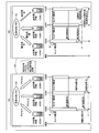
- FIG. 1 is an explanatory diagram illustrating an operation example of the thread processing system 100.
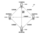
- FIG. 2 is an explanatory diagram illustrating a connection example in the thread processing system 100.
- FIG. 3 is a block diagram of hardware of the terminal device 103 # 0 according to the embodiment.
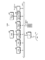
- FIG. 4 is a block diagram illustrating an example of functions of the thread processing system 100.
- FIG. 5 is an explanatory diagram showing an example of the contents stored in the synchronization waiting start time table 421.
- FIG. 6 is an explanatory diagram illustrating an example of generation of the access right priority information 423.
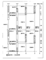
- FIG. 7 is an explanatory diagram showing an operation example of the thread processing system 100 when the access right priority information is set.
- FIG. 1 is an explanatory diagram illustrating an operation example of the thread processing system 100.
- FIG. 2 is an explanatory diagram illustrating a connection example in the thread processing system 100.
- FIG. 3 is a block diagram of hardware of the terminal device 103 # 0 according to the embodiment.
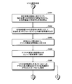
- FIG. 8 is a flowchart (part 1) illustrating an example of a processing procedure when a thread is executed by the master terminal device.
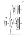
- FIG. 9 is a flowchart (part 2) illustrating an example of a processing procedure when a thread is executed by the master terminal device.
- FIG. 10 is a flowchart illustrating an example of a processing procedure when a slave terminal device executes a thread.
- FIG. 1 is an explanatory diagram showing an operation example of the thread processing system 100.
- the explanatory diagram denoted by reference numeral 101 shows an operation example of the thread processing system 100 in a state where the priority of the access right to the shared memory is not set.
- An explanatory diagram denoted by reference numeral 102 shows an operation example of the thread processing system 100 in a state in which the priority of the access right to the shared memory is set.
- the thread processing system 100 includes a plurality of terminal devices 103 such as mobile phones and mobile terminals.
- the thread processing system 100 shown in FIG. 1 includes terminal devices 103 # 0 to 103 # 2.
- the terminal devices 103 # 0 to 103 # 2 are connected by wireless communication such as a wireless LAN (Local Area Network) or Bluetooth (registered trademark).
- the terminal devices 103 # 0 to 103 # 2 can access the virtual shared memory 104.
- the terminal device 103 # 0 to the terminal device 103 # 2 execute a plurality of threads in synchronization by accessing the virtual shared memory 104.
- the storage location of the virtual shared memory 104 is a part of the storage area in the terminal device 103 # 0 to the terminal device 103 # 2.
- the master terminal device that controls the entire thread processing system 100 is the terminal device 103 # 0, and the slave terminal devices controlled by the master terminal device are the terminal device 103 # 1 and the terminal device 103 # 2. Also, the terminal device 103 # 2 has high processing performance, the terminal device 103 # 1 has low processing performance, and the terminal device 103 # 0 has intermediate processing performance between the terminal device 103 # 1 and the terminal device 103 # 2. Assume that you have.
- the terminal device 103 # 0 assigns thread 1 to the terminal device 103 # 1 and assigns thread 2 to the terminal device 103 # 2 after time t0.
- the terminal device 103 # 1 and the terminal device 103 # 2 execute the assigned thread.
- the terminal device 103 # 0 assigns the thread 0 to itself and executes it.
- the terminal devices 103 # 0 to 103 # 2 stand by until time t1 when all of the threads 0 to 2 are finished in order to synchronize the terminal devices.
- the high-performance terminal device 103 # 2 finishes the thread 2 early, notifies the execution result to the terminal device 103 # 0, and then enters a synchronization waiting state. After the notification by the terminal device 103 # 2, the terminal device 103 # 0 receives the execution result of the thread 2. Subsequently, the terminal device 103 # 0 having medium performance ends the thread 0. Finally, the low-performance terminal device 103 # 1 terminates the thread 1, and notifies the execution result to the terminal device 103 # 0. After the notification by the terminal device 103 # 1, the terminal device 103 # 0 receives the execution result of the thread 1.
- the terminal device 103 # 1 since the terminal device 103 # 1 becomes a bottleneck, the synchronization waiting time of the terminal device 103 # 2 becomes long, and the processing performance of the entire thread processing system 100 is degraded. State.
- the terminal apparatus 103 # 1 has a shorter synchronization waiting time, and the synchronization waiting time of the terminal apparatus 103 # 0 is intermediate between the terminal apparatus 103 # 1 and the terminal apparatus 103 # 2.
- the explanatory diagram denoted by reference numeral 102 shows a state in which the priority of the access right to the virtual shared memory 104 is set to the terminal devices 103 # 0 to 103 # 2.
- the thread processing system 100 sets the priority: high for the terminal device 103 # 1 for which the notification of the execution result is delayed in the thread processing system 100 denoted by reference numeral 101.
- the thread processing system 100 sets the terminal device 103 # 0 whose execution end time is medium to priority: medium, and sets the terminal device 103 # 0 whose notification of the execution result is early to low priority: low. Set.
- the terminal device 103 # 1 and the terminal device 103 # 3 access the virtual shared memory 104 at the same time, the terminal device 103 # 1 has priority and the virtual shared memory 104 is accessed.
- the terminal device 103 # 1 indicated by reference numeral 102 can terminate the thread 1 earlier than the terminal device 103 # 1 indicated by reference numeral 101. Since the thread 1 is terminated early, the synchronization waiting time is changed from t1 to t1 ′, and the synchronization waiting time of the terminal device 103 # 0 and the terminal device 103 # 2 is shortened. Therefore, the processing performance of the thread processing system 100 Will be improved.
- FIG. 2 is an explanatory diagram showing a connection example in the thread processing system 100.
- a thread processing system 100 shown in FIG. 2 includes a terminal device 103 # 3 in addition to the terminal devices 103 # 0 to 103 # 2 shown in FIG. It is assumed that the terminal device 103 # 3 has the same processing performance as the terminal device 103 # 2.
- the terminal devices 103 # 0 to 103 # 3 are connected by wireless communication.
- the terminal device 103 # 0 and the terminal device 103 # 2 are connected by high-speed communication such as a wireless LAN between the terminal device 103 # 0 and the terminal device 103 # 3, and between the terminal device 103 # 2 and the terminal device 103 # 3. .
- low-speed communication such as Bluetooth (registered trademark). Connected with.
- FIG. 3 is a block diagram of hardware of the terminal device 103 # 0 according to the embodiment.
- the terminal devices 103 # 1 to 103 # 3 have the same hardware as the terminal device 103 # 0 but have the same hardware. Also, since all the hardware appearing in the description of FIG. 3 is included in the terminal device 103 # 0, the suffix “# 0” is omitted for the sake of simplicity.
- the terminal device 103 # 0 includes a CPU 301, a ROM (Read-Only Memory) 302, and a RAM (Random Access Memory) 303.
- the terminal device 103 # 0 includes a flash ROM 304, a flash ROM controller 305, and a flash ROM 306.
- the terminal device 103 # 0 includes a display 307, an interface (I / F) 308, and a keyboard 309 as input / output devices for the user and other devices. Each unit is connected by a bus 310.
- the CPU 301 controls the entire terminal device 103 # 0.
- the CPU 301 may have a dedicated cache memory.
- the terminal device 103 may be a multi-core processor system including a plurality of cores.
- the multi-core processor system is a computer system including a processor having a plurality of cores. If a plurality of cores are mounted, a single processor having a plurality of cores may be used, or a processor group in which single core processors are arranged in parallel may be used.
- the ROM 302 stores a program such as a boot program.
- the RAM 303 is used as a work area for the CPU 301.
- the RAM 303 and the bus 310 are connected by a memory controller 311.
- the memory controller 311 controls access to the RAM 303 by the CPU 301. Further, the memory controller 311 may control access to the ROM 302, the flash ROM 304, etc. in addition to the RAM 303.
- the flash ROM 304 is a flash ROM having a high reading speed, for example, a NOR flash memory.
- the flash ROM 304 stores system software such as an OS (Operating System), application software, and the like.
- OS Operating System
- the terminal device 103 # 0 receives the new OS through the I / F 308, and updates the old OS stored in the flash ROM 304 to the received new OS.
- the flash ROM controller 305 controls reading / writing of data with respect to the flash ROM 306 according to the control of the CPU 301.
- the flash ROM 306 is a flash ROM mainly intended for data storage and transportation, and is, for example, a NAND flash memory.
- the flash ROM 306 stores data written under the control of the flash ROM controller 305. Specific examples of the data include image data and video data acquired by the user using the terminal device 103 # 0 through the I / F 308, and a program for executing the thread processing method according to the present embodiment.
- the flash ROM 306 for example, a memory card, an SD card, or the like can be adopted.
- the display 307 displays data such as a document, an image, and function information as well as a cursor, an icon, or a tool box.
- the display 307 can employ, for example, a TFT (Thin Film Transistor) liquid crystal display.
- TFT Thin Film Transistor
- the I / F 308 is connected to a network 312 such as a LAN, a WAN (Wide Area Network), and the Internet through a communication line, and is connected to another device via the network 312.
- the I / F 308 controls an internal interface with the network 312 and controls input / output of data from an external device.
- a modem or a LAN adapter may be employed as the I / F 308.
- the keyboard 309 has keys for inputting numbers, various instructions, etc., and inputs data.
- the keyboard 309 may be a touch panel type input pad or a numeric keypad.
- FIG. 4 is a block diagram illustrating an example of functions of the thread processing system 100.
- the thread processing system 100 includes a detection unit 401, an allocation unit 402, an execution unit 403, an acquisition unit 404, a registration unit 405, a calculation unit 406, a setting unit 407, a notification unit 408, and a control unit 409. And a management unit 410.
- the thread processing system 100 includes a management unit 411, a reception unit 412, an execution unit 413, and a control unit 414.
- the functions (detection unit 401 to control unit 414) serving as the control unit are realized by the CPU 301 # 0 and the CPU 301 # 1 executing the program stored in the storage device.
- the storage device is, for example, the ROM 302, the RAM 303, the flash ROM 304, the flash ROM 306, etc. shown in FIG.
- the thread processing system 100 can access the synchronization waiting start time table 421 and the shared memory 422. Furthermore, the thread processing system 100 generates access right priority information 423.
- the CPU 301 # 0 executes the OS 431 # 0 and the scheduler 432, and the CPU 301 # 1 executes the OS 431 # 1. Furthermore, the thread processing system 100 executes the application 433, the thread 0 in the application 433 is assigned to the CPU 301 # 0, and the thread 1 is assigned to the CPU 301 # 1.
- the detection unit 401 to the management unit 410 are functions of the terminal device 103 # 0 serving as a master terminal device, and the management unit 411 to the control unit 414 are functions of the terminal device 103 # 1 serving as a slave terminal device.
- terminal device 103 # 1 is a master terminal device
- terminal device 103 # 1 includes detection unit 401 to management unit 410.
- terminal device 103 # 0 is a slave terminal device
- terminal device 103 # 0 includes management unit 411 to control unit 414.
- the detection unit 401 to the execution unit 403 are included in the function of the scheduler 432.
- the acquisition unit 404 to the control unit 409 may be included in the function of the scheduler 432.
- the OS 431 is a program that controls the terminal device 103. Specifically, the OS 431 # 0 controls the terminal device 103 # 0, and the OS 431 # 1 controls the terminal device 103 # 1.
- the OS 431 provides a library used by the application 433, for example.
- the OS 431 includes device drivers that control the flash ROM controller 305, the I / F 308, the keyboard 309, and the like.
- the scheduler 432 is a program that determines the order in which threads in an application executed in the thread processing system 100 are allocated to the CPU 301. Further, the scheduler 432 according to the present embodiment is assumed to include a dispatch function for allocating a thread determined to be allocated next to the CPU 301. For example, the scheduler 432 assigns thread 0 to the CPU 301 # 0 and assigns thread 1 to the CPU 301 # 1.
- the synchronization waiting start time table 421 is a table that stores first time information when receiving the execution result of the corresponding thread from each of a plurality of devices. Specific storage contents of the synchronization waiting start time table 421 will be described later with reference to FIG.
- the synchronization waiting start time table 421 is stored in the RAM 303 # 0 of the terminal device 103 # 0 that is the master terminal device.
- the shared memory 422 is a real memory for the virtual shared memory 104.
- the shared memory 422 # 0, the shared memory 422 # 1, and the shared memory 422 in another terminal device 103 are combined to form the virtual shared memory 104.
- the shared memory 422 # 0 exists in the RAM 303 # 0, and the shared memory 422 # 1 exists in the RAM 303 # 1.
- the access right priority information 423 is information for storing the priority of the access right to the virtual shared memory 104 with a plurality of devices serving as slave terminal devices in a specific device serving as a master terminal device. A generation example of the access right priority information 423 will be described later with reference to FIG.
- the detection unit 401 has a function of detecting that a new thread allocation request has occurred. For example, the detection unit 401 detects that a new thread allocation request has occurred in the running application 433. As a specific detection method, when an API for executing a new thread is called in the execution code of the application 433 being executed, the detection unit 401 detects that a new thread allocation request has occurred.
- the detected allocation request is stored in a storage area such as a register, a cache memory, or a RAM 303 of the CPU 301 # 0.
- the allocation unit 402 has a function of allocating one thread among a plurality of threads to each of a plurality of devices serving as slave terminal devices in a specific device serving as a master terminal device.
- the assigning unit 402 may assign a thread to the master terminal device. For example, the assigning unit 402 assigns thread 0 to the CPU 301 # 0 and assigns thread 1 to the CPU 301 # 1.
- the assigning unit 402 notifies the device that performs the assignment of the assignment request.
- the information that the thread is allocated may be stored in a storage area such as a register of the CPU 301 # 0, a cache memory, or the RAM 303.
- the execution unit 403 and the execution unit 413 have a function of executing the assigned thread.
- the execution unit 403 executes thread 0 and the execution unit 413 executes thread 1.
- the execution result of the thread is stored in a storage area such as a register, a cache memory, or a RAM 303 of the CPU 301 # 0.
- the acquisition unit 404 has a function of acquiring first time information when receiving the execution result of the corresponding thread from each of the plurality of devices. For example, it is assumed that the time when the thread 0 starts execution is 0 [milliseconds] and the time when the thread 0 ends is 110 [milliseconds]. At this time, the acquisition unit 404 acquires the synchronization waiting start time as 110 [milliseconds], which is the first time information when the execution result of the thread 0 is received.
- the acquired synchronization wait start time is stored in a storage area such as the register of the CPU 301 # 0, the cache memory, and the RAM 303.
- the registration unit 405 has a function of registering first time information when a thread execution result is received from each of a plurality of devices. For example, the registration unit 405 registers 110 [milliseconds], which is the synchronization wait start time of the thread 0, in the synchronization wait start time table 421.
- the calculation unit 406 calculates the predetermined time of each of the plurality of devices based on the first time information and the second time information when the execution results of the plurality of threads have been received from the plurality of devices.
- the predetermined time is a synchronization waiting time from the time when the execution results from the target device are received to the time when the execution results from all threads are received.
- the calculated synchronization waiting time is stored in a storage area such as a register, a cache memory, or a RAM 303 of the CPU 301 # 0.
- the setting unit 407 has a function of setting the priority of the access right to the specific device and the shared memory 422 shared by the plurality of devices based on the first time information and the second time information of the plurality of devices. Since the priority of the access right to the shared memory 422 and the priority of the access right to the virtual shared memory 104 to which the shared memory 422 is combined are the same, the priority of the access right to the virtual shared memory 104 is hereinafter referred to. Make a uniform explanation at a degree.
- the first time information of the terminal device 103 # 0 is 110 [milliseconds]
- the first time information of the terminal device 103 # 1 is 190 [milliseconds]
- the second time information is 190 [milliseconds].
- the setting unit 407 sets the priority of the access right in descending order of the first time information.
- the setting unit 407 sets the priority of the terminal device 103 # 0 low and sets the priority of the terminal device 103 # 1 high.
- the setting unit 407 may set the priority of the access right based on the predetermined time calculated by the calculation unit 406. For example, it is assumed that the synchronization waiting time of the terminal device 103 # 0 is 80 [milliseconds] and the synchronization waiting time of the terminal device 103 # 1 is 0 [milliseconds] with respect to the synchronization waiting time that is a predetermined time. At this time, the setting unit 407 sets the priority of the access right in ascending order of the synchronization waiting time. Also in this example, the setting unit 407 sets the priority of the terminal device 103 # 0 low and sets the priority of the terminal device 103 # 1 high. The set priority is generated as access right priority information 423. The access right priority information 423 is stored in a storage area such as a register, a cache memory, or a RAM 303 of the CPU 301 # 0.
- the notification unit 408 has a function of notifying a plurality of devices of information regarding the priority of the access right. For example, the notification unit 408 notifies the terminal device 103 # 1 of the access right priority information 423 generated by the setting unit 407.
- the control unit 409 and the control unit 414 have a function of controlling the memory controller 311 that controls access to the shared memory 422 according to the priority of the access right. For example, it is assumed that the setting unit 407 sets the priority of the terminal device 103 # 0 low and sets the priority of the terminal device 103 # 1 high.
- the control unit 409 temporarily stops the access from the CPU 301 # 0.
- the memory controller 311 # 0 is controlled.
- the control unit 409 accesses the shared memory 422 # 0 via the I / F 308 # 0.
- the control unit 409 controls the operation of the memory controller 311 # 0 by writing the priority of each terminal device 103 into the setting register of the memory controller 311 # 0.
- the control unit 414 controls the memory controller 311 # 1 according to the priority of the access right received by the receiving unit 412.
- the management unit 410 and the management unit 411 have a function of managing the virtual shared memory 104.
- the management unit 410 converts access from the thread 0 to the virtual shared memory 104 into access to the shared memory 422 # 0 and the shared memory 422 # 1 that are real memories corresponding to the virtual shared memory 104.
- the management unit 410 notifies the access request to the terminal device 103 # 1 via the I / F 308 # 0.
- the reception unit 412 has a function of receiving the priority of the access right. For example, the reception unit 412 receives the access right priority information 423 from the terminal device 103 # 0. Furthermore, the reception unit 412 receives a thread allocation request. The received access right priority information 423 and thread allocation request information are stored in a storage area such as a register, a cache memory, and a RAM 303 of the CPU 301 # 1.
- FIG. 5 is an explanatory diagram showing an example of the contents stored in the synchronization waiting start time table 421.
- the synchronization wait start time table 421 includes two fields: a terminal device ID (IDentification) and a synchronization wait start time.
- IDentification identification information of the terminal devices 103 # 0 to 103 # 3 is stored.
- the synchronization wait start time field stores the time at which the terminal devices 103 # 0 to 103 # 3 start waiting for synchronization.
- the synchronization waiting start time table 421 shown in FIG. 5 includes records 421-0 to 421-3.
- the time when the execution of the thread accompanied by the synchronization process is started is 0 [millisecond].
- the synchronization waiting start time of the terminal device 103 # 0 is 110 [milliseconds]
- the synchronization waiting start time of the terminal device 103 # 1 is 190 [milliseconds]. It shows that there is.
- the synchronization waiting start time of the terminal apparatus 103 # 2 is 70 [milliseconds]
- the synchronization waiting start time of the terminal apparatus 103 # 3 is 60 [milliseconds]. It is shown that.
- FIG. 6 is an explanatory diagram showing an example of generation of the access right priority information 423.
- the master terminal device that generates the access right priority information 423 receives the execution results from all of the terminal devices 103 that execute the thread that performs the synchronization processing, the master terminal device calculates the synchronization waiting time.
- the master terminal device may also execute a thread for performing the synchronization process.
- the timing for starting the calculation of the synchronization waiting time is when the master terminal device ends the thread, and the slave terminal device also ends the thread.
- the master terminal device calculates the synchronization waiting time by the following equation (1).
- Synchronization wait time Terminal device synchronization wait start time that received the execution result last-Terminal device synchronization wait start time (1)
- the master terminal device identifies the terminal device 103 # 1 as the terminal device that has received the execution result last from the synchronization wait start time field of the records 421-0 to 421-3. Subsequently, the master terminal device calculates the synchronization waiting time of the terminal device 103 # 0 from the equation (1) as follows.
- the master terminal device also calculates the synchronization waiting time of the terminal devices 103 # 1 to 103 # 3 as 0 [milliseconds], 120 [milliseconds], and 130 [milliseconds], respectively. After the calculation, the master terminal device sets the priority of the access right to the virtual shared memory 104 in ascending order of the synchronization waiting time. The priority of the set access right is generated as access right priority information 423.
- the access right priority information 423 includes two fields: a terminal device ID and a priority.
- the terminal device ID field identification information of the terminal devices 103 # 0 to 103 # 3 is stored.
- the priority field the priority of the access right to the virtual shared memory 104 is stored. Note that the priority shown in FIG. 6 is defined as a state where 1 is the highest priority and the priority is lower as the numerical value is larger.
- the master terminal device sets the terminal device 103 # 1 having the shortest synchronization waiting time to the priority level 1. Subsequently, the master terminal device sets the terminal device 103 # 0 to priority 2, the terminal device 103 # 2 to priority 3, and sets the terminal device 103 # 3 to priority 4 in ascending order of synchronization waiting time. Set to.
- FIG. 7 is an explanatory diagram showing an operation example of the thread processing system 100 when the access right priority information is set.
- the thread processing system 100 illustrated in FIG. 7 executes the threads 0 to 3 from 0 [milliseconds], and executes the threads 0 'to 3' at 200 [milliseconds].
- the processing amounts of the threads 0 to 3 and the threads 0 'to 3' are the same.
- the thread processing system 100 of 0 [milliseconds] to 190 [milliseconds] is in a state where the priority of the access right to the virtual shared memory 104 is not set. Subsequently, the thread processing system 100 for 190 [milliseconds] to 200 [milliseconds] executes processing for setting the priority of the access right to the virtual shared memory 104. Furthermore, the thread processing system 100 of 200 [milliseconds] to 370 [milliseconds] is in a state in which the priority of the access right to the virtual shared memory 104 is set.
- terminal device 103 # 0 which is a master terminal device, communicates with terminal devices 103 # 1 to 103 # 3, which are slave terminal devices, and does not communicate between terminal devices 103 # 1 to 103 # 3. Is assumed. Therefore, the terminal device 103 # 0 performs high-speed communication with the terminal device 103 # 2 and the terminal device 103 # 3, and performs low-speed communication with the terminal device 103 # 1.
- the processing time of thread 0 of terminal device 103 # 0 is 60 [milliseconds]
- the processing time of thread 1 of terminal device 103 # 1 is 110 [milliseconds]
- the processing of thread 2 of terminal device 103 # 2 The processing time of the thread 3 of the terminal device 103 # 3 is 40 [milliseconds].
- the communication time between the terminal device 103 # 0 and the terminal device 103 # 1 which is low-speed communication is 30 [milliseconds]. It is assumed that the communication time between the terminal device 103 # 0 and the terminal device 103 # 2 and the terminal device 103 # 0 and the terminal device 103 # 3, which are high-speed communications, is 10 [milliseconds].
- the terminal device 103 # 0 assigns thread 0 to thread 3 to the terminal device 103 # 0 to terminal device 103 # 3 at time 0 [milliseconds].
- the terminal devices 103 # 0 to 103 # 3 to which the thread is assigned access the virtual shared memory 104 in order to execute the thread. It is assumed that the shared memory 422 corresponding to the virtual shared memory 104 accessed at this time is the shared memory 422 # 0. Therefore, the terminal devices 103 # 1 to 103 # 3 communicate with the terminal device 103 # 0.
- terminal device 103 # 3 which is high-speed communication and has been able to start communication earliest, communicates with terminal device 103 # 0.
- the terminal device 103 # 0 and the terminal device 103 # 3 start communication next.
- the terminal device 103 # 3 that has finished the communication executes the thread 3.
- the terminal device 103 # 0 and the terminal device 103 # 2 ends at time 20 [milliseconds]
- the terminal device 103 # 0 and the terminal device 103 # 1 start communication.
- the terminal device 103 # 3 that has finished the communication executes the thread 2.
- the terminal device 103 # 3 terminates the thread 3 at the time of 50 [milliseconds] after 40 [milliseconds] from the time of 10 [milliseconds], and the execution result at the time 60 [milliseconds].
- the terminal device 103 # 0 receives the execution result, and registers the synchronization waiting start time of the terminal device 103 # 3 as 60 [milliseconds] in the synchronization waiting start time table 421.
- the terminal device 103 # 2 ends the thread 2, and notifies the terminal device 103 # 0 of the execution result.
- the terminal device 103 # 0 accepts the execution result and registers it in the synchronization waiting start time table 421 with the synchronization waiting start time of the terminal device 103 # 2 set to 70 [milliseconds].
- the terminal device 103 # 0 When the terminal device 103 # 0 ends the thread 0 at time 110 [milliseconds], the terminal device 103 # 0 sets the synchronization waiting start time of the terminal device 103 # 0 to 110 [milliseconds] and waits for synchronization. Register in the start time table 421. Further, at time 160 [milliseconds], the terminal device 103 # 1 ends the thread 1, and at time 190 [milliseconds], notifies the terminal device 103 # 0 of the execution result. The terminal device 103 # 0 registers the synchronization waiting start time of the terminal device 103 # 1 as 190 [milliseconds] in the synchronization waiting start time table 421. Since all the terminal devices 103 have finished the thread, the master terminal device starts executing the next process.
- the terminal device 103 # 0 calculates the synchronization waiting time of each terminal device 103.
- the synchronization waiting times of the terminal devices 103 # 0 to 103 # 3 are calculated as 80 [milliseconds], 0 [milliseconds], 120 [milliseconds], and 130 [milliseconds], respectively. From the calculation result, the terminal device 103 # 0 assigns the access right to the virtual shared memory 104 of the terminal device 103 # 0 to the terminal device 103 # 3 with priority: 2, priority: 1, priority: 3, Priority: Set to 4.
- the terminal device 103 # 0 assigns the thread 0 'to the thread 3' to the terminal devices 103 # 1 to 103 # 3 at 200 [milliseconds].
- the terminal devices 103 # 1 to 103 # 3 to which the thread is assigned access the virtual shared memory 104 in order to execute the thread.
- Terminal apparatuses 103 # 1 to 103 # 3 communicate with terminal apparatus 103 # 0.
- the terminal device 103 # 3 which is high-speed communication and was able to start communication earliest, communicates with the terminal device 103 # 0.
- the terminal device 103 # 0 temporarily stops access to the shared memory 422 # 0 by the terminal device 103 # 3, and the terminal device 103 The shared memory 422 # 0 is accessed from # 1.
- the terminal device 103 # 2 with the next highest priority starts communication with the terminal device 103 # 0.
- the terminal device 103 # 3 with the next highest priority starts communication with the terminal device 103 # 0.
- the terminal device 103 # 3 with the next highest priority starts communication with the terminal device 103 # 0.
- the assigned thread 0 'to thread 3' are executed in order from the terminal device 103 that has completed communication.
- the terminal device 103 # 2 notifies the execution result of the thread 2 'at time 290 [milliseconds], and the terminal device 103 # 0 receives the execution result of the thread 2'.
- the terminal device 103 # 3 notifies the execution result of the thread 3 'at time 300 [milliseconds], and the terminal device 103 # 0 receives the execution result of the thread 3'.
- the terminal device 103 # 1 notifies the execution result of the thread 1 'at time 370 [milliseconds], and the terminal device 103 # 0 receives the execution result of the thread 1'.
- the priority of the access right to the virtual shared memory 104 is set, so that the thread processing system 100 can quickly end the processing of the terminal device 103 # 1 that has become a bottleneck, and the thread processing system 100 Can improve the processing performance.
- the thread processing system 100 in which the priority of the access right to the virtual shared memory 104 is not set 190 [milliseconds] have elapsed until all threads are terminated.
- the thread processing system 100 in which the priority of the access right to the virtual shared memory 104 is set it takes 170 [milliseconds] until all threads are completed, and the processing performance can be improved.
- FIGS. 8 to 10 are flowcharts showing an example of a processing procedure at the time of executing a thread for performing the operation shown in FIG. 8 and 9 show a processing procedure at the time of thread execution by the master terminal device, and FIG. 10 shows a processing procedure at the time of thread execution by the slave terminal device that operates by notification from the master terminal device.
- FIG. 8 is a flowchart (part 1) illustrating an example of a processing procedure during thread execution by the master terminal device.
- the master terminal apparatus determines whether a new thread allocation request has occurred (step S801). If a new thread allocation request has not occurred (step S801: No), the master terminal apparatus executes the process of step S801 again after a predetermined time has elapsed.
- step S801 When a new thread allocation request is generated (step S801: Yes), the master terminal apparatus notifies the master terminal apparatus or slave terminal apparatus of a new thread allocation request (step S802). If a plurality of new threads are generated, the master terminal device executes a plurality of processes in step S802. Further, the process of determining which terminal device to assign a new thread to among the master terminal device and the slave terminal device is included in the function of the scheduler. For example, the scheduler may assign a new thread to the terminal device having the smallest load among the master terminal device and the slave terminal device. After the thread assignment, the master terminal device executes the thread assigned to the master terminal device (step S803).
- the master terminal device determines whether or not the processing of the assigned thread has been completed (step S804).
- the master terminal device acquires the time when the execution result of the master terminal device is received as the synchronization waiting start time (step S805).
- the master terminal device registers the acquired synchronization wait start time in the synchronization wait start time table 421 (step S806).
- the master terminal device determines whether or not an execution result has been received from the slave terminal device (step S807). Note that the execution result of the slave terminal apparatus is notified by the process of step S1004 described later.
- step S807: Yes the master terminal device acquires the time when the execution result is received from the slave terminal device as the synchronization waiting start time (step S808). After the acquisition, the master terminal device registers the acquired synchronization wait start time in the synchronization wait start time table 421 (step S809). After storage or when the execution result is not received (step S807: No), the master terminal device determines whether or not all the execution results of the assigned thread have been received (step S810). When not receiving all the execution results (step S810: No), the master terminal device proceeds to the process of step S804. When all the execution results are received (step S810: Yes), the master terminal device proceeds to the process of step S901.
- FIG. 9 is a flowchart (part 2) illustrating an example of a processing procedure when a thread is executed by the master terminal device.
- the master terminal device calculates the synchronization waiting time of each terminal device 103 from the synchronization waiting start time of the terminal device 103 that lastly received the execution result (step S901). After the calculation, the master terminal device sets the priority of the access right to the virtual shared memory 104 according to the synchronization waiting time of each terminal device 103 (step S902).
- the master terminal device generates access right priority information 423 from the set priority (step S903), and notifies the access right priority information 423 to the slave terminal device (step S904).
- the master terminal device sets the priority of the access right to the shared memory 422 of the master terminal device in the memory controller 311 of the master terminal device (step S905), and proceeds to the processing of step S801.
- FIG. 10 is a flowchart showing an example of a processing procedure during thread execution by the slave terminal device.
- the slave terminal device confirms whether or not the notification from the master terminal has been received (step S1001). Note that the notification from the master terminal device is notified by the processing of step S802 and step S905. When the notification is not received from the master terminal device (step S1001: no notification), the slave terminal device proceeds to the process of step S1001 after a predetermined time has elapsed.
- step S1001 access right priority information 423
- the slave terminal device sets the priority of the access right to the shared memory 422 of the slave terminal device.
- the memory controller 311 of the slave terminal device is set (step S1002). After the setting, the slave terminal device proceeds to the process of step S1001.
- step S1002 thread allocation request
- step S1003 the slave terminal device executes the thread for which the allocation request has been made. After the execution is completed, the slave terminal device notifies the execution result of the thread to the master terminal device, and the process proceeds to step S1001.
- the thread processing method and the thread processing system when synchronization processing is performed by a plurality of terminal devices, priority is given to the access right to the shared memory of the low-performance terminal device that causes other terminal devices to wait for a long time. Set the degree higher. As a result, the execution time of the low-performance terminal device is shortened and the synchronization waiting time of other terminal devices is reduced, so that the thread processing system can improve the overall processing performance.
- the method of redundantly arranging data has a problem that the used memory capacity increases. Since a terminal device such as a mobile phone to which the present embodiment is applied has a limited memory capacity, it is difficult to apply a redundant arrangement of data having a large memory usage capacity. Since the thread processing system according to the present embodiment does not require redundant arrangement of data, the memory capacity can be reduced and can be applied to a terminal device.
- the thread processing system may notify the priority level of the access right to the shared memory from the master terminal device to the slave terminal device. Thereby, it is possible to operate a virtual distributed shared memory in which priority control is performed in all terminal devices.
- the thread processing system calculates the synchronization waiting time of each terminal device from the first time information when receiving the execution results of the plurality of threads and the second time information when receiving the execution results of the plurality of threads.
- the priority may be set based on the synchronization waiting time.
- a terminal device that becomes a bottleneck has low processing performance or low-speed communication.
- the thread processing system according to the present embodiment can detect a terminal device that becomes a bottleneck according to the time when the execution result is received without acquiring the processing performance of the terminal and the communication speed. Therefore, the thread processing system according to the present embodiment does not need to communicate new information other than the priority information of the shared memory between terminals.
- the thread processing system may set the priority of the access right to the shared memory high when the synchronization waiting time is small. Thereby, the thread processing system becomes a bottleneck, the priority of the terminal device whose synchronization waiting time is reduced can be set high, and the overall processing performance can be improved.
- the thread processing method described in the present embodiment can be realized by executing a program prepared in advance on a computer such as a personal computer or a workstation.
- a thread processing program for executing this thread processing method is recorded on a computer-readable recording medium such as a hard disk, a flexible disk, a CD-ROM, an MO, and a DVD, and is executed by being read from the recording medium by the computer.
- the thread processing program may be distributed via a network such as the Internet.
Landscapes
- Engineering & Computer Science (AREA)
- Software Systems (AREA)
- Theoretical Computer Science (AREA)
- Physics & Mathematics (AREA)
- General Engineering & Computer Science (AREA)
- General Physics & Mathematics (AREA)
- Multi Processors (AREA)
Abstract
同期処理に伴うシステム全体の処理性能を向上させる。スレッド処理システム(100)は、端末装置(103#0)~端末装置(103#2)にスレッド(0)~スレッド(2)を割り当てる。割り当てた結果、高処理性能である端末装置(103#2)は、スレッド(2)を早く終了し、実行結果を端末装置(103#0)に通知した後、同期待ち状態となる。低処理性能である端末装置(103#1)は、スレッド(1)を遅く終了する。端末装置(103#0)は、各端末装置からの実行結果を受け付けた時刻に基づいて、仮想共有メモリ(104)への優先度を設定する。これにより優先度:高が設定された端末装置(103#1)は、スレッド(1)の実行時間が短くなり、スレッド(2)を実行している端末装置(103#2)の同期待ち時間を短縮するため、スレッド処理システム(100)の全体の処理性能が向上する。
Description
本発明は、分散処理を行うスレッド処理方法、およびスレッド処理システムに関する。
従来から、複数の端末装置でデータを共有する技術として、各端末装置の実メモリに分散された分割されたデータを保持する仮想分散共有メモリという技術が開示されている。仮想分散共有メモリは、たとえば、インターネットなどの広域のネットワーク上にある装置を、一つの複合したコンピュータシステムとして提供するグリッド・コンピューティングにて使用されている。
仮想分散共有メモリの特徴として、アクセスの分散が図られ、ネットワークの負荷を軽減させることができる。また、端末装置で実行されるアプリケーションソフトウェア(以下、アプリ)が仮想分散共有メモリを意識することなく、一つの連続したメモリとしてアクセスすることが可能である。また、複数の端末装置で実行されるアプリは、各端末装置にスレッドを割り当てて分散処理、並列処理を実行する。なお、スレッドとは、プログラムの実行単位である。
仮想分散共有メモリに関する技術として、たとえば、有線による広域ネットワークで接続された装置のメモリを、仮想分散共有メモリとして使用する技術が開示されている。または、無線ネットワークの例にて、送受信バッファを仮想化することで、データをリレーし、直接接続されていない端末装置でデータを送受信できる技術が開示されている(たとえば、下記特許文献1、2を参照。)。
また、仮想分散共有メモリを用いた情報ストレージシステムにおいて、利用者が生産する情報を意味付けした情報要素として蓄積する。続けて、複数の端末装置からの情報取得要求があった場合、動的に情報取得要求を処理するマスタ端末装置を決定して、情報取得要求に対する情報を効率的に交換、または複製する技術が開示されている(たとえば、下記特許文献3を参照。)。
上述した従来技術において、複数の分散処理、並列処理を実行する場合、複数の端末装置で同期処理を行いながら処理を実行することがある。同期処理とは、複数のスレッドの処理を特定のコード位置までで一旦停止させ、全てのスレッドが特定のコード位置に到達した際に、次の処理を継続する処理である。停止中となったスレッドを実行している端末装置は、同期待ちの状態となる。このとき、各スレッドが割り当てられた端末装置の処理性能や通信速度が異なる場合、処理性能、通信速度が高い端末装置での同期待ちの時間が長くなり、システム全体の処理性能が低下するという問題があった。
本発明は、上述した従来技術による問題点を解消するため、同期処理に伴うシステム全体の処理性能の低下を抑止するスレッド処理方法、およびスレッド処理システムを提供することを目的とする。
上述した課題を解決し、目的を達成するため、本発明の一側面によれば、特定の装置は複数の装置のそれぞれに複数のスレッドのうちの一のスレッドを割り当て、複数の装置のそれぞれから対応するスレッドの実行結果を受け付けるときの第1時刻情報を取得し、複数の装置から複数のスレッドの実行結果を受け付け終わったときの第2時刻情報と第1時刻情報とに基づいて、複数の装置の特定の装置および複数の装置で共有される共有メモリへのアクセス権の優先度を設定するスレッド処理方法、およびスレッド処理システムが提案される。
本発明の一側面によれば、同期処理に伴うシステム全体の処理性能の低下を抑止できるという効果を奏する。
以下に添付図面を参照して、開示のスレッド処理方法、およびスレッド処理システムの実施の形態を詳細に説明する。
図1は、スレッド処理システム100の動作例を示す説明図である。符号101で示す説明図は、共有メモリへのアクセス権の優先度が設定されていない状態でのスレッド処理システム100の動作例を示している。また、符号102で示す説明図は、共有メモリへのアクセス権の優先度が設定されている状態でのスレッド処理システム100の動作例を示している。
スレッド処理システム100は、携帯電話や携帯端末等といった端末装置103を複数含む。たとえば、図1で示すスレッド処理システム100は、端末装置103#0~端末装置103#2を含む。以下、接尾記号“#n”が付随された記号は、n番目の端末装置103に対応する記号であることを示している。端末装置103#0~端末装置103#2は、無線LAN(Local Area Network)、Bluetooth(登録商標)等の無線通信によって接続されている。また、端末装置103#0~端末装置103#2は、仮想共有メモリ104にアクセス可能である。端末装置103#0~端末装置103#2は、仮想共有メモリ104にアクセスすることで複数のスレッドを同期しつつ実行する。なお、仮想共有メモリ104の格納箇所は、端末装置103#0~端末装置103#2内の記憶領域の一部となる。
また、スレッド処理システム100全体を制御するマスタ端末装置が端末装置103#0となり、マスタ端末装置によって制御されるスレーブ端末装置が端末装置103#1、端末装置103#2であることを想定する。また、端末装置103#2は高処理性能であり、端末装置103#1は低処理性能であり、端末装置103#0は、端末装置103#1と端末装置103#2の中間の処理性能を有していることを想定する。
このような状態で、符号101で示す説明図では、端末装置103#0が、時刻t0以降にて、端末装置103#1にスレッド1を割り当て、端末装置103#2にスレッド2を割り当てる。端末装置103#1、端末装置103#2は、割り当てられたスレッドを実行する。また、端末装置103#0は、自身にもスレッド0を割り当てて実行する。端末装置103#0~端末装置103#2は、端末装置間で同期を取るために、スレッド0~スレッド2が全て終了する時刻t1まで待機する。
高性能である端末装置103#2はスレッド2を早く終了し、実行結果を端末装置103#0に通知した後、同期待ち状態となる。端末装置103#2による通知後、端末装置103#0は、スレッド2の実行結果を受け付ける。続けて、中性能である端末装置103#0がスレッド0を終了する。最後に、低性能である端末装置103#1がスレッド1を終了し、実行結果を端末装置103#0に通知する。端末装置103#1による通知後、端末装置103#0は、スレッド1の実行結果を受け付ける。
結果、符号101で示すスレッド処理システム100は、端末装置103#1がボトルネックとなったため、端末装置103#2の同期待ち時間が長くなり、スレッド処理システム100全体の処理性能が低下している状態である。また、端末装置103#1は、同期待ち時間が短くなり、端末装置103#0の同期待ち時間は、端末装置103#1と端末装置103#2の中間となる。
次に、符号102で示す説明図は、仮想共有メモリ104へのアクセス権の優先度を端末装置103#0~端末装置103#2に設定した状態である。具体的には、符号101で示すスレッド処理システム100にて実行結果の通知が遅かった端末装置103#1を、スレッド処理システム100は、優先度:高に設定する。また、スレッド処理システム100は、実行終了の時刻が中程度となった端末装置103#0を優先度:中に設定し、実行結果の通知が早かった端末装置103#0を優先度:低に設定する。
このようなアクセス権の優先度を設定することで、たとえば、端末装置103#1と端末装置103#3が同時に仮想共有メモリ104にアクセスした場合、端末装置103#1が優先して仮想共有メモリ104にアクセスするようになる。これにより、符号102で示す端末装置103#1は、符号101で示す端末装置103#1より、スレッド1を早く終了することができる。スレッド1が早く終了することで、同期待ちが終了する時刻がt1からt1’となり、端末装置103#0、端末装置103#2の同期待ち時間が短縮されるため、スレッド処理システム100の処理性能が向上することになる。
図2は、スレッド処理システム100内の接続例を示す説明図である。図2で示すスレッド処理システム100は、図1で示した端末装置103#0~端末装置103#2に加えて、端末装置103#3を含む。端末装置103#3は、端末装置103#2と同等の処理性能となることを想定する。
また、端末装置103#0~端末装置103#3は、無線通信で接続されている。端末装置103#0と端末装置103#2間、端末装置103#0と端末装置103#3間、端末装置103#2と端末装置103#3間は、無線LANといった高速通信で接続されている。また、端末装置103#0と端末装置103#1間、端末装置103#1と端末装置103#2間、端末装置103#1と端末装置103#3間は、Bluetooth(登録商標)といった低速通信で接続されている。
図3は、実施の形態にかかる端末装置103#0のハードウェアを示すブロック図である。なお、端末装置103#1~端末装置103#3は、端末装置103#0と処理性能が異なるが同一のハードウェアを含むため、説明を省略する。また、図3の説明に登場するハードウェアは、全て端末装置103#0に含まれているため、説明の簡略化のため接尾記号“#0”を省略する。
図3において、端末装置103#0は、CPU301と、ROM(Read‐Only Memory)302と、RAM(Random Access Memory)303と、を含む。また、端末装置103#0は、フラッシュROM304と、フラッシュROMコントローラ305と、フラッシュROM306と、を含む。また、端末装置103#0は、ユーザやその他の機器との入出力装置として、ディスプレイ307と、I/F(Interface)308と、キーボード309と、を含む。また、各部はバス310によってそれぞれ接続されている。
ここで、CPU301は、端末装置103#0の全体の制御を司る。また、CPU301は、専用のキャッシュメモリを有してもよい。また、端末装置103は、複数のコアを含むマルチコアプロセッサシステムであってもよい。なお、マルチコアプロセッサシステムとは、コアが複数搭載されたプロセッサを含むコンピュータのシステムである。コアが複数搭載されていれば、複数のコアが搭載された単一のプロセッサでもよく、シングルコアのプロセッサが並列されているプロセッサ群でもよい。
ROM302は、ブートプログラムなどのプログラムを記憶している。RAM303は、CPU301のワークエリアとして使用される。また、RAM303とバス310は、メモリコントローラ311で接続されている。メモリコントローラ311は、CPU301によるRAM303へのアクセスの制御をする。また、メモリコントローラ311は、RAM303以外にも、ROM302、フラッシュROM304などのアクセスを制御してもよい。
フラッシュROM304は、読出し速度が高速なフラッシュROMであり、たとえば、NOR型フラッシュメモリである。たとえば、フラッシュROM304は、OS(Operating System)などのシステムソフトウェアやアプリケーションソフトウェアなどを記憶している。たとえば、OSを更新する場合、端末装置103#0は、I/F308によって新しいOSを受信し、フラッシュROM304に格納されている古いOSを、受信した新しいOSに更新する。
フラッシュROMコントローラ305は、CPU301の制御に従ってフラッシュROM306に対するデータのリード/ライトを制御する。フラッシュROM306は、データの保存、運搬を主に目的としたフラッシュROMであり、たとえば、NAND型フラッシュメモリである。フラッシュROM306は、フラッシュROMコントローラ305の制御で書き込まれたデータを記憶する。データの具体例としては、端末装置103#0を使用するユーザがI/F308を通して取得した画像データ、映像データや、また本実施の形態にかかるスレッド処理方法を実行するプログラムなどである。フラッシュROM306は、たとえば、メモリカード、SDカードなどを採用することができる。
ディスプレイ307は、カーソル、アイコンあるいはツールボックスをはじめ、文書、画像、機能情報などのデータを表示する。ディスプレイ307は、たとえば、TFT(Thin Film Transistor)液晶ディスプレイなどを採用することができる。
I/F308は、通信回線を通じてLAN、WAN(Wide Area Network)、インターネットなどのネットワーク312に接続され、ネットワーク312を介して他の装置に接続される。そして、I/F308は、ネットワーク312と内部のインターフェースを司り、外部装置からのデータの入出力を制御する。I/F308には、たとえばモデムやLANアダプタなどを採用することができる。
キーボード309は、数字、各種指示などの入力のためのキーを有し、データの入力を行う。また、キーボード309は、タッチパネル式の入力パッドやテンキーなどであってもよい。
(スレッド処理システム100の機能)
次に、スレッド処理システム100の機能例について説明する。図4は、スレッド処理システム100の機能例を示すブロック図である。スレッド処理システム100は、検出部401と、割当部402と、実行部403と、取得部404と、登録部405と、算出部406と、設定部407と、通知部408と、制御部409と、管理部410と、を含む。さらに、スレッド処理システム100は、管理部411と、受付部412と、実行部413と、制御部414と、を含む。
次に、スレッド処理システム100の機能例について説明する。図4は、スレッド処理システム100の機能例を示すブロック図である。スレッド処理システム100は、検出部401と、割当部402と、実行部403と、取得部404と、登録部405と、算出部406と、設定部407と、通知部408と、制御部409と、管理部410と、を含む。さらに、スレッド処理システム100は、管理部411と、受付部412と、実行部413と、制御部414と、を含む。
この制御部となる機能(検出部401~制御部414)は、記憶装置に記憶されたプログラムをCPU301#0、CPU301#1が実行することにより、その機能を実現する。記憶装置とは、具体的には、たとえば、図3に示したROM302、RAM303、フラッシュROM304、フラッシュROM306などである。
また、スレッド処理システム100は、同期待ち開始時刻テーブル421、共有メモリ422にアクセス可能である。さらに、スレッド処理システム100は、アクセス権優先度情報423を生成する。また、CPU301#0は、OS431#0、スケジューラ432を実行し、CPU301#1は、OS431#1を実行する。さらに、スレッド処理システム100は、アプリ433を実行しており、アプリ433内のスレッド0がCPU301#0に割り当てられており、スレッド1がCPU301#1に割り当てられている。
また、検出部401~管理部410は、マスタ端末装置となる端末装置103#0の機能であり、管理部411~制御部414は、スレーブ端末装置となる端末装置103#1の機能である。なお、端末装置103#1がマスタ端末装置となる場合、端末装置103#1は検出部401~管理部410を含む。また、端末装置103#0がスレーブ端末装置となる場合、端末装置103#0は管理部411~制御部414を含む。また、検出部401~実行部403は、スケジューラ432の機能に含まれる。なお、取得部404~制御部409がスケジューラ432の機能に含まれてもよい。
OS431は、端末装置103を制御するプログラムである。具体的に、OS431#0は端末装置103#0を制御しており、OS431#1は端末装置103#1を制御している。OS431は、たとえば、アプリ433が使用するライブラリを提供する。また、OS431は、フラッシュROMコントローラ305、I/F308、キーボード309等を制御するデバイスドライバを有している。
スケジューラ432は、スレッド処理システム100で実行されているアプリ内のスレッドをCPU301に割り当てる順番を決定するプログラムである。また、本実施の形態にかかるスケジューラ432は、次に割り当てられることが決定したスレッドをCPU301に割り当てるディスパッチ機能が含まれていることを想定している。たとえば、スケジューラ432は、スレッド0をCPU301#0に割り当て、スレッド1をCPU301#1に割り当てる。
同期待ち開始時刻テーブル421は、複数の装置のそれぞれから対応するスレッドの実行結果を受け付けるときの第1時刻情報を記憶するテーブルである。同期待ち開始時刻テーブル421の具体的な記憶内容については、図5にて後述する。なお、同期待ち開始時刻テーブル421は、マスタ端末装置である端末装置103#0のRAM303#0内に記憶される。
共有メモリ422は、仮想共有メモリ104に対する実メモリである。共有メモリ422#0、共有メモリ422#1、また、他の端末装置103内にある共有メモリ422が結合され仮想共有メモリ104を形成する。なお、共有メモリ422#0はRAM303#0内に存在し、共有メモリ422#1はRAM303#1内に存在する。
アクセス権優先度情報423は、マスタ端末装置となる特定の装置にて、スレーブ端末装置となる複数の装置との仮想共有メモリ104へのアクセス権の優先度を記憶する情報である。アクセス権優先度情報423の生成例については、図6にて後述する。
検出部401は、新たなスレッドの割当要求が発生したことを検出する機能を有する。たとえば、検出部401は、実行中のアプリ433にて、新たなスレッドの割当要求が発生したことを検出する。具体的な検出方法として、実行中のアプリ433の実行コードに、新規スレッドを実行するAPIが呼び出された場合、検出部401は、新たなスレッドの割当要求が発生したことを検出する。なお、検出された割当要求は、CPU301#0のレジスタ、キャッシュメモリ、RAM303などの記憶領域に記憶される。
割当部402は、マスタ端末装置となる特定の装置にてスレーブ端末装置となる複数の装置のそれぞれに複数のスレッドのうちの一のスレッドを割り当てる機能を有する。また、割当部402は、マスタ端末装置にスレッドを割り当ててもよい。たとえば、割当部402は、スレッド0をCPU301#0に割り当て、スレッド1をCPU301#1に割り当てる。割当部402は、自装置以外にスレッドを割り当てる場合、割当を行う装置に対して、割当要求を通知する。なお、スレッドを割り当てるという情報は、CPU301#0のレジスタ、キャッシュメモリ、RAM303などの記憶領域に記憶されてもよい。
実行部403、実行部413は、割り当てられたスレッドを実行する機能を有する。たとえば、実行部403はスレッド0を実行し、実行部413はスレッド1を実行する。なお、スレッドの実行結果は、CPU301#0のレジスタ、キャッシュメモリ、RAM303などの記憶領域に記憶される。
取得部404は、複数の装置のそれぞれから対応するスレッドの実行結果を受け付けるときの第1時刻情報を取得する機能を有する。たとえば、スレッド0が実行開始した時刻を0[ミリ秒]とし、スレッド0が終了した時刻を110[ミリ秒]とする場合を想定する。このとき、取得部404は、スレッド0の実行結果を受け付けるときの第1時刻情報となる同期待ち開始時刻を110[ミリ秒]として取得する。なお、取得された同期待ち開始時刻は、CPU301#0のレジスタ、キャッシュメモリ、RAM303などの記憶領域に記憶される。
登録部405は、複数の装置のそれぞれからスレッドの実行結果を受け付けるときの第1時刻情報を登録する機能を有する。たとえば、登録部405は、スレッド0の同期待ち開始時刻となった110[ミリ秒]を同期待ち開始時刻テーブル421に登録する。
算出部406は、第1時刻情報と複数の装置から複数のスレッドの実行結果を受け付け終わったときの第2時刻情報とに基づいて複数の装置のそれぞれの所定時間を算出する。ここで、所定時間は、対象の装置からの実行結果を受け付けた時刻から、全てのスレッドからの実行結果を受け付けた時刻までとなる同期待ち時間である。
たとえば、スレッド0が同期待ち開始時刻となった時刻が110[ミリ秒]であり、スレッド1が同期待ち開始時刻となった時刻が190[ミリ秒]であると想定する。また、スレッド1の実行結果を受け付けたときが、全てのスレッドの実行結果を受け付け終わったときであることを想定する。このとき、算出部406は、端末装置103#0の同期待ち時間を、190-110=80[ミリ秒]として算出し、端末装置103#1の同期待ち時間を、190-190=0[ミリ秒]として算出する。なお、算出された同期待ち時間は、CPU301#0のレジスタ、キャッシュメモリ、RAM303などの記憶領域に記憶される。
設定部407は、複数の装置の第1時刻情報と第2時刻情報に基づいて、特定の装置および複数の装置で共有される共有メモリ422へのアクセス権の優先度を設定する機能を有する。なお、共有メモリ422へのアクセス権の優先度と、共有メモリ422が結合された仮想共有メモリ104へのアクセス権の優先度は同一であるため、以降、仮想共有メモリ104へのアクセス権の優先度で統一して説明を行う。
たとえば、端末装置103#0の第1時刻情報が110[ミリ秒]、端末装置103#1の第1時刻情報が190[ミリ秒]であり、第2時刻情報が190[ミリ秒]である状態を想定する。たとえば、設定部407は、第1時刻情報が大きい順にアクセス権の優先度を設定する。この例では、設定部407は、端末装置103#0の優先度を低く設定し、端末装置103#1の優先度を高く設定する。
また、設定部407は、算出部406によって算出された所定時間に基づいてアクセス権の優先度を設定してもよい。たとえば、所定時間である同期待ち時間に関して、端末装置103#0の同期待ち時間が80[ミリ秒]、端末装置103#1の同期待ち時間が0[ミリ秒]であることを想定する。このとき、設定部407は、同期待ち時間が短い順にアクセス権の優先度を設定する。この例でも、設定部407は、端末装置103#0の優先度を低く設定し、端末装置103#1の優先度を高く設定する。なお、設定された優先度は、アクセス権優先度情報423として生成される。アクセス権優先度情報423は、CPU301#0のレジスタ、キャッシュメモリ、RAM303などの記憶領域に記憶される。
通知部408は、アクセス権の優先度に関する情報を複数の装置に通知する機能を有する。たとえば、通知部408は、設定部407によって生成されたアクセス権優先度情報423を端末装置103#1に通知する。
制御部409、制御部414は、共有メモリ422へのアクセスを制御するメモリコントローラ311をアクセス権の優先度に応じて制御する機能を有する。たとえば、設定部407が端末装置103#0の優先度を低く設定し、端末装置103#1の優先度を高く設定した場合を想定する。
このとき、制御部409は、CPU301#0からの共有メモリ422#0へのアクセス中に、I/F308#0を経由したアクセス要求があった場合、CPU301#0からのアクセスを一旦停止させるようにメモリコントローラ311#0を制御する。停止後、制御部409は、I/F308#0を経由した共有メモリ422#0へのアクセスを行う。具体的に、制御部409は、メモリコントローラ311#0の設定レジスタに、各端末装置103の優先度を書き込むことで、メモリコントローラ311#0の動作を制御する。同様に、制御部414は、受付部412によって受け付けたアクセス権の優先度に応じてメモリコントローラ311#1を制御する。
管理部410、管理部411は、仮想共有メモリ104を管理する機能を有する。たとえば、管理部410は、スレッド0からの仮想共有メモリ104へのアクセスを、仮想共有メモリ104に対応する実メモリである共有メモリ422#0、共有メモリ422#1へのアクセスに変換する。共有メモリ422#1へのアクセスに変換された場合、管理部410は、I/F308#0を経由して端末装置103#1にアクセス要求を通知する。
受付部412は、アクセス権の優先度を受け付ける機能を有する。たとえば、受付部412は、端末装置103#0からアクセス権優先度情報423を受け付ける。さらに、受付部412は、スレッドの割当要求を受け付ける。なお、受け付けたアクセス権優先度情報423、スレッドの割当要求の情報は、CPU301#1のレジスタ、キャッシュメモリ、RAM303などの記憶領域に記憶される。
図5は、同期待ち開始時刻テーブル421の記憶内容の一例を示す説明図である。同期待ち開始時刻テーブル421は、端末装置ID(IDentification)、同期待ち開始時刻という2つのフィールドを含む。端末装置IDフィールドには、端末装置103#0~端末装置103#3の識別情報が格納される。同期待ち開始時刻フィールドには、端末装置103#0~端末装置103#3が同期待ちを開始した時刻が格納される。
たとえば、図5に示す同期待ち開始時刻テーブル421には、レコード421-0~レコード421-3が含まれる。また、図5では、同期処理を伴うスレッドを実行開始した時刻を0[ミリ秒]と想定している。このとき、レコード421-0は、端末装置103#0の同期待ち開始時刻が110[ミリ秒]であり、レコード421-1は端末装置103#1の同期待ち開始時刻が190[ミリ秒]であることを示している。同様に、レコード421-2は端末装置103#2の同期待ち開始時刻が70[ミリ秒]であり、レコード421-3は端末装置103#3の同期待ち開始時刻が60[ミリ秒]であることを示している。
図6は、アクセス権優先度情報423の生成例を示す説明図である。アクセス権優先度情報423を生成するマスタ端末装置は、同期処理を行うスレッドを実行する端末装置103の全てから実行結果を受け付けた場合、同期待ち時間を算出する。なお、マスタ端末装置も同期処理を行うスレッドを実行してもよい。この場合、同期待ち時間の算出を開始するタイミングは、マスタ端末装置がスレッドを終了しており、さらに、スレーブ端末装置もスレッドを終了している場合である。マスタ端末装置は、同期待ち時間を、下記(1)式で算出する。
同期待ち時間=実行結果を最後に受け付けた端末装置の同期待ち開始時刻-端末装置の同期待ち開始時刻 …(1)
たとえば、マスタ端末装置は、レコード421-0~レコード421-3の同期待ち開始時刻フィールドから、端末装置103#1を、実行結果を最後に受け付けた端末装置であると特定する。続けて、マスタ端末装置は、端末装置103#0の同期待ち時間を(1)式から以下のように算出する。
端末装置103#0の同期待ち時間=190-110=80[ミリ秒]
マスタ端末装置は、端末装置103#1~端末装置103#3の同期待ち時間についても、それぞれ、0[ミリ秒]、120[ミリ秒]、130[ミリ秒]と算出する。算出後、マスタ端末装置は、同期待ち時間の短い順に仮想共有メモリ104へのアクセス権の優先度を設定する。設定されたアクセス権の優先度は、アクセス権優先度情報423として生成される。
アクセス権優先度情報423は、端末装置ID、優先度という2つのフィールドを含む。端末装置IDフィールドには、端末装置103#0~端末装置103#3の識別情報が格納される。優先度フィールドには、仮想共有メモリ104へのアクセス権の優先度が格納される。なお、図6で示す優先度は、1が最も優先度が高く、数値が大きくなるほど優先度が低くなる状態であると定義する。
マスタ端末装置は、同期待ち時間が最も短かった端末装置103#1を優先度1に設定する。続けて、マスタ端末装置は、同期待ち時間の短い順に、端末装置103#0を優先度2に設定し、端末装置103#2を優先度3に設定し、端末装置103#3を優先度4に設定する。
図7は、アクセス権優先度情報が設定された場合のスレッド処理システム100の動作例を示す説明図である。図7で示すスレッド処理システム100は、0[ミリ秒]の時点からスレッド0~スレッド3を実行し、200[ミリ秒]にて、スレッド0’~スレッド3’を実行する。ここで、スレッド0~スレッド3とスレッド0’~スレッド3’の処理量は、同一であることを想定している。
また、0[ミリ秒]~190[ミリ秒]のスレッド処理システム100は、仮想共有メモリ104へのアクセス権の優先度が設定されていない状態である。続けて、190[ミリ秒]~200[ミリ秒]のスレッド処理システム100は、仮想共有メモリ104へのアクセス権の優先度を設定する処理を実行している。さらに、200[ミリ秒]~370[ミリ秒]のスレッド処理システム100は、仮想共有メモリ104へのアクセス権の優先度が設定された状態となる。
また、マスタ端末装置である端末装置103#0が、スレーブ端末装置となる端末装置103#1~端末装置103#3と通信し、端末装置103#1~端末装置103#3間では通信しないことを想定する。したがって、端末装置103#0は、端末装置103#2、端末装置103#3とは高速通信し、端末装置103#1とは低速通信する。
なお、スレッド0~スレッド3の実行時間、およびスレッドの実行によって発生する通信時間について、図7では次のように想定する。端末装置103#0のスレッド0の処理時間が60[ミリ秒]であり、端末装置103#1のスレッド1の処理時間が110[ミリ秒]であり、端末装置103#2のスレッド2の処理時間と端末装置103#3のスレッド3の処理時間が40[ミリ秒]である。
また、低速通信である端末装置103#0-端末装置103#1間の通信時間は、30[ミリ秒]となることを想定する。高速通信である端末装置103#0-端末装置103#2、端末装置103#0-端末装置103#3間の通信時間は10[ミリ]秒であることを想定する。
このような状態で、端末装置103#0は、0[ミリ秒]の時点にて、スレッド0~スレッド3を端末装置103#0~端末装置103#3に割り当てる。スレッドを割り当てられた端末装置103#0~端末装置103#3は、スレッドを実行するために仮想共有メモリ104にアクセスする。なお、このときアクセスする仮想共有メモリ104に対応する共有メモリ422が、共有メモリ422#0である場合を想定する。したがって、端末装置103#1~端末装置103#3は、端末装置103#0と通信を行う。このとき、高速通信であり最も早く通信を開始できた端末装置103#3が端末装置103#0と通信を行う。
時刻10[ミリ秒]にて、端末装置103#0と端末装置103#3の通信が終了すると、次に端末装置103#0と端末装置103#2が通信を開始する。また、通信を終了した端末装置103#3は、スレッド3を実行する。また、時刻20[ミリ秒]にて、端末装置103#0と端末装置103#2の通信が終了すると、続けて端末装置103#0と端末装置103#1が通信を開始する。また、通信を終了した端末装置103#3は、スレッド2を実行する。続けて、時刻50[ミリ秒]にて、端末装置103#0と端末装置103#1の通信が終了すると、端末装置103#0がスレッド0を実行し、端末装置103#1がスレッド1を実行する。
また、端末装置103#3は、10[ミリ秒]の時点から40[ミリ秒]経過した50[ミリ秒]の時点でスレッド3を終了し、時刻60[ミリ秒]にて実行結果を端末装置103#0に通知する。端末装置103#0は、実行結果を受け付け、端末装置103#3の同期待ち開始時刻を60[ミリ秒]として、同期待ち開始時刻テーブル421に登録する。時刻70[ミリ秒]でも同様に、端末装置103#2がスレッド2を終了し、実行結果を端末装置103#0に通知する。通知を受けた端末装置103#0は、実行結果を受け付け、端末装置103#2の同期待ち開始時刻を70[ミリ秒]として、同期待ち開始時刻テーブル421に登録する。
また、時刻110[ミリ秒]にて、端末装置103#0がスレッド0を終了すると、端末装置103#0は、端末装置103#0の同期待ち開始時刻を110[ミリ秒]として、同期待ち開始時刻テーブル421に登録する。さらに、時刻160[ミリ秒]にて、端末装置103#1がスレッド1を終了し、時刻190[ミリ秒]にて実行結果を端末装置103#0に通知する。端末装置103#0は、端末装置103#1の同期待ち開始時刻を190[ミリ秒]として、同期待ち開始時刻テーブル421に登録する。マスタ端末装置は、全ての端末装置103がスレッドを終了したため、次の処理を実行開始する。
また、時刻190[ミリ秒]にて、端末装置103#0は、各端末装置103の同期待ち時間を算出する。端末装置103#0~端末装置103#3の同期待ち時間は、それぞれ、80[ミリ秒]、0[ミリ秒]、120[ミリ秒]、130[ミリ秒]、と算出される。算出結果から、端末装置103#0は、端末装置103#0~端末装置103#3の仮想共有メモリ104へのアクセス権を、それぞれ、優先度:2、優先度:1、優先度:3、優先度:4に設定する。
優先度が設定された状態で、端末装置103#0は、200[ミリ秒]の時点にて、スレッド0’~スレッド3’を端末装置103#1~端末装置103#3に割り当てる。スレッドを割り当てられた端末装置103#1~端末装置103#3は、スレッドを実行するために仮想共有メモリ104にアクセスする。端末装置103#1~端末装置103#3は、端末装置103#0と通信を行う。
このとき、初めに、高速通信であり最も早く通信を開始できた端末装置103#3が端末装置103#0と通信を行う。しかし、その後、優先度が高い端末装置103#1からのアクセス要求を受け付けると、端末装置103#0は、端末装置103#3による共有メモリ422#0へのアクセスを一旦中断し、端末装置103#1からの共有メモリ422#0へのアクセスを行う。時刻230[ミリ秒]にて、端末装置103#0と端末装置103#1の通信が終了すると、次に優先度が高い端末装置103#2が端末装置103#0と通信を開始する。また、時刻240[ミリ秒]にて、端末装置103#0と端末装置103#2の通信が終了すると、次に優先度が高い端末装置103#3が端末装置103#0と通信を開始する。
通信が終了した端末装置103から順に、割り当てられたスレッド0’~スレッド3’を実行する。端末装置103#2は、時刻290[ミリ秒]にて、スレッド2’の実行結果を通知し、端末装置103#0は、スレッド2’の実行結果を受け付ける。同様に、端末装置103#3は、時刻300[ミリ秒]にて、スレッド3’の実行結果を通知し、端末装置103#0は、スレッド3’の実行結果を受信する。端末装置103#1は、時刻370[ミリ秒]にて、スレッド1’の実行結果を通知し、端末装置103#0は、スレッド1’の実行結果を受け付ける。
このように、スレッド処理システム100は、仮想共有メモリ104へのアクセス権の優先度が設定されることで、ボトルネックとなっていた端末装置103#1の処理を早く終了でき、スレッド処理システム100の処理性能を向上できる。具体的に、図7では、仮想共有メモリ104へのアクセス権の優先度が設定されていないスレッド処理システム100は、全てのスレッドが終了するまで190[ミリ秒]経過していた。仮想共有メモリ104へのアクセス権の優先度が設定されたスレッド処理システム100では、全てのスレッドが終了するまで170[ミリ秒]となり、処理性能を向上させることができる。
次に、図7で示した動作を行うスレッド実行時の処理手順の一例を示すフローチャートを図8~図10で示す。図8、図9では、マスタ端末装置によるスレッド実行時の処理手順を示しており、図10では、マスタ端末装置からの通知によって動作するスレーブ端末装置によるスレッド実行時の処理手順を示している。
図8は、マスタ端末装置によるスレッド実行時の処理手順の一例を示すフローチャート(その1)である。マスタ端末装置は、新たなスレッドの割当要求が発生したか否かを判断する(ステップS801)。新たなスレッドの割当要求が発生していない場合(ステップS801:No)、マスタ端末装置は、一定時間経過後、ステップS801の処理を再び実行する。
新たなスレッドの割当要求が発生した場合(ステップS801:Yes)、マスタ端末装置は、新たなスレッドの割当要求をマスタ端末装置、またはスレーブ端末装置に通知する(ステップS802)。なお、新たなスレッドが複数発生した場合、マスタ端末装置は、ステップS802の処理を複数実行する。また、新たなスレッドをマスタ端末装置とスレーブ端末装置のうち、どの端末装置に割り当てるかを決定する処理は、スケジューラの機能に含まれる。スケジューラは、たとえば、マスタ端末装置とスレーブ端末装置のうち、最も負荷が最小となる端末装置に新たなスレッドを割り当ててもよい。スレッド割り当て後、マスタ端末装置は、マスタ端末装置に割り当てられたスレッドを実行する(ステップS803)。
続けて、マスタ端末装置は、割り当てられたスレッドの処理が終了したか否かを判断する(ステップS804)。スレッドの処理が終了した場合(ステップS804:Yes)、マスタ端末装置は、マスタ端末装置の実行結果を受け付けた時刻を同期待ち開始時刻として取得する(ステップS805)。取得後、マスタ端末装置は、取得された同期待ち開始時刻を同期待ち開始時刻テーブル421に登録する(ステップS806)。格納後、または、スレッドの処理が終了していない場合(ステップS804:No)、マスタ端末装置は、スレーブ端末装置から実行結果を受け付けたか否かを判断する(ステップS807)。なお、スレーブ端末装置の実行結果は、後述するステップS1004の処理によって通知されてくる。
実行結果を受け付けた場合(ステップS807:Yes)、マスタ端末装置は、スレーブ端末装置から実行結果を受け付けた時刻を同期待ち開始時刻として取得する(ステップS808)。取得後、マスタ端末装置は、取得された同期待ち開始時刻を同期待ち開始時刻テーブル421に登録する(ステップS809)。格納後、または実行結果を受け付けていない場合(ステップS807:No)、マスタ端末装置は、割り当てを行ったスレッドの実行結果を全て受け付けたか否かを判断する(ステップS810)。実行結果を全て受け付けていない場合(ステップS810:No)、マスタ端末装置は、ステップS804の処理に移行する。実行結果を全て受け付けた場合(ステップS810:Yes)、マスタ端末装置は、ステップS901の処理に移行する。
図9は、マスタ端末装置によるスレッド実行時の処理手順の一例を示すフローチャート(その2)である。ステップS810の処理実行後、マスタ端末装置は、実行結果を最後に受け付けた端末装置103の同期待ち開始時刻から、各端末装置103の同期待ち時間を算出する(ステップS901)。算出後、マスタ端末装置は、各端末装置103の同期待ち時間に応じて、仮想共有メモリ104へのアクセス権の優先度を設定する(ステップS902)。
続けて、マスタ端末装置は、設定された優先度から、アクセス権優先度情報423を生成し(ステップS903)、アクセス権優先度情報423をスレーブ端末装置に通知する(ステップS904)。通知後、マスタ端末装置は、マスタ端末装置の共有メモリ422へのアクセス権の優先度をマスタ端末装置のメモリコントローラ311に設定し(ステップS905)、ステップS801の処理に移行する。
図10は、スレーブ端末装置によるスレッド実行時の処理手順の一例を示すフローチャートである。スレーブ端末装置は、マスタ端末からの通知を受け付けたか否かを確認する(ステップS1001)。なお、マスタ端末装置からの通知は、ステップS802、ステップS905の処理によって通知されてくる。マスタ端末装置から通知を受け付けていない場合(ステップS1001:通知なし)、スレーブ端末装置は、一定時間経過後、ステップS1001の処理に移行する。
仮想共有メモリ104へのアクセス権優先度情報423の通知を受け付けた場合(ステップS1001:アクセス権優先度情報423)、スレーブ端末装置は、スレーブ端末装置の共有メモリ422へのアクセス権の優先度をスレーブ端末装置のメモリコントローラ311に設定する(ステップS1002)。設定後、スレーブ端末装置は、ステップS1001の処理に移行する。
スレッド割当要求の通知を受け付けた場合(ステップS1002:スレッド割当要求)、スレーブ端末装置は、割当要求のあったスレッドを実行する(ステップS1003)。実行終了後、スレーブ端末装置は、スレッドの実行結果をマスタ端末装置に通知し、ステップS1001の処理に移行する。
以上説明したように、スレッド処理方法、およびスレッド処理システムによれば、複数の端末装置で同期処理を行う場合、他端末装置を長時間待たせる低性能端末装置の共有メモリへのアクセス権の優先度を高く設定する。これにより、低性能端末装置の実行時間が短縮され他端末装置の同期待ち時間が削減されるため、スレッド処理システムは、全体の処理性能を向上できる。
また、全体の処理性能を向上させる他の技術として、データを冗長配置する方法が存在する。これにより、他の端末装置にアクセスする頻度が低下するため、処理性能を向上することができる。しかしながら、データを冗長配置しても、同期処理が頻繁に発生する場合、全体の処理性能が低下してしまっていた。本実施の形態におけるスレッド処理システムは、同期待ち時間を可能な限り削減するため、全体の処理性能を向上することができる。
また、データを冗長配置する方法は、メモリの使用容量が大きくなってしまう問題があった。本実施の形態の適用の対象となる携帯電話などの端末装置は、メモリ容量に限界があるため、メモリの使用容量が大きいデータの冗長配置を適用するのが困難である。本実施の形態のスレッド処理システムは、データを冗長配置しなくてよいため、メモリ容量の削減が可能であり、端末装置にも適用することができる。
また、スレッド処理システムは、共有メモリへのアクセス権の優先度をマスタ端末装置からスレーブ端末装置に通知してもよい。これにより、全端末装置で優先度制御を行った仮想分散共有メモリを運用することができる。
また、スレッド処理システムは、複数のスレッドの実行結果を受け付けるときの第1時刻情報と、複数のスレッドの実行結果を受け付け終わったときの第2時刻情報から、各端末装置の同期待ち時間を算出し、同期待ち時間に基づいて、優先度を設定してもよい。同期待ち時間を算出することで、スレッド処理システムは、ボトルネックとなっている端末装置を検出することができる。
なお、ボトルネックとなる端末装置は、低処理性能であったり、低速通信であったりする。しかし、本実施の形態にかかるスレッド処理システムは、端末の処理性能の取得、通信速度の取得を行わずに、実行結果を受け付けた時刻によってボトルネックとなる端末装置を検出することができる。したがって、本実施の形態におけるスレッド処理システムは、共有メモリの優先度情報以外の新たな情報を端末間で通信しなくてよい。
また、スレッド処理システムは、同期待ち時間が小さいとき共有メモリへのアクセス権の優先度を高く設定してもよい。これにより、スレッド処理システムは、ボトルネックとなり、同期待ち時間が小さくなった端末装置の優先度を高く設定することができ、全体の処理性能を向上させることができる。
なお、本実施の形態で説明したスレッド処理方法は、予め用意されたプログラムをパーソナル・コンピュータやワークステーション等のコンピュータで実行することにより実現することができる。本スレッド処理方法を実行するスレッド処理プログラムは、ハードディスク、フレキシブルディスク、CD-ROM、MO、DVD等のコンピュータで読み取り可能な記録媒体に記録され、コンピュータによって記録媒体から読み出されることによって実行される。また本スレッド処理プログラムは、インターネット等のネットワークを介して配布してもよい。
103 端末装置
301 CPU
303 RAM
308 I/F
310 バス
311 メモリコントローラ
401 検出部
402 割当部
403、413 実行部
404 取得部
405 登録部
406 算出部
407 設定部
408 通知部
409、414 制御部
410、411 管理部
412 受付部
421 同期待ち開始時刻テーブル
422 共有メモリ
423 アクセス権優先度情報
431 OS
432 スケジューラ
433 アプリ
301 CPU
303 RAM
308 I/F
310 バス
311 メモリコントローラ
401 検出部
402 割当部
403、413 実行部
404 取得部
405 登録部
406 算出部
407 設定部
408 通知部
409、414 制御部
410、411 管理部
412 受付部
421 同期待ち開始時刻テーブル
422 共有メモリ
423 アクセス権優先度情報
431 OS
432 スケジューラ
433 アプリ
Claims (7)
- 特定の装置は複数の装置のそれぞれに複数のスレッドのうちの一のスレッドを割り当て、
前記複数の装置のそれぞれから対応するスレッドの実行結果を受け付けるときの第1時刻情報を取得し、
前記複数の装置から前記複数のスレッドの実行結果を受け付け終わったときの第2時刻情報と前記第1時刻情報とに基づいて、前記複数の装置の前記特定の装置および前記複数の装置で共有される共有メモリへのアクセス権の優先度を設定すること
を特徴とするスレッド処理方法。 - 前記アクセス権の優先度に関する情報が前記複数の装置に通知されること
を特徴とする請求項1に記載のスレッド処理方法。 - 前記第1時刻情報と前記第2時刻情報とに基づいて前記複数の装置のそれぞれの所定時間を算出し、
前記所定時間に基づいて前記アクセス権の優先度を設定すること
を特徴とする請求項1または請求項2に記載のスレッド処理方法。 - 前記所定時間が小さいとき前記共有メモリへのアクセス権の優先度を高くすること
を特徴とする請求項2に記載のスレッド処理方法。 - 複数の装置のそれぞれに複数のスレッドのうちの一のスレッドを割り当てるスケジューラと、
前記複数の装置のそれぞれから対応するスレッドの実行結果を受け付けるときの第1時刻情報と、前記複数の装置から前記複数のスレッドの実行結果を受け付け終わったときの第2時刻情報とに基づいて、前記複数の装置の所定時間を算出する算出部と、
前記所定情報に基づいて、前記複数の装置の前記特定の装置および前記複数の装置で共有される共有メモリへのアクセス権の優先度を設定する設定部と、
を含むことを特徴とするスレッド処理システム。 - 前記アクセス権の優先度を前記複数の装置に通知する通知部を含むこと
を特徴とする請求項5に記載のスレッド処理システム。 - 前記共有メモリへのアクセスを制御するメモリコントローラを前記アクセス権の優先度に応じて制御する制御部を含むこと
を特徴とする請求項5または請求項6に記載のスレッド処理システム。
Priority Applications (3)
| Application Number | Priority Date | Filing Date | Title |
|---|---|---|---|
| PCT/JP2011/059571 WO2012144012A1 (ja) | 2011-04-18 | 2011-04-18 | スレッド処理方法、およびスレッド処理システム |
| JP2013510763A JP5780296B2 (ja) | 2011-04-18 | 2011-04-18 | スレッド処理方法、およびスレッド処理システム |
| US14/057,814 US9690619B2 (en) | 2011-04-18 | 2013-10-18 | Thread processing method and thread processing system for setting for each thread priority level of access right to access shared memory |
Applications Claiming Priority (1)
| Application Number | Priority Date | Filing Date | Title |
|---|---|---|---|
| PCT/JP2011/059571 WO2012144012A1 (ja) | 2011-04-18 | 2011-04-18 | スレッド処理方法、およびスレッド処理システム |
Related Child Applications (1)
| Application Number | Title | Priority Date | Filing Date |
|---|---|---|---|
| US14/057,814 Continuation US9690619B2 (en) | 2011-04-18 | 2013-10-18 | Thread processing method and thread processing system for setting for each thread priority level of access right to access shared memory |
Publications (1)
| Publication Number | Publication Date |
|---|---|
| WO2012144012A1 true WO2012144012A1 (ja) | 2012-10-26 |
Family
ID=47041162
Family Applications (1)
| Application Number | Title | Priority Date | Filing Date |
|---|---|---|---|
| PCT/JP2011/059571 Ceased WO2012144012A1 (ja) | 2011-04-18 | 2011-04-18 | スレッド処理方法、およびスレッド処理システム |
Country Status (3)
| Country | Link |
|---|---|
| US (1) | US9690619B2 (ja) |
| JP (1) | JP5780296B2 (ja) |
| WO (1) | WO2012144012A1 (ja) |
Cited By (1)
| Publication number | Priority date | Publication date | Assignee | Title |
|---|---|---|---|---|
| JP2017091318A (ja) * | 2015-11-12 | 2017-05-25 | 富士通株式会社 | 処理分散制御装置、処理分散制御方法および処理分散制御プログラム |
Families Citing this family (3)
| Publication number | Priority date | Publication date | Assignee | Title |
|---|---|---|---|---|
| CN107861817B (zh) * | 2017-11-30 | 2021-11-16 | 努比亚技术有限公司 | 基于线程阻塞的内存优化方法、移动终端及可读存储介质 |
| CN108052390B (zh) * | 2017-11-30 | 2021-11-16 | 努比亚技术有限公司 | 基于线程阻塞的内存清理方法、移动终端及可读存储介质 |
| CN113254225B (zh) * | 2021-05-26 | 2025-05-16 | 北京沃东天骏信息技术有限公司 | 一种数据同步方法和装置 |
Citations (4)
| Publication number | Priority date | Publication date | Assignee | Title |
|---|---|---|---|---|
| JPH04260962A (ja) * | 1990-06-14 | 1992-09-16 | Fujitsu Ltd | 並列計算機における同期制御方式 |
| JPH0944366A (ja) * | 1995-07-28 | 1997-02-14 | Oki Electric Ind Co Ltd | マルチスレッド・スケジューリング装置 |
| JP2006065453A (ja) * | 2004-08-25 | 2006-03-09 | Matsushita Electric Ind Co Ltd | データ処理装置 |
| JP2010079504A (ja) * | 2008-09-25 | 2010-04-08 | Mitsubishi Electric Information Systems Corp | 分散処理装置、分散処理システム、分散処理方法および分散処理プログラム |
Family Cites Families (10)
| Publication number | Priority date | Publication date | Assignee | Title |
|---|---|---|---|---|
| US4400771A (en) * | 1975-12-04 | 1983-08-23 | Tokyo Shibaura Electric Co., Ltd. | Multi-processor system with programmable memory-access priority control |
| US4207687A (en) * | 1977-05-09 | 1980-06-17 | The Singer Company | Simulator complex data transmission method and system |
| US5278975A (en) | 1990-06-14 | 1994-01-11 | Fujitsu Limited | Synchronization control system in a parallel computer |
| JPH06309200A (ja) * | 1991-04-10 | 1994-11-04 | Internatl Business Mach Corp <Ibm> | ボリュームからオブジェクトを読取る方法、並びに階層式記憶システム及び情報処理システム |
| JPH0619785A (ja) | 1992-03-27 | 1994-01-28 | Matsushita Electric Ind Co Ltd | 分散共有仮想メモリーとその構成方法 |
| JP3764893B2 (ja) * | 2003-05-30 | 2006-04-12 | 富士通株式会社 | マルチプロセッサシステム |
| JP2005004474A (ja) | 2003-06-11 | 2005-01-06 | Digital Dream:Kk | 意味づけされた情報要素を分散管理する情報ストレージシステムの構成方法 |
| US7523220B2 (en) | 2003-09-17 | 2009-04-21 | Microsoft Corporation | Metaspace: communication middleware for partially connected mobile ad hoc networks |
| US7487317B1 (en) * | 2005-11-03 | 2009-02-03 | Sun Microsystems, Inc. | Cache-aware scheduling for a chip multithreading processor |
| US7490327B1 (en) * | 2008-05-15 | 2009-02-10 | International Business Machines Corporation | System and method for programmatic distributed transaction commit prioritization mechanism |
-
2011
- 2011-04-18 JP JP2013510763A patent/JP5780296B2/ja not_active Expired - Fee Related
- 2011-04-18 WO PCT/JP2011/059571 patent/WO2012144012A1/ja not_active Ceased
-
2013
- 2013-10-18 US US14/057,814 patent/US9690619B2/en not_active Expired - Fee Related
Patent Citations (4)
| Publication number | Priority date | Publication date | Assignee | Title |
|---|---|---|---|---|
| JPH04260962A (ja) * | 1990-06-14 | 1992-09-16 | Fujitsu Ltd | 並列計算機における同期制御方式 |
| JPH0944366A (ja) * | 1995-07-28 | 1997-02-14 | Oki Electric Ind Co Ltd | マルチスレッド・スケジューリング装置 |
| JP2006065453A (ja) * | 2004-08-25 | 2006-03-09 | Matsushita Electric Ind Co Ltd | データ処理装置 |
| JP2010079504A (ja) * | 2008-09-25 | 2010-04-08 | Mitsubishi Electric Information Systems Corp | 分散処理装置、分散処理システム、分散処理方法および分散処理プログラム |
Cited By (1)
| Publication number | Priority date | Publication date | Assignee | Title |
|---|---|---|---|---|
| JP2017091318A (ja) * | 2015-11-12 | 2017-05-25 | 富士通株式会社 | 処理分散制御装置、処理分散制御方法および処理分散制御プログラム |
Also Published As
| Publication number | Publication date |
|---|---|
| JPWO2012144012A1 (ja) | 2014-07-28 |
| US20140053162A1 (en) | 2014-02-20 |
| US9690619B2 (en) | 2017-06-27 |
| JP5780296B2 (ja) | 2015-09-16 |
Similar Documents
| Publication | Publication Date | Title |
|---|---|---|
| JP5780243B2 (ja) | スケジューリング方法、およびマルチコアプロセッサシステム | |
| EP3195128B1 (en) | Memory management in virtualized environment | |
| JP2015503784A (ja) | グラフィックス処理部における仮想マシン間の移行 | |
| US8990516B2 (en) | Multi-core shared memory system with memory port to memory space mapping | |
| US9311142B2 (en) | Controlling memory access conflict of threads on multi-core processor with set of highest priority processor cores based on a threshold value of issued-instruction efficiency | |
| CN107077376B (zh) | 帧缓存实现方法、装置、电子设备和计算机程序产品 | |
| JP5780296B2 (ja) | スレッド処理方法、およびスレッド処理システム | |
| JPWO2012001787A1 (ja) | 情報処理装置、情報処理方法、および情報処理プログラム | |
| EP4109255B1 (en) | Scheduling in a container orchestration system utilizing hardware topology hints | |
| JP5124430B2 (ja) | 仮想マシンの移行方法、サーバ、及び、プログラム | |
| JP5321748B2 (ja) | マルチコアプロセッサシステム、スレッド制御方法、およびスレッド制御プログラム | |
| JP5708450B2 (ja) | マルチコアプロセッサシステム、レジスタ利用方法、およびレジスタ利用プログラム | |
| US9483101B2 (en) | Multicore processor system and power control method | |
| US20170371707A1 (en) | Data analysis in storage system | |
| JP5518143B2 (ja) | 仮想マシンの移行方法、サーバ、プログラム、及び、仮想マシンシステム | |
| JP5862722B2 (ja) | マルチコアプロセッサシステム、マルチコアプロセッサシステムの制御方法、およびマルチコアプロセッサシステムの制御プログラム | |
| WO2011111215A1 (ja) | ソフトウェア制御装置、ソフトウェア制御方法、およびソフトウェア制御プログラム | |
| JP5776776B2 (ja) | データ処理システム、およびデータ処理方法 | |
| JP5601414B2 (ja) | マルチコアプロセッサシステム、制御方法、および制御プログラム | |
| JP5505522B2 (ja) | プログラム実行方法 | |
| WO2007088582A1 (ja) | 共有メモリ型マルチプロセッサにおける非同期遠隔手続き呼び出し方法、非同期遠隔手続き呼び出しプログラムおよび記録媒体 | |
| JP2012168846A (ja) | サーバ装置、処理実行方法およびプログラム | |
| JP2014174592A (ja) | 情報処理装置、装置評価システム、装置評価方法およびコンピュータプログラム |
Legal Events
| Date | Code | Title | Description |
|---|---|---|---|
| 121 | Ep: the epo has been informed by wipo that ep was designated in this application |
Ref document number: 11863844 Country of ref document: EP Kind code of ref document: A1 |
|
| ENP | Entry into the national phase |
Ref document number: 2013510763 Country of ref document: JP Kind code of ref document: A |
|
| NENP | Non-entry into the national phase |
Ref country code: DE |
|
| 122 | Ep: pct application non-entry in european phase |
Ref document number: 11863844 Country of ref document: EP Kind code of ref document: A1 |