WO2012143263A1 - Method and apparatus for seaming containers and double seam thereby obtained - Google Patents
Method and apparatus for seaming containers and double seam thereby obtained Download PDFInfo
- Publication number
- WO2012143263A1 WO2012143263A1 PCT/EP2012/056460 EP2012056460W WO2012143263A1 WO 2012143263 A1 WO2012143263 A1 WO 2012143263A1 EP 2012056460 W EP2012056460 W EP 2012056460W WO 2012143263 A1 WO2012143263 A1 WO 2012143263A1
- Authority
- WO
- WIPO (PCT)
- Prior art keywords
- seam
- chuck
- seaming
- double
- double seam
- Prior art date
- Legal status (The legal status is an assumption and is not a legal conclusion. Google has not performed a legal analysis and makes no representation as to the accuracy of the status listed.)
- Ceased
Links
Images


Classifications
-
- B—PERFORMING OPERATIONS; TRANSPORTING
- B21—MECHANICAL METAL-WORKING WITHOUT ESSENTIALLY REMOVING MATERIAL; PUNCHING METAL
- B21D—WORKING OR PROCESSING OF SHEET METAL OR METAL TUBES, RODS OR PROFILES WITHOUT ESSENTIALLY REMOVING MATERIAL; PUNCHING METAL
- B21D51/00—Making hollow objects
- B21D51/16—Making hollow objects characterised by the use of the objects
- B21D51/26—Making hollow objects characterised by the use of the objects cans or tins; Closing same in a permanent manner
- B21D51/30—Folding the circumferential seam
- B21D51/32—Folding the circumferential seam by rolling
-
- B—PERFORMING OPERATIONS; TRANSPORTING
- B21—MECHANICAL METAL-WORKING WITHOUT ESSENTIALLY REMOVING MATERIAL; PUNCHING METAL
- B21D—WORKING OR PROCESSING OF SHEET METAL OR METAL TUBES, RODS OR PROFILES WITHOUT ESSENTIALLY REMOVING MATERIAL; PUNCHING METAL
- B21D51/00—Making hollow objects
- B21D51/16—Making hollow objects characterised by the use of the objects
- B21D51/26—Making hollow objects characterised by the use of the objects cans or tins; Closing same in a permanent manner
- B21D51/2615—Edge treatment of cans or tins
- B21D51/2623—Curling
-
- B—PERFORMING OPERATIONS; TRANSPORTING
- B21—MECHANICAL METAL-WORKING WITHOUT ESSENTIALLY REMOVING MATERIAL; PUNCHING METAL
- B21D—WORKING OR PROCESSING OF SHEET METAL OR METAL TUBES, RODS OR PROFILES WITHOUT ESSENTIALLY REMOVING MATERIAL; PUNCHING METAL
- B21D51/00—Making hollow objects
- B21D51/16—Making hollow objects characterised by the use of the objects
- B21D51/26—Making hollow objects characterised by the use of the objects cans or tins; Closing same in a permanent manner
- B21D51/2653—Methods or machines for closing cans by applying caps or bottoms
- B21D51/2661—Sealing or closing means therefor
-
- B—PERFORMING OPERATIONS; TRANSPORTING
- B65—CONVEYING; PACKING; STORING; HANDLING THIN OR FILAMENTARY MATERIAL
- B65D—CONTAINERS FOR STORAGE OR TRANSPORT OF ARTICLES OR MATERIALS, e.g. BAGS, BARRELS, BOTTLES, BOXES, CANS, CARTONS, CRATES, DRUMS, JARS, TANKS, HOPPERS, FORWARDING CONTAINERS; ACCESSORIES, CLOSURES, OR FITTINGS THEREFOR; PACKAGING ELEMENTS; PACKAGES
- B65D7/00—Containers having bodies formed by interconnecting or uniting two or more rigid, or substantially rigid, components made wholly or mainly of metal
- B65D7/12—Containers having bodies formed by interconnecting or uniting two or more rigid, or substantially rigid, components made wholly or mainly of metal characterised by wall construction or by connections between walls
- B65D7/34—Containers having bodies formed by interconnecting or uniting two or more rigid, or substantially rigid, components made wholly or mainly of metal characterised by wall construction or by connections between walls with permanent connections between walls
- B65D7/36—Containers having bodies formed by interconnecting or uniting two or more rigid, or substantially rigid, components made wholly or mainly of metal characterised by wall construction or by connections between walls with permanent connections between walls formed by rolling, or by rolling and pressing
Definitions
- This invention relates to the seaming of containers, in particular forming a double seam between a container end and a container body.
- the container body is of steel, for example double reduced, and the steel end has a peripheral curl into which a flange on the container body is lifted and the seam is formed in two operations.
- first operation seaming roll With specific radii, permits formation of small seams made of thin starting materials, e.g. less than 0.25 thickness aluminium or aluminium alloy.
- US 5911551 specifies the forming of a double seam of small dimensions with particular relevance to beverage cans and can ends formed from aluminium alloy sheet about 0.25 (0.010”) thick or tinplate or TFS (tin free steel) about 0.23 (0.009”) thick.
- the containers are generally manufactured from steel and the seamed container must often be able to withstand any differential pressures, which result from processing the product within the container.
- One method of minimising the differential pressure and strength requirement is known as an “overpressure” retort where in-can pressure generated, additional to the vapour pressure of the steam (differential pressure) during the sterilisation process, may be balanced by the introduction of air pressure. This method is often used when the container is closed by a peelable end but may also be of use when sterilising specific food products in a container with standard diameter can ends.
- Double seams for joining steel or double reduced (“DR”) steel container (can) bodies and steel ends are well known and are manufactured according to standard criteria.
- the seam which has five layers of metal, must be sealed with lining compound to resist processing and abuse. Any seam, which is not sealed, offers a leakage path, which can allow micro-organisms to enter the can, resulting in product degradation or even food poisoning.
- SEFEL has categorised seam dimensions to ensure interchangeability between food cans and ends from different sources. In addition to these SEFEL categories there are also specified critical seam dimensions required after the two operations for forming the double seam.
- the end is curled into an inter-locking position with the can flange by pressure from a seaming roll.
- the seam is considered to be complete.
- the distance between the top of the seaming chuck lip and seaming roll entrance angle is considered to be critical to prevent metal being pushed over the chuck lip, which can lead to sharp seams and cut-overs, and poor control of countersink depth.
- the five layers of metal, which were loosely interlocked in the first operation, are compressed and the seam is “ironed”.
- the second operation forces sealing compound into any void spaces in the double seam.
- Ends which are used for seaming to a double reduced (“DR”) steel body have standard features but are not generally of DR material since this is very stiff and prone to wrinkling in the seam. Wrinkles are associated with a lack of tightness in the double seam.
- This invention seeks to provide a method and apparatus for downgauging the double seam of a steel container, whilst leaving the end press tooling and seaming roll profiles unchanged, in contrast with the prior art for manufacture of seams with small dimensions.
- the method and apparatus of the present invention is thus intended to be suitable for seaming tighter and smaller seams on a steel container, but without the tooling costs of US 5911551 or WO 9723312 .
- a method of forming a double seam between a flange of a container body formed from steel of from 0.10 to 0.15 gauge and a steel end including a peripheral curl comprising the steps of: supporting the end on a chuck; moving a lifter to lift the flange of the can body into the peripheral curl of the end; applying a first operation tool to the periphery of the end progressively to form the end and to make a first operation seam; applying a second operation tool to flatten the first operation seam to form the complete double seam; wherein pressure is applied to the body throughout at least the first operation to encourage the body flange to become a body hook in the double seam; characterised in that: the end for forming into the double seam is 0.10 to 0.14 gauge, low temper material; and the method is characterised by: increasing the height of a chuck wall lip portion of the chuck, such that, in use, the lip is spaced from a seaming panel of the end by more than 0.1; applying the first operation tool
- Standard practice for the seaming of steel ends considers that space is required within the seaming roll profile for containing the can end seaming panel/curl.
- the Applicant has discovered that when the end material is low temper thin material, it is possible to use a seaming roll profile, which guides the seaming panel by contacting the curl. This is carried out in conjunction with increasing the chuck lip height.
- the present invention also irons the seam in the second operation by applying the face of the second operation roll at an angle, preferably about 4°.
- the lip is spaced from the seaming panel by at least 0.5 , which takes more material out of the standard seaming panel and reduces or avoids wrinkling further.
- an apparatus for forming a double seam between a flange of a container body formed from steel of from 0.10 to 0.15 gauge and a steel end including a peripheral curl comprising: a chuck to support the end; a lifter to lift the flange of the body into the peripheral curl; a first operation tool moveable towards and away from the periphery of the end wall to form the end and to form a first operation seam; a second operation tool moveable towards and away from the periphery of the end wall to flatten the first operation seam and to complete the double seam; and lifting means to apply compressive pressure in an axial direction to the body during at least the first operation of seaming; characterised in that the steel end for forming into the double seam is 0.10 to 0.14 gauge, low temper material; the chuck includes an increased height cylindrical lip portion, the height of the lip portion being such that, in use, the lip is spaced from a seaming panel of the end by more than 0.1; the first operation seaming roll
- the lip is spaced from the seaming panel by at least 0.5 , which takes more material out of the standard seaming panel and reduces or avoids wrinkling further.
- the angle of the second operation roll flat surface preferably matches the angle of the chuck lip, and these may ideally be about 4° so that the surfaces of the roll and chuck lip are substantially parallel.
- the method and apparatus of the present invention involve minor modifications to the seaming chuck but otherwise no first operation tooling or press changes.
- the chuck lip height is increased but the first operation seaming roll is standard, making contact at a higher position.
- the second operation roll has a flat face with tight radii at both ends. It is therefore possible in the present invention to form a seam from thinner low temper material with minimal changes to existing food can end tooling.
- the method and apparatus of the present invention provide a balance between end hook wrinkling, sharp corners and waviness, whilst maintaining the critical seam dimensions noted above.
- a double seam joining a flange of a container body formed from double reduced steel of from 0.10 to 0.15 gauge and a steel end wall including a peripheral curl, in which the end wall is formed from a steel end of 0.10 to 0.14 gauge, low temper material, and has a centre panel within the peripheral curl; the double seam is inclined at an angle of 4° to an axis perpendicular to the centre panel; and the double seam is substantially free of wrinkles.
- Figures 1a to 1d are diagrammatic side views of known seam forming apparatus at various stages in the formation of a double seam;
- Figures 2a and 2b are fragmentary sections through a can end and can body during formation of a known first operation seam;
- Figures 3a and 3b are fragmentary sections through a can end and can body during formation of a known second operation seam;
- Figures 4a and 4b are fragmentary sections through a can end and can body during formation of a first operation seam using tooling according to the invention;
- Figure 5 is a fragmentary section through a can end and can body during formation of a finished seam using second operation tooling according to the invention.
- Fig 1 shows known prior art apparatus for forming a double seam 1 between a flange 2 of a container body 3 and an end wall 4 having a peripheral curl 5.
- This apparatus has a chuck to support the end wall 4, a movable lifter 7 axially aligned with the chuck to lift the flange 2 of the can body into the peripheral curl 5 of the end wall 4.
- seaming apparatus in which the can does not rotate, in this particular example the chuck is driven to rotate in a turret 10 and the lifter 7 is freely mounted for rotation on a spring 8 in a follower 9 mounted in the turret 10. If desired, the lifter may be driven to rotate at the same speed as the chuck.
- the follower 9 is urged to rise and fall by a cam 11 as the turret rotates from positions (a) to (d) in Fig 1.
- a first operation seaming roll 12 is supported for free rotation on a pivotable arm 13 which holds a first operation seaming profile 14 of the roll at a level to receive the peripheral curl 5 of the can end as the first operation roll is swung in to progressively generate the first operation seam of Figs 1b and Fig 2b from the assembled body and can end as shown in Fig 2a.
- the follower has moved from a low portion of the cam 11 at which the can end and body are assembled between the chuck and lifter, to a higher position at which the can end is firmly clamped onto the body flange 2.
- the lifting force on the follower 9 is delivered through spring 8 to the lifter 7 so that the can and end assembly is resiliently clamped under a known pressure imposed by the cam in the axial direction.
- Fig 1c shows the apparatus at commencement of a second operation to complete a double seam.
- the cam 11 has raised the follower 9 from the position shown in Fig 1b and Fig 3(a) to continue to apply a compressive pressure on the body and end.
- a second operation seaming roll 17 is supported for free rotation on a pivotable arm 16 which holds a second operation seam forming profile 15 at a level to receive the first operation seam as the arm is swung-in to progressively flatten the first operation seam and to complete a double seam 1 as shown in Figs 3(b) and 1(d).
- Fig 2a shows a peripheral portion of a can end 4 resting on the flange 2 of a can body 3 at commencement of a first operation of double seaming.
- the can end 4 comprises a centre panel 20, a countersink wall 22 joined to the centre panel by a countersink wall radius 21, a seaming panel 24 joined to the countersink wall by a seaming panel radius 23, and a peripheral curl 5.
- An annulus of lining compound 25 extends around the inside of the curl 5.
- the can body 3 comprises a sidewall portion 26, and t flange 2 joined to the sidewall by a flange radius 27.
- a chuck 6 supports the countersink wall 22 while the first operation seaming roll 12 is moved laterally towards the chuck 6 so that the profile 14 of the first operation roll turns the seaming panel downwards and the curl 5 inwards and upwards to extend between the sidewall portion and the turned down flange or body hook as shown in Fig 2b.
- Fig 2b shows a preferred form of first operation seam in which the turned down flange or body hook 2 is bedded in the annulus of lining compound 25 and the free edge of the end curl (now also referred to as cover hook) 5 reaches well up into the gap between the sidewall portion 26 and the turned-down flange 2.
- This configuration of first operation seam reforms well in the second operation of seaming to achieve adequate overlaps of body flange/hook 2 and end curl/cover hook 5, and subsequent seam tightness in the finished seam.
- the seaming panel radius 23 could be bent to a tighter radius, which would then stand proud of the bent down flange radius. Excess metal in the first operation seam may give rise to a short end hook, excessive seam length or pleating (corrugation) during the second operation. The "slack" metal of panel radius may even be pushed inwards and disturbs the chuck wall fit in the sidewall.
- Fig 2b shows a first operation seam made according to known seaming processes.
- the pressure applied by cam 11 has been passed through the sidewall portion 26 to feed sidewall metal into the first operation seam so tightening the body flange radius 27 to fit the seaming panel radius 23. It is essential that the free edge 29 of the cover hook in the first operation seam is not in contact with the side wall 26 and must be outboard of the arcuate surface 28.
- Fig 3b shows the completed double seam 1 after the second operation roll 17 has cooperated with the chuck 6 (Fig 3a) so as progressively to flatten the arcuate surface of the first operation seam, reducing any wrinkles and generate the double seam 2 by crushing the first operation seam of Fig 2c.
- the can end and body hooks 5, 2 overlap tightly, with lining compound 25 filling any voids and covering “exposed” metal at the ends of both hooks.
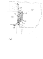
- Fig 4a and 4b show fragmentary sections through a can end and can body during formation of a first operation seam using tooling according to the invention.
- a chuck 106 supports the countersink wall 122 while the first operation seaming roll 112 is moved laterally towards the chuck 106.
- the countersink 122 has a depth C from the centre panel 120 to the seaming panel 124.
- the chuck lip 130 of the chuck 106 of the invention has an increased chuck lip height L measured, as shown, from the seaming panel 124 to the top of the chuck lip.
- the position of the first operation seaming roll 112 is raised so that the top of the chuck lip and the top surface of the first operation seaming profile 114 are inter-related, and are approximately at the same level. There are no changes to the first operation seaming roll.
- the widths of the seaming panel 124 and container flange 102 are standard.
- Fig 4b shows the first operation seam after forming with the modified chuck-roll relationship of the invention.
- the countersink 122 has increased depth C’ due to the space available in which the seam has been formed.
- Standard double seaming practice is that the seaming of steel ends requires space between the seaming roll profile and the seaming panel/curl.
- the Applicant has found that when forming a steel end of 0.10 to 0.14 gauge, low temper material, it is not necessary to contain the curl as it is possible to guide the can end by contact between the seaming roll and the end curl and still form satisfactory seams.
- the double seam 101 has been formed using a second operation seaming roll 117 with its profile adapted to give maximum area for seam growth.
- the face 115 of the second operation seaming roll is flat over most of its length and has tight radii at its ends.
- Both the second operation seaming roll surface and the working face of chuck lip (line Ch) are parallel and inclined at an angle, approximately 4° in this example. This angle is measured relative to a line P, which is perpendicular to the top of the chuck 106.
- a double seam developed using 0.13 low temper steel and formed in accordance with the method and apparatus of the present invention has been found to have good integrity and to meet all critical seaming parameters.
- Development samples passed helium leak testing at nominal, loose and tight settings, before and after overpressure processing. Internal end hook appearance was acceptable with a maximum tightness rating of 100%. Visually there was minimal or only slight waviness at the base of the seam but this did not affect seam integrity. Any waviness was considered to be an acceptable feature of seaming 0.13 material, giving substantial cost savings for reducing by over six gauges from standard end thicknesses (i.e. from 0.19 material).
Landscapes
- Engineering & Computer Science (AREA)
- Mechanical Engineering (AREA)
- Rigid Containers With Two Or More Constituent Elements (AREA)
Abstract
Method and apparatus for seaming containers is described, together with a double seam joining a flange of a container body and a container end wall. The method and apparatus use a chuck wall with a lip portion (130), which is increased in height and a second operation seaming roll (117) with a flat face. The minor changes to the seaming tooling (106, 117) enable the formation of double seams from a standard pressed end of thin gauge and low temper steel and a double reduced steel container body, which is substantially free of wrinkles.
Description
This invention relates to the seaming of containers, in particular forming a double seam between a container end and a container body. The container body is of steel, for example double reduced, and the steel end has a peripheral curl into which a flange on the container body is lifted and the seam is formed in two operations.
The seaming of aluminium containers and container bodies is well known for use in the manufacture of beverage cans. Such a process is described in WO 9723312 A CARNAUDMETALBOX and also in a patent by the same applicant, US 5911551 CARNAUDMETALBOX , in which relative rolling motion between the unseamed container (can) end and first and second operation rolls progressively forms first and second operation seams. In these documents, a preferred profile of first operation seaming roll, with specific radii, permits formation of small seams made of thin starting materials, e.g. less than 0.25 thickness aluminium or aluminium alloy. US 5911551 , for example, specifies the forming of a double seam of small dimensions with particular relevance to beverage cans and can ends formed from aluminium alloy sheet about 0.25 (0.010”) thick or tinplate or TFS (tin free steel) about 0.23 (0.009”) thick.
These prior art methods require the use of can ends, which are adapted for the formation of small seams from thin metal. The ends for seaming thus have a reduced end diameter, which reduces material used in formation of a seam formed using such an end. To achieve the small dimension seams of this prior art, new end press and associated tooling is required for pressing the initial ends.
In the manufacture of containers for packaging food products, the containers are generally manufactured from steel and the seamed container must often be able to withstand any differential pressures, which result from processing the product within the container. One method of minimising the differential pressure and strength requirement, is known as an “overpressure” retort where in-can pressure generated, additional to the vapour pressure of the steam (differential pressure) during the sterilisation process, may be balanced by the introduction of air pressure. This method is often used when the container is closed by a peelable end but may also be of use when sterilising specific food products in a container with standard diameter can ends.
Double seams for joining steel or double reduced (“DR”) steel container (can) bodies and steel ends are well known and are manufactured according to standard criteria. The seam, which has five layers of metal, must be sealed with lining compound to resist processing and abuse. Any seam, which is not sealed, offers a leakage path, which can allow micro-organisms to enter the can, resulting in product degradation or even food poisoning.
The reduction of metal thicknesses, or “downgauging” has increased the need for careful dimensional control to ensure a safe product. The use of thinner metals has led to an increase in wrinkles when forming the seam. Although these are often ironed out in the finished seam, there is a concern that evidence of the wrinkles in the finished seam still means that there is a potential leakage path.
Within the European Union an organisation called SEFEL has categorised seam dimensions to ensure interchangeability between food cans and ends from different sources. In addition to these SEFEL categories there are also specified critical seam dimensions required after the two operations for forming the double seam.
During the first operation, the end is curled into an inter-locking position with the can flange by pressure from a seaming roll. After the first operation, the seam is considered to be complete. The distance between the top of the seaming chuck lip and seaming roll entrance angle is considered to be critical to prevent metal being pushed over the chuck lip, which can lead to sharp seams and cut-overs, and poor control of countersink depth.
During the second operation, the five layers of metal, which were loosely interlocked in the first operation, are compressed and the seam is “ironed”. The second operation forces sealing compound into any void spaces in the double seam. There is also a requirement that the seam be free of visual defects. Such defects include the wrinkles, which were noted above as being potential leak paths.
Ends which are used for seaming to a double reduced (“DR”) steel body have standard features but are not generally of DR material since this is very stiff and prone to wrinkling in the seam. Wrinkles are associated with a lack of tightness in the double seam.
This invention seeks to provide a method and apparatus for downgauging the double seam of a steel container, whilst leaving the end press tooling and seaming roll profiles unchanged, in contrast with the prior art for manufacture of seams with small dimensions. The method and apparatus of the present invention is thus intended to be suitable for seaming tighter and smaller seams on a steel container, but without the tooling costs of US 5911551 or WO 9723312 .
According to the present invention, there is provided a method of forming a double seam between a flange of a container body formed from steel of from 0.10 to 0.15 gauge and a steel end including a peripheral curl, the method comprising the steps of: supporting the end on a chuck; moving a lifter to lift the flange of the can body into the peripheral curl of the end; applying a first operation tool to the periphery of the end progressively to form the end and to make a first operation seam; applying a second operation tool to flatten the first operation seam to form the complete double seam; wherein pressure is applied to the body throughout at least the first operation to encourage the body flange to become a body hook in the double seam; characterised in that: the end for forming into the double seam is 0.10 to 0.14 gauge, low temper material; and the method is characterised by: increasing the height of a chuck wall lip portion of the chuck, such that, in use, the lip is spaced from a seaming panel of the end by more than 0.1; applying the first operation tool against an upper part of the chuck lip portion, and reforming the end by drawing material from a seaming panel of the end into a countersink wall of the first operation seam; flattening the first operation seam to form the complete double seam by applying the face of the second operation tool at an angle to the vertical and substantially parallel to the chuck face; and ironing out any or substantially all visible wrinkles formed in the first operation seam by using the chuck and second operation roll to form a double seam.
Standard practice for the seaming of steel ends, considers that space is required within the seaming roll profile for containing the can end seaming panel/curl. The Applicant, however, has discovered that when the end material is low temper thin material, it is possible to use a seaming roll profile, which guides the seaming panel by contacting the curl. This is carried out in conjunction with increasing the chuck lip height. The present invention also irons the seam in the second operation by applying the face of the second operation roll at an angle, preferably about 4°.
Preferably, the lip is spaced from the seaming panel by at least 0.5 , which takes more material out of the standard seaming panel and reduces or avoids wrinkling further.
According to another aspect of the present invention, there is provided an apparatus for forming a double seam between a flange of a container body formed from steel of from 0.10 to 0.15 gauge and a steel end including a peripheral curl, the apparatus comprising: a chuck to support the end; a lifter to lift the flange of the body into the peripheral curl; a first operation tool moveable towards and away from the periphery of the end wall to form the end and to form a first operation seam; a second operation tool moveable towards and away from the periphery of the end wall to flatten the first operation seam and to complete the double seam; and lifting means to apply compressive pressure in an axial direction to the body during at least the first operation of seaming; characterised in that the steel end for forming into the double seam is 0.10 to 0.14 gauge, low temper material; the chuck includes an increased height cylindrical lip portion, the height of the lip portion being such that, in use, the lip is spaced from a seaming panel of the end by more than 0.1; the first operation seaming roll is set at a position adjacent an upper part of the chuck lip; and the second operation roll has a flat surface which is inclined at an angle to the vertical (upright) position; whereby any wrinkles formed in the first operation seam are substantially ironed out by the chuck and second operation roll to form a double seam which has minimal or no visible wrinkling.
Preferably, the lip is spaced from the seaming panel by at least 0.5 , which takes more material out of the standard seaming panel and reduces or avoids wrinkling further.
The angle of the second operation roll flat surface preferably matches the angle of the chuck lip, and these may ideally be about 4° so that the surfaces of the roll and chuck lip are substantially parallel.
The method and apparatus of the present invention involve minor modifications to the seaming chuck but otherwise no first operation tooling or press changes. The chuck lip height is increased but the first operation seaming roll is standard, making contact at a higher position. Typically the second operation roll has a flat face with tight radii at both ends. It is therefore possible in the present invention to form a seam from thinner low temper material with minimal changes to existing food can end tooling.
Whilst it was previously thought impossible to seam soft, low temper material without excessive wrinkling and potential leakage in the finished seam, the method and apparatus of the present invention provide a balance between end hook wrinkling, sharp corners and waviness, whilst maintaining the critical seam dimensions noted above.
According to yet another aspect of the present invention, there is provided a double seam joining a flange of a container body formed from double reduced steel of from 0.10 to 0.15 gauge and a steel end wall including a peripheral curl, in which the end wall is formed from a steel end of 0.10 to 0.14 gauge, low temper material, and has a centre panel within the peripheral curl; the double seam is inclined at an angle of 4° to an axis perpendicular to the centre panel; and the double seam is substantially free of wrinkles.
Preferred embodiments of the invention will now be described, by way of example, with reference to the drawings, in which:
Figures 1a to 1d are diagrammatic side views of known seam forming apparatus at various stages in the formation of a double seam;
Figures 2a and 2b are fragmentary sections through a can end and can body during formation of a known first operation seam;
Figures 3a and 3b are fragmentary sections through a can end and can body during formation of a known second operation seam;
Figures 4a and 4b are fragmentary sections through a can end and can body during formation of a first operation seam using tooling according to the invention; and
Figure 5 is a fragmentary section through a can end and can body during formation of a finished seam using second operation tooling according to the invention.
Figures 2a and 2b are fragmentary sections through a can end and can body during formation of a known first operation seam;
Figures 3a and 3b are fragmentary sections through a can end and can body during formation of a known second operation seam;
Figures 4a and 4b are fragmentary sections through a can end and can body during formation of a first operation seam using tooling according to the invention; and
Figure 5 is a fragmentary section through a can end and can body during formation of a finished seam using second operation tooling according to the invention.
Fig 1 shows known prior art apparatus for forming a double seam 1 between a flange 2 of a container body 3 and an end wall 4 having a peripheral curl 5. This apparatus has a chuck to support the end wall 4, a movable lifter 7 axially aligned with the chuck to lift the flange 2 of the can body into the peripheral curl 5 of the end wall 4.
Although seaming apparatus is known in which the can does not rotate, in this particular example the chuck is driven to rotate in a turret 10 and the lifter 7 is freely mounted for rotation on a spring 8 in a follower 9 mounted in the turret 10. If desired, the lifter may be driven to rotate at the same speed as the chuck.
The follower 9 is urged to rise and fall by a cam 11 as the turret rotates from positions (a) to (d) in Fig 1.
A first operation seaming roll 12 is supported for free rotation on a pivotable arm 13 which holds a first operation seaming profile 14 of the roll at a level to receive the peripheral curl 5 of the can end as the first operation roll is swung in to progressively generate the first operation seam of Figs 1b and Fig 2b from the assembled body and can end as shown in Fig 2a.
As shown in Fig 1a the follower has moved from a low portion of the cam 11 at which the can end and body are assembled between the chuck and lifter, to a higher position at which the can end is firmly clamped onto the body flange 2. The lifting force on the follower 9 is delivered through spring 8 to the lifter 7 so that the can and end assembly is resiliently clamped under a known pressure imposed by the cam in the axial direction.
As the turret moves from the position shown in Fig 1b the cam 11 causes the follower 9 to rise further so increasing pressure on the spring 8 which causes the lifter to rise to lift the can body so feeding flange material into the curl to generate the first operation seam shown in Fig 2b.
Comparing Fig 2a with Fig 2b it will be seen that the profile of the first operation roll has progressively turned in the end curl 5 to turn in between the turned down body flange 2 and the body wall 26. The free edge of the flange (now also referred to as body hook) 2 is bedded in a lining compound 25 without scraping it off the can end curl. This ideal configuration is achieved by controlled placement of the lining compound 25 in the curl 5 of the can end and controlled lifter pressure.
Fig 1c shows the apparatus at commencement of a second operation to complete a double seam. The cam 11 has raised the follower 9 from the position shown in Fig 1b and Fig 3(a) to continue to apply a compressive pressure on the body and end.
A second operation seaming roll 17 is supported for free rotation on a pivotable arm 16 which holds a second operation seam forming profile 15 at a level to receive the first operation seam as the arm is swung-in to progressively flatten the first operation seam and to complete a double seam 1 as shown in Figs 3(b) and 1(d).
After completion of the double seam the cam 11 lowers the lifter to release the seamed can for removal.
Fig 2a shows a peripheral portion of a can end 4 resting on the flange 2 of a can body 3 at commencement of a first operation of double seaming.
The can end 4 comprises a centre panel 20, a countersink wall 22 joined to the centre panel by a countersink wall radius 21, a seaming panel 24 joined to the countersink wall by a seaming panel radius 23, and a peripheral curl 5. An annulus of lining compound 25 extends around the inside of the curl 5. The can body 3 comprises a sidewall portion 26, and t flange 2 joined to the sidewall by a flange radius 27.
In Fig 2a a chuck 6 supports the countersink wall 22 while the first operation seaming roll 12 is moved laterally towards the chuck 6 so that the profile 14 of the first operation roll turns the seaming panel downwards and the curl 5 inwards and upwards to extend between the sidewall portion and the turned down flange or body hook as shown in Fig 2b.
Fig 2b shows a preferred form of first operation seam in which the turned down flange or body hook 2 is bedded in the annulus of lining compound 25 and the free edge of the end curl (now also referred to as cover hook) 5 reaches well up into the gap between the sidewall portion 26 and the turned-down flange 2. This configuration of first operation seam reforms well in the second operation of seaming to achieve adequate overlaps of body flange/hook 2 and end curl/cover hook 5, and subsequent seam tightness in the finished seam.
If there were excess metal on the first operation seam, the seaming panel radius 23 could be bent to a tighter radius, which would then stand proud of the bent down flange radius. Excess metal in the first operation seam may give rise to a short end hook, excessive seam length or pleating (corrugation) during the second operation. The "slack" metal of panel radius may even be pushed inwards and disturbs the chuck wall fit in the sidewall.
Fig 2b shows a first operation seam made according to known seaming processes. The pressure applied by cam 11 has been passed through the sidewall portion 26 to feed sidewall metal into the first operation seam so tightening the body flange radius 27 to fit the seaming panel radius 23. It is essential that the free edge 29 of the cover hook in the first operation seam is not in contact with the side wall 26 and must be outboard of the arcuate surface 28.
Fig 3b shows the completed double seam 1 after the second operation roll 17 has cooperated with the chuck 6 (Fig 3a) so as progressively to flatten the arcuate surface of the first operation seam, reducing any wrinkles and generate the double seam 2 by crushing the first operation seam of Fig 2c. As can be seen in Fig 3b, the can end and body hooks 5, 2 overlap tightly, with lining compound 25 filling any voids and covering “exposed” metal at the ends of both hooks.
Fig 4a and 4b show fragmentary sections through a can end and can body during formation of a first operation seam using tooling according to the invention. In Fig 4a a chuck 106 supports the countersink wall 122 while the first operation seaming roll 112 is moved laterally towards the chuck 106.
In Fig 4a, it can be seen that the countersink 122 has a depth C from the centre panel 120 to the seaming panel 124. The chuck lip 130 of the chuck 106 of the invention has an increased chuck lip height L measured, as shown, from the seaming panel 124 to the top of the chuck lip. The position of the first operation seaming roll 112 is raised so that the top of the chuck lip and the top surface of the first operation seaming profile 114 are inter-related, and are approximately at the same level. There are no changes to the first operation seaming roll. The widths of the seaming panel 124 and container flange 102 are standard.
Fig 4b shows the first operation seam after forming with the modified chuck-roll relationship of the invention. The countersink 122 has increased depth C’ due to the space available in which the seam has been formed. Standard double seaming practice is that the seaming of steel ends requires space between the seaming roll profile and the seaming panel/curl. However, the Applicant has found that when forming a steel end of 0.10 to 0.14 gauge, low temper material, it is not necessary to contain the curl as it is possible to guide the can end by contact between the seaming roll and the end curl and still form satisfactory seams.
In Fig 5, the double seam 101 has been formed using a second operation seaming roll 117 with its profile adapted to give maximum area for seam growth. To do this, the face 115 of the second operation seaming roll is flat over most of its length and has tight radii at its ends. Both the second operation seaming roll surface and the working face of chuck lip (line Ch) are parallel and inclined at an angle, approximately 4° in this example. This angle is measured relative to a line P, which is perpendicular to the top of the chuck 106.
A double seam developed using 0.13 low temper steel and formed in accordance with the method and apparatus of the present invention has been found to have good integrity and to meet all critical seaming parameters. Development samples passed helium leak testing at nominal, loose and tight settings, before and after overpressure processing. Internal end hook appearance was acceptable with a maximum tightness rating of 100%. Visually there was minimal or only slight waviness at the base of the seam but this did not affect seam integrity. Any waviness was considered to be an acceptable feature of seaming 0.13 material, giving substantial cost savings for reducing by over six gauges from standard end thicknesses (i.e. from 0.19 material).
The Applicant has found that small profile double seams formed from thinner softer materials, as described above, maintain standard double seam critical dimensions and have substantially no or acceptable levels of wrinkling. These small profile double seams typically have the same dimensions as those formed using apparatus and non-standard pressed ends and seamer tooling as described in prior art documents US 5911551 and WO 9723312 but with substantially less capital costs
1 double seam
2 body flange
3 container body
4 end
5 peripheral curl
6 chuck
7 lifter
8 spring
9 follower
10 turret
11 cam
12 1st op seaming roll
13 pivotable arm
14 1st op seaming profile
15 2nd op seaming profile
16 pivotable arm
17 2nd op seaming roll
20 centre panel
21 countersink wall radius
22 countersink wall
23 seaming panel radius
24 seaming panel
25 lining compound
26 container sidewall
27 body flange radius
28 end curl
29 free edge of cover hook
2 body flange
3 container body
4 end
5 peripheral curl
6 chuck
7 lifter
8 spring
9 follower
10 turret
11 cam
12 1st op seaming roll
13 pivotable arm
14 1st op seaming profile
15 2nd op seaming profile
16 pivotable arm
17 2nd op seaming roll
20 centre panel
21 countersink wall radius
22 countersink wall
23 seaming panel radius
24 seaming panel
25 lining compound
26 container sidewall
27 body flange radius
28 end curl
29 free edge of cover hook
101 double seam
102 flange
106 chuck
112 1st op seaming roll
114 1st op seaming roll profile
115 2nd op seaming profile
117 2nd op seaming roll
122 countersink wall
124 seaming panel
130 chuck lip
102 flange
106 chuck
112 1st op seaming roll
114 1st op seaming roll profile
115 2nd op seaming profile
117 2nd op seaming roll
122 countersink wall
124 seaming panel
130 chuck lip
C countersink depth
C’ increased countersink depth
L increased chuck lip height
P perpendicular line
Ch line at working face of chuck lip
R roll face
C’ increased countersink depth
L increased chuck lip height
P perpendicular line
Ch line at working face of chuck lip
R roll face
Claims (8)
- A method of forming a double seam between a flange of a container body formed from steel of from 0.10 to 0.15 gauge and a steel end including a peripheral curl,the method comprising the steps of:supporting the end on a chuck;moving a lifter to lift the flange of the can body into the peripheral curl of the end;applying a first operation tool to the periphery of the end progressively to form the end and to make a first operation seam;applying the face of a second operation tool to flatten the first operation seam to form the complete double seam;wherein pressure is applied to the body throughout at least the first operation to encourage the body flange to become a body hook in the double seam;characterised in that:the end for forming into the double seam is 0.10 to 0.14 gauge, low temper material; andthe method is characterised by:increasing the height of a chuck wall lip portion of the chuck, such that, in use, the lip is spaced from a seaming panel of the end by more than 0.1;applying the first operation tool against an upper part of the chuck lip portion, and reforming the end by drawing material from a seaming panel of the end into a countersink wall of the first operation seam;flattening the first operation seam to form the complete double seam by applying the face of the second operation tool at an angle to the vertical (upright) position; andironing out any or substantially all wrinkles formed in the first operation seam by using the chuck and second operation roll to form a double seam.
- A method according to claim 1, comprising applying the face of the second operation tool at an angle of 4°, and substantially parallel to the face of the chuck.
- A method according to claim 1 or claim 2, in which, in use, the lip is spaced from a seaming panel of the end by at least 0.5 .
- An apparatus for forming a double seam between a flange of a container body formed from double reduced steel of from 0.10 to 0.15 gauge and a steel end including a peripheral curl, the apparatus comprising:a chuck to support the end;a lifter to lift the flange of the body into the peripheral curl;a first operation tool moveable towards and away from the periphery of the end wall to reform the end by drawing material from a curl region of the end into a countersink wall of a first operation seam;a second operation tool moveable towards and away from the periphery of the end wall to flatten the first operation seam and to complete the double seam; andlifting means to apply compressive pressure in an axial direction to the body during at least the first operation of seaming;characterised in thatthe steel end for forming into the double seam is 0.10 to 0.14 gauge, low temper material;the chuck includes an increase height cylindrical lip portion, the height of the lip portion being such that, in use, the lip is spaced from a seaming panel of the end by more than 0.1;the first operation seaming roll is set at a position adjacent an upper part of the chuck lip; andthe second operation roll has a flat surface which is inclined at an angle to the vertical (upright) position;whereby any wrinkles formed in the first operation seam are substantially ironed out by the chuck and second operation roll to form a double seam which has minimal or no wrinkling.
- An apparatus according to claim 4, in which the angle of the face of the second operation roll is 4°.
- An apparatus according to claim 5, in which the angle of the face of the chuck lip is substantially parallel to the face of the second operation roll.
- An apparatus according to any one of claims 4 to 6, in which, in use, the lip is spaced from a seaming panel of the end by at least 0.5 .
- A double seam joining a flange of a container body formed from double reduced steel of from 0.12 to 0.15 gauge and a steel end wall including a peripheral curl, in whichthe end wall is formed from a steel end of 0.10 to 0.14 gauge, low temper material, and has a centre panel within the peripheral curl;the double seam is inclined at an angle of 4° to an axis perpendicular to the centre panel; andthe double seam is substantially free of wrinkles.
Applications Claiming Priority (2)
| Application Number | Priority Date | Filing Date | Title |
|---|---|---|---|
| EP11162769.1 | 2011-04-18 | ||
| EP11162769 | 2011-04-18 |
Publications (1)
| Publication Number | Publication Date |
|---|---|
| WO2012143263A1 true WO2012143263A1 (en) | 2012-10-26 |
Family
ID=45974324
Family Applications (1)
| Application Number | Title | Priority Date | Filing Date |
|---|---|---|---|
| PCT/EP2012/056460 Ceased WO2012143263A1 (en) | 2011-04-18 | 2012-04-10 | Method and apparatus for seaming containers and double seam thereby obtained |
Country Status (1)
| Country | Link |
|---|---|
| WO (1) | WO2012143263A1 (en) |
Cited By (3)
| Publication number | Priority date | Publication date | Assignee | Title |
|---|---|---|---|---|
| CN106734713A (en) * | 2017-03-20 | 2017-05-31 | 山东胜宁电器有限公司 | A kind of cup processing method |
| CN106807850A (en) * | 2017-03-20 | 2017-06-09 | 山东胜宁电器有限公司 | Container finish press fit device and equipment |
| USD1068472S1 (en) | 2023-05-01 | 2025-04-01 | C-Loop Packaging Sweden Ab | Can end |
Citations (4)
| Publication number | Priority date | Publication date | Assignee | Title |
|---|---|---|---|---|
| EP0664171A1 (en) * | 1994-01-19 | 1995-07-26 | Schmalbach-Lubeca AG | Tool for closing machine |
| WO1997023312A1 (en) | 1995-12-23 | 1997-07-03 | Carnaudmetalbox Plc | Containers |
| US5911551A (en) | 1994-07-20 | 1999-06-15 | Carnaudmetalbox Plc | Containers |
| US20040074911A1 (en) * | 2001-07-03 | 2004-04-22 | Container Development, Ltd. | Can shell and double-seamed can end |
-
2012
- 2012-04-10 WO PCT/EP2012/056460 patent/WO2012143263A1/en not_active Ceased
Patent Citations (4)
| Publication number | Priority date | Publication date | Assignee | Title |
|---|---|---|---|---|
| EP0664171A1 (en) * | 1994-01-19 | 1995-07-26 | Schmalbach-Lubeca AG | Tool for closing machine |
| US5911551A (en) | 1994-07-20 | 1999-06-15 | Carnaudmetalbox Plc | Containers |
| WO1997023312A1 (en) | 1995-12-23 | 1997-07-03 | Carnaudmetalbox Plc | Containers |
| US20040074911A1 (en) * | 2001-07-03 | 2004-04-22 | Container Development, Ltd. | Can shell and double-seamed can end |
Cited By (4)
| Publication number | Priority date | Publication date | Assignee | Title |
|---|---|---|---|---|
| CN106734713A (en) * | 2017-03-20 | 2017-05-31 | 山东胜宁电器有限公司 | A kind of cup processing method |
| CN106807850A (en) * | 2017-03-20 | 2017-06-09 | 山东胜宁电器有限公司 | Container finish press fit device and equipment |
| CN106734713B (en) * | 2017-03-20 | 2018-09-18 | 山东胜宁电器有限公司 | A kind of cup body processing method |
| USD1068472S1 (en) | 2023-05-01 | 2025-04-01 | C-Loop Packaging Sweden Ab | Can end |
Similar Documents
| Publication | Publication Date | Title |
|---|---|---|
| CA1280701C (en) | Method and apparatus for forming end panels for containers and end panels formed thereby | |
| US5911551A (en) | Containers | |
| US5704240A (en) | Method and apparatus for forming threads in metal containers | |
| US3964413A (en) | Methods for necking-in sheet metal can bodies | |
| US9334078B2 (en) | Can manufacture | |
| EP0497346B1 (en) | Pressure resistant sheet metal end closure | |
| US5957647A (en) | Containers | |
| EP1603802B1 (en) | Seaming apparatus and method for cans | |
| IE851182L (en) | Sealing canisters | |
| CN101227987A (en) | Method and apparatus for forming a reinforcing bead in a container end closure | |
| CA2787546C (en) | Can manufacture | |
| US4264017A (en) | Container shape | |
| WO2012143263A1 (en) | Method and apparatus for seaming containers and double seam thereby obtained | |
| US7772518B2 (en) | Reinforced can end—can body joints with laser seaming | |
| JPH0773766B2 (en) | Can shell | |
| HUE031786T2 (en) | Process for closing metal cans | |
| IE840905L (en) | Crimping a metal closure | |
| JP7261228B2 (en) | Method of forming roll edges | |
| US4372719A (en) | Annealing of end rim | |
| JPH04220125A (en) | End surface of can | |
| US3416476A (en) | Container closure seaming method and apparatus | |
| CN212551195U (en) | Can body curling device | |
| US20140197181A1 (en) | Three-piece can | |
| CN111702096A (en) | Forming equipment and forming process of threaded tank body | |
| WO1997023312A1 (en) | Containers |
Legal Events
| Date | Code | Title | Description |
|---|---|---|---|
| 121 | Ep: the epo has been informed by wipo that ep was designated in this application |
Ref document number: 12714672 Country of ref document: EP Kind code of ref document: A1 |
|
| NENP | Non-entry into the national phase |
Ref country code: DE |
|
| 122 | Ep: pct application non-entry in european phase |
Ref document number: 12714672 Country of ref document: EP Kind code of ref document: A1 |