WO2012137843A1 - Generator apparatus for aircraft - Google Patents
Generator apparatus for aircraft Download PDFInfo
- Publication number
- WO2012137843A1 WO2012137843A1 PCT/JP2012/059246 JP2012059246W WO2012137843A1 WO 2012137843 A1 WO2012137843 A1 WO 2012137843A1 JP 2012059246 W JP2012059246 W JP 2012059246W WO 2012137843 A1 WO2012137843 A1 WO 2012137843A1
- Authority
- WO
- WIPO (PCT)
- Prior art keywords
- transmission
- shaft
- generator
- engine
- input shaft
- Prior art date
Links
Images


Classifications
-
- F—MECHANICAL ENGINEERING; LIGHTING; HEATING; WEAPONS; BLASTING
- F16—ENGINEERING ELEMENTS AND UNITS; GENERAL MEASURES FOR PRODUCING AND MAINTAINING EFFECTIVE FUNCTIONING OF MACHINES OR INSTALLATIONS; THERMAL INSULATION IN GENERAL
- F16H—GEARING
- F16H15/00—Gearings for conveying rotary motion with variable gear ratio, or for reversing rotary motion, by friction between rotary members
-
- F—MECHANICAL ENGINEERING; LIGHTING; HEATING; WEAPONS; BLASTING
- F02—COMBUSTION ENGINES; HOT-GAS OR COMBUSTION-PRODUCT ENGINE PLANTS
- F02C—GAS-TURBINE PLANTS; AIR INTAKES FOR JET-PROPULSION PLANTS; CONTROLLING FUEL SUPPLY IN AIR-BREATHING JET-PROPULSION PLANTS
- F02C7/00—Features, components parts, details or accessories, not provided for in, or of interest apart form groups F02C1/00 - F02C6/00; Air intakes for jet-propulsion plants
- F02C7/36—Power transmission arrangements between the different shafts of the gas turbine plant, or between the gas-turbine plant and the power user
-
- F—MECHANICAL ENGINEERING; LIGHTING; HEATING; WEAPONS; BLASTING
- F02—COMBUSTION ENGINES; HOT-GAS OR COMBUSTION-PRODUCT ENGINE PLANTS
- F02C—GAS-TURBINE PLANTS; AIR INTAKES FOR JET-PROPULSION PLANTS; CONTROLLING FUEL SUPPLY IN AIR-BREATHING JET-PROPULSION PLANTS
- F02C7/00—Features, components parts, details or accessories, not provided for in, or of interest apart form groups F02C1/00 - F02C6/00; Air intakes for jet-propulsion plants
- F02C7/26—Starting; Ignition
- F02C7/268—Starting drives for the rotor, acting directly on the rotor of the gas turbine to be started
- F02C7/275—Mechanical drives
-
- F—MECHANICAL ENGINEERING; LIGHTING; HEATING; WEAPONS; BLASTING
- F02—COMBUSTION ENGINES; HOT-GAS OR COMBUSTION-PRODUCT ENGINE PLANTS
- F02C—GAS-TURBINE PLANTS; AIR INTAKES FOR JET-PROPULSION PLANTS; CONTROLLING FUEL SUPPLY IN AIR-BREATHING JET-PROPULSION PLANTS
- F02C7/00—Features, components parts, details or accessories, not provided for in, or of interest apart form groups F02C1/00 - F02C6/00; Air intakes for jet-propulsion plants
- F02C7/32—Arrangement, mounting, or driving, of auxiliaries
-
- F—MECHANICAL ENGINEERING; LIGHTING; HEATING; WEAPONS; BLASTING
- F05—INDEXING SCHEMES RELATING TO ENGINES OR PUMPS IN VARIOUS SUBCLASSES OF CLASSES F01-F04
- F05D—INDEXING SCHEME FOR ASPECTS RELATING TO NON-POSITIVE-DISPLACEMENT MACHINES OR ENGINES, GAS-TURBINES OR JET-PROPULSION PLANTS
- F05D2260/00—Function
- F05D2260/40—Transmission of power
- F05D2260/403—Transmission of power through the shape of the drive components
- F05D2260/4031—Transmission of power through the shape of the drive components as in toothed gearing
-
- F—MECHANICAL ENGINEERING; LIGHTING; HEATING; WEAPONS; BLASTING
- F05—INDEXING SCHEMES RELATING TO ENGINES OR PUMPS IN VARIOUS SUBCLASSES OF CLASSES F01-F04
- F05D—INDEXING SCHEME FOR ASPECTS RELATING TO NON-POSITIVE-DISPLACEMENT MACHINES OR ENGINES, GAS-TURBINES OR JET-PROPULSION PLANTS
- F05D2260/00—Function
- F05D2260/50—Kinematic linkage, i.e. transmission of position
- F05D2260/53—Kinematic linkage, i.e. transmission of position using gears
- F05D2260/532—Kinematic linkage, i.e. transmission of position using gears of the bevelled or angled type
-
- F—MECHANICAL ENGINEERING; LIGHTING; HEATING; WEAPONS; BLASTING
- F05—INDEXING SCHEMES RELATING TO ENGINES OR PUMPS IN VARIOUS SUBCLASSES OF CLASSES F01-F04
- F05D—INDEXING SCHEME FOR ASPECTS RELATING TO NON-POSITIVE-DISPLACEMENT MACHINES OR ENGINES, GAS-TURBINES OR JET-PROPULSION PLANTS
- F05D2270/00—Control
- F05D2270/01—Purpose of the control system
- F05D2270/02—Purpose of the control system to control rotational speed (n)
- F05D2270/024—Purpose of the control system to control rotational speed (n) to keep rotational speed constant
-
- F—MECHANICAL ENGINEERING; LIGHTING; HEATING; WEAPONS; BLASTING
- F05—INDEXING SCHEMES RELATING TO ENGINES OR PUMPS IN VARIOUS SUBCLASSES OF CLASSES F01-F04
- F05D—INDEXING SCHEME FOR ASPECTS RELATING TO NON-POSITIVE-DISPLACEMENT MACHINES OR ENGINES, GAS-TURBINES OR JET-PROPULSION PLANTS
- F05D2270/00—Control
- F05D2270/30—Control parameters, e.g. input parameters
- F05D2270/304—Spool rotational speed
-
- Y—GENERAL TAGGING OF NEW TECHNOLOGICAL DEVELOPMENTS; GENERAL TAGGING OF CROSS-SECTIONAL TECHNOLOGIES SPANNING OVER SEVERAL SECTIONS OF THE IPC; TECHNICAL SUBJECTS COVERED BY FORMER USPC CROSS-REFERENCE ART COLLECTIONS [XRACs] AND DIGESTS
- Y02—TECHNOLOGIES OR APPLICATIONS FOR MITIGATION OR ADAPTATION AGAINST CLIMATE CHANGE
- Y02T—CLIMATE CHANGE MITIGATION TECHNOLOGIES RELATED TO TRANSPORTATION
- Y02T50/00—Aeronautics or air transport
- Y02T50/60—Efficient propulsion technologies, e.g. for aircraft
Definitions
- the present invention relates to an aircraft power generation apparatus that is connected to an aircraft engine and drives a generator.
- power generators for large aircraft use a continuously variable transmission to generate power at a constant frequency by rotating the generator at a constant speed regardless of the engine speed.
- a drive mechanism-integrated power generation device) type is known.
- the IDG power generator is combined with a traction continuously variable transmission and a planetary gear transmission to compensate for its low mechanical efficiency, and the transmission power is distributed between these transmissions by a power diverting shaft.
- a power split type constant speed drive device is known (see Patent Document 1).
- aircraft engines often have a two-shaft type that includes a hollow high-pressure shaft that connects a compressor and a high-pressure turbine, and a low-pressure shaft that is inserted into the high-pressure shaft and connects a fan and a low-pressure turbine. It has been adopted.
- the planetary gear transmission operates at a fixed gear ratio, so that the gear ratio of the entire constant speed driving device is within about 2: 1. Therefore, in the case of the two-shaft type, the input shaft of the constant speed drive device is connected to a high-pressure shaft with little fluctuation in the rotational speed.
- the output of the conventional IDG type power generation apparatus is about 90 kVA, but in recent aircraft, a large power generation capacity of 200 kVA or more is required with the progress of electrification.
- a large-capacity power generation is performed, if the power generator is connected to the high-pressure shaft of the aircraft engine as described above, there is a problem in the operation of the high-pressure shaft system when the electrical load of the aircraft increases ( (Stall) is generated, which is not preferable.
- an aircraft power generation device that is driven by rotation transmission of a low-pressure shaft without load limitation has been proposed (see Patent Document 2).
- a transmission and a generator (not shown) inside the power generator 75 are arranged in the direction of the engine axis C and aligned with each other in the vertical direction.
- the present invention suppresses an increase in the area of the front surface of an aircraft engine without separately providing an accessory, gear box, etc., even in the case of performing large capacity power generation driven by a low pressure shaft.
- An object is to provide an aircraft power generator that can be attached.
- an aircraft power generator is a power generator driven by an aircraft engine, and includes a transmission coupled to a rotation shaft of the engine, and an output of the transmission.
- a transmission mechanism for driving the transmission around the center, and the transmission and the generator are spaced apart in the circumferential direction of the rotating shaft.
- the input shaft has an axial center along the radial direction of the rotary shaft, and the transmission mechanism drives the transmission around an axial center in a direction orthogonal to the input shaft.
- the rotation of the input shaft arranged along the direction intersecting with the rotation axis of the engine is converted into the rotation around the axis center in the direction intersecting with the input shaft by the transmission mechanism and transmitted to the transmission. Therefore, the transmission can be provided in an arrangement substantially along the front-rear direction of the aircraft engine. Further, the transmission and the generator are arranged apart from each other in the circumferential direction of the rotating shaft, that is, in the vertical direction.
- the power generator as a whole is preferably suitable for a vertically long (long in the circumferential direction) and thin slim shape as seen from the axial direction of the engine, that is, in a state where there is little protrusion from the side of the aircraft engine. It becomes a shape that can be attached, and it is possible to suppress a decrease in fuel consumption by suppressing an increase in air resistance of the aircraft.
- the rotation of the input shaft that intersects the rotation axis of the engine is converted into rotation around the axis in the direction that intersects the input shaft by the transmission mechanism. Even if it is set as the structure driven by this, it can achieve without providing an accessory gear box separately. Therefore, an increase in weight, an increase in cost, an increase in air resistance, and a decrease in reliability due to the addition of an accessory gear box can be suppressed.
- the input shaft is disposed between the transmission and the generator in the circumferential direction.
- the input shaft is located between the relatively heavy transmission and the generator, that is, close to the center of gravity of the power generator.
- the mounting surface of the power generation device to the aircraft engine is arranged so as to surround the input shaft. However, since the input shaft is close to the center of gravity, the overhang moment of the power generation device with respect to this mounting surface is reduced, and the power generation device for aircraft Installation on the engine is stabilized.
- the transmission and the generator have axes parallel to each other, and at least a part of the axial direction positions overlap each other.
- the shaft center of the transmission and the generator are parallel to each other, it can be gear-coupled with a spur gear, so the structure can be simplified and at least a part of the axial direction positions overlap each other.
- the axial length of the power generator can be shortened.
- the power generator is driven by an engine including a low pressure shaft for driving a fan and a high pressure shaft for driving a compressor, and the rotary shaft is the low pressure shaft.
- the power generation device is driven to rotate by the low-pressure shaft with a small limit on the take-off load, unlike the high-pressure shaft that has a limit on the take-out load in order to prevent engine stall.
- the transmission is preferably a traction continuously variable transmission.
- a traction continuously variable transmission it is possible to cope with a large change in the gear ratio, and therefore, large-capacity power generation can be easily realized even when connected to a low-pressure shaft having a large rotational fluctuation.
- the trunkion continuously variable transmission may be a double cavity type, and an input part may be provided in the middle part in the axial direction, and an output part may be provided on the outside thereof.
- the transmission mechanism input shaft connected to the transmission input portion via the transmission mechanism is disposed in the middle portion in the axial direction of the transmission, so that the transmission mechanism input shaft is located at the center of gravity of the generator. It becomes easy to approach, and the above-mentioned overhang moment becomes small.
- a case that houses the transmission and the generator has an opening that penetrates the input shaft and a flange that surrounds the periphery of the opening, and the case is attached to the engine via the flange. It is preferable that As a result, with the input shaft that protrudes through the opening of the case connected to the rotation shaft of the engine, the flanges that surround the opening of the case are fixed to each other in an overlapped manner on the flange of the engine, for example. By the means, the power generator can be stably attached to the engine by an easy attachment operation.
- an intermediate gear for gearing between the transmission and the generator is further provided.
- the rotation of the transmission can be transmitted to the generator in an accelerated or decelerated state via the intermediate gear, so that both the transmission and the generator can be driven at an appropriate rotational speed, and the rotation of the transmission can be It is possible to prevent the occurrence of a large mechanical loss as in the case where the speed is increased and transmitted to the rotational speed for driving the generator.
- the pump can be driven using the rotation of the intermediate gear, and a dedicated drive system for driving the pump becomes unnecessary.
- the lubricating oil can be supplied to the lubrication target portion with a simplified configuration. .
- the shaft centers of the transmission and the generator are parallel to the rotation axis of the engine.
- the shaft center of the transmission and the generator are arranged in parallel with the rotation shaft arranged in the front-rear direction of the engine, so that the cross-sectional area (front surface area) in the direction perpendicular to the rotation axis is reduced.
- the shape of the nacelle covering the aircraft engine can be a suitable shape that suppresses an increase in the front area of the engine.
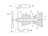
- FIG. 1 is a configuration diagram schematically showing a connection state of an aircraft power generation device 1 according to a first embodiment of the present invention to an engine E.
- the engine E is a two-shaft fan engine, and includes a compressor 2, a combustor 3, a turbine 4, and a fan 10 as main components. Fuel is mixed with compressed air supplied from the compressor 2 and burned in the combustor 3, and high-temperature and high-pressure combustion gas generated by the combustion is supplied to the turbine 4.
- the turbine 4 has a front-side high-pressure turbine 41 and a rear-side low-pressure turbine 42, and the compressor 2 is connected to the high-pressure turbine 41 through a hollow high-pressure shaft 7, and is driven to rotate by the high-pressure turbine 41. Is done.
- the fan 10 is connected to a low-pressure turbine 42 through a low-pressure shaft 9 inserted through a hollow portion of the high-pressure shaft 7, and is driven to rotate by the low-pressure turbine 42.
- the high pressure shaft 7 and the low pressure shaft 9 have a concentric arrangement with a common engine shaft center C. Thus, engine thrust is obtained by the jet flow of the combustion gas injected from the low-pressure turbine 42 and the high-speed air flow generated by the fan 10.
- a bevel gear 8A is provided behind the fan 10 in the low pressure shaft 9, and a bevel gear 8B meshing with the bevel gear 8A is provided at one end of the first connecting shaft 11 extending in the radial direction of the low pressure shaft 9. .
- An input shaft (transmission mechanism input shaft), which will be described later, of the power generation device 1 is connected to the other end portion of the first connection shaft 11, and the power generation device 1 is driven by rotation transmission from the low pressure shaft 9. Yes.
- the high pressure shaft 7 is used as the rotating shaft of the engine E that drives the power generation apparatus 1. Used as a rotating shaft to drive.
- the first connecting shaft 11 has an axial center along the radial direction of the low pressure shaft 9 which is one of the engine rotating shafts.
- the other end of the first connecting shaft 11 is shown in FIG. It is directly connected to the input shaft of the power generator 1 of FIG. 1 without interposing an accessory gear box 73 as in the conventional apparatus.
- the power generator 1 is attached to the fan case FC of the engine E via the attachment pad 12, and details thereof will be described later.
- one end portion of the second connecting shaft 14 is gear-connected to the front end of the high-pressure shaft 7 via bevel gears 13A and 13B meshing with each other, and the other end of the second connecting shaft 14 is connected.
- An accessory gear box (AGB) 19 for driving an auxiliary machine 18 such as a fuel pump is connected to the section.
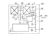
- FIG. 2 which is a schematic diagram showing a schematic configuration of the power generation device 1
- one end portion is directly connected to the first connection shaft 11 of the engine E on the input side of the power generation device 1 and extends in the radial direction R (FIG. 1).
- a transmission mechanism input shaft 27 and a transmission mechanism that is connected to the transmission mechanism input shaft 27 and that drives the transmission 22 about the axis in the direction orthogonal to the first connection shaft 11 (in this example, the direction of the engine axis C). 21 is disposed.
- the input shaft 27 is not limited to the one extending in the radial direction R (FIG. 1), and may be slightly inclined from the radial direction R. That is, the input shaft 27 is included in the present invention as long as it has an axis along the direction intersecting the engine axis C.
- the transmission mechanism 21 includes a transmission shaft 17 having an axis along the front-rear direction FR, a bevel gear 20A provided at the other end of the transmission mechanism input shaft 27, and a bevel gear provided at one end of the transmission shaft 17.
- This passive spur gear 24 becomes an input gear of the transmission 22.
- An intermediate gear 32 is meshed with a transmission output gear 30 provided on the transmission output shaft 29, and a pump rotating shaft 31 of a lubricating oil circulation pump 33 is integrally rotated with the intermediate gear 32. It is connected. Further, a generator input gear 39 provided on the rotating shaft 38 of the generator 34 is engaged with the intermediate gear 32.
- the transmission 22 and the generator 34 are spaced apart from each other in the circumferential direction of the low-pressure shaft 9, that is, in the circumferential direction of the engine E.
- the transmission output gear 30, the intermediate gear 32, and the generator input gear 39 are all spur gears, but may be helical gears if a thrust bearing is provided.
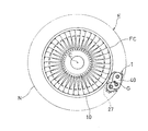
- FIG. 3 is a front view showing a state in which the aircraft power generator 1 is attached to the engine E.
- the power generator 1 is attached to the side of the fan case FC of the engine E.
- the power generation device 1 is formed in a vertically long outer shape that is thin with a small thickness when viewed from the direction of the engine axis C and has a large vertical dimension.
- the power generation device 1 can be attached to the side portion of the fan case FC of the engine E with a small protruding side.
- the engine E and the power generator 1 are covered with an engine nacelle N.
- the power generator 1 may be attached to the side surface of the engine core portion of the publication rather than the fan case FC.
- a case 40 for housing the transmission 22, the generator 34, the pump 33, and the transmission mechanism 21 of the power generation device 1 includes an opening 43 through which the transmission mechanism input shaft 27 passes, A mounting flange 44 that surrounds the periphery of the opening, and a first cover wall 45 that has a through hole 45 a that allows the input shaft 27 to pass through at the center and closes the opening 43.
- a first seal member 46 that seals between the first cover wall 45 and the input shaft 27 is disposed in the through hole 45a.
- the first cover wall 45 is for preventing foreign matter from entering when the power generating apparatus 1 is stored or transferred, and may be omitted.
- the fan case FC of the aircraft engine E includes an opening 48 that penetrates the first connecting shaft 11 together with the AGB 19, and the mounting pad 12 that surrounds the periphery of the opening 48. Is provided.
- the case 40 of the power generator 1 is attached to the fan case FC of the engine E with a structure as shown in FIG. That is, in a state where the mounting flange 44 is overlapped on the mounting pad 12 surrounding the opening 48, they are fixed to each other by the clamp band 50 having a V-shaped cross section, whereby the power generator 1 is mounted to the engine E.
- An inner peripheral spline 11 a is formed on the inner peripheral surface of the distal end hole of the first connecting shaft 11, and an outer peripheral spline 27 a that fits the inner peripheral spline 11 a is formed on the outer peripheral surface of the distal end portion of the transmission mechanism input shaft 27. .
- the transmission mechanism input shaft 27 is connected to the first connecting shaft 11 so as to be integrally rotatable and detachable in the axial direction.
- the opening 48 is closed by a second cover wall 47 having a through hole 47a of the first connecting shaft 11 at the center, and the second cover wall 47 and the first connecting shaft 11 are formed in the through hole 47a.
- a second seal member 49 that seals the gap is disposed.
- the power generation device 1 includes a transmission mechanism input shaft 27 coupled to the first coupling shaft 11 that is gear-coupled to the low pressure shaft 9 of the engine E by spline engagement as illustrated in FIG. 6, and this transmission.
- a continuously variable traction transmission 22 connected to the mechanism input shaft 27 via the transmission mechanism 21; a generator 34 disposed below the traction transmission 22 and driven by the output of the traction transmission 22;
- An oil pump 33 for lubricating oil that is disposed between the transmission 22 and the generator 34 and is driven by the output of the traction transmission 22 is provided.
- the transmission mechanism 21, the traction transmission 22, the generator 34, and the oil pump 33 have their axes C22, C34, and C33 parallel to each other and the longitudinal direction FR of the engine E, that is, the direction of the engine axis C. It is along.
- the shaft center C22 of the transmission 22 driven via the transmission mechanism 21 may have a shaft center in a direction slightly inclined from the direction orthogonal to the input shaft 27. That is, the transmission mechanism 21 is included in the present invention as long as it drives the transmission 22 around the axis C22 in the direction intersecting the input shaft 27.
- the length in the axial direction becomes longer in the order of the oil pump 33, the generator 34, and the transmission 22, and the oil pump 33 is directly overlapped with the transmission 22 in the entire axial direction, and more than half of the oil pump 33 and the generator 34 are overlapping.
- the generator 34 is overlapped with the transmission 22 in the whole axial position.
- the transmission 22 and the generator 34 may be slightly displaced in the axial direction so that more than half of them overlap.
- the traction transmission 22, the generator 34, and the oil pump 33 are housed in a case 40 that is divided in the axial direction and joined by a case flange 40a.
- the traction transmission 22 has a transmission output shaft 29 that passes through the inside of the hollow transmission input shaft 28 and is arranged concentrically with the transmission input shaft 28.
- This is a double-cavity half-toroidal traction drive type in which first and second cavities 51 and 52 are disposed along the output shaft 29 at a predetermined interval.
- First and second input disks 51a and 52a are disposed inside the cavities 51 and 52 in the axial direction, and first and second output disks 51b and 52b are disposed outside the cavities 51 and 52, respectively. Yes.
- Both input disks 51a and 52a are connected to the transmission input shaft 28 so as to rotate together, and both output disks 51b and 52b are connected to rotate together with the transmission output shaft 29.
- an intermediate portion in the direction of the axis C22 forms an input portion IN having the input gear 24, the transmission input shaft 28, and both input disks 51a and 52a, and the direction in the direction of the axis C22.
- An output portion OT having a transmission output shaft 29 and both output disks 51b and 52b is formed outside.
- a constant speed drive device is configured only by the traction transmission 22 without adopting a power split system (Patent Document 1) having a power diversion shaft.
- a first power roller 51c is provided in the first cavity 51, a second power roller 52c is provided in the second cavity 52, and a power is provided at a position close to the outside in the axial direction of the second output disk 52b.
- An axial force generation mechanism 53 for generating a pressing force that presses the rollers 51c and 52c in the axial direction is disposed.
- the power rollers 51c and 52c are supported so as to be rotatable in a plane including the roller shaft centers 51d and 52d and the transmission input shaft 28 while allowing rotation about the roller shaft centers 51d and 52d.
- the three rolling elements of the input disks 51a and 52a, the output disks 51b and 52b, and the power rollers 51c and 52c are pressed against each other by the pressing force of the axial force generating mechanism 53, Power is transmitted by the shear resistance of the high-viscosity lubricating oil film generated in That is, the driving force between the first input disk 51a and the first output disk 51b is transmitted by fluid friction with the first power roller 51c disposed between the first input disk 51a and the second input disk 52a. The driving force is transmitted to and from the second output disk 52b by fluid friction with the second power roller 52c disposed therebetween.
- a pair of power rollers 51c and 52c are also arranged at positions facing each other by 180 ° around the transmission shaft center C22.
- the acceleration ratio and the reduction ratio that is, the gear ratio is changed by controlling the tilt angle, which is the inclination of the roller shaft centers 51d and 52d of the power rollers 51c and 52c, by a control mechanism (not shown).
- the gear ratio is arbitrarily changed within a predetermined range, for example, within a range of 0.5 to 2.0. In this case, when expressed in terms of the reduction ratio, it is within 4: 1, but it may be within 5: 1 or may be in other ranges.
- An oil pump 33 that rotates integrally with the intermediate gear 32 is disposed between the traction transmission 22 and the generator 34. Therefore, the generator 34 is driven by the rotation of the transmission output shaft 29 being transmitted through the transmission output gear 30, the intermediate gear 32, and the generator input gear 39. At this time, the oil pump 33 is driven using the rotation of the intermediate gear 32.
- Bearings 54 ⁇ / b> A, 54 ⁇ / b> B, and 54 ⁇ / b> C that rotatably support the transmission output shaft 29, the pump drive shaft 31, and the generator rotating shaft 38 are attached to the support wall 58 provided in the case 40. In the power generation device 1, the rotation of the traction transmission 22 is increased by setting the gear ratio between the transmission output gear 30 and the generator input gear 39.
- the generator 34 is rotationally driven by the engine E via the traction transmission 22 and functions as a generator to supply electric power to various electric loads such as aircraft lighting, air conditioning and anti-icing devices. . Note that the positions of the traction transmission 22 and the generator 34 may be interchanged.
- the rotational speed of the transmission output shaft 29 of the traction transmission 22 has a predetermined relationship between the tilt angles of the roller shaft centers 51d and 52d of the traction transmission 22 according to the change in the rotational speed of the transmission input shaft 28.
- the rotational speed of the transmission output shaft 29 is kept constant.
- the constant rotation speed of the transmission output shaft 29 is increased by the intermediate gear 32 and then transmitted to the generator 34. Therefore, the generator 34 always rotates at a constant rotation speed at a constant frequency. Output AC power.
- the rotation of the low pressure shaft 9 of the engine E shown in FIG. 1 is transmitted to the power generator 1 via the first connecting shaft 11 and the transmission mechanism input shaft 27 shown in FIG.
- power is transmitted from the transmission mechanism input shaft 27 to the generator 34 via the transmission mechanism 21, the traction transmission 22 and the intermediate gear 32, and power is generated by the rotation of the generator 34.
- the aircraft power generation apparatus 1 of the present embodiment is housed in a case 40 in which all the components such as the transmission mechanism 21, the traction transmission 22, the generator 34, and the oil pump 33 are divided into two.
- the thin and vertically long outer shape is compactly collected.
- the downsizing of the transmission 22, the generator 34, and the oil pump 33 in the front-rear direction FR is achieved, that is, the shaft of the transmission 22 in FIG.
- the center C22, the shaft center C34 of the generator 34 and the shaft center C33 of the oil pump 33 are arranged in parallel to each other and also in parallel to the engine shaft center C.
- the transmission 22, the generator 34 and the oil pump 33 are arranged. Is arranged at intervals in the circumferential direction of the engine E of FIG.
- the traction transmission 22, the generator 34 and the oil pump 33 are parallel to the engine axis C of FIG. 1 and substantially concentric with the engine axis C when viewed from the axial direction of the traction transmission 22. This is because they are arranged on an arcuate arrangement line. Therefore, the power generator 1 has a slim shape that is vertically long and thin as a whole, that is, a shape that can be suitably attached with a small amount of protrusion from the side of the aircraft engine E, and the shape of the nacelle N that covers the engine E is Therefore, it is possible to obtain a suitable shape that can suppress an increase in the front area, and it is possible to prevent an increase in air resistance of the aircraft and prevent a decrease in fuel consumption.
- the transmission shaft center C22, the generator shaft center C34 and the pump shaft center C33 in FIG. 7 are slightly inclined in the circumferential direction around the engine shaft center C (FIG. 3) with respect to the engine shaft center C, that is, the front-rear direction FR. May be.
- the axial length of the power generator 1 can be shortened.
- the shaft center C22 of the transmission 22 and the shaft center C34 of the generator 34 are parallel to each other, the transmission 22 and the generator 34 can be connected by a simple spur gear, so the structure of the power generator 1 is simplified. .
- a transmission mechanism input shaft 27 is arranged along the radial direction of the low pressure shaft 9 of the engine E, and the rotation of the input shaft 27 is converted by the transmission mechanism 21 into a direction crossing the transmission mechanism input shaft 27.
- the transmission since the transmission is transmitted to the transmission 22, it is not necessary to separately provide an AGB when mechanically connecting the generator 34 to the low-pressure shaft 9 in order to perform large-capacity power generation. Therefore, an increase in weight, an increase in cost, an increase in air resistance, and a decrease in reliability due to the addition of AGB can be suppressed.
- the transmission mechanism input shaft 27 of FIG. 8 is disposed between the track transmission 22 and the generator 34 in the circumferential direction of the low pressure shaft 9, the traction transmission having a relatively large weight.
- the transmission mechanism input shaft 27 is positioned near the center of gravity G shown in FIG. As a result, the overhang moment of the center of gravity G with respect to the attachment flange 44 that forms the attachment surface of the power generation device 1 to the aircraft engine E is reduced, and the attachment of the power generation device 1 to the aircraft engine E is stabilized.
- the transmission mechanism input shaft 27 connected to the input portion IN of the transmission 22 via the transmission mechanism 21 is disposed in the intermediate portion in the direction of the transmission shaft center C22, the transmission mechanism input shaft 27 is connected to the generator 34. It becomes easy to approach the center of gravity, and the above-mentioned overhang moment can be further reduced. Although the transmission mechanism input shaft 27 of FIG. 8 may be disposed above the tracking transmission 22, in that case, the overhang moment of the center of gravity G with respect to the mounting flange 44 becomes large.
- a case 40 that houses the tracking transmission 22 and the generator 34 of the power generation device 1 shown in FIG. 6 has an opening 43 that penetrates the transmission mechanism input shaft 27 and a mounting flange 44 that surrounds the opening 43. , And can be attached to the engine E via the attachment flange 44. Therefore, by attaching the mounting flange 44 surrounding the periphery of the opening 43 in the case 40 to the mounting pad 12 of the engine E, for example, by the clamp band 50 or the like in an overlapped state, the power generator 1 can be easily mounted by the engine E. Can be attached stably.
- the power generation device 1 of this embodiment is a constant speed drive mechanism that transmits the rotation of the engine E to the generator 34 only through the traction transmission 22 without adopting the power split method, so that the traction transmission 22 1 can be set to about 5: 1, so that the generator 34 can be rotated at a constant speed even when connected to the low pressure shaft 9 of FIG. Is possible.
- the power generation capacity can be increased by using the large disks 51a, 51b, 52a, 52b in the traction transmission 22 of FIG. In that case, the rotation of the traction transmission 22 is increased via the intermediate gear 32 and the generator 34 is rotated at a high speed, so that the torque of the transmission 22 is reduced, resulting in excessive increase in size and weight. Can be suppressed.
- the rotation of the traction transmission 22 is transmitted to the generator 34 after being accelerated through the intermediate gear 32.
- Both the transmission 22 and the generator 34 can be driven at an appropriate rotation speed, and the rotation of the traction transmission 22 is increased to a rotation speed that drives the generator 34 at a stretch and transmitted. Loss generation can be prevented.
- the oil pump 33 is driven by using the rotation of the intermediate gear 32 for speed increase, a dedicated drive system for driving the pump is not required. It can supply to the lubrication object part of the transmission 22 and the generator 34.
- FIG. 9 is a configuration diagram schematically showing a connection state of the aircraft power generation apparatus 1A according to the second embodiment of the present invention to the engine E, and the same reference numerals are given to the same or corresponding parts as those in FIG. Therefore, a duplicate description is omitted.
- the power generator 1A of this embodiment is different from the power generator 1 of FIG. 1 in that the transmission shaft 17 is omitted and a bevel gear 59A of the transmission mechanism 21A is provided on the transmission input shaft 28 of the traction transmission 22. This is only the point where the gear 59B is directly meshed with the gear 59B.
- this transmission mechanism 21A as with the transmission mechanism 21 of FIG. 2, the rotation of the transmission mechanism input shaft 27 is converted into the rotation around the axis in the direction orthogonal to the transmission mechanism input shaft 27 and transmitted to the traction transmission 22. can do.
- the transmission 22 is not limited to a traction continuously variable transmission, and may be a belt drive type continuously variable transmission or other continuously variable transmission.
Abstract
Description
図1は、本発明の第1実施形態に係る航空機用発電装置1のエンジンEへの連結状態を模式的に示した構成図である。エンジンEは、2軸型ファンエンジンであり、圧縮機2、燃焼器3、タービン4およびファン10を主要構成要素として備えている。圧縮機2から供給される圧縮空気に燃料を混合して燃焼器3で燃焼させ、その燃焼により発生する高温高圧の燃焼ガスがタービン4に供給される。 Hereinafter, preferred embodiments of the present invention will be described with reference to the drawings.
FIG. 1 is a configuration diagram schematically showing a connection state of an aircraft
2 圧縮機
7 高圧軸
9 低圧軸(回転軸)
10 ファン
21,21A 伝動機構
22 トラックション変速機(変速機)
27 伝動機構入力軸(入力軸)
31 ポンプ回転軸(ギヤ軸)
32 中間ギヤ
33 オイルポンプ(ポンプ)
34 発電機
40 ケース
43 開口
44 取付フランジ
E 航空機用エンジン
FC ファンケース
IN 変速機入力部
OT 変速機出力部
R 径方向 1,
10
27 Transmission mechanism input shaft (input shaft)
31 Pump rotation shaft (gear shaft)
32
34
Claims (11)
- 航空機用エンジンにより駆動される発電装置であって、
前記エンジンの回転軸に連結される変速機と、
前記変速機の出力により駆動される発電機と、
前記回転軸と交差する方向に沿った軸心を有し、前記回転軸に連結される入力軸と、
前記入力軸に連結されて前記入力軸と交差する方向の軸心回りに前記変速機を駆動する伝動機構とを備え、
前記変速機と前記発電機が前記回転軸の周方向に離間して配置されている航空機用発電装置。 A power generator driven by an aircraft engine,
A transmission coupled to the rotating shaft of the engine;
A generator driven by the output of the transmission;
An input shaft having an axial center along a direction intersecting with the rotation axis and coupled to the rotation axis;
A transmission mechanism connected to the input shaft and driving the transmission about an axis in a direction intersecting the input shaft;
An aircraft power generator in which the transmission and the generator are spaced apart from each other in the circumferential direction of the rotating shaft. - 請求項1において、前記入力軸が前記周方向における前記変速機と前記発電機の間に配置されている航空機用発電装置。 2. The aircraft power generator according to claim 1, wherein the input shaft is disposed between the transmission and the generator in the circumferential direction.
- 請求項1または2において、前記変速機と前記発電機は互いに平行な軸心を有し、少なくとも一部分の軸心方向位置が互いに重なっている航空機用発電装置。 3. The aircraft power generator according to claim 1 or 2, wherein the transmission and the generator have axes parallel to each other, and at least a part of the axial direction positions overlap each other.
- 請求項1,2または3において、ファンを駆動する低圧軸と圧縮機を駆動する高圧軸とを備える前記エンジンにより駆動され、
前記回転軸が前記低圧軸である航空機用発電装置。 Driven by the engine according to claim 1, 2 or 3, comprising a low pressure shaft for driving a fan and a high pressure shaft for driving a compressor,
An aircraft power generator in which the rotating shaft is the low-pressure shaft. - 請求項1から4のいずれか一項において、前記変速機がトラクション無段変速機である航空機用発電装置。 The aircraft power generation device according to any one of claims 1 to 4, wherein the transmission is a traction continuously variable transmission.
- 請求項5において、前記トランクション無段変速機はダブルキャビティ型であり、その軸心方向における中間部に入力部が設けられ、その外側に出力部が設けられている航空機用発電装置。 6. The aircraft power generation device according to claim 5, wherein the trunkless continuously variable transmission is of a double cavity type, an input portion is provided at an intermediate portion in an axial direction thereof, and an output portion is provided outside thereof.
- 請求項1から6のいずれか一項において、前記変速機および前記発電機を収納するケースが、前記入力軸を貫通させる開口と、この開口の周囲を取り囲むフランジとを有し、前記フランジを介して前記ケースが前記エンジンに取り付けられている航空機用発電装置。 7. The case of housing the transmission and the generator according to claim 1, further comprising: an opening that allows the input shaft to pass through; and a flange that surrounds the periphery of the input shaft. An aircraft power generator in which the case is attached to the engine.
- 請求項1から7のいずれか一項において、さらに、前記変速機と前記発電機との間をギヤ連結する中間ギヤを有する航空機用発電装置。 The aircraft power generator according to any one of claims 1 to 7, further comprising an intermediate gear that gear-couples between the transmission and the generator.
- 請求項8において、さらに、前記中間ギヤのギヤ軸に連結されて潤滑油を供給するポンプを備えた航空機用発電装置。 9. The aircraft power generator according to claim 8, further comprising a pump that is connected to a gear shaft of the intermediate gear and supplies lubricating oil.
- 請求項1から9のいずれか一項において、前記変速機と前記発電機の軸心が前記回転軸と平行である航空機用発電装置。 The aircraft power generator according to any one of claims 1 to 9, wherein an axis of the transmission and the generator is parallel to the rotating shaft.
- 請求項1から10のいずれか一項において、前記入力軸は、前記エンジンの回転軸の径方向に沿った軸心を有する航空機用発電装置。
11. The aircraft power generator according to claim 1, wherein the input shaft has an axial center along a radial direction of a rotation shaft of the engine.
Priority Applications (5)
| Application Number | Priority Date | Filing Date | Title |
|---|---|---|---|
| JP2013508911A JP5703370B2 (en) | 2011-04-07 | 2012-04-04 | Aircraft power generator |
| CN201280016072.4A CN103459807B (en) | 2011-04-07 | 2012-04-04 | Airborne vehicle TRT |
| CA2832153A CA2832153C (en) | 2011-04-07 | 2012-04-04 | Generating device for aircraft |
| EP12767296.2A EP2696058B1 (en) | 2011-04-07 | 2012-04-04 | Aircraft with a generator apparatus |
| US14/110,050 US9890839B2 (en) | 2011-04-07 | 2012-04-04 | Generating device for aircraft |
Applications Claiming Priority (2)
| Application Number | Priority Date | Filing Date | Title |
|---|---|---|---|
| JP2011-085428 | 2011-04-07 | ||
| JP2011085428 | 2011-04-07 |
Publications (1)
| Publication Number | Publication Date |
|---|---|
| WO2012137843A1 true WO2012137843A1 (en) | 2012-10-11 |
Family
ID=46969237
Family Applications (2)
| Application Number | Title | Priority Date | Filing Date |
|---|---|---|---|
| PCT/JP2012/059246 WO2012137843A1 (en) | 2011-04-07 | 2012-04-04 | Generator apparatus for aircraft |
| PCT/JP2012/059247 WO2012137844A1 (en) | 2011-04-07 | 2012-04-04 | Aircraft engine |
Family Applications After (1)
| Application Number | Title | Priority Date | Filing Date |
|---|---|---|---|
| PCT/JP2012/059247 WO2012137844A1 (en) | 2011-04-07 | 2012-04-04 | Aircraft engine |
Country Status (6)
| Country | Link |
|---|---|
| US (2) | US9890839B2 (en) |
| EP (2) | EP2696057B1 (en) |
| JP (2) | JP5703370B2 (en) |
| CN (2) | CN103459807B (en) |
| CA (2) | CA2832155C (en) |
| WO (2) | WO2012137843A1 (en) |
Cited By (7)
| Publication number | Priority date | Publication date | Assignee | Title |
|---|---|---|---|---|
| WO2016143331A1 (en) * | 2015-03-09 | 2016-09-15 | 川崎重工業株式会社 | Power generating device for aircraft |
| JP2016169828A (en) * | 2015-03-13 | 2016-09-23 | 川崎重工業株式会社 | Speed change gear and power generating system with speed change gear |
| JP2016537545A (en) * | 2013-10-11 | 2016-12-01 | イスパノ・シユイザ | Auxiliary gearbox for turbomachinery |
| US10605165B2 (en) | 2014-12-24 | 2020-03-31 | Kawasaki Jukogyo Kabushiki Kaisha | Aircraft engine apparatus |
| WO2022091275A1 (en) | 2020-10-28 | 2022-05-05 | 川崎重工業株式会社 | Aircraft gas turbine engine |
| US11362566B2 (en) | 2015-03-09 | 2022-06-14 | Kawasaki Jukogyo Kabushiki Kaisha | Toroidal continuously variable transmission and integrated drive generator |
| US11566566B2 (en) | 2014-12-24 | 2023-01-31 | Kawasaki Jukogyo Kabushiki Kaisha | Aircraft engine power generator disposed inside of a stationary nose cone |
Families Citing this family (17)
| Publication number | Priority date | Publication date | Assignee | Title |
|---|---|---|---|---|
| US9297314B2 (en) * | 2012-12-19 | 2016-03-29 | United Technologies Corporation | Gas turbine engine with accessory gear box |
| FR3005491B1 (en) * | 2013-05-10 | 2015-06-05 | Hispano Suiza Sa | INTEGRATION OF PUMPS TO A GEARBOX APPENDIX TO AN AIRCRAFT ENGINE |
| FR3006997B1 (en) * | 2013-06-14 | 2016-12-23 | Airbus | AIRCRAFT WITH ELECTRICAL PROPULSION MEANS |
| WO2015047577A1 (en) * | 2013-09-26 | 2015-04-02 | United Technologies Corporation | Gas turbine engine with split lubrication system |
| FR3016408B1 (en) * | 2014-01-16 | 2019-05-31 | Safran Transmission Systems | ACCESSORY TRAINING ASSEMBLY FOR AIRCRAFT TURBINE ENGINE |
| FR3017658B1 (en) * | 2014-02-18 | 2019-04-12 | Safran Transmission Systems | EQUIPMENT DRIVE HOUSING FOR TURBOMACHINE |
| US10500464B2 (en) * | 2014-03-20 | 2019-12-10 | Shooter's Touch, Llc | Basketball performance monitoring system |
| FR3041052B1 (en) * | 2015-09-14 | 2018-07-27 | Safran Transmission Systems | BOX FOR DRIVING EQUIPMENT IN A TURBOMACHINE |
| GB201610234D0 (en) * | 2016-06-13 | 2016-07-27 | Rolls Royce Plc | An accessory gearbox assembly and a gas turbine engine comprising an accessory gearbox assembly |
| CN106763769A (en) * | 2016-11-15 | 2017-05-31 | 中国舰船研究设计中心 | A kind of close property device in mechanical connection face |
| US10533499B2 (en) * | 2017-10-03 | 2020-01-14 | Hamilton Sundstrand Corporation | Seal plate located between two housing portions in an integrated drive generator |
| US11346427B2 (en) | 2019-02-13 | 2022-05-31 | Raytheon Technologies Corporation | Accessory gearbox for gas turbine engine with variable transmission |
| US20200284326A1 (en) * | 2019-03-05 | 2020-09-10 | Hamilton Sundstrand Corporation | Continuously variable transmission for ram air turbines |
| JP7316135B2 (en) * | 2019-07-22 | 2023-07-27 | 川崎重工業株式会社 | Toroidal continuously variable transmission and power generator with integrated drive mechanism for aircraft |
| FR3099209B1 (en) * | 2019-07-26 | 2021-06-25 | Safran Aircraft Engines | DEVICE FOR DRIVING A GENERATOR OF AN AIRCRAFT TURBOMACHINE AND PROCESS FOR REGULATING THE SPEED OF SUCH A GENERATOR |
| JP2021127731A (en) * | 2020-02-14 | 2021-09-02 | 川崎重工業株式会社 | Gas-turbine engine |
| FR3117530B1 (en) * | 2020-12-15 | 2024-01-05 | Safran Aircraft Engines | Aircraft turbomachine assembly including an equipment support |
Citations (3)
| Publication number | Priority date | Publication date | Assignee | Title |
|---|---|---|---|---|
| JPS5527582A (en) * | 1978-08-11 | 1980-02-27 | Sundstrand Corp | Driving device builttin type generator |
| JP3440287B2 (en) | 1999-12-01 | 2003-08-25 | 川崎重工業株式会社 | Constant speed driving method and constant speed driving apparatus for aircraft generator |
| JP2010179815A (en) | 2009-02-06 | 2010-08-19 | Kawasaki Heavy Ind Ltd | Power-generating device for aircraft |
Family Cites Families (21)
| Publication number | Priority date | Publication date | Assignee | Title |
|---|---|---|---|---|
| US2978869A (en) * | 1956-11-01 | 1961-04-11 | Bristol Siddeley Engines Ltd | Engine accessory mounting arrangements |
| US3688560A (en) | 1971-01-29 | 1972-09-05 | Gen Electric | Gas turbine engine with improved auxiliary power take-off |
| FR2152362B1 (en) * | 1971-09-07 | 1974-05-10 | Snecma | |
| US3834161A (en) | 1973-06-01 | 1974-09-10 | Us Air Force | Dual mode auxiliary power unit |
| US4712370A (en) * | 1986-04-24 | 1987-12-15 | The United States Of America As Represented By The Secretary Of The Air Force | Sliding duct seal |
| US5470114A (en) | 1994-11-14 | 1995-11-28 | General Electric Company | Coupling assembly |
| FR2767374B1 (en) * | 1997-08-13 | 1999-09-17 | Hispano Suiza Sa | SEALING ARRANGEMENT FOR A TREE END |
| JP2001317374A (en) * | 2000-04-28 | 2001-11-16 | Honda Motor Co Ltd | Auxiliary machine driving unit for gas turbine engine |
| US7975465B2 (en) | 2003-10-27 | 2011-07-12 | United Technologies Corporation | Hybrid engine accessory power system |
| US7386983B2 (en) | 2004-02-25 | 2008-06-17 | United Technologies Corporation | Apparatus for driving an accessory gearbox in a gas turbine engine |
| US7500365B2 (en) * | 2005-05-05 | 2009-03-10 | United Technologies Corporation | Accessory gearbox |
| US7805947B2 (en) | 2005-05-19 | 2010-10-05 | Djamal Moulebhar | Aircraft with disengageable engine and auxiliary power unit components |
| FR2892456B1 (en) | 2005-10-21 | 2008-01-04 | Hispano Suiza Sa | DEVICE FOR DRIVING ACCESSORY MACHINES OF A GAS TURBINE ENGINE |
| FR2894621B1 (en) * | 2005-12-09 | 2011-10-14 | Hispano Suiza Sa | AUXILIARY MACHINE DRIVE SYSTEM OF A DUAL BODY TURBOMOTEUR |
| DE102006015639A1 (en) * | 2006-04-04 | 2007-10-11 | Mtu Aero Engines Gmbh | Jet engine with generator unit |
| JP4906455B2 (en) | 2006-09-26 | 2012-03-28 | 本田技研工業株式会社 | Crankcase structure of internal combustion engine |
| FR2911917B1 (en) | 2007-01-31 | 2013-05-17 | Hispano Suiza Sa | DISTRIBUTED GAS TURBINE GENERATOR-STARTER ARCHITECTURE |
| US8015828B2 (en) | 2007-04-03 | 2011-09-13 | General Electric Company | Power take-off system and gas turbine engine assembly including same |
| US20090188334A1 (en) * | 2008-01-25 | 2009-07-30 | United Technologies Corp. | Accessory Gearboxes and Related Gas Turbine Engine Systems |
| US8172512B2 (en) * | 2008-04-23 | 2012-05-08 | Hamilton Sundstrand Corporation | Accessory gearbox system with compressor driven seal air supply |
| FR2941744B1 (en) | 2009-01-30 | 2011-09-16 | Hispano Suiza Sa | ASSEMBLY OF AN ACCESSORY RELAY HOUSING AND AN OIL TANK |
-
2012
- 2012-04-04 JP JP2013508911A patent/JP5703370B2/en active Active
- 2012-04-04 CA CA2832155A patent/CA2832155C/en active Active
- 2012-04-04 EP EP12767294.7A patent/EP2696057B1/en active Active
- 2012-04-04 CN CN201280016072.4A patent/CN103459807B/en not_active Expired - Fee Related
- 2012-04-04 US US14/110,050 patent/US9890839B2/en active Active
- 2012-04-04 US US14/110,016 patent/US9765861B2/en active Active
- 2012-04-04 EP EP12767296.2A patent/EP2696058B1/en active Active
- 2012-04-04 WO PCT/JP2012/059246 patent/WO2012137843A1/en active Application Filing
- 2012-04-04 CN CN201280015823.0A patent/CN103459806B/en not_active Expired - Fee Related
- 2012-04-04 CA CA2832153A patent/CA2832153C/en active Active
- 2012-04-04 WO PCT/JP2012/059247 patent/WO2012137844A1/en active Application Filing
- 2012-04-04 JP JP2013508912A patent/JP5583847B2/en active Active
Patent Citations (3)
| Publication number | Priority date | Publication date | Assignee | Title |
|---|---|---|---|---|
| JPS5527582A (en) * | 1978-08-11 | 1980-02-27 | Sundstrand Corp | Driving device builttin type generator |
| JP3440287B2 (en) | 1999-12-01 | 2003-08-25 | 川崎重工業株式会社 | Constant speed driving method and constant speed driving apparatus for aircraft generator |
| JP2010179815A (en) | 2009-02-06 | 2010-08-19 | Kawasaki Heavy Ind Ltd | Power-generating device for aircraft |
Non-Patent Citations (1)
| Title |
|---|
| See also references of EP2696058A4 |
Cited By (9)
| Publication number | Priority date | Publication date | Assignee | Title |
|---|---|---|---|---|
| JP2016537545A (en) * | 2013-10-11 | 2016-12-01 | イスパノ・シユイザ | Auxiliary gearbox for turbomachinery |
| US10605165B2 (en) | 2014-12-24 | 2020-03-31 | Kawasaki Jukogyo Kabushiki Kaisha | Aircraft engine apparatus |
| US11566566B2 (en) | 2014-12-24 | 2023-01-31 | Kawasaki Jukogyo Kabushiki Kaisha | Aircraft engine power generator disposed inside of a stationary nose cone |
| WO2016143331A1 (en) * | 2015-03-09 | 2016-09-15 | 川崎重工業株式会社 | Power generating device for aircraft |
| JP2016165950A (en) * | 2015-03-09 | 2016-09-15 | 川崎重工業株式会社 | Power generation device for aircraft |
| US10822106B2 (en) | 2015-03-09 | 2020-11-03 | Kawasaki Jukogyo Kabushiki Kaisha | Electric power generating device for aircraft |
| US11362566B2 (en) | 2015-03-09 | 2022-06-14 | Kawasaki Jukogyo Kabushiki Kaisha | Toroidal continuously variable transmission and integrated drive generator |
| JP2016169828A (en) * | 2015-03-13 | 2016-09-23 | 川崎重工業株式会社 | Speed change gear and power generating system with speed change gear |
| WO2022091275A1 (en) | 2020-10-28 | 2022-05-05 | 川崎重工業株式会社 | Aircraft gas turbine engine |
Also Published As
| Publication number | Publication date |
|---|---|
| WO2012137844A1 (en) | 2012-10-11 |
| EP2696058A4 (en) | 2015-04-22 |
| US20140038770A1 (en) | 2014-02-06 |
| EP2696058B1 (en) | 2017-10-11 |
| CN103459807A (en) | 2013-12-18 |
| CN103459807B (en) | 2016-08-17 |
| US9890839B2 (en) | 2018-02-13 |
| CA2832153A1 (en) | 2012-10-11 |
| JPWO2012137843A1 (en) | 2014-07-28 |
| EP2696057A1 (en) | 2014-02-12 |
| US20140026589A1 (en) | 2014-01-30 |
| CA2832155C (en) | 2015-02-24 |
| JP5703370B2 (en) | 2015-04-15 |
| JP5583847B2 (en) | 2014-09-03 |
| EP2696058A1 (en) | 2014-02-12 |
| JPWO2012137844A1 (en) | 2014-07-28 |
| CN103459806A (en) | 2013-12-18 |
| EP2696057A4 (en) | 2015-04-22 |
| US9765861B2 (en) | 2017-09-19 |
| CN103459806B (en) | 2016-01-20 |
| CA2832153C (en) | 2015-02-10 |
| CA2832155A1 (en) | 2012-10-11 |
| EP2696057B1 (en) | 2017-10-18 |
Similar Documents
| Publication | Publication Date | Title |
|---|---|---|
| JP5703370B2 (en) | Aircraft power generator | |
| JP4700113B2 (en) | Aircraft generator | |
| US10151249B2 (en) | Gas turbine architecture | |
| EP2530282B1 (en) | Dual drive of an accessory drive gearbox | |
| US10273883B2 (en) | Engine accessory drives systems and methods | |
| JP5620519B2 (en) | Counter-rotating propeller system for aircraft turbine engines | |
| US20110101693A1 (en) | Aircraft starter generator | |
| US10145260B2 (en) | Accessory drive case for a turboprop | |
| US20140124618A1 (en) | Counter rotating facegear gearbox | |
| US11067006B2 (en) | Gas turbine engine system with synchronization features for gearbox operation | |
| US4118997A (en) | Bevel gearing | |
| US9951695B2 (en) | Multi-axis accessory gearboxes of mechanical drive systems and gas turbine engines including the same | |
| JP6343243B2 (en) | Aircraft power generator | |
| US20160333793A1 (en) | Accessory gearbox assembly for an aircraft turbine engine | |
| US20220268215A1 (en) | Epicyclic reduction gear for a turbomachine | |
| US11326523B2 (en) | Gas turbine engine with accessory gearbox | |
| US20240003302A1 (en) | Compressed air supply system | |
| US11802514B2 (en) | Epicyclic reduction gear for a turbomachine | |
| US20130260940A1 (en) | Gearing Assembly |
Legal Events
| Date | Code | Title | Description |
|---|---|---|---|
| 121 | Ep: the epo has been informed by wipo that ep was designated in this application |
Ref document number: 12767296 Country of ref document: EP Kind code of ref document: A1 |
|
| ENP | Entry into the national phase |
Ref document number: 2013508911 Country of ref document: JP Kind code of ref document: A |
|
| ENP | Entry into the national phase |
Ref document number: 2832153 Country of ref document: CA |
|
| WWE | Wipo information: entry into national phase |
Ref document number: 14110050 Country of ref document: US |
|
| NENP | Non-entry into the national phase |
Ref country code: DE |
|
| REEP | Request for entry into the european phase |
Ref document number: 2012767296 Country of ref document: EP |
|
| WWE | Wipo information: entry into national phase |
Ref document number: 2012767296 Country of ref document: EP |