WO2012137246A1 - 災害救助用のジャッキ - Google Patents
災害救助用のジャッキ Download PDFInfo
- Publication number
- WO2012137246A1 WO2012137246A1 PCT/JP2011/002008 JP2011002008W WO2012137246A1 WO 2012137246 A1 WO2012137246 A1 WO 2012137246A1 JP 2011002008 W JP2011002008 W JP 2011002008W WO 2012137246 A1 WO2012137246 A1 WO 2012137246A1
- Authority
- WO
- WIPO (PCT)
- Prior art keywords
- jack
- hydrogen gas
- base
- jack portion
- disaster
- Prior art date
- Legal status (The legal status is an assumption and is not a legal conclusion. Google has not performed a legal analysis and makes no representation as to the accuracy of the status listed.)
- Ceased
Links
Images


Classifications
-
- B—PERFORMING OPERATIONS; TRANSPORTING
- B66—HOISTING; LIFTING; HAULING
- B66F—HOISTING, LIFTING, HAULING OR PUSHING, NOT OTHERWISE PROVIDED FOR, e.g. DEVICES WHICH APPLY A LIFTING OR PUSHING FORCE DIRECTLY TO THE SURFACE OF A LOAD
- B66F3/00—Devices, e.g. jacks, adapted for uninterrupted lifting of loads
- B66F3/24—Devices, e.g. jacks, adapted for uninterrupted lifting of loads fluid-pressure operated
- B66F3/25—Constructional features
-
- B—PERFORMING OPERATIONS; TRANSPORTING
- B66—HOISTING; LIFTING; HAULING
- B66F—HOISTING, LIFTING, HAULING OR PUSHING, NOT OTHERWISE PROVIDED FOR, e.g. DEVICES WHICH APPLY A LIFTING OR PUSHING FORCE DIRECTLY TO THE SURFACE OF A LOAD
- B66F3/00—Devices, e.g. jacks, adapted for uninterrupted lifting of loads
- B66F3/24—Devices, e.g. jacks, adapted for uninterrupted lifting of loads fluid-pressure operated
- B66F3/247—Devices, e.g. jacks, adapted for uninterrupted lifting of loads fluid-pressure operated pneumatically actuated
-
- B—PERFORMING OPERATIONS; TRANSPORTING
- B66—HOISTING; LIFTING; HAULING
- B66F—HOISTING, LIFTING, HAULING OR PUSHING, NOT OTHERWISE PROVIDED FOR, e.g. DEVICES WHICH APPLY A LIFTING OR PUSHING FORCE DIRECTLY TO THE SURFACE OF A LOAD
- B66F3/00—Devices, e.g. jacks, adapted for uninterrupted lifting of loads
- B66F3/24—Devices, e.g. jacks, adapted for uninterrupted lifting of loads fluid-pressure operated
- B66F3/25—Constructional features
- B66F3/26—Adaptations or arrangements of pistons
- B66F3/28—Adaptations or arrangements of pistons telescopic
-
- B—PERFORMING OPERATIONS; TRANSPORTING
- B66—HOISTING; LIFTING; HAULING
- B66F—HOISTING, LIFTING, HAULING OR PUSHING, NOT OTHERWISE PROVIDED FOR, e.g. DEVICES WHICH APPLY A LIFTING OR PUSHING FORCE DIRECTLY TO THE SURFACE OF A LOAD
- B66F3/00—Devices, e.g. jacks, adapted for uninterrupted lifting of loads
- B66F3/24—Devices, e.g. jacks, adapted for uninterrupted lifting of loads fluid-pressure operated
- B66F3/25—Constructional features
- B66F3/35—Inflatable flexible elements, e.g. bellows
-
- F—MECHANICAL ENGINEERING; LIGHTING; HEATING; WEAPONS; BLASTING
- F15—FLUID-PRESSURE ACTUATORS; HYDRAULICS OR PNEUMATICS IN GENERAL
- F15B—SYSTEMS ACTING BY MEANS OF FLUIDS IN GENERAL; FLUID-PRESSURE ACTUATORS, e.g. SERVOMOTORS; DETAILS OF FLUID-PRESSURE SYSTEMS, NOT OTHERWISE PROVIDED FOR
- F15B15/00—Fluid-actuated devices for displacing a member from one position to another; Gearing associated therewith
- F15B15/08—Characterised by the construction of the motor unit
- F15B15/14—Characterised by the construction of the motor unit of the straight-cylinder type
- F15B15/16—Characterised by the construction of the motor unit of the straight-cylinder type of the telescopic type
Definitions
- the present invention relates to a portable disaster rescue jack used to rescue a victim who is underlayed in a building collapsed due to an earthquake disaster or a typhoon disaster, or who is alive buried in a collapsed ground.
- the actuator of Patent Document 1 is known.
- hydrogen gas stored in the metal hydride is placed in the working chamber defined by the cylinder and piston, and the metal hydride is heated by a Peltier element by heating the metal hydride. Is released into the working chamber so that the piston rod can be advanced.
- the hydrogen gas is adsorbed by the metal hydride so that the piston rod can be retracted into the cylinder. ing.
- Patent Document 2 discloses an automobile jack using a hydrogen storage alloy.
- a jack is constituted by a hydrogen storage alloy containing a hydrogen storage alloy and a filter and a hydrogen container in a sealed container and a fluid pressure cylinder.
- the hydrogen inlet / outlet and the working chamber of the fluid pressure cylinder are connected by a pressure hose.
- the hydrogen inlet / outlet is brought into close contact with the outer surface of an automobile muffler and heated to release the hydrogen gas stored in the hydrogen storage alloy.
- the hydraulic cylinder can be operated and jacked up. Further, by removing the hydrogen inlet / outlet from the muffler of the automobile, the hydrogen storage alloy can be cooled to store hydrogen gas, and the piston rod of the fluid pressure cylinder can be retracted into the cylinder.
- Patent Document 3 also discloses a jack that operates by utilizing the heat of exhaust gas from an automobile.
- a working chamber is defined by a base cylinder and a lifting cylinder that moves up and down relative to the base cylinder, and a hydrogen storage alloy and a filter are arranged inside the working chamber.
- the circumference of the base cylinder is surrounded by a gas jacket.
- JP 61-270505 A page 2, lower left column, lines 1 to 18, line 1
- Japanese Patent Laid-Open No. 02-095697 (2nd page, lower left column, lines 5 to 20, line 1)
- Japanese Unexamined Patent Publication No. 04-356259 paragraph number 0007, FIG. 1
- the actuator of Patent Document 1 needs to supply a direct current to drive the Peltier element, and cannot be used in an earthquake disaster or a typhoon disaster where power supply is interrupted.
- the jacks of Patent Documents 2 and 3 heat the hydrogen storage alloy using the exhaust gas of the automobile as a heat source, they cannot be used when engine fuel is not available.
- the jack cannot be operated in a narrow disaster site where a car cannot enter.
- a hydraulic cylinder structure jack having a piston and a cylinder as constituent elements cannot be installed without an installation space corresponding to at least the entire length of the cylinder. This is because in the situation where the victims under the collapsed building are rescued, the gap under the rubble to be lifted is often small, making it difficult to install a jack between the rubble and the ground. .
- An object of the present invention is to provide a disaster rescue jack that can be used in a disaster site where it is difficult to obtain electric power or engine fuel, can be carried by foot, and can be installed in a small gap under rubble. It is to provide.
- the disaster rescue jack is supplied from a hydrogen gas supply structure 2 that heats the hydrogen storage alloy 22 with a heat source 23 and supplies hydrogen gas stored in the hydrogen storage alloy 22, and a hydrogen gas supply structure 2. And an operating structure 1 that elevates the jack-up target by being expanded by the pressure of the generated hydrogen gas.
- the operation structure 1 includes an operation base 3 placed on an installation surface, and a jack portion 5 that is assembled to the operation base 3 and includes an operation space 4 sealed inside.
- the jack portion 5 is configured to be able to expand and contract between a standby posture in which the push-up portion 10 provided at the upper end is stored in the vicinity of the operation base 3 and an extension posture in which the push-up portion 10 protrudes above the operation base. . In a state where the jack portion 5 is retracted to the standby posture, the entire operation structure 1 can be held in a flat shape (see FIG. 2).
- the jack part 5 is configured to be extendable by assembling a plurality of vertically slidable telescopic cylinders 6 to 9 into a multistage cylinder. By supplying the hydrogen gas supplied by the hydrogen gas supply structure 2 to the working space 4, the jack portion 5 can be switched from the standby posture to the extended posture.
- a bellows 33 that partitions the working space 4 is accommodated inside the jack portion 5.
- the bellows 33 is disposed between the telescopic cylinder 9 positioned at the uppermost stage and the operation base 3.
- the operating structure 1 includes a jack portion 5 constituted by one of an extendable bellows 33 and a diaphragm 34, and a push-up portion 10 fixed to the upper end of the jack portion 5. And a working base 3 fixed to the lower end of the jack portion 5.
- an expansion / contraction guide structure 15 that restricts the tilting of the jack portion 5 is provided in the working space 4 while following the expansion / contraction operation of the jack portion 5.
- the operating base 3 is formed in a dish shape that opens upward.
- the entire jack portion 5 in the retracted state to the standby posture can be stored in the operation base 3 (see FIG. 2).
- the hydrogen gas supply structure 2 is disposed inside the operation base 3 (see FIG. 1).
- the heating source of the hydrogen gas supply structure 2 is any one of the electric heat of the heater 23 using the battery 25 as a driving source, the combustion heat of the solid fuel 36, the hydrolysis reaction heat of the quicklime 37, and the combustion heat of the combustible waste in the disaster area. It consists of one.
- a disaster relief jack is constituted by the hydrogen gas supply structure 2 and the operation structure 1 that elevates the jack-up target by expanding with the pressure of the hydrogen gas.
- the operation structure 1 is configured by the operation base 3 and the jack portion 5 having the operation space 4 sealed inside, and the jack portion 5 is configured to be able to extend and contract between the standby posture and the extended posture. .
- the jack using hydrogen gas as a drive medium can be operated without problems even in disaster sites where it is difficult to obtain electric power and engine fuel or in narrow disaster sites where automobiles cannot enter.
- jacks that use hydrogen gas as the drive medium can output a much larger maximum lifting load than mechanical screw jacks or pneumatic jacks, so they are subject to heavier jackup such as rubble at the disaster site. Can be lifted reliably. Furthermore, since the entire operation structure 1 is held in a flat shape in a state in which the jack portion 5 is retracted to the standby position, the entire jack can be stored more compactly than a conventional jack having a piston and a cylinder as components. Therefore, carrying by walking can be facilitated. Furthermore, since the entire operation structure 1 is stored in a flat shape in the standby position, even if there is only a small gap under the rubble to be jacked up, the jack is securely installed and the rubble etc. is accurately raised. It is possible to provide a jack for disaster relief that can be lifted and is easy to use as a whole.
- the jack part 5 When the jack part 5 is configured to be extendable and retractable by assembling a plurality of extension cylinders 6 to 9 in a multistage cylinder shape, the jack part 5 is set in a standby posture and an extension posture by supplying hydrogen gas to the internal working space 4 thereof. Can be expanded and contracted positively. That is, the jack portion 5 can be linearly expanded and contracted in a state where the middle portion of the jack portion 5 is bent or the entire portion is largely inclined. Therefore, the jack-up target can be lifted accurately and accurately.
- the jack portion 5 can be extended by supplying hydrogen gas to the inside of the bellows 33. . Therefore, the amount of hydrogen gas to be supplied to the working space 4 can be reduced compared with the case where the entire internal space of the jack portion 5 is the working space 4, and the hydrogen stored in the hydrogen storage alloy 22 is wasted.
- the jack portion 5 can be accurately extended while being supplied in the absence.
- all of the hydrogen gas supplied to the working space 4 is held in the sealed bellows 33, even if the jack portion 5 may tilt during expansion, the hydrogen gas leaks to the outside. Thus, the reliability of the disaster rescue jack can be improved.
- the jack structure can be remarkably simplified.
- the expanding / contracting jack portion 5 is constituted by either the bellows 33 or the diaphragm 34, the jack can be remarkably reduced in weight as compared with the jack portion 5 having a telescopic structure. Therefore, although a push-up load similar to that of the jack having the telescopic jack portion 5 can be output, the overall cost can be reduced, and it is possible to provide a simple jack that is easy to carry and handle. .
- the expansion / contraction guide structure 15 can restrict the tilting of the jack portion 5 during expansion / contraction. Therefore, the jack portion 5 can be prevented from extending while being tilted due to variations in the load on the push-up portion 10, and the push-up load of the jack portion 5 can be accurately output. Further, since the telescopic guide structure 15 is expanded and contracted following the expansion and contraction operation of the jack portion 5, the entire jack can be stored compactly in a state of being in the standby position, facilitating carrying and carrying by walking, and the storage space can be reduced.
- the operation structure 1 and the hydrogen gas supply structure 2 can be integrated, so that the operation structure 1 and the hydrogen gas supply structure 2 are provided separately.
- the jack can be carried and stored more easily.
- the hydrogen gas supply structure 2 faces the working space 4 and is disposed inside the working base 3, the amount of space occupied by the hydrogen gas supply structure 2 in the working space 4 is supplied to the working space 4.
- the amount of hydrogen gas to be reduced can be reduced, and hydrogen gas can be used effectively.
- the heating of the hydrogen storage alloy 22 can be started with a simple operation by simply switching the changeover switch.
- the hydrogen gas supply structure 2 that uses any one of the heat of combustion of the solid fuel 36, the heat of hydrolysis of the quicklime 37, or the heat of combustion of combustible waste in the disaster-stricken area, the storage management of the disaster rescue jack Can be simplified.
- the electric heat of the heater 23 is used as a heating source, it is necessary to prepare for disasters while periodically checking the state of charge of the battery 25. In the case of the solid fuel 36 and quicklime 37, even if the storage state is good. This is because even if the storage period is long, it can be used without problems.
- FIG. 6 is a cross-sectional view of a disaster rescue jack according to Embodiment 3.
- FIG. It is sectional drawing of the jack for disaster relief which concerns on Example 4.
- FIG. It is sectional drawing of the jack for disaster relief which concerns on Example 5.
- FIG. It is sectional drawing of the jack for disaster relief which concerns on Example 6.
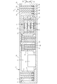
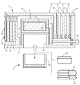
- FIGS. 1 and 2 show Example 1 of a disaster rescue jack according to the present invention.
- a disaster rescue jack is composed mainly of an operation structure 1 for raising a jack-up target and a hydrogen gas supply structure 2 disposed inside the operation structure 1.
- the operation structure 1 includes an operation base 3 placed on an installation surface, and a jack portion 5 that is assembled to the operation base 3 and includes an operation space 4 sealed inside.
- the operating base 3 is formed in a round plate shape that is open upward with a circular bottom wall and a round cylindrical peripheral wall continuously provided on the periphery of the bottom wall, and is formed of a metal material. .
- a retaining wall 3 a projects from the opening edge of the operation base 3 toward the inner surface of the cylinder.
- the jack portion 5 is configured to be extendable by assembling four metal slidable cylinders 6 to 9 that are slidable vertically.
- the lower three telescopic cylinders 6, 7 and 8 are formed in a round cylindrical shape, and retaining walls 6a, 7a and 8a are formed on the inner edges of the upper ends of the cylindrical walls. .
- the uppermost telescopic cylinder 9 is formed in a round dish shape that opens downward.
- a working space 4 is defined by each of the telescopic cylinders 6 to 9 and the above-described working base 3, and a ring-shaped sealing material that prevents hydrogen gas from leaking on the lower peripheral surface of each of the telescopic cylinders 6 to 9. 6b, 7b, 8b and 9b are attached.
- the upper surfaces of the ring-shaped walls to which the sealing materials 6b, 7b, 8b, and 9b are attached are retained by the retaining walls 3a, 6a, 7a, and 8a.
- the entire portion 5 is configured in a telescopic structure.
- Each of the telescopic cylinders 6 to 9 slides upward and is received by the previous retaining walls 3a, 6a, 7a, and 8a (the posture shown in FIG. 1), and a standby position in which the telescopic cylinders 6 to 9 overlap each other. (The state shown in FIG. 2).
- each of the telescopic cylinders 6 to 9 can be stored in the operation base 3.
- the disaster rescue jack at this time has a flat disk shape, and its overall height is 100 mm.
- the ceiling wall of the uppermost telescopic cylinder 9 functions as a push-up unit 10 for raising and lowering a jack-up target such as rubble in a disaster area.
- the diameter of the inner surface of the uppermost telescopic cylinder 9 is 250 mm
- the outer diameter of the working base 3 is 300 mm
- the expansion / contraction stroke of the jack part 5 is about 32 mm
- the volume of the working space 4 at the maximum extension is 19000 cc. .
- the total weight of the disaster rescue jack is 6.6kg, and the jack part 5 can be stored flat in the standby position, so other rescues such as ropes can be used when aiming at the disaster area on foot. Can be carried and transported in a rucksack with the instrument.
- An extension guide structure 15 is provided between the uppermost extension cylinder 9 and the operation base 3 in order to regulate the tilting of each extension cylinder 6 to 9 while following the extension operation of the jack section 5.
- the telescopic guide structure 15 includes four guide cylinders 16 to 19 whose upper and lower surfaces are open, and a guide shaft 20 fixed to the center of the inner surface of the uppermost telescopic cylinder 9.
- the lowermost guide tube 16 is fixed at the center of the operation base 3.
- the guide cylinders 17 to 19 extending upward are guided by the lower guide cylinders 16 to 18 so as to be vertically slidable.
- the guide shaft 20 is guided by the uppermost guide cylinder 19 to be slidable vertically.
- Linear bushings 16a, 17a, 18a, and 19a are fixed to the inner surfaces of the upper ends of the guide cylinders 16 to 19 in order to smoothly slide the guide cylinders 17 to 19 and the guide shaft 20 up and down.
- the entire telescopic guide structure 15 has a telescopic structure, and the guide cylinders 17 to 19 and the guide shaft 20 are fixed to the operation base 3 in a state where the jack portion 5 is in the standby position. 16 can be housed inside.
- the hydrogen gas supply structure 2 includes a hydrogen storage alloy 22 and a heater (heat source) 23, a hydrogen storage chamber 24 that accommodates both of these layers 22, 23 alternately, a battery (secondary battery) 25, and a hydrogen storage It comprises an electromagnetic valve 27 and the like for opening and closing the inlet / outlet 26 of the chamber 24.
- a push button type change-over switch is provided on the peripheral surface of the operating base 3. When the first button 28 is pushed, the current of the battery 25 can be supplied to the heater 23 to heat the hydrogen storage alloy 22, and when the push button is pushed again, the current supply to the battery 25 can be cut off and the operation of the heater 23 can be stopped. .
- the electromagnetic valve 27 is switched to the open state, and the inside of the hydrogen storage chamber 24 and the working space 4 can be communicated.
- the electromagnetic valve 27 is switched to the closed state, The communication state between the inside of the hydrogen storage chamber 24 and the working space 4 can be blocked.
- the disaster rescue jack configured as described above is used in the affected area as follows. First, the operation base 3 is installed with the lower mounting surface to be jacked up. At this time, when the gap between the jack-up target such as rubble and the mounting surface is larger than necessary, timber and concrete blocks are stacked on the mounting surface, and the operation base 3 is installed on the upper surface. Next, the first button 28 is pushed in to operate the heater 23 to heat the hydrogen storage alloy 22 to release hydrogen gas. At the same time, the first button 29 is pushed to switch the electromagnetic valve 27 to the open state, and the hydrogen gas released into the hydrogen storage chamber 24 is sent to the working space 4 through the inlet / outlet 26 and the electromagnetic valve 27. The jack part 5 is extended.
- the central telescopic cylinder 9 When hydrogen gas is supplied to the working space 4, the central telescopic cylinder 9 is first pushed out and raised. Further, when the telescopic cylinder 9 is received by the retaining wall 8 a of the next telescopic cylinder 8, the telescopic cylinder 9 rises while accompanying the telescopic cylinder 8. Similarly, each of the telescopic cylinders 8 to 6 accompanies the uppermost telescopic cylinder 9 and sequentially moves upward, and the push-up unit 10 pushes up the jack-up target.
- the first button 29 When the object to be jacked up is pushed up to the required height, the first button 29 is pushed to stop the energization state of the heater 23, and at the same time, the second button 29 is pushed to switch the solenoid valve 27 to the closed state, thereby closing the entrance 26. . Thereby, it is possible to prevent the hydrogen gas sent into the working space 4 from being adsorbed by the hydrogen storage alloy 22 and to keep the jack portion 5 in the extended posture. In this state, the jack-up target is supported by a column or a concrete block to ensure safety and help victims sandwiched between debris.
- the jack portion 5 When the jack portion 5 is extended to the maximum extension position, this is detected by a sensor (not shown), the energization state of the heater 23 is stopped, and at the same time, the solenoid valve 27 is switched to the closed state and the entrance / exit 26 is shut off. Then, the jack portion 5 is held in the extended posture. In this state, after the fall prevention measures are taken for the jack-up target to ensure safety, the victims sandwiched between rubble and the like are rescued. After rescuing the victim, after removing the column or concrete block that supported the jack-up target, the second button 29 was pushed to switch the electromagnetic valve 27 to the open state, and the hydrogen storage chamber 24 and the working space. 4 is communicated. As a result, hydrogen gas is adsorbed by the hydrogen storage alloy 22, but since this hydrogen adsorption reaction proceeds slowly, the jack portion 5 does not descend rapidly but retracts slowly and is stored in the operating base 3.
- a sensor not shown
- the maximum push-up load of the jack is proportional to the product of the pressure receiving area of the uppermost telescopic cylinder 9 and the pressure of the hydrogen gas fed into the working space 4.
- the push-up portion 10 of the telescopic cylinder 9 is about 0.52 t.
- the push-up force can be demonstrated.
- the push-up portion 10 of the telescopic cylinder 9 can exert a pushing force of about 1.5 t.
- a jack that uses hydrogen gas as the drive medium can output a far greater maximum lifting load than a mechanical screw jack or a pneumatic jack, so it can reliably target a heavier jack-up target at the disaster site. It can be lifted to contribute to disaster relief.
- the hydrogen storage alloy 22 As the hydrogen storage alloy 22, a La—Ni system, a Ca—Ni 5 system, a Mm—Ni system, a Ti—Fe system, or the like can be applied.
- Mm—Ni system Mm is an alloy containing a plurality of rare earths obtained in the rare earth generation process.
- the hydrogen storage alloy 22 When the La—Ni-based hydrogen storage alloy 22 is used and the diameter of the inner surface of the uppermost telescopic cylinder 9 is 250 mm, the hydrogen storage alloy necessary for raising the working space 4 by 1 atm.
- the weight of 22 is around 130 g.
- the disaster relief jack configured as described above, it can be used in disaster sites where it is difficult to obtain electric power and engine fuel, and the jack-up target such as heavy debris is pushed up and sandwiched between the debris. Rescued victims.
- the overall weight is small and the entire jack in the standby position can be held in a flat shape, it can be easily carried on foot and can be brought in securely even in disaster areas where vehicles cannot enter. it can.
- jacks can be installed without any hindrance and used for disaster relief. By simply switching the first and second buttons 28 and 29, the jack-up target such as rubble can be pushed up, so in the case where there are not enough personnel involved in the rescue work, Even if there is, it is possible to perform rescue work by operating the jack.
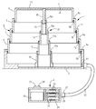
- FIG. 3 shows Example 2 of the disaster rescue jack according to the present invention.
- the hydrogen gas supply structure 2 is provided separately from the operation structure 1 so that the connection port 31 provided in the operation base 3 and the electromagnetic valve 27 communicate with each other through the gas passage 32.
- the interior of the hydrogen storage chamber 24 is divided into two chambers, a battery 25 is disposed on one of the chambers, and a hydrogen storage alloy 22 and a heater 23 are accommodated on the other.
- the changeover switch was disposed on the upper surface of the hydrogen storage chamber 24 using a lid that seals the opening surface. Since others are the same as the previous embodiment, the same reference numerals are assigned to the same members, and descriptions thereof are omitted. The same applies to the following embodiments.
- FIG. 4 shows Example 3 of the disaster rescue jack according to the present invention.
- the bellows 33 is accommodated in the jack portion 5, and the working space 4 is formed in the bellows 33. Further, the hydrogen gas supply structure 2 is arranged inside the working space 4 partitioned by the bellows 33.
- the bellows 33 is formed in a bellows shape with a laminate film or polymer material having high hydrogen-tightness, and its upper end is fixed to the inner surface of the push-up portion 10 of the telescopic cylinder 9 positioned at the uppermost stage, and its lower end is operated. It is fixed to the inner bottom wall of the base 3.
- each of the telescopic cylinders 6 to 9 expands while being tilted due to a bias of the load on the push-up portion 10, and in this case, each of the sealing materials 6a to 9a falls into a poor seal. As a result, hydrogen gas in the working space 4 may leak to the outside.
- the jack portion 5 is composed of the multistage cylindrical expansion and contraction cylinders 6 to 9 and the bellows 33, even if each of the sealing materials 6a to 9a may cause a sealing failure, hydrogen gas Can be reliably prevented from leaking from the working space 4 of the bellows 33.
- the telescopic guide structure 15 in the previous embodiment can be omitted, and further, since it is not necessary to increase the processing accuracy and sealing accuracy of the telescopic cylinders 6 to 9, the cost required for manufacturing the jack as a whole can be reduced.
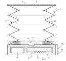
- FIG. 5 shows Example 4 of the disaster rescue jack according to the present invention.
- the jack portion 5 is constituted by a bellows 33, and a plate member is fixed to the upper end of the bellows 33 to form a push-up portion 10.
- the lower end of the bellows 33 is fixed to a lid that seals the opening surface of the hydrogen storage chamber 24, and the inlet / outlet 26 and the electromagnetic valve 27 are arranged on the lid facing the working space 4 in the bellows 33.
- the hydrogen storage chamber 24 also serves as the operation base 3, and in the state where the jack portion 5 is in the standby position, the entire bellows 33 is folded and the push-up portion 10 provided at the upper end is operated. Stored in the vicinity of the base 3.
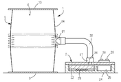
- FIG. 6 shows Example 5 of the disaster rescue jack according to the present invention.
- the jack portion 5 is constituted by a diaphragm 34, and a plate member is fixed to the upper end of the diaphragm 34 to form a push-up portion 10.
- a plate member was fixed to the lower end of the diaphragm 34 to obtain the operation base 3.
- the hydrogen gas supply structure 2 is provided separately from the operation structure 1 so that the electromagnetic valve 27 and the connection port 31 provided in the operation base 3 are communicated with each other through the gas passage 32.
- the diaphragm 34 is formed of a laminate film having a high hydrogen gas tightness or a polymer material.
- FIG. 7 shows Example 6 of the disaster rescue jack according to the present invention.
- a heat source of the hydrogen gas supply structure 2 any one of combustion heat of the solid fuel (heat source) 36 and heat of hydrolysis reaction of quick lime (heat source) 37 and water 38 can be used.
- a heating container 39 for accommodating the solid fuel 36 or quicklime 37 and water 38 is provided, and a recess 40 for loading the heating container 39 is formed in an upper dent shape on the central lower surface of the operation base 3.
- the switching valve 41 provided at the entrance 26 can be switched between an open state and a closed state by an operation rod 42 that can be pushed and pulled.
- the quicklime 37 and the water 38 are accommodated in the heating container 39 in a state of being taken out from the packaging bag.
- the heat of combustion of the solid fuel 36 and the heat of hydrolysis reaction of quicklime 37 and water 38 are conducted to the hydrogen storage alloy 22 through the ceiling wall of the recess 40.
- a pantograph structure can be applied as the telescopic guide structure 15. If necessary, the telescopic guide structure 15 is added to the inside of the working chamber 4 of the jack described with reference to FIGS. can do.
- a laminate film having high hydrogen-tightness or an air bag formed of a polymer material can be applied.
- the jack part 5 can be composed of at least two telescopic cylinders.
- the hydrogen gas supplied from the working space 4 does not need to be re-adsorbed by the hydrogen storage alloy 22 and can be released into the air to retract the jack portion 5.
- the changeover switch does not need to have the structure described in the embodiment, and may be any switch that can control the energization state of the heater 23 and the electromagnetic valve 27.
Landscapes
- Engineering & Computer Science (AREA)
- Mechanical Engineering (AREA)
- Life Sciences & Earth Sciences (AREA)
- Geology (AREA)
- Structural Engineering (AREA)
- Physics & Mathematics (AREA)
- Fluid Mechanics (AREA)
- General Engineering & Computer Science (AREA)
- Filling Or Discharging Of Gas Storage Vessels (AREA)
Abstract
Description
2 水素ガス供給構造
3 作動ベース
4 作動空間
5 ジャッキ部
6~9 伸縮筒
10 押上部
15 伸縮ガイド構造
22 水素吸蔵合金
23 ヒーター(熱源)
24 水素吸蔵チャンバー
25 バッテリー
26 出入口
27 電磁弁
33 ベローズ
Claims (8)
- 水素吸蔵合金(22)を熱源(23)で加熱して、水素吸蔵合金(22)に吸蔵された水素ガスを供給する水素ガス供給構造(2)と、水素ガス供給構造(2)から供給される水素ガスの圧力で伸張して、ジャッキアップ対象を昇揚操作する作動構造(1)とを備えており、
作動構造(1)は、設置面に載置される作動ベース(3)と、作動ベース(3)に組付けられて、内部に密封された作動空間(4)を備えているジャッキ部(5)とを含み、
ジャッキ部(5)は、その上端に設けた押上部(10)が作動ベース(3)の近傍に格納される待機姿勢と、押上部(10)が作動ベース(3)の上方へ突出する伸張姿勢との間で伸縮できるように構成されており、
ジャッキ部(5)を待機姿勢に退縮させた状態において、作動構造(1)の全体を扁平形状に保持できることを特徴とする災害救助用のジャッキ。 - ジャッキ部(5)が、複数個の上下スライド自在な伸縮筒(6~9)を多段筒状に組んで伸縮自在に構成されており、
水素ガス供給構造(2)で供給した水素ガスを作動空間(4)に供給することにより、ジャッキ部(5)を待機姿勢から伸張姿勢に切換えることができる請求項1に記載の災害救助用のジャッキ。 - ジャッキ部(5)の内部に、作動空間(4)を区画するベローズ(33)が収容されており、
ベローズ(33)が、最上段に位置する伸縮筒(9)と、作動ベース(3)との間に配置してある請求項2に記載の災害救助用のジャッキ。 - 作動構造(1)が、伸縮可能なベローズ(33)とダイヤフラム(34)のいずれか一方で構成されるジャッキ部(5)と、ジャッキ部(5)の上端に固定されて押上部(10)を構成する板材と、ジャッキ部(5)の下端に固定される作動ベース(3)とで構成してある請求項1に記載の災害救助用のジャッキ。
- ジャッキ部(5)の伸縮動作に追随しながら、ジャッキ部(5)の傾動を規制する伸縮ガイド構造(15)が作動空間(4)に設けてある請求項2、3または4のいずれかひとつに記載の災害救助用のジャッキ。
- 作動ベース(3)が上向きに開口する皿状に形成されており、
待機姿勢に退縮させた状態のジャッキ部(5)の全体を作動ベース(3)に格納できる請求項1~5のいずれかひとつに記載の災害救助用のジャッキ。 - 水素ガス供給構造(2)が、作動ベース(3)の内部に配置されている請求項1~6のいずれかひとつに記載の災害救助用のジャッキ。
- 水素ガス供給構造(2)の加熱源が、バッテリー(25)を駆動源とするヒーター(23)の電熱と、固形燃料(36)の燃焼熱と、生石灰(37)の加水反応熱と、被災地における可燃廃材の燃焼熱のいずれかひとつである請求項1~7のいずれかひとつに記載の災害救助用のジャッキ。
Priority Applications (3)
| Application Number | Priority Date | Filing Date | Title |
|---|---|---|---|
| US14/009,700 US20140183430A1 (en) | 2011-04-04 | 2011-04-04 | Jack for disaster relief |
| PCT/JP2011/002008 WO2012137246A1 (ja) | 2011-04-04 | 2011-04-04 | 災害救助用のジャッキ |
| JP2013508624A JP5920791B2 (ja) | 2011-04-04 | 2011-04-04 | 災害救助用のジャッキ |
Applications Claiming Priority (1)
| Application Number | Priority Date | Filing Date | Title |
|---|---|---|---|
| PCT/JP2011/002008 WO2012137246A1 (ja) | 2011-04-04 | 2011-04-04 | 災害救助用のジャッキ |
Publications (1)
| Publication Number | Publication Date |
|---|---|
| WO2012137246A1 true WO2012137246A1 (ja) | 2012-10-11 |
Family
ID=46968696
Family Applications (1)
| Application Number | Title | Priority Date | Filing Date |
|---|---|---|---|
| PCT/JP2011/002008 Ceased WO2012137246A1 (ja) | 2011-04-04 | 2011-04-04 | 災害救助用のジャッキ |
Country Status (3)
| Country | Link |
|---|---|
| US (1) | US20140183430A1 (ja) |
| JP (1) | JP5920791B2 (ja) |
| WO (1) | WO2012137246A1 (ja) |
Cited By (3)
| Publication number | Priority date | Publication date | Assignee | Title |
|---|---|---|---|---|
| WO2018105470A1 (ja) * | 2016-12-07 | 2018-06-14 | 圭治郎 山本 | アクチュエータ装置及び関節運動アシスト装置 |
| JP2018095354A (ja) * | 2016-12-09 | 2018-06-21 | 国立研究開発法人産業技術総合研究所 | バッグ型拡開装置 |
| CN110319453A (zh) * | 2019-07-08 | 2019-10-11 | 北京理工大学 | 一种用于细长型燃烧室的可伸缩供气管道 |
Families Citing this family (8)
| Publication number | Priority date | Publication date | Assignee | Title |
|---|---|---|---|---|
| US20160161051A1 (en) * | 2014-12-05 | 2016-06-09 | Roberto SALIN | System with extendable retractable telescopic elements depending on a lifting mechanism, lockable and unlockable mechanically and automatically |
| CN105003487B (zh) * | 2015-08-13 | 2017-03-15 | 北京中金泰达电液科技有限公司 | 低摩擦无旋转垂直单作用伺服多级伸缩缸 |
| EP3165270B1 (en) * | 2015-11-03 | 2018-07-18 | Carbon Air Limited | Temperature-governed pressure adjustment in pneumatic structures |
| JP6716814B2 (ja) * | 2016-02-17 | 2020-07-01 | 静岡県 | 伸縮セルモジュールおよび緩衝デバイス |
| CN112645232B (zh) * | 2020-12-23 | 2022-09-06 | 库卡机器人(广东)有限公司 | 顶升装置 |
| KR200499594Y1 (ko) * | 2023-12-13 | 2025-09-18 | (주)포스코퓨처엠 | 밀폐공간 작업중 비상시 인력 구출장비 |
| DE102024105760A1 (de) * | 2024-02-29 | 2025-09-04 | Vetter Gmbh | Hebekissen mit integrierter Hubmessung |
| DE102024105761A1 (de) * | 2024-02-29 | 2025-09-04 | Vetter Gmbh | Smarte Überwachung eines Hubvorgangs mit pneumatischem Hebekissen |
Citations (5)
| Publication number | Priority date | Publication date | Assignee | Title |
|---|---|---|---|---|
| JPS5296083U (ja) * | 1976-01-14 | 1977-07-18 | ||
| JPS52100328U (ja) * | 1976-01-27 | 1977-07-29 | ||
| JPH02225296A (ja) * | 1989-02-27 | 1990-09-07 | Bridgestone Corp | 流体圧ジャッキ |
| JPH0826700A (ja) * | 1994-07-21 | 1996-01-30 | Matsushita Electric Ind Co Ltd | 昇降装置 |
| JPH08324983A (ja) * | 1995-05-30 | 1996-12-10 | Nippon Kayaku Co Ltd | 緊急救助用エアジャッキ |
Family Cites Families (4)
| Publication number | Priority date | Publication date | Assignee | Title |
|---|---|---|---|---|
| US3693346A (en) * | 1971-05-28 | 1972-09-26 | Nasa | Gas operated actuator |
| US6907817B2 (en) * | 2002-07-11 | 2005-06-21 | Autoliv Asp, Inc. | Linear actuator |
| JP2007284247A (ja) * | 2006-04-12 | 2007-11-01 | Takeshi Shimizu | 複合加圧二段ジャッキ |
| US7975986B2 (en) * | 2007-05-03 | 2011-07-12 | 2111091 Ontario Ltd. | All-air vehicle lifting jack |
-
2011
- 2011-04-04 US US14/009,700 patent/US20140183430A1/en not_active Abandoned
- 2011-04-04 WO PCT/JP2011/002008 patent/WO2012137246A1/ja not_active Ceased
- 2011-04-04 JP JP2013508624A patent/JP5920791B2/ja active Active
Patent Citations (5)
| Publication number | Priority date | Publication date | Assignee | Title |
|---|---|---|---|---|
| JPS5296083U (ja) * | 1976-01-14 | 1977-07-18 | ||
| JPS52100328U (ja) * | 1976-01-27 | 1977-07-29 | ||
| JPH02225296A (ja) * | 1989-02-27 | 1990-09-07 | Bridgestone Corp | 流体圧ジャッキ |
| JPH0826700A (ja) * | 1994-07-21 | 1996-01-30 | Matsushita Electric Ind Co Ltd | 昇降装置 |
| JPH08324983A (ja) * | 1995-05-30 | 1996-12-10 | Nippon Kayaku Co Ltd | 緊急救助用エアジャッキ |
Cited By (3)
| Publication number | Priority date | Publication date | Assignee | Title |
|---|---|---|---|---|
| WO2018105470A1 (ja) * | 2016-12-07 | 2018-06-14 | 圭治郎 山本 | アクチュエータ装置及び関節運動アシスト装置 |
| JP2018095354A (ja) * | 2016-12-09 | 2018-06-21 | 国立研究開発法人産業技術総合研究所 | バッグ型拡開装置 |
| CN110319453A (zh) * | 2019-07-08 | 2019-10-11 | 北京理工大学 | 一种用于细长型燃烧室的可伸缩供气管道 |
Also Published As
| Publication number | Publication date |
|---|---|
| JP5920791B2 (ja) | 2016-05-18 |
| US20140183430A1 (en) | 2014-07-03 |
| JPWO2012137246A1 (ja) | 2014-07-28 |
Similar Documents
| Publication | Publication Date | Title |
|---|---|---|
| JP5920791B2 (ja) | 災害救助用のジャッキ | |
| US8813916B2 (en) | Underground enclosure system for storing components, cables, and the like | |
| US8367232B2 (en) | Venting system for an underground enclosure | |
| EA010819B1 (ru) | Аккумулятор давления для создания мощности, достаточной для приведения в действие и функционирования внешнего оборудования, а также его применение | |
| US3832937A (en) | Pneumatic telescopic hoist having three or more steps of extension | |
| CN104136784B (zh) | 锁定延伸设备 | |
| US3622124A (en) | Hydraulic lift jack | |
| CN101817484A (zh) | 万向手动液压千斤顶 | |
| US4605203A (en) | Pneumatic jack | |
| CN211110870U (zh) | 架车机 | |
| JP7010440B2 (ja) | シリンダ及び昇降装置 | |
| EP0547909A1 (en) | Counterbalance actuator | |
| EP2616381B1 (en) | A hoisting device and a component module for a hoisting or transferring device | |
| CN103807489B (zh) | 一种气液联动快速作动缸 | |
| WO2006134324A2 (en) | Improvements in or relating to drive systems | |
| US20070256898A1 (en) | Drive Systems | |
| JPH09203495A (ja) | 乾式ガスホルダー | |
| GB2475295A (en) | Energy storage apparatus with two linked chambers | |
| Sato et al. | Development of a new portable rescue tool using metal hydride alloys | |
| JPH0826700A (ja) | 昇降装置 | |
| CN100451354C (zh) | 油压或水液压的液压缸 | |
| CN111379761B (zh) | 油缸、液压系统及举升设备 | |
| CN115218113A (zh) | 一种分层式储气装置及重力压缩空气储能系统 | |
| CN114589711A (zh) | 一种用于火场液化气瓶抢险的消防机器人 | |
| JP6683975B2 (ja) | シリンダ |
Legal Events
| Date | Code | Title | Description |
|---|---|---|---|
| 121 | Ep: the epo has been informed by wipo that ep was designated in this application |
Ref document number: 11863250 Country of ref document: EP Kind code of ref document: A1 |
|
| ENP | Entry into the national phase |
Ref document number: 2013508624 Country of ref document: JP Kind code of ref document: A |
|
| NENP | Non-entry into the national phase |
Ref country code: DE |
|
| WWE | Wipo information: entry into national phase |
Ref document number: 14009700 Country of ref document: US |
|
| 122 | Ep: pct application non-entry in european phase |
Ref document number: 11863250 Country of ref document: EP Kind code of ref document: A1 |