WO2012133104A1 - Hydraulic system for hydraulic working machine - Google Patents
Hydraulic system for hydraulic working machine Download PDFInfo
- Publication number
- WO2012133104A1 WO2012133104A1 PCT/JP2012/057329 JP2012057329W WO2012133104A1 WO 2012133104 A1 WO2012133104 A1 WO 2012133104A1 JP 2012057329 W JP2012057329 W JP 2012057329W WO 2012133104 A1 WO2012133104 A1 WO 2012133104A1
- Authority
- WO
- WIPO (PCT)
- Prior art keywords
- pressure
- oil passage
- hydraulic
- motor
- pressure detection
- Prior art date
Links
Images


Classifications
-
- E—FIXED CONSTRUCTIONS
- E02—HYDRAULIC ENGINEERING; FOUNDATIONS; SOIL SHIFTING
- E02F—DREDGING; SOIL-SHIFTING
- E02F9/00—Component parts of dredgers or soil-shifting machines, not restricted to one of the kinds covered by groups E02F3/00 - E02F7/00
- E02F9/20—Drives; Control devices
- E02F9/22—Hydraulic or pneumatic drives
- E02F9/2221—Control of flow rate; Load sensing arrangements
- E02F9/2232—Control of flow rate; Load sensing arrangements using one or more variable displacement pumps
- E02F9/2235—Control of flow rate; Load sensing arrangements using one or more variable displacement pumps including an electronic controller
-
- F—MECHANICAL ENGINEERING; LIGHTING; HEATING; WEAPONS; BLASTING
- F15—FLUID-PRESSURE ACTUATORS; HYDRAULICS OR PNEUMATICS IN GENERAL
- F15B—SYSTEMS ACTING BY MEANS OF FLUIDS IN GENERAL; FLUID-PRESSURE ACTUATORS, e.g. SERVOMOTORS; DETAILS OF FLUID-PRESSURE SYSTEMS, NOT OTHERWISE PROVIDED FOR
- F15B9/00—Servomotors with follow-up action, e.g. obtained by feed-back control, i.e. in which the position of the actuated member conforms with that of the controlling member
- F15B9/02—Servomotors with follow-up action, e.g. obtained by feed-back control, i.e. in which the position of the actuated member conforms with that of the controlling member with servomotors of the reciprocatable or oscillatable type
- F15B9/08—Servomotors with follow-up action, e.g. obtained by feed-back control, i.e. in which the position of the actuated member conforms with that of the controlling member with servomotors of the reciprocatable or oscillatable type controlled by valves affecting the fluid feed or the fluid outlet of the servomotor
-
- E—FIXED CONSTRUCTIONS
- E02—HYDRAULIC ENGINEERING; FOUNDATIONS; SOIL SHIFTING
- E02F—DREDGING; SOIL-SHIFTING
- E02F9/00—Component parts of dredgers or soil-shifting machines, not restricted to one of the kinds covered by groups E02F3/00 - E02F7/00
- E02F9/20—Drives; Control devices
- E02F9/22—Hydraulic or pneumatic drives
- E02F9/2221—Control of flow rate; Load sensing arrangements
- E02F9/2239—Control of flow rate; Load sensing arrangements using two or more pumps with cross-assistance
- E02F9/2242—Control of flow rate; Load sensing arrangements using two or more pumps with cross-assistance including an electronic controller
-
- E—FIXED CONSTRUCTIONS
- E02—HYDRAULIC ENGINEERING; FOUNDATIONS; SOIL SHIFTING
- E02F—DREDGING; SOIL-SHIFTING
- E02F9/00—Component parts of dredgers or soil-shifting machines, not restricted to one of the kinds covered by groups E02F3/00 - E02F7/00
- E02F9/20—Drives; Control devices
- E02F9/22—Hydraulic or pneumatic drives
- E02F9/2278—Hydraulic circuits
- E02F9/2285—Pilot-operated systems
-
- E—FIXED CONSTRUCTIONS
- E02—HYDRAULIC ENGINEERING; FOUNDATIONS; SOIL SHIFTING
- E02F—DREDGING; SOIL-SHIFTING
- E02F9/00—Component parts of dredgers or soil-shifting machines, not restricted to one of the kinds covered by groups E02F3/00 - E02F7/00
- E02F9/20—Drives; Control devices
- E02F9/22—Hydraulic or pneumatic drives
- E02F9/2278—Hydraulic circuits
- E02F9/2292—Systems with two or more pumps
-
- E—FIXED CONSTRUCTIONS
- E02—HYDRAULIC ENGINEERING; FOUNDATIONS; SOIL SHIFTING
- E02F—DREDGING; SOIL-SHIFTING
- E02F9/00—Component parts of dredgers or soil-shifting machines, not restricted to one of the kinds covered by groups E02F3/00 - E02F7/00
- E02F9/20—Drives; Control devices
- E02F9/22—Hydraulic or pneumatic drives
- E02F9/2278—Hydraulic circuits
- E02F9/2296—Systems with a variable displacement pump
-
- F—MECHANICAL ENGINEERING; LIGHTING; HEATING; WEAPONS; BLASTING
- F15—FLUID-PRESSURE ACTUATORS; HYDRAULICS OR PNEUMATICS IN GENERAL
- F15B—SYSTEMS ACTING BY MEANS OF FLUIDS IN GENERAL; FLUID-PRESSURE ACTUATORS, e.g. SERVOMOTORS; DETAILS OF FLUID-PRESSURE SYSTEMS, NOT OTHERWISE PROVIDED FOR
- F15B11/00—Servomotor systems without provision for follow-up action; Circuits therefor
- F15B11/02—Systems essentially incorporating special features for controlling the speed or actuating force of an output member
-
- F—MECHANICAL ENGINEERING; LIGHTING; HEATING; WEAPONS; BLASTING
- F15—FLUID-PRESSURE ACTUATORS; HYDRAULICS OR PNEUMATICS IN GENERAL
- F15B—SYSTEMS ACTING BY MEANS OF FLUIDS IN GENERAL; FLUID-PRESSURE ACTUATORS, e.g. SERVOMOTORS; DETAILS OF FLUID-PRESSURE SYSTEMS, NOT OTHERWISE PROVIDED FOR
- F15B11/00—Servomotor systems without provision for follow-up action; Circuits therefor
- F15B11/08—Servomotor systems without provision for follow-up action; Circuits therefor with only one servomotor
-
- F—MECHANICAL ENGINEERING; LIGHTING; HEATING; WEAPONS; BLASTING
- F15—FLUID-PRESSURE ACTUATORS; HYDRAULICS OR PNEUMATICS IN GENERAL
- F15B—SYSTEMS ACTING BY MEANS OF FLUIDS IN GENERAL; FLUID-PRESSURE ACTUATORS, e.g. SERVOMOTORS; DETAILS OF FLUID-PRESSURE SYSTEMS, NOT OTHERWISE PROVIDED FOR
- F15B21/00—Common features of fluid actuator systems; Fluid-pressure actuator systems or details thereof, not covered by any other group of this subclass
- F15B21/14—Energy-recuperation means
-
- F—MECHANICAL ENGINEERING; LIGHTING; HEATING; WEAPONS; BLASTING
- F15—FLUID-PRESSURE ACTUATORS; HYDRAULICS OR PNEUMATICS IN GENERAL
- F15B—SYSTEMS ACTING BY MEANS OF FLUIDS IN GENERAL; FLUID-PRESSURE ACTUATORS, e.g. SERVOMOTORS; DETAILS OF FLUID-PRESSURE SYSTEMS, NOT OTHERWISE PROVIDED FOR
- F15B2211/00—Circuits for servomotor systems
- F15B2211/20—Fluid pressure source, e.g. accumulator or variable axial piston pump
- F15B2211/205—Systems with pumps
- F15B2211/20507—Type of prime mover
-
- F—MECHANICAL ENGINEERING; LIGHTING; HEATING; WEAPONS; BLASTING
- F15—FLUID-PRESSURE ACTUATORS; HYDRAULICS OR PNEUMATICS IN GENERAL
- F15B—SYSTEMS ACTING BY MEANS OF FLUIDS IN GENERAL; FLUID-PRESSURE ACTUATORS, e.g. SERVOMOTORS; DETAILS OF FLUID-PRESSURE SYSTEMS, NOT OTHERWISE PROVIDED FOR
- F15B2211/00—Circuits for servomotor systems
- F15B2211/20—Fluid pressure source, e.g. accumulator or variable axial piston pump
- F15B2211/205—Systems with pumps
- F15B2211/2053—Type of pump
- F15B2211/20546—Type of pump variable capacity
-
- F—MECHANICAL ENGINEERING; LIGHTING; HEATING; WEAPONS; BLASTING
- F15—FLUID-PRESSURE ACTUATORS; HYDRAULICS OR PNEUMATICS IN GENERAL
- F15B—SYSTEMS ACTING BY MEANS OF FLUIDS IN GENERAL; FLUID-PRESSURE ACTUATORS, e.g. SERVOMOTORS; DETAILS OF FLUID-PRESSURE SYSTEMS, NOT OTHERWISE PROVIDED FOR
- F15B2211/00—Circuits for servomotor systems
- F15B2211/60—Circuit components or control therefor
- F15B2211/63—Electronic controllers
- F15B2211/6303—Electronic controllers using input signals
- F15B2211/6306—Electronic controllers using input signals representing a pressure
- F15B2211/6313—Electronic controllers using input signals representing a pressure the pressure being a load pressure
-
- F—MECHANICAL ENGINEERING; LIGHTING; HEATING; WEAPONS; BLASTING
- F15—FLUID-PRESSURE ACTUATORS; HYDRAULICS OR PNEUMATICS IN GENERAL
- F15B—SYSTEMS ACTING BY MEANS OF FLUIDS IN GENERAL; FLUID-PRESSURE ACTUATORS, e.g. SERVOMOTORS; DETAILS OF FLUID-PRESSURE SYSTEMS, NOT OTHERWISE PROVIDED FOR
- F15B2211/00—Circuits for servomotor systems
- F15B2211/60—Circuit components or control therefor
- F15B2211/63—Electronic controllers
- F15B2211/6303—Electronic controllers using input signals
- F15B2211/6306—Electronic controllers using input signals representing a pressure
- F15B2211/6316—Electronic controllers using input signals representing a pressure the pressure being a pilot pressure
-
- F—MECHANICAL ENGINEERING; LIGHTING; HEATING; WEAPONS; BLASTING
- F15—FLUID-PRESSURE ACTUATORS; HYDRAULICS OR PNEUMATICS IN GENERAL
- F15B—SYSTEMS ACTING BY MEANS OF FLUIDS IN GENERAL; FLUID-PRESSURE ACTUATORS, e.g. SERVOMOTORS; DETAILS OF FLUID-PRESSURE SYSTEMS, NOT OTHERWISE PROVIDED FOR
- F15B2211/00—Circuits for servomotor systems
- F15B2211/60—Circuit components or control therefor
- F15B2211/63—Electronic controllers
- F15B2211/6303—Electronic controllers using input signals
- F15B2211/632—Electronic controllers using input signals representing a flow rate
- F15B2211/6326—Electronic controllers using input signals representing a flow rate the flow rate being an output member flow rate
-
- F—MECHANICAL ENGINEERING; LIGHTING; HEATING; WEAPONS; BLASTING
- F15—FLUID-PRESSURE ACTUATORS; HYDRAULICS OR PNEUMATICS IN GENERAL
- F15B—SYSTEMS ACTING BY MEANS OF FLUIDS IN GENERAL; FLUID-PRESSURE ACTUATORS, e.g. SERVOMOTORS; DETAILS OF FLUID-PRESSURE SYSTEMS, NOT OTHERWISE PROVIDED FOR
- F15B2211/00—Circuits for servomotor systems
- F15B2211/70—Output members, e.g. hydraulic motors or cylinders or control therefor
- F15B2211/705—Output members, e.g. hydraulic motors or cylinders or control therefor characterised by the type of output members or actuators
- F15B2211/7058—Rotary output members
-
- F—MECHANICAL ENGINEERING; LIGHTING; HEATING; WEAPONS; BLASTING
- F15—FLUID-PRESSURE ACTUATORS; HYDRAULICS OR PNEUMATICS IN GENERAL
- F15B—SYSTEMS ACTING BY MEANS OF FLUIDS IN GENERAL; FLUID-PRESSURE ACTUATORS, e.g. SERVOMOTORS; DETAILS OF FLUID-PRESSURE SYSTEMS, NOT OTHERWISE PROVIDED FOR
- F15B2211/00—Circuits for servomotor systems
- F15B2211/70—Output members, e.g. hydraulic motors or cylinders or control therefor
- F15B2211/71—Multiple output members, e.g. multiple hydraulic motors or cylinders
- F15B2211/7114—Multiple output members, e.g. multiple hydraulic motors or cylinders with direct connection between the chambers of different actuators
- F15B2211/7128—Multiple output members, e.g. multiple hydraulic motors or cylinders with direct connection between the chambers of different actuators the chambers being connected in parallel
-
- F—MECHANICAL ENGINEERING; LIGHTING; HEATING; WEAPONS; BLASTING
- F15—FLUID-PRESSURE ACTUATORS; HYDRAULICS OR PNEUMATICS IN GENERAL
- F15B—SYSTEMS ACTING BY MEANS OF FLUIDS IN GENERAL; FLUID-PRESSURE ACTUATORS, e.g. SERVOMOTORS; DETAILS OF FLUID-PRESSURE SYSTEMS, NOT OTHERWISE PROVIDED FOR
- F15B2211/00—Circuits for servomotor systems
- F15B2211/70—Output members, e.g. hydraulic motors or cylinders or control therefor
- F15B2211/76—Control of force or torque of the output member
- F15B2211/763—Control of torque of the output member by means of a variable capacity motor, i.e. by a secondary control on the motor
-
- F—MECHANICAL ENGINEERING; LIGHTING; HEATING; WEAPONS; BLASTING
- F15—FLUID-PRESSURE ACTUATORS; HYDRAULICS OR PNEUMATICS IN GENERAL
- F15B—SYSTEMS ACTING BY MEANS OF FLUIDS IN GENERAL; FLUID-PRESSURE ACTUATORS, e.g. SERVOMOTORS; DETAILS OF FLUID-PRESSURE SYSTEMS, NOT OTHERWISE PROVIDED FOR
- F15B2211/00—Circuits for servomotor systems
- F15B2211/80—Other types of control related to particular problems or conditions
- F15B2211/88—Control measures for saving energy
Definitions
- the flow rate control valve by setting the flow rates of the flow control oil passage and the power regeneration oil passage to a fixed ratio, a flow rate is always generated in the flow control oil passage when the actuator is operating. Therefore, when the flow rate control valve is adjusted by lever operation to change the flow rate change of the flow rate control oil passage, the change in the flow rate necessarily affects the speed of the actuator. Therefore, according to the present invention, the spool type flow rate control valve The good response is reflected. Furthermore, according to the present invention, since the flow ratio between the flow control oil passage and the power regeneration oil passage is always constant, the speed change amount of the actuator is always constant with respect to the flow change amount of the flow control oil passage due to lever operation.
- the actuator 14 is, for example, the boom cylinder 4a described above, that is, a double-acting single rod hydraulic cylinder, and is connected to the hydraulic pump 12 serving as a power source via a flow control valve 19.
- the flow control valve 19 is a three-position, four-port hydraulic pilot switching valve that operates with a pilot pressure adjusted by the pilot valve 16. When the pilot valve 16 is operated to the A side by the lever 15, the right side of the flow rate control valve 19 in this figure becomes a high pressure, and the spool of the flow rate control valve 19 moves to the left side.
- variable displacement motor 23 when pressure oil is flowing into the input port of the variable capacity motor 23, the motor acts to generate the driving torque of the hydraulic pump 12 and assist the rotational power generation means 11, but sufficient hydraulic oil flows. When there is no oil, the hydraulic oil is sucked up from the makeup oil passage 29 to act as a pump, so that torque is absorbed (loss).
- the variable displacement motor 23 in order to minimize the loss in this case, is composed of a variable displacement motor having a minimum displacement of zero (no hydraulic oil is sucked or discharged even if the motor rotates). Yes.
- the electric signal of the flow meter 27 is converted into the flow rate Q1 of the flow control oil passage 21 and multiplied by the flow rate ratio ⁇ between the flow control oil passage 21 and the power regeneration oil passage 22 set in advance to obtain the power regeneration oil.
- the target flow rate Qt2 of the power regeneration oil passage 22 calculated in this way is compared with the actual flow rate Q2 of the power regeneration oil passage 22 obtained by converting the electric signal of the flow meter 28.
- variable displacement motor 23 since the control of the variable displacement motor 23 is feedforward controlled (predictive control) by the lever operation amount (pilot pressure Pp), a control delay of the variable displacement motor 23 occurs. It is difficult and has excellent response to lever operation.
- the motor capacity control spool 51 is connected to the pilot port of the motor capacity control cylinder 50, and the pilot pump 13 is connected to the motor capacity control spool 51. Further, a first pressure detection oil passage 52 and a second pressure detection oil passage 53 are connected to both ends of the motor capacity control spool 51, and the spool moves in accordance with a pressure difference between the two pressure detection oil passages 52 and 53. It is like that. When the pressure P1 of the first pressure detection oil passage 52 is high, the spool moves to the right, the pilot pump 13 is connected to the pilot port of the motor capacity control cylinder 50, and the motor capacity decreases.
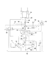
- a fifth embodiment of the present invention will be described with reference to FIG.
- a pressure gauge 70 for detecting the pressure of the branching portion 46 of the hydraulic oil discharge oil passage 20 and the power regeneration oil passage 22 is provided.
- the flow rate ratio between the flow control oil passage 21 and the power regeneration oil passage 22 can be set to an arbitrary ratio regardless of the equivalent throttle 44 and the equivalent throttle 45.
- a method for setting an arbitrary flow rate ratio will be described.
- a sixth embodiment of the present invention will be described with reference to FIG.
- a third pressure detection oil passage 80 for detecting the pressure of the branching portion 46 of the hydraulic oil discharge oil passage 20 and the power regeneration oil passage 22 is provided, and a motor capacity control spool is provided. 51 is connected to both ends. Two pairs of pressure receiving portions are provided at both ends of the motor capacity control spool 51, and their pressure receiving areas are AP1 and AP2.
- variable displacement motor 23 is mechanically connected to the rotational power generation means 11 via the hydraulic pump 12, but the present invention is not limited to such a configuration.
- the variable capacity motor 23 may be connected to a generator provided separately from the rotational power generation means 11.
Abstract
Description
このような油圧作業機の油圧システムについて、特許文献1に開示されている油圧ショベルの例を用いて説明する。 Power regeneration technology is used to improve the efficiency of the hydraulic system of the hydraulic working machine.
A hydraulic system for such a hydraulic working machine will be described using an example of a hydraulic excavator disclosed in
Q1=C・A01√{2(Pa-P1)/ρ}
Q2=C・A02√{2(Pa-P2)/ρ}
C:流量係数,ρ:作動密度
と表わすことができ、Q1、Q2の関係は、
Q2=Q1・(A02/A01)・√{(Pa-P2)/(Pa-P1)}
となる。ここで、P1とP2が同じ圧力である場合、
√{(Pa-P2)/(Pa-P1)}=1
であるから、
Q2=Q1・(A02/A01)
となり、Q1、Q2の流量比が、等価絞り44、等価絞り45等価開口面積比で決まることが分かる。ここで、等価絞り44、等価絞り45は管路抵抗であり、これらの等価開口面積は固定的な数値となるので、Q1、Q2の流量比は固定比率に制御されることになる。 Here, the relationship between controlling P1 and P2 to be substantially equal and the flow rates of the flow rate
Q1 = C · A01√ {2 (Pa−P1) / ρ}
Q2 = C · A02√ {2 (Pa−P2) / ρ}
C: flow coefficient, ρ: working density, and the relationship between Q1 and Q2 is
Q2 = Q1 · (A02 / A01) · √ {(Pa−P2) / (Pa−P1)}
It becomes. Here, when P1 and P2 are the same pressure,
√ {(Pa−P2) / (Pa−P1)} = 1
Because
Q2 = Q1 · (A02 / A01)
Thus, it can be seen that the flow rate ratio between Q1 and Q2 is determined by the equivalent aperture area ratio of the
Q2=α・Q1
である。また、各圧力との関係は、
Q2=Q1・(A02/A01)・√{(Pa-P2)/(Pa-P1)}
であるので、
α=(A02/A01)・√{(Pa-P2)/(Pa-P1)}
となり、式を変形すると、
P2=Pa-(α2・A012/A022)・(Pa-P1)・・・・・(式3)
となる。 The target flow rate Q2 of the power
Q2 = α ・ Q1
It is. The relationship with each pressure is
Q2 = Q1 · (A02 / A01) · √ {(Pa−P2) / (Pa−P1)}
So
α = (A02 / A01) · √ {(Pa−P2) / (Pa−P1)}
And transforming the formula,
P2 = Pa− (α 2 · A01 2 / A02 2 ) · (Pa−P1) (Equation 3)
It becomes.
したがって、スプールストロークがゼロ(中央位置)になるための条件は、
AP1(Pa-P1)-AP2(Pa-P2)=0
であり、式を変形すると、
(Pa-P2)/(Pa-P1)=AP1/AP2
となる。また、Q1とQ2の関係は、
Q2=Q1・(A02/A01)・√{(Pa-P2)/(Pa-P1)}
であるから、
Q2=Q1・(A02/A01)・√(AP1/AP2)
となる。このように、Q1とQ2の流量比は、等価絞り44,45の等価開口面積比と、モータ容量制御スプール51の両端の受圧面積比にて決まる。これはつまり、Q1とQ2の流量比を、等価絞り44,45の等価開口面積比に限定されずに、モータ容量制御スプール51の両端の受圧面積比にて任意に設定可能なことを意味している。 S = {AP1 (Pa−P1) −AP2 (Pa−P2)} / k
Therefore, the condition for the spool stroke to be zero (center position) is
AP1 (Pa−P1) −AP2 (Pa−P2) = 0
And transforming the formula,
(Pa−P2) / (Pa−P1) = AP1 / AP2
It becomes. The relationship between Q1 and Q2 is
Q2 = Q1 · (A02 / A01) · √ {(Pa−P2) / (Pa−P1)}
Because
Q2 = Q1 · (A02 / A01) · √ (AP1 / AP2)
It becomes. Thus, the flow rate ratio between Q1 and Q2 is determined by the equivalent opening area ratio of the equivalent throttles 44 and 45 and the pressure receiving area ratio at both ends of the motor
2 旋回体
3 作業装置
4 ブーム
4a ブームシリンダ
11 回転動力生成手段
12 油圧ポンプ
13 パイロットポンプ
14 アクチュエータ
15 レバー
16 パイロット弁
17 パイロットリリーフ弁
18 作動油タンク
19 流量制御弁
20 作動油排出油路
21 流量制御油路
22 動力回生油路
23 可変容量モータ(動力回生手段)
24 切換弁
25 コントローラ
26 電子制御レギュレータ
27 流量計
28 流量計
29 メイクアップ油路
30 圧力計
31 圧力計
35 パイロットライン
40 圧力計
41 検出部
43 分岐部
44 等価絞り
45 等価絞り
46 分岐部
50 モータ容量制御シリンダ
51 モータ容量制御スプール
52 第1圧力検出油路
53 第2圧力検出油路
54 切換弁
55 切換弁
70 圧力計
80 第3圧力検出油路 DESCRIPTION OF
24
Claims (7)
- 回転動力生成手段から油圧ポンプに回転動力を投入して油圧動力を生成し、その油圧動力によってアクチュエータを動作させる油圧作業機の油圧システムにおいて、
上記アクチュエータからの作動油排出油路を、レバー操作によって制御される流量制御スプールに接続する油路である流量制御油路と、排出作動油の油圧動力を再利用可能なエネルギーに変換する動力回生手段に接続する油路である動力回生油路に分岐し、レバー操作によって上記流量制御油路に発生した流量に対して、上記動力回生油路の流量があらかじめ設定した固定比率になるように上記動力回生手段を制御する回生比率制御手段を設けたことを特徴とする油圧作業機の油圧システム。 In a hydraulic system of a hydraulic working machine that generates hydraulic power by supplying rotational power from a rotational power generating means to a hydraulic pump and operates an actuator by the hydraulic power,
A flow rate control oil path that is an oil path connecting the hydraulic oil discharge oil path from the actuator to a flow rate control spool controlled by lever operation, and a power regeneration that converts the hydraulic power of the discharged hydraulic oil into reusable energy. Branching to a power regeneration oil passage that is an oil passage connected to the means, the flow rate of the power regeneration oil passage is set to a fixed ratio set in advance with respect to the flow rate generated in the flow control oil passage by lever operation. A hydraulic system for a hydraulic working machine, comprising a regeneration ratio control means for controlling a power regeneration means. - 請求項1に記載の油圧作業機の油圧システムにおいて、
上記動力回生手段を可変容量モータとし、
上記回生比率制御手段が、上記操作レバーによって生成した操作パイロット圧と上記アクチュエータからの上記作動油排出油路の圧力および上記可変容量モータの回転速度から、上記流量制御油路と上記動力回生油路の流量が固定比率になるような上記可変容量モータの目標容量を計算するコントローラと、このコントローラからの電気指令によって上記可変容量モータの容量を制御するモータ容量制御手段とから成ることを特徴とする油圧作業機の油圧システム。 In the hydraulic system of the hydraulic working machine according to claim 1,
The power regeneration means is a variable capacity motor,
The flow rate control oil path and the power regeneration oil path are determined by the regeneration ratio control means from the operation pilot pressure generated by the operation lever, the pressure of the hydraulic oil discharge oil path from the actuator, and the rotational speed of the variable capacity motor. A controller for calculating the target capacity of the variable capacity motor so that the flow rate of the motor is a fixed ratio, and motor capacity control means for controlling the capacity of the variable capacity motor in accordance with an electrical command from the controller. Hydraulic system for hydraulic working machines. - 請求項1に記載の油圧作業機の油圧システムにおいて、
上記動力回生手段を可変容量モータとし、
上記回生比率制御手段が、上記流量制御油路に設けた第1圧力検出手段と上記動力回生油路に設けた第2圧力検出手段、および、上記第1圧力検出手段の圧力が上記第2圧力検出手段の圧力よりも大きい場合に上記可変容量モータの容量を小さくし、上記第1圧力検出手段の圧力が上記第2圧力検出手段の圧力よりも小さい場合に上記可変容量モータの容量を大きくし、上記第1圧力検出手段と上記第2圧力検出手段の圧力が同じ場合に上記可変容量モータの容量を固定するモータ容量制御手段とから成ることを特徴とする油圧作業機の油圧システム。 In the hydraulic system of the hydraulic working machine according to claim 1,
The power regeneration means is a variable capacity motor,
The regeneration ratio control means includes a first pressure detection means provided in the flow rate control oil passage, a second pressure detection means provided in the power regeneration oil passage, and a pressure of the first pressure detection means is the second pressure. The capacity of the variable capacity motor is reduced when the pressure is higher than the pressure of the detection means, and the capacity of the variable capacity motor is increased when the pressure of the first pressure detection means is lower than the pressure of the second pressure detection means. A hydraulic system for a hydraulic working machine comprising: motor capacity control means for fixing the capacity of the variable capacity motor when the pressures of the first pressure detection means and the second pressure detection means are the same. - 請求項3に記載の油圧作業機の油圧システムにおいて、
上記第1圧力検出手段が上記流量制御油路から分岐する第1圧力検出油路から成り、上記第2圧力検出手段が上記動力回生油路から分岐する第2圧力検出油路から成り、モータ容量制御手段がモータ容量制御スプールとモータ容量制御シリンダから成り、上記モータ容量制御スプール両端に設けた同じ面積をもつ受圧部に、上記第1圧力検出油路と上記第2圧力検出油路を対抗させて接続することで、上記第1圧力検出油路と上記第2圧力検出油路の圧力関係によって上記モータ容量制御スプールが移動し、さらに、上記モータ容量制御スプールが移動することによって、上記モータ容量制御シリンダへの圧油の給排を切り換え、上記可変容量モータの容量を制御することを特徴とする油圧作業機の油圧システム。 In the hydraulic system of the hydraulic working machine according to claim 3,
The first pressure detection means comprises a first pressure detection oil passage branched from the flow control oil passage, the second pressure detection means comprises a second pressure detection oil passage branched from the power regeneration oil passage, and motor capacity The control means comprises a motor capacity control spool and a motor capacity control cylinder, and the first pressure detection oil path and the second pressure detection oil path are opposed to pressure receiving portions having the same area provided at both ends of the motor capacity control spool. By connecting the motor capacity control spool, the motor capacity control spool moves according to the pressure relationship between the first pressure detection oil path and the second pressure detection oil path. A hydraulic system for a hydraulic working machine, wherein the supply and discharge of pressure oil to and from a control cylinder is switched to control the capacity of the variable displacement motor. - 請求項1に記載の油圧作業機の油圧システムにおいて、
上記動力回生手段を可変容量モータとし、
上記回生比率制御手段が、上記流量制御油路に設けた第1圧力検出手段、上記動力回生油路に設けた第2圧力検出手段、および、上記作動油排出油路に設けた第3圧力検出手段と、上記第3圧力検出手段の圧力から上記第2圧力検出手段の圧力を引いた差圧を、上記第3圧力検出手段の圧力から上記第1圧力検出手段の圧力を引いた差圧で除した値が、あらかじめ設定した固定比率より大きい場合に上記可変容量モータの容量を小さくし、上記第3圧力検出手段の圧力から上記第2圧力検出手段の圧力を引いた差圧を、上記第3圧力検出手段の圧力から上記第1圧力検出手段の圧力を引いた差圧で除した値が、あらかじめ設定した上記固定比率より小さい場合に上記可変容量モータの容量を大きくし、上記第3圧力検出手段の圧力から上記第2圧力検出手段の圧力を引いた差圧を、上記第3圧力検出手段の圧力から上記第1圧力検出手段の圧力を引いた差圧で除した値があらかじめ設定した上記固定比率と同じ場合に上記可変容量モータの容量を固定するモータ容量制御手段とから成ることを特徴とする油圧作業機の油圧システム。 In the hydraulic system of the hydraulic working machine according to claim 1,
The power regeneration means is a variable capacity motor,
The regenerative ratio control means includes first pressure detection means provided in the flow rate control oil passage, second pressure detection means provided in the power regeneration oil passage, and third pressure detection provided in the hydraulic oil discharge oil passage. And a differential pressure obtained by subtracting the pressure of the second pressure detection means from the pressure of the third pressure detection means, and a differential pressure obtained by subtracting the pressure of the first pressure detection means from the pressure of the third pressure detection means. When the divided value is larger than a preset fixed ratio, the displacement of the variable displacement motor is reduced, and the differential pressure obtained by subtracting the pressure of the second pressure detection means from the pressure of the third pressure detection means is the second pressure detection means. When the value obtained by dividing the pressure of the first pressure detection means by the pressure difference of the first pressure detection means is smaller than the preset fixed ratio, the capacity of the variable capacity motor is increased, and the third pressure is increased. From the pressure of the detection means, When the value obtained by dividing the differential pressure obtained by subtracting the pressure of the pressure detection means by the differential pressure obtained by subtracting the pressure of the first pressure detection means from the pressure of the third pressure detection means is the same as the fixed ratio set in advance. A hydraulic system for a hydraulic working machine comprising motor capacity control means for fixing a capacity of a variable capacity motor. - 請求項1に記載の油圧作業機の油圧システムにおいて、
上記第1圧力検出手段が上記流量制御油路から分岐する第1圧力検出油路から成り、上記第2圧力検出手段が上記動力回生油路から分岐する第2圧力検出油路から成り、上記第3圧力検出手段が上記作動油排出油路から分岐する第3圧力検出油路から成り、上記モータ容量制御手段がモータ容量制御スプールとモータ容量制御シリンダから成り、上記モータ容量制御スプール両端に受圧面積Aと受圧面積Bの2組の受圧部をそれぞれ対抗するように設け、対抗する面積Aの受圧部に上記第1圧力検出油路と上記第3圧力検出油路を接続し、面積Bの受圧部に上記第2圧力検出油路と上記第3圧力検出油路を接続し、上記第3圧力検出油路の上記面積Aに接続した部分が上記第3圧力検出油路の上記面積Bに接続した部分に対して反対側になるように接続することで、上記第1圧力検出油路と上記第3圧力検出油路の差圧と、上記第2圧力検出油路と上記第3圧力検出油路の差圧の大小関係によって上記モータ容量制御スプールが移動し、さらに、上記モータ容量制御スプールが移動することによって、上記モータ容量制御シリンダへの圧油の給排を切り換え、上記可変容量モータの容量を制御することを特徴とすることを特徴とする油圧作業機の油圧システム。 In the hydraulic system of the hydraulic working machine according to claim 1,
The first pressure detection means comprises a first pressure detection oil passage that branches from the flow control oil passage, and the second pressure detection means comprises a second pressure detection oil passage that branches from the power regeneration oil passage. The three pressure detection means comprises a third pressure detection oil passage that branches off from the hydraulic oil discharge oil passage, the motor capacity control means comprises a motor capacity control spool and a motor capacity control cylinder, and pressure receiving areas at both ends of the motor capacity control spool. A pair of pressure receiving portions of A and pressure receiving area B are provided to oppose each other, the first pressure detection oil passage and the third pressure detection oil passage are connected to the pressure receiving portions of the opposing area A, and the pressure reception of area B The second pressure detection oil passage and the third pressure detection oil passage are connected to a portion, and the portion connected to the area A of the third pressure detection oil passage is connected to the area B of the third pressure detection oil passage On the opposite side By connecting to the motor, the motor is determined by the magnitude relationship between the differential pressure between the first pressure detection oil passage and the third pressure detection oil passage, and the differential pressure between the second pressure detection oil passage and the third pressure detection oil passage. The displacement control spool moves, and further, the displacement of the pressure oil to the motor displacement control cylinder is switched by the movement of the motor displacement control spool to control the displacement of the variable displacement motor. The hydraulic system of hydraulic working machine. - 請求項1~6のいずれか1項に記載の油圧作業機の油圧システムにおいて、
上記動力回生手段を上記油圧ポンプと機械的に接続したことを特徴とする油圧作業機の油圧システム。 The hydraulic system for a hydraulic working machine according to any one of claims 1 to 6,
A hydraulic system for a hydraulic working machine, wherein the power regeneration means is mechanically connected to the hydraulic pump.
Priority Applications (4)
| Application Number | Priority Date | Filing Date | Title |
|---|---|---|---|
| CN201280014608.9A CN103443478B (en) | 2011-03-25 | 2012-03-22 | The hydraulic system of hydraulic working machine |
| KR1020137027416A KR101926889B1 (en) | 2011-03-25 | 2012-03-22 | Hydraulic system for hydraulic working machine |
| DE112012001450.2T DE112012001450T5 (en) | 2011-03-25 | 2012-03-22 | Hydraulic system for hydraulic working machine |
| US14/004,262 US9488195B2 (en) | 2011-03-25 | 2012-03-22 | Hydraulic system for hydraulic working machine |
Applications Claiming Priority (2)
| Application Number | Priority Date | Filing Date | Title |
|---|---|---|---|
| JP2011-067867 | 2011-03-25 | ||
| JP2011067867A JP5496135B2 (en) | 2011-03-25 | 2011-03-25 | Hydraulic system of hydraulic work machine |
Publications (1)
| Publication Number | Publication Date |
|---|---|
| WO2012133104A1 true WO2012133104A1 (en) | 2012-10-04 |
Family
ID=46930832
Family Applications (1)
| Application Number | Title | Priority Date | Filing Date |
|---|---|---|---|
| PCT/JP2012/057329 WO2012133104A1 (en) | 2011-03-25 | 2012-03-22 | Hydraulic system for hydraulic working machine |
Country Status (6)
| Country | Link |
|---|---|
| US (1) | US9488195B2 (en) |
| JP (1) | JP5496135B2 (en) |
| KR (1) | KR101926889B1 (en) |
| CN (1) | CN103443478B (en) |
| DE (1) | DE112012001450T5 (en) |
| WO (1) | WO2012133104A1 (en) |
Cited By (1)
| Publication number | Priority date | Publication date | Assignee | Title |
|---|---|---|---|---|
| CN103671317A (en) * | 2013-12-13 | 2014-03-26 | 中联重科股份有限公司 | Crane for foundation pile construction and hydraulic system of crane |
Families Citing this family (9)
| Publication number | Priority date | Publication date | Assignee | Title |
|---|---|---|---|---|
| JP5525481B2 (en) * | 2011-05-10 | 2014-06-18 | 日立建機株式会社 | Hydraulic system of hydraulic work machine |
| JP6190728B2 (en) * | 2014-01-24 | 2017-08-30 | Kyb株式会社 | Hybrid construction machine control system |
| WO2016153014A1 (en) * | 2015-03-26 | 2016-09-29 | 住友重機械工業株式会社 | Shovel and method for driving shovel |
| CN105508331B (en) * | 2016-01-27 | 2017-09-29 | 徐州徐工挖掘机械有限公司 | One kind is active to compare shunt assembly surely |
| DE102016203713A1 (en) * | 2016-03-08 | 2017-09-14 | Robert Bosch Gmbh | A method of controlling an internal combustion engine of a hydraulic hybrid drive and electronic control device for an internal combustion engine of a hydraulic hybrid drive and hydraulic hybrid drive |
| DE102016217541A1 (en) * | 2016-09-14 | 2018-03-15 | Robert Bosch Gmbh | Hydraulic drive system with several supply lines |
| JP6959905B2 (en) * | 2018-11-29 | 2021-11-05 | 日立建機株式会社 | Hydraulic drive |
| CN109611388A (en) * | 2018-12-07 | 2019-04-12 | 湖南五新隧道智能装备股份有限公司 | A kind of Closed Hydraulic traveling control system |
| WO2021055917A1 (en) | 2019-09-19 | 2021-03-25 | Clark Equipment Company | Drive motor displacement control |
Citations (4)
| Publication number | Priority date | Publication date | Assignee | Title |
|---|---|---|---|---|
| JPS5754704A (en) * | 1980-09-19 | 1982-04-01 | Hitachi Constr Mach Co Ltd | Hydraulic circuit |
| JPH11117907A (en) * | 1997-10-15 | 1999-04-27 | Tokimec Inc | Hydraulic system using hydraulic device |
| JP2002031104A (en) * | 2000-07-14 | 2002-01-31 | Komatsu Ltd | Actuator control device of hydraulic-driven machine |
| JP2006511744A (en) * | 2002-12-18 | 2006-04-06 | ボッシュ レックスロート アクチエンゲゼルシャフト | Control device for a working machine with a bucket held on a boom |
Family Cites Families (13)
| Publication number | Priority date | Publication date | Assignee | Title |
|---|---|---|---|---|
| KR950700493A (en) * | 1992-12-04 | 1995-01-16 | 오까다 하지메 | Hydraulic regeneration device |
| US6427984B1 (en) | 2000-08-11 | 2002-08-06 | Hamilton Beach/Proctor-Silex, Inc. | Evaporative humidifier |
| JP3936552B2 (en) | 2001-05-25 | 2007-06-27 | コベルコ建機株式会社 | Hydraulic cylinder circuit |
| US6912849B2 (en) | 2002-04-09 | 2005-07-05 | Komatsu Ltd. | Cylinder driving system and energy regenerating method thereof |
| JP3957061B2 (en) * | 2002-07-08 | 2007-08-08 | 株式会社小松製作所 | Plural pressure oil energy selective recovery devices and selective recovery methods thereof |
| US6789387B2 (en) * | 2002-10-01 | 2004-09-14 | Caterpillar Inc | System for recovering energy in hydraulic circuit |
| JP3877307B2 (en) * | 2002-10-18 | 2007-02-07 | 株式会社小松製作所 | Pressure oil energy recovery device |
| JP4209705B2 (en) | 2003-03-17 | 2009-01-14 | 日立建機株式会社 | Working machine hydraulic circuit |
| JP2006312995A (en) | 2005-05-09 | 2006-11-16 | Sumitomo (Shi) Construction Machinery Manufacturing Co Ltd | Regenerative device for booming energy of work equipment and energy-regenerative device |
| EP1898104A4 (en) | 2005-06-06 | 2009-05-06 | Caterpillar Japan Ltd | Fluid pressure circuit, energy recovery device, and fluid pressure recovery circuit for working machine |
| JP2006336846A (en) | 2005-06-06 | 2006-12-14 | Shin Caterpillar Mitsubishi Ltd | Fluid pressure circuit |
| JP4844363B2 (en) | 2006-11-28 | 2011-12-28 | コベルコ建機株式会社 | Hydraulic drive device and work machine equipped with the same |
| JP5078692B2 (en) | 2008-03-26 | 2012-11-21 | カヤバ工業株式会社 | Control device for hybrid construction machine |
-
2011
- 2011-03-25 JP JP2011067867A patent/JP5496135B2/en active Active
-
2012
- 2012-03-22 DE DE112012001450.2T patent/DE112012001450T5/en active Pending
- 2012-03-22 KR KR1020137027416A patent/KR101926889B1/en active IP Right Grant
- 2012-03-22 WO PCT/JP2012/057329 patent/WO2012133104A1/en active Application Filing
- 2012-03-22 CN CN201280014608.9A patent/CN103443478B/en active Active
- 2012-03-22 US US14/004,262 patent/US9488195B2/en active Active
Patent Citations (4)
| Publication number | Priority date | Publication date | Assignee | Title |
|---|---|---|---|---|
| JPS5754704A (en) * | 1980-09-19 | 1982-04-01 | Hitachi Constr Mach Co Ltd | Hydraulic circuit |
| JPH11117907A (en) * | 1997-10-15 | 1999-04-27 | Tokimec Inc | Hydraulic system using hydraulic device |
| JP2002031104A (en) * | 2000-07-14 | 2002-01-31 | Komatsu Ltd | Actuator control device of hydraulic-driven machine |
| JP2006511744A (en) * | 2002-12-18 | 2006-04-06 | ボッシュ レックスロート アクチエンゲゼルシャフト | Control device for a working machine with a bucket held on a boom |
Cited By (2)
| Publication number | Priority date | Publication date | Assignee | Title |
|---|---|---|---|---|
| CN103671317A (en) * | 2013-12-13 | 2014-03-26 | 中联重科股份有限公司 | Crane for foundation pile construction and hydraulic system of crane |
| CN103671317B (en) * | 2013-12-13 | 2015-11-25 | 中联重科股份有限公司 | Foundation pile construction hoist and hydraulic system thereof |
Also Published As
| Publication number | Publication date |
|---|---|
| KR101926889B1 (en) | 2019-03-07 |
| DE112012001450T5 (en) | 2014-01-09 |
| JP2012202490A (en) | 2012-10-22 |
| CN103443478A (en) | 2013-12-11 |
| CN103443478B (en) | 2016-07-06 |
| KR20140022020A (en) | 2014-02-21 |
| US9488195B2 (en) | 2016-11-08 |
| JP5496135B2 (en) | 2014-05-21 |
| US20140033695A1 (en) | 2014-02-06 |
Similar Documents
| Publication | Publication Date | Title |
|---|---|---|
| JP5496135B2 (en) | Hydraulic system of hydraulic work machine | |
| JP5525481B2 (en) | Hydraulic system of hydraulic work machine | |
| JP5858818B2 (en) | Construction machinery | |
| JP5687150B2 (en) | Construction machinery | |
| JP6205339B2 (en) | Hydraulic drive | |
| JP6077015B2 (en) | Pressure oil energy recovery device for work machines | |
| JP5738674B2 (en) | Swivel work machine | |
| KR101507646B1 (en) | Control system for hybrid construction machine | |
| JP5805217B2 (en) | Hydraulic closed circuit drive | |
| WO2014115645A1 (en) | Engine-assist device and industrial machine | |
| KR101368031B1 (en) | Control system for hybrid construction machinery | |
| US10378185B2 (en) | Work machine | |
| JP6518379B2 (en) | Pressure oil energy regeneration device for work machine | |
| US9702379B2 (en) | Hybrid working machine | |
| US20130152573A1 (en) | Hybrid system for construction machine | |
| JP5424982B2 (en) | Hybrid work machine | |
| JP2013087869A (en) | Pressure oil energy recovery apparatus and construction machine employing the same | |
| JP4973047B2 (en) | Hydraulic control circuit for work machines | |
| JP2677803B2 (en) | Hydraulic drive | |
| JP5197478B2 (en) | Hybrid construction machinery | |
| JP2014105541A (en) | Work machine | |
| JP2013002122A (en) | Pressure oil energy recovery device and construction machine using the same |
Legal Events
| Date | Code | Title | Description |
|---|---|---|---|
| 121 | Ep: the epo has been informed by wipo that ep was designated in this application |
Ref document number: 12764892 Country of ref document: EP Kind code of ref document: A1 |
|
| WWE | Wipo information: entry into national phase |
Ref document number: 14004262 Country of ref document: US |
|
| WWE | Wipo information: entry into national phase |
Ref document number: 1120120014502 Country of ref document: DE Ref document number: 112012001450 Country of ref document: DE |
|
| ENP | Entry into the national phase |
Ref document number: 20137027416 Country of ref document: KR Kind code of ref document: A |
|
| 122 | Ep: pct application non-entry in european phase |
Ref document number: 12764892 Country of ref document: EP Kind code of ref document: A1 |