WO2012132256A1 - 携帯式ラベル印字貼付け機のラベルガイド装置およびラベルガイド方法 - Google Patents
携帯式ラベル印字貼付け機のラベルガイド装置およびラベルガイド方法 Download PDFInfo
- Publication number
- WO2012132256A1 WO2012132256A1 PCT/JP2012/001581 JP2012001581W WO2012132256A1 WO 2012132256 A1 WO2012132256 A1 WO 2012132256A1 JP 2012001581 W JP2012001581 W JP 2012001581W WO 2012132256 A1 WO2012132256 A1 WO 2012132256A1
- Authority
- WO
- WIPO (PCT)
- Prior art keywords
- label
- printing
- guide
- printer
- portable
- Prior art date
- Legal status (The legal status is an assumption and is not a legal conclusion. Google has not performed a legal analysis and makes no representation as to the accuracy of the status listed.)
- Ceased
Links
Images




Classifications
-
- B—PERFORMING OPERATIONS; TRANSPORTING
- B65—CONVEYING; PACKING; STORING; HANDLING THIN OR FILAMENTARY MATERIAL
- B65C—LABELLING OR TAGGING MACHINES, APPARATUS, OR PROCESSES
- B65C11/00—Manually-controlled or manually-operable label dispensers, e.g. modified for the application of labels to articles
- B65C11/02—Manually-controlled or manually-operable label dispensers, e.g. modified for the application of labels to articles having printing equipment
- B65C11/0205—Manually-controlled or manually-operable label dispensers, e.g. modified for the application of labels to articles having printing equipment modified for the application of labels to articles
- B65C11/021—Manually-controlled or manually-operable label dispensers, e.g. modified for the application of labels to articles having printing equipment modified for the application of labels to articles label feeding from strips
-
- B—PERFORMING OPERATIONS; TRANSPORTING
- B41—PRINTING; LINING MACHINES; TYPEWRITERS; STAMPS
- B41K—STAMPS; STAMPING OR NUMBERING APPARATUS OR DEVICES
- B41K3/00—Apparatus for stamping articles having integral means for supporting the articles to be stamped
- B41K3/02—Apparatus for stamping articles having integral means for supporting the articles to be stamped with stamping surface located above article-supporting surface
Definitions
- the present invention relates to a label guide device and a label guide method for a portable label printing and sticking machine, and in particular, a label guide device and a label guide method for a portable label printing and sticking machine for guiding the left and right edges of a continuous label body. It is about.
- a label guide piece for guiding the label continuum is provided on the upper surface portion of the platen where the label continuum is positioned between the printer and the printer.
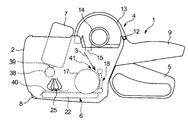
- FIG. 4 is a schematic side view of the portable boardless label printing and pasting machine 1
- FIG. 5 is a schematic side view of the state in which one side plate 2 is removed.
- a portable mountless label printing and pasting machine 1 includes a pair of left and right (front and back) side plates 2, a paper holder 4 for a label 3 without a mount (label continuous body), an operation lever 5, a platen unit 6, and a printer 7. And an affixing roller 8. *
- the pair of left and right side plates 2 are integrally formed with a grip 9 that can be gripped by the operator, and the operation lever 5 can be rotated around the lever shaft 10 (FIG. 5).
- an arbitrary biasing member for example, a coil spring 11 is provided between the operation lever 5 and the grip 9 so that the operation lever 5 is always on the grip 9 as shown in FIG. When released) Can be energized in a separated state.
- the operator grips the grip 9 and the operation lever 5 against the urging force of the coil spring 11 to drive the platen unit 6 and the printer 7 in the portable baseless label printing and sticking machine 1, and After releasing the holding operation, an operation of attaching the non-mounting label 3 by the attaching roller 8 of the portable boardless label printing and attaching machine 1 is performed.
- the label 3 without mount is wound in a roll shape and held in the paper holder 4, and the label 3 without mount is fed out in the direction of the printer 7 by the platen unit 6 in accordance with the operation of the operation lever 5.
- the non-mounting label 3 is separated from the platen unit 6, and the non-mounting label 3 can be attached to an adherend (not shown) by the attaching roller 8.
- the non-mounting label 3 is formed with slits 3A for transfer at a predetermined pitch, and when the platen unit 6 is transferred, an arbitrary cutting / separating unit (not shown) removes the single sheet from the strip-less mounting label 3 Label piece 3B.
- the paper holder 4 includes a holder cover 13 having a semicircular arc cross section that can be opened and closed with respect to the side plate 2 around a holder shaft 12 provided on the upper surface of the side plate 2, and a label holding provided inside the holder cover 13. It has a shaft 14 and a hook 15 for fixing to the side plate 2, and the label holding shaft 14 can be loaded and held with the label 3 without roll mount.
- FIG. 6 is a longitudinal sectional view of the platen unit 6 in a state in which the label 3 without the mount is loaded.
- the platen unit 6 transfers the label 3 without the mount fed from the paper holder 4 to the upper surface thereof.
- the platen frame 16, the transfer roller 17, and the pressing element 18 are included. *
- the platen frame 16 can be rotated around a platen opening / closing shaft 19 (FIG. 5) provided on the side plate 2, and the entire platen unit 6 can be opened and closed with respect to the side plate 2, so that the label 3 without the mount can be inserted and loaded.
- the platen frame 16 includes a drive gear 20 and a driven gear 21, and a transfer endless belt 22 wound around the drive gear 20 and the driven gear 21.
- the drive gear 20 is a roller gear of the transfer roller 17. 23 is engaged.
- the endless belt 22 for transfer can further transfer the label 3 without the mount, which is transferred by the transfer roller 17, and the surface thereof is contact-transferred with the back surface (glue surface) of the label 3 without the mount, so that it is non-adhesive
- This is composed of a silicone or fluorine-based rubber material having specific physical properties, or a release agent or the like is applied.
- the transfer endless belt 22 incorporated in the platen unit 6 also serves as a cradle (platen) for the stamping operation to the label 3 without the mount by the printer 7 and faces the printer 7 inwardly.
- a pressure receiving plate 22A (FIG. 6) is arranged.
- a pair of engagement / disengagement rollers 24 are formed on the left and right sides of the front end of the platen frame 16 so as to be linked to an opening / closing knob 25 (FIG. 4) provided on the side plate 2 and around a knob shaft 26 (FIG. 5).
- the engaging / disengaging recess 27A of the opening / closing engagement / disengagement piece 27 that is pivotable is capable of engaging / disengaging.
- an arbitrary spring material (not shown) is provided on the knob shaft 26 to bias the opening / closing engagement / disengagement piece 27 in a direction to engage with the engagement / disengagement roller 24.
- the opening / closing knob 25 operates the opening / closing engagement / disengagement piece 27 to be engaged / disengaged with the engagement / disengagement roller 24 so that the platen unit 6 and the opening / closing engagement / disconnection piece 27 can be engaged / disengaged with each other.
- the transfer roller 17 is rotatable around a roller shaft 28 provided on the platen frame 16 at a predetermined pitch in the transfer direction.
- a transfer rotation claw 30 is attached to a connecting arm 29 (FIG. 4) extending to the lower part of the lever shaft 10 of the operation lever 5 so as to be able to reciprocate, and the transfer rotation claw 30 is a side surface of the roller gear 23 in the transfer roller 17.
- Each of the plurality of transfer protrusions 31 provided radially can be engaged and disengaged.
- the transfer roller 17 is rotated by a predetermined pitch around the roller shaft 28 via the connecting arm 29, the transfer rotation claw 30, the roller gear 23, and the like.
- the mountless label 3 can be transferred, and the transfer endless belt 22 can be rotated by the coupling engagement between the roller gear 23 of the transfer roller 17 and the drive gear 20 to transfer the mountless label 3 to the upper surface thereof.
- a transfer claw (not shown) is formed on the transfer roller 17 at a predetermined pitch in the circumferential direction so that the transfer claw can be engaged with and disengaged from the transfer slit 3A of the label 3 without mount.
- the operation lever 5 has a bifurcated yoke portion 5A on the tip side, and a printer 7 (FIG. 4) is attached to the yoke portion 5A.
- the pressing element 18 is for pressing the non-mounting label 3 against the transfer roller 17, and is hung between the element frame 32, two pairs of upper and lower, left and right backup rollers 33, and the backup roller 33, and is located in the center. It has a ring 34 and a pair of left and right leaf springs 35. The pair of left and right leaf springs 35 function as a biasing member that separates the transfer roller 17 and the pressing element 18 from each other when the platen unit 6 is detached from the opening / closing engagement piece 27 (FIG. 5). The transfer roller 17 is separated from the gap, and a gap 36 (FIG. 5) that allows the non-mounting label 3 to be inserted can be formed therebetween.
- the platen frame 16 can be fixed to the side plate 2 against the urging force of the leaf spring 35 by the engagement of the engagement / disengagement roller 24 and the engagement / disengagement piece 27 for opening and closing.
- the element frame 32 can be rotated with respect to the platen frame 16 around an element shaft 37 (FIG. 5) provided on the outer wall surface of the platen frame 16.
- the platen frame 16 can be opened and closed relatively.
- the backup roller 33 and the backup ring 34 are made of non-adhesive silicone or fluorine rubber, or have a release agent.
- the label 3 having no mount can be pressed against the transfer roller 17 side.
- the backup roller 33 and the backup ring 34 are in line contact with the glue surface of the non-mounting label 3, the adhesive force with the glue surface can be reduced as much as possible, and pressing with predetermined spring elasticity is possible. is there.
- the backup roller 33 feeds the non-mounting label 3 onto the transfer endless belt 22 by the rotation of the transfer roller 17 while sandwiching the non-mounting label 3 between the transfer roller 17 and the pressing element 18.
- the leaf spring 35 is attached to the back surface of the element frame 32 opposite to the transfer roller 17 and abuts against the lever shaft 11 portion of the operation lever 5 so that the entire platen frame 16 (platen unit 6) is pressed against the pressing element 18. On the other hand, it is always biased in the opening direction (FIG. 5). *
- the printer 7 is attached to the tip end side of the bifurcated yoke portion 5A of the operation lever 5, and a plurality of type 39 (FIG. 4, FIG. 4) selected on one line of the printer 7 by the ink roller 38 (FIG. 4). Ink is applied to FIG. 7), and predetermined information is printed on the non-mounting label 3 (label piece 3B) transferred to the upper surface of the transfer endless belt 22 in the platen unit 6. *
- a pair of left and right label guide pieces 40 are provided above it, and both left and right edges of the mountless label 3 are pressed against the transfer endless belt 22 (platen) side. This can be guided, and printing by the printer 7 can be performed on the non-mounting label 3 (label piece 3B) located between the label guide pieces 40.
- a transfer path 41 is formed from the sheet holder 4 through the side plate 2 to the platen unit 6 (transfer roller 17 and pressing element 18) and further to the label guide piece 40. ing. *
- the sticking roller 8 is located at the lower end of the front end of the side plate 2, and the label piece 3 ⁇ / b> B peeled off from the endless belt 22 for transfer at the tip end of the endless belt 22 for transfer in the platen unit 6
- the label piece 3B by the pasting roller 8 is pasted on the body to be pasted. That is, the affixing roller 8 is located at the end of the side plate 2 (the left end lower end in FIG. 4), and a part of the circumferential portion is exposed to the outside of the side plate 2.
- the label piece 3B that has been transferred to the outside of the side plate 2 through the platen unit 6 and its transfer endless belt 22 so as to be discharged is rotated by striking the sticking roller 8 against the sticking object, thereby sticking the sticking object. It can be pasted on the body.
- FIG. 7 is a schematic front view of the printer 7, the transfer endless belt 22 and the label guide piece 40 as viewed from the downstream side (the sticking roller 8 side), in which the operation lever 5 and the grip 9 are gripped.
- the printer 7 is lowered toward the transfer endless belt 22, and the type 39 of the printer 7 is pressed against the non-mounting label 3 (label piece 3 ⁇ / b> B) on the transfer endless belt 22 to perform printing.
- the label guide piece 40 is guided along the transfer path 41 between the pair of left and right side plates 2 while pressing the left and right edge portions 3C of the label continuum 3 from the upper surface side over a predetermined width. Therefore, the printer 7 performs printing on the label piece 3B of the label continuum 3 between the label guide pieces 40. . Therefore, the label 3 without the mount has a problem that it is practically impossible to perform printing in the area near the label guide piece 40, that is, the area of the left and right edges 3C. *
- the printer 7 may be designed to be large by increasing the width between the pair of left and right side plates 2, but it is unavoidable to increase the size of the portable baseless label printing applicator 1. There is a problem.
- the printable area or the printable area by the label guide piece 40 is not limited to the label 3 without the mount as the label continuous body, but also in the case of the label continuous body generally having a mount and a label piece. It is the same that there are regulations.
- the present invention has been considered in view of the above problems, and provides a label guide device and a label guide method for a portable label printing and pasting machine capable of printing more information between a pair of left and right side plates. Is an issue. *
- this invention makes it a subject to provide the label guide apparatus and label guide method of the portable label printing sticking machine which can increase the number of digits of the character of a printer.
- this invention makes it a subject to provide the label guide apparatus and label guide method of the portable label printing sticking machine which can enlarge the character of a printer more.
- this invention makes it a subject to provide the label guide apparatus and label guide method of the portable label printing sticking machine which can print also on the both right and left edge parts covered with the label guide piece.
- this invention makes it a subject to provide the label guide apparatus and label guide method of a portable label printing sticking machine which can raise the added value as a label continuous body (label piece) which displays information.
- the present invention focuses on the fact that a label guide piece for holding and guiding a label without a mount and other label continuum is retracted in the direction of the side plate during a printing operation.
- the side plate a label guide piece for guiding the left and right edges of the label continuum from the upper surface side along the transfer path between the side plates, and the label continuum in a region different from the label guide piece.
- a label guide device for a portable label printing and pasting machine that has a printer for printing on a label piece, and that allows the label piece of the label continuous body to be attached to an adherend.
- a support portion provided along the transfer path, an elastic portion that can be elastically deformed in a direction toward and away from the support portion, and a tip portion of the elastic portion.
- a guide portion capable of pressing the label continuum, and when the printer performs printing on the label continuum, the abutting against the elastic portion of the label guide piece, the guide portion is It is a label guide device of a portable label printing and pasting machine characterized in that it can be displaced in the direction of the side plate.
- a pair of left and right side plates a label guide piece for guiding the left and right edges of the label continuous body from the upper surface side along a transfer path between the side plates, and the label guide piece.
- a label guide method for a portable label printing and sticking machine that can attach the label piece of the label continuous body to an adherend.
- the label guide piece includes a support portion provided along the transfer path, an elastic portion that can be elastically deformed in a direction toward and away from the support portion, and the label continuous at the tip of the elastic portion.
- a guide portion capable of pressing the body, and the guide portion pushes the left and right edge portions of the label continuous body from the upper surface side when the label continuous body is transferred in the transfer path.
- the label When the printer performs printing on the label continuum, the label abuts against the elastic portion of the label guide piece and pushes the guide portion in the direction of the side plate, and the label by the printer Portable label printing characterized in that printing on a continuous body is possible, and when the printing on the label continuous body by the printer is finished, the guide unit returns to the original position where the label continuous body can be guided. It is a label guide method of a pasting machine. *
- a pair of the label guide pieces may be arranged on the left and right sides of the transfer path.
- the elastic part may be disposed obliquely from the support part toward the label continuous body in the transfer path.
- a part of the elastic portion may be located in a locus of the printer toward the label continuum in the transfer path.
- the guide portion may extend in the length direction of the label continuous body along the transfer path. *
- the guide portion may be formed in the elastic portion so as to move substantially in parallel in the width direction of the label continuous body.
- the support part may be fixed to the left and right of the platen.
- the label continuum is not limited to the non-mounting label 3 described with reference to FIGS. 4 to 7, but may be a general label continuum composed of a mount and a label piece.
- the present invention can also be applied to a portable label printing and pasting machine.
- the label guide pieces 40 are movable to the both edges in the width direction of the label 3 without the mount according to the printing operation of the printer 7. Therefore, it is possible to perform printing with the type 39 of the printer 7 in both end regions that have been conventionally covered by the label guide piece 40, and secure the necessary number of digits or increase the size of the type 39 itself. Such a design is possible.
- the printer contacts the elastic portion of the label guide piece when printing on the label continuous body, and the guide portion is directed toward the side plate. Since it is possible to displace, it is possible to expand the printing area at both the left and right edges of the continuous label body, which has been impossible to print. Therefore, it is possible to design such as increasing the number of characters in the printer or expanding the size of the characters.
- the printer when the printer performs printing on the label continuous body, it abuts against the elastic portion of the label guide piece and pushes the guide portion toward the side plate.
- the guide unit is returned to the original position where the label continuum can be guided, so that the label continuum can be transferred and printed while ensuring a larger printing area. In both processes, the label continuum can be stably guided.
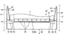
- FIG. 7 The same printer 7, transfer endless belt 22, and label guide device 51 (FIG. 7) when the portable label printing and pasting machine 50 is adopted as the portable label printing and pasting machine according to the embodiment of the present invention.
- It is the schematic front view which looked at the part of the label guide piece 52) from the downstream (the sticking roller 8 side). It is a schematic front view at the time of printing operation.
- 2 is a perspective view of a label guide piece 52 in the label guide device 51.
- FIG. It is a schematic side view of the conventional portable mountless label printing and pasting machine 1. It is a schematic side view of the state which removed the one side plate 2 same as the above.
- FIG. 6 is a longitudinal sectional view of the platen unit 6 in a state where the label 3 without mount is loaded. It is the schematic front view which looked at the part of the printer 7, the endless belt 22 for transfer, and the label guide piece 40 from the downstream side (the sticking roller 8 side).
- the label guide piece is withdrawn from the label continuous body along with the printing, and the printing is finished.
- the guide part of the label guide piece also returns to the original position, and the label guide device and label guide method of the portable label printing and pasting machine that can perform normal guide of the label continuum are realized. did.
- FIG. 1 shows a printer 7, a transfer endless belt 22, and a label guide device 51 (label guide) similar to those in FIG. 7 when a portable board-less label printing / pasting machine 50 is adopted as a portable label printing / pasting machine.
- 2 is a schematic front view of the portion 52) viewed from the downstream side (the sticking roller 8 side).
- FIG. 2 is a schematic front view of the printing operation
- FIG. 3 is a label guide piece in the label guide device 51.
- the label guide piece 52 is composed of a metal material or a synthetic resin material having a predetermined rigidity and elasticity, and a pair thereof is provided on the left and right sides of the transfer path 41, and includes a support portion 53, an elastic portion 54, And a guide portion 55.
- the support portion 53 is plate-shaped, and has a fixing fixing through hole 56 formed in the base portion thereof, and is provided on the left and right sides of the platen unit 6 (platen) for transferring the non-mounting label 3 (label continuous body).
- the printer 7 is fixed at a lower position in FIG. *
- the elastic portion 54 can be elastically deformed in the direction of approaching and detaching from the support portion 53, and in particular, as shown in FIG. 1, from the support portion 53 toward the lower side of the printer 7 in the transfer path 41 ( The pair is positioned obliquely away from the side plate 2 (in the direction of the non-mounting label 3). In other words, a part of the elastic portion 54 is positioned in the trajectory of the printer 7 that moves downward toward the label 3 without the mount in the transfer path 41.
- the lowermost end portions 7 ⁇ / b> A abut against the elastic portions 54 of the label guide pieces 52 so that the guide portions 55 can be pushed in the direction of the side plate 2.
- the guide portion 55 can press the mountless label 3 at the free end (tip portion) of the elastic portion 54, and extends in the length direction of the mountless label 3 along the transfer path 41.
- the upstream end portion 55A of the guide portion 55 is formed to warp upward, and the label 3 without the mount is guided to the transfer path 41 between the platen unit 6 (transfer endless belt 22).
- the downstream end portion 55B is formed to be bent downward so that the single-leaf label piece 3B can be guided to the lower portion of the sticking roller 8.
- the guide portion 55 is formed in the elastic portion 54 so as to move substantially in the width direction of the non-mounting label 3 in accordance with the printing operation and the releasing operation by the printer 7. *
- the printer 7 is positioned above the label guide piece 52, and an operator of the portable mountless label printing and pasting machine 50 holds the operation lever 5 and the grip 9, and the printer 7 moves to the transfer path 41 (platen unit). 6 endless belt 22 in the direction of 6), lowermost end portions 7A come into contact with elastic portion 54, and elastically deform it while moving toward support portion 53 (outward in the width direction of label 3 without mount). The side plate 2 side) is retracted so that the elastic portion 54 approaches.
- the guide portion 55 integral with the elastic portion 54 is retracted outward, and the area near the left and right edge portions 3C of the label 3 without the mount is printed. 7 type 39 is opened so that it can be stamped.
- the left and right edges 3C of the label 3 without the mount may be disengaged from the guide portion 55 of the label guide piece 52. It may be in a state of being.
- the guide portion 55 By forming the guide portion 55 so as to slightly warp upward from the plane of the non-mounting label 3, the guide portion 55 that reciprocates substantially in parallel with the printing operation by the printer 7 and the releasing operation thereof is provided. It is possible to stably realize a posture for pressing the label 3 without mount and a release posture thereof.
- the width W2 (FIG. 1) of the type 39 of the printer 7 can be formed larger than the width W1 (FIG. 7) of the conventional type 39.
- printing by the type 39 is performed. It can be displayed larger.
- the printable area can be expanded in the width direction of the label continuum (the label 3 without the mount), so that the type 39 of the printer 7 can be increased as necessary.
- the number of digits can be increased.
Landscapes
- Labeling Devices (AREA)
- Handling Of Continuous Sheets Of Paper (AREA)
Abstract
本発明は、ラベル連続体(3)を押さえてガイドするラベルガイド片(52)を、印字動作時に側板(2)の方向に退避させるようにすることに着目したもので、ラベルガイド片(52)は、移送路(41)に沿って設けた支持部(53)と、支持部(53)に対して接近および離脱する方向に弾性変形可能な弾性部(54)と、弾性部(54)の先端部においてラベル連続体(3)を押さえ付け可能なガイド部(55)と、を有するとともに、印字器(7)が、ラベル連続体(3)に印字を行う際にラベルガイド片(52)の弾性部(54)に当接して、ガイド部(55)を側板(2)方向に押しのけ可能とすることを特徴とする。
Description
本発明は携帯式ラベル印字貼付け機のラベルガイド装置およびラベルガイド方法にかかるもので、とくにラベル連続体の左右両縁部を案内するための携帯式ラベル印字貼付け機のラベルガイド装置およびラベルガイド方法に関するものである。
従来から、単葉のラベル片を複数枚有するラベル連続体を移送するとともに印字器により、ラベル片に印字を行って商品その他任意の被貼付け体に貼り付けるための携帯式ラベル印字貼付け機においては、印字器との間にラベル連続体が位置することになるプラテンの上面部分においてラベル連続体を案内するためのラベルガイド片を設けている。 従来の携帯式ラベル印字貼付け機として台紙なしラベル用の携帯式ラベル印字貼付け機(携帯式台紙なしラベル印字貼付け機1)を例にとって図4ないし図7にもとづき概説する。
図4は、携帯式台紙なしラベル印字貼付け機1の概略側面図、図5は、同、一方の側板2を取り除いた状態の概略側面図である。 携帯式台紙なしラベル印字貼付け機1は、左右(紙面表裏)一対の側板2と、台紙なしラベル3(ラベル連続体)の用紙ホルダー4と、操作レバー5と、プラテンユニット6と、印字器7と、貼付けローラー8と、を有する。
左右一対の側板2は、操作者が握持可能なグリップ9を一体に形成するとともに、このグリップ9に対してレバー軸10(図5)のまわりに操作レバー5を回動操作可能としている。 なお、操作レバー5とグリップ9との間には、任意の付勢部材、たとえばコイルスプリング11を設けて、操作レバー5をグリップ9に対して、図4に示すような常時(操作レバー5の解放時)離反状態に付勢可能としている。 操作者は、コイルスプリング11の付勢力に抗してグリップ9および操作レバー5を握持して携帯式台紙なしラベル印字貼付け機1内のプラテンユニット6および印字器7を駆動するとともに、この握持操作を解放後、携帯式台紙なしラベル印字貼付け機1の貼付けローラー8による台紙なしラベル3の貼付け操作を行うことになる。
台紙なしラベル3は、これをロール状に巻いて用紙ホルダー4に保持するとともに、操作レバー5の操作にともなって、プラテンユニット6により印字器7方向に台紙なしラベル3を帯状に繰り出し、プラテンユニット6の先端部でプラテンユニット6から台紙なしラベル3を分離し、貼付けローラー8により台紙なしラベル3を被貼付け体(図示せず)に貼り付け可能とする。ただし、台紙なしラベル3には所定ピッチで移送用スリット3Aなどを形成し、プラテンユニット6上を移送する際に、任意の切断分離ユニット(図示せず)により、帯状の台紙なしラベル3から単葉のラベル片3Bとすることができる。
用紙ホルダー4は、側板2の上面に設けたホルダー軸12のまわりに側板2に対して開閉回動可能とした断面半円弧状のホルダーカバー13と、このホルダーカバー13の内部に設けたラベル保持軸14と、側板2への固定用フック15と、を有し、ラベル保持軸14にロール状の台紙なしラベル3を装填保持可能としてある。
図6は、台紙なしラベル3を装填した状態のプラテンユニット6部分の縦断面図であって、プラテンユニット6は、用紙ホルダー4から帯状に繰り出された台紙なしラベル3をその上面に移送するもので、プラテンフレーム16と、移送ローラー17と、押付けエレメント18と、を有している。
プラテンフレーム16は、側板2に設けたプラテン開閉軸19(図5)のまわりにこれを回動可能とし、側板2に対してプラテンユニット6全体を開閉し、台紙なしラベル3の挿通装填を可能とする。 プラテンフレーム16は、駆動ギア20および従動ギア21と、これら駆動ギア20および従動ギア21のまわりに掛け回した移送用無端ベルト22と、を備えており、駆動ギア20が移送ローラー17のローラーギア23に係合する。 移送用無端ベルト22は、移送ローラー17により移送されてくる台紙なしラベル3をさらに移送可能であって、その表面は、台紙なしラベル3の裏面(糊面)が接触移送されるため、非粘着性の物性を有するシリコーンあるいはフッ素系のゴム材からこれを構成するか、剥離剤などを塗布しておく。また、このプラテンユニット6に組み込まれた移送用無端ベルト22は、印字器7による台紙なしラベル3への押印動作の受け台(プラテン)ともなるもので、その内方において印字器7に対向する受圧用プレート22A(図6)を配置してある。 なお、プラテンフレーム16の先端側の左右には、一対の係脱ローラー24を突出形成し、側板2に設けた開閉用つまみ25(図4)に連動してつまみ軸26(図5)のまわりに回動する開閉用係脱片27の係脱用凹部27Aに係脱可能としてある。ただし、つまみ軸26には任意のバネ材(図示せず)を設けて、開閉用係脱片27が係脱ローラー24に係合する方向にこれを付勢している。 すなわち、開閉用つまみ25は、係脱ローラー24に係脱する開閉用係脱片27を操作して、プラテンユニット6と開閉用係脱片27とを互いに係脱可能としている。
移送ローラー17は、プラテンフレーム16に設けたローラー軸28のまわりに移送方向に所定ピッチでこれを回転可能としてある。 操作レバー5のレバー軸10の下方部に延びる連結アーム29(図4)に移送回動用爪30を往復動可能に取り付けてあり、この移送回動用爪30が移送ローラー17におけるローラーギア23の側面に放射状に設けた複数個の移送用突起31それぞれに係脱可能である。
かくして、操作レバー5をグリップ9とともに握持および解放することにより、連結アーム29、移送回動用爪30およびローラーギア23などを介してローラー軸28のまわりに移送ローラー17を所定ピッチだけ回転して台紙なしラベル3を移送可能とするとともに、移送ローラー17のローラーギア23と駆動ギア20との連結係合により移送用無端ベルト22を回転させて台紙なしラベル3をその上面に移送可能である。
さらに移送ローラー17に所定ピッチでその円周方向に移送用爪(図示せず)を突出形成し、この移送用爪を台紙なしラベル3の移送用スリット3Aに係脱可能としている。 なお、操作レバー5には、その先端側に二股状のヨーク部5Aを有し、このヨーク部5Aに印字器7(図4)を取り付けている。
押付けエレメント18は、移送ローラー17に台紙なしラベル3を押し付けるためのものであり、エレメントフレーム32と、上下左右二対のバックアップローラー33と、バックアップローラー33の間に掛け回して中央に位置するバックアップリング34と、左右一対の板バネ35と、を有する。 左右一対の板バネ35は、プラテンユニット6が開閉用係脱片27(図5)から離脱したときに、移送ローラー17と押付けエレメント18とを互いに離反させる付勢部材として機能し、押付けエレメント18から移送ローラー17を離反させ、その間に台紙なしラベル3を挿通可能とする間隙36(図5)を形成可能とする。 ただし、プラテンフレーム16は、係脱ローラー24と開閉用係脱片27との係合により、板バネ35の付勢力に抗して側板2にこれを固定可能としている。 なお、エレメントフレーム32は、プラテンフレーム16の外壁面に設けたエレメント軸37(図5)のまわりにプラテンフレーム16に対してこれを回動可能としてあり、プラテンユニット6において押付けエレメント18に対してプラテンフレーム16を相対的に開閉可能としている。
バックアップローラー33およびバックアップリング34は、台紙なしラベル3の裏面(糊面)が接触移送されるため、非粘着性の物性を有するシリコーンあるいはフッ素系のゴム材からこれを構成するか、剥離剤などを塗布しておくもので、台紙なしラベル3を移送ローラー17側に押し付け可能である。 また、バックアップローラー33およびバックアップリング34は、台紙なしラベル3の糊面に線接触するため、糊面との粘着力を極力小さくすることができるとともに、所定のバネ弾性をもった押付けが可能である。 バックアップローラー33は、移送ローラー17と押付けエレメント18との間に台紙なしラベル3を挟持しつつ、移送ローラー17の回転によって台紙なしラベル3を移送用無端ベルト22上に送り出す。
板バネ35は、移送ローラー17とは反対側のエレメントフレーム32の背面にこれを取り付け、操作レバー5のレバー軸11部分に当接して、プラテンフレーム16(プラテンユニット6)全体を押付けエレメント18に対して常時開放方向(図5)に付勢する。
印字器7は、操作レバー5における二股状のヨーク部5Aの先端部側にこれを取り付け、インキローラー38(図4)により印字器7の一列上に選択した複数個の活字39(図4、図7)にインキを塗布し、プラテンユニット6における移送用無端ベルト22の上面に移送されてきた台紙なしラベル3(ラベル片3B)に所定の情報を印字する。
なお、移送用無端ベルト22の下流領域には、その上方に左右一対のラベルガイド片40を設けて、台紙なしラベル3の左右両縁部を移送用無端ベルト22(プラテン)側に押さえ付けてこれを案内可能としてあり、ラベルガイド片40の間に位置する台紙なしラベル3(ラベル片3B)に印字器7による印字を可能とする。 かくして、とくに図4に示すように、用紙ホルダー4の部分から側板2内をとおり、プラテンユニット6(移送ローラー17、押付けエレメント18)さらにはラベルガイド片40の部分に至る移送路41を形成している。
貼付けローラー8は、側板2の先端下方部に位置し、プラテンユニット6における移送用無端ベルト22の先端部分で移送用無端ベルト22から剥離されたラベル片3Bを、携帯式台紙なしラベル貼付け機1全体の貼付け操作にともなって、貼付けローラー8によるラベル片3Bを被貼付け体に貼り付ける。 すなわち、貼付けローラー8は、側板2の端部(図4中、左端下方端部)に位置するとともに、その円周部の一部が側板2の外部に露出しており、側板2の外部に排出するようにプラテンユニット6およびその移送用無端ベルト22を通って側板2の外部に移送されてきたラベル片3Bを、貼付けローラー8を被貼付け体に打ち付けるようにして回転させることにより、被貼付け体に貼り付け可能とする。
図7は、印字器7、移送用無端ベルト22およびラベルガイド片40の部分を下流側(貼付けローラー8側)から見た概略正面図であって、前記操作レバー5およびグリップ9が握持されて印字器7が移送用無端ベルト22方向に下降し、印字器7の活字39が移送用無端ベルト22上の台紙なしラベル3(ラベル片3B)に押し付けられて印字を行った状態を示している。
ラベルガイド片40は、左右一対の側板2の間における移送路41に沿ってラベル連続体3の左右両縁部3Cを所定の幅にわたって上面側から押さえつつ案内することにより、移送用無端ベルト22から台紙なしラベル3が上下左右方向に脱落することを防止するようにしているため、印字器7は、このラベルガイド片40の間においてラベル連続体3のラベル片3Bに印字を行うことになる。 したがって、台紙なしラベル3には、ラベルガイド片40に押さえ付けられるその付近の領域すなわち、その左右両縁部3Cの領域部分には印字を行うことは事実上不可能であるという問題がある。
しかしながら、ラベル片3Bの印字可能な領域ないし面積をより大きく確保すること、さらには印字される情報の密度を上げてその付加価値を向上させることが、省資源の観点からも要請されているにもかかわらず、印字器7の活字39の幅W1(印字幅)をできるだけ大きく取って活字39による印字の文字をより大きくする構成、あるいは印字(活字
39)の桁数を増やす構成が困難であるという問題がある。 上記諸要請に対しては、左右一対の側板2の間の幅を大きくして印字器7を大きく設計すればよいが、携帯式台紙なしラベル印字貼付け機1の大型化を避けられないという別の問題がある。
39)の桁数を増やす構成が困難であるという問題がある。 上記諸要請に対しては、左右一対の側板2の間の幅を大きくして印字器7を大きく設計すればよいが、携帯式台紙なしラベル印字貼付け機1の大型化を避けられないという別の問題がある。
上述のような問題は、ラベル連続体として台紙なしラベル3以外にも、一般的に台紙およびラベル片を有する構成のラベル連続体の場合にも、ラベルガイド片40による印字可能領域ないし印字可能面積の規制があるということは同様である。
本発明は以上のような諸問題にかんがみなされたもので、左右一対の側板の間において、より多くの情報を印字可能とする携帯式ラベル印字貼付け機のラベルガイド装置およびラベルガイド方法を提供することを課題とする。
また本発明は、印字器の活字の桁数を増やすことができる携帯式ラベル印字貼付け機のラベルガイド装置およびラベルガイド方法を提供することを課題とする。
また本発明は、印字器の活字をより大きくすることができる携帯式ラベル印字貼付け機のラベルガイド装置およびラベルガイド方法を提供することを課題とする。
また本発明は、ラベルガイド片により覆われていた左右両縁部にも印字を可能とする携帯式ラベル印字貼付け機のラベルガイド装置およびラベルガイド方法を提供することを課題とする。
また本発明は、情報を表示するラベル連続体(ラベル片)としての付加価値を高めることができる携帯式ラベル印字貼付け機のラベルガイド装置およびラベルガイド方法を提供することを課題とする。
すなわち本発明は、台紙なしラベルその他のラベル連続体を押さえてガイドするラベルガイド片を、印字動作時に側板の方向に退避させるようにすることに着目したもので、第一の発明は、左右一対の側板と、この側板の間における移送路に沿ってラベル連続体の左右両縁部を上面側から押さえつつ案内するためのラベルガイド片と、このラベルガイド片とは異なる領域において上記ラベル連続体のラベル片に印字を行う印字器と、を有するとともに、上記ラベル連続体の上記ラベル片を被貼付け体に貼り付け可能とする携帯式ラベル印字貼付け機のラベルガイド装置であって、上記ラベルガイド片は、上記移送路に沿って設けた支持部と、この支持部に対して接近および離脱する方向に弾性変形可能な弾性部と、この弾性部の先端部において上記ラベル連続体を押さえ付け可能なガイド部と、を有するとともに、上記印字器が、上記ラベル連続体に印字を行う際に上記ラベルガイド片の上記弾性部に当接して、上記ガイド部を上記側板方向に押しのけ可能とすることを特徴とする携帯式ラベル印字貼付け機のラベルガイド装置である。
第二の発明は、左右一対の側板と、この側板の間における移送路に沿ってラベル連続体の左右両縁部を上面側から押さえつつ案内するためのラベルガイド片と、このラベルガイド片の間において上記ラベル連続体のラベル片に印字を行う印字器と、を有するとともに、上記ラベル連続体の上記ラベル片を被貼付け体に貼り付け可能とする携帯式ラベル印字貼付け機のラベルガイド方法であって、上記ラベルガイド片は、上記移送路に沿って設けた支持部と、この支持部に対して接近および離脱する方向に弾性変形可能な弾性部と、この弾性部の先端部において上記ラベル連続体を押さえ付け可能なガイド部と、を有し、このガイド部は、上記ラベル連続体の上記移送路における移送時には、上記ラベル連続体の上記左右両縁部を上面側から押さえ付け可能であるとともに、上記印字器が上記ラベル連続体に印字を行う際に上記ラベルガイド片の上記弾性部に当接して上記ガイド部を上記側板方向に押しのけて、上記印字器による上記ラベル連続体への印字を可能とし、上記印字器による上記ラベル連続体への印字終了の際に上記ガイド部が上記ラベル連続体を案内可能な元位置に復帰することを特徴とする携帯式ラベル印字貼付け機のラベルガイド方法である。
上記ラベルガイド片は、上記移送路の左右にその一対を配置していることができる。
上記弾性部は、上記支持部から上記移送路における上記ラベル連続体の方向に向かって斜めにこれを配置していることができる。
上記弾性部は、上記移送路において上記ラベル連続体に向かう上記印字器の軌跡内にその一部を位置させていることができる。
上記ガイド部は、上記移送路に沿って上記ラベル連続体の長さ方向に延びていることができる。
上記ガイド部は、上記ラベル連続体の幅方向においてほぼ平行移動するように上記弾性部にこれを形成していることができる。
上記ガイド部が上記側板方向に押しのけられた状態で、上記印字器による上記ラベル連続体への印字を可能とすることができる。
上記ラベル連続体をその上面に移送するとともに上記印字器による上記ラベル連続体への印字を行うためのプラテンを有するとともに、上記支持部は、このプラテンの左右にこれを固定してあることができる。
上記ラベル連続体としては、図4ないし図7にもとづき説明した台紙なしラベル3に限らず、台紙およびラベル片からなる一般的なラベル連続体であってもよく、このようなラベル連続体を装填する携帯式ラベル印字貼付け機にも本発明を適用可能である。
本発明による携帯式ラベル印字貼付け機のラベルガイド装置およびラベルガイド方法においては、印字器7の印字動作にともなってラベルガイド片40が台紙なしラベル3の幅方向両縁部側に可動するようにしたので、従来ラベルガイド片40により覆われていた両端部の領域にも印字器7の活字39による印字が可能となり、必要な桁数を確保したり、あるいは活字39自体の大きさを大きくするような設計が可能となる。
とくに第一の発明の携帯式ラベル印字貼付け機のラベルガイド装置によれば、印字器が、ラベル連続体に印字を行う際にラベルガイド片の弾性部に当接して、ガイド部を側板方向に押しのけ可能としたので、従来は印字不可能であったラベル連続体の左右両縁部にも印字領域を拡大することができる。したがって、印字器における活字の桁数を増やしたり、活字の大きさを拡大するなどの設計が可能となる。
とくに第二の発明の携帯式ラベル印字貼付け機のラベルガイド方法によれば、印字器がラベル連続体に印字を行う際にラベルガイド片の弾性部に当接してガイド部を側板方向に押しのけるとともに、印字器によるラベル連続体への印字終了の際にガイド部がラベル連続体を案内可能な元位置に復帰するようにしたので、印字領域をより大きく確保しつつ、ラベル連続体の移送および印字の工程においてともにラベル連続体を安定して案内することができる。
本発明は、印字動作を行う印字器がラベルガイド片を押しのけることができるような弾性部およびガイド部を形成したので、印字にともないラベルガイド片がラベル連続体から退避し、印字が終了して印字器が元位置に戻ると、ラベルガイド片のガイド部も元位置に復帰してラベル連続体の通常のガイドを行うことができる携帯式ラベル印字貼付け機のラベルガイド装置およびラベルガイド方法を実現した。
つぎに本発明の実施例による携帯式ラベル印字貼付け機のラベルガイド装置およびラベルガイド方法を図1ないし図3にもとづき説明する。ただし、図4ないし図7と同様の部分には同一符号を付し、その詳述はこれを省略する。 図1は、携帯式ラベル印字貼付け機として、携帯式台紙なしラベル印字貼付け機50を採用した場合の、図7と同様の、印字器7、移送用無端ベルト22およびラベルガイド装置51(ラベルガイド片52)の部分を下流側(貼付けローラー8側)から見た概略正面図であって、図2は、同、印字動作時の概略正面図、図3は、ラベルガイド装置51におけるラベルガイド片52の斜視図である。
ラベルガイド片52は、所定の剛性および弾性を有する金属材料あるいは合成樹脂材料からこれを構成するもので、移送路41の左右にその一対を設けており、支持部53と、弾性部54と、ガイド部55と、をそれぞれ有する。
支持部53は、板状であって、その基部に取付け固定用貫通孔56を形成してあるとともに、台紙なしラベル3(ラベル連続体)を移送するためのプラテンユニット6(プラテン)の左右に移送路41に沿って、移送路41の面に垂直に起立した状態で印字器7の図1中、下方部に位置してこれを固定してある。
弾性部54は、この支持部53に対して接近および離脱する方向に弾性変形可能であって、とくに図1に示すように、支持部53から移送路41における印字器7の下方に向かって(台紙なしラベル3の方向に)側板2から離れる方向に斜め方向にその一対を位置させている。 換言すれば、弾性部54は、移送路41において台紙なしラベル3に向かって下降動作する印字器7の軌跡内にその一部を位置させている。 かくして、印字器7が台紙なしラベル3に印字を行う際にその最下方両端部7Aがラベルガイド片52の弾性部54に当接してガイド部55を側板2方向に押しのけ可能とする。
ガイド部55は、この弾性部54の自由端部(先端部)において台紙なしラベル3を押さえ付け可能であって、移送路41に沿って台紙なしラベル3の長さ方向に延びている。とくに図3に示すように、ガイド部55の上流側端部55Aを上方側に反って形成して台紙なしラベル3をプラテンユニット6(移送用無端ベルト22)との間の移送路41に案内しやすくするとともに、その下流側端部55Bを下方側に折り曲げるように形成して単葉のラベル片3Bを貼付けローラー8の下方部に案内可能としている。 なお、印字機7による印字動作およびその解除動作にともなって、ガイド部55は、台紙なしラベル3の幅方向においてほぼ平行移動するように弾性部54にこれを形成している。
こうした構成の携帯式台紙なしラベル印字貼付け機50およびそのラベルガイド装置51において、とくに図1に示すように、操作レバー5およびグリップ9が解放されていて、印字動作が行われていない状態では、印字器7がラベルガイド片52の上方に位置しており、携帯式台紙なしラベル印字貼付け機50の作業者が操作レバー5およびグリップ9を握持して印字器7が移送路41(プラテンユニット6の移送用無端ベルト22)方向に下降してくると、その最下方両端部7Aが弾性部54に当接し、これを弾性変形させながら支持部53方向(台紙なしラベル3の幅方向外方の側板2側)に弾性部54が接近するように退避させる。
この弾性部54の退避動作にともなって、図2に示すように、弾性部54に一体のガイド部55が外方に退避し、台紙なしラベル3の左右両縁
部3C付近の領域を印字器7の活字39が押印可能に開放する。 この押印可能な状態においては、台紙なしラベル3の左右両縁部3Cがラベルガイド片52のガイド部55から外れてもかまわないし、必要であれば、従来より細長い領域にわたってガイド部55により押さえ付けられている状態であってもよい。 なお、ガイド部55を台紙なしラベル3の平面から上方にわずかに反らせるように形成しておくことにより、印字器7による印字動作およびその解除動作にともなってほぼ平行に往復動するガイド部55が台紙なしラベル3を押さえ付ける態勢およびその解除態勢を安定して実現するようにすることができる。
部3C付近の領域を印字器7の活字39が押印可能に開放する。 この押印可能な状態においては、台紙なしラベル3の左右両縁部3Cがラベルガイド片52のガイド部55から外れてもかまわないし、必要であれば、従来より細長い領域にわたってガイド部55により押さえ付けられている状態であってもよい。 なお、ガイド部55を台紙なしラベル3の平面から上方にわずかに反らせるように形成しておくことにより、印字器7による印字動作およびその解除動作にともなってほぼ平行に往復動するガイド部55が台紙なしラベル3を押さえ付ける態勢およびその解除態勢を安定して実現するようにすることができる。
かくして、印字器7の活字39の幅W2(図1)を従来の活字39の幅W1(図7)に比較してより大きく形成することが可能となり、図示の例では、活字39による印字をより大きく表示することができる。
操作レバー5およびグリップ9を開放すれば、印字器7が図1に示す上方位置に復帰するので、ラベルガイド片52は弾性部54の弾性によりガイド部55も台紙なしラベル3の左右両縁部3Cを押さえ付ける元位置に復帰し、移送ローラー17および移送用無端ベルト22などにより移送される台紙なしラベル3をガイドする態勢になる。
したがって、本発明によれば、印字可能領域をラベル連続体(台紙なしラベル3)の幅方向に拡大することができるので、必要に応じて、印字器7の活字39をより大きくしたり、その桁数を増やすことができる。
1 携帯式台紙なしラベル印字貼付け機(携帯式ラベル印字貼付け機、従来、図4) 2 側板 3 台紙なしラベル(ラベル連続体) 3A 台紙なしラベル3の移送用スリット 3B 台紙なしラベル3のラベル片 3C 台紙なしラベル3の左右両縁部(図1、図2、図7) 4 用紙ホルダー 5 操作レバー 6 プラテンユニット 7 印字器 7A 印字器7の最下方両端部(図1、図2) 8 貼付けローラー 9 グリップ10 レバー軸11 コイルスプリング12 ホルダー軸13 ホルダーカバー14 ラベル保持軸15 固定用フック16 プラテンフレーム17 移送ローラー18 押付けエレメント19 プラテン開閉軸20 駆動ギア21 従動ギア22 移送用無端ベルト(プラテン)22A 移送用無端ベルト22の受圧用プレート23 ローラーギア24 係脱ローラー25 開閉用つまみ26 つまみ軸27 開閉用係脱片27A 開閉用係脱片27の係脱用凹部28 ローラー軸29 連結アーム30 移送回動用爪31 移送用突起32 エレメントフレーム33 バックアップローラー34 バックアップリング35 板バネ36 間隙37 エレメント軸38 インキローラー39 印字器7の活字40 ラベルガイド片41 移送路50 携帯式台紙なしラベル印字貼付け機50(携帯式ラベル印字貼付け機)51 携帯式台紙なしラベル印字貼付け機50のラベルガイド装置(実施例、図1)52 ラベルガイド片53 ラベルガイド片52の支持部54 ラベルガイド片52の弾性部55 ラベルガイド片52のガイド部55A ガイド部55の上流側端部55B ガイド部55の下流側端部56 固定用貫通孔W1 印字器7の活字39の幅(従来、図7)W2 印字器7の活字39の幅(実施例、図1、W1<W2)
Claims (9)
- 左右一対の側板と、 この側板の間における移送路に沿ってラベル連続体の左右両縁部を上面側から押さえつつ案内するためのラベルガイド片と、 このラベルガイド片とは異なる領域において前記ラベル連続体のラベル片に印字を行う印字器と、を有するとともに、 前記ラベル連続体の前記ラベル片を被貼付け体に貼り付け可能とする携帯式ラベル印字貼付け機のラベルガイド装置であって、 前記ラベルガイド片は、 前記移送路に沿って設けた支持部と、 この支持部に対して接近および離脱する方向に弾性変形可能な弾性部と、 この弾性部の先端部において前記ラベル連続体を押さえ付け可能なガイド部と、を有するとともに、 前記印字器が、前記ラベル連続体に印字を行う際に前記ラベルガイド片の前記弾性部に当接して、前記ガイド部を前記側板方向に押しのけ可能とすることを特徴とする携帯式ラベル印字貼付け機のラベルガイド装置。
- 前記ラベルガイド片は、前記移送路の左右にその一対を配置していることを特徴とする請求項1記載の携帯式ラベル印字貼付け機のラベルガイド装置。
- 前記弾性部は、前記支持部から前記移送路における前記ラベル連続体の方向に向かって斜めにこれを配置していることを特徴とする請求項1または2記載の携帯式ラベル印字貼付け機のラベルガイド装置。
- 前記弾性部は、前記移送路において前記ラベル連続体に向かう前記印字器の軌跡内にその一部を位置させていることを特徴とする請求項1ないし3のいずれかに記載の携帯式ラベル印字貼付け機のラベルガイド装置。
- 前記ガイド部は、前記移送路に沿って前記ラベル連続体の長さ方向に延びていることを特徴とする請求項1ないし4のいずれかに記載の携帯式ラベル印字貼付け機のラベルガイド装置。
- 前記ガイド部は、前記ラベル連続体の幅方向においてほぼ平行移動するように前記弾性部にこれを形成していることを特徴とする請求項1ないし5のいずれかに記載の携帯式ラベル印字貼付け機のラベルガイド装置。
- 前記ガイド部が前記側板方向に押しのけられた状態で、前記印字器による前記ラベル連続体への印字を可能とすることを特徴とする請求項1ないし6のいずれかに記載の携帯式ラベル印字貼付け機のラベルガイド装置。
- 前記ラベル連続体をその上面に移送するとともに前記印字器による前記ラベル連続体への印字を行うためのプラテンを有するとともに、 前記支持部は、このプラテンの左右にこれを固定してあることを特徴とする請求項1ないし7のいずれかに記載の携帯式ラベル印字貼付け機のラベルガイド装置。
- 左右一対の側板と、 この側板の間における移送路に沿ってラベル連続体の左右両縁部を上面側から押さえつつ案内するためのラベルガイド片と、 このラベルガイド片の間において前記ラベル連続体のラベル片に印字を行う印字器と、を有するとともに、 前記ラベル連続体の前記ラベル片を被貼付け体に貼り付け可能とする携帯式ラベル印字貼付け機のラベルガイド方法であって、 前記ラベルガイド片は、 前記移送路に沿って設けた支持部と、 この支持部に対して接近および離脱する方向に弾性変形可能な弾性部と、 この弾性部の先端部において前記ラベル連続体を押さえ付け可能なガイド部と、を有し、 このガイド部は、前記ラベル連続体の前記移送路における移送時には、前記ラベル連続体の前記左右両縁部を上面側から押さえ付け可能であるとともに、 前記印字器が前記ラベル連続体に印字を行う際に前記ラベルガイド片の前記弾性部に当接して前記ガイド部を前記側板方向に押しのけて、前記印字器による前記ラベル連続体への印字を可能とし、 前記印字器による前記ラベル連続体への印字終了の際に前記ガイド部が前記ラベル連続体を案内可能な元位置に復帰することを特徴とする携帯式ラベル印字貼付け機のラベルガイド方法。
Applications Claiming Priority (2)
| Application Number | Priority Date | Filing Date | Title |
|---|---|---|---|
| JP2011-079065 | 2011-03-31 | ||
| JP2011079065A JP5693330B2 (ja) | 2011-03-31 | 2011-03-31 | 携帯式ラベル印字貼付け機のラベルガイド装置およびラベルガイド方法 |
Publications (1)
| Publication Number | Publication Date |
|---|---|
| WO2012132256A1 true WO2012132256A1 (ja) | 2012-10-04 |
Family
ID=46930051
Family Applications (1)
| Application Number | Title | Priority Date | Filing Date |
|---|---|---|---|
| PCT/JP2012/001581 Ceased WO2012132256A1 (ja) | 2011-03-31 | 2012-03-08 | 携帯式ラベル印字貼付け機のラベルガイド装置およびラベルガイド方法 |
Country Status (2)
| Country | Link |
|---|---|
| JP (1) | JP5693330B2 (ja) |
| WO (1) | WO2012132256A1 (ja) |
Citations (3)
| Publication number | Priority date | Publication date | Assignee | Title |
|---|---|---|---|---|
| JPS4853298U (ja) * | 1971-10-22 | 1973-07-10 | ||
| JPS5315928A (en) * | 1976-07-29 | 1978-02-14 | Sato Kenkyusho | Constant pressure printing mechanism for hand labeler or the like |
| JPS5535163Y2 (ja) * | 1976-05-07 | 1980-08-19 |
-
2011
- 2011-03-31 JP JP2011079065A patent/JP5693330B2/ja active Active
-
2012
- 2012-03-08 WO PCT/JP2012/001581 patent/WO2012132256A1/ja not_active Ceased
Patent Citations (3)
| Publication number | Priority date | Publication date | Assignee | Title |
|---|---|---|---|---|
| JPS4853298U (ja) * | 1971-10-22 | 1973-07-10 | ||
| JPS5535163Y2 (ja) * | 1976-05-07 | 1980-08-19 | ||
| JPS5315928A (en) * | 1976-07-29 | 1978-02-14 | Sato Kenkyusho | Constant pressure printing mechanism for hand labeler or the like |
Also Published As
| Publication number | Publication date |
|---|---|
| JP2012214229A (ja) | 2012-11-08 |
| JP5693330B2 (ja) | 2015-04-01 |
Similar Documents
| Publication | Publication Date | Title |
|---|---|---|
| JP5507301B2 (ja) | 携帯式台紙なしラベル貼付け機の台紙なしラベル分離装置および台紙なしラベル分離方法 | |
| JP5871561B2 (ja) | 携帯式ラベル貼付け機 | |
| JP5693330B2 (ja) | 携帯式ラベル印字貼付け機のラベルガイド装置およびラベルガイド方法 | |
| JP5285645B2 (ja) | 携帯式台紙なしラベル貼付け機の台紙なしラベル切断装置および台紙なしラベル切断方法 | |
| JP5893322B2 (ja) | 携帯式ラベル貼付け機 | |
| JP5523155B2 (ja) | 携帯式台紙なしラベル貼付け機の台紙なしラベル押付け装置 | |
| JP5771029B2 (ja) | 携帯式台紙なしラベル貼付け機の台紙なしラベル挿通装置 | |
| JP2013095424A (ja) | 携帯式台紙なしラベル貼付け機 | |
| JP5457243B2 (ja) | 携帯式ラベル貼付け機のプラテンユニット開閉装置およびプラテンユニット開閉方法 | |
| JP5877999B2 (ja) | 携帯式台紙なしラベル貼付け機 | |
| JP5457244B2 (ja) | 携帯式台紙なしラベル貼付け機の台紙なしラベル挿通装置 | |
| JP5885444B2 (ja) | 携帯式ラベル貼付け機 | |
| JP5792970B2 (ja) | 携帯式台紙なしラベル貼付け機のラベル保持装置およびラベル保持方法 | |
| JP5882651B2 (ja) | 携帯式ラベル貼付け機 | |
| JP2013107666A (ja) | ラベル貼り付け機 | |
| JP2013075706A (ja) | 携帯式ラベル貼付け機 | |
| JP5885443B2 (ja) | 携帯式台紙なしラベル貼付け機の台紙なしラベル移送装置 | |
| JP5882652B2 (ja) | ラベル貼り付け機 | |
| JP5893321B2 (ja) | 携帯式台紙無しラベル貼付け機 | |
| JP5885442B2 (ja) | 携帯式台紙なしラベル貼付け機の台紙なしラベル切断装置および台紙なしラベル切断方法 | |
| JP5792034B2 (ja) | 携帯式ラベル貼付け機 | |
| JP2011207514A (ja) | 携帯式台紙なしラベル貼付け機のプラテンユニット開放係止装置 | |
| JP2013075697A (ja) | 携帯式ラベル貼付け機 | |
| JP2013075695A (ja) | 携帯式ラベル貼付け機 | |
| JP2013075700A (ja) | ラベル貼り付け機 |
Legal Events
| Date | Code | Title | Description |
|---|---|---|---|
| 121 | Ep: the epo has been informed by wipo that ep was designated in this application |
Ref document number: 12765549 Country of ref document: EP Kind code of ref document: A1 |
|
| NENP | Non-entry into the national phase |
Ref country code: DE |
|
| 122 | Ep: pct application non-entry in european phase |
Ref document number: 12765549 Country of ref document: EP Kind code of ref document: A1 |