WO2012128505A2 - Method and device for communicating device-to-device - Google Patents

Method and device for communicating device-to-device Download PDF

Info

Publication number
WO2012128505A2
WO2012128505A2 PCT/KR2012/001891 KR2012001891W WO2012128505A2 WO 2012128505 A2 WO2012128505 A2 WO 2012128505A2 KR 2012001891 W KR2012001891 W KR 2012001891W WO 2012128505 A2 WO2012128505 A2 WO 2012128505A2
Authority
WO
WIPO (PCT)
Prior art keywords
terminal
signal
transmission
base station
information
Prior art date
Application number
PCT/KR2012/001891
Other languages
French (fr)
Korean (ko)
Other versions
WO2012128505A3 (en
Inventor
서한별
이대원
김병훈
Original Assignee
엘지전자 주식회사
Priority date (The priority date is an assumption and is not a legal conclusion. Google has not performed a legal analysis and makes no representation as to the accuracy of the date listed.)
Filing date
Publication date
Application filed by 엘지전자 주식회사 filed Critical 엘지전자 주식회사
Priority to EP12759965.2A priority Critical patent/EP2688226B1/en
Priority to US14/003,247 priority patent/US9775135B2/en
Priority to KR1020137022454A priority patent/KR101919797B1/en
Publication of WO2012128505A2 publication Critical patent/WO2012128505A2/en
Publication of WO2012128505A3 publication Critical patent/WO2012128505A3/en
Priority to US15/703,619 priority patent/US10681680B2/en
Priority to US16/866,820 priority patent/US20200267715A1/en

Links

Images

Classifications

    • HELECTRICITY
    • H04ELECTRIC COMMUNICATION TECHNIQUE
    • H04LTRANSMISSION OF DIGITAL INFORMATION, e.g. TELEGRAPHIC COMMUNICATION
    • H04L1/00Arrangements for detecting or preventing errors in the information received
    • H04L1/12Arrangements for detecting or preventing errors in the information received by using return channel
    • H04L1/16Arrangements for detecting or preventing errors in the information received by using return channel in which the return channel carries supervisory signals, e.g. repetition request signals
    • H04L1/18Automatic repetition systems, e.g. Van Duuren systems
    • H04L1/1829Arrangements specially adapted for the receiver end
    • H04L1/1854Scheduling and prioritising arrangements
    • HELECTRICITY
    • H04ELECTRIC COMMUNICATION TECHNIQUE
    • H04WWIRELESS COMMUNICATION NETWORKS
    • H04W72/00Local resource management
    • H04W72/12Wireless traffic scheduling
    • HELECTRICITY
    • H04ELECTRIC COMMUNICATION TECHNIQUE
    • H04WWIRELESS COMMUNICATION NETWORKS
    • H04W72/00Local resource management
    • H04W72/20Control channels or signalling for resource management
    • HELECTRICITY
    • H04ELECTRIC COMMUNICATION TECHNIQUE
    • H04LTRANSMISSION OF DIGITAL INFORMATION, e.g. TELEGRAPHIC COMMUNICATION
    • H04L1/00Arrangements for detecting or preventing errors in the information received
    • H04L1/12Arrangements for detecting or preventing errors in the information received by using return channel
    • H04L1/16Arrangements for detecting or preventing errors in the information received by using return channel in which the return channel carries supervisory signals, e.g. repetition request signals
    • H04L1/18Automatic repetition systems, e.g. Van Duuren systems
    • H04L1/1829Arrangements specially adapted for the receiver end
    • H04L1/1861Physical mapping arrangements
    • HELECTRICITY
    • H04ELECTRIC COMMUNICATION TECHNIQUE
    • H04WWIRELESS COMMUNICATION NETWORKS
    • H04W28/00Network traffic management; Network resource management
    • H04W28/02Traffic management, e.g. flow control or congestion control
    • H04W28/06Optimizing the usage of the radio link, e.g. header compression, information sizing, discarding information
    • HELECTRICITY
    • H04ELECTRIC COMMUNICATION TECHNIQUE
    • H04WWIRELESS COMMUNICATION NETWORKS
    • H04W72/00Local resource management
    • H04W72/20Control channels or signalling for resource management
    • H04W72/21Control channels or signalling for resource management in the uplink direction of a wireless link, i.e. towards the network
    • HELECTRICITY
    • H04ELECTRIC COMMUNICATION TECHNIQUE
    • H04WWIRELESS COMMUNICATION NETWORKS
    • H04W72/00Local resource management
    • H04W72/20Control channels or signalling for resource management
    • H04W72/23Control channels or signalling for resource management in the downlink direction of a wireless link, i.e. towards a terminal
    • HELECTRICITY
    • H04ELECTRIC COMMUNICATION TECHNIQUE
    • H04WWIRELESS COMMUNICATION NETWORKS
    • H04W74/00Wireless channel access, e.g. scheduled or random access
    • H04W74/08Non-scheduled or contention based access, e.g. random access, ALOHA, CSMA [Carrier Sense Multiple Access]
    • H04W74/0833Non-scheduled or contention based access, e.g. random access, ALOHA, CSMA [Carrier Sense Multiple Access] using a random access procedure
    • HELECTRICITY
    • H04ELECTRIC COMMUNICATION TECHNIQUE
    • H04WWIRELESS COMMUNICATION NETWORKS
    • H04W92/00Interfaces specially adapted for wireless communication networks
    • H04W92/16Interfaces between hierarchically similar devices
    • H04W92/18Interfaces between hierarchically similar devices between terminal devices

Definitions

  • the following description relates to a wireless communication system, and more particularly to a device-to-device communication method and apparatus.
  • D2D communication establishes a direct link between user equipments (UEs) to directly transmit voice, data, etc. between terminals without passing through an evolved NodeB (eNB). Incoming communication method.
  • the D2D communication may include a scheme such as UE-to-UE communication, Peer-to-Peer communication, and the like.
  • the D2D communication scheme may be applied to machine-to-machine (M2M) communication, machine type communication (MTC), and the like.
  • M2M machine-to-machine
  • MTC machine type communication
  • D2D communication has been considered as a way to solve the burden on the base station due to the rapidly increasing data traffic.
  • the D2D communication unlike the conventional wireless communication system, since the data is exchanged between devices without passing through a base station, the network can be overloaded.
  • An object of the present invention is to provide a specific method for efficiently and correctly performing D2D communication. Another object of the present invention is to provide a new D2D communication scheme in which resources for D2D communication are allocated by a network. Another object of the present invention is to provide a method for efficiently performing D2D communication request, D2D link detection, resource allocation for D2D communication, and maintenance of D2D communication.
  • a method for transmitting a signal to a second terminal by a first terminal includes: requesting a base station for resource allocation for signal transmission to the second terminal; Receiving scheduling information for signal transmission to the second terminal from the base station; And transmitting a signal to the second terminal based on the scheduling information.
  • the scheduling information may include information on uplink resources for signal transmission from the first terminal to the second terminal.
  • a method for receiving a signal from a first terminal by a second terminal includes scheduling information for signal transmission from the first terminal to the second terminal. Receiving from; And receiving a signal from the first terminal based on the scheduling information.
  • the scheduling information may include information on an uplink resource for the second terminal to receive a signal from the first terminal.
  • a method for supporting a signal transmission from a first terminal to a second terminal by a base station is to perform signal transmission from the first terminal to the second terminal.
  • the scheduling information may include information on an uplink resource for the first terminal to transmit a signal to the second terminal.
  • a transceiver for transmitting a signal to another device a transmission module for transmitting a signal to the base station and another device; A receiving module for receiving a signal from the base station; And a processor controlling the transceiver device including the transmitter module and the receiver module.
  • the processor requests the base station for resource allocation for signal transmission to the other device; Receive scheduling information from the base station for signal transmission to the other device; And transmit a signal to the other device based on the scheduling information.
  • the scheduling information may include information on an uplink resource for signal transmission from the transceiver to the other device.
  • a transceiver for receiving a signal from another device a transmission module for transmitting a signal to a base station; A receiving module for receiving signals from the base station and the other device; And a processor controlling the transceiver device including the transmitter module and the receiver module.
  • the processor is configured to receive scheduling information for signal transmission from the other device to the transceiver device from the base station; And receive a signal from the other device based on the scheduling information.
  • the scheduling information may include information on uplink resources for the transceiver device to receive a signal from the other device.
  • a base station apparatus supporting signal transmission from a first transmission / reception apparatus to a second transmission / reception apparatus transmits signals to the first and second transmission / reception apparatuses.
  • the processor is configured to receive a resource allocation request for signal transmission from the first transceiver to the second transceiver;
  • the scheduling information for signal transmission from the first transceiver to the second transceiver may be configured to be transmitted to the first and second transceivers.
  • the scheduling information may include information on an uplink resource for transmitting a signal to the second transceiver by the first transceiver.
  • the first terminal may transmit a signal for measuring channel state at the second terminal.
  • One or more of a physical uplink control channel, a physical uplink shared channel, an uplink demodulation reference signal, a sounding reference signal, or a physical access channel preamble may be transmitted from the first terminal to the second terminal on the uplink resource.
  • One or more of a physical downlink control channel, a physical downlink shared channel, a cell-specific reference signal, or channel state information-reference signal may be transmitted from the first terminal to the second terminal on the uplink resource.
  • a scheduling request or a physical random access channel preamble is transmitted from the first terminal to the base station;
  • the first terminal receives an uplink grant from the base station; Additional information including at least one of an identifier of the first terminal, an identifier of the second terminal, and a buffer status report of the first terminal may be transmitted to the base station using the uplink grant.
  • Acknowledgment information about the signal received from the first terminal may be transmitted from the second terminal to the base station.
  • Acknowledgment information on the signal received by the second terminal from the first terminal may be transmitted to the base station together with acknowledgment information on the signal received by the second terminal from the base station.
  • Acknowledgment information on up to N received signals received by the second terminal is transmitted on one uplink subframe, and acknowledgment information on the signal received from the first terminal is included in the one uplink subframe.
  • N may have a fixed value.
  • the acknowledgment information for the signal received from the first terminal is the base station when downlink data from the base station is received in the subframe n.
  • Acknowledgment information for the downlink data from is transmitted in a subframe to be transmitted, is transmitted in the first uplink subframe of a subframe after a predetermined process time from the subframe n, or the subframe n From the subframe after a predetermined process time from the uplink data transmission can be transmitted in the first subframe is set.
  • the second terminal receives a signal for channel state measurement from the first terminal from the first terminal;
  • the second terminal may transmit channel state information to the base station.
  • the channel state information reference resource is the most recent uplink sub that belongs to the same uplink hybrid automatic retransmission request process as the subframe n among subframes before the subframe n.
  • a frame is set to the most recent uplink subframe among the subframes before the predetermined process time from the subframe n, or before the predetermined process time from the subframe n and requests transmission of the channel state information.
  • the channel state measurement from the first terminal is set to the most recent uplink subframe among the subframes after the received subframe or the subframe before the predetermined process time from the subframe n. Signal for May be set to the most recent subframe in which transmission is set.
  • the uplink transmission of the second terminal may be omitted.
  • a method for efficiently and correctly performing D2D communication may be provided.
  • 1 is a diagram illustrating a structure of a downlink radio frame.
  • FIG. 2 is a diagram illustrating a resource grid in a downlink slot.
  • 3 is a diagram illustrating a structure of a downlink subframe.
  • FIG. 4 is a diagram illustrating a structure of an uplink subframe.
  • FIG. 5 is a configuration diagram of a wireless communication system having multiple antennas.
  • FIG. 6 is a diagram illustrating a format in which PUCCH formats are mapped to PUCCH regions in an uplink physical resource block.
  • FIG. 7 is a diagram illustrating a structure of an ACK / NACK channel in the case of a normal CP.
  • FIG. 8 is a diagram illustrating a structure of a CQI channel in the case of a normal CP.
  • FIG. 9 is a diagram illustrating a structure of an ACK / NACK channel using block spreading.
  • 10 is a diagram for explaining carrier aggregation.
  • 11 is a diagram for explaining cross-carrier scheduling.
  • FIG. 13 is a flowchart illustrating an example of a D2D communication scheme according to the present invention.
  • FIG. 14 is a diagram for explaining an example of ACK / NACK information transmission for D2D transmission according to the present invention.
  • 15 is a diagram for explaining examples of CSI reference resource configuration of the present invention.
  • 16 is a diagram showing the configuration of a transmission and reception apparatus according to the present invention.
  • each component or feature may be considered to be optional unless otherwise stated.
  • Each component or feature may be embodied in a form that is not combined with other components or features.
  • some components and / or features may be combined to form an embodiment of the present invention.
  • the order of the operations described in the embodiments of the present invention may be changed. Some components or features of one embodiment may be included in another embodiment or may be replaced with corresponding components or features of another embodiment.
  • a base station has a meaning as a terminal node of a network that directly communicates with a terminal.
  • the specific operation described as performed by the base station in this document may be performed by an upper node of the base station in some cases. That is, it is obvious that various operations performed for communication with a terminal in a network composed of a plurality of network nodes including a base station may be performed by the base station or other network nodes other than the base station.
  • a 'base station (BS)' may be replaced by terms such as a fixed station, a Node B, an eNode B (eNB), an access point (AP), and the like.
  • the repeater may be replaced by terms such as relay node (RN) and relay station (RS).
  • RN relay node
  • RS relay station
  • terminal may be replaced with terms such as a user equipment (UE), a mobile station (MS), a mobile subscriber station (MSS), a subscriber station (SS), and the like.
  • Embodiments of the present invention may be supported by standard documents disclosed in at least one of the wireless access systems IEEE 802 system, 3GPP system, 3GPP LTE and LTE-Advanced (LTE-A) system and 3GPP2 system. That is, steps or parts which are not described to clearly reveal the technical spirit of the present invention among the embodiments of the present invention may be supported by the above documents. In addition, all terms disclosed in the present document can be described by the above standard document.
  • CDMA Code Division Multiple Access
  • FDMA Frequency Division Multiple Access
  • TDMA Time Division Multiple Access
  • OFDMA Orthogonal Frequency Division Multiple Access
  • SC-FDMA Single Carrier Frequency Division Multiple
  • CDMA may be implemented with a radio technology such as Universal Terrestrial Radio Access (UTRA) or CDMA2000.
  • TDMA may be implemented with wireless technologies such as Global System for Mobile communications (GSM) / General Packet Radio Service (GPRS) / Enhanced Data Rates for GSM Evolution (EDGE).
  • GSM Global System for Mobile communications
  • GPRS General Packet Radio Service
  • EDGE Enhanced Data Rates for GSM Evolution
  • OFDMA may be implemented in a wireless technology such as IEEE 802.11 (Wi-Fi), IEEE 802.16 (WiMAX), IEEE 802-20, Evolved UTRA (E-UTRA).
  • UTRA is part of the Universal Mobile Telecommunications System (UMTS).
  • 3rd Generation Partnership Project (3GPP) long term evolution (LTE) is part of an Evolved UMTS (E-UMTS) using E-UTRA, and employs OFDMA in downlink and SC-FDMA in uplink.
  • LTE-A Advanced
  • WiMAX can be described by the IEEE 802.16e standard (WirelessMAN-OFDMA Reference System) and the advanced IEEE 802.16m standard (WirelessMAN-OFDMA Advanced system). For clarity, the following description focuses on 3GPP LTE and 3GPP LTE-A systems, but the technical spirit of the present invention is not limited thereto.
  • a structure of a downlink radio frame will be described with reference to FIG. 1.
  • uplink / downlink data packet transmission is performed in units of subframes, and one subframe is defined as a predetermined time interval including a plurality of OFDM symbols.
  • the 3GPP LTE standard supports a type 1 radio frame structure applicable to frequency division duplex (FDD) and a type 2 radio frame structure applicable to time division duplex (TDD).
  • the downlink radio frame consists of 10 subframes, and one subframe consists of two slots in the time domain.
  • the time it takes for one subframe to be transmitted is called a transmission time interval (TTI).
  • TTI transmission time interval
  • one subframe may have a length of 1 ms and one slot may have a length of 0.5 ms.
  • One slot includes a plurality of OFDM symbols in the time domain and a plurality of resource blocks (RBs) in the frequency domain.
  • RBs resource blocks
  • a resource block (RB) is a resource allocation unit and may include a plurality of consecutive subcarriers in one slot.
  • the number of OFDM symbols included in one slot may vary depending on the configuration of a cyclic prefix (CP).
  • CP has an extended CP (normal CP) and a normal CP (normal CP).
  • normal CP normal CP
  • the number of OFDM symbols included in one slot may be seven.
  • the OFDM symbol is configured by an extended CP, since the length of one OFDM symbol is increased, the number of OFDM symbols included in one slot is smaller than that of the normal CP.
  • the number of OFDM symbols included in one slot may be six. If the channel state is unstable, such as when the terminal moves at a high speed, an extended CP may be used to further reduce intersymbol interference.
  • one subframe includes 14 OFDM symbols.
  • the first two or three OFDM symbols of each subframe may be allocated to a physical downlink control channel (PDCCH), and the remaining OFDM symbols may be allocated to a physical downlink shared channel (PDSCH).
  • PDCCH physical downlink control channel
  • PDSCH physical downlink shared channel
  • Type 2 radio frames consist of two half frames, each of which has five subframes, a downlink pilot time slot (DwPTS), a guard period (GP), and an uplink pilot time slot (UpPTS).
  • DwPTS downlink pilot time slot
  • GP guard period
  • UpPTS uplink pilot time slot
  • One subframe consists of two slots.
  • DwPTS is used for initial cell search, synchronization or channel estimation at the terminal.
  • UpPTS is used for channel estimation at the base station and synchronization of uplink transmission of the terminal.
  • the guard period is a period for removing interference generated in the uplink due to the multipath delay of the downlink signal between the uplink and the downlink.
  • one subframe consists of two slots regardless of the radio frame type.
  • the structure of the radio frame is only an example, and the number of subframes included in the radio frame or the number of slots included in the subframe and the number of symbols included in the slot may be variously changed.
  • FIG. 2 is a diagram illustrating a resource grid in a downlink slot.
  • One downlink slot includes seven OFDM symbols in the time domain and one resource block (RB) is shown to include 12 subcarriers in the frequency domain, but the present invention is not limited thereto.
  • one slot includes 7 OFDM symbols in the case of a general cyclic prefix (CP), but one slot may include 6 OFDM symbols in the case of an extended-CP (CP).
  • Each element on the resource grid is called a resource element.
  • One resource block includes 12 ⁇ 7 resource elements.
  • the number of N DLs of resource blocks included in the downlink slot depends on the downlink transmission bandwidth.
  • the structure of the uplink slot may be the same as the structure of the downlink slot.
  • FIG. 3 is a diagram illustrating a structure of a downlink subframe.
  • Up to three OFDM symbols at the front of the first slot in one subframe correspond to a control region to which a control channel is allocated.
  • the remaining OFDM symbols correspond to data regions to which a physical downlink shared channel (PDSCH) is allocated.
  • Downlink control channels used in the 3GPP LTE system include, for example, a Physical Control Format Indicator Channel (PCFICH), a Physical Downlink Control Channel (PDCCH), and a Physical HARQ Indicator Channel.
  • PCFICH Physical Hybrid automatic repeat request Indicator Channel
  • the PCFICH is transmitted in the first OFDM symbol of a subframe and includes information on the number of OFDM symbols used for control channel transmission in the subframe.
  • the PHICH includes a HARQ ACK / NACK signal as a response of uplink transmission.
  • Control information transmitted through the PDCCH is referred to as downlink control information (DCI).
  • DCI includes uplink or downlink scheduling information or an uplink transmit power control command for a certain terminal group.
  • the PDCCH is a resource allocation and transmission format of the downlink shared channel (DL-SCH), resource allocation information of the uplink shared channel (UL-SCH), paging information of the paging channel (PCH), system information on the DL-SCH, on the PDSCH Resource allocation of upper layer control messages such as random access responses transmitted to the network, a set of transmit power control commands for individual terminals in an arbitrary terminal group, transmission power control information, and activation of voice over IP (VoIP) And the like.
  • a plurality of PDCCHs may be transmitted in the control region.
  • the UE may monitor the plurality of PDCCHs.
  • the PDCCH is transmitted in an aggregation of one or more consecutive Control Channel Elements (CCEs).
  • CCEs Control Channel Elements
  • the CCE is a logical allocation unit used to provide a PDCCH at a coding rate based on the state of a radio channel.
  • the CCE corresponds to a plurality of resource element groups.
  • the format of the PDCCH and the number of available bits are determined according to the correlation between the number of CCEs and the coding rate provided by the CCEs.
  • the base station determines the PDCCH format according to the DCI transmitted to the terminal, and adds a cyclic redundancy check (CRC) to the control information.
  • the CRC is masked with an identifier called a Radio Network Temporary Identifier (RNTI) according to the owner or purpose of the PDCCH.
  • RNTI Radio Network Temporary Identifier
  • the cell-RNTI (C-RNTI) identifier of the terminal may be masked to the CRC.
  • a paging indicator identifier P-RNTI
  • the PDCCH is for system information (more specifically, system information block (SIB))
  • SI-RNTI system information RNTI
  • RA-RNTI Random Access-RNTI
  • RA-RNTI may be masked to the CRC to indicate a random access response that is a response to transmission of a random access preamble of the terminal.
  • the uplink subframe may be divided into a control region and a data region in the frequency domain.
  • a physical uplink control channel (PUCCH) including uplink control information is allocated to the control region.
  • a physical uplink shared channel (PUSCH) including user data is allocated.
  • PUCCH physical uplink control channel
  • PUSCH physical uplink shared channel
  • one UE does not simultaneously transmit a PUCCH and a PUSCH.
  • PUCCH for one UE is allocated to an RB pair in a subframe. Resource blocks belonging to a resource block pair occupy different subcarriers for two slots. This is called a resource block pair allocated to the PUCCH is frequency-hopped at the slot boundary.
  • FIG. 5 is a configuration diagram of a wireless communication system having multiple antennas.
  • the number of transmit antennas N T As shown in Fig. 5 (a), the number of transmit antennas N T , The number of receiving antennas N R Increasing the number of channels increases the theoretical channel transmission capacity in proportion to the number of antennas, as opposed to using multiple antennas only at the transmitter or receiver. Therefore, the transmission rate can be improved and the frequency efficiency can be significantly improved. As the channel transmission capacity increases, the transmission rate is theoretically the maximum transmission rate when using a single antenna ( R o Rate of increase in R i Can be multiplied by
  • a transmission rate four times higher than a single antenna system may be theoretically obtained. Since the theoretical capacity increase of multi-antenna systems was proved in the mid 90's, various techniques to actively lead to the actual data rate improvement have been actively studied. In addition, some technologies are already being reflected in various wireless communication standards such as 3G mobile communication and next generation WLAN.
  • the research trends related to multi-antennas to date include the study of information theory aspects related to the calculation of multi-antenna communication capacity in various channel environments and multi-access environments, the study of wireless channel measurement and model derivation of multi-antenna systems, improvement of transmission reliability, and improvement of transmission rate. Research is being actively conducted from various viewpoints, such as research on space-time signal processing technology.
  • the transmission signal when there are N T transmit antennas, the maximum information that can be transmitted is N T.
  • the transmission information may be expressed as follows.
  • Each transmission information The transmit power may be different.
  • Each transmit power In this case, the transmission information whose transmission power is adjusted may be expressed as follows.
  • Weighting matrix N T transmitted signals actually applied by applying Consider the case where is configured.
  • Weighting matrix Plays a role in properly distributing transmission information to each antenna according to a transmission channel situation.
  • Vector It can be expressed as follows.
  • Received signal is received signal of each antenna when there are N R receiving antennas Can be expressed as a vector as
  • channels may be divided according to transmit / receive antenna indexes. From the transmit antenna j to the channel through the receive antenna i It is indicated by. Note that in the order of the index, the receiving antenna index is first, and the index of the transmitting antenna is later.
  • FIG. 5B is a diagram illustrating a channel from N T transmit antennas to receive antenna i .
  • the channels may be bundled and displayed in vector and matrix form.
  • a channel arriving from the total N T transmit antennas to the receive antenna i may be represented as follows.
  • AWGN Additive White Gaussian Noise
  • the received signal may be expressed as follows through the above-described mathematical modeling.
  • the channel matrix indicating the channel state The number of rows and columns of is determined by the number of transmit and receive antennas.
  • Channel matrix The number of rows is equal to the number of receive antennas N R
  • the number of columns is equal to the number of transmit antennas N T. That is, the channel matrix The matrix is N R ⁇ N T.
  • the rank of a matrix is defined as the minimum number of rows or columns that are independent of each other. Thus, the rank of the matrix cannot be greater than the number of rows or columns.
  • Channel matrix Rank of ( ) Is limited to
  • rank may be defined as the number of nonzero eigenvalues when the matrix is eigenvalue decomposition.
  • another definition of rank may be defined as the number of nonzero singular values when singular value decomposition is performed.
  • rank in the channel matrix The physical meaning of is the maximum number of different information that can be sent on a given channel.
  • 'rank' for MIMO transmission refers to the number of paths that can independently transmit signals at specific time points and specific frequency resources, and 'number of layers' denotes each path. It indicates the number of signal streams transmitted through the system. In general, since the transmitting end transmits the number of layers corresponding to the number of ranks used for signal transmission, unless otherwise specified, the rank has the same meaning as the number of layers.
  • CoMP transmission and reception techniques also referred to as co-MIMO, collaborative MIMO, network MIMO, etc.
  • CoMP technology can increase the performance of the terminal located in the cell-edge (cell-edge) and increase the average sector throughput (throughput).
  • inter-cell interference may reduce performance and average sector yield of a terminal located in a cell boundary.
  • ICI inter-cell interference
  • existing LTE system is located in a cell-boundary in an environment that is limited by interference by using a simple passive technique such as fractional frequency reuse (FFR) through UE-specific power control.
  • FFR fractional frequency reuse
  • the method for the terminal to have a proper yield performance has been applied.
  • CoMP transmission scheme may be applied.
  • CoMP schemes applicable to downlink can be classified into joint processing (JP) techniques and coordinated scheduling / beamforming (CS / CB) techniques.
  • JP joint processing
  • CS / CB coordinated scheduling / beamforming
  • the JP technique may use data at each point (base station) of the CoMP cooperative unit.
  • CoMP cooperative unit means a set of base stations used in a cooperative transmission scheme.
  • the JP technique can be classified into a joint transmission technique and a dynamic cell selection technique.
  • the joint transmission technique refers to a technique in which a PDSCH is transmitted from a plurality of points (part or all of CoMP cooperative units) at a time. That is, data transmitted to a single terminal may be simultaneously transmitted from a plurality of transmission points. According to the joint transmission technique, the quality of a received signal may be improved coherently or non-coherently, and may also actively cancel interference with other terminals.
  • Dynamic cell selection scheme refers to a scheme in which PDSCH is transmitted from one point (of CoMP cooperative units) at a time. That is, data transmitted to a single terminal at a specific time point is transmitted from one point, and other points in the cooperative unit do not transmit data to the corresponding terminal at that time point, and a point for transmitting data to the corresponding terminal is dynamically selected. Can be.
  • CoMP cooperative units may cooperatively perform beamforming of data transmission for a single terminal.
  • data is transmitted only in the serving cell, but user scheduling / beamforming may be determined by coordination of cells of a corresponding CoMP cooperative unit.
  • coordinated multi-point reception means receiving a signal transmitted by coordination of a plurality of geographically separated points.
  • CoMP schemes applicable to uplink may be classified into joint reception (JR) and coordinated scheduling / beamforming (CS / CB).
  • the JR scheme means that a signal transmitted through a PUSCH is received at a plurality of reception points.
  • a PUSCH is received only at one point, but user scheduling / beamforming is determined by coordination of cells of a CoMP cooperative unit. It means to be.
  • the terminal can be jointly supported data from a multi-cell base station.
  • each base station can improve the performance of the system by simultaneously supporting one or more terminals using the same radio frequency resource (Same Radio Frequency Resource).
  • the base station may perform a space division multiple access (SDMA) method based on channel state information between the base station and the terminal.
  • SDMA space division multiple access
  • a serving base station and one or more cooperating base stations are connected to a scheduler through a backbone network.
  • the scheduler may operate by receiving feedback of channel information about channel states between respective terminals and the cooperative base stations measured by each base station through the backbone network.
  • the scheduler may schedule information for collaborative MIMO operation for the serving base station and one or more cooperating base stations. That is, the scheduler may directly give an indication of the cooperative MIMO operation to each base station.
  • the CoMP system may be referred to as operating as a virtual MIMO system by combining a plurality of cells into one group, and basically, a communication technique of a MIMO system using multiple antennas may be applied.
  • the MIMO scheme may be divided into an open-loop scheme and a closed-loop scheme.
  • the open-loop MIMO scheme means that the transmitter performs MIMO transmission without feedback of the channel state information from the MIMO receiver.
  • the closed-loop MIMO scheme means that the transmitter performs MIMO transmission by receiving the channel state information from the MIMO receiver.
  • each of the transmitter and the receiver may perform beamforming based on channel state information in order to obtain a multiplexing gain of the MIMO transmit antenna.
  • the transmitting end eg, the base station
  • the channel state information (CSI) fed back may include a rank indicator (RI), a precoding matrix index (PMI), and a channel quality indicator (CQI).
  • RI rank indicator
  • PMI precoding matrix index
  • CQI channel quality indicator
  • RI is information about channel rank.
  • the rank of the channel means the maximum number of layers (or streams) that can transmit different information through the same time-frequency resource. Since the rank value is determined primarily by the long term fading of the channel, it can be fed back over a generally longer period (ie less frequently) compared to PMI and CQI.
  • PMI is information about a precoding matrix used for transmission from a transmitter and is a value reflecting spatial characteristics of a channel.
  • Precoding means mapping a transmission layer to a transmission antenna, and a layer-antenna mapping relationship may be determined by a precoding matrix.
  • the PMI corresponds to a precoding matrix index of a base station preferred by the terminal based on a metric such as a signal-to-interference plus noise ratio (SINR).
  • SINR signal-to-interference plus noise ratio
  • CQI is information indicating channel quality or channel strength.
  • CQI may be expressed as a predetermined MCS combination. That is, the fed back CQI index indicates a corresponding modulation scheme and code rate.
  • the CQI is a value that reflects the received SINR that can be obtained when the base station configures the spatial channel using the PMI.
  • MU-MIMO multiuser-MIMO
  • LTE-A systems systems that support extended antenna configurations (eg, LTE-A systems) are considering acquiring additional multiuser diversity using a multiuser-MIMO (MU-MIMO) scheme.
  • MU-MIMO multiuser-MIMO
  • the precoding information fed back by the receiver may be indicated by a combination of two PMIs.
  • One of the two PMIs (first PMI) has the property of long term and / or wideband and may be referred to as W1.
  • the other one of the two PMIs (second PMI) has a short term and / or subband attribute and may be referred to as W2.
  • W1 reflects the frequency and / or time average characteristics of the channel.
  • W1 reflects the characteristics of a long term channel in time, reflects the characteristics of a wideband channel in frequency, or reflects the characteristics of a wideband channel in frequency while being long term in time. It can be defined as.
  • W1 is referred to as channel state information (or long term-wideband PMI) of long term-wideband attribute.
  • W2 reflects a relatively instantaneous channel characteristic compared to W1.
  • W2 is a channel that reflects the characteristics of a short term channel in time, reflects the characteristics of a subband channel in frequency, or reflects the characteristics of a subband channel in frequency while being short term in time. It can be defined as status information.
  • W1 is referred to as channel state information (or short-term subband PMI) of short-term-subband attribute.
  • the precoding matrices representing the channel information of each attribute are There is a need to construct separate codebooks that are constructed (ie, the first codebook for W1 and the second codebook for W2).
  • the form of the codebook configured as described above may be referred to as a hierarchical codebook.
  • determining a codebook to be finally used using the hierarchical codebook may be referred to as hierarchical codebook transformation.
  • a codebook may be converted using a long term covariance matrix of a channel as shown in Equation 12 below.
  • W1 long-term wide-band PMI
  • a codebook eg, a first codebook
  • W2 short-term subband PMI
  • W1 corresponds to a precoding matrix included in the first codebook that reflects channel information of the long-term-band attribute.
  • W2 short-term subband PMI
  • W2 represents a codeword constituting a codebook (for example, a second codebook) made to reflect channel information of short-term-subband attributes. That is, W2 corresponds to a precoding matrix included in the second codebook reflecting channel information of short-term subband attributes.
  • W represents the codeword of the converted final codebook.
  • norm (A) means a matrix in which norm is normalized to 1 for each column of the matrix A.
  • W1 and W2 may have a structure as shown in Equation 13 below.
  • W1 may be defined as a block diagonal matrix, and each block is the same matrix X i .
  • One block X i may be defined as a matrix of size (Nt / 2) ⁇ M. Where Nt is the number of transmit antennas.
  • the M value can be determined so that the feedback overhead does not increase too much while maintaining proper feedback accuracy.
  • W2 Represents a predetermined phase value, respectively.
  • 1 ⁇ k, l, m ⁇ M and k, l, m are integers, respectively.
  • the codebook structure shown in Equation 13 above uses a cross-polarized (X-pol) antenna configuration, where the spacing between antennas is dense (typically, the distance between adjacent antennas is less than half the signal wavelength). It is a structure designed to reflect the correlation characteristics of the channel occurring in the case).
  • the cross-polar antenna configuration can be shown in Table 1 below.
  • the 8Tx cross-polar antenna configuration may be expressed as being composed of two antenna groups having polarities perpendicular to each other.
  • Antennas of antenna group 1 (antennas 1, 2, 3, 4) have the same polarity (eg vertical polarization) and antennas of antenna group 2 (antennas 5, 6, 7, 8) have the same polarity ( For example, it may have horizontal polarization.
  • the two antenna groups are co-located.
  • antennas 1 and 5 may be installed at the same position
  • antennas 2 and 6 may be installed at the same position
  • antennas 3 and 7 may be installed at the same position
  • antennas 2 and 8 may be installed at the same position.
  • the antennas in one antenna group have the same polarity as a uniform linear array (ULA), and the correlation between antennas in one antenna group has a linear phase increment characteristic.
  • the correlation between antenna groups has a phase rotated characteristic.
  • Equation 14 shows an example in which the final codeword W is determined by multiplying the W1 codeword by the rank 1 and the W2 codeword.
  • Equation 14 the final codeword is represented by a vector of Nt ⁇ 1, and a higher vector ( ) And subvector ( Structured as two vectors of).
  • Parent vector ) Represents the correlation characteristics of the horizontal polarity antenna group of the cross polarity antenna
  • the lower vector ( ) Represents the correlation characteristics of the vertical polar antenna group.
  • single-cell MU-MIMO can be enabled by using high accuracy channel feedback, and similarly, high accuracy channel feedback is required in CoMP operation.
  • CoMP JT operation since several base stations cooperatively transmit the same data to a specific UE, it may theoretically be regarded as a MIMO system in which a plurality of antennas are geographically dispersed. That is, even in the case of MU-MIMO operation in CoMP JT, as in single-cell MU-MIMO, high level of channel information accuracy is required to avoid co-scheduling between UEs.
  • CoMP CB operation sophisticated channel information is required to avoid interference caused by the neighboring cell to the serving cell.
  • a downlink reference signal is a common reference signal (CRS) shared by all terminals in a cell and only for a specific terminal.
  • CRS common reference signal
  • DRS Dedicated Reference Signal
  • Such reference signals may provide information for channel estimation and demodulation.
  • the receiver estimates the state of the channel from the CRS and feeds back indicators related to channel quality such as channel quality indicator (CQI), precoding matrix index (PMI), and / or rank indicator (RI) to the transmitter (base station). can do.
  • CQI channel quality indicator
  • PMI precoding matrix index
  • RI rank indicator
  • the CRS may be called a cell-specific reference signal.
  • the DRS may be transmitted through the corresponding RE when demodulation of data on the PDSCH is required.
  • the UE may be instructed as to whether DRS is present from a higher layer and may be instructed that the DRS is valid only when the corresponding PDSCH is mapped.
  • the DRS may also be called a UE-specific reference signal or a demodulation reference signal (DMRS).
  • LTE Release-8 or Release-9 systems with extended antenna configurations
  • LTE-A (Advanced) System systems with extended antenna configurations
  • the extended antenna configuration can be, for example, eight transmit antenna configurations.
  • it is necessary to support terminals operating in the existing antenna configuration, that is, backward compatibility. Accordingly, there is a need to support a reference signal pattern according to an existing antenna configuration and to design a new reference signal pattern for an additional antenna configuration.
  • the downlink RS in the LTE system is defined for up to four antenna ports only, if the base station has four or more up to eight downlink transmission antennas in the LTE-A system, RSs for these antenna ports must be additionally defined. do. As RS for up to eight transmit antenna ports, both RS for channel measurement and RS for data demodulation should be considered.
  • RS newly introduced in LTE-A system can be classified into two types. One of them is a Channel State Information RS (CSI-RS), which is an RS for channel measurement purposes for calculation / selection of RI, PMI, CQI, etc., and the other is through up to eight transmit antennas.
  • CSI-RS Channel State Information RS
  • DM RS demodulation-reference signal
  • the CSI-RS for channel measurement purposes is characterized in that the CRS in the existing LTE system is designed for channel measurement-oriented purposes, unlike the CRS used for data demodulation at the same time as the channel measurement, handover, etc. have.
  • the CSI-RS may also be used for the purpose of measuring handover. Since the CSI-RS is transmitted only for the purpose of obtaining channel state information, unlike the CRS in the existing LTE system, the CSI-RS does not need to be transmitted every subframe.
  • the CSI-RS may be designed to be transmitted intermittently (eg, periodically) on the time axis.
  • a dedicated DM RS is transmitted to a terminal scheduled for data transmission.
  • the DM RS dedicated to a specific terminal may be designed to be transmitted only in a resource region in which the terminal is scheduled, that is, in a time-frequency region in which data for the terminal is transmitted.
  • the UL DMRS is a reference signal transmitted for PUSCH demodulation and may be transmitted on a fourth SC-FDMA symbol among seven SC-FDMA symbols of each slot in the case of a normal CP.
  • the SRS will be described in detail below.
  • SRS Sounding Reference Signal
  • the sounding reference signal is mainly used for frequency-selective scheduling on uplink by a base station measuring channel quality and is not associated with uplink data and / or control information transmission. Do not.
  • the present invention is not limited thereto, and the SRS may be used for the purpose of improved power control or for supporting various start-up functions of terminals not recently scheduled.
  • the start function is, for example, an initial modulation and coding scheme (MCS), initial power control for data transmission, timing advance and frequency anti-selective scheduling (in the first slot of the subframe).
  • MCS modulation and coding scheme
  • Frequency resources are selectively allocated and may include pseudo-random hopping to other frequencies in the second slot).
  • the SRS may be used for downlink channel quality measurement under the assumption that the radio channel is reciprocal between uplink and downlink. This assumption is particularly valid in time division duplex (TDD) systems where uplink and downlink share the same frequency band and are distinguished in the time domain.
  • TDD time division duplex
  • the subframe in which the SRS is transmitted by any terminal in the cell is indicated by cell-specific broadcast signaling.
  • the 4-bit cell-specific 'SrsSubframeConfiguration' parameter represents fifteen possible configurations of subframes in which an SRS can be transmitted within each radio frame. This configuration can provide flexibility to adjust SRS overhead according to network deployment scenarios.
  • the configuration of the other (16th) of the parameter is to switch off the SRS transmission in the cell completely, for example, may be suitable for a cell serving mainly high speed terminals.
  • the SRS may always be transmitted on the last SC-FDMA symbol of the configured subframe.
  • the SRS and UL DMRS are located on different SC-FDMA symbols.
  • PUSCH data transmissions are not allowed on the SC-FDMA symbols designated for SRS transmissions, and therefore do not exceed approximately 7% even when the sounding overhead is highest (that is, when there is an SRS transmission symbol in every subframe). .
  • Each SRS symbol is generated by a base sequence (random sequence or Zadoff-Chu-based sequence set) for a given time unit and frequency band, and all terminals in a cell use the same base sequence.
  • SRS transmissions from a plurality of terminals in a cell in the same time unit and the same frequency band are orthogonally distinguished by different cyclic shifts of a basic sequence allocated to the plurality of terminals.
  • SRS sequences of different cells can be distinguished by assigning different base sequences from cell to cell, but orthogonality between different base sequences is not guaranteed.
  • PUCCH Physical Uplink Control Channel
  • the uplink control information (UCI) transmitted through the PUCCH may include a scheduling request (SR), HARQ ACK / NACK information, and downlink channel measurement information.
  • SR scheduling request
  • HARQ ACK / NACK information HARQ ACK / NACK information
  • HARQ ACK / NACK information may be generated according to whether the decoding of the downlink data packet on the PDSCH is successful.
  • one bit is transmitted as ACK / NACK information for downlink single codeword transmission, and two bits are transmitted as ACK / NACK information for downlink 2 codeword transmission.
  • the channel measurement information refers to feedback information related to a multiple input multiple output (MIMO) scheme, and includes channel quality indicator (CQI), precoding matrix index (PMI), and rank indicator (Rank). Indicator (RI). These channel measurement information may be collectively expressed as CQI. 20 bits per subframe may be used for transmission of the CQI.
  • PUCCH may be modulated using Binary Phase Shift Keying (BPSK) and Quadrature Phase Shift Keying (QPSK).
  • Control information of a plurality of terminals may be transmitted through the PUCCH, and a constant amplitude zero autocorrelation (CAZAC) sequence having a length of 12 when code division multiplexing (CDM) is performed to distinguish signals of the terminals Mainly used. Since the CAZAC sequence has a characteristic of maintaining a constant amplitude in the time domain and the frequency domain, the coverage is reduced by reducing the Peak-to-Average Power Ratio (PAPR) or the Cubic Metric (CM) of the UE. It has a suitable property to increase.
  • PAPR Peak-to-Average Power Ratio
  • CM Cubic Metric
  • ACK / NACK information for downlink data transmission transmitted through the PUCCH is covered using an orthogonal sequence or an orthogonal cover (OC).
  • control information transmitted on the PUCCH can be distinguished using a cyclically shifted sequence having different cyclic shift (CS) values.
  • the cyclically shifted sequence may be generated by cyclically shifting a base sequence by a specific cyclic shift amount.
  • the specific CS amount is indicated by the cyclic shift index (CS index).
  • CS index cyclic shift index
  • the number of available cyclic shifts may vary.
  • Various kinds of sequences may be used as the base sequence, and the above-described CAZAC sequence is one example.
  • control information that can be transmitted in one subframe by the UE depends on the number of SC-FDMA symbols available for transmission of the control information (that is, RS transmission for coherent detection of PUCCH). SC-FDMA symbols except for the SC-FDMA symbol used).
  • PUCCH In the 3GPP LTE system, PUCCH is defined in seven different formats according to transmitted control information, modulation scheme, amount of control information, and the like.
  • Uplink control information The attributes can be summarized as shown in Table 2 below.
  • PUCCH format 1 is used for single transmission of SR.
  • an unmodulated waveform is applied, which will be described later in detail.
  • PUCCH format 1a or 1b is used for transmission of HARQ ACK / NACK.
  • PUCCH format 1a or 1b may be used.
  • HARQ ACK / NACK and SR may be transmitted in the same subframe using PUCCH format 1a or 1b.
  • PUCCH format 2 is used for transmission of CQI, and PUCCH format 2a or 2b is used for transmission of CQI and HARQ ACK / NACK. In the case of an extended CP, PUCCH format 2 may be used for transmission of CQI and HARQ ACK / NACK.
  • FIG. 6 illustrates a form in which PUCCH formats are mapped to PUCCH regions in an uplink physical resource block.
  • PUCCH Denotes the number of resource blocks in uplink, and 0, 1, ... Is the number of the physical resource block.
  • the PUCCH is mapped to both edges of the uplink frequency block.
  • Number of PUCCH RBs available by PUCCH format 2 / 2a / 2b ) May be indicated to terminals in a cell by broadcasting signaling.
  • the UE allocates PUCCH resources for transmission of uplink link control information (UCI) from the base station (BS) by an explicit method or an implicit method through higher layer signaling.
  • UCI uplink link control information
  • a plurality of PUCCH resource candidates may be configured by a higher layer for the UE, and which PUCCH resource is used, may be determined in an implicit manner.
  • the UE may transmit an ACK / NACK for a corresponding data unit through a PUCCH resource implicitly determined by a PDCCH resource that receives a PDSCH from a BS and carries scheduling information for the PDSCH.
  • the PUCCH resources for ACK / NACK are not pre-allocated to each UE, and a plurality of PUCCH resources are divided and used every time by a plurality of UEs in a cell.
  • the PUCCH resource used by the UE to transmit ACK / NACK is determined in an implicit manner based on the PDCCH carrying scheduling information for the PDSCH carrying the corresponding downlink data.
  • the entire region in which the PDCCH is transmitted in each DL subframe consists of a plurality of control channel elements (CCEs), and the PDCCH transmitted to the UE consists of one or more CCEs.
  • the CCE includes a plurality (eg, nine) Resource Element Groups (REGs).
  • One REG is composed of four neighboring REs in the state excluding a reference signal (RS).
  • the UE uses an implicit PUCCH resource derived or calculated by a function of a specific CCE index (eg, the first or lowest CCE index) among the indexes of CCEs constituting the PDCCH received by the UE.
  • Send ACK / NACK may correspond to a PUCCH resource for ACK / NACK.
  • the UE may derive or calculate a PUCCH from an index of 4 CCEs, which is the lowest CCE constituting the PDCCH.
  • the ACK / NACK is transmitted to the BS through PUCCH 4.
  • PUCCH 4 There may be up to M ′ CCEs in the DL and up to M PUCCHs in the UL.
  • the PUCCH resource index may be determined as follows.
  • n (1) PUCCH represents a PUCCH resource index for ACK / NACK transmission
  • N (1) PUCCH represents a signaling value received from the upper layer.
  • n CCE may indicate the smallest value among the CCE indexes used for PDCCH transmission.
  • the PUCCH formats 1a and 1b will be described first.
  • a symbol modulated using a BPSK or QPSK modulation scheme is multiply multiplied by a CAZAC sequence having a length of 12.
  • the y (0), ..., y (N-1) symbols may be referred to as a block of symbols.
  • a Hadamard sequence of length 4 is used for general ACK / NACK information, and a Discrete Fourier Transform (DFT) sequence of length 3 is used for shortened ACK / NACK information and a reference signal.
  • a Hadamard sequence of length 2 is used for the reference signal in the case of an extended CP.
  • FIG. 7 shows a structure of an ACK / NACK channel in case of a normal CP.
  • 7 exemplarily shows a PUCCH channel structure for HARQ ACK / NACK transmission without CQI.
  • a reference signal RS is carried on three consecutive SC-FDMA symbols in the middle of seven SC-FDMA symbols included in one slot, and an ACK / NACK signal is carried on the remaining four SC-FDMA symbols.
  • RS may be carried on two consecutive symbols in the middle.
  • the number and position of symbols used for the RS may vary depending on the control channel, and the number and position of symbols used for the ACK / NACK signal associated therewith may also be changed accordingly.
  • 1 bit and 2 bit acknowledgment information may be represented by one HARQ ACK / NACK modulation symbol using BPSK and QPSK modulation techniques, respectively.
  • the acknowledgment (ACK) may be encoded as '1'
  • the negative acknowledgment (NACK) may be encoded as '0'.
  • two-dimensional spreading is applied to increase the multiplexing capacity. That is, frequency domain spreading and time domain spreading are simultaneously applied to increase the number of terminals or control channels that can be multiplexed.
  • a frequency domain sequence is used as the base sequence.
  • one of the CAZAC sequences may be a Zadoff-Chu (ZC) sequence.
  • ZC Zadoff-Chu
  • CSs cyclic shifts
  • the number of CS resources supported in an SC-FDMA symbol for PUCCH RBs for HARQ ACK / NACK transmission is determined by a cell-specific high-layer signaling parameter ( ), ⁇ ⁇ 1, 2, 3 ⁇ represents 12, 6 or 4 shift, respectively.
  • the frequency domain spread ACK / NACK signal is spread in the time domain using an orthogonal spreading code.
  • an orthogonal spreading code a Walsh-Hadamard sequence or a DFT sequence may be used.
  • the ACK / NACK signal may be spread using orthogonal sequences w0, w1, w2, and w3 of length 4 for four symbols.
  • RS is also spread through an orthogonal sequence of length 3 or length 2. This is called orthogonal covering (OC).
  • a plurality of terminals may be multiplexed using a Code Division Multiplex (CDM) scheme using the CS resource in the frequency domain and the OC resource in the time domain as described above. That is, ACK / NACK information and RS of a large number of terminals may be multiplexed on the same PUCCH RB.
  • CDM Code Division Multiplex
  • the number of spreading codes supported for ACK / NACK information is limited by the number of RS symbols. That is, since the number of RS transmission SC-FDMA symbols is smaller than the number of ACK / NACK information transmission SC-FDMA symbols, the multiplexing capacity of the RS is smaller than that of the ACK / NACK information.
  • ACK / NACK information may be transmitted in four symbols.
  • three orthogonal spreading codes are used instead of four, which means that the number of RS transmission symbols is three. This is because only three orthogonal spreading codes can be used for the RS.
  • Tables 3 and 4 Examples of orthogonal sequences used for spreading ACK / NACK information are shown in Tables 3 and 4.
  • Table 3 shows the sequences for length 4 symbols and Table 4 shows the sequences for length 3 symbols.
  • the sequence for the length 4 symbol is used in the PUCCH format 1 / 1a / 1b of the general subframe configuration. In the subframe configuration, a sequence of 4 symbols in length is applied in the first slot and 3 symbols in length in the second slot, taking into account a case in which a Sounding Reference Signal (SRS) is transmitted in the last symbol of the second slot.
  • SRS Sounding Reference Signal
  • the shortened PUCCH format 1 / 1a / 1b of the sequence may be applied.
  • HARQ acknowledgments from a total of 18 different terminals can be multiplexed within one PUCCH RB.
  • HARQ acknowledgments from a total of 12 different terminals can be multiplexed within one PUCCH RB.
  • the scheduling request SR is transmitted in such a manner that the terminal requests or does not request to be scheduled.
  • the SR channel reuses the ACK / NACK channel structure in PUCCH formats 1a / 1b and is configured in an OOK (On-Off Keying) scheme based on the ACK / NACK channel design. Reference signals are not transmitted in the SR channel. Therefore, a sequence of length 7 is used for a general CP, and a sequence of length 6 is used for an extended CP. Different cyclic shifts or orthogonal covers may be assigned for SR and ACK / NACK. That is, for positive SR transmission, the UE transmits HARQ ACK / NACK through resources allocated for SR. In order to transmit a negative SR, the UE transmits HARQ ACK / NACK through a resource allocated for ACK / NACK.
  • PUCCH format 2 / 2a / 2b is a control channel for transmitting channel measurement feedback (CQI, PMI, RI).
  • the reporting period of the channel measurement feedback (hereinafter, collectively referred to as CQI information) and the frequency unit (or frequency resolution) to be measured may be controlled by the base station.
  • CQI information channel measurement feedback
  • the frequency unit (or frequency resolution) to be measured may be controlled by the base station.
  • Periodic and aperiodic CQI reporting can be supported in the time domain.
  • PUCCH format 2 may be used only for periodic reporting and PUSCH may be used for aperiodic reporting.
  • the base station may instruct the terminal to transmit an individual CQI report on a resource scheduled for uplink data transmission.
  • SC-FDMA symbol 8 shows a structure of a CQI channel in the case of a normal CP.
  • SC-FDMA symbols 0 to 6 of one slot SC-FDMA symbols 1 and 5 (second and sixth symbols) are used for demodulation reference signal (DMRS) transmission, and CQI in the remaining SC-FDMA symbols.
  • Information can be transmitted.
  • SC-FDMA symbol 3 SC-FDMA symbol 3 is used for DMRS transmission.
  • DMRS Reference signal
  • CQI information is carried on the remaining five SC-FDMA symbols.
  • Two RSs are used in one slot to support a high speed terminal.
  • each terminal is distinguished using a cyclic shift (CS) sequence.
  • the CQI information symbols are modulated and transmitted throughout the SC-FDMA symbol, and the SC-FDMA symbol is composed of one sequence. That is, the terminal modulates and transmits the CQI in each sequence.
  • the number of symbols that can be transmitted in one TTI is 10, and modulation of CQI information is determined up to QPSK.
  • QPSK mapping is used for an SC-FDMA symbol, a 2-bit CQI value may be carried, and thus a 10-bit CQI value may be loaded in one slot. Therefore, a CQI value of up to 20 bits can be loaded in one subframe.
  • a frequency domain spread code is used to spread the CQI information in the frequency domain.
  • a length-12 CAZAC sequence (eg, a ZC sequence) may be used.
  • Each control channel may be distinguished by applying a CAZAC sequence having a different cyclic shift value.
  • IFFT is performed on the frequency domain spread CQI information.
  • UE is a PUCCH resource index ( May be semi-statically configured by higher layer signaling to periodically report different CQI, PMI, and RI types on the PUCCH resource indicated by h).
  • PUCCH resource index ( ) Is information indicating a PUCCH region used for PUCCH format 2 / 2a / 2b transmission and a cyclic shift (CS) value to be used.
  • the e-PUCCH may correspond to PUCCH format 3 of the LTE-A system.
  • Block spreading can be applied to ACK / NACK transmission using PUCCH format 3.
  • the block spreading scheme modulates control signal transmission using the SC-FDMA scheme.
  • a symbol sequence may be spread and transmitted on a time domain using an orthogonal cover code (OCC).
  • OCC orthogonal cover code
  • one symbol sequence is transmitted over a time domain and control signals of a plurality of terminals are multiplexed using a cyclic shift (CS) of a CAZAC sequence
  • a block spread based PUCCH format for example, In the case of PUCCH format 3
  • one symbol sequence is transmitted over a frequency domain, and control signals of a plurality of terminals are multiplexed using time-domain spreading using OCC.
  • An example of transmission is shown.
  • three RS symbols ie, RS portions may be used during one slot.
  • two RS symbols may be used for one slot.
  • an RS symbol may be generated from a CAZAC sequence to which a specific cyclic shift value is applied, and may be transmitted in a form in which a predetermined OCC is applied (or multiplied) over a plurality of RS symbols.
  • control information having an extended size can be transmitted as compared to the PUCCH format 1 series and 2 series.
  • a cell may be understood as a combination of downlink resources and uplink resources.
  • the uplink resource is not an essential element, and thus, the cell may be composed of only the downlink resource or the downlink resource and the uplink resource.
  • the downlink resource may be referred to as a downlink component carrier (DL CC) and the uplink resource may be referred to as an uplink component carrier (UL CC).
  • DL CC downlink component carrier
  • UL CC uplink component carrier
  • the DL CC and the UL CC may be represented by a carrier frequency, and the carrier frequency means a center frequency in a corresponding cell.
  • a cell may be classified into a primary cell (PCell) operating at a primary frequency and a secondary cell (SCell) operating at a secondary frequency.
  • PCell and SCell may be collectively referred to as a serving cell.
  • the terminal may perform an initial connection establishment (initial connection establishment) process, or the cell indicated in the connection reset process or handover process may be a PCell. That is, the PCell may be understood as a cell that is the center of control in a carrier aggregation environment to be described later.
  • the UE may receive and transmit a PUCCH in its PCell.
  • the SCell is configurable after the Radio Resource Control (RRC) connection is established and can be used to provide additional radio resources.
  • RRC Radio Resource Control
  • the remaining serving cells except the PCell may be viewed as SCells.
  • the UE In the RRC_CONNECTED state, but the UE is not configured carrier aggregation or does not support carrier aggregation, there is only one serving cell consisting of a PCell.
  • the network may configure one or more SCells in addition to the PCell initially configured in the connection establishment process.
  • Carrier aggregation is a technology introduced to use a wider band in order to meet the demand for high speed data rates.
  • Carrier aggregation may be defined as an aggregation of two or more component carriers (CCs) having different carrier frequencies.
  • FIG. 10 (a) shows a subframe when one CC is used in an existing LTE system
  • FIG. 10 (b) shows a subframe when carrier aggregation is used.
  • FIG. 10B three CCs of 20 MHz are used to support a total bandwidth of 60 MHz.
  • each CC may be continuous or may be non-continuous.
  • the terminal may simultaneously receive and monitor downlink data through a plurality of DL CCs.
  • the linkage between each DL CC and UL CC may be indicated by system information.
  • the DL CC / UL CC link may be fixed in the system or configured semi-statically.
  • the frequency band that a specific UE can monitor / receive may be limited to M ( ⁇ N) CCs.
  • Various parameters for carrier aggregation may be set in a cell-specific, UE group-specific or UE-specific manner.
  • Cross-carrier scheduling means, for example, including all downlink scheduling allocation information of another DL CC in a control region of one DL CC among a plurality of serving cells, or a DL CC of any one of a plurality of serving cells. This means that the uplink scheduling grant information for the plurality of UL CCs linked with the DL CC is included in the control region of the UE.
  • the CIF may be included or not included in the DCI format transmitted through the PDCCH, and when included, it indicates that the cross carrier scheduling is applied.
  • cross carrier scheduling is not applied, downlink scheduling allocation information is valid on a DL CC through which current downlink scheduling allocation information is transmitted.
  • the uplink scheduling grant is also valid for one UL CC linked with the DL CC through which the downlink scheduling assignment information is transmitted.
  • the CIF indicates a CC related to downlink scheduling allocation information transmitted through a PDCCH in one DL CC.
  • downlink allocation information for DL CC B and DL CC C that is, information about PDSCH resources, is transmitted through a PDCCH in a control region on DL CC A.
  • the UE monitors the DL CC A to know the resource region of the PDSCH and the corresponding CC through the CIF.
  • Whether CIF is included or not included in the PDCCH may be set semi-statically and may be UE-specific activated by higher layer signaling.
  • the PDCCH on a particular DL CC may allocate PDSCH resources on that same DL CC and allocate PUSCH resources on a UL CC linked to the particular DL CC.
  • the same coding scheme, CCE-based resource mapping, DCI format, and the like as the existing PDCCH structure may be applied.
  • the PDCCH on a specific DL CC may allocate PDSCH / PUSCH resources on one DL / UL CC indicated by the CIF among a plurality of merged CCs.
  • the CIF may be additionally defined in the existing PDCCH DCI format, may be defined as a fixed 3-bit field, or the CIF position may be fixed regardless of the DCI format size.
  • the same coding scheme, CCE-based resource mapping, DCI format, and the like as the existing PDCCH structure may be applied.
  • the base station can allocate a set of DL CC to monitor the PDCCH. Accordingly, the burden of blind decoding of the terminal can be reduced.
  • the PDCCH monitoring CC set is a part of the total merged DL CCs and the UE may perform detection / decoding of the PDCCH only in the corresponding CC set. That is, in order to schedule PDSCH / PUSCH for the UE, the base station may transmit the PDCCH only on the PDCCH monitoring CC set.
  • the PDCCH monitoring DL CC set may be configured as UE-specific or UE group-specific or cell-specific. For example, when three DL CCs are merged as in the example of FIG.
  • DL CC A may be set to the PDCCH monitoring DL CC.
  • the PDCCH on each DL CC may only schedule PDSCH in DL CC A.
  • the PDCCH on DL CC A may schedule not only DL CC A but also PDSCH on another DL CC.
  • PDSCCH is not transmitted to DL CC B and DL CC C.
  • the terminal may receive a plurality of PDSCHs through a plurality of downlink carriers, and in this case, the terminal may perform ACK / NACK for each data in one sub-channel.
  • a transmission has to be performed on one UL CC in a frame.
  • the PAPR of the uplink transmission is increased and the base station of the terminal due to inefficient use of the transmission power amplifier The transmittable distance from can be reduced.
  • ACK / NACK bundling or ACK / NACK multiplexing may be applied.
  • ACK / NACK information for a large number of downlink data and / or a large number of downlink data transmitted in a plurality of DL subframes in a TDD system according to carrier aggregation is transmitted through a PUCCH in one subframe. Cases may arise. In this case, if the number of ACK / NACK bits to be transmitted is larger than the number that can be supported by ACK / NACK bundling or multiplexing, the above methods cannot correctly transmit ACK / NACK information.
  • the contents of the ACK / NACK response for a plurality of data units are in combination with one of the ACK / NACK unit and QPSK modulated symbols used in the actual ACK / NACK transmission. Can be identified. For example, it is assumed that one ACK / NACK unit carries two bits of information, and that a maximum of two data units are received. Here, it is assumed that the HARQ acknowledgment for each received data unit is represented by one ACK / NACK bit. In this case, the transmitting end that has transmitted the data can identify the ACK / NACK result as shown in Table 6 below.
  • DTX Discontinuous Transmission
  • b (0) and b (1) indicate two bits transmitted by the selected ACK / NACK unit. The modulation symbol transmitted through the ACK / NACK unit is determined according to the b (0) and b (1) bits.
  • the receiving end is an ACK / NACK unit.
  • the decoding (or detection) of the first data unit ie, data unit 0 corresponding to HARQ-ACK (0)
  • the second data unit ie, If the decoding of the data unit 1 corresponding to the HARQ-ACK 1 is successful (i.e., in the case of NACK / DTX and ACK of Table 5 above), the receiving end is an ACK / NACK unit. To transmit two bits (0,0).
  • / NACK information can be transmitted.
  • NACK and DTX may not be distinguished (that is, represented as NACK / DTX in Table 6 above). NACK and DTX may be coupled). This is because all ACK / NACK states (that is, ACK / NACK hypotheses) that can occur when NACK and DTX are to be expressed separately can be reflected by a combination of an ACK / NACK unit and a QPSK modulated symbol. Because there is not.
  • no ACK exists for all data units i.e., only NACK or DTX exists for all data units
  • only one of the HARQ-ACK (i) is definitely NACK (i.e. distinguished from DTX).
  • One certain NACK case may be defined. In this case, the PUCCH resource corresponding to the data unit corresponding to one certain NACK may be reserved for transmitting signals of a plurality of ACK / NACKs.
  • D2D communication is introduced into the wireless communication system (for example, 3GPP LTE system or 3GPP LTE-A system) as described above, a detailed method for performing D2D communication will be described below.
  • the wireless communication system for example, 3GPP LTE system or 3GPP LTE-A system
  • 12 is a diagram for conceptually explaining D2D communication.
  • 12 (a) shows a conventional base station-centric communication scheme, where UE1 transmits data to a base station on uplink and base station transmits data from UE1 to UE2 on downlink.
  • D2D communication illustrates a UE-to-UE communication scheme as an example of D2D communication, and data exchange between UEs may be performed without passing through a base station.
  • a link established directly between devices may be referred to as a D2D link.
  • D2D communication has advantages such as reduced latency and less radio resources than conventional base station-oriented communication.
  • D2D communication is a method of supporting communication between devices (or terminals) without going through a base station, but D2D communication is performed by reusing resources of an existing wireless communication network (for example, 3GPP LTE or 3GPP LTE-A). Therefore, it should not interfere or disturb the existing wireless communication network. That is, even though the actual data transmission and reception between devices does not go through the base station, resources for D2D communication need to be allocated from the base station. Therefore, the present invention proposes a method in which resources for D2D communication are allocated by a base station. As a resource for D2D communication, for example, an uplink resource may be reused.
  • an uplink resource may be reused.
  • the D2D communication method proposed by the present invention will be described by taking direct communication between UEs as an example for clarity, but the scope of the present invention is not limited thereto. That is, the technical idea proposed in the present invention can be applied to device-to-device communication (D2D communication) in a broad sense.
  • the D2D communication scheme of the present invention may also be applied to an operation in which a base station apparatus transmits a signal to a terminal apparatus using resources set uplink in its cell or a neighbor cell.
  • the principle of the D2D communication proposed in the present invention can be equally applied to a communication scheme between the base station apparatus and the terminal apparatus.
  • FIG. 13 is a flowchart illustrating an example of a D2D communication scheme according to the present invention. All or some of the steps for D2D communication shown in FIG. 13 may constitute an embodiment of the present invention. That is, the essential configuration of the present invention is not limited to include all the entire procedures shown in FIG. 13, and only a part thereof can be interpreted as an essential configuration for achieving the object of the present invention.
  • examples of the present invention will be described according to the overall flow for clarity of explanation.
  • UE1 of FIG. 13 is a terminal transmitting data in D2D communication and UE2 is a terminal receiving data in D2D communication.
  • the device participating in the D2D communication may request a resource for the D2D communication from the base station.
  • UE1 intending to transmit data to UE2 in a D2D communication method may first request a base station eNB to allocate resources for D2D communication.
  • the base station may transmit an uplink grant to the UE1 in step S1320.
  • the UE1 may transmit specific information related to D2D communication to the base station using the uplink grant received in operation S1320.
  • the uplink grant in the general wireless communication system may mean scheduling information for uplink transmission from the terminal to the base station.
  • the uplink grant in step S1320 is scheduling information for allowing the terminal to transmit more specific information related to D2D communication to the base station. That is, the resource allocation request in step S1310 is request control information meaning that uplink transmission opportunity is performed when UE1 does not receive a resource for uplink transmission from the base station. Since the UE1 that has not been allocated resources for uplink transmission cannot transmit a large amount of information to the base station, as described above, the UE1 transmits D2D communication related information to the base station through steps S1310 to S1330, and the base station transmits the D2D to the base station. You can request to allocate resources for.
  • control information for the D2D communication resource allocation request transmitted by UE1 in step S1310 may be, for example, a scheduling request (SR) or a physical random access channel (PRACH) preamble.
  • SR scheduling request
  • PRACH physical random access channel
  • the SR is control information requesting to allocate a resource available for uplink transmission.
  • the PRACH preamble can be basically transmitted to the base station at any point in time in which the terminal has not been allocated resources for uplink transmission in a random access procedure, and the base station transmits to the terminal in response to the PRACH preamble. It will provide a UL grant.
  • UE1 may transmit an SR or PRACH preamble to a base station for the purpose of obtaining an uplink transmission opportunity for transmitting specific information for D2D communication.
  • predetermined indicator or control information indicating that UE1 requests D2D communication resource allocation may be transmitted in step S1310.
  • the information transmitted from the UE1 to the base station in step S1330 may include an indicator indicating a request for D2D communication, an identifier of each of the devices (eg, UE1 and UE2) participating in the D2D communication, and data traffic to be transmitted through the D2D communication. It may include a report on the amount accumulated in the buffer of the UE1 (Buffer Status Report; BSR).
  • BSR Buffer Status Report
  • the base station receiving the information may specify devices paired for D2D communication and determine an amount of resources required for D2D communication.
  • step S1330 the D2D communication is performed together with the control information requesting resource allocation for the D2D communication. It is also possible to send specific information together.
  • D2D communication eg, transmit power, modulation and coding technique (MCS), etc.
  • MCS modulation and coding technique
  • the device participating in the D2D may report the channel state of the D2D link to the base station.
  • the base station may instruct UE1 to transmit a predetermined signal detectable at UE2 and may instruct UE2 to report the reception strength or signal quality of the signal from UE1 to the base station.
  • UE1 may transmit a signal for detecting a D2D link to UE2 (S1340), and UE2 may report a D2D link detection result (eg, SINR or MCS level) to the base station. It may be (S1350).
  • the indication of the base station to allow steps S1340 and S1350 to be performed may be communicated to UE1 and UE2 (not shown) by explicit signaling, or to UE1 and UE2 in an implied manner.
  • steps S1340 and S1350 may be performed according to a predetermined rule for the signal transmission for D2D link detection.
  • the predetermined signal transmitted by UE1 in step S1340 may be, for example, a periodic or aperiodic SRS transmitted on an uplink resource.
  • the base station transmits an appropriate SRS configuration to UE1, thereby controlling the UE1 to transmit the SRS sequence set by the base station at a timing determined by the base station on the resources determined by the base station.
  • the base station can inform the UE2 of the SRS configuration indicating the transmission through higher layer signaling (eg, RRC signaling), so that the UE2 can easily detect the SRS transmitted by the UE1. That is, UE2 may attempt to detect a signal (eg, a specific sequence) from UE1 on the uplink resource corresponding to the SRS configuration of UE1 indicated by the base station.
  • higher layer signaling eg, RRC signaling
  • the predetermined signal transmitted by UE1 in step S1340 may be, for example, a PRACH preamble for random access. Since the PRACH preamble occupies a relatively small bandwidth compared to the SRS, the UE2 can easily detect a signal from the UE1 while utilizing less frequency resources.
  • the base station may inform the UE2 of the PRACH-related information indicating the transmission to the UE2 through higher layer signaling (eg, RRC signaling), so that the UE2 can easily detect the PRACH preamble transmitted by the UE1. .
  • higher layer signaling eg, RRC signaling
  • the PRACH preamble transmitted by UE1 in step S1340 may be used by terminals attempting initial access.
  • Other than the PRACH resource may be used.
  • the base station may instruct UE1 to use a reserved PRACH resource for a D2D link detection signal for purposes such as handover.
  • the base station may instruct UE1 to periodically transmit a specific PRACH preamble in order to prepare for the case where UE2 does not succeed in detecting a signal from UE1 at one time.
  • a signal transmitted by UE1 may be randomized to UE1 specific.
  • the sequence of signals transmitted by UE1 may be randomized based on the identifier of UE1.
  • the base station may inform UE2 of the identifier of UE1 so that UE2 can more easily detect the signal from UE1.
  • the result of detecting the signal of UE1 in UE2 may be reported by UE2 to the base station in step S1350.
  • the base station may determine the channel characteristics of the D2D link between UE1 and UE2 based on the report from UE2 and may obtain synchronization for the link between UE1 and UE2.
  • the base station may allocate resources for D2D communication to devices participating in the D2D communication. For example, as shown in steps S1360 and S1370 of FIG. 13, the base station may transmit scheduling information for D2D communication to UE1 and UE2, respectively. Steps S1360 and S1370 may be performed simultaneously or at different points in time.
  • the D2D communication scheduling information is based on the D2D communication related information (information on devices participating in D2D communication, information on a link to be used for D2D communication, etc.) acquired by the base station through the above-described steps S1330 and / or S1350. Can be determined.
  • the D2D scheduling information may be determined in consideration of the scheduling information in the neighboring cell (that is, by inter-cell cooperation). Scheduling information may be provided by the corresponding neighbor cell.
  • the D2D communication scheduling information received by UE1 may be regarded as a kind of UL grant from the standpoint of UE1, which is a device that transmits data in D2D communication. That is, the operation of UE1 performing uplink transmission on the designated uplink resource according to the D2D communication scheduling information from the base station is similar to that in the general wireless communication system, the terminal performs uplink transmission according to the UL grant from the base station. Can be defined. Therefore, for UE1, which is an apparatus for transmitting data in D2D communication, an uplink transmission operation according to an existing UL grant may be reused.
  • the D2D communication scheduling information received by UE2 in step S1370 should be interpreted as information indicating to perform a reception operation on an uplink resource from the standpoint of UE2, which is a device that receives data in D2D communication.
  • UE2 which is a device that receives data in D2D communication.
  • the terminal performs a reception operation on an uplink resource.
  • the base station may use a specific field of the UL grant to indicate whether the corresponding UL grant indicates transmission of the UE or reception. Since only 1 bit is needed for this purpose, it is possible to use a reserved bit value in a specific field of an existing UL grant. Alternatively, a new field indicating whether to transmit or receive using the UL grant may be defined.
  • a device participating in D2D communication may be configured to have a separate identifier for D2D communication in addition to an identifier used in communication with a base station, and may be transmitted for an identifier for D2D communication (eg, to a corresponding RNTI).
  • the UL grant (masked) may be interpreted as indicating a receive operation on the uplink resource.
  • UE1 may have ID_UE1_cell for communication with a base station and ID_UE1_D2D for D2D communication
  • UE2 may have ID_UE2_cell for communication with a base station and ID_UE2_D2D for D2D communication.
  • the base station Since the base station should instruct an operation similar to a general UL grant for UE1 transmitting data in D2D communication (S1360), the UL grant is transmitted for ID_UE2_D2D for UE2 receiving data in D2D communication. It may transmit (S1370).
  • a DL assignment may be transmitted to UE2 (the apparatus that receives data in D2D communication) in step S1370.
  • DL allocation in a general wireless communication system may mean scheduling information for downlink transmission from a base station to a terminal.
  • the DL allocation used in step S1370 may be a new form of DL allocation instructing UE2 to perform a reception operation on an uplink resource rather than a downlink resource.
  • the new type of DL allocation may include, for example, a specific field indicating whether the corresponding DL allocation indicates a reception operation on an uplink resource or a downlink resource.
  • the specific field may use the bit value reserved in the specific field of the existing DL allocation or may be defined as a new field.
  • a device participating in D2D communication may be configured to have a separate identifier for D2D communication in addition to an identifier used in communication with a base station, and may be transmitted for an identifier for D2D communication (for example, DL allocation (masked with RNTI) may be interpreted as indicating a receive operation on an uplink resource.
  • the base station may transmit a DL allocation for ID_UE2_D2D for UE2 receiving data in D2D communication (S1370).
  • the base station since the base station schedules an uplink resource on which the D2D communication is to be performed, it may basically be assumed that the D2D communication and the general uplink transmission / reception do not collide.
  • a base station when a base station is instructed by a base station to perform a reception operation (ie, a D2D data reception operation) through an uplink resource at a specific time point, uplink transmission at that time point is reserved to the corresponding UE in advance. In this case, it may be operable to cancel the reserved uplink transmission. For example, higher priority may be given to D2D data reception than uplink transmission in which a transmission time point is previously designated by higher layer signaling such as periodic CSI reporting or periodic SRS transmission.
  • the UE may operate so that the UE is not performed at the time of receiving a signal from another UE. That is, when there is a collision between uplink transmission and D2D data reception (that is, a reception operation on an uplink resource), the uplink transmission may be dropped.
  • the process of maintaining the D2D communication may be performed by using an acknowledgment of the data transmitted on the D2D link so that retransmission or new D2D data transmission is performed, and appropriate transmission power for the D2D link from feedback on the channel quality of the D2D link. , Determining an MCS level, and the like. To this end, it is necessary to feed back ACK / NACK information and / or CSI in the apparatus (UE2 in the example of FIG. 13) that receives the D2D data.
  • UE2 may transmit ACK / NACK information for D2D transmission and / or CSI for a D2D link to a base station other than UE1. This is because the transmission and reception of the D2D data itself is performed between the devices, but since scheduling of the D2D communication is performed by the base station, feedback information for maintaining the D2D communication is preferably considered by the base station.
  • ACK / NACK information and CSI for D2D communication will be described in detail.
  • UE1 may transmit data to UE2 on the D2D link based on scheduling information S1360 from the base station, and UE2 may transmit data from UE1 on the D2D link based on scheduling information S1370 from the base station. Can be received (S1380). UE2 may attempt to decode the signal received from UE1, and may inform the base station of the result (that is, whether decoding is successful) (S1390).
  • UE2 Since UE2 transmits ACK / NACK to the base station rather than UE1, it is a general downlink from the base station as a parameter (ACK / NACK transmission power, scrambling sequence, etc.) for transmission of ACK / NACK for the signal received on the D2D link.
  • the same parameters as the parameters set for the ACK / NACK transmission for the signal may be reused, which may be different from the parameters for data transmission on the D2D link.
  • the transmit power for signal transmission on a D2D link can be adjusted according to pathloss between devices, or the channel state of a D2D link can change rapidly over time because generally D2D communication is performed between adjacent devices. It can be fixed at a constant level considering that it is not expected to change.
  • the transmission power needs to be determined based on the path loss between the base station and the UE2.
  • UE2 may determine transmission power of ACK / NACK information for D2D communication according to a transmission power control (TPC) command that the base station signals to the UE2 to transmit general uplink control information rather than D2D communication.
  • TPC transmission power control
  • the ACK / NACK resource may be a resource configured for UE2 by a higher layer signal (eg, RRC signaling) or may be an ACK / NACK resource corresponding to the CCE index of the PDCCH decoded by UE2.
  • the PDCCH may be a base station transmitting a DCI related to general uplink / downlink transmission / reception with respect to UE2, or transmitting scheduling information (eg, step S1370) for D2D communication with respect to UE2.
  • the ACK / NACK for the D2D signal received at UE2 may be transmitted alone to the base station, but one with the ACK / NACK for the downlink signal (eg, downlink data via PDSCH) received by the UE2 from the base station. It may be transmitted on an uplink subframe of.
  • techniques such as ACK / NACK bundling, channel selection, joint encoding, and the like may be applied. For example, it may be assumed that a UE receives a PDSCH from a base station in subframe n1 and receives D2D data from UE1 in subframe n2.
  • two ACK / NACK information that is, ACK / NACK information for PDSCH from the base station and ACK / NACK information for D2D data from UE1 are transmitted in subframe n3.
  • the result of a logical AND operation on two ACK / NACK information may be transmitted as final ACK / NACK information.
  • each of the PUCCH resource index corresponding to the signal in the subframe n1 and the PUCCH resource index corresponding to the signal in the subframe n2 and the state of the ACK / NACK information are predetermined, and the PUCCH resource One of the two ACK / NACK information may be expressed by selecting one of these and transmitting ACK / NACK information.
  • the result of encoding two ACK / NACK information together may be transmitted using a resource determined for a predetermined format (eg, PUCCH format 3).
  • D2D transmission is performed.
  • the number of ACK / NACKs to be processed may vary depending on the presence or absence of a subframe (or possibly D2D transmission).
  • the number of ACK / NACK information for which the ACK / NACK AND operation is performed, the mapping rule of the state of the ACK / NACK transmission resource used for channel selection and the ACK / NACK information, and / or the coding rate used for the joint encoding may vary depending on the presence or absence of a D2D transmission subframe.
  • UE2 need only transmit ACK / NACK information for PDSCH transmission in subframe n1 in subframe n3 when there is no D2D link, but when D2D link transmission exists (or Subframe n3 should be operated to transmit ACK / NACK for the signals received in subframe n1 and subframe n2).
  • FIG. 14 is a diagram for explaining an example of ACK / NACK information transmission for D2D transmission according to the present invention.
  • a D2D link is performed in an uplink band, timing of performing PDSCH transmission from a base station to UE2 (that is, subframe n1) and timing of performing D2D data transmission from UE1 to UE2 ( That is, it is assumed that the subframe n2) is the same and ACK / NACK for the signals in the subframes n1 and n2 are transmitted in one subframe n3.
  • UE2 receives the PDSCH from the base station over the DL band and simultaneously the D2D data from the UE1 over the UL band.
  • FIG. 14 (c) shows a scheme for allowing ACK / NACK for transmission in a fixed number of subframes to be transmitted on one UL subframe regardless of the existence of D2D link transmission.
  • the operation of the UE transmitting the ACK / NACK information can be more simply defined. That is, as in the above example, ACK / NACK for transmission in one subframe is transmitted according to the presence or absence of a D2D link (FIG. 14 (a)), or ACK / NACK for transmission in two subframes.
  • the UE operation is complicated because rules for ACK / NACK bundling, channel selection, or joint encoding must be additionally defined.
  • the base station may restrict not to schedule PDSCH transmission to UE2, and may inform the UE2 of such information.
  • the base station may inform the UE of the information in the form of a bitmap indicating a DL subframe in which PDSCH transmission is not performed.
  • the base station may determine that there is no PDSCH transmission in subframe n1 and inform UE2 of this information. Accordingly, UE2 may always transmit ACK / NACK for transmission in one subframe (that is, subframe n2) to the base station in subframe n3.
  • a total of (N + 1) ACK / NACKs including the ACK / NACK for the PDSCH signal and the ACK / NACK for the D2D link may be transmitted by ACK / NACK bundling, channel selection, or joint encoding, and are limited to PDSCH signal transmission. (For example, if the D2D link is activated and ACK / NACK for excitation must be transmitted, the maximum number of N ACK / NACK signals is always limited). It may also operate to transmit in the uplink subframe.
  • a time point at which ACK / NACK information about a signal received through a D2D link is transmitted may be determined by one of the following schemes.
  • ACK / NACK for the D2D signal received in subframe n may be set to be transmitted in subframe n + m.
  • m is an integer greater than or equal to a constant value (for example, 4 ms, which is a basic processing time in a 3GPP LTE system), to guarantee a decoding time for a received signal, and subframe n + m corresponds to a UL subframe. It can be determined as the minimum integer to be.
  • ACK / NACK for a signal received in subframe n is transmitted in subframe n + m, and ACK / NACK may always be piggybacked on PUSCH transmission of UE2.
  • m is an integer greater than or equal to a constant value (for example, 4 ms, which is a basic processing time in a 3GPP LTE system) in order to guarantee a decoding time for a received signal
  • a subframe n + m is a UL scheduled PUSCH. It may be determined as the minimum integer that becomes a subframe.
  • the matters described in this embodiment may be applied to the D2D link detection result report in step S1350 of FIG. 13 and / or the CSI report on the D2D link in step S1390.
  • An apparatus that receives D2D data from an apparatus (eg, UE1 of FIG. 13) that transmits D2D data on a D2D link may include transmission power control and MCS selection to be applied to D2D data transmission.
  • the channel state information (CSI) for the D2D link may be reported to the base station.
  • the base station may determine parameters to be applied to the D2D data transmission in consideration of the CSI fed back from the UE2, and may provide scheduling information for the D2D transmission to the UE1 and / or the UE2.
  • the UE1 may transmit data to the UE2 according to the scheduling information determined by the base station based on the feedback from the UE2.
  • the base station may transmit a CSI report request to the UE2.
  • the CSI report request is a control signal that triggers the UE to report CSI for the downlink resource
  • the CSI report request for the D2D link is for the uplink resource from UE1 to UE2. It can be defined as a control signal that triggers to report CSI. That is, the calculation of the existing CSI is performed assuming downlink transmission on a specific time and / or frequency resource (which may be referred to as a CSI reference resource), but in the present invention, UE2 determines the uplink resource as the CSI reference resource.
  • the CSI may be calculated / determined based on uplink transmission of UE1 on the CSI reference resource.
  • UE2 may calculate / determine CSI for the uplink resource based on a UL DMRS, SRS, or PRACH preamble transmitted from the UE1 on the uplink resource.
  • CSI reference resource for calculating CSI in subframe n may be determined as subframe n-k.
  • subframe n-k may be configured as an uplink resource, and k may be determined by one of the following schemes.
  • k may be set such that subframe n-k is an integer that becomes the most recent UL subframe belonging to the same UL HARQ process as subframe n.
  • the same UL HARQ process may utilize the assumption that the channel environment (for example, the amount of interference entering an uplink resource) is similar.
  • k denotes a UL subframe that exists at or after the subframe nk is the same as the DL subframe based on the DL subframe in which the CSI report request triggering the CSI report in subframe n is received. It may be set to be the minimum integer among the integers. At the same time, k may be set to be equal to or greater than a predetermined minimum value (eg, 4 ms, which is a basic processing time in a 3GPP LTE system), to ensure CSI calculation time.
  • a predetermined minimum value eg, 4 ms, which is a basic processing time in a 3GPP LTE system
  • k may be set such that subframe n-k is a minimum integer that becomes a UL subframe.
  • k may be set to be equal to or greater than a predetermined minimum value (eg, 4 ms, which is a basic processing time in a 3GPP LTE system), to ensure CSI calculation time.
  • the subframe n-k may be a UL subframe existing at or before the same time as the DL subframe in which the CSI report request is received. In this case, even if there is not enough time between receiving the CSI report request and reporting the CSI, a valid CSI reference resource may be set.
  • a valid CSI reference resource may be set at all times.
  • k is a subframe in which subframe nk is set to transmit a specific signal of UE1, that is, a signal used for CSI calculation (eg, UL DMRS, SRS or PRACH preamble transmitted by UE1). Can be set to be the smallest integer. At the same time, k may be set to be equal to or greater than a predetermined minimum value (eg, 4 ms, which is a basic processing time in a 3GPP LTE system), to ensure CSI calculation time.
  • the CSI reference resource may be defined to always include a specific signal of UE1 (eg, UL DMRS, SRS, or PRACH).
  • a particular UE e.g., UE2
  • UE1 a signal from another UE
  • the uplink subframe should also be regarded as a valid CSI reference resource, and the base station may transmit a higher layer signal indicating this configuration to the specific UE.
  • UE2 In order to regard the UL subframe as a valid CSI reference resource, UE2 must be able to measure interference in the UL subframe (in this case, the channel from UE1 is estimated through signals such as SRS, CSI-RS, etc.). Is assumed).
  • CSI calculation ie, CSI calculation for DL transmission
  • a general DL subframe is generally performed according to an interference measurement scheme that cancels the CRS from the serving cell and regards the remaining signal as interference.
  • a new interference measurement resource for CSI measurement on the UL resource is needed.
  • the base station may inform the terminal of the signal indicating the resource element (RE) to use for interference measurement through the higher layer signaling.
  • the RE for interference measurement on the uplink resource may be, for example, an RE to which an SRS on the uplink resource is transmitted.
  • the base station may inform the UE2 of the specific SRS setting of the UE1 and allow the UE2 to utilize the RE for which the specific SRS of the UE1 is transmitted for interference measurement.
  • This SRS configuration may be a null SRS or zero transmission power SRS, which may be used for purely interference measurement.
  • UE2 may measure interference by directly measuring a RE to which a null SRS or zero transmit power SRS is set.
  • this SRS configuration may be an SRS actually transmitted by a specific UE (eg, UE1).
  • UE2 may measure the signal remaining after canceling the SRS actually transmitted in the SRS transmission RE as interference.
  • UE2 can also estimate the channel from UE1 using the SRS actually transmitted from UE1.
  • the UE2 calculates the CSI for the D2D link (or measures the received signal strength or interference) using the SRS from the UE1, but the present invention is not limited thereto.
  • UE2 may perform CSI related measurements for the D2D link using a specific signal to transmit (eg, UL DMRS or PRACH, etc.).
  • the reception power from the UE1 and the reception power from the base station are generally different.
  • a device operates as a base station and performs UE1 instantaneous operation and transmits to UE2 using UL resources, such transmission is performed on UL resources and thus has a different transmission power than transmission on DL resources. do.
  • the base station can inform UE2 of the transmit power value transmitted by UE1 on a specific UL resource.
  • the base station itself performs the operation of UE1, it is possible to inform the UE2 of the transmit power value of the D2D link by informing the difference between the transmit power on the UL resource and the DL resource.
  • UE1 performs general uplink transmission (for example, transmission of PUCCH, PUSCH, SRS, UL DMRS, PRACH preamble, etc.), and UE2 is different from other wireless communication system on the uplink resource unlike conventional wireless communication system.
  • D2D communication is performed in a manner of receiving uplink transmission of the present invention, the present invention is not limited thereto. That is, in the present invention, unlike the conventional wireless communication system, UE1 performs downlink transmission (for example, PDCCH, PDSCH, CRS, CSI-RS, etc.), and UE2 receives downlink transmission of another UE. In a manner also including D2D communication. In any case, it is the same that D2D communication is performed on uplink resources of the existing wireless communication system.
  • UE2 may regard UE1 as a device corresponding to some of the antenna ports of the base station. That is, while UE2 is connected to the base station and receives various control information from the base station, the data may operate in the same manner as the data is received from some of the antenna ports of the base station (actually UE1). Accordingly, UE2 transmits downlink data from a base station transmitted on a time-frequency resource scheduled by a base station as in a conventional wireless communication system (this resource may be an uplink resource in an existing wireless communication system). It may operate in the same manner as the receiving operation.
  • the base station may allocate a CRS or CSI-RS antenna port to UE1 by using a higher layer signal, and UE2 may be configured to perform CSI measurement on a D2D link using CRS or CSI-RS from UE1. .
  • CRS or CSI-RS transmission from UE1 may be performed irregularly. This is because static allocation of a specific uplink resource to a specific UE can reduce overall network yield, and therefore, uplink resources allocated to UE1 for D2D communication must be dynamically adjusted according to the traffic amount of UE1. . Therefore, when some or all of the CRS or CSI-RS is transmitted by the UE1 on the uplink resource, it is necessary to dynamically inform the UE2 of the existence of the corresponding RS on the uplink resource.
  • the base station may include an indicator indicating whether the RS exists in a specific resource in the control information transmitted through the physical layer control channel (eg, PDCCH) to the UE2.
  • the RS is actually a CRS or CSI-RS transmitted from the UE1, but may be recognized as an RS at a specific antenna port of the base station from the UE2's point of view.
  • the base station requests UE2 to feed back CSI for a specific antenna port (actually CSI of a D2D link from UE1), UE2 assumes that an RS (CRS or CSI-RS) for this is transmitted, If there is no CSI report request from the UE2 may operate in a manner that assumes that no RS for this is transmitted.
  • the CSI reference resource for this should be newly defined.
  • a CSI report request is transmitted to UE2 by a base station, and the CSI for downlink transmission on a specific antenna port (actually downlink transmission from UE1) should be reported on a specific uplink resource, the corresponding CSI report request is requested.
  • the uplink resource on which downlink transmission (actually downlink transmission from UE1) is performed on the specific antenna port scheduled at this transmission time may be set as the CSI reference resource.
  • CSI for the D2D link reported in subframe n is calculated using subframe nk as the CSI reference resource, k is subframe nk is actually RS from UE1 (eg, CRS or CSI-RS).
  • Is the minimum value among the values that become a subframe to be transmitted, and at the same time, k may be set to be equal to or greater than a predetermined minimum value (eg, 4 ms, which is a basic processing time in a 3GPP LTE system) to ensure CSI calculation time of UE2. .
  • a predetermined minimum value eg, 4 ms, which is a basic processing time in a 3GPP LTE system
  • D2D communication in D2D communication according to the present invention, the above-described matters described in various embodiments of the present invention may be independently applied or two or more embodiments may be simultaneously applied, and overlapping descriptions will be omitted for clarity.
  • 16 is a diagram showing the configuration of a transmission and reception apparatus according to the present invention.
  • a first transmitting and receiving device 1610 may include a receiving module 1611, a transmitting module 1612, a processor 1613, a memory 1614, and a plurality of antennas 1615.
  • the plurality of antennas 1615 means a transceiver that supports MIMO transmission and reception.
  • the receiving module 1611 may receive various signals, data, and information from other devices and / or base stations.
  • the transmission module 1612 may transmit various signals, data, and information to other devices and / or base stations.
  • the processor 1613 may control operations of the entire first transceiving device 1610.
  • the first transceiver may be configured to transmit a signal to another device (eg, a second transceiver).
  • the processor 1613 of the first transceiver may be configured to request the base station for resource allocation for signal transmission to the second transceiver.
  • the processor 1613 may be configured to receive scheduling information for signal transmission to a second transceiver.
  • the processor 1613 may be configured to transmit a signal to the second transmission / reception apparatus based on the received scheduling information.
  • the scheduling information may include information on an uplink resource for signal transmission from the first transceiver to the second transceiver.
  • the processor 1613 of the first transceiver may be configured to transmit a signal for channel state measurement to the second transceiver.
  • the first transmission / reception apparatus may perform transmission according to a downlink channel / signal format on the uplink resource.
  • the first transceiving device may perform transmission according to an uplink channel / signal format on the uplink resource.
  • the processor 1613 of the first transceiving device 1610 performs a function of processing information received by the first transceiving device 1610, information to be transmitted to the outside, and the memory 1614 performs computational processing.
  • Etc. may be stored for a predetermined time, and may be replaced by a component such as a buffer (not shown).
  • the second transceiver device 1620 may include a receiving module 1621, a transmission module 1622, a processor 1623, a memory 1624, and a plurality of antennas 1625.
  • the plurality of antennas 1625 refer to a transceiver that supports MIMO transmission and reception.
  • the receiving module 1621 may receive various signals, data, and information from a base station and / or another device.
  • the transmission module 1622 may transmit various signals, data, and information to the base station and / or another device.
  • the processor 1623 may control the overall operation of the second transceiver 1620.
  • the second transceiver may be configured to receive a signal from another device (eg, the first transceiver).
  • the processor 1623 of the second transceiver may be configured to receive scheduling information for signal transmission from the first transceiver to the second transceiver.
  • the processor 1623 may be configured to receive a signal from the first transceiving device based on the received scheduling information.
  • the scheduling information may include information on an uplink resource for the second transceiver to receive a signal from the first transceiver.
  • the processor 1623 of the second transceiver may be configured to transmit acknowledgment information for the signal received from the first transceiver to the base station alone or with acknowledgment information for the signal received from the base station. Can be.
  • the second transceiver can transmit acknowledgment information for up to N received signals, where N is set to a fixed value regardless of whether a signal from the first transceiver is received. Can be.
  • the time point at which the acknowledgment information is transmitted may be one of the methods described in the aforementioned various embodiments of the present invention.
  • the processor 1623 of the second transceiver may be configured to receive a signal for channel state measurement from the first transceiver.
  • the processor 1623 of the second transceiver may be further configured to transmit the measured channel state information to the base station.
  • the reference resource applied to the calculation of the channel state information may be determined according to one of the schemes described in the aforementioned various embodiments of the present invention.
  • the uplink transmission of the second transceiver when the uplink transmission of the second transceiver is configured on the uplink resource scheduled to receive the signal from the first transceiver, the uplink transmission of the second transceiver may be omitted. have.
  • the processor 1623 of the second transceiver 1620 performs a function of processing information received by the second transceiver 1620, information to be transmitted to the outside, and the memory 1624 is arithmetic processed. Etc. may be stored for a predetermined time, and may be replaced by a component such as a buffer (not shown).
  • the first and second transceivers may exchange signals with the base station apparatus.
  • the base station apparatus may be configured to manage signal transmission from the first transceiver to the second transceiver.
  • the base station apparatus may include a transmission module for transmitting signals to the first and second transmission and reception apparatuses, a reception module for receiving signals from the first and second transmission and reception apparatuses, and a processor.
  • the processor of the base station apparatus receives a resource allocation request for signal transmission from the first transceiver to the second transceiver, from the first transceiver, and the scheduling information for signal transmission from the first transceiver to the second transceiver. It may be configured to transmit to the first and second transmission and reception apparatuses.
  • the scheduling information determined by the base station apparatus may include information about an uplink resource for transmitting a signal to the second transceiver by the first transceiver.
  • the description of the base station apparatus may be equally applicable to a relay apparatus as a downlink transmitting entity or an uplink receiving entity, and the description of the transmitting and receiving apparatus is a downlink receiving entity or uplink transmitting entity.
  • the same can be applied to the terminal device or the repeater device as a.
  • Embodiments of the present invention described above may be implemented through various means.
  • embodiments of the present invention may be implemented by hardware, firmware, software, or a combination thereof.
  • a method according to embodiments of the present invention may include one or more Application Specific Integrated Circuits (ASICs), Digital Signal Processors (DSPs), Digital Signal Processing Devices (DSPDs), and Programmable Logic Devices (PLDs). It may be implemented by field programmable gate arrays (FPGAs), processors, controllers, microcontrollers, microprocessors, and the like.
  • ASICs Application Specific Integrated Circuits
  • DSPs Digital Signal Processors
  • DSPDs Digital Signal Processing Devices
  • PLDs Programmable Logic Devices
  • FPGAs field programmable gate arrays
  • processors controllers, microcontrollers, microprocessors, and the like.
  • the method according to the embodiments of the present invention may be implemented in the form of a module, a procedure, or a function that performs the functions or operations described above.
  • the software code may be stored in a memory unit and driven by a processor.
  • the memory unit may be located inside or outside the processor, and may exchange data with the processor by various known means.
  • Embodiments of the present invention as described above may be applied to various mobile communication systems.

Abstract

The present invention relates to a wireless communication system, and more specifically, to a method and a device for communicating device-to-device. The method for a first device to transmit a signal to a second device according to one embodiment of the present invention enables the first device to request to a base station a resource allocation for transmitting the signal to the second device, receive from the base station scheduling information for transmitting the signal to the second device, and the signal can be transmitted from the first device to the second device on the basis of the scheduling information, wherein the scheduling information includes information on a uplink resource for transmitting the signal from the first device to the second device.

Description

장치-대-장치 통신 방법 및 장치Device-to-Device Communication Methods and Devices
이하의 설명은 무선 통신 시스템에 대한 것으로, 보다 상세하게는 장치-대-장치 통신 방법 및 장치에 대한 것이다.The following description relates to a wireless communication system, and more particularly to a device-to-device communication method and apparatus.
장치-대-장치(Device-to-Device; D2D) 통신이란 단말(User Equipment; UE)들 간에 직접적인 링크를 설정하여, 기지국(evolved NodeB; eNB)을 거치지 않고 단말 간에 음성, 데이터 등을 직접 주고 받는 통신 방식을 말한다. D2D 통신은 단말-대-단말(UE-to-UE) 통신, 피어-대-피어(Peer-to-Peer) 통신 등의 방식을 포함할 수 있다. 또한, D2D 통신 방식은 M2M(Machine-to-Machine) 통신, MTC(Machine Type Communication) 등에 응용될 수 있다. Device-to-Device (D2D) communication establishes a direct link between user equipments (UEs) to directly transmit voice, data, etc. between terminals without passing through an evolved NodeB (eNB). Incoming communication method. The D2D communication may include a scheme such as UE-to-UE communication, Peer-to-Peer communication, and the like. In addition, the D2D communication scheme may be applied to machine-to-machine (M2M) communication, machine type communication (MTC), and the like.
D2D 통신은 급속도로 증가하는 데이터 트래픽에 따른 기지국의 부담을 해결할 수 있는 하나의 방안으로서 고려되고 있다. 예를 들어, D2D 통신에 의하면 기존의 무선 통신 시스템과 달리 기지국을 거치지 않고 장치 간에 데이터를 주고 받기 때문에 네트워크의 과부하를 줄일 수 있게 된다. D2D communication has been considered as a way to solve the burden on the base station due to the rapidly increasing data traffic. For example, according to the D2D communication, unlike the conventional wireless communication system, since the data is exchanged between devices without passing through a base station, the network can be overloaded.
또한, D2D 통신을 도입함으로써, 기지국의 절차 감소, D2D에 참여하는 장치들의 소비 전력 감소, 데이터 전송 속도 증가, 네트워크의 수용 능력 증가, 부하 분산, 셀 커버리지 확대 등의 효과를 기대할 수 있다. In addition, by introducing the D2D communication, it is possible to expect the effect of reducing the procedure of the base station, the power consumption of the devices participating in the D2D, increase the data transmission speed, increase the capacity of the network, load balancing, cell coverage expansion.
본 발명은 D2D 통신을 효율적이고 올바르게 수행하기 위한 구체적인 방안을 제공하는 것을 기술적 과제로 한다. 또한, 본 발명은 네트워크에 의해서 D2D 통신을 위한 자원이 할당되는 새로운 D2D 통신 방식을 제공하는 것을 기술적 과제로 한다. 또한, 본 발명은 D2D 통신 요청, D2D 링크 검출, D2D 통신을 위한 자원 할당, D2D 통신의 유지 등을 효율적으로 수행할 수 있는 방안을 제공하는 것을 기술적 과제로 한다. An object of the present invention is to provide a specific method for efficiently and correctly performing D2D communication. Another object of the present invention is to provide a new D2D communication scheme in which resources for D2D communication are allocated by a network. Another object of the present invention is to provide a method for efficiently performing D2D communication request, D2D link detection, resource allocation for D2D communication, and maintenance of D2D communication.
본 발명에서 이루고자 하는 기술적 과제들은 이상에서 언급한 기술적 과제들로 제한되지 않으며, 언급하지 않은 또 다른 기술적 과제들은 아래의 기재로부터 본 발명이 속하는 기술분야에서 통상의 지식을 가진 자에게 명확하게 이해될 수 있을 것이다.The technical problems to be achieved in the present invention are not limited to the technical problems mentioned above, and other technical problems not mentioned above will be clearly understood by those skilled in the art from the following description. Could be.
상기의 기술적 과제를 해결하기 위하여 본 발명의 일 실시예에 따른 제 1 단말이 제 2 단말에게 신호를 전송하는 방법은, 상기 제 2 단말로의 신호 전송을 위한 자원 할당을 기지국에게 요청하는 단계; 상기 제 2 단말로의 신호 전송을 위한 스케줄링 정보를 상기 기지국으로부터 수신하는 단계; 및 상기 스케줄링 정보에 기초하여 상기 제 2 단말로 신호를 전송하는 단계를 포함할 수 있다. 여기서, 상기 스케줄링 정보는, 상기 제 1 단말로부터 상기 제 2 단말로의 신호 전송을 위한 상향링크 자원에 대한 정보를 포함할 수 있다. In order to solve the above technical problem, a method for transmitting a signal to a second terminal by a first terminal according to an embodiment of the present invention includes: requesting a base station for resource allocation for signal transmission to the second terminal; Receiving scheduling information for signal transmission to the second terminal from the base station; And transmitting a signal to the second terminal based on the scheduling information. Here, the scheduling information may include information on uplink resources for signal transmission from the first terminal to the second terminal.
상기의 기술적 과제를 해결하기 위하여 본 발명의 다른 실시예에 따른 제 2 단말이 제 1 단말로부터 신호를 수신하는 방법은, 상기 제 1 단말로부터 상기 제 2 단말로의 신호 전송에 대한 스케줄링 정보를 기지국으로부터 수신하는 단계; 및 상기 스케줄링 정보에 기초하여 상기 제 1 단말로부터 신호를 수신하는 단계를 포함할 수 있다. 여기서, 상기 스케줄링 정보는, 상기 제 2 단말이 상기 제 1 단말로부터의 신호를 수신하기 위한 상향링크 자원에 대한 정보를 포함할 수 있다. In order to solve the above technical problem, a method for receiving a signal from a first terminal by a second terminal according to another embodiment of the present invention includes scheduling information for signal transmission from the first terminal to the second terminal. Receiving from; And receiving a signal from the first terminal based on the scheduling information. Here, the scheduling information may include information on an uplink resource for the second terminal to receive a signal from the first terminal.
상기의 기술적 과제를 해결하기 위하여 본 발명의 또 다른 실시예에 따른 기지국이 제 1 단말로부터 제 2 단말로의 신호 전송을 지원하는 방법은, 상기 제 1 단말로부터 상기 제 2 단말로의 신호 전송을 위한 자원 할당 요청을 상기 제 1 단말로부터 수신하는 단계; 및 상기 제 1 단말로부터 상기 제 2 단말로의 신호 전송을 위한 스케줄링 정보를 상기 제 1 단말 및 상기 제 2 단말에게 전송하는 단계를 포함할 수 있다. 여기서, 상기 스케줄링 정보는, 상기 제 1 단말이 상기 제 2 단말에게 신호를 전송하기 위한 상향링크 자원에 대한 정보를 포함할 수 있다. In order to solve the above technical problem, a method for supporting a signal transmission from a first terminal to a second terminal by a base station according to another embodiment of the present invention is to perform signal transmission from the first terminal to the second terminal. Receiving a resource allocation request from the first terminal; And transmitting scheduling information for signal transmission from the first terminal to the second terminal to the first terminal and the second terminal. Here, the scheduling information may include information on an uplink resource for the first terminal to transmit a signal to the second terminal.
상기의 기술적 과제를 해결하기 위하여 본 발명의 또 다른 실시예에 따른 다른 장치에게 신호를 전송하는 송수신 장치는, 기지국 및 다른 장치에게 신호를 전송하는 전송 모듈; 상기 기지국으로부터 신호를 수신하는 수신 모듈; 및 상기 전송 모듈 및 상기 수신 모듈을 포함하는 상기 송수신 장치를 제어하는 프로세서를 포함할 수 있다. 상기 프로세서는, 상기 다른 장치로의 신호 전송을 위한 자원 할당을 상기 기지국에게 요청하고; 상기 다른 장치로의 신호 전송을 위한 스케줄링 정보를 상기 기지국으로부터 수신하고; 상기 스케줄링 정보에 기초하여 상기 다른 장치에게 신호를 전송하도록 구성될 수 있다. 여기서, 상기 스케줄링 정보는, 상기 송수신 장치로부터 상기 다른 장치로의 신호 전송을 위한 상향링크 자원에 대한 정보를 포함할 수 있다. In order to solve the above technical problem, a transceiver for transmitting a signal to another device according to another embodiment of the present invention, a transmission module for transmitting a signal to the base station and another device; A receiving module for receiving a signal from the base station; And a processor controlling the transceiver device including the transmitter module and the receiver module. The processor requests the base station for resource allocation for signal transmission to the other device; Receive scheduling information from the base station for signal transmission to the other device; And transmit a signal to the other device based on the scheduling information. Here, the scheduling information may include information on an uplink resource for signal transmission from the transceiver to the other device.
상기의 기술적 과제를 해결하기 위하여 본 발명의 또 다른 실시예에 따른 다른 장치로부터 신호를 수신하는 송수신 장치는, 기지국에게 신호를 전송하는 전송 모듈; 상기 기지국 및 상기 다른 장치로부터 신호를 수신하는 수신 모듈; 및 상기 전송 모듈 및 상기 수신 모듈을 포함하는 상기 송수신 장치를 제어하는 프로세서를 포함할 수 있다. 상기 프로세서는, 상기 다른 장치로부터 상기 송수신 장치로의 신호 전송에 대한 스케줄링 정보를 상기 기지국으로부터 수신하고; 상기 스케줄링 정보에 기초하여 상기 다른 장치로부터 신호를 수신하도록 구성될 수 있다. 여기서, 상기 스케줄링 정보는, 상기 송수신 장치가 상기 다른 장치로부터 신호를 수신하기 위한 상향링크 자원에 대한 정보를 포함할 수 있다. In order to solve the above technical problem, a transceiver for receiving a signal from another device according to another embodiment of the present invention, a transmission module for transmitting a signal to a base station; A receiving module for receiving signals from the base station and the other device; And a processor controlling the transceiver device including the transmitter module and the receiver module. The processor is configured to receive scheduling information for signal transmission from the other device to the transceiver device from the base station; And receive a signal from the other device based on the scheduling information. Here, the scheduling information may include information on uplink resources for the transceiver device to receive a signal from the other device.
상기의 기술적 과제를 해결하기 위하여 본 발명의 또 다른 실시예에 따른 제 1 송수신 장치로부터 제 2 송수신 장치로의 신호 전송을 지원하는 기지국 장치는, 상기 제 1 및 제 2 송수신 장치에게 신호를 전송하는 전송 모듈; 상기 제 1 및 제 2 송수신 장치로부터 신호를 수신하는 수신 모듈; 및 상기 전송 모듈 및 상기 수신 모듈을 포함하는 상기 기지국 장치를 제어하는 프로세서를 포함할 수 있다. 상기 프로세서는, 상기 제 1 송수신 장치로부터 상기 제 2 송수신 장치로의 신호 전송을 위한 자원 할당 요청을 상기 제 1 송수신 장치로부터 수신하고; 상기 제 1 송수신 장치로부터 상기 제 2 송수신 장치로의 신호 전송을 위한 스케줄링 정보를 상기 제 1 및 제 2 송수신 장치에게 전송하도록 구성될 수 있다. 여기서, 상기 스케줄링 정보는, 상기 제 1 송수신 장치가 상기 제 2 송수신 장치에게 신호를 전송하기 위한 상향링크 자원에 대한 정보를 포함할 수 있다.In order to solve the above technical problem, a base station apparatus supporting signal transmission from a first transmission / reception apparatus to a second transmission / reception apparatus according to another embodiment of the present invention transmits signals to the first and second transmission / reception apparatuses. Transmission module; Receiving module for receiving signals from the first and second transceiver; And a processor controlling the base station apparatus including the transmitting module and the receiving module. The processor is configured to receive a resource allocation request for signal transmission from the first transceiver to the second transceiver; The scheduling information for signal transmission from the first transceiver to the second transceiver may be configured to be transmitted to the first and second transceivers. Here, the scheduling information may include information on an uplink resource for transmitting a signal to the second transceiver by the first transceiver.
상기 본 발명에 따른 실시예들에 있어서 이하의 사항이 공통으로 적용될 수 있다.In the embodiments according to the present invention, the following matters may be commonly applied.
상기 제 1 단말이 상기 제 2 단말에서의 채널 상태 측정을 위한 신호를 전송할 수 있다. The first terminal may transmit a signal for measuring channel state at the second terminal.
상기 상향링크 자원 상에서 상기 제 1 단말로부터 상기 제 2 단말로 물리상향링크제어채널, 물리상향링크공유채널, 상향링크 복조참조신호, 사운딩참조신호 또는 물리임의접속채널 프리앰블 중 하나 이상이 전송될 수 있다. One or more of a physical uplink control channel, a physical uplink shared channel, an uplink demodulation reference signal, a sounding reference signal, or a physical access channel preamble may be transmitted from the first terminal to the second terminal on the uplink resource. have.
상기 상향링크 자원 상에서 상기 제 1 단말로부터 상기 제 2 단말로 물리하향링크제어채널, 물리하향링크공유채널, 셀-특정 참조신호 또는 채널상태정보-참조신호 중 하나 이상이 전송될 수 있다. One or more of a physical downlink control channel, a physical downlink shared channel, a cell-specific reference signal, or channel state information-reference signal may be transmitted from the first terminal to the second terminal on the uplink resource.
상기 제 1 단말로부터 상기 기지국으로 스케줄링 요청 또는 물리임의접속채널 프리앰블이 전송되고; 상기 제 1 단말이 상기 기지국으로부터 상향링크 그랜트를 수신하고; 상기 제 1 단말의 식별자, 상기 제 2 단말의 식별자 또는 상기 제 1 단말의 버퍼 상태 보고 중 하나 이상을 포함하는 부가 정보를 상기 상향링크 그랜트를 이용하여 상기 기지국으로 전송할 수 있다. A scheduling request or a physical random access channel preamble is transmitted from the first terminal to the base station; The first terminal receives an uplink grant from the base station; Additional information including at least one of an identifier of the first terminal, an identifier of the second terminal, and a buffer status report of the first terminal may be transmitted to the base station using the uplink grant.
상기 제 1 단말로부터 수신된 신호에 대한 확인응답정보가 제 2 단말로부터 상기 기지국으로 전송될 수 있다. Acknowledgment information about the signal received from the first terminal may be transmitted from the second terminal to the base station.
상기 제 1 단말로부터 상기 제 2 단말이 수신한 신호에 대한 확인응답정보는, 상기 기지국으로부터 상기 제 2 단말이 수신한 신호에 대한 확인응답정보와 함께 상기 기지국으로 전송될 수 있다. Acknowledgment information on the signal received by the second terminal from the first terminal may be transmitted to the base station together with acknowledgment information on the signal received by the second terminal from the base station.
상기 제 2 단말이 수신하는 최대 N 개의 수신 신호에 대한 확인응답정보가 하나의 상향링크 서브프레임 상에서 전송되고, 상기 제 1 단말로부터 수신되는 신호에 대한 확인응답정보가 상기 하나의 상향링크 서브프레임에서 전송되는 경우와 상기 제 1 단말로부터 수신되는 신호에 대한 확인응답정보가 상기 하나의 상향링크 서브프레임에서 전송되지 않는 경우 모두에서, 상기 N은 고정된 값을 가질 수 있다. Acknowledgment information on up to N received signals received by the second terminal is transmitted on one uplink subframe, and acknowledgment information on the signal received from the first terminal is included in the one uplink subframe. In both the case of transmission and the case in which acknowledgment information for the signal received from the first terminal is not transmitted in the one uplink subframe, N may have a fixed value.
상기 제 1 단말로부터의 신호가 서브프레임 n에서 수신되는 경우, 상기 제 1 단말로부터 수신된 신호에 대한 상기 확인응답정보는, 상기 서브프레임 n에서 상기 기지국으로부터의 하향링크 데이터가 수신되는 경우 상기 기지국으로부터의 상기 하향링크 데이터에 대한 확인응답정보가 전송되는 서브프레임에서 전송되거나, 상기 서브프레임 n으로부터 소정의 프로세스 시간 이후의 서브프레임 중에서 최초의 상향링크 서브프레임에서 전송되거나, 또는, 상기 서브프레임 n으로부터 소정의 프로세스 시간 이후의 서브프레임 중에서 상향링크 데이터 전송이 설정된 최초의 서브프레임에서 전송될 수 있다. When the signal from the first terminal is received in subframe n, the acknowledgment information for the signal received from the first terminal is the base station when downlink data from the base station is received in the subframe n. Acknowledgment information for the downlink data from is transmitted in a subframe to be transmitted, is transmitted in the first uplink subframe of a subframe after a predetermined process time from the subframe n, or the subframe n From the subframe after a predetermined process time from the uplink data transmission can be transmitted in the first subframe is set.
상기 제 2 단말이 상기 제 1 단말로부터의 채널 상태 측정을 위한 신호를 상기 제 1 단말로부터 수신하고; 상기 제 2 단말이 채널상태정보를 상기 기지국으로 전송할 수 있다. The second terminal receives a signal for channel state measurement from the first terminal from the first terminal; The second terminal may transmit channel state information to the base station.
상기 채널상태정보가 서브프레임 n에서 전송되는 경우, 채널상태정보 레퍼런스 자원은, 상기 서브프레임 n 이전의 서브프레임 중에서 상기 서브프레임 n과 동일한 상향링크 하이브리드자동재전송요구 프로세스에 속하는 가장 최근의 상향링크 서브프레임으로 설정되거나, 상기 서브프레임 n으로부터 소정의 프로세스 시간 이전의 서브프레임 중에서 가장 최근의 상향링크 서브프레임으로 설정되거나, 상기 서브프레임 n으로부터 소정의 프로세스 시간 이전이고 상기 채널상태정보의 전송을 요청하는 제어 정보가 수신된 서브프레임 이후의 서브프레임 중에서 가장 최근의 상향링크 서브프레임으로 설정되거나, 또는, 상기 서브프레임 n으로부터 소정의 프로세스 시간 이전의 서브프레임 중에서 상기 제 1 단말로부터의 상기 채널 상태 측정을 위한 신호의 전송이 설정되는 가장 최근의 서브프레임으로 설정될 수 있다. When the channel state information is transmitted in subframe n, the channel state information reference resource is the most recent uplink sub that belongs to the same uplink hybrid automatic retransmission request process as the subframe n among subframes before the subframe n. A frame is set to the most recent uplink subframe among the subframes before the predetermined process time from the subframe n, or before the predetermined process time from the subframe n and requests transmission of the channel state information. The channel state measurement from the first terminal is set to the most recent uplink subframe among the subframes after the received subframe or the subframe before the predetermined process time from the subframe n. Signal for May be set to the most recent subframe in which transmission is set.
상기 상향링크 자원 상에서 상기 제 2 단말의 상향링크 전송이 설정되어 있는 경우, 상기 제 2 단말의 상기 상향링크 전송은 누락될 수 있다. When uplink transmission of the second terminal is configured on the uplink resource, the uplink transmission of the second terminal may be omitted.
본 발명에 대하여 전술한 일반적인 설명과 후술하는 상세한 설명은 예시적인 것이며, 청구항 기재 발명에 대한 추가적인 설명을 위한 것이다.The foregoing general description and the following detailed description of the invention are exemplary and intended for further explanation of the invention as described in the claims.
본 발명에 따르면 D2D 통신을 효율적이고 올바르게 수행하기 위한 방안이 제공될 수 있다. According to the present invention, a method for efficiently and correctly performing D2D communication may be provided.
본 발명에서 얻을 수 있는 효과는 이상에서 언급한 효과들로 제한되지 않으며, 언급하지 않은 또 다른 효과들은 아래의 기재로부터 본 발명이 속하는 기술분야에서 통상의 지식을 가진 자에게 명확하게 이해될 수 있을 것이다.The effects obtainable in the present invention are not limited to the above-mentioned effects, and other effects not mentioned above may be clearly understood by those skilled in the art from the following description. will be.
본 명세서에 첨부되는 도면은 본 발명에 대한 이해를 제공하기 위한 것으로서 본 발명의 다양한 실시형태들을 나타내고 명세서의 기재와 함께 본 발명의 원리를 설명하기 위한 것이다. BRIEF DESCRIPTION OF THE DRAWINGS The drawings appended hereto are for the purpose of providing an understanding of the present invention and for illustrating various embodiments of the present invention and for describing the principles of the present invention together with the description of the specification.
도 1은 하향링크 무선 프레임의 구조를 나타내는 도면이다.1 is a diagram illustrating a structure of a downlink radio frame.
도 2는 하향링크 슬롯에서의 자원 그리드(resource grid)를 나타내는 도면이다. FIG. 2 is a diagram illustrating a resource grid in a downlink slot.
도 3은 하향링크 서브프레임의 구조를 나타내는 도면이다. 3 is a diagram illustrating a structure of a downlink subframe.
도 4는 상향링크 서브프레임의 구조를 나타내는 도면이다. 4 is a diagram illustrating a structure of an uplink subframe.
도 5는 다중안테나를 갖는 무선 통신 시스템의 구성도이다. 5 is a configuration diagram of a wireless communication system having multiple antennas.
도 6은 상향링크 물리자원블록에서 PUCCH 포맷들이 PUCCH 영역들에 매핑되는 형태를 도시하는 도면이다. FIG. 6 is a diagram illustrating a format in which PUCCH formats are mapped to PUCCH regions in an uplink physical resource block.
도 7은 일반 CP의 경우에 ACK/NACK 채널의 구조를 나타내는 도면이다.7 is a diagram illustrating a structure of an ACK / NACK channel in the case of a normal CP.
도 8은 일반 CP의 경우에 CQI 채널의 구조를 나타내는 도면이다.8 is a diagram illustrating a structure of a CQI channel in the case of a normal CP.
도 9는 블록 확산을 이용하는 ACK/NACK 채널의 구조를 나타내는 도면이다.9 is a diagram illustrating a structure of an ACK / NACK channel using block spreading.
도 10은 반송파 병합을 설명하기 위한 도면이다.10 is a diagram for explaining carrier aggregation.
도 11은 크로스-반송파 스케줄링을 설명하기 위한 도면이다. 11 is a diagram for explaining cross-carrier scheduling.
도 12는 D2D 통신을 개념적으로 설명하기 위한 도면이다. 12 is a diagram for conceptually explaining D2D communication.
도 13은 본 발명에 따른 D2D 통신 방안의 일례를 나타내는 흐름도이다. 13 is a flowchart illustrating an example of a D2D communication scheme according to the present invention.
도 14는 본 발명에 따른 D2D 전송에 대한 ACK/NACK 정보 전송의 일례를 설명하기 위한 도면이다. 14 is a diagram for explaining an example of ACK / NACK information transmission for D2D transmission according to the present invention.
도 15는 본 발명의 CSI 레퍼런스 자원 설정에 대한 예시들을 설명하기 위한 도면이다. 15 is a diagram for explaining examples of CSI reference resource configuration of the present invention.
도 16은 본 발명에 따른 송수신 장치의 구성을 도시한 도면이다.16 is a diagram showing the configuration of a transmission and reception apparatus according to the present invention.
이하의 실시예들은 본 발명의 구성요소들과 특징들을 소정 형태로 결합한 것들이다. 각 구성요소 또는 특징은 별도의 명시적 언급이 없는 한 선택적인 것으로 고려될 수 있다. 각 구성요소 또는 특징은 다른 구성요소나 특징과 결합되지 않은 형태로 실시될 수 있다. 또한, 일부 구성요소들 및/또는 특징들을 결합하여 본 발명의 실시예를 구성할 수도 있다. 본 발명의 실시예들에서 설명되는 동작들의 순서는 변경될 수 있다. 어느 실시예의 일부 구성이나 특징은 다른 실시예에 포함될 수 있고, 또는 다른 실시예의 대응하는 구성 또는 특징과 교체될 수 있다.The following embodiments combine the components and features of the present invention in a predetermined form. Each component or feature may be considered to be optional unless otherwise stated. Each component or feature may be embodied in a form that is not combined with other components or features. In addition, some components and / or features may be combined to form an embodiment of the present invention. The order of the operations described in the embodiments of the present invention may be changed. Some components or features of one embodiment may be included in another embodiment or may be replaced with corresponding components or features of another embodiment.
본 명세서에서 기지국은 단말과 직접적으로 통신을 수행하는 네트워크의 종단 노드(terminal node)로서의 의미를 갖는다. 본 문서에서 기지국에 의해 수행되는 것으로 설명된 특정 동작은 경우에 따라서는 기지국의 상위 노드(upper node)에 의해 수행될 수도 있다. 즉, 기지국을 포함하는 다수의 네트워크 노드들(network nodes)로 이루어지는 네트워크에서 단말과의 통신을 위해 수행되는 다양한 동작들은 기지국 또는 기지국 이외의 다른 네트워크 노드들에 의해 수행될 수 있음은 자명하다. In this specification, a base station has a meaning as a terminal node of a network that directly communicates with a terminal. The specific operation described as performed by the base station in this document may be performed by an upper node of the base station in some cases. That is, it is obvious that various operations performed for communication with a terminal in a network composed of a plurality of network nodes including a base station may be performed by the base station or other network nodes other than the base station.
본 명세서에서 '기지국(BS: Base Station)'은 고정국(fixed station), Node B, eNode B(eNB), 액세스 포인트(AP: Access Point) 등의 용어에 의해 대체될 수 있다. 중계기는 Relay Node(RN), Relay Station(RS) 등의 용어에 의해 대체될 수 있다. 또한, '단말(Terminal)'은 UE(User Equipment), MS(Mobile Station), MSS(Mobile Subscriber Station), SS(Subscriber Station) 등의 용어로 대체될 수 있다. In this specification, a 'base station (BS)' may be replaced by terms such as a fixed station, a Node B, an eNode B (eNB), an access point (AP), and the like. The repeater may be replaced by terms such as relay node (RN) and relay station (RS). In addition, the term “terminal” may be replaced with terms such as a user equipment (UE), a mobile station (MS), a mobile subscriber station (MSS), a subscriber station (SS), and the like.
이하의 설명에서 사용되는 특정 용어들은 본 발명의 이해를 돕기 위해서 제공된 것이며, 이러한 특정 용어의 사용은 본 발명의 기술적 사상을 벗어나지 않는 범위에서 다른 형태로 변경될 수 있다. Specific terms used in the following description are provided to help the understanding of the present invention, and the use of such specific terms may be changed to other forms without departing from the technical spirit of the present invention.
몇몇 경우, 본 발명의 개념이 모호해지는 것을 피하기 위하여 공지의 구조 및 장치는 생략되거나, 각 구조 및 장치의 핵심기능을 중심으로 한 블록도 형식으로 도시될 수 있다. In some instances, well-known structures and devices may be omitted or shown in block diagram form centering on the core functions of the structures and devices in order to avoid obscuring the concepts of the present invention.
본 발명의 실시예들은 무선 접속 시스템들인 IEEE 802 시스템, 3GPP 시스템, 3GPP LTE 및 LTE-A(LTE-Advanced)시스템 및 3GPP2 시스템 중 적어도 하나에 개시된 표준 문서들에 의해 뒷받침될 수 있다. 즉, 본 발명의 실시예들 중 본 발명의 기술적 사상을 명확히 드러내기 위해 설명하지 않은 단계들 또는 부분들은 상기 문서들에 의해 뒷받침될 수 있다. 또한, 본 문서에서 개시하고 있는 모든 용어들은 상기 표준 문서에 의해 설명될 수 있다. Embodiments of the present invention may be supported by standard documents disclosed in at least one of the wireless access systems IEEE 802 system, 3GPP system, 3GPP LTE and LTE-Advanced (LTE-A) system and 3GPP2 system. That is, steps or parts which are not described to clearly reveal the technical spirit of the present invention among the embodiments of the present invention may be supported by the above documents. In addition, all terms disclosed in the present document can be described by the above standard document.
또한, 본 발명의 실시예들은 CDMA(Code Division Multiple Access), FDMA(Frequency Division Multiple Access), TDMA(Time Division Multiple Access), OFDMA(Orthogonal Frequency Division Multiple Access), SC-FDMA(Single Carrier Frequency Division Multiple Access) 등과 같은 다양한 무선 접속 시스템에 사용될 수 있다. CDMA는 UTRA(Universal Terrestrial Radio Access)나 CDMA2000과 같은 무선 기술(radio technology)로 구현될 수 있다. TDMA는 GSM(Global System for Mobile communications)/GPRS(General Packet Radio Service)/EDGE(Enhanced Data Rates for GSM Evolution)와 같은 무선 기술로 구현될 수 있다. OFDMA는 IEEE 802.11 (Wi-Fi), IEEE 802.16 (WiMAX), IEEE 802-20, E-UTRA(Evolved UTRA) 등과 같은 무선 기술로 구현될 수 있다. UTRA는 UMTS(Universal Mobile Telecommunications System)의 일부이다. 3GPP(3rd Generation Partnership Project) LTE(long term evolution)는 E-UTRA를 사용하는 E-UMTS(Evolved UMTS)의 일부로써, 하향링크에서 OFDMA를 채용하고 상향링크에서 SC-FDMA를 채용한다. LTE-A(Advanced)는 3GPP LTE의 진화이다. WiMAX는 IEEE 802.16e 규격(WirelessMAN-OFDMA Reference System) 및 발전된 IEEE 802.16m 규격(WirelessMAN-OFDMA Advanced system)에 의하여 설명될 수 있다. 명확성을 위하여 이하에서는 3GPP LTE 및 3GPP LTE-A 시스템을 위주로 설명하지만 본 발명의 기술적 사상이 이에 제한되는 것은 아니다.Further, embodiments of the present invention include Code Division Multiple Access (CDMA), Frequency Division Multiple Access (FDMA), Time Division Multiple Access (TDMA), Orthogonal Frequency Division Multiple Access (OFDMA), and Single Carrier Frequency Division Multiple (SC-FDMA). It can be used in various wireless access systems such as Access). CDMA may be implemented with a radio technology such as Universal Terrestrial Radio Access (UTRA) or CDMA2000. TDMA may be implemented with wireless technologies such as Global System for Mobile communications (GSM) / General Packet Radio Service (GPRS) / Enhanced Data Rates for GSM Evolution (EDGE). OFDMA may be implemented in a wireless technology such as IEEE 802.11 (Wi-Fi), IEEE 802.16 (WiMAX), IEEE 802-20, Evolved UTRA (E-UTRA). UTRA is part of the Universal Mobile Telecommunications System (UMTS). 3rd Generation Partnership Project (3GPP) long term evolution (LTE) is part of an Evolved UMTS (E-UMTS) using E-UTRA, and employs OFDMA in downlink and SC-FDMA in uplink. LTE-A (Advanced) is the evolution of 3GPP LTE. WiMAX can be described by the IEEE 802.16e standard (WirelessMAN-OFDMA Reference System) and the advanced IEEE 802.16m standard (WirelessMAN-OFDMA Advanced system). For clarity, the following description focuses on 3GPP LTE and 3GPP LTE-A systems, but the technical spirit of the present invention is not limited thereto.
도 1를 참조하여 하향링크 무선 프레임의 구조에 대하여 설명한다. A structure of a downlink radio frame will be described with reference to FIG. 1.
셀룰라 OFDM 무선 패킷 통신 시스템에서, 상/하향링크 데이터 패킷 전송은 서브프레임 (subframe) 단위로 이루어지며, 한 서브프레임은 다수의 OFDM 심볼을 포함하는 일정 시간 구간으로 정의된다. 3GPP LTE 표준에서는 FDD(Frequency Division Duplex)에 적용 가능한 타입 1 무선 프레임(radio frame) 구조와 TDD(Time Division Duplex)에 적용 가능한 타입 2의 무선 프레임 구조를 지원한다. In a cellular OFDM wireless packet communication system, uplink / downlink data packet transmission is performed in units of subframes, and one subframe is defined as a predetermined time interval including a plurality of OFDM symbols. The 3GPP LTE standard supports a type 1 radio frame structure applicable to frequency division duplex (FDD) and a type 2 radio frame structure applicable to time division duplex (TDD).
도 1(a)는 타입 1 무선 프레임의 구조를 나타내는 도면이다. 하향링크 무선 프레임(radio frame)은 10개의 서브프레임(subframe)으로 구성되고, 하나의 서브프레임은 시간 영역(time domain)에서 2개의 슬롯(slot)으로 구성된다. 하나의 서브프레임이 전송되는 데 걸리는 시간을 TTI(transmission time interval)이라 하고, 예를 들어 하나의 서브프레임의 길이는 1ms이고, 하나의 슬롯의 길이는 0.5ms 일 수 있다. 하나의 슬롯은 시간 영역에서 복수의 OFDM 심볼을 포함하고, 주파수 영역에서 다수의 자원블록(Resource Block; RB)을 포함한다. 3GPP LTE 시스템에서는 하향링크에서 OFDMA 를 사용하므로, OFDM 심볼이 하나의 심볼 구간을 나타낸다. OFDM 심볼은 또한 SC-FDMA 심볼 또는 심볼 구간으로 칭하여질 수도 있다. 자원 블록(Resource Block; RB)은 자원 할당 단위이고, 하나의 슬롯에서 복수개의 연속적인 부반송파(subcarrier)를 포함할 수 있다. 1 (a) is a diagram showing the structure of a type 1 radio frame. The downlink radio frame consists of 10 subframes, and one subframe consists of two slots in the time domain. The time it takes for one subframe to be transmitted is called a transmission time interval (TTI). For example, one subframe may have a length of 1 ms and one slot may have a length of 0.5 ms. One slot includes a plurality of OFDM symbols in the time domain and a plurality of resource blocks (RBs) in the frequency domain. In the 3GPP LTE system, since OFDMA is used in downlink, an OFDM symbol represents one symbol period. An OFDM symbol may also be referred to as an SC-FDMA symbol or symbol period. A resource block (RB) is a resource allocation unit and may include a plurality of consecutive subcarriers in one slot.
하나의 슬롯에 포함되는 OFDM 심볼의 수는 CP(Cyclic Prefix)의 구성(configuration)에 따라 달라질 수 있다. CP에는 확장된 CP(extended CP)와 일반 CP(normal CP)가 있다. 예를 들어, OFDM 심볼이 일반 CP에 의해 구성된 경우, 하나의 슬롯에 포함되는 OFDM 심볼의 수는 7개일 수 있다. OFDM 심볼이 확장된 CP에 의해 구성된 경우, 한 OFDM 심볼의 길이가 늘어나므로, 한 슬롯에 포함되는 OFDM 심볼의 수는 일반 CP인 경우보다 적다. 확장된 CP의 경우에, 예를 들어, 하나의 슬롯에 포함되는 OFDM 심볼의 수는 6개일 수 있다. 단말이 빠른 속도로 이동하는 등의 경우와 같이 채널상태가 불안정한 경우, 심볼간 간섭을 더욱 줄이기 위해 확장된 CP가 사용될 수 있다.The number of OFDM symbols included in one slot may vary depending on the configuration of a cyclic prefix (CP). CP has an extended CP (normal CP) and a normal CP (normal CP). For example, when an OFDM symbol is configured by a general CP, the number of OFDM symbols included in one slot may be seven. When the OFDM symbol is configured by an extended CP, since the length of one OFDM symbol is increased, the number of OFDM symbols included in one slot is smaller than that of the normal CP. In the case of an extended CP, for example, the number of OFDM symbols included in one slot may be six. If the channel state is unstable, such as when the terminal moves at a high speed, an extended CP may be used to further reduce intersymbol interference.
일반 CP가 사용되는 경우 하나의 슬롯은 7개의 OFDM 심볼을 포함하므로, 하나의 서브프레임은 14개의 OFDM 심볼을 포함한다. 이때, 각 서브프레임의 처음 2개 또는 3개의 OFDM 심볼은 PDCCH(physical downlink control channel)에 할당되고, 나머지 OFDM 심볼은 PDSCH(physical downlink shared channel)에 할당될 수 있다.When a general CP is used, since one slot includes 7 OFDM symbols, one subframe includes 14 OFDM symbols. In this case, the first two or three OFDM symbols of each subframe may be allocated to a physical downlink control channel (PDCCH), and the remaining OFDM symbols may be allocated to a physical downlink shared channel (PDSCH).
도 1(b)는 타입 2 무선 프레임의 구조를 나타내는 도면이다. 타입 2 무선 프레임은 2개의 해프 프레임 (half frame)으로 구성되며, 각 해프 프레임은 5개의 서브프레임과 DwPTS (Downlink Pilot Time Slot), 보호구간(Guard Period; GP), UpPTS (Uplink Pilot Time Slot)로 구성되며, 이 중 1개의 서브프레임은 2개의 슬롯으로 구성된다. DwPTS는 단말에서의 초기 셀 탐색, 동기화 또는 채널 추정에 사용된다. UpPTS는 기지국에서의 채널 추정과 단말의 상향 전송 동기를 맞추는 데 사용된다. 보호구간은 상향링크와 하향링크 사이에 하향링크 신호의 다중경로 지연으로 인해 상향링크에서 생기는 간섭을 제거하기 위한 구간이다. 한편, 무선 프레임의 타입에 관계 없이 1개의 서브프레임은 2개의 슬롯으로 구성된다.1 (b) is a diagram showing the structure of a type 2 radio frame. Type 2 radio frames consist of two half frames, each of which has five subframes, a downlink pilot time slot (DwPTS), a guard period (GP), and an uplink pilot time slot (UpPTS). One subframe consists of two slots. DwPTS is used for initial cell search, synchronization or channel estimation at the terminal. UpPTS is used for channel estimation at the base station and synchronization of uplink transmission of the terminal. The guard period is a period for removing interference generated in the uplink due to the multipath delay of the downlink signal between the uplink and the downlink. On the other hand, one subframe consists of two slots regardless of the radio frame type.
무선 프레임의 구조는 예시에 불과하고, 무선 프레임에 포함되는 서브프레임의 수 또는 서브프레임에 포함되는 슬롯의 수, 슬롯에 포함되는 심볼의 수는 다양하게 변경될 수 있다.The structure of the radio frame is only an example, and the number of subframes included in the radio frame or the number of slots included in the subframe and the number of symbols included in the slot may be variously changed.
도 2는 하향링크 슬롯에서의 자원 그리드(resource grid)를 나타내는 도면이다. 하나의 하향링크 슬롯은 시간 영역에서 7 개의 OFDM 심볼을 포함하고, 하나의 자원블록(RB)은 주파수 영역에서 12 개의 부반송파를 포함하는 것으로 도시되어 있지만, 본 발명이 이에 제한되는 것은 아니다. 예를 들어, 일반 CP(Cyclic Prefix)의 경우에는 하나의 슬롯이 7 OFDM 심볼을 포함하지만, 확장된 CP(extended-CP)의 경우에는 하나의 슬롯이 6 OFDM 심볼을 포함할 수 있다. 자원 그리드 상의 각각의 요소는 자원 요소(resource element)라 한다. 하나의 자원블록은 12×7 자원 요소를 포함한다. 하향링크 슬롯에 포함되는 자원블록들의 NDL의 개수는 하향링크 전송 대역폭에 따른다. 상향링크 슬롯의 구조는 하향링크 슬롯의 구조와 동일할 수 있다. FIG. 2 is a diagram illustrating a resource grid in a downlink slot. One downlink slot includes seven OFDM symbols in the time domain and one resource block (RB) is shown to include 12 subcarriers in the frequency domain, but the present invention is not limited thereto. For example, one slot includes 7 OFDM symbols in the case of a general cyclic prefix (CP), but one slot may include 6 OFDM symbols in the case of an extended-CP (CP). Each element on the resource grid is called a resource element. One resource block includes 12 × 7 resource elements. The number of N DLs of resource blocks included in the downlink slot depends on the downlink transmission bandwidth. The structure of the uplink slot may be the same as the structure of the downlink slot.
도 3은 하향링크 서브프레임의 구조를 나타내는 도면이다. 하나의 서브프레임 내에서 첫 번째 슬롯의 앞 부분의 최대 3 개의 OFDM 심볼은 제어 채널이 할당되는 제어 영역에 해당한다. 나머지 OFDM 심볼들은 물리하향링크공유채널(Physical Downlink Shared Chancel; PDSCH)이 할당되는 데이터 영역에 해당한다. 3GPP LTE 시스템에서 사용되는 하향링크 제어 채널들에는, 예를 들어, 물리제어포맷지시자채널(Physical Control Format Indicator Channel; PCFICH), 물리하향링크제어채널(Physical Downlink Control Channel; PDCCH), 물리HARQ지시자채널(Physical Hybrid automatic repeat request Indicator Channel; PHICH) 등이 있다. PCFICH는 서브프레임의 첫 번째 OFDM 심볼에서 전송되고 서브프레임 내의 제어 채널 전송에 사용되는 OFDM 심볼의 개수에 대한 정보를 포함한다. PHICH는 상향링크 전송의 응답으로서 HARQ ACK/NACK 신호를 포함한다. PDCCH를 통하여 전송되는 제어 정보를 하향링크제어정보(Downlink Control Information; DCI)라 한다. DCI는 상향링크 또는 하향링크 스케줄링 정보를 포함하거나 임의의 단말 그룹에 대한 상향링크 전송 전력 제어 명령을 포함한다. PDCCH는 하향링크공유채널(DL-SCH)의 자원 할당 및 전송 포맷, 상향링크공유채널(UL-SCH)의 자원 할당 정보, 페이징채널(PCH)의 페이징 정보, DL-SCH 상의 시스템 정보, PDSCH 상으로 전송되는 임의접속응답(Random Access Response)과 같은 상위계층 제어 메시지의 자원 할당, 임의의 단말 그룹 내의 개별 단말에 대한 전송 전력 제어 명령의 세트, 전송 전력 제어 정보, VoIP(Voice over IP)의 활성화 등을 포함할 수 있다. 복수의 PDCCH가 제어 영역 내에서 전송될 수 있다. 단말은 복수의 PDCCH를 모니터링할 수 있다. PDCCH는 하나 이상의 연속하는 제어채널요소(Control Channel Element; CCE)의 조합(aggregation)으로 전송된다. CCE는 무선 채널의 상태에 기초한 코딩 레이트로 PDCCH를 제공하기 위해 사용되는 논리 할당 단위이다. CCE는 복수개의 자원 요소 그룹에 대응한다. PDCCH의 포맷과 이용가능한 비트 수는 CCE의 개수와 CCE에 의해 제공되는 코딩 레이트 간의 상관관계에 따라서 결정된다. 기지국은 단말에게 전송되는 DCI에 따라서 PDCCH 포맷을 결정하고, 제어 정보에 순환잉여검사(Cyclic Redundancy Check; CRC)를 부가한다. CRC는 PDCCH의 소유자 또는 용도에 따라 무선 네트워크 임시 식별자(Radio Network Temporary Identifier; RNTI)라 하는 식별자로 마스킹된다. PDCCH가 특정 단말에 대한 것이면, 단말의 cell-RNTI(C-RNTI) 식별자가 CRC에 마스킹될 수 있다. 또는, PDCCH가 페이징 메시지에 대한 것이면, 페이징 지시자 식별자(Paging Indicator Identifier; P-RNTI)가 CRC에 마스킹될 수 있다. PDCCH가 시스템 정보(보다 구체적으로, 시스템 정보 블록(SIB))에 대한 것이면, 시스템 정보 식별자 및 시스템 정보 RNTI(SI-RNTI)가 CRC에 마스킹될 수 있다. 단말의 임의 접속 프리앰블(random access preamble)의 전송에 대한 응답인 임의접속응답(random access response)을 나타내기 위해, 임의접속-RNTI(RA-RNTI)가 CRC에 마스킹될 수 있다. 3 is a diagram illustrating a structure of a downlink subframe. Up to three OFDM symbols at the front of the first slot in one subframe correspond to a control region to which a control channel is allocated. The remaining OFDM symbols correspond to data regions to which a physical downlink shared channel (PDSCH) is allocated. Downlink control channels used in the 3GPP LTE system include, for example, a Physical Control Format Indicator Channel (PCFICH), a Physical Downlink Control Channel (PDCCH), and a Physical HARQ Indicator Channel. Physical Hybrid automatic repeat request Indicator Channel (PHICH). The PCFICH is transmitted in the first OFDM symbol of a subframe and includes information on the number of OFDM symbols used for control channel transmission in the subframe. The PHICH includes a HARQ ACK / NACK signal as a response of uplink transmission. Control information transmitted through the PDCCH is referred to as downlink control information (DCI). DCI includes uplink or downlink scheduling information or an uplink transmit power control command for a certain terminal group. The PDCCH is a resource allocation and transmission format of the downlink shared channel (DL-SCH), resource allocation information of the uplink shared channel (UL-SCH), paging information of the paging channel (PCH), system information on the DL-SCH, on the PDSCH Resource allocation of upper layer control messages such as random access responses transmitted to the network, a set of transmit power control commands for individual terminals in an arbitrary terminal group, transmission power control information, and activation of voice over IP (VoIP) And the like. A plurality of PDCCHs may be transmitted in the control region. The UE may monitor the plurality of PDCCHs. The PDCCH is transmitted in an aggregation of one or more consecutive Control Channel Elements (CCEs). CCE is a logical allocation unit used to provide a PDCCH at a coding rate based on the state of a radio channel. The CCE corresponds to a plurality of resource element groups. The format of the PDCCH and the number of available bits are determined according to the correlation between the number of CCEs and the coding rate provided by the CCEs. The base station determines the PDCCH format according to the DCI transmitted to the terminal, and adds a cyclic redundancy check (CRC) to the control information. The CRC is masked with an identifier called a Radio Network Temporary Identifier (RNTI) according to the owner or purpose of the PDCCH. If the PDCCH is for a specific terminal, the cell-RNTI (C-RNTI) identifier of the terminal may be masked to the CRC. Or, if the PDCCH is for a paging message, a paging indicator identifier (P-RNTI) may be masked to the CRC. If the PDCCH is for system information (more specifically, system information block (SIB)), the system information identifier and system information RNTI (SI-RNTI) may be masked to the CRC. Random Access-RNTI (RA-RNTI) may be masked to the CRC to indicate a random access response that is a response to transmission of a random access preamble of the terminal.
도 4는 상향링크 서브프레임의 구조를 나타내는 도면이다. 상향링크 서브프레임은 주파수 영역에서 제어 영역과 데이터 영역으로 분할될 수 있다. 제어 영역에는 상향링크 제어 정보를 포함하는 물리상향링크제어채널(Physical Uplink Control Channel; PUCCH)이 할당된다. 데이터 영역에는 사용자 데이터를 포함하는 물리상향링크공유채널(Physical uplink shared channel; PUSCH)이 할당된다. 단일 반송파 특성을 유지하기 위해서, 하나의 단말은 PUCCH와 PUSCH를 동시에 전송하지 않는다. 하나의 단말에 대한 PUCCH는 서브프레임에서 자원블록 쌍(RB pair)에 할당된다. 자원블록 쌍에 속하는 자원블록들은 2 슬롯에 대하여 상이한 부반송파를 차지한다. 이를 PUCCH에 할당되는 자원블록 쌍이 슬롯 경계에서 주파수-호핑(frequency-hopped)된다고 한다.4 is a diagram illustrating a structure of an uplink subframe. The uplink subframe may be divided into a control region and a data region in the frequency domain. A physical uplink control channel (PUCCH) including uplink control information is allocated to the control region. In the data area, a physical uplink shared channel (PUSCH) including user data is allocated. In order to maintain a single carrier characteristic, one UE does not simultaneously transmit a PUCCH and a PUSCH. PUCCH for one UE is allocated to an RB pair in a subframe. Resource blocks belonging to a resource block pair occupy different subcarriers for two slots. This is called a resource block pair allocated to the PUCCH is frequency-hopped at the slot boundary.
다중안테나(MIMO) 시스템의 모델링Modeling of Multiple Antenna (MIMO) Systems
도 5는 다중안테나를 갖는 무선 통신 시스템의 구성도이다. 5 is a configuration diagram of a wireless communication system having multiple antennas.
도 5(a)에 도시된 바와 같이 송신 안테나의 수를 N T 개로, 수신 안테나의 수를 N R 개로 늘리면, 송신기나 수신기에서만 다수의 안테나를 사용하게 되는 경우와 달리 안테나 수에 비례하여 이론적인 채널 전송 용량이 증가한다. 따라서, 전송 레이트를 향상시키고 주파수 효율을 획기적으로 향상시킬 수 있다. 채널 전송 용량이 증가함에 따라, 전송 레이트는 이론적으로 단일 안테나 이용시의 최대 전송 레이트(R o )에 레이트 증가율(R i )이 곱해진 만큼 증가할 수 있다.As shown in Fig. 5 (a), the number of transmit antennasN                  T                  , The number of receiving antennasN                  R  Increasing the number of channels increases the theoretical channel transmission capacity in proportion to the number of antennas, as opposed to using multiple antennas only at the transmitter or receiver. Therefore, the transmission rate can be improved and the frequency efficiency can be significantly improved. As the channel transmission capacity increases, the transmission rate is theoretically the maximum transmission rate when using a single antenna (R                  o Rate of increase inR                  i Can be multiplied by
수학식 1
Figure PCTKR2012001891-appb-M000001
Equation 1
Figure PCTKR2012001891-appb-M000001
예를 들어, 4개의 송신 안테나와 4개의 수신 안테나를 이용하는 MIMO 통신 시스템에서는 단일 안테나 시스템에 비해 이론상 4배의 전송 레이트를 획득할 수 있다. 다중안테나 시스템의 이론적 용량 증가가 90 년대 중반에 증명된 이후 이를 실질적인 데이터 전송률 향상으로 이끌어 내기 위한 다양한 기술들이 현재까지 활발히 연구되고 있다. 또한, 몇몇 기술들은 이미 3 세대 이동 통신과 차세대 무선랜 등의 다양한 무선 통신의 표준에 반영되고 있다. For example, in a MIMO communication system using four transmit antennas and four receive antennas, a transmission rate four times higher than a single antenna system may be theoretically obtained. Since the theoretical capacity increase of multi-antenna systems was proved in the mid 90's, various techniques to actively lead to the actual data rate improvement have been actively studied. In addition, some technologies are already being reflected in various wireless communication standards such as 3G mobile communication and next generation WLAN.
현재까지의 다중안테나 관련 연구 동향을 살펴보면 다양한 채널 환경 및 다중접속 환경에서의 다중안테나 통신 용량 계산 등과 관련된 정보 이론 측면 연구, 다중안테나 시스템의 무선 채널 측정 및 모형 도출 연구, 전송 신뢰도 향상 및 전송률 향상을 위한 시공간 신호 처리 기술 연구 등 다양한 관점에서 활발히 연구가 진행되고 있다.The research trends related to multi-antennas to date include the study of information theory aspects related to the calculation of multi-antenna communication capacity in various channel environments and multi-access environments, the study of wireless channel measurement and model derivation of multi-antenna systems, improvement of transmission reliability, and improvement of transmission rate. Research is being actively conducted from various viewpoints, such as research on space-time signal processing technology.
다중안테나 시스템에서의 통신 방법을 수학적 모델링을 이용하여 보다 구체적으로 설명한다. 상기 시스템에는 N T 개의 송신 안테나와 N R 개의 수신 안테나가 존재한다고 가정한다. The communication method in a multi-antenna system will be described in more detail using mathematical modeling. It is assumed that there are N T transmit antennas and N R receive antennas in the system.
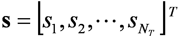
송신 신호를 살펴보면, N T 개의 송신 안테나가 있는 경우 전송 가능한 최대 정보는 N T 개이다. 전송 정보는 다음과 같이 표현될 수 있다.Looking at the transmission signal, when there are N T transmit antennas, the maximum information that can be transmitted is N T. The transmission information may be expressed as follows.
수학식 2
Figure PCTKR2012001891-appb-M000002
Equation 2
Figure PCTKR2012001891-appb-M000002
각각의 전송 정보
Figure PCTKR2012001891-appb-I000001
는 전송 전력이 다를 수 있다. 각각의 전송 전력을
Figure PCTKR2012001891-appb-I000002
라고 하면, 전송 전력이 조정된 전송 정보는 다음과 같이 표현될 수 있다.
Each transmission information
Figure PCTKR2012001891-appb-I000001
The transmit power may be different. Each transmit power
Figure PCTKR2012001891-appb-I000002
In this case, the transmission information whose transmission power is adjusted may be expressed as follows.
수학식 3
Figure PCTKR2012001891-appb-M000003
Equation 3
Figure PCTKR2012001891-appb-M000003
또한,
Figure PCTKR2012001891-appb-I000003
는 전송 전력의 대각행렬
Figure PCTKR2012001891-appb-I000004
를 이용해 다음과 같이 표현될 수 있다.
Also,
Figure PCTKR2012001891-appb-I000003
Is the diagonal of the transmit power
Figure PCTKR2012001891-appb-I000004
Can be expressed as
수학식 4
Figure PCTKR2012001891-appb-M000004
Equation 4
Figure PCTKR2012001891-appb-M000004
전송전력이 조정된 정보 벡터
Figure PCTKR2012001891-appb-I000005
에 가중치 행렬
Figure PCTKR2012001891-appb-I000006
가 적용되어 실제 전송되는 N T 개의 송신신호
Figure PCTKR2012001891-appb-I000007
가 구성되는 경우를 고려해 보자. 가중치 행렬
Figure PCTKR2012001891-appb-I000008
는 전송 정보를 전송 채널 상황 등에 따라 각 안테나에 적절히 분배해 주는 역할을 한다.
Figure PCTKR2012001891-appb-I000009
는 벡터
Figure PCTKR2012001891-appb-I000010
를 이용하여 다음과 같이 표현될 수 있다.
Information vector with adjusted transmission power
Figure PCTKR2012001891-appb-I000005
Weighting matrix
Figure PCTKR2012001891-appb-I000006
N T transmitted signals actually applied by applying
Figure PCTKR2012001891-appb-I000007
Consider the case where is configured. Weighting matrix
Figure PCTKR2012001891-appb-I000008
Plays a role in properly distributing transmission information to each antenna according to a transmission channel situation.
Figure PCTKR2012001891-appb-I000009
Vector
Figure PCTKR2012001891-appb-I000010
It can be expressed as follows.
수학식 5
Figure PCTKR2012001891-appb-M000005
Equation 5
Figure PCTKR2012001891-appb-M000005
여기에서,
Figure PCTKR2012001891-appb-I000011
i번째 송신 안테나와 j번째 정보간의 가중치를 의미한다.
Figure PCTKR2012001891-appb-I000012
는 프리코딩 행렬이라고도 불린다.
From here,
Figure PCTKR2012001891-appb-I000011
Denotes a weight between the i th transmit antenna and the j th information.
Figure PCTKR2012001891-appb-I000012
Is also called a precoding matrix.
수신신호는 N R 개의 수신 안테나가 있는 경우 각 안테나의 수신신호
Figure PCTKR2012001891-appb-I000013
은 벡터로 다음과 같이 표현될 수 있다.
Received signal is received signal of each antenna when there are N R receiving antennas
Figure PCTKR2012001891-appb-I000013
Can be expressed as a vector as
수학식 6
Figure PCTKR2012001891-appb-M000006
Equation 6
Figure PCTKR2012001891-appb-M000006
다중안테나 무선 통신 시스템에서 채널을 모델링하는 경우, 채널은 송수신 안테나 인덱스에 따라 구분될 수 있다. 송신 안테나 j로부터 수신 안테나 i를 거치는 채널을
Figure PCTKR2012001891-appb-I000014
로 표시하기로 한다.
Figure PCTKR2012001891-appb-I000015
에서, 인덱스의 순서가 수신 안테나 인덱스가 먼저, 송신 안테나의 인덱스가 나중임에 유의한다.
In the case of modeling a channel in a multi-antenna wireless communication system, channels may be divided according to transmit / receive antenna indexes. From the transmit antenna j to the channel through the receive antenna i
Figure PCTKR2012001891-appb-I000014
It is indicated by.
Figure PCTKR2012001891-appb-I000015
Note that in the order of the index, the receiving antenna index is first, and the index of the transmitting antenna is later.
한편, 도 5(b)은 N T 개의 송신 안테나에서 수신 안테나 i로의 채널을 도시한 도면이다. 상기 채널을 묶어서 벡터 및 행렬 형태로 표시할 수 있다. 도 5(b)에서, 총 N T 개의 송신 안테나로부터 수신 안테나 i로 도착하는 채널은 다음과 같이 나타낼 수 있다.FIG. 5B is a diagram illustrating a channel from N T transmit antennas to receive antenna i . The channels may be bundled and displayed in vector and matrix form. In FIG. 5 (b), a channel arriving from the total N T transmit antennas to the receive antenna i may be represented as follows.
수학식 7
Figure PCTKR2012001891-appb-M000007
Equation 7
Figure PCTKR2012001891-appb-M000007
따라서, N T 개의 송신 안테나로부터 N R 개의 수신 안테나로 도착하는 모든 채널은 다음과 같이 표현될 수 있다.Accordingly, all channels arriving from the N T transmit antennas to the N R receive antennas may be expressed as follows.
수학식 8
Figure PCTKR2012001891-appb-M000008
Equation 8
Figure PCTKR2012001891-appb-M000008
실제 채널에는 채널 행렬
Figure PCTKR2012001891-appb-I000016
를 거친 후에 백색잡음(AWGN; Additive White Gaussian Noise)이 더해진다. N R 개의 수신 안테나 각각에 더해지는 백색잡음
Figure PCTKR2012001891-appb-I000017
은 다음과 같이 표현될 수 있다.
Channel matrix on the actual channels
Figure PCTKR2012001891-appb-I000016
After passing through, Additive White Gaussian Noise (AWGN) is added. White noise added to each of N R receive antennas
Figure PCTKR2012001891-appb-I000017
Can be expressed as
수학식 9
Figure PCTKR2012001891-appb-M000009
Equation 9
Figure PCTKR2012001891-appb-M000009
상술한 수식 모델링을 통해 수신신호는 다음과 같이 표현될 수 있다.The received signal may be expressed as follows through the above-described mathematical modeling.
수학식 10
Figure PCTKR2012001891-appb-M000010
Equation 10
Figure PCTKR2012001891-appb-M000010
한편, 채널 상태를 나타내는 채널 행렬
Figure PCTKR2012001891-appb-I000018
의 행과 열의 수는 송수신 안테나의 수에 의해 결정된다. 채널 행렬
Figure PCTKR2012001891-appb-I000019
에서 행의 수는 수신 안테나의 수 N R 과 같고, 열의 수는 송신 안테나의 수 N T 와 같다. 즉, 채널 행렬
Figure PCTKR2012001891-appb-I000020
는 행렬이 N R ×N T 된다.
On the other hand, the channel matrix indicating the channel state
Figure PCTKR2012001891-appb-I000018
The number of rows and columns of is determined by the number of transmit and receive antennas. Channel matrix
Figure PCTKR2012001891-appb-I000019
The number of rows is equal to the number of receive antennas N R , and the number of columns is equal to the number of transmit antennas N T. That is, the channel matrix
Figure PCTKR2012001891-appb-I000020
The matrix is N R × N T.
행렬의 랭크(rank)는 서로 독립인(independent) 행 또는 열의 개수 중에서 최소 개수로 정의된다. 따라서, 행렬의 랭크는 행 또는 열의 개수 보다 클 수 없다. 채널 행렬
Figure PCTKR2012001891-appb-I000021
의 랭크(
Figure PCTKR2012001891-appb-I000022
)는 다음과 같이 제한된다.
The rank of a matrix is defined as the minimum number of rows or columns that are independent of each other. Thus, the rank of the matrix cannot be greater than the number of rows or columns. Channel matrix
Figure PCTKR2012001891-appb-I000021
Rank of (
Figure PCTKR2012001891-appb-I000022
) Is limited to
수학식 11
Figure PCTKR2012001891-appb-M000011
Equation 11
Figure PCTKR2012001891-appb-M000011
랭크의 다른 정의는 행렬을 고유치 분해(Eigen value decomposition) 하였을 때, 0이 아닌 고유치들의 개수로 정의할 수 있다. 유사하게, 랭크의 또 다른 정의는 특이치 분해(singular value decomposition) 하였을 때, 0이 아닌 특이치들의 개수로 정의할 수 있다. 따라서, 채널 행렬에서 랭크. 의 물리적인 의미는 주어진 채널에서 서로 다른 정보를 보낼 수 있는 최대 수라고 할 수 있다.Another definition of rank may be defined as the number of nonzero eigenvalues when the matrix is eigenvalue decomposition. Similarly, another definition of rank may be defined as the number of nonzero singular values when singular value decomposition is performed. Thus, rank in the channel matrix. The physical meaning of is the maximum number of different information that can be sent on a given channel.
본 문서의 설명에 있어서, MIMO 전송에 대한 '랭크(Rank)' 는 특정 시점 및 특정 주파수 자원에서 독립적으로 신호를 전송할 수 있는 경로의 수를 나타내며, '레이어(layer)의 개수' 는 각 경로를 통해 전송되는 신호 스트림의 개수를 나타낸다. 일반적으로 송신단은 신호 전송에 이용되는 랭크 수에 대응하는 개수의 레이어를 전송하기 때문에 특별한 언급이 없는 한 랭크는 레이어 개수와 동일한 의미를 가진다. In the description of this document, 'rank' for MIMO transmission refers to the number of paths that can independently transmit signals at specific time points and specific frequency resources, and 'number of layers' denotes each path. It indicates the number of signal streams transmitted through the system. In general, since the transmitting end transmits the number of layers corresponding to the number of ranks used for signal transmission, unless otherwise specified, the rank has the same meaning as the number of layers.
협력 멀티 포인트(Coordinated Multi-Point: CoMP)Coordinated Multi-Point (CoMP)
3GPP LTE-A 시스템의 개선된 시스템 성능 요구조건에 따라서, CoMP 송수신 기술 (co-MIMO, 공동(collaborative) MIMO 또는 네트워크 MIMO 등으로 표현되기도 함)이 제안되고 있다. CoMP 기술은 셀-경계(cell-edge)에 위치한 단말의 성능을 증가시키고 평균 섹터 수율(throughput)을 증가시킬 수 있다. In accordance with the improved system performance requirements of the 3GPP LTE-A system, CoMP transmission and reception techniques (also referred to as co-MIMO, collaborative MIMO, network MIMO, etc.) have been proposed. CoMP technology can increase the performance of the terminal located in the cell-edge (cell-edge) and increase the average sector throughput (throughput).
일반적으로, 주파수 재사용 인자(frequency reuse factor)가 1 인 다중-셀 환경에서, 셀-간 간섭(Inter-Cell Interference; ICI)으로 인하여 셀-경계에 위치한 단말의 성능과 평균 섹터 수율이 감소될 수 있다. 이러한 ICI를 저감하기 위하여, 기존의 LTE 시스템에서는 단말 특정 전력 제어를 통한 부분 주파수 재사용(fractional frequency reuse; FFR)과 같은 단순한 수동적인 기법을 이용하여 간섭에 의해 제한을 받은 환경에서 셀-경계에 위치한 단말이 적절한 수율 성능을 가지도록 하는 방법이 적용되었다. 그러나, 셀 당 주파수 자원 사용을 낮추기보다는, ICI를 저감하거나 ICI를 단말이 원하는 신호로 재사용하는 것이 보다 바람직할 수 있다. 위와 같은 목적을 달성하기 위하여, CoMP 전송 기법이 적용될 수 있다.In general, in a multi-cell environment having a frequency reuse factor of 1, inter-cell interference (ICI) may reduce performance and average sector yield of a terminal located in a cell boundary. have. In order to reduce such ICI, existing LTE system is located in a cell-boundary in an environment that is limited by interference by using a simple passive technique such as fractional frequency reuse (FFR) through UE-specific power control. The method for the terminal to have a proper yield performance has been applied. However, rather than reducing the use of frequency resources per cell, it may be more desirable to reduce the ICI or reuse the ICI as a signal desired by the terminal. In order to achieve the above object, CoMP transmission scheme may be applied.
하향링크의 경우에 적용될 수 있는 CoMP 기법은 크게 조인트-프로세싱(joint processing; JP) 기법 및 조정 스케줄링/빔포밍 (coordinated scheduling/beamforming; CS/CB) 기법으로 분류할 수 있다.CoMP schemes applicable to downlink can be classified into joint processing (JP) techniques and coordinated scheduling / beamforming (CS / CB) techniques.
JP 기법은 CoMP 협력 단위의 각각의 포인트(기지국)에서 데이터를 이용할 수 있다. CoMP 협력 단위는 협력 전송 기법에 이용되는 기지국들의 집합을 의미한다. JP 기법은 조인트 전송(Joint Transmission) 기법과 동적 셀 선택(Dynamic cell selection) 기법으로 분류할 수 있다.The JP technique may use data at each point (base station) of the CoMP cooperative unit. CoMP cooperative unit means a set of base stations used in a cooperative transmission scheme. The JP technique can be classified into a joint transmission technique and a dynamic cell selection technique.
조인트 전송 기법은, PDSCH 가 한번에 복수개의 포인트(CoMP 협력 단위의 일부 또는 전부)로부터 전송되는 기법을 말한다. 즉, 단일 단말로 전송되는 데이터는 복수개의 전송 포인트로부터 동시에 전송될 수 있다. 조인트 전송 기법에 의하면, 코히어런트하게(coherently) 또는 넌-코히어런트하게 (non-coherently) 수신 신호의 품질이 향상될 수 있고, 또한, 다른 단말에 대한 간섭을 능동적으로 소거할 수도 있다. The joint transmission technique refers to a technique in which a PDSCH is transmitted from a plurality of points (part or all of CoMP cooperative units) at a time. That is, data transmitted to a single terminal may be simultaneously transmitted from a plurality of transmission points. According to the joint transmission technique, the quality of a received signal may be improved coherently or non-coherently, and may also actively cancel interference with other terminals.
동적 셀 선택 기법은, PDSCH가 한번에 (CoMP 협력 단위의) 하나의 포인트로부터 전송되는 기법을 말한다. 즉, 특정 시점에서 단일 단말로 전송되는 데이터는 하나의 포인트로부터 전송되고, 그 시점에 협력 단위 내의 다른 포인트는 해당 단말에 대하여 데이터 전송을 하지 않으며, 해당 단말로 데이터를 전송하는 포인트는 동적으로 선택될 수 있다.Dynamic cell selection scheme refers to a scheme in which PDSCH is transmitted from one point (of CoMP cooperative units) at a time. That is, data transmitted to a single terminal at a specific time point is transmitted from one point, and other points in the cooperative unit do not transmit data to the corresponding terminal at that time point, and a point for transmitting data to the corresponding terminal is dynamically selected. Can be.
한편, CS/CB 기법에 의하면 CoMP 협력 단위들이 단일 단말에 대한 데이터 전송의 빔포밍을 협력적으로 수행할 수 있다. 여기서, 데이터는 서빙 셀에서만 전송되지만, 사용자 스케줄링/빔포밍은 해당 CoMP 협력 단위의 셀들의 조정에 의하여 결정될 수 있다.Meanwhile, according to the CS / CB scheme, CoMP cooperative units may cooperatively perform beamforming of data transmission for a single terminal. Here, data is transmitted only in the serving cell, but user scheduling / beamforming may be determined by coordination of cells of a corresponding CoMP cooperative unit.
한편, 상향링크의 경우에, 조정(coordinated) 다중-포인트 수신은 지리적으로 떨어진 복수개의 포인트들의 조정에 의해서 전송된 신호를 수신하는 것을 의미한다. 상향링크의 경우에 적용될 수 있는 CoMP 기법은 조인트 수신(Joint Reception; JR) 및 조정 스케줄링/빔포밍(coordinated scheduling/beamforming; CS/CB)으로 분류할 수 있다. On the other hand, in the case of uplink, coordinated multi-point reception means receiving a signal transmitted by coordination of a plurality of geographically separated points. CoMP schemes applicable to uplink may be classified into joint reception (JR) and coordinated scheduling / beamforming (CS / CB).
JR 기법은 PUSCH 를 통해 전송된 신호가 복수개의 수신 포인트에서 수신되는 것을 의미하고, CS/CB 기법은 PUSCH 가 하나의 포인트에서만 수신되지만 사용자 스케줄링/빔포밍은 CoMP 협력 단위의 셀들의 조정에 의해 결정되는 것을 의미한다. The JR scheme means that a signal transmitted through a PUSCH is received at a plurality of reception points. In the CS / CB scheme, a PUSCH is received only at one point, but user scheduling / beamforming is determined by coordination of cells of a CoMP cooperative unit. It means to be.
이러한 CoMP 시스템을 이용하면, 단말은 다중-셀 기지국(Multi-cell base station)으로부터 공동으로 데이터를 지원받을 수 있다. 또한, 각 기지국은 동일한 무선 주파수 자원(Same Radio Frequency Resource)을 이용하여 하나 이상의 단말에 동시에 지원함으로써 시스템의 성능을 향상시킬 수 있다. 또한, 기지국은 기지국과 단말 간의 채널상태정보에 기초하여 공간 분할 다중접속(Space Division Multiple Access: SDMA) 방법을 수행할 수도 있다. Using this CoMP system, the terminal can be jointly supported data from a multi-cell base station. In addition, each base station can improve the performance of the system by simultaneously supporting one or more terminals using the same radio frequency resource (Same Radio Frequency Resource). In addition, the base station may perform a space division multiple access (SDMA) method based on channel state information between the base station and the terminal.
CoMP 시스템에서 서빙 기지국 및 하나 이상의 협력 기지국들은 백본망(Backbone Network)을 통해 스케줄러(scheduler)에 연결된다. 스케줄러는 백본망을 통하여 각 기지국이 측정한 각 단말 및 협력 기지국 간의 채널 상태에 관한 채널 정보를 피드백 받아 동작할 수 있다. 예를 들어, 스케줄러는 서빙 기지국 및 하나 이상의 협력 기지국에 대하여 협력적 MIMO 동작을 위한 정보를 스케줄링할 수 있다. 즉, 스케줄러에서 각 기지국으로 협력적 MIMO 동작에 대한 지시를 직접 내릴 수 있다.In a CoMP system, a serving base station and one or more cooperating base stations are connected to a scheduler through a backbone network. The scheduler may operate by receiving feedback of channel information about channel states between respective terminals and the cooperative base stations measured by each base station through the backbone network. For example, the scheduler may schedule information for collaborative MIMO operation for the serving base station and one or more cooperating base stations. That is, the scheduler may directly give an indication of the cooperative MIMO operation to each base station.
상술한 바와 같이 CoMP 시스템은 복수개의 셀들을 하나의 그룹으로 묶어 가상 MIMO 시스템으로 동작하는 것이라 할 수 있으며, 기본적으로는 다중 안테나를 사용하는 MIMO 시스템의 통신 기법이 적용될 수 있다.As described above, the CoMP system may be referred to as operating as a virtual MIMO system by combining a plurality of cells into one group, and basically, a communication technique of a MIMO system using multiple antennas may be applied.
하향링크 채널상태정보(CSI) 피드백Downlink Channel Status Information (CSI) Feedback
MIMO 방식은 개-루프(open-loop) 방식과 폐-루프(closed-loop) 방식으로 구분될 수 있다. 개-루프 MIMO 방식은 MIMO 수신단으로부터의 채널상태정보의 피드백이 없이 송신단에서 MIMO 전송을 수행하는 것을 의미한다. 폐-루프 MIMO 방식은 MIMO 수신단으로부터의 채널상태정보를 피드백 받아 송신단에서 MIMO 전송을 수행하는 것을 의미한다. 폐-루프 MIMO 방식에서는 MIMO 송신 안테나의 다중화 이득(multiplexing gain)을 얻기 위해서 송신단과 수신단의 각각이 채널 상태정보를 바탕으로 빔포밍을 수행할 수 있다. 수신단(예를 들어, 단말)이 채널상태정보를 피드백할 수 있도록 송신단(예를 들어, 기지국)은 수신단(예를 들어, 단말)에게 상향링크 제어 채널 또는 상향링크 공유 채널을 할당할 수 있다. The MIMO scheme may be divided into an open-loop scheme and a closed-loop scheme. The open-loop MIMO scheme means that the transmitter performs MIMO transmission without feedback of the channel state information from the MIMO receiver. The closed-loop MIMO scheme means that the transmitter performs MIMO transmission by receiving the channel state information from the MIMO receiver. In the closed-loop MIMO scheme, each of the transmitter and the receiver may perform beamforming based on channel state information in order to obtain a multiplexing gain of the MIMO transmit antenna. The transmitting end (eg, the base station) may allocate an uplink control channel or an uplink shared channel to the receiving end (eg, the terminal) so that the receiving end (eg, the terminal) feeds back channel state information.
피드백되는 채널상태정보(CSI)는 랭크 지시자(RI), 프리코딩 행렬 인덱스(PMI) 및 채널품질지시자(CQI)를 포함할 수 있다. The channel state information (CSI) fed back may include a rank indicator (RI), a precoding matrix index (PMI), and a channel quality indicator (CQI).
RI는 채널 랭크에 대한 정보이다. 채널의 랭크는 동일한 시간-주파수 자원을 통해서 서로 다른 정보를 보낼 수 있는 레이어(또는 스트림)의 최대 개수를 의미한다. 랭크 값은 채널의 장기간(long term) 페이딩에 의해서 주로 결정되므로, PMI 및 CQI 에 비하여 일반적으로 더 긴 주기에 따라(즉, 덜 빈번하게) 피드백될 수 있다. RI is information about channel rank. The rank of the channel means the maximum number of layers (or streams) that can transmit different information through the same time-frequency resource. Since the rank value is determined primarily by the long term fading of the channel, it can be fed back over a generally longer period (ie less frequently) compared to PMI and CQI.
PMI는 송신단으로부터의 전송에 이용되는 프리코딩 행렬에 대한 정보이며, 채널의 공간 특성을 반영하는 값이다. 프리코딩이란 전송 레이어를 송신 안테나에 매핑시키는 것을 의미하며, 프리코딩 행렬에 의해 레이어-안테나 매핑 관계가 결정될 수 있다. PMI 는 신호대잡음및간섭비(Signal-to-Interference plus Noise Ratio; SINR) 등의 측정값(metric)을 기준으로 단말이 선호하는(preferred) 기지국의 프리코딩 행렬 인덱스에 해당한다. 프리코딩 정보의 피드백 오버헤드를 줄이기 위해서, 송신단과 수신단이 여러 가지 프리코딩 행렬을 포함하는 코드북을 미리 공유하고 있고, 해당 코드북에서 특정 프리코딩 행렬을 지시하는 인덱스만을 피드백하는 방식이 사용될 수 있다. PMI is information about a precoding matrix used for transmission from a transmitter and is a value reflecting spatial characteristics of a channel. Precoding means mapping a transmission layer to a transmission antenna, and a layer-antenna mapping relationship may be determined by a precoding matrix. The PMI corresponds to a precoding matrix index of a base station preferred by the terminal based on a metric such as a signal-to-interference plus noise ratio (SINR). In order to reduce the feedback overhead of precoding information, a scheme in which a transmitter and a receiver share a codebook including various precoding matrices in advance, and a method of feeding back only an index indicating a specific precoding matrix in the corresponding codebook may be used.
CQI는 채널 품질 또는 채널 세기를 나타내는 정보이다. CQI는 미리 결정된 MCS 조합으로서 표현될 수 있다. 즉, 피드백되는 CQI 인덱스는 해당하는 변조기법(modulation scheme) 및 코드 레이트(code rate)를 나타낸다. 일반적으로, CQI 는 기지국이 PMI 를 이용하여 공간 채널을 구성하는 경우에 얻을 수 있는 수신 SINR 을 반영하는 값이 된다. CQI is information indicating channel quality or channel strength. CQI may be expressed as a predetermined MCS combination. That is, the fed back CQI index indicates a corresponding modulation scheme and code rate. In general, the CQI is a value that reflects the received SINR that can be obtained when the base station configures the spatial channel using the PMI.
확장된 안테나 구성을 지원하는 시스템(예를 들어, LTE-A 시스템)에서는 다중사용자-MIMO (MU-MIMO) 방식을 이용하여 추가적인 다중사용자 다이버시티를 획득하는 것을 고려하고 있다. MU-MIMO 방식에서는 안테나 영역(domain)에서 다중화되는 단말들 간의 간섭 채널이 존재하므로, 다중사용자 중 하나의 단말이 피드백하는 채널상태정보를 기지국에서 이용하여 하향링크 전송을 수행하는 경우에 다른 단말에 대해서 간섭이 발생하지 않도록 하는 것이 필요하다. 따라서, MU-MIMO 동작이 올바르게 수행되기 위해서는 단일사용자-MIMO (SU-MIMO) 방식에 비하여 보다 높은 정확도의 채널상태정보가 피드백되어야 한다. Systems that support extended antenna configurations (eg, LTE-A systems) are considering acquiring additional multiuser diversity using a multiuser-MIMO (MU-MIMO) scheme. In the MU-MIMO scheme, since interference channels exist between terminals multiplexed in an antenna domain, when a base station performs downlink transmission using channel state information fed back by one terminal among multiple users, it is transmitted to another terminal. It is necessary to prevent interference from occurring. Accordingly, in order for the MU-MIMO operation to be performed correctly, the channel state information with higher accuracy than the single user-MIMO method must be fed back.
이와 같이 보다 정확한 채널상태정보를 측정 및 보고할 수 있도록, 기존의 RI, PMI 및 CQI 로 구성되는 CSI 를 개선한 새로운 CSI 피드백 방안이 적용될 수 있다. 예를 들어, 수신단이 피드백하는 프리코딩 정보가 2 개의 PMI 의 조합에 의해서 지시될 수 있다. 2 개의 PMI 중 하나(제 1 PMI)는, 장기간 및/또는 광대역(long term and/or wideband)의 속성을 가지고, W1으로 지칭될 수 있다. 2 개의 PMI 중 다른 하나(제 2 PMI)는, 단기간 및/또는 서브대역(short term and/or subband)의 속성을 가지고, W2으로 지칭될 수 있다. W1 및 W2의 조합(또는 함수)에 의해서 최종적인 PMI가 결정될 수 있다. 예를 들어, 최종 PMI 를 W 라 하면, W=W1*W2 또는 W=W2*W1 과 같이 정의될 수 있다. In order to measure and report more accurate channel state information as described above, a new CSI feedback scheme that improves the CSI composed of the existing RI, PMI, and CQI may be applied. For example, the precoding information fed back by the receiver may be indicated by a combination of two PMIs. One of the two PMIs (first PMI) has the property of long term and / or wideband and may be referred to as W1. The other one of the two PMIs (second PMI) has a short term and / or subband attribute and may be referred to as W2. The final PMI can be determined by the combination (or function) of W1 and W2. For example, if the final PMI is W, it may be defined as W = W1 * W2 or W = W2 * W1.
여기서, W1 은 채널의 주파수 및/또는 시간상 평균적인 특성을 반영한다. 다시 말하자면, W1 은 시간 상에서 장기간(long term) 채널의 특성을 반영하거나, 주파수 상에서 광대역(wideband) 채널의 특성을 반영하거나, 또는 시간상에서 장기간인 동시에 주파수 상에서 광대역 채널의 특성을 반영하는 채널 상태 정보로서 정의될 수 있다. W1 의 이러한 특성을 간략하게 표현하기 위해서, 본 문서에서는 W1 를 장기간-광대역 속성의 채널 상태 정보(또는, 장기간-광대역 PMI)라고 한다.Here, W1 reflects the frequency and / or time average characteristics of the channel. In other words, W1 reflects the characteristics of a long term channel in time, reflects the characteristics of a wideband channel in frequency, or reflects the characteristics of a wideband channel in frequency while being long term in time. It can be defined as. In order to express briefly this characteristic of W1, in this document, W1 is referred to as channel state information (or long term-wideband PMI) of long term-wideband attribute.
한편, W2 는 W1 에 비하여 상대적으로 순간적인(instantaneous) 채널 특성을 반영한다. 다시 말하자면, W2 는 시간 상에서 단기간(short term) 채널의 특성을 반영하거나, 주파수 상에서 서브대역(subband) 채널의 특성을 반영하거나, 또는 시간상에서 단기간인 동시에 주파수 상에서 서브대역 채널의 특성을 반영하는 채널 상태 정보로서 정의될 수 있다. W2 의 이러한 특성을 간략하게 표현하기 위해서, 본 문서에서는 W1 를 단기간-서브대역 속성의 채널 상태 정보(또는, 단기간-서브대역 PMI)라고 한다.On the other hand, W2 reflects a relatively instantaneous channel characteristic compared to W1. In other words, W2 is a channel that reflects the characteristics of a short term channel in time, reflects the characteristics of a subband channel in frequency, or reflects the characteristics of a subband channel in frequency while being short term in time. It can be defined as status information. To briefly express this characteristic of W2, in this document, W1 is referred to as channel state information (or short-term subband PMI) of short-term-subband attribute.
채널 상태를 나타내는 2 개의 서로 다른 속성의 정보(예를 들어, W1 및 W2)로부터 하나의 최종 프리코딩 행렬(W)을 결정할 수 있도록 하기 위해서, 각각의 속성의 채널 정보를 나타내는 프리코딩 행렬들로 구성되는 별도의 코드북 (즉, W1 에 대한 제 1 코드북 및 W2 에 대한 제 2 코드북)을 구성할 필요가 있다. 이와 같이 구성되는 코드북의 형태를 계층적 코드북(hierarchical codebook)이라 할 수 있다. 또한, 계층적 코드북을 이용하여 최종 사용될 코드북을 결정하는 것을, 계층적 코드북 변환(hierarchical codebook transformation)이라 할 수 있다. In order to be able to determine one final precoding matrix W from two different attribute information (e.g., W1 and W2) representing the channel state, the precoding matrices representing the channel information of each attribute are There is a need to construct separate codebooks that are constructed (ie, the first codebook for W1 and the second codebook for W2). The form of the codebook configured as described above may be referred to as a hierarchical codebook. In addition, determining a codebook to be finally used using the hierarchical codebook may be referred to as hierarchical codebook transformation.
계층적 코드북 변환 방식의 일례로서, 다음 수학식 12 와 같이 채널의 장기간 공분산 행렬(long term covariance matrix)을 이용하여 코드북을 변환할 수 있다. As an example of a hierarchical codebook conversion scheme, a codebook may be converted using a long term covariance matrix of a channel as shown in Equation 12 below.
수학식 12
Figure PCTKR2012001891-appb-M000012
Equation 12
Figure PCTKR2012001891-appb-M000012
상기 수학식 12 에서 W1(장기간-광대역 PMI)은 장기간-광대역 속성의 채널 정보를 반영하기 위해 만들어진 코드북(예를 들어, 제 1 코드북)을 구성하는 요소(즉, 코드워드(codeword))를 나타낸다. 즉, W1은 장기간-광대역 속성의 채널 정보를 반영하는 제 1 코드북에 포함되는 프리코딩 행렬에 해당한다. 한편, W2(단기간-서브대역 PMI)는 단기간-서브대역 속성의 채널 정보를 반영하기 위해서 만들어진 코드북(예를 들어, 제 2 코드북)을 구성하는 코드워드를 나타낸다. 즉, W2는 단기간-서브대역 속성의 채널 정보를 반영하는 제 2 코드북에 포함되는 프리코딩 행렬에 해당한다. W는 변환된 최종 코드북의 코드워드를 나타낸다. norm(A)는 행렬 A의 각각의 열(column)별 norm이 1로 정규화(normalization)된 행렬을 의미한다. In Equation 12, W1 (long-term wide-band PMI) represents an element (that is, a codeword) constituting a codebook (eg, a first codebook) made to reflect channel information of a long-term-wideband attribute. . That is, W1 corresponds to a precoding matrix included in the first codebook that reflects channel information of the long-term-band attribute. On the other hand, W2 (short-term subband PMI) represents a codeword constituting a codebook (for example, a second codebook) made to reflect channel information of short-term-subband attributes. That is, W2 corresponds to a precoding matrix included in the second codebook reflecting channel information of short-term subband attributes. W represents the codeword of the converted final codebook. norm (A) means a matrix in which norm is normalized to 1 for each column of the matrix A. FIG.
W1과 W2는 예시적으로 다음의 수학식 13과 같은 구조를 가질 수 있다.For example, W1 and W2 may have a structure as shown in Equation 13 below.
수학식 13
Figure PCTKR2012001891-appb-M000013
Equation 13
Figure PCTKR2012001891-appb-M000013
상기 수학식 13 에서 W1는 블록대각행렬(block diagonal matrix) 형태로서 정의될 수 있고, 각각의 블록은 동일한 행렬(X i )이다. 하나의 블록(X i )은 (Nt/2)×M 크기의 행렬로서 정의될 수 있다. 여기서, Nt 는 전송 안테나의 개수이다. 상기 수학식 13 에서 W2의
Figure PCTKR2012001891-appb-I000023
(p=k, l, ..., m)는 M×1 크기의 벡터이며, M 개의 벡터 성분 중에서 p 번째 성분은 1 이고, 나머지 성분들은 0 인 벡터를 나타낸다.
Figure PCTKR2012001891-appb-I000024
가 W1과 곱해지는 경우에 W1의 열들(columns) 중에서 p 번째 열이 선택되므로, 이러한 벡터를 선택 벡터(selection vector)라고 할 수 있다. 여기서, M 값이 커질수록 장기간-광대역(long term/wideband) 채널을 표현하기 위해 한번에 피드백 되는 벡터의 수가 많아지게 되며, 이에 따라 피드백 정확도가 높아지게 된다. 하지만 M 값이 커질 수록, 낮은 빈도로 피드백되는 W1의 코드북 크기(codebook size)는 줄어들고, 높은 빈도로 피드백되는 W2의 코드북 크기가 늘어남에 따라 결과적으로 피드백 오버헤드가 늘어나게 된다. 즉, 피드백 오버헤드와 피드백 정확도 간에 트레이드-오프(tradeoff)가 존재한다. 따라서, 적절한 피드백 정확도를 유지하면서도 피드백 오버헤드가 너무 크게 증가하지 않도록 M 값을 결정할 수 있다. 한편, W2 에서
Figure PCTKR2012001891-appb-I000025
,
Figure PCTKR2012001891-appb-I000026
,
Figure PCTKR2012001891-appb-I000027
는 각각 소정의 위상값을 나타낸다. 상기 수학식 13 에서 1≤k,l,m≤M 이고, k, l, m 은 각각 정수(integer)이다.
In Equation 13, W1 may be defined as a block diagonal matrix, and each block is the same matrix X i . One block X i may be defined as a matrix of size (Nt / 2) × M. Where Nt is the number of transmit antennas. W2 in Equation 13
Figure PCTKR2012001891-appb-I000023
( p = k , l , ..., m ) is a vector of M × 1 size, and the p- th component of the M vector components is 1, and the remaining components represent 0 vectors.
Figure PCTKR2012001891-appb-I000024
Since the p th column is selected among the columns of W1 when is multiplied by W1, such a vector may be referred to as a selection vector. Here, as the value of M increases, the number of vectors fed back at one time to represent a long term / wideband channel increases, thereby increasing feedback accuracy. However, as the M value increases, the codebook size of W1 that is fed back at a lower frequency decreases and the feedback overhead increases as the codebook size of W2 that is fed back at a higher frequency increases. That is, there is a tradeoff between feedback overhead and feedback accuracy. Thus, the M value can be determined so that the feedback overhead does not increase too much while maintaining proper feedback accuracy. On the other hand, in W2
Figure PCTKR2012001891-appb-I000025
,
Figure PCTKR2012001891-appb-I000026
,
Figure PCTKR2012001891-appb-I000027
Represents a predetermined phase value, respectively. In Equation 13, 1 ≦ k, l, m ≦ M and k, l, m are integers, respectively.
상기 수학식 13 과 같은 코드북 구조는, 크로스-극성(cross polarized; X-pol) 안테나 구성(configuration)을 사용하면서 안테나 간 간격이 조밀한 경우(통상적으로, 인접 안테나 간 거리가 신호 파장의 반 이하인 경우)에 발생하는 채널의 상관(correlation) 특성을 잘 반영하도록 설계한 구조이다. 예를 들어, 크로스-극성 안테나 구성은 다음의 표 1과 같이 나타낼 수 있다. The codebook structure shown in Equation 13 above uses a cross-polarized (X-pol) antenna configuration, where the spacing between antennas is dense (typically, the distance between adjacent antennas is less than half the signal wavelength). It is a structure designed to reflect the correlation characteristics of the channel occurring in the case). For example, the cross-polar antenna configuration can be shown in Table 1 below.
표 1
Figure PCTKR2012001891-appb-T000001
Table 1
Figure PCTKR2012001891-appb-T000001
상기 표 1에서 8Tx 크로스-극성 안테나 구성은, 2 개의 서로 직교하는 극성을 가지는 안테나 그룹으로 구성된다고 표현할 수 있다. 안테나 그룹 1 (안테나 1, 2, 3, 4)의 안테나들은 동일한 극성(예를 들어 수직 극성(vertical polarization))을 가지고 안테나 그룹 2(안테나 5, 6, 7, 8)의 안테나들은 동일한 극성(예를 들어 수평 극성(horizontal polarization))을 가질 수 있다. 또한, 두 안테나 그룹은 동일한 위치에 위치한다(co-located). 예를 들어, 안테나 1 과 5 는 동일한 위치에 설치되고, 안테나 2 과 6 은 동일한 위치에 설치되고, 안테나 3 과 7 은 동일한 위치에 설치되고, 안테나 2 과 8 은 동일한 위치에 설치될 수 있다. 달리 표현하자면, 하나의 안테나 그룹 내의 안테나들은 ULA(Uniform Linear Array)와 같이 동일한 극성을 가지고, 하나의 안테나 그룹 내의 안테나 간의 상관(correlation)은 선형 위상 증가(linear phase increment) 특성을 가진다. 또한, 안테나 그룹 간의 상관은 위상 회전(phase rotation)된 특성을 갖는다.In Table 1, the 8Tx cross-polar antenna configuration may be expressed as being composed of two antenna groups having polarities perpendicular to each other. Antennas of antenna group 1 ( antennas 1, 2, 3, 4) have the same polarity (eg vertical polarization) and antennas of antenna group 2 ( antennas 5, 6, 7, 8) have the same polarity ( For example, it may have horizontal polarization. In addition, the two antenna groups are co-located. For example, antennas 1 and 5 may be installed at the same position, antennas 2 and 6 may be installed at the same position, antennas 3 and 7 may be installed at the same position, and antennas 2 and 8 may be installed at the same position. In other words, the antennas in one antenna group have the same polarity as a uniform linear array (ULA), and the correlation between antennas in one antenna group has a linear phase increment characteristic. In addition, the correlation between antenna groups has a phase rotated characteristic.
코드북은 채널을 양자화(quantization)한 값이기 때문에, 실제 채널의 특성을 그대로 반영하여 코드북을 설계하는 것이 필요하다. 이와 같이 실제 채널 특성이 상기 수학식 13 과 같이 설계된 코드북의 코드워드에 반영되었음을 설명하기 위해서, 랭크 1 코드북을 예시적으로 설명한다. 아래의 수학식 14 는 랭크 1 인 경우의 W1 코드워드와 W2 코드워드의 곱으로 최종 코드워드(W)가 결정되는 예시를 나타낸 것이다.Since the codebook is a quantized value of the channel, it is necessary to design the codebook to reflect the characteristics of the actual channel. In order to explain that the actual channel characteristics are reflected in the codeword of the codebook designed as in Equation 13, the rank 1 codebook will be described as an example. Equation 14 below shows an example in which the final codeword W is determined by multiplying the W1 codeword by the rank 1 and the W2 codeword.
수학식 14
Figure PCTKR2012001891-appb-M000014
Equation 14
Figure PCTKR2012001891-appb-M000014
상기 수학식 14 에서 최종 코드워드는 Nt×1 의 벡터로 표현되며, 상위 벡터(
Figure PCTKR2012001891-appb-I000028
)와 하위 벡터(
Figure PCTKR2012001891-appb-I000029
)의 두 개의 벡터로 구조화되어 있다. 상위 벡터(
Figure PCTKR2012001891-appb-I000030
)는 크로스 극성 안테나의 수평 극성 안테나 그룹의 상관 특성을 나타내고, 하위 벡터 (
Figure PCTKR2012001891-appb-I000031
)는 수직 극성 안테나 그룹의 상관 특성을 나타낸다. 또한,
Figure PCTKR2012001891-appb-I000032
는 각각의 안테나 그룹 내의 안테나 간 상관 특성을 반영하여 선형 위상 증가를 갖는 벡터(예를 들어, DFT 행렬)로 표현할 수 있다.
In Equation 14, the final codeword is represented by a vector of Nt × 1, and a higher vector (
Figure PCTKR2012001891-appb-I000028
) And subvector (
Figure PCTKR2012001891-appb-I000029
Structured as two vectors of). Parent vector
Figure PCTKR2012001891-appb-I000030
) Represents the correlation characteristics of the horizontal polarity antenna group of the cross polarity antenna, and the lower vector (
Figure PCTKR2012001891-appb-I000031
) Represents the correlation characteristics of the vertical polar antenna group. Also,
Figure PCTKR2012001891-appb-I000032
May be expressed as a vector having a linear phase increase (eg, a DFT matrix) by reflecting correlation characteristics between antennas in each antenna group.
전술한 바와 같은 코드북을 이용하는 경우에 단일 코드북을 이용하는 경우에 비하여 높은 정확도의 채널 피드백이 가능해진다. 이와 같이 높은 정확도의 채널 피드백을 이용하여 단일-셀 MU-MIMO가 가능해질 수 있고, 이와 유사한 이유로 CoMP 동작에서도 높은 정확도의 채널 피드백이 요구된다. 예를 들어, CoMP JT 동작의 경우 여러 기지국이 특정 UE에게 동일한 데이터를 협력 전송하므로 이론적으로 복수개의 안테나가 지리적으로 분산되어 있는 MIMO 시스템으로 간주할 수 있다. 즉, CoMP JT에서 MU-MIMO 동작을 하는 경우에서도, 단일-셀 MU-MIMO와 마찬가지로, 공동-스케줄링(co-scheduling)되는 UE간 간섭을 피하기 위해 높은 수준의 채널 정보의 정확도가 요구된다. 또한, CoMP CB 동작의 경우 역시 인접 셀이 서빙 셀에게 주는 간섭을 회피하기 위해서 정교한 채널 정보가 요구된다.In the case of using the codebook as described above, channel feedback with higher accuracy is possible than in the case of using a single codebook. As such, single-cell MU-MIMO can be enabled by using high accuracy channel feedback, and similarly, high accuracy channel feedback is required in CoMP operation. For example, in the case of CoMP JT operation, since several base stations cooperatively transmit the same data to a specific UE, it may theoretically be regarded as a MIMO system in which a plurality of antennas are geographically dispersed. That is, even in the case of MU-MIMO operation in CoMP JT, as in single-cell MU-MIMO, high level of channel information accuracy is required to avoid co-scheduling between UEs. In addition, in the case of CoMP CB operation, sophisticated channel information is required to avoid interference caused by the neighboring cell to the serving cell.
참조 신호 (Reference Signal; RS) Reference Signal (RS)
무선 통신 시스템에서 패킷을 전송할 때, 전송되는 패킷은 무선 채널을 통해서 전송되기 때문에 전송과정에서 신호의 왜곡이 발생할 수 있다. 왜곡된 신호를 수신측에서 올바로 수신하기 위해서는 채널 정보를 이용하여 수신 신호에서 왜곡을 보정하여야 한다. 채널 정보를 알아내기 위해서, 송신측과 수신측에서 모두 알고 있는 신호를 전송하여, 상기 신호가 채널을 통해 수신될 때의 왜곡 정도를 가지고 채널 정보를 알아내는 방법을 주로 사용한다. 상기 신호를 파일럿 신호 (Pilot Signal) 또는 참조 신호 (Reference Signal)라고 한다. 다중안테나를 사용하여 데이터를 송수신하는 경우에는 각 송신 안테나와 수신 안테나 사이의 채널 상황을 알아야 올바른 신호를 수신할 수 있다. 따라서, 각 송신 안테나 별로 별도의 참조 신호가 존재하여야 한다.When transmitting a packet in a wireless communication system, since the transmitted packet is transmitted through a wireless channel, signal distortion may occur during the transmission process. In order to correctly receive the distorted signal at the receiving end, the distortion must be corrected in the received signal using the channel information. In order to find out the channel information, a method of transmitting the signal known to both the transmitting side and the receiving side and finding the channel information with the distortion degree when the signal is received through the channel is mainly used. The signal is called a pilot signal or a reference signal. When transmitting and receiving data using multiple antennas, it is necessary to know the channel condition between each transmitting antenna and the receiving antenna to receive the correct signal. Therefore, a separate reference signal must exist for each transmit antenna.
기존의 무선 통신 시스템(예를 들어, 3GPP LTE 릴리즈-8 또는 릴리즈-9 시스템)에서는, 하향링크 참조신호는 셀 내의 모든 단말이 공유하는 공용 참조신호(Common Reference Signal; CRS)와 특정 단말만을 위한 전용 참조신호(Dedicated Reference Signal; DRS)를 정의한다. 이러한 참조신호들에 의해 채널 추정 및 복조를 위한 정보가 제공될 수 있다. In an existing wireless communication system (eg, 3GPP LTE Release-8 or Release-9 system), a downlink reference signal is a common reference signal (CRS) shared by all terminals in a cell and only for a specific terminal. Dedicated Reference Signal (DRS) is defined. Such reference signals may provide information for channel estimation and demodulation.
수신측(단말)은 CRS로부터 채널의 상태를 추정하여 CQI(Channel Quality Indicator), PMI(Precoding Matrix Index) 및/또는 RI(Rank Indicator)와 같은 채널 품질과 관련된 지시자를 송신측(기지국)으로 피드백할 수 있다. CRS는 셀-특정(cell-specific) 참조신호라 불릴 수도 있다. The receiver (terminal) estimates the state of the channel from the CRS and feeds back indicators related to channel quality such as channel quality indicator (CQI), precoding matrix index (PMI), and / or rank indicator (RI) to the transmitter (base station). can do. The CRS may be called a cell-specific reference signal.
DRS는 PDSCH 상의 데이터의 복조가 필요한 경우에 해당 RE를 통하여 전송될 수 있다. 단말은 상위계층으로부터 DRS의 존재 여부에 대하여 지시받을 수 있고, 해당 PDSCH가 매핑된 경우에만 DRS가 유효하다는 것에 대하여 지시받을 수 있다. DRS는 단말-특정(UE-specific) 참조신호 또는 복조용 참조신호(Demodulation Reference Signal; DMRS)라 불릴 수도 있다. The DRS may be transmitted through the corresponding RE when demodulation of data on the PDSCH is required. The UE may be instructed as to whether DRS is present from a higher layer and may be instructed that the DRS is valid only when the corresponding PDSCH is mapped. The DRS may also be called a UE-specific reference signal or a demodulation reference signal (DMRS).
기존의 3GPP LTE (예를 들어, LTE 릴리즈-8 또는 릴리즈-9) 시스템보다 높은 스펙트럼 효율성(Spectral Efficiency)를 지원하기 위하여, 확장된 안테나 구성을 갖는 시스템(예를 들어, LTE-A(Advanced) 시스템)을 설계할 수 있다. 확장된 안테나 구성은, 예를 들어, 8개의 전송 안테나 구성일 수 있다. 이러한 확장된 안테나 구성을 갖는 시스템에서 기존의 안테나 구성에서 동작하는 단말들을 지원, 즉, 역방향 호환성(backward compatibility)을 지원할 필요가 있다. 따라서, 기존의 안테나 구성에 따른 참조신호 패턴을 지원하고, 추가적인 안테나 구성에 대한 새로운 참조신호 패턴을 설계할 필요가 있다. In order to support higher spectral efficiency than existing 3GPP LTE (eg, LTE Release-8 or Release-9) systems, systems with extended antenna configurations (eg, LTE-A (Advanced) System). The extended antenna configuration can be, for example, eight transmit antenna configurations. In a system having such an extended antenna configuration, it is necessary to support terminals operating in the existing antenna configuration, that is, backward compatibility. Accordingly, there is a need to support a reference signal pattern according to an existing antenna configuration and to design a new reference signal pattern for an additional antenna configuration.
LTE 시스템에서의 하향링크 RS는 최대 4개의 안테나 포트에 대해서만 정의되어 있으므로, LTE-A 시스템에서 기지국이 4개 이상 최대 8개의 하향 링크 송신 안테나를 가질 경우 이들 안테나 포트들에 대한 RS가 추가적으로 정의되어야 한다. 최대 8개의 송신 안테나 포트에 대한 RS로서, 채널 측정을 위한 RS와 데이터 복조를 위한 RS 두 가지가 모두 고려되어야 한다. Since the downlink RS in the LTE system is defined for up to four antenna ports only, if the base station has four or more up to eight downlink transmission antennas in the LTE-A system, RSs for these antenna ports must be additionally defined. do. As RS for up to eight transmit antenna ports, both RS for channel measurement and RS for data demodulation should be considered.
RS 전송 관점에서 보았을 때, LTE 표준에서 정의되어 있는 CRS가 전 대역으로 매 서브프레임마다 전송되는 시간-주파수 영역에 최대 8개의 송신 안테나 포트에 대한 RS를 추가하는 경우, RS 오버헤드가 지나치게 커지게 된다. 따라서, 최대 8 안테나 포트에 대한 RS를 새롭게 설계함에 있어서 RS 오버헤드를 줄이는 것이 고려되어야 한다.From the point of view of RS transmission, if RS is added for up to eight transmit antenna ports in the time-frequency domain where CRS defined in the LTE standard is transmitted every subframe over the entire band, the RS overhead becomes excessively large. do. Therefore, in designing RS for up to 8 antenna ports, consideration should be given to reducing RS overhead.
LTE-A 시스템에서 새롭게 도입되는 RS는 크게 2 가지로 분류할 수 있다. 그 중 하나는 RI, PMI, CQI 등의 계산/선택을 위한 채널 측정 목적의 RS인 채널상태정보-참조신호(Channel State Information RS; CSI-RS)이고, 다른 하나는 최대 8 개의 전송 안테나를 통해 전송되는 데이터를 복조하기 위한 목적의 RS 인 복조-참조신호(DeModulation RS; DM RS)이다. RS newly introduced in LTE-A system can be classified into two types. One of them is a Channel State Information RS (CSI-RS), which is an RS for channel measurement purposes for calculation / selection of RI, PMI, CQI, etc., and the other is through up to eight transmit antennas. A demodulation-reference signal (DM RS), which is an RS for demodulating transmitted data.
채널 측정 목적의 CSI-RS는, 기존의 LTE 시스템에서의 CRS가 채널 측정, 핸드오버 등의 측정 등의 목적과 동시에 데이터 복조를 위해 사용되는 것과 달리, 채널 측정 위주의 목적을 위해서 설계되는 특징이 있다. 물론 CSI-RS 역시 핸드오버 등의 측정 등의 목적으로도 사용될 수도 있다. CSI-RS가 채널 상태에 대한 정보를 얻는 목적으로만 전송되므로, 기존의 LTE 시스템에서의 CRS와 달리, 매 서브프레임마다 전송되지 않아도 된다. 따라서, CSI-RS의 오버헤드를 줄이기 위하여 CSI-RS는 시간 축 상에서 간헐적으로(예를 들어, 주기적으로) 전송되도록 설계될 수 있다.CSI-RS for channel measurement purposes is characterized in that the CRS in the existing LTE system is designed for channel measurement-oriented purposes, unlike the CRS used for data demodulation at the same time as the channel measurement, handover, etc. have. Of course, the CSI-RS may also be used for the purpose of measuring handover. Since the CSI-RS is transmitted only for the purpose of obtaining channel state information, unlike the CRS in the existing LTE system, the CSI-RS does not need to be transmitted every subframe. Thus, to reduce the overhead of the CSI-RS, the CSI-RS may be designed to be transmitted intermittently (eg, periodically) on the time axis.
한편, 어떤 하향링크 서브프레임 상에서 데이터가 전송되는 경우에는, 데이터 전송이 스케줄링된 단말에게 전용으로(dedicated) DM RS가 전송된다. 특정 단말 전용의 DM RS는, 해당 단말이 스케줄링된 자원영역, 즉 해당 단말에 대한 데이터가 전송되는 시간-주파수 영역에서만 전송되도록 설계될 수 있다.On the other hand, when data is transmitted on a downlink subframe, a dedicated DM RS is transmitted to a terminal scheduled for data transmission. The DM RS dedicated to a specific terminal may be designed to be transmitted only in a resource region in which the terminal is scheduled, that is, in a time-frequency region in which data for the terminal is transmitted.
한편, 상향링크 상에서 전송되는 참조신호에는 UL DMRS 및 SRS(Sounding Reference Signal)가 존재한다. UL DMRS는 PUSCH 복조를 위해서 전송되는 참조신호이며, 일반 CP의 경우에 각 슬롯의 7 개의 SC-FDMA 심볼 중에서 4 번째 SC-FDMA 심볼 상에서 전송될 수 있다. SRS에 대해서는 이하에서 자세하게 설명한다. Meanwhile, UL DMRS and SRS (Sounding Reference Signal) are present in the reference signal transmitted on the uplink. The UL DMRS is a reference signal transmitted for PUSCH demodulation and may be transmitted on a fourth SC-FDMA symbol among seven SC-FDMA symbols of each slot in the case of a normal CP. The SRS will be described in detail below.
사운딩 참조 신호(SRS)Sounding Reference Signal (SRS)
사운딩 참조 신호(Sounding Reference Signal; SRS)는 주로 기지국이 채널 품질 측정을 하여 상향링크 상에서 주파수-선택적(frequency-selective) 스케줄링을 위해 사용되며, 상향링크 데이터 및/또는 제어 정보 전송과 연관되지는 않는다. 그러나, 이에 제한되는 것은 아니고, SRS는 향상된 전력 제어의 목적 또는 최근에 스케줄링되지 않은 단말들의 다양한 시작 기능(start-up function)을 지원하는 목적으로 사용될 수도 있다. 시작 기능은, 예를 들어, 초기 변조및코딩 기법(Modulation and Coding Scheme; MCS), 데이터 전송을 위한 초기 전력 제어, 타이밍 정렬(timing advance) 및 주파수 반-선택적 스케줄링 (서브프레임의 첫 번째 슬롯에서는 주파수 자원이 선택적으로 할당되고 두 번째 슬롯에서는 다른 주파수로 유사-무작위(pseudo-random)적으로 호핑되는 스케줄링) 등을 포함할 수 있다.The sounding reference signal (SRS) is mainly used for frequency-selective scheduling on uplink by a base station measuring channel quality and is not associated with uplink data and / or control information transmission. Do not. However, the present invention is not limited thereto, and the SRS may be used for the purpose of improved power control or for supporting various start-up functions of terminals not recently scheduled. The start function is, for example, an initial modulation and coding scheme (MCS), initial power control for data transmission, timing advance and frequency anti-selective scheduling (in the first slot of the subframe). Frequency resources are selectively allocated and may include pseudo-random hopping to other frequencies in the second slot).
또한, SRS 는 무선 채널이 상향링크와 하향링크 간에 상호적인(reciprocal)이라는 가정하에 하향링크 채널 품질 측정을 위해 사용될 수도 있다. 이러한 가정은, 상향링크와 하향링크가 동일한 주파수 대역을 공유하고 시간 영역에서 구별되는 시분할듀플렉스(time division duplex; TDD) 시스템에서 특히 유효하다.In addition, the SRS may be used for downlink channel quality measurement under the assumption that the radio channel is reciprocal between uplink and downlink. This assumption is particularly valid in time division duplex (TDD) systems where uplink and downlink share the same frequency band and are distinguished in the time domain.
셀 내의 임의의 단말에 의하여 SRS가 전송되는 서브프레임은 셀-특정 브로드캐스트 시그널링에 의하여 지시된다. 4-비트의 셀-특정 'SrsSubframeConfiguration' 파라미터는 각각의 무선 프레임 내에서 SRS가 전송될 수 있는 서브프레임의 15 가지 가능한 구성들을 나타낸다. 이러한 구성에 의해 네트워크 배치 시나리오에 따라 SRS 오버헤드를 조정할 수 있는 유연성이 제공될 수 있다. 상기 파라미터의 나머지 하나(16 번째)의 구성은 셀 내의 SRS 전송을 완전히 끄는(switch-off) 것으로, 예를 들어, 주로 고속의 단말들을 서빙하는 셀에 적절할 수 있다.The subframe in which the SRS is transmitted by any terminal in the cell is indicated by cell-specific broadcast signaling. The 4-bit cell-specific 'SrsSubframeConfiguration' parameter represents fifteen possible configurations of subframes in which an SRS can be transmitted within each radio frame. This configuration can provide flexibility to adjust SRS overhead according to network deployment scenarios. The configuration of the other (16th) of the parameter is to switch off the SRS transmission in the cell completely, for example, may be suitable for a cell serving mainly high speed terminals.
SRS는 항상 구성된 서브프레임의 마지막 SC-FDMA 심볼 상에서 전송될 수 있다. 따라서, SRS와 UL DMRS는 상이한 SC-FDMA 심볼 상에 위치된다. PUSCH 데이터 전송은 SRS 전송을 위해 지정된 SC-FDMA 심볼 상에서 허용되지 않으며, 이에 따라 사운딩 오버헤드가 가장 높은 경우 (즉, 모든 서브프레임에서 SRS 전송 심볼이 존재하는 경우)에도 대략 7% 를 넘지 않는다.The SRS may always be transmitted on the last SC-FDMA symbol of the configured subframe. Thus, the SRS and UL DMRS are located on different SC-FDMA symbols. PUSCH data transmissions are not allowed on the SC-FDMA symbols designated for SRS transmissions, and therefore do not exceed approximately 7% even when the sounding overhead is highest (that is, when there is an SRS transmission symbol in every subframe). .
각각의 SRS 심볼은 주어진 시간 단위 및 주파수 대역에 대하여 기본 시퀀스(랜덤 시퀀스 또는 ZC(Zadoff-Chu)-기반 시퀀스 집합)에 의하여 생성되고, 셀 내의 모든 단말은 동일한 기본 시퀀스를 사용한다. 이때, 동일한 시간 단위 및 동일한 주파수 대역에서 셀 내의 복수개의 단말로부터의 SRS 전송은, 해당 복수개의 단말들에게 할당되는 기본 시퀀스의 상이한 순환 시프트(cyclic shifts)에 의하여 직교적으로(orthogonally) 구별된다. 상이한 셀의 SRS 시퀀스는 셀 마다 상이한 기본 시퀀스를 할당함으로써 구별될 수 있지만, 상이한 기본 시퀀스들 간에 직교성은 보장되지 않는다.Each SRS symbol is generated by a base sequence (random sequence or Zadoff-Chu-based sequence set) for a given time unit and frequency band, and all terminals in a cell use the same base sequence. In this case, SRS transmissions from a plurality of terminals in a cell in the same time unit and the same frequency band are orthogonally distinguished by different cyclic shifts of a basic sequence allocated to the plurality of terminals. SRS sequences of different cells can be distinguished by assigning different base sequences from cell to cell, but orthogonality between different base sequences is not guaranteed.
물리상향링크제어채널(PUCCH)Physical Uplink Control Channel (PUCCH)
PUCCH를 통하여 전송되는 상향링크 제어 정보(UCI)는, 스케줄링 요청(Scheduling Request; SR), HARQ ACK/NACK 정보, 및 하향링크 채널 측정 정보를 포함할 수 있다. The uplink control information (UCI) transmitted through the PUCCH may include a scheduling request (SR), HARQ ACK / NACK information, and downlink channel measurement information.
HARQ ACK/NACK 정보는 PDSCH 상의 하향링크 데이터 패킷의 디코딩 성공 여부에 따라 생성될 수 있다. 기존의 무선 통신 시스템에서, 하향링크 단일 코드워드(codeword) 전송에 대해서는 ACK/NACK 정보로서 1 비트가 전송되고, 하향링크 2 코드워드 전송에 대해서는 ACK/NACK 정보로서 2 비트가 전송된다. HARQ ACK / NACK information may be generated according to whether the decoding of the downlink data packet on the PDSCH is successful. In a conventional wireless communication system, one bit is transmitted as ACK / NACK information for downlink single codeword transmission, and two bits are transmitted as ACK / NACK information for downlink 2 codeword transmission.
채널 측정 정보는 다중입출력(Multiple Input Multiple Output; MIMO) 기법과 관련된 피드백 정보를 지칭하며, 채널품질지시자(Channel Quality Indicator; CQI), 프리코딩행렬인덱스(Precoding Matrix Index; PMI) 및 랭크지시자(Rank Indicator; RI)를 포함할 수 있다. 이들 채널 측정 정보를 통칭하여 CQI 라고 표현할 수도 있다. CQI 의 전송을 위하여 서브프레임 당 20 비트가 사용될 수 있다. The channel measurement information refers to feedback information related to a multiple input multiple output (MIMO) scheme, and includes channel quality indicator (CQI), precoding matrix index (PMI), and rank indicator (Rank). Indicator (RI). These channel measurement information may be collectively expressed as CQI. 20 bits per subframe may be used for transmission of the CQI.
PUCCH는 BPSK(Binary Phase Shift Keying)과 QPSK(Quadrature Phase Shift Keying) 기법을 사용하여 변조될 수 있다. PUCCH를 통하여 복수개의 단말의 제어 정보가 전송될 수 있고, 각 단말들의 신호를 구별하기 위하여 코드분할다중화(Code Division Multiplexing; CDM)을 수행하는 경우에 길이 12 의 CAZAC(Constant Amplitude Zero Autocorrelation) 시퀀스를 주로 사용한다. CAZAC 시퀀스는 시간 영역(time domain) 및 주파수 영역(frequency domain)에서 일정한 크기(amplitude)를 유지하는 특성을 가지므로 단말의 PAPR(Peak-to-Average Power Ratio) 또는 CM(Cubic Metric)을 낮추어 커버리지를 증가시키기에 적합한 성질을 가진다. 또한, PUCCH를 통해 전송되는 하향링크 데이터 전송에 대한 ACK/NACK 정보는 직교 시퀀스(orthgonal sequence) 또는 직교 커버(orthogonal cover; OC)를 이용하여 커버링된다.PUCCH may be modulated using Binary Phase Shift Keying (BPSK) and Quadrature Phase Shift Keying (QPSK). Control information of a plurality of terminals may be transmitted through the PUCCH, and a constant amplitude zero autocorrelation (CAZAC) sequence having a length of 12 when code division multiplexing (CDM) is performed to distinguish signals of the terminals Mainly used. Since the CAZAC sequence has a characteristic of maintaining a constant amplitude in the time domain and the frequency domain, the coverage is reduced by reducing the Peak-to-Average Power Ratio (PAPR) or the Cubic Metric (CM) of the UE. It has a suitable property to increase. In addition, ACK / NACK information for downlink data transmission transmitted through the PUCCH is covered using an orthogonal sequence or an orthogonal cover (OC).
또한, PUCCH 상으로 전송되는 제어정보는 서로 다른 순환 시프트(cyclic shift; CS) 값을 가지는 순환 시프트된 시퀀스(cyclically shifted sequence)를 이용하여 구별될 수 있다. 순환 시프트된 시퀀스는 기본 시퀀스(base sequence)를 특정 CS 양(cyclic shift amount) 만큼 순환 시프트시켜 생성할 수 있다. 특정 CS 양은 순환 시프트 인덱스(CS index)에 의해 지시된다. 채널의 지연 확산(delay spread)에 따라 사용가능한 순환 시프트의 수는 달라질 수 있다. 다양한 종류의 시퀀스가 기본 시퀀스로 사용될 수 있으며, 전술한 CAZAC 시퀀스는 그 일례이다. In addition, the control information transmitted on the PUCCH can be distinguished using a cyclically shifted sequence having different cyclic shift (CS) values. The cyclically shifted sequence may be generated by cyclically shifting a base sequence by a specific cyclic shift amount. The specific CS amount is indicated by the cyclic shift index (CS index). Depending on the delay spread of the channel, the number of available cyclic shifts may vary. Various kinds of sequences may be used as the base sequence, and the above-described CAZAC sequence is one example.
또한, 단말이 하나의 서브프레임에서 전송할 수 있는 제어 정보의 양은 제어 정보의 전송에 이용가능한 SC-FDMA 심볼의 개수(즉, PUCCH 의 코히어런트(coherent) 검출을 위한 참조신호(RS) 전송에 이용되는 SC-FDMA 심볼을 제외한 SC-FDMA 심볼들)에 따라 결정될 수 있다. In addition, the amount of control information that can be transmitted in one subframe by the UE depends on the number of SC-FDMA symbols available for transmission of the control information (that is, RS transmission for coherent detection of PUCCH). SC-FDMA symbols except for the SC-FDMA symbol used).
3GPP LTE 시스템에서 PUCCH 는, 전송되는 제어 정보, 변조 기법, 제어 정보의 양 등에 따라 총 7 가지 상이한 포맷으로 정의되며, 각각의 PUCCH 포맷에 따라서 전송되는 상향링크 제어 정보(uplink control information; UCI)의 속성은 다음의 표 2와 같이 요약할 수 있다. In the 3GPP LTE system, PUCCH is defined in seven different formats according to transmitted control information, modulation scheme, amount of control information, and the like. Uplink control information (UCI) The attributes can be summarized as shown in Table 2 below.
표 2
Figure PCTKR2012001891-appb-T000002
TABLE 2
Figure PCTKR2012001891-appb-T000002
PUCCH 포맷 1은 SR의 단독 전송에 사용된다. SR 단독 전송의 경우에는 변조되지 않은 파형이 적용되며, 이에 대해서는 후술하여 자세하게 설명한다. PUCCH format 1 is used for single transmission of SR. In the case of SR transmission alone, an unmodulated waveform is applied, which will be described later in detail.
PUCCH 포맷 1a 또는 1b는 HARQ ACK/NACK의 전송에 사용된다. 임의의 서브프레임에서 HARQ ACK/NACK이 단독으로 전송되는 경우에는 PUCCH 포맷 1a 또는 1b를 사용할 수 있다. 또는, PUCCH 포맷 1a 또는 1b를 사용하여 HARQ ACK/NACK 및 SR 이 동일 서브프레임에서 전송될 수도 있다. PUCCH format 1a or 1b is used for transmission of HARQ ACK / NACK. When HARQ ACK / NACK is transmitted alone in any subframe, PUCCH format 1a or 1b may be used. Alternatively, HARQ ACK / NACK and SR may be transmitted in the same subframe using PUCCH format 1a or 1b.
PUCCH 포맷 2는 CQI의 전송에 사용되고, PUCCH 포맷 2a 또는 2b는 CQI 및 HARQ ACK/NACK의 전송에 사용된다. 확장된 CP 의 경우에는 PUCCH 포맷 2가 CQI 및 HARQ ACK/NACK 의 전송에 사용될 수도 있다. PUCCH format 2 is used for transmission of CQI, and PUCCH format 2a or 2b is used for transmission of CQI and HARQ ACK / NACK. In the case of an extended CP, PUCCH format 2 may be used for transmission of CQI and HARQ ACK / NACK.
도 6은 상향링크 물리자원블록에서 PUCCH 포맷들이 PUCCH 영역들에 매핑되는 형태를 도시한다. 도 6에서
Figure PCTKR2012001891-appb-I000033
는 상향링크에서의 자원블록의 개수를 나타내고, 0, 1,...
Figure PCTKR2012001891-appb-I000034
는 물리자원블록의 번호를 의미한다. 기본적으로, PUCCH는 상향링크 주파수 블록의 양쪽 끝단(edge)에 매핑된다. 도 6에서 도시하는 바와 같이, m=0,1 로 표시되는 PUCCH 영역에 PUCCH 포맷 2/2a/2b 가 매핑되며, 이는 PUCCH 포맷 2/2a/2b 가 대역-끝단(band-edge)에 위치한 자원블록들에 매핑되는 것으로 표현할 수 있다. 또한, m=2 로 표시되는 PUCCH 영역에 PUCCH 포맷 2/2a/2b 및 PUCCH 포맷 1/1a/1b 가 함께(mixed) 매핑될 수 있다. 다음으로, m=3,4,5 로 표시되는 PUCCH 영역에 PUCCH 포맷 1/1a/1b 가 매핑될 수 있다. PUCCH 포맷 2/2a/2b 에 의해 사용가능한 PUCCH RB들의 개수(
Figure PCTKR2012001891-appb-I000035
)는 브로드캐스팅 시그널링에 의해서 셀 내의 단말들에게 지시될 수 있다.
FIG. 6 illustrates a form in which PUCCH formats are mapped to PUCCH regions in an uplink physical resource block. In Figure 6
Figure PCTKR2012001891-appb-I000033
Denotes the number of resource blocks in uplink, and 0, 1, ...
Figure PCTKR2012001891-appb-I000034
Is the number of the physical resource block. Basically, the PUCCH is mapped to both edges of the uplink frequency block. As shown in FIG. 6, PUCCH format 2 / 2a / 2b is mapped to a PUCCH region represented by m = 0,1, which means that the PUCCH format 2 / 2a / 2b is located at a band-edge. It can be expressed as being mapped to blocks. In addition, PUCCH format 2 / 2a / 2b and PUCCH format 1 / 1a / 1b may be mapped to a PUCCH region indicated by m = 2. Next, the PUCCH format 1 / 1a / 1b may be mapped to the PUCCH region represented by m = 3,4,5. Number of PUCCH RBs available by PUCCH format 2 / 2a / 2b
Figure PCTKR2012001891-appb-I000035
) May be indicated to terminals in a cell by broadcasting signaling.
PUCCH 자원PUCCH Resources
UE는 상항링크 제어정보(UCI)의 전송을 위한 PUCCH 자원을, 상위(higher) 레이어 시그널링을 통한 명시적(explicit) 방식 혹은 암묵적(implicit) 방식에 의해 기지국(BS)로부터 할당 받는다.The UE allocates PUCCH resources for transmission of uplink link control information (UCI) from the base station (BS) by an explicit method or an implicit method through higher layer signaling.
ACK/NACK의 경우에, 단말에 대해서 상위 계층에 의해 복수개의 PUCCH 자원 후보들이 설정될 수 있고, 그 중에서 어떤 PUCCH 자원을 사용하는지는 암묵적인 방식으로 결정될 수 있다. 예를 들어, UE는 BS로부터 PDSCH를 수신하고 상기 PDSCH 에 대한 스케줄링 정보를 나르는 PDCCH 자원에 의해 암묵적으로 결정된 PUCCH 자원을 통해 해당 데이터 유닛에 대한 ACK/NACK이 전송될 수 있다. In the case of ACK / NACK, a plurality of PUCCH resource candidates may be configured by a higher layer for the UE, and which PUCCH resource is used, may be determined in an implicit manner. For example, the UE may transmit an ACK / NACK for a corresponding data unit through a PUCCH resource implicitly determined by a PDCCH resource that receives a PDSCH from a BS and carries scheduling information for the PDSCH.
LTE 시스템에서 ACK/NACK을 위한 PUCCH 자원은 각 UE에 미리 할당되어 있지 않고, 복수의 PUCCH 자원을 셀 내의 복수의 UE들이 매 시점마다 나눠서 사용한다. 구체적으로, UE가 ACK/NACK을 전송하는 데 사용하는 PUCCH 자원은 해당 하향링크 데이터를 나르는 PDSCH에 대한 스케줄링 정보를 나르는 PDCCH를 기반으로 암묵적 방식으로 결정된다. 각각의 DL 서브프레임에서 PDCCH가 전송되는 전체 영역은 복수의 CCE(Control Channel Element)로 구성되고, UE에게 전송되는 PDCCH는 하나 이상의 CCE로 구성된다. CCE는 복수(예를 들어, 9개)의 REG(Resource Element Group)를 포함한다. 하나의 REG는 참조 신호(Reference Signal: RS)를 제외한 상태에서 이웃하는 네 개의 RE(Resource Element)로 구성된다. UE는 자신이 수신한 PDCCH를 구성하는 CCE들의 인덱스들 중 특정 CCE 인덱스(예를 들어, 첫 번째 혹은 가장 낮은 CCE 인덱스)의 함수에 의해 유도(derive) 혹은 계산(calculate)되는 암묵적 PUCCH 자원을 통해 ACK/NACK을 전송한다. 즉, 각각의 PUCCH 자원 인덱스는 ACK/NACK을 위한 PUCCH 자원에 대응될 수 있다. 예를 들어, 4~6번 CCE로 구성된 PDCCH를 통해 PDSCH에 대한 스케줄링 정보가 UE에 전송된다고 가정할 경우, 상기 UE는 상기 PDCCH를 구성하는 최저 CCE인 4번 CCE의 인덱스로부터 유도 혹은 계산된 PUCCH, 예를 들어, 4번 PUCCH를 통해 ACK/NACK을 BS에 전송한다. DL에 최대 M'개의 CCE가 존재하고, UL에 최대 M개의 PUCCH가 존재할 수 있다. 여기서, M'=M일 수도 있으나, M'값과 M값이 다르게 설계되고, CCE와 PUCCH 자원의 맵핑이 겹치게 하는 것도 가능하다.In the LTE system, the PUCCH resources for ACK / NACK are not pre-allocated to each UE, and a plurality of PUCCH resources are divided and used every time by a plurality of UEs in a cell. Specifically, the PUCCH resource used by the UE to transmit ACK / NACK is determined in an implicit manner based on the PDCCH carrying scheduling information for the PDSCH carrying the corresponding downlink data. The entire region in which the PDCCH is transmitted in each DL subframe consists of a plurality of control channel elements (CCEs), and the PDCCH transmitted to the UE consists of one or more CCEs. The CCE includes a plurality (eg, nine) Resource Element Groups (REGs). One REG is composed of four neighboring REs in the state excluding a reference signal (RS). The UE uses an implicit PUCCH resource derived or calculated by a function of a specific CCE index (eg, the first or lowest CCE index) among the indexes of CCEs constituting the PDCCH received by the UE. Send ACK / NACK. That is, each PUCCH resource index may correspond to a PUCCH resource for ACK / NACK. For example, assuming that scheduling information for a PDSCH is transmitted to a UE through a PDCCH configured with 4 to 6 CCEs, the UE may derive or calculate a PUCCH from an index of 4 CCEs, which is the lowest CCE constituting the PDCCH. For example, the ACK / NACK is transmitted to the BS through PUCCH 4. There may be up to M ′ CCEs in the DL and up to M PUCCHs in the UL. Here, M '= M may be used, but the M' value and the M value are designed differently, and the mapping of the CCE and the PUCCH resources may be overlapped.
예를 들어, PUCCH 자원 인덱스는 다음과 같이 정해질 수 있다.For example, the PUCCH resource index may be determined as follows.
수학식 15
Figure PCTKR2012001891-appb-M000015
Equation 15
Figure PCTKR2012001891-appb-M000015
여기서, n(1) PUCCH는 ACK/NACK 전송을 위한 PUCCH 자원 인덱스를 나타내고, N(1) PUCCH는 상위 레이어로부터 전달받는 시그널링 값을 나타낸다. nCCE는 PDCCH 전송에 사용된 CCE 인덱스 중에서 가장 작은 값을 나타낼 수 있다.Here, n (1) PUCCH represents a PUCCH resource index for ACK / NACK transmission, N (1) PUCCH represents a signaling value received from the upper layer. n CCE may indicate the smallest value among the CCE indexes used for PDCCH transmission.
PUCCH 채널 구조PUCCH Channel Structure
PUCCH 포맷 1a 및 1b에 대하여 먼저 설명한다. The PUCCH formats 1a and 1b will be described first.
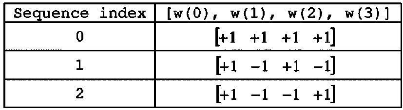
PUCCH 포맷 1a/1b에 있어서 BPSK 또는 QPSK 변조 방식을 이용하여 변조된 심볼은 길이 12 의 CAZAC 시퀀스로 승산(multiply)된다. 예를 들어, 변조 심볼 d(0)에 길이 N 의 CAZAC 시퀀스 r(n) (n=0, 1, 2, ..., N-1) 가 승산된 결과는 y(0), y(1), y(2), ..., y(N-1) 이 된다. y(0), ..., y(N-1) 심볼들을 심볼 블록(block of symbol)이라고 칭할 수 있다. 변조 심볼에 CAZAC 시퀀스를 승산한 후에, 직교 시퀀스를 이용한 블록-단위(block-wise) 확산이 적용된다. In the PUCCH format 1a / 1b, a symbol modulated using a BPSK or QPSK modulation scheme is multiply multiplied by a CAZAC sequence having a length of 12. For example, the result of multiplying modulation symbol d (0) by length CAZAC sequence r (n) (n = 0, 1, 2, ..., N-1) is y (0), y (1). ), y (2), ..., y (N-1). The y (0), ..., y (N-1) symbols may be referred to as a block of symbols. After multiplying the CAZAC sequence by the modulation symbol, block-wise spreading using an orthogonal sequence is applied.
일반 ACK/NACK 정보에 대해서는 길이 4의 하다마드(Hadamard) 시퀀스가 사용되고, 짧은(shortened) ACK/NACK 정보 및 참조신호(Reference Signal)에 대해서는 길이 3의 DFT(Discrete Fourier Transform) 시퀀스가 사용된다. 확장된 CP의 경우의 참조신호에 대해서는 길이 2의 하다마드 시퀀스가 사용된다. A Hadamard sequence of length 4 is used for general ACK / NACK information, and a Discrete Fourier Transform (DFT) sequence of length 3 is used for shortened ACK / NACK information and a reference signal. A Hadamard sequence of length 2 is used for the reference signal in the case of an extended CP.
도 7은 일반 CP의 경우에 ACK/NACK 채널의 구조를 나타낸다. 도 7에서는 CQI 없이 HARQ ACK/NACK 전송을 위한 PUCCH 채널 구조를 예시적으로 나타낸다. 하나의 슬롯에 포함되는 7 개의 SC-FDMA 심볼 중 중간 부분의 3개의 연속되는 SC-FDMA 심볼에는 참조신호(RS)가 실리고, 나머지 4 개의 SC-FDMA 심볼에는 ACK/NACK 신호가 실린다. 한편, 확장된 CP 의 경우에는 중간의 2 개의 연속되는 심볼에 RS 가 실릴 수 있다. RS에 사용되는 심볼의 개수 및 위치는 제어채널에 따라 달라질 수 있으며 이와 연관된 ACK/NACK 신호에 사용되는 심볼의 개수 및 위치도 그에 따라 변경될 수 있다. 7 shows a structure of an ACK / NACK channel in case of a normal CP. 7 exemplarily shows a PUCCH channel structure for HARQ ACK / NACK transmission without CQI. A reference signal RS is carried on three consecutive SC-FDMA symbols in the middle of seven SC-FDMA symbols included in one slot, and an ACK / NACK signal is carried on the remaining four SC-FDMA symbols. Meanwhile, in the case of an extended CP, RS may be carried on two consecutive symbols in the middle. The number and position of symbols used for the RS may vary depending on the control channel, and the number and position of symbols used for the ACK / NACK signal associated therewith may also be changed accordingly.
1 비트 및 2 비트의 확인응답 정보(스크램블링되지 않은 상태)는 각각 BPSK 및 QPSK 변조 기법을 사용하여 하나의 HARQ ACK/NACK 변조 심볼로 표현될 수 있다. 긍정확인응답(ACK)은 '1' 로 인코딩될 수 있고, 부정확인응답(NACK)은 '0'으로 인코딩될 수 있다. 1 bit and 2 bit acknowledgment information (unscrambled state) may be represented by one HARQ ACK / NACK modulation symbol using BPSK and QPSK modulation techniques, respectively. The acknowledgment (ACK) may be encoded as '1', and the negative acknowledgment (NACK) may be encoded as '0'.
할당되는 대역 내에서 제어신호를 전송할 때, 다중화 용량을 높이기 위해 2 차원 확산이 적용된다. 즉, 다중화할 수 있는 단말 수 또는 제어 채널의 수를 높이기 위해 주파수 영역 확산과 시간 영역 확산을 동시에 적용한다. ACK/NACK 신호를 주파수 영역에서 확산시키기 위해 주파수 영역 시퀀스를 기본 시퀀스로 사용한다. 주파수 영역 시퀀스로는 CAZAC 시퀀스 중 하나인 Zadoff-Chu (ZC) 시퀀스를 사용할 수 있다. 예를 들어, 기본 시퀀스인 ZC 시퀀스에 서로 다른 순환 시프트(Cyclic Shift; CS)가 적용됨으로써, 서로 다른 단말 또는 서로 다른 제어 채널의 다중화가 적용될 수 있다. HARQ ACK/NACK 전송을 위한 PUCCH RB 들을 위한 SC-FDMA 심볼에서 지원되는 CS 자원의 개수는 셀-특정 상위-계층 시그널링 파라미터(
Figure PCTKR2012001891-appb-I000036
)에 의해서 설정되며,
Figure PCTKR2012001891-appb-I000037
∈{1, 2, 3} 은 각각 12, 6 또는 4 시프트를 나타낸다.
When transmitting control signals in the allocated band, two-dimensional spreading is applied to increase the multiplexing capacity. That is, frequency domain spreading and time domain spreading are simultaneously applied to increase the number of terminals or control channels that can be multiplexed. In order to spread the ACK / NACK signal in the frequency domain, a frequency domain sequence is used as the base sequence. As the frequency domain sequence, one of the CAZAC sequences may be a Zadoff-Chu (ZC) sequence. For example, different cyclic shifts (CSs) are applied to a ZC sequence, which is a basic sequence, so that multiplexing of different terminals or different control channels may be applied. The number of CS resources supported in an SC-FDMA symbol for PUCCH RBs for HARQ ACK / NACK transmission is determined by a cell-specific high-layer signaling parameter (
Figure PCTKR2012001891-appb-I000036
),
Figure PCTKR2012001891-appb-I000037
∈ {1, 2, 3} represents 12, 6 or 4 shift, respectively.
주파수 영역 확산된 ACK/NACK 신호는 직교 확산(spreading) 코드를 사용하여 시간 영역에서 확산된다. 직교 확산 코드로는 월시-하다마드(Walsh-Hadamard) 시퀀스 또는 DFT 시퀀스가 사용될 수 있다. 예를 들어, ACK/NACK 신호는 4 심볼에 대해 길이 4의 직교 시퀀스(w0, w1, w2, w3)를 이용하여 확산될 수 있다. 또한, RS도 길이 3 또는 길이 2의 직교 시퀀스를 통해 확산시킨다. 이를 직교 커버링(Orthogonal Covering; OC)이라 한다. The frequency domain spread ACK / NACK signal is spread in the time domain using an orthogonal spreading code. As the orthogonal spreading code, a Walsh-Hadamard sequence or a DFT sequence may be used. For example, the ACK / NACK signal may be spread using orthogonal sequences w0, w1, w2, and w3 of length 4 for four symbols. RS is also spread through an orthogonal sequence of length 3 or length 2. This is called orthogonal covering (OC).
전술한 바와 같은 주파수 영역에서의 CS 자원 및 시간 영역에서의 OC 자원을 이용해서 다수의 단말들이 코드분할다중화(Code Division Multiplex; CDM) 방식으로 다중화될 수 있다. 즉, 동일한 PUCCH RB 상에서 많은 개수의 단말들의 ACK/NACK 정보 및 RS 가 다중화될 수 있다. A plurality of terminals may be multiplexed using a Code Division Multiplex (CDM) scheme using the CS resource in the frequency domain and the OC resource in the time domain as described above. That is, ACK / NACK information and RS of a large number of terminals may be multiplexed on the same PUCCH RB.
이와 같은 시간 영역 확산 CDM 에 대해서, ACK/NACK 정보에 대해서 지원되는 확산 코드들의 개수는 RS 심볼들의 개수에 의해서 제한된다. 즉, RS 전송 SC-FDMA 심볼들의 개수는 ACK/NACK 정보 전송 SC-FDMA 심볼들의 개수보다 적기 때문에, RS 의 다중화 용량(capacity)이 ACK/NACK 정보의 다중화 용량에 비하여 적게 된다. 예를 들어, 일반 CP 의 경우에 4 개의 심볼에서 ACK/NACK 정보가 전송될 수 있는데, ACK/NACK 정보를 위하여 4 개가 아닌 3 개의 직교 확산 코드가 사용되며, 이는 RS 전송 심볼의 개수가 3 개로 제한되어 RS 를 위하여 3 개의 직교 확산 코드만이 사용될 수 있기 때문이다. For this time domain spreading CDM, the number of spreading codes supported for ACK / NACK information is limited by the number of RS symbols. That is, since the number of RS transmission SC-FDMA symbols is smaller than the number of ACK / NACK information transmission SC-FDMA symbols, the multiplexing capacity of the RS is smaller than that of the ACK / NACK information. For example, in case of a normal CP, ACK / NACK information may be transmitted in four symbols. For the ACK / NACK information, three orthogonal spreading codes are used instead of four, which means that the number of RS transmission symbols is three. This is because only three orthogonal spreading codes can be used for the RS.
ACK/NACK 정보의 확산에 이용되는 직교 시퀀스의 일례는 표 3 및 표 4와 같다. 표 3은 길이 4 심볼에 대한 시퀀스를 나타내고, 표 4는 길이 3 심볼에 대한 시퀀스를 나타낸다. 길이 4 심볼에 대한 시퀀스는 일반적인 서브프레임 구성의 PUCCH 포맷 1/1a/1b에서 이용된다. 서브프레임 구성에 있어서 두 번째 슬롯의 마지막 심볼에서 SRS(Sounding Reference Signal)이 전송되는 등의 경우를 고려하여, 첫 번째 슬롯에서는 길이 4 심볼에 대한 시퀀스가 적용되고, 두 번째 슬롯에서는 길이 3 심볼에 대한 시퀀스의 짧은(shortened) PUCCH 포맷 1/1a/1b이 적용될 수 있다. Examples of orthogonal sequences used for spreading ACK / NACK information are shown in Tables 3 and 4. Table 3 shows the sequences for length 4 symbols and Table 4 shows the sequences for length 3 symbols. The sequence for the length 4 symbol is used in the PUCCH format 1 / 1a / 1b of the general subframe configuration. In the subframe configuration, a sequence of 4 symbols in length is applied in the first slot and 3 symbols in length in the second slot, taking into account a case in which a Sounding Reference Signal (SRS) is transmitted in the last symbol of the second slot. The shortened PUCCH format 1 / 1a / 1b of the sequence may be applied.
표 3
Figure PCTKR2012001891-appb-T000003
TABLE 3
Figure PCTKR2012001891-appb-T000003
표 4
Figure PCTKR2012001891-appb-T000004
Table 4
Figure PCTKR2012001891-appb-T000004
한편, ACK/NACK 채널의 RS의 확산에 사용되는 직교 시퀀스의 일례는 표 5와 같다. Meanwhile, an example of an orthogonal sequence used for spreading RS of an ACK / NACK channel is shown in Table 5.
표 5
Figure PCTKR2012001891-appb-T000005
Table 5
Figure PCTKR2012001891-appb-T000005
일반 CP 의 서브프레임에서 하나의 슬롯에서 3 개의 심볼이 RS 전송을 위해서 사용되고 4 개의 심볼이 ACK/NACK 정보 전송을 위해서 사용되는 경우에, 예를 들어, 주파수 영역에서 6 개의 순환시프트(CS) 및 시간 영역에서 3 개의 직교커버(OC) 자원을 사용할 수 있다면, 총 18 개의 상이한 단말로부터의 HARQ 확인응답이 하나의 PUCCH RB 내에서 다중화될 수 있다. 만약, 확장된 CP 의 서브프레임에서 하나의 슬롯에서 2 개의 심볼이 RS 전송을 위해서 사용되고 4 개의 심볼이 ACK/NACK 정보 전송을 위해서 사용되는 경우에, 예를 들어, 주파수 영역에서 6 개의 순환시프트(CS) 및 시간 영역에서 2 개의 직교커버(OC) 자원을 사용할 수 있다면, 총 12 개의 상이한 단말로부터의 HARQ 확인응답이 하나의 PUCCH RB 내에서 다중화될 수 있다. In the case where three symbols in one slot are used for RS transmission and four symbols are used for ACK / NACK information transmission in a subframe of a general CP, for example, six cyclic shifts (CS) and If three orthogonal cover (OC) resources are available in the time domain, HARQ acknowledgments from a total of 18 different terminals can be multiplexed within one PUCCH RB. If two symbols in one slot are used for RS transmission and four symbols are used for ACK / NACK information transmission in a subframe of an extended CP, for example, six cyclic shifts in the frequency domain ( If two orthogonal cover (OC) resources can be used in the CS) and the time domain, HARQ acknowledgments from a total of 12 different terminals can be multiplexed within one PUCCH RB.
다음으로, PUCCH 포맷 1에 대하여 설명한다. 스케줄링 요청(SR)은 단말이 스케줄링되기를 요청하거나 또는 요청하지 않는 방식으로 전송된다. SR 채널은 PUCCH 포맷 1a/1b 에서의 ACK/NACK 채널 구조를 재사용하고, ACK/NACK 채널 설계에 기초하여 OOK(On-Off Keying) 방식으로 구성된다. SR 채널에서는 참조신호가 전송되지 않는다. 따라서, 일반 CP 의 경우에는 길이 7 의 시퀀스가 이용되고, 확장된 CP 의 경우에는 길이 6 의 시퀀스가 이용된다. SR 및 ACK/NACK 에 대하여 상이한 순환 시프트 또는 직교 커버가 할당될 수 있다. 즉, 긍정(positive) SR 전송을 위해 단말은 SR용으로 할당된 자원을 통해 HARQ ACK/NACK을 전송한다. 부정(negative) SR 전송을 위해서는 단말은 ACK/NACK용으로 할당된 자원을 통해 HARQ ACK/NACK을 전송한다.Next, PUCCH format 1 will be described. The scheduling request SR is transmitted in such a manner that the terminal requests or does not request to be scheduled. The SR channel reuses the ACK / NACK channel structure in PUCCH formats 1a / 1b and is configured in an OOK (On-Off Keying) scheme based on the ACK / NACK channel design. Reference signals are not transmitted in the SR channel. Therefore, a sequence of length 7 is used for a general CP, and a sequence of length 6 is used for an extended CP. Different cyclic shifts or orthogonal covers may be assigned for SR and ACK / NACK. That is, for positive SR transmission, the UE transmits HARQ ACK / NACK through resources allocated for SR. In order to transmit a negative SR, the UE transmits HARQ ACK / NACK through a resource allocated for ACK / NACK.
다음으로, PUCCH 포맷 2/2a/2b에 대하여 설명한다. PUCCH 포맷 2/2a/2b는 채널 측정 피드백(CQI, PMI, RI)을 전송하기 위한 제어 채널이다. Next, the PUCCH format 2 / 2a / 2b will be described. PUCCH format 2 / 2a / 2b is a control channel for transmitting channel measurement feedback (CQI, PMI, RI).
채널측정피드백(이하에서는, 통칭하여 CQI 정보라고 표현함)의 보고 주기 및 측정 대상이 되는 주파수 단위(또는 주파수 해상도(resolution))는 기지국에 의하여 제어될 수 있다. 시간 영역에서 주기적 및 비주기적 CQI 보고가 지원될 수 있다. PUCCH 포맷 2 는 주기적 보고에만 사용되고, 비주기적 보고를 위해서는 PUSCH 가 사용될 수 있다. 비주기적 보고의 경우에 기지국은 단말에게 상향링크 데이터 전송을 위하여 스케줄링된 자원에 개별 CQI 보고를 실어서 전송할 것을 지시할 수 있다. The reporting period of the channel measurement feedback (hereinafter, collectively referred to as CQI information) and the frequency unit (or frequency resolution) to be measured may be controlled by the base station. Periodic and aperiodic CQI reporting can be supported in the time domain. PUCCH format 2 may be used only for periodic reporting and PUSCH may be used for aperiodic reporting. In the case of aperiodic reporting, the base station may instruct the terminal to transmit an individual CQI report on a resource scheduled for uplink data transmission.
도 8은 일반 CP의 경우에 CQI 채널의 구조를 나타낸다. 하나의 슬롯의 SC-FDMA 심볼 0 내지 6 중에서, SC-FDMA 심볼 1 및 5 (2 번째 및 6 번째 심볼)는 복조참조신호(Demodulation Reference Signal; DMRS) 전송에 사용되고, 나머지 SC-FDMA 심볼에서 CQI 정보가 전송될 수 있다. 한편, 확장된 CP 의 경우에는 하나의 SC-FDMA 심볼 (SC-FDMA 심볼 3) 이 DMRS 전송에 사용된다. 8 shows a structure of a CQI channel in the case of a normal CP. Of the SC-FDMA symbols 0 to 6 of one slot, SC-FDMA symbols 1 and 5 (second and sixth symbols) are used for demodulation reference signal (DMRS) transmission, and CQI in the remaining SC-FDMA symbols. Information can be transmitted. Meanwhile, in the case of an extended CP, one SC-FDMA symbol (SC-FDMA symbol 3) is used for DMRS transmission.
PUCCH 포맷 2/2a/2b 에서는 CAZAC 시퀀스에 의한 변조를 지원하고, QPSK 변조된 심볼이 길이 12 의 CAZAC 시퀀스로 승산된다. 시퀀스의 순환 시프트(CS)는 심볼 및 슬롯 간에 변경된다. DMRS에 대해서 직교 커버링이 사용된다. In the PUCCH format 2 / 2a / 2b, modulation by a CAZAC sequence is supported, and a QPSK modulated symbol is multiplied by a length 12 CAZAC sequence. The cyclic shift (CS) of the sequence is changed between symbol and slot. Orthogonal covering is used for DMRS.
하나의 슬롯에 포함되는 7 개의 SC-FDMA 심볼 중 3개의 SC-FDMA 심볼 간격만큼 떨어진 2개의 SC-FDMA 심볼에는 참조신호(DMRS)가 실리고, 나머지 5개의 SC-FDMA 심볼에는 CQI 정보가 실린다. 한 슬롯 안에 두 개의 RS가 사용된 것은 고속 단말을 지원하기 위해서이다. 또한, 각 단말은 순환 시프트(CS) 시퀀스를 사용하여 구분된다. CQI 정보 심볼들은 SC-FDMA 심볼 전체에 변조되어 전달되고, SC-FDMA 심볼은 하나의 시퀀스로 구성되어 있다. 즉, 단말은 각 시퀀스로 CQI를 변조해서 전송한다.Reference signal (DMRS) is carried on two SC-FDMA symbols spaced by three SC-FDMA symbol intervals among seven SC-FDMA symbols included in one slot, and CQI information is carried on the remaining five SC-FDMA symbols. Two RSs are used in one slot to support a high speed terminal. In addition, each terminal is distinguished using a cyclic shift (CS) sequence. The CQI information symbols are modulated and transmitted throughout the SC-FDMA symbol, and the SC-FDMA symbol is composed of one sequence. That is, the terminal modulates and transmits the CQI in each sequence.
하나의 TTI에 전송할 수 있는 심볼 수는 10개이고, CQI 정보의 변조는 QPSK까지 정해져 있다. SC-FDMA 심볼에 대해 QPSK 매핑을 사용하는 경우 2비트의 CQI 값이 실릴 수 있으므로, 한 슬롯에 10비트의 CQI 값을 실을 수 있다. 따라서, 한 서브프레임에 최대 20비트의 CQI 값을 실을 수 있다. CQI 정보를 주파수 영역에서 확산시키기 위해 주파수 영역 확산 부호를 사용한다. The number of symbols that can be transmitted in one TTI is 10, and modulation of CQI information is determined up to QPSK. When QPSK mapping is used for an SC-FDMA symbol, a 2-bit CQI value may be carried, and thus a 10-bit CQI value may be loaded in one slot. Therefore, a CQI value of up to 20 bits can be loaded in one subframe. A frequency domain spread code is used to spread the CQI information in the frequency domain.
주파수 영역 확산 부호로는 길이-12 의 CAZAC 시퀀스(예를 들어, ZC 시퀀스)를 사용할 수 있다. 각 제어채널은 서로 다른 순환 시프트(cyclic shift) 값을 갖는 CAZAC 시퀀스를 적용하여 구분될 수 있다. 주파수 영역 확산된 CQI 정보에 IFFT가 수행된다. As the frequency domain spreading code, a length-12 CAZAC sequence (eg, a ZC sequence) may be used. Each control channel may be distinguished by applying a CAZAC sequence having a different cyclic shift value. IFFT is performed on the frequency domain spread CQI information.
12 개의 동등한 간격을 가진 순환 시프트에 의해서 12 개의 상이한 단말들이 동일한 PUCCH RB 상에서 직교 다중화될 수 있다. 일반 CP 경우에 SC-FDMA 심볼 1 및 5 상의 (확장된 CP 경우에 SC-FDMA 심볼 3 상의) DMRS 시퀀스는 주파수 영역 상의 CQI 신호 시퀀스와 유사하지만 CQI 정보와 같은 변조가 적용되지는 않는다. 단말은 PUCCH 자원 인덱스(
Figure PCTKR2012001891-appb-I000038
)로 지시되는 PUCCH 자원 상에서 주기적으로 상이한 CQI, PMI 및 RI 타입을 보고하도록 상위 계층 시그널링에 의하여 반-정적으로(semi-statically) 설정될 수 있다. 여기서, PUCCH 자원 인덱스(
Figure PCTKR2012001891-appb-I000039
)는 PUCCH 포맷 2/2a/2b 전송에 사용되는 PUCCH 영역 및 사용될 순환시프트(CS) 값을 지시하는 정보이다.
12 different terminals may be orthogonally multiplexed on the same PUCCH RB by means of 12 equally spaced cyclic shifts. The DMRS sequence on SC-FDMA symbol 1 and 5 (on SC-FDMA symbol 3 in extended CP case) in the general CP case is similar to the CQI signal sequence on the frequency domain but no modulation such as CQI information is applied. UE is a PUCCH resource index (
Figure PCTKR2012001891-appb-I000038
May be semi-statically configured by higher layer signaling to periodically report different CQI, PMI, and RI types on the PUCCH resource indicated by h). Where the PUCCH resource index (
Figure PCTKR2012001891-appb-I000039
) Is information indicating a PUCCH region used for PUCCH format 2 / 2a / 2b transmission and a cyclic shift (CS) value to be used.
다음으로 개선된-PUCCH(e-PUCCH) 포맷에 대하여 설명한다. e-PUCCH는 LTE-A 시스템의 PUCCH 포맷 3에 대응할 수 있다. PUCCH 포맷 3을 이용한 ACK/NACK 전송에는 블록 확산(block spreading) 기법이 적용될 수 있다. Next, the enhanced-PUCCH (e-PUCCH) format will be described. The e-PUCCH may correspond to PUCCH format 3 of the LTE-A system. Block spreading can be applied to ACK / NACK transmission using PUCCH format 3.
블록 확산 기법은, 기존의 PUCCH 포맷 1 계열 또는 2 계열과는 달리, 제어 신호 전송을 SC-FDMA 방식을 이용하여 변조하는 방식이다. 도 13에서 나타내는 바와 같이, 심볼 시퀀스가 OCC(Orthogonal Cover Code)를 이용하여 시간 영역(domain) 상에서 확산되어 전송될 수 있다. OCC를 이용함으로써 동일한 RB 상에 복수개의 단말들의 제어 신호들이 다중화될 수 있다. 전술한 PUCCH 포맷 2의 경우에는 하나의 심볼 시퀀스가 시간 영역에 걸쳐서 전송되고 CAZAC 시퀀스의 CS(cyclic shift)를 이용하여 복수개의 단말들의 제어 신호들이 다중화되는 반면, 블록 확산 기반 PUCCH 포맷(예를 들어, PUCCH 포맷 3)의 경우에는 하나의 심볼 시퀀스가 주파수 영역에 걸쳐서 전송되고, OCC를 이용한 시간 영역 확산을 이용하여 복수개의 단말들의 제어 신호들이 다중화된다. Unlike the conventional PUCCH format 1 series or 2 series, the block spreading scheme modulates control signal transmission using the SC-FDMA scheme. As shown in FIG. 13, a symbol sequence may be spread and transmitted on a time domain using an orthogonal cover code (OCC). By using the OCC, control signals of a plurality of terminals may be multiplexed on the same RB. In the case of the above-described PUCCH format 2, one symbol sequence is transmitted over a time domain and control signals of a plurality of terminals are multiplexed using a cyclic shift (CS) of a CAZAC sequence, whereas a block spread based PUCCH format (for example, In the case of PUCCH format 3), one symbol sequence is transmitted over a frequency domain, and control signals of a plurality of terminals are multiplexed using time-domain spreading using OCC.
도 9(a)에서는 1 슬롯 동안에 하나의 심볼 시퀀스에 길이=4 (또는 확산 인자(spreading factor; SF)=4)의 OCC를 이용하여 4 개의 SC-FDMA 심볼(즉, 데이터 부분)을 생성하여 전송하는 예시를 나타낸다. 이 경우, 1 슬롯 동안 3 개의 RS 심볼(즉, RS 부분)이 사용될 수 있다. In FIG. 9 (a), four SC-FDMA symbols (that is, data portions) are generated by using an OCC having a length = 4 (or spreading factor (SF) = 4) in one symbol sequence for one slot. An example of transmission is shown. In this case, three RS symbols (ie, RS portions) may be used during one slot.
또는, 도 9(b)에서는 1 슬롯 동안에 하나의 심볼 시퀀스에 길이=5 (또는 SF=5)의 OCC를 이용하여 5 개의 SC-FDMA 심볼(즉, 데이터 부분)을 생성하여 전송하는 예시를 나타낸다. 이 경우, 1 슬롯 동안 2 개의 RS 심볼이 사용될 수 있다. Alternatively, FIG. 9 (b) shows an example of generating and transmitting five SC-FDMA symbols (i.e., data portions) by using an OCC having a length = 5 (or SF = 5) in one symbol sequence during one slot. . In this case, two RS symbols may be used for one slot.
도 9의 예시에서, RS 심볼은 특정 순환 시프트 값이 적용된 CAZAC 시퀀스로부터 생성될 수 있으며, 복수개의 RS 심볼에 걸쳐 소정의 OCC가 적용된 (또는 곱해진) 형태로 전송될 수 있다. 또한, 도 13의 예시에서 각각의 OFDM 심볼(또는 SC-FDMA 심볼) 별로 12 개의 변조 심볼이 사용되고, 각각의 변조 심볼은 QPSK에 의해 생성되는 것으로 가정하면, 하나의 슬롯에서 전송할 수 있는 최대 비트 수는 12x2=24 비트가 된다. 따라서, 2개의 슬롯으로 전송할 수 있는 비트수는 총 48비트가 된다. 이와 같이 블록 확산 방식의 PUCCH 채널 구조를 사용하는 경우 기존의 PUCCH 포맷 1계열 및 2 계열에 비하여 확장된 크기의 제어 정보의 전송이 가능해진다. In the example of FIG. 9, an RS symbol may be generated from a CAZAC sequence to which a specific cyclic shift value is applied, and may be transmitted in a form in which a predetermined OCC is applied (or multiplied) over a plurality of RS symbols. In addition, in the example of FIG. 13, assuming that 12 modulation symbols are used for each OFDM symbol (or SC-FDMA symbol), and each modulation symbol is generated by QPSK, the maximum number of bits that can be transmitted in one slot Becomes 12x2 = 24 bits. Therefore, the number of bits that can be transmitted in two slots is a total of 48 bits. As described above, when the block spread type PUCCH channel structure is used, control information having an extended size can be transmitted as compared to the PUCCH format 1 series and 2 series.
반송파 병합Carrier merge
반송파 병합을 설명하기에 앞서 LTE-A에서 무선자원을 관리하기 위해 도입된 셀(Cell)의 개념에 대해 먼저 설명한다. 셀은 하향링크 자원과 상향링크 자원의 조합으로 이해될 수 있다. 여기서 상향링크 자원은 필수 요소는 아니며 따라서 셀은 하향링크 자원 단독 또는 하향링크 자원과 상향링크 자원으로 이루어질 수 있다. 다만, 이는 현재 LTE-A 릴리즈 10에서의 정의이며 반대의 경우, 즉 셀이 상향링크 자원 단독으로 이루어지는 것도 가능하다. 하향링크 자원은 하향링크 구성반송파(Downlink component carrier, DL CC)로 상향링크 자원은 상향링크 구성반송파(Uplink component carrier, UL CC)로 지칭될 수 있다. DL CC 및 UL CC는 반송파 주파수(carrier frequency)로 표현될 수 있으며, 반송파 주파수는 해당 셀에서의 중심주파수(center frequency)를 의미한다.Prior to describing carrier aggregation, a concept of a cell introduced to manage radio resources in LTE-A will be described first. A cell may be understood as a combination of downlink resources and uplink resources. Here, the uplink resource is not an essential element, and thus, the cell may be composed of only the downlink resource or the downlink resource and the uplink resource. However, this is the definition in the current LTE-A Release 10 and vice versa, that is, the cell may be made up of uplink resources alone. The downlink resource may be referred to as a downlink component carrier (DL CC) and the uplink resource may be referred to as an uplink component carrier (UL CC). The DL CC and the UL CC may be represented by a carrier frequency, and the carrier frequency means a center frequency in a corresponding cell.
셀은 프라이머리 주파수(primary frequency)에서 동작하는 프라이머리 셀(primary cell, PCell)과 세컨더리 주파수(secondary frequency)에서 동작하는 세컨더리 셀(secondary cell, SCell)로 분류될 수 있다. PCell과 SCell은 서빙 셀(serving cell)로 통칭될 수 있다. PCell은 단말이 초기 연결 설정(initial connection establishment) 과정을 수행하거나 연결 재설정 과정 또는 핸드오버 과정에서 지시된 셀이 PCell이 될 수 있다. 즉, PCell은 후술할 반송파 병합 환경에서 제어관련 중심이 되는 셀로 이해될 수 있다. 단말은 자신의 PCell에서 PUCCH를 할당 받고 전송할 수 있다. SCell은 RRC(Radio Resource Control) 연결 설정이 이루어진 이후 구성 가능하고 추가적인 무선 자원을 제공하는데 사용될 수 있다. 반송파 병합 환경에서 PCell을 제외한 나머지 서빙 셀을 SCell로 볼 수 있다. RRC_CONNECTED 상태에 있지만 반송파 병합이 설정되지 않았거나 반송파 병합을 지원하지 않는 단말의 경우, PCell로만 구성된 서빙 셀이 단 하나 존재한다. 반면, RRC_CONNECTED 상태에 있고 반송파 병합이 설정된 단말의 경우, 하나 이상의 서빙 셀이 존재하고, 전체 서빙 셀에는 PCell과 전체 SCell이 포함된다. 반송파 병합을 지원하는 단말을 위해 네트워크는 초기 보안 활성화(initial security activation) 과정이 개시된 이후, 연결 설정 과정에서 초기에 구성되는 PCell에 부가하여 하나 이상의 SCell을 구성할 수 있다.A cell may be classified into a primary cell (PCell) operating at a primary frequency and a secondary cell (SCell) operating at a secondary frequency. PCell and SCell may be collectively referred to as a serving cell. In the PCell, the terminal may perform an initial connection establishment (initial connection establishment) process, or the cell indicated in the connection reset process or handover process may be a PCell. That is, the PCell may be understood as a cell that is the center of control in a carrier aggregation environment to be described later. The UE may receive and transmit a PUCCH in its PCell. The SCell is configurable after the Radio Resource Control (RRC) connection is established and can be used to provide additional radio resources. In the carrier aggregation environment, the remaining serving cells except the PCell may be viewed as SCells. In the RRC_CONNECTED state, but the UE is not configured carrier aggregation or does not support carrier aggregation, there is only one serving cell consisting of a PCell. On the other hand, in the case of a terminal in the RRC_CONNECTED state and the carrier aggregation is configured, one or more serving cells exist, and all the serving cells include the PCell and the entire SCell. For a terminal supporting carrier aggregation, after the initial security activation process is initiated, the network may configure one or more SCells in addition to the PCell initially configured in the connection establishment process.
이하, 도 10을 참조하여 반송파 병합에 대해 설명한다. 반송파 병합은 높은 고속 전송률에 대한 요구에 부합하기 위해 보다 넓은 대역을 사용할 수 있도록 도입된 기술이다. 반송파 병합은 반송파 주파수가 서로 다른 2개 이상의 구성반송파(component carrier, CC)들의 집합(aggregation)으로 정의될 수 있다. 도 10(a)는 기존 LTE 시스템에서 하나의 CC를 사용하는 경우의 서브프레임을 나타내고, 도 10(b)는 반송파 병합이 사용되는 경우의 서브프레임을 나타낸다. 도 10(b)에는 예시적으로 20MHz의 CC 3개가 사용되어 총 60MHz의 대역폭을 지원하는 것을 도시하고 있다. 여기서 각 CC는 연속적일 수도 있고, 또한 비 연속적일 수도 있다.Hereinafter, carrier aggregation will be described with reference to FIG. 10. Carrier aggregation is a technology introduced to use a wider band in order to meet the demand for high speed data rates. Carrier aggregation may be defined as an aggregation of two or more component carriers (CCs) having different carrier frequencies. FIG. 10 (a) shows a subframe when one CC is used in an existing LTE system, and FIG. 10 (b) shows a subframe when carrier aggregation is used. In FIG. 10B, three CCs of 20 MHz are used to support a total bandwidth of 60 MHz. Here, each CC may be continuous or may be non-continuous.
단말은 하향링크 데이터를 복수개의 DL CC를 통해 동시에 수신하고 모니터할 수 있다. 각 DL CC와 UL CC 사이의 링키지(linkage)는 시스템 정보에 의해 지시될 수 있다. DL CC/UL CC 링크는 시스템에 고정되어 있거나 반-정적으로 구성될 수 있다. 또한, 시스템 전체 대역이 N개의 CC로 구성되더라도 특정 단말이 모니터링/수신할 수 있는 주파수 대역은 M(<N)개의 CC로 한정될 수 있다. 캐리어 병합에 대한 다양한 파라미터는 셀 특정(cell-specific), 단말 그룹 특정(UE group-specific) 또는 단말 특정(UE-specific) 방식으로 설정될 수 있다.The terminal may simultaneously receive and monitor downlink data through a plurality of DL CCs. The linkage between each DL CC and UL CC may be indicated by system information. The DL CC / UL CC link may be fixed in the system or configured semi-statically. In addition, even if the entire system band is composed of N CCs, the frequency band that a specific UE can monitor / receive may be limited to M (<N) CCs. Various parameters for carrier aggregation may be set in a cell-specific, UE group-specific or UE-specific manner.
도 11은 크로스-반송파 스케줄링을 설명하기 위한 도면이다. 크로스-반송파 스케줄링이란, 예를 들어, 복수의 서빙 셀 중 어느 하나의 DL CC의 제어영역에 다른 DL CC의 하향링크 스케줄링 할당 정보를 모두 포함하는 것, 또는 복수의 서빙 셀 중 어느 하나의 DL CC의 제어영역에 그 DL CC와 링크되어 있는 복수의 UL CC에 대한 상향링크 스케줄링 승인 정보를 모두 포함하는 것을 의미한다. 11 is a diagram for explaining cross-carrier scheduling. Cross-carrier scheduling means, for example, including all downlink scheduling allocation information of another DL CC in a control region of one DL CC among a plurality of serving cells, or a DL CC of any one of a plurality of serving cells. This means that the uplink scheduling grant information for the plurality of UL CCs linked with the DL CC is included in the control region of the UE.
먼저 반송파 지시자 필드(carrier indicator field, CIF)에 대해 설명한다. CIF는 앞서 설명된 바와 같이 PDCCH를 통해 전송되는 DCI 포맷에 포함되거나 또는 불포함 수 있으며, 포함된 경우 크로스 반송파 스케줄링이 적용된 것을 나타낸다. 크로스 반송파 스케줄링이 적용되지 않은 경우에는 하향링크 스케줄링 할당 정보는 현재 하향링크 스케줄링 할당 정보가 전송되는 DL CC상에서 유효하다. 또한 상향링크 스케줄링 승인은 하향링크 스케줄링 할당 정보가 전송되는 DL CC 와 링크된 하나의 UL CC에 대해 유효하다. First, a carrier indicator field (CIF) will be described. As described above, the CIF may be included or not included in the DCI format transmitted through the PDCCH, and when included, it indicates that the cross carrier scheduling is applied. When cross carrier scheduling is not applied, downlink scheduling allocation information is valid on a DL CC through which current downlink scheduling allocation information is transmitted. The uplink scheduling grant is also valid for one UL CC linked with the DL CC through which the downlink scheduling assignment information is transmitted.
크로스 반송파 스케줄링이 적용된 경우, CIF는 어느 하나의 DL CC에서 PDCCH를 통해 전송되는 하향링크 스케줄링 할당 정보에 관련된 CC를 지시한다. 예를 들어, 도 11을 참조하면 DL CC A 상의 제어 영역 내 PDCCH를 통해 DL CC B 및 DL CC C에 대한 하향링크 할당 정보, 즉 PDSCH 자원에 대한 정보가 전송된다. 단말은 DL CC A를 모니터링하여 CIF를 통해 PDSCH의 자원영역 및 해당 CC를 알 수 있다.When cross carrier scheduling is applied, the CIF indicates a CC related to downlink scheduling allocation information transmitted through a PDCCH in one DL CC. For example, referring to FIG. 11, downlink allocation information for DL CC B and DL CC C, that is, information about PDSCH resources, is transmitted through a PDCCH in a control region on DL CC A. The UE monitors the DL CC A to know the resource region of the PDSCH and the corresponding CC through the CIF.
PDCCH에 CIF가 포함되거나 또는 포함되지 않는지는 반-정적으로 설정될 수 있고, 상위 계층 시그널링에 의해서 단말-특정으로 활성화될 수 있다. Whether CIF is included or not included in the PDCCH may be set semi-statically and may be UE-specific activated by higher layer signaling.
CIF가 비활성화(disabled)된 경우에, 특정 DL CC 상의 PDCCH는 해당 동일한 DL CC 상의 PDSCH 자원을 할당하고, 특정 DL CC에 링크된 UL CC 상의 PUSCH 자원을 할당할 수 있다. 이 경우, 기존의 PDCCH 구조와 동일한 코딩 방식, CCE 기반 자원 매핑, DCI 포맷 등이 적용될 수 있다. When CIF is disabled, the PDCCH on a particular DL CC may allocate PDSCH resources on that same DL CC and allocate PUSCH resources on a UL CC linked to the particular DL CC. In this case, the same coding scheme, CCE-based resource mapping, DCI format, and the like as the existing PDCCH structure may be applied.
한편, CIF가 활성화(enabled)되는 경우에, 특정 DL CC 상의 PDCCH는 복수개의 병합된 CC들 중에서 CIF가 지시하는 하나의 DL/UL CC 상에서의 PDSCH/PUSCH 자원을 할당할 수 있다. 이 경우, 기존의 PDCCH DCI 포맷에 CIF가 추가적으로 정의될 수 있으며, 고정된 3 비트 길이의 필드로 정의되거나, CIF 위치가 DCI 포맷 크기에 무관하게 고정될 수도 있다. 이 경우에도, 기존의 PDCCH 구조와 동일한 코딩 방식, CCE 기반 자원 매핑, DCI 포맷 등이 적용될 수 있다. Meanwhile, when CIF is enabled, the PDCCH on a specific DL CC may allocate PDSCH / PUSCH resources on one DL / UL CC indicated by the CIF among a plurality of merged CCs. In this case, the CIF may be additionally defined in the existing PDCCH DCI format, may be defined as a fixed 3-bit field, or the CIF position may be fixed regardless of the DCI format size. In this case, the same coding scheme, CCE-based resource mapping, DCI format, and the like as the existing PDCCH structure may be applied.
CIF가 존재하는 경우에도, 기지국은 PDCCH를 모니터링할 DL CC 세트를 할당할 수 있다. 이에 따라, 단말의 블라인드 디코딩의 부담이 감소할 수 있다. PDCCH 모니터링 CC 세트는 전체 병합된 DL CC의 일부분이고 단말은 PDCCH의 검출/디코딩을 해당 CC 세트에서만 수행할 수 있다. 즉, 단말에 대해서 PDSCH/PUSCH를 스케줄링하기 위해서, 기지국은 PDCCH를 PDCCH 모니터링 CC 세트 상에서만 전송할 수 있다. PDCCH 모니터링 DL CC 세트는 단말-특정 또는 단말 그룹-특정 또는 셀-특정으로 설정될 수 있다. 예를 들어, 도 15의 예시에서와 같이 3 개의 DL CC가 병합되는 경우에, DL CC A 가 PDCCH 모니터링 DL CC로 설정될 수 있다. CIF가 비활성화되는 경우, 각각의 DL CC 상의 PDCCH는 DL CC A에서의 PDSCH만을 스케줄링할 수 있다. 한편, CIF가 활성화되면 DL CC A 상의 PDCCH는 DL CC A는 물론 다른 DL CC에서의 PDSCH 도 스케줄링할 수 있다. DL CC A가 PDCCH 모니터링 CC로 설정되는 설정되는 경우에는 DL CC B 및 DL CC C 에는 PDSCCH가 전송되지 않는다. Even if CIF exists, the base station can allocate a set of DL CC to monitor the PDCCH. Accordingly, the burden of blind decoding of the terminal can be reduced. The PDCCH monitoring CC set is a part of the total merged DL CCs and the UE may perform detection / decoding of the PDCCH only in the corresponding CC set. That is, in order to schedule PDSCH / PUSCH for the UE, the base station may transmit the PDCCH only on the PDCCH monitoring CC set. The PDCCH monitoring DL CC set may be configured as UE-specific or UE group-specific or cell-specific. For example, when three DL CCs are merged as in the example of FIG. 15, DL CC A may be set to the PDCCH monitoring DL CC. When CIF is deactivated, the PDCCH on each DL CC may only schedule PDSCH in DL CC A. On the other hand, when CIF is activated, the PDCCH on DL CC A may schedule not only DL CC A but also PDSCH on another DL CC. When DL CC A is set to PDCCH monitoring CC, PDSCCH is not transmitted to DL CC B and DL CC C.
ACK/NACK 전송ACK / NACK transmission
예를 들어, 전술한 바와 같은 반송파 병합이 적용되는 시스템에서, 단말은 복수개의 하향링크 반송파를 통해서 복수개의 PDSCH를 수신할 수 있고, 이러한 경우 단말은 각각의 데이터에 대한 ACK/NACK을 하나의 서브프레임에서 하나의 UL CC 상에서 전송하여야 하는 경우가 발생하게 된다. 하나의 서브프레임에서 복수개의 ACK/NACK을 PUCCH 포맷 1a/1b을 이용하여 전송하는 경우, 높은 전송 전력이 요구되며 상향링크 전송의 PAPR이 증가하게 되고 전송 전력 증폭기의 비효율적인 사용으로 인하여 단말의 기지국으로부터의 전송 가능 거리가 감소할 수 있다. 하나의 PUCCH를 통해서 복수개의 ACK/NACK을 전송하기 위해서는 ACK/NACK 번들링(bundling) 또는 ACK/NACK 다중화(multiplexing)가 적용될 수 있다. For example, in a system to which carrier aggregation as described above is applied, the terminal may receive a plurality of PDSCHs through a plurality of downlink carriers, and in this case, the terminal may perform ACK / NACK for each data in one sub-channel. There is a case where a transmission has to be performed on one UL CC in a frame. When transmitting a plurality of ACK / NACK in one subframe using the PUCCH format 1a / 1b, high transmission power is required, the PAPR of the uplink transmission is increased and the base station of the terminal due to inefficient use of the transmission power amplifier The transmittable distance from can be reduced. In order to transmit a plurality of ACK / NACK through one PUCCH, ACK / NACK bundling or ACK / NACK multiplexing may be applied.
또한, 반송파 병합의 적용에 따른 많은 개수의 하향링크 데이터 및/또는 TDD 시스템에서 복수개의 DL 서브프레임에서 전송된 많은 개수의 하향링크 데이터에 대한 ACK/NACK 정보가 하나의 서브프레임에서 PUCCH를 통해 전송되어야 하는 경우가 발생할 수 있다. 이러한 경우에서 전송되어야 할 ACK/NACK 비트가 ACK/NACK 번들링 또는 다중화로 지원가능한 개수보다 많은 경우에는, 위 방안들로는 올바르게 ACK/NACK 정보를 전송할 수 없게 된다. In addition, ACK / NACK information for a large number of downlink data and / or a large number of downlink data transmitted in a plurality of DL subframes in a TDD system according to carrier aggregation is transmitted through a PUCCH in one subframe. Cases may arise. In this case, if the number of ACK / NACK bits to be transmitted is larger than the number that can be supported by ACK / NACK bundling or multiplexing, the above methods cannot correctly transmit ACK / NACK information.
이하에서는, ACK/NACK 다중화 방안에 대하여 설명한다. Hereinafter, an ACK / NACK multiplexing scheme will be described.
ACK/NACK 다중화의 경우에, 복수개의 데이터 유닛에 대한 ACK/NACK 응답의 내용(contents)은 실제 ACK/NACK 전송에서 사용되는 ACK/NACK 유닛과 QPSK 변조된 심볼들 중의 하나의 조합(combination)에 의해서 식별될 수 있다. 예를 들어, 하나의 ACK/NACK 유닛이 2 비트 크기의 정보를 나르는 것으로 가정하고, 최대 2 개의 데이터 유닛을 수신하는 것을 가정한다. 여기서, 수신된 각각의 데이터 유닛에 대한 HARQ 확인응답은 하나의 ACK/NACK 비트에 의해서 표현되는 것으로 가정한다. 이러한 경우, 데이터를 전송한 송신단은 ACK/NACK 결과를 아래의 표 6에서 나타내는 바와 같이 식별할 수 있다. In the case of ACK / NACK multiplexing, the contents of the ACK / NACK response for a plurality of data units are in combination with one of the ACK / NACK unit and QPSK modulated symbols used in the actual ACK / NACK transmission. Can be identified. For example, it is assumed that one ACK / NACK unit carries two bits of information, and that a maximum of two data units are received. Here, it is assumed that the HARQ acknowledgment for each received data unit is represented by one ACK / NACK bit. In this case, the transmitting end that has transmitted the data can identify the ACK / NACK result as shown in Table 6 below.
표 6
Figure PCTKR2012001891-appb-T000006
Table 6
Figure PCTKR2012001891-appb-T000006
상기 표 6에서, HARQ-ACK(i) (i=0, 1) 는 데이터 유닛 i 에 대한 ACK/NACK 결과를 나타낸다. 전술한 바와 같이 최대 2 개의 데이터 유닛(데이터 유닛 0 및 데이터 유닛 1)이 수신되는 것을 가정하였으므로, 상기 표 6에서는 데이터 유닛 0 에 대한 ACK/NACK 결과는 HARQ-ACK(0)으로 표시하고, 데이터 유닛 1 에 대한 ACK/NACK 결과는 HARQ-ACK(1)로 표시한다. 상기 표 6에서, DTX(Discontinuous Transmission)는, HARQ-ACK(i)에 대응하는 데이터 유닛이 전송되지 않음을 나타내거나, 또는 수신단이 HARQ-ACK(i)에 대응하는 데이터 유닛의 존재를 검출하지 못하는 것을 나타낸다. 또한,
Figure PCTKR2012001891-appb-I000040
은 실제 ACK/NACK 전송에 사용되는 ACK/NACK 유닛을 나타낸다. 최대 2 개의 ACK/NACK 유닛이 존재하는 경우,
Figure PCTKR2012001891-appb-I000041
Figure PCTKR2012001891-appb-I000042
로 표현될 수 있다. 또한, b (0), b (1) 는 선택된 ACK/NACK 유닛에 의해서 전송되는 2 개의 비트를 나타낸다. ACK/NACK 유닛을 통해서 전송되는 변조 심볼은 b (0), b (1) 비트에 따라서 결정된다.
In Table 6, HARQ-ACK (i) (i = 0, 1) represents the ACK / NACK result for the data unit i. Since it is assumed that up to two data units (data unit 0 and data unit 1) are received as described above, in Table 6, the ACK / NACK result for data unit 0 is represented as HARQ-ACK (0), and data The ACK / NACK result for unit 1 is indicated by HARQ-ACK (1). In Table 6, DTX (Discontinuous Transmission) indicates that a data unit corresponding to HARQ-ACK (i) is not transmitted, or the receiving end does not detect the presence of a data unit corresponding to HARQ-ACK (i). It indicates that you cannot. Also,
Figure PCTKR2012001891-appb-I000040
Represents an ACK / NACK unit used for actual ACK / NACK transmission. If there are up to two ACK / NACK units,
Figure PCTKR2012001891-appb-I000041
And
Figure PCTKR2012001891-appb-I000042
It can be expressed as. In addition, b (0) and b (1) indicate two bits transmitted by the selected ACK / NACK unit. The modulation symbol transmitted through the ACK / NACK unit is determined according to the b (0) and b (1) bits.
예를 들어, 수신단이 2 개의 데이터 유닛을 성공적으로 수신 및 디코딩한 경우 (즉, 상기 표 5 의 ACK, ACK 의 경우), 수신단은 ACK/NACK 유닛
Figure PCTKR2012001891-appb-I000043
를 사용해서 2 개의 비트 (1, 1) 을 전송한다. 또는, 수신단이 2 개의 데이터 유닛을 수신하는 경우에, 제 1 데이터 유닛(즉, HARQ-ACK(0)에 대응하는 데이터 유닛 0)의 디코딩(또는 검출)에 실패하고 제 2 데이터 유닛(즉, HARQ-ACK(1)에 대응하는 데이터 유닛 1)의 디코딩에 성공하면 (즉, 상기 표 5 의 NACK/DTX, ACK 의 경우), 수신단은 ACK/NACK 유닛
Figure PCTKR2012001891-appb-I000044
을 사용해서 2 개의 비트 (0,0) 을 전송한다.
For example, if the receiving end has successfully received and decoded two data units (i.e., ACK and ACK of Table 5), the receiving end is an ACK / NACK unit.
Figure PCTKR2012001891-appb-I000043
To transmit two bits (1, 1). Or, when the receiving end receives two data units, the decoding (or detection) of the first data unit (ie, data unit 0 corresponding to HARQ-ACK (0)) fails and the second data unit (ie, If the decoding of the data unit 1 corresponding to the HARQ-ACK 1 is successful (i.e., in the case of NACK / DTX and ACK of Table 5 above), the receiving end is an ACK / NACK unit.
Figure PCTKR2012001891-appb-I000044
To transmit two bits (0,0).
이와 같이, ACK/NACK 유닛의 선택 및 전송되는 ACK/NACK 유닛의 실제 비트 내용의 조합(즉, 상기 표 5 에서
Figure PCTKR2012001891-appb-I000045
또는
Figure PCTKR2012001891-appb-I000046
중 하나를 선택하는 것과 b (0), b (1) 의 조합)을 실제 ACK/NACK 의 내용과 연계(link) 또는 매핑시킴으로써, 하나의 ACK/NACK 유닛을 이용해서 복수개의 데이터 유닛에 대한 ACK/NACK 정보를 전송할 수 있게 된다. 전술한 ACK/NACK 다중화의 원리를 그대로 확장하여, 2 보다 많은 개수의 데이터 유닛에 대한 ACK/NACK 다중화가 용이하게 구현될 수 있다.
As such, the combination of selection of the ACK / NACK unit and the actual bit contents of the transmitted ACK / NACK unit (i.e., in Table 5 above)
Figure PCTKR2012001891-appb-I000045
or
Figure PCTKR2012001891-appb-I000046
ACK for a plurality of data units using one ACK / NACK unit by linking or mapping one of the selection and a combination of b (0) and b (1) with the contents of the actual ACK / NACK. / NACK information can be transmitted. By extending the aforementioned principle of ACK / NACK multiplexing as it is, ACK / NACK multiplexing for more than 2 data units can be easily implemented.
이러한 ACK/NACK 다중화 방식에 있어서 기본적으로 모든 데이터 유닛에 대해서 적어도 하나의 ACK 이 존재하는 경우에는, NACK 과 DTX 가 구별되지 않을 수 있다 (즉, 상기 표 6에서 NACK/DTX 로 표현되는 바와 같이, NACK과 DTX가 결합(couple)될 수 있다). 왜냐하면, NACK 과 DTX 를 구분하여 표현하고자 하는 경우에 발생할 수 있는 모든 ACK/NACK 상태(즉, ACK/NACK 가설들(hypotheses))를, ACK/NACK 유닛과 QPSK 변조된 심볼의 조합만으로는 반영할 수 없기 때문이다. 한편, 모든 데이터 유닛에 대해서 ACK 이 존재하지 않는 경우(즉, 모든 데이터 유닛에 대해서 NACK 또는 DTX 만이 존재하는 경우)에는, HARQ-ACK(i)들 중에서 하나만이 확실히 NACK 인(즉, DTX과 구별되는 NACK) 것을 나타내는 하나의 확실한 NACK 의 경우가 정의될 수 있다. 이러한 경우, 하나의 확실한 NACK 에 해당하는 데이터 유닛에 대응하는 PUCCH 자원은 복수개의 ACK/NACK 들의 신호를 전송하기 위해 유보(reserved)될 수도 있다. In the ACK / NACK multiplexing scheme, if at least one ACK exists for all data units, NACK and DTX may not be distinguished (that is, represented as NACK / DTX in Table 6 above). NACK and DTX may be coupled). This is because all ACK / NACK states (that is, ACK / NACK hypotheses) that can occur when NACK and DTX are to be expressed separately can be reflected by a combination of an ACK / NACK unit and a QPSK modulated symbol. Because there is not. On the other hand, if no ACK exists for all data units (i.e., only NACK or DTX exists for all data units), only one of the HARQ-ACK (i) is definitely NACK (i.e. distinguished from DTX). One certain NACK case may be defined. In this case, the PUCCH resource corresponding to the data unit corresponding to one certain NACK may be reserved for transmitting signals of a plurality of ACK / NACKs.
D2D 통신D2D communication
전술한 바와 같은 무선 통신 시스템(예를 들어, 3GPP LTE 시스템 또는 3GPP LTE-A 시스템)에 D2D 통신이 도입되는 경우, D2D 통신을 수행하기 위한 구체적인 방안에 대하여 이하에서 설명한다. When D2D communication is introduced into the wireless communication system (for example, 3GPP LTE system or 3GPP LTE-A system) as described above, a detailed method for performing D2D communication will be described below.
도 12는 D2D 통신을 개념적으로 설명하기 위한 도면이다. 도 12(a)는 기존의 기지국 중심 통신 방식을 나타내는 것으로, UE1이 상향링크 상에서 기지국으로 데이터를 전송하고, UE1으로부터의 데이터를 기지국이 하향링크 상에서 UE2에게 전송할 수 있다. 12 is a diagram for conceptually explaining D2D communication. 12 (a) shows a conventional base station-centric communication scheme, where UE1 transmits data to a base station on uplink and base station transmits data from UE1 to UE2 on downlink.
도 12(b)는 D2D 통신의 일례로서 UE-to-UE 통신 방식을 나타내는 것으로, UE간의 데이터 교환이 기지국을 거치지 않고 수행될 수 있다. 이와 같이 장치들 간에 직접 설정되는 링크를 D2D 링크라고 칭할 수 있다. D2D 통신은 기존의 기지국 중심의 통신 방식에 비하여 지연(latency)이 줄어들고, 보다 적은 무선 자원을 필요로 하는 등의 장점을 가진다. 12 (b) illustrates a UE-to-UE communication scheme as an example of D2D communication, and data exchange between UEs may be performed without passing through a base station. As such, a link established directly between devices may be referred to as a D2D link. D2D communication has advantages such as reduced latency and less radio resources than conventional base station-oriented communication.
D2D 통신은 기지국을 거치지 않고 장치간(또는 단말간)의 통신을 지원하는 방식이지만, D2D 통신은 기존의 무선 통신 네트워크(예를 들어, 3GPP LTE 또는 3GPP LTE-A)의 자원을 재사용하여 수행되기 때문에 기존의 무선 통신 네트워크에 간섭 또는 교란을 일으키지 않아야 한다. 즉, 장치 간의 실제 데이터 송수신은 기지국을 거치지 않더라도, D2D 통신을 위한 자원은 기지국으로부터 할당 받을 필요가 있다. 따라서, 본 발명에서는 기지국에 의해서 D2D 통신을 위한 자원이 할당되는 방식에 대하여 제안한다. D2D 통신을 위한 자원으로서, 예를 들어, 상향링크 자원이 재사용될 수 있다. D2D communication is a method of supporting communication between devices (or terminals) without going through a base station, but D2D communication is performed by reusing resources of an existing wireless communication network (for example, 3GPP LTE or 3GPP LTE-A). Therefore, it should not interfere or disturb the existing wireless communication network. That is, even though the actual data transmission and reception between devices does not go through the base station, resources for D2D communication need to be allocated from the base station. Therefore, the present invention proposes a method in which resources for D2D communication are allocated by a base station. As a resource for D2D communication, for example, an uplink resource may be reused.
이하에서는, 본 발명에 따른 D2D 통신 방식의 일례로서, UE1과 UE2가 기지국(eNB)을 거치지 않고 직접 통신을 수행하는 경우를 가정하여, D2D 통신을 위한 구체적인 절차에 대하여 설명한다. 여기서, 설명의 명료성을 위하여 단말(UE) 간의 직접 통신을 예로 들어 본 발명에서 제안하는 D2D 통신 방식에 대하여 설명하지만, 본 발명의 범위가 이에 제한되는 것은 아니다. 즉, 본 발명에서 제안하는 기술적 사상은 넓은 의미로서의 장치-대-장치 통신(D2D 통신)에 적용될 수 있다. 예를 들어, 기지국 장치가 자신의 셀 또는 이웃 셀에서 상향링크로 설정된 자원을 이용하여 단말 장치에게 신호를 전송하는 동작에도 본 발명의 D2D 통신 방안이 적용될 수 있다. 구체적으로, 기지국 장치를 상향링크 자원을 통해 신호를 송신하는 하나의 단말 장치라고 간주함으로써, 본 발명에서 제안하는 D2D 통신에 대한 원리가 기지국 장치 및 단말 장치 간의 통신 방식에도 동일하게 적용될 수 있다. Hereinafter, as an example of the D2D communication method according to the present invention, a detailed procedure for D2D communication will be described on the assumption that UE1 and UE2 perform direct communication without passing through a base station (eNB). Here, the D2D communication method proposed by the present invention will be described by taking direct communication between UEs as an example for clarity, but the scope of the present invention is not limited thereto. That is, the technical idea proposed in the present invention can be applied to device-to-device communication (D2D communication) in a broad sense. For example, the D2D communication scheme of the present invention may also be applied to an operation in which a base station apparatus transmits a signal to a terminal apparatus using resources set uplink in its cell or a neighbor cell. Specifically, by considering the base station apparatus as one terminal apparatus for transmitting a signal through an uplink resource, the principle of the D2D communication proposed in the present invention can be equally applied to a communication scheme between the base station apparatus and the terminal apparatus.
도 13은 본 발명에 따른 D2D 통신 방안의 일례를 나타내는 흐름도이다. 도 13에서 도시하는 D2D 통신을 위한 단계들의 전부 또는 일부가 본 발명의 실시예를 구성할 수 있다. 즉, 본 발명의 필수적인 구성이 도 13에서 도시하는 전체 절차를 모두 포함하는 것으로 제한되지 않고, 그 중의 일부만이 본 발명의 목적을 달성하기 위한 필수적인 구성으로 해석될 수 있다. 이하에서는 설명의 명료성을 위하여 전체적인 흐름에 따라 본 발명의 예시들에 대하여 설명한다.13 is a flowchart illustrating an example of a D2D communication scheme according to the present invention. All or some of the steps for D2D communication shown in FIG. 13 may constitute an embodiment of the present invention. That is, the essential configuration of the present invention is not limited to include all the entire procedures shown in FIG. 13, and only a part thereof can be interpreted as an essential configuration for achieving the object of the present invention. Hereinafter, examples of the present invention will be described according to the overall flow for clarity of explanation.
이하의 예시에서는 도 13의 UE1은 D2D 통신에서 데이터를 전송하는 단말이고, UE2는 D2D 통신에서 데이터를 수신하는 단말인 것을 가정한다. In the following example, it is assumed that UE1 of FIG. 13 is a terminal transmitting data in D2D communication and UE2 is a terminal receiving data in D2D communication.
1. D2D 통신 자원 요청1. Request D2D communication resources
도 13의 단계 S1310 내지 단계 S1330을 통하여 D2D 통신에 참여하는 장치가 D2D 통신을 위한 자원을 기지국에게 요청할 수 있다.In operation S1310 to step S1330 of FIG. 13, the device participating in the D2D communication may request a resource for the D2D communication from the base station.
단계 S1310에서, D2D 통신 방식으로 UE2에게 데이터를 전송하고자 하는 UE1은 먼저 기지국(eNB)에게 D2D 통신을 위한 자원을 할당해줄 것을 요청할 수 있다. 이에 응답하여 기지국은, 단계 S1320에서 UE1에게 상향링크 그랜트(UL grant)를 전송하여 줄 수 있다. 단계 S1330에서 UE1은 단계 S1320에서 수신한 상향링크 그랜트를 이용하여 기지국으로 D2D 통신에 관련된 구체적인 정보들을 전송할 수 있다. 여기서, 일반적인 무선 통신 시스템에서 상향링크 그랜트는 단말로부터 기지국으로의 상향링크 전송을 위한 스케줄링 정보를 의미할 수 있다. In step S1310, UE1 intending to transmit data to UE2 in a D2D communication method may first request a base station eNB to allocate resources for D2D communication. In response, the base station may transmit an uplink grant to the UE1 in step S1320. In operation S1330, the UE1 may transmit specific information related to D2D communication to the base station using the uplink grant received in operation S1320. Here, the uplink grant in the general wireless communication system may mean scheduling information for uplink transmission from the terminal to the base station.
여기서, 단계 S1320에서의 상향링크 그랜트는 D2D 통신에 관련된 보다 구체적인 정보를 단말이 기지국에게 전송할 수 있도록 하기 위한 스케줄링 정보이다. 즉, 단계 S1310에서의 자원 할당 요청은, UE1이 기지국에게 상향링크 전송을 위한 자원을 할당받지 못한 상태에서 상향링크 전송 기회를 달라는 의미의 요청 제어 정보이다. 상향링크 전송을 위한 자원을 할당받지 못한 UE1이 많은 양의 정보를 기지국으로 전송할 수 없기 때문에, 전술한 바와 같이 S1310 내지 S1330의 단계를 거쳐 UE1은 D2D 통신 관련 정보를 기지국에게 전송하고, 기지국이 D2D를 위한 자원을 할당해줄 것을 요청할 수 있다. Here, the uplink grant in step S1320 is scheduling information for allowing the terminal to transmit more specific information related to D2D communication to the base station. That is, the resource allocation request in step S1310 is request control information meaning that uplink transmission opportunity is performed when UE1 does not receive a resource for uplink transmission from the base station. Since the UE1 that has not been allocated resources for uplink transmission cannot transmit a large amount of information to the base station, as described above, the UE1 transmits D2D communication related information to the base station through steps S1310 to S1330, and the base station transmits the D2D to the base station. You can request to allocate resources for.
구체적으로, 단계 S1310에서 UE1이 전송하는 D2D 통신 자원 할당 요청을 위한 제어 정보는, 예를 들어, 스케줄링요청(SR) 또는 물리임의접속채널(Physical Random Access Channel; PRACH) 프리앰블일 수 있다. 여기서, SR은 상향링크 전송에 이용할 수 있는 자원을 할당해 줄 것을 요청하는 제어 정보이다. 또한, PRACH 프리앰블은 기본적으로는 임의 접속(Random Access) 절차에서 단말이 상향링크 전송을 위한 자원을 할당받지 않은 상태에서 기지국에게 임의의 시점에서 전송될 수 있으며, PRACH 프리앰블에 응답하여 기지국은 단말에게 UL 그랜트를 제공하게 된다. 따라서, 본 발명의 실시예에서는, D2D 통신을 위한 구체적인 정보를 전송하기 위한 상향링크 전송 기회를 얻기 위한 목적으로 UE1은 기지국에게 SR 또는 PRACH 프리앰블을 전송할 수도 있다. 또는, SR, PRACH 프리앰블 이외에도 UE1이 D2D 통신 자원 할당을 요청하는 것을 나타내는 소정의 지시자 또는 제어 정보가 단계 S1310에서 전송될 수도 있다. In more detail, the control information for the D2D communication resource allocation request transmitted by UE1 in step S1310 may be, for example, a scheduling request (SR) or a physical random access channel (PRACH) preamble. Here, the SR is control information requesting to allocate a resource available for uplink transmission. In addition, the PRACH preamble can be basically transmitted to the base station at any point in time in which the terminal has not been allocated resources for uplink transmission in a random access procedure, and the base station transmits to the terminal in response to the PRACH preamble. It will provide a UL grant. Accordingly, in an embodiment of the present invention, UE1 may transmit an SR or PRACH preamble to a base station for the purpose of obtaining an uplink transmission opportunity for transmitting specific information for D2D communication. Or, in addition to the SR and PRACH preamble, predetermined indicator or control information indicating that UE1 requests D2D communication resource allocation may be transmitted in step S1310.
단계 S1330에서 UE1로부터 기지국으로 전송되는 정보는, D2D 통신의 요청을 나타내는 지시자, D2D 통신에 참여하는 장치들(예를 들어, UE1 및 UE2)의 각각의 식별자, D2D 통신을 통하여 전송될 데이터 트래픽이 UE1의 버퍼에 쌓인 양에 대한 보고(Buffer Status Report; BSR) 등을 포함할 수 있다. 이러한 정보를 수신한 기지국은 D2D 통신을 위해서 페어링(pairing)되는 장치들을 특정하고 D2D 통신을 위해 필요한 자원의 양 등을 결정할 수 있다.The information transmitted from the UE1 to the base station in step S1330 may include an indicator indicating a request for D2D communication, an identifier of each of the devices (eg, UE1 and UE2) participating in the D2D communication, and data traffic to be transmitted through the D2D communication. It may include a report on the amount accumulated in the buffer of the UE1 (Buffer Status Report; BSR). The base station receiving the information may specify devices paired for D2D communication and determine an amount of resources required for D2D communication.
한편, UE1이 기지국으로부터 단계 S1310 이전에 기지국으로의 상향링크 전송 기회를 획득한 상태라면, 단계 S1310 및 S1320은 생략하고, 단계 S1330에서 D2D 통신을 위한 자원 할당을 요청하는 제어 정보와 함께 D2D 통신을 위한 구체적인 정보들을 함께 전송하는 것도 가능하다. Meanwhile, if UE1 acquires an uplink transmission opportunity from the base station to the base station before step S1310, steps S1310 and S1320 are omitted, and in step S1330, the D2D communication is performed together with the control information requesting resource allocation for the D2D communication. It is also possible to send specific information together.
2. D2D 링크 검출2. D2D Link Detection
UE1과 UE2 사이의 링크에 대한 D2D 통신의 구체적인 파라미터(예를 들어, 전송 전력, 변조및코딩기법(MCS) 등)는 기지국에 의해 결정될 수 있다. 이에 따라, D2D 통신으로 인하여 기존의 무선 통신 시스템 상에서의 다른 장치들이 관여하는 통신이 간섭을 받지 않도록 할 수 있다.Specific parameters of D2D communication (eg, transmit power, modulation and coding technique (MCS), etc.) for the link between UE1 and UE2 may be determined by the base station. Accordingly, the D2D communication may prevent the communication involving other devices on the existing wireless communication system from being interfered with.
D2D 통신 링크의 상태를 기지국이 파악할 수 있도록 하기 위하여, D2D에 참여하는 장치가 D2D 링크의 채널 상태를 기지국에게 보고할 수 있다. 이를 위하여, 기지국은 UE1으로 하여금 UE2에서 검출가능한 소정의 신호를 전송하도록 지시할 수 있고, UE2로 하여금 UE1으로부터의 신호의 수신 강도 또는 신호 품질 등을 기지국에게 보고하도록 지시할 수 있다. 이에 따라, 도 13의 예시에서 나타내는 바와 같이 UE1은 UE2에게 D2D 링크 검출용 신호를 전송할 수 있고(S1340), UE2는 D2D 링크 검출 결과(예를 들어, SINR 또는 MCS 레벨 등)를 기지국에게 보고할 수 있다(S1350). In order to enable the base station to know the state of the D2D communication link, the device participating in the D2D may report the channel state of the D2D link to the base station. To this end, the base station may instruct UE1 to transmit a predetermined signal detectable at UE2 and may instruct UE2 to report the reception strength or signal quality of the signal from UE1 to the base station. Accordingly, as illustrated in the example of FIG. 13, UE1 may transmit a signal for detecting a D2D link to UE2 (S1340), and UE2 may report a D2D link detection result (eg, SINR or MCS level) to the base station. It may be (S1350).
단계 S1340 및 S1350이 수행되도록 하는 기지국의 지시는, 명시적인 시그널링에 의해서 UE1 및 UE2에게 전달되거나 (미도시), 또는 묵시적인 방식으로 UE1 및 UE2에게 전달될 수도 있다. 또는, D2D 링크 검출용 신호 전송에 대하여 미리 정해진 규칙에 따라서 단계 S1340 및 단계 S1350이 수행될 수도 있다. The indication of the base station to allow steps S1340 and S1350 to be performed may be communicated to UE1 and UE2 (not shown) by explicit signaling, or to UE1 and UE2 in an implied manner. Alternatively, steps S1340 and S1350 may be performed according to a predetermined rule for the signal transmission for D2D link detection.
구체적으로, 단계 S1340에서 UE1이 전송하는 소정의 신호는, 예를 들어, 상향링크 자원 상에서 전송되는 주기적 또는 비주기적 SRS일 수 있다. SRS의 경우, 기지국이 적절한 SRS 설정을 UE1에게 전송함으로써, 기지국이 결정한 자원 상에서 기지국이 결정한 타이밍에 기지국이 설정한 SRS 시퀀스를 UE1으로 하여금 전송하도록 제어할 수 있다. In detail, the predetermined signal transmitted by UE1 in step S1340 may be, for example, a periodic or aperiodic SRS transmitted on an uplink resource. In the case of SRS, the base station transmits an appropriate SRS configuration to UE1, thereby controlling the UE1 to transmit the SRS sequence set by the base station at a timing determined by the base station on the resources determined by the base station.
또한, 기지국은 UE1에게 전송을 지시한 SRS 설정을 UE2에게도 상위 계층 시그널링(예를 들어, RRC 시그널링)을 통해서 알려줌으로써, UE2가 UE1이 전송하는 SRS를 용이하게 검출할 수 있도록 할 수 있다. 즉, UE2는 기지국으로부터 지시받은 UE1의 SRS 설정에 대응하는 상향링크 자원 상에서 UE1으로부터의 신호(예를 들어, 특정 시퀀스)의 검출을 시도할 수 있다. In addition, the base station can inform the UE2 of the SRS configuration indicating the transmission through higher layer signaling (eg, RRC signaling), so that the UE2 can easily detect the SRS transmitted by the UE1. That is, UE2 may attempt to detect a signal (eg, a specific sequence) from UE1 on the uplink resource corresponding to the SRS configuration of UE1 indicated by the base station.
또는, 단계 S1340에서 UE1이 전송하는 소정의 신호는, 예를 들어, 임의 접속을 위한 PRACH 프리앰블일 수도 있다. PRACH 프리앰블의 경우, SRS에 비해 상대적으로 적은 대역폭을 차지하므로 보다 적은 주파수 자원을 활용하면서도 UE2에서 용이하게 UE1으로부터의 신호를 검출할 수 있다. Alternatively, the predetermined signal transmitted by UE1 in step S1340 may be, for example, a PRACH preamble for random access. Since the PRACH preamble occupies a relatively small bandwidth compared to the SRS, the UE2 can easily detect a signal from the UE1 while utilizing less frequency resources.
또한, 기지국은 UE1에게 전송을 지시한 PRACH 관련 정보를 UE2에게 상위 계층 시그널링(예를 들어, RRC 시그널링)을 통해서 알려줌으로써, UE2가 UE1이 전송하는 PRACH 프리앰블을 용이하게 검출할 수 있도록 할 수 있다. In addition, the base station may inform the UE2 of the PRACH-related information indicating the transmission to the UE2 through higher layer signaling (eg, RRC signaling), so that the UE2 can easily detect the PRACH preamble transmitted by the UE1. .
여기서, 단계 S1340에서 UE1이 전송하는 PRACH 프리앰블은, 초기 접속(initial access)을 시도하는 단말들에 의해서 사용될 수 있다. PRACH 자원 이외의 것이 이용될 수 있다. 예를 들어, 핸드오버 등의 용도를 위해서 유보(reserve)되어 있는 PRACH 자원을 D2D 링크 검출용 신호로 이용하도록 기지국은 UE1에게 지시할 수도 있다. Here, the PRACH preamble transmitted by UE1 in step S1340 may be used by terminals attempting initial access. Other than the PRACH resource may be used. For example, the base station may instruct UE1 to use a reserved PRACH resource for a D2D link detection signal for purposes such as handover.
또한, 기지국은 UE2가 UE1로부터의 신호의 검출을 한 번에 성공하지 못하는 경우에 대비하기 위해서, UE1에게 특정 PRACH 프리앰블을 주기적으로 전송할 것을 지시할 수도 있다. In addition, the base station may instruct UE1 to periodically transmit a specific PRACH preamble in order to prepare for the case where UE2 does not succeed in detecting a signal from UE1 at one time.
추가적으로, 단계 S1340에서 UE1이 전송하는 신호(예를 들어, SRS 또는 PRACH 프리앰블)는 UE1에 특정적인(UE1-specific) 랜덤화가 수행될 수도 있다. 예를 들어, UE1이 전송하는 신호의 시퀀스가 UE1의 식별자에 기초하여 랜덤화될 수 있다. 이러한 경우, UE2가 보다 용이하게 UE1으로부터의 신호를 검출할 수 있도록 기지국은 UE2에게 UE1의 식별자를 알려줄 수도 있다. Additionally, in step S1340, a signal transmitted by UE1 (eg, SRS or PRACH preamble) may be randomized to UE1 specific. For example, the sequence of signals transmitted by UE1 may be randomized based on the identifier of UE1. In this case, the base station may inform UE2 of the identifier of UE1 so that UE2 can more easily detect the signal from UE1.
UE2에서 UE1의 신호를 검출한 결과는 단계 S1350에서 UE2이 기지국에게 보고할 수 있다. 기지국은 UE2로부터의 보고에 기초하여, UE1과 UE2 사이의 D2D 링크의 채널 특성을 파악할 수 있고, UE1과 UE2 사이의 링크에 대한 동기를 획득할 수도 있다.The result of detecting the signal of UE1 in UE2 may be reported by UE2 to the base station in step S1350. The base station may determine the channel characteristics of the D2D link between UE1 and UE2 based on the report from UE2 and may obtain synchronization for the link between UE1 and UE2.
3. D2D 통신 자원 할당3. D2D communication resource allocation
기지국은 D2D 통신에 참여하는 장치들에게 D2D 통신을 위한 자원을 할당할 수 있다. 예를 들어, 도 13의 단계 S1360 및 S1370에서 나타내는 바와 같이 기지국은 UE1 및 UE2 각각에게 D2D 통신을 위한 스케줄링 정보를 전송할 수 있다. 단계 S1360 및 S1370은 동시에 또는 상이한 시점에 수행될 수도 있다. 이러한 D2D 통신 스케줄링 정보는 전술한 단계 S1330 및/또는 S1350을 통해서 기지국이 획득한 D2D 통신 관련 정보(D2D 통신에 참여하는 장치들에 대한 정보, D2D 통신에 이용될 링크에 대한 정보 등)에 기초하여 결정될 수 있다. 또한, D2D 통신에 참여하는 장치 중 일부가 인접한 다른 셀에 의해 서빙받는 경우라면, 해당 인접 셀에서의 스케줄링 정보를 고려하여 (즉, 셀간 협력에 의해) D2D 스케줄링 정보가 결정될 수도 있고, 해당 장치에 대해서는 해당 인접 셀에 의하여 스케줄링 정보가 제공될 수도 있다. The base station may allocate resources for D2D communication to devices participating in the D2D communication. For example, as shown in steps S1360 and S1370 of FIG. 13, the base station may transmit scheduling information for D2D communication to UE1 and UE2, respectively. Steps S1360 and S1370 may be performed simultaneously or at different points in time. The D2D communication scheduling information is based on the D2D communication related information (information on devices participating in D2D communication, information on a link to be used for D2D communication, etc.) acquired by the base station through the above-described steps S1330 and / or S1350. Can be determined. In addition, if some of the devices participating in the D2D communication are served by another neighboring cell, the D2D scheduling information may be determined in consideration of the scheduling information in the neighboring cell (that is, by inter-cell cooperation). Scheduling information may be provided by the corresponding neighbor cell.
단계 S1360에서 UE1이 수신하는 D2D 통신 스케줄링 정보는, D2D 통신에서 데이터를 송신하는 장치인 UE1의 입장에서는 일종의 UL 그랜트로 간주될 수 있다. 즉, UE1이 기지국으로부터의 D2D 통신 스케줄링 정보에 따라 지정된 상향링크 자원 상에서 상향링크 전송을 수행하는 동작은, 일반적인 무선 통신 시스템에서 단말이 기지국으로부터의 UL 그랜트에 따라 상향링크 전송을 수행하는 것과 유사하게 정의될 수 있다. 따라서, D2D 통신에서 데이터를 송신하는 장치인 UE1을 위해서, 기존의 UL 그랜트에 따른 상향링크 전송 동작이 재사용될 수 있다. In operation S1360, the D2D communication scheduling information received by UE1 may be regarded as a kind of UL grant from the standpoint of UE1, which is a device that transmits data in D2D communication. That is, the operation of UE1 performing uplink transmission on the designated uplink resource according to the D2D communication scheduling information from the base station is similar to that in the general wireless communication system, the terminal performs uplink transmission according to the UL grant from the base station. Can be defined. Therefore, for UE1, which is an apparatus for transmitting data in D2D communication, an uplink transmission operation according to an existing UL grant may be reused.
한편, 단계 S1370에서 UE2가 수신하는 D2D 통신 스케줄링 정보는, D2D 통신에서 데이터를 수신하는 장치인 UE2의 입장에서는 상향링크 자원 상에서 수신 동작을 수행할 것을 지시하는 정보로서 해석되어야 한다. 기존의 일반적인 무선 통신 시스템에서 단말에 대해서는 상향링크 전송 또는 하향링크 수신 동작만이 정의되어 있지만, 본 발명에 따른 D2D 통신에서는 상향링크 자원 상에서 단말이 수신 동작을 수행하는 것이 정의된다. Meanwhile, the D2D communication scheduling information received by UE2 in step S1370 should be interpreted as information indicating to perform a reception operation on an uplink resource from the standpoint of UE2, which is a device that receives data in D2D communication. In the conventional general wireless communication system, only an uplink transmission or a downlink reception operation is defined for a terminal, but in the D2D communication according to the present invention, it is defined that the terminal performs a reception operation on an uplink resource.
예를 들어, 기지국은 UL 그랜트의 특정 필드를 이용하여 해당 UL 그랜트가 UE의 송신을 지시하는지 또는 수신을 지시하는지를 나타낼 수 있다. 이를 위하여 단지 1 비트만이 필요하므로 기존의 UL 그랜트의 특정 필드에서 유보된 비트 값을 이용할 수 있다. 또는, UL 그랜트를 이용한 송신 또는 수신 동작 여부를 나타내는 새로운 필드를 정의할 수도 있다. For example, the base station may use a specific field of the UL grant to indicate whether the corresponding UL grant indicates transmission of the UE or reception. Since only 1 bit is needed for this purpose, it is possible to use a reserved bit value in a specific field of an existing UL grant. Alternatively, a new field indicating whether to transmit or receive using the UL grant may be defined.
다른 예시로서, D2D 통신에 참여하는 장치는 기지국과의 통신에서 이용하는 식별자 이외에 D2D 통신만을 위한 별도의 식별자를 가지도록 설정할 수 있고, D2D 통신을 위한 식별자에 대해서 전송되는 (예를 들어, 해당 RNTI로 마스킹되는) UL 그랜트는 상향링크 자원 상에서의 수신 동작을 지시하는 것으로 해석될 수 있다. 예를 들어, UE1은 기지국과의 통신을 위한 ID_UE1_cell 및 D2D 통신을 위한 ID_UE1_D2D을 가질 수 있고, UE2는 기지국과의 통신을 위한 ID_UE2_cell 및 D2D 통신을 위한 ID_UE2_D2D을 가질 수 있다. 기지국은 D2D 통신에서 데이터를 전송하는 UE1을 위해서는 일반적인 UL 그랜트와 유사한 동작을 지시하여야 하므로 ID_UE1_cell에 대해서 UL 그랜트를 전송하고(S1360), D2D 통신에서 데이터를 수신하는 UE2를 위해서는 ID_UE2_D2D에 대해서 UL 그랜트를 전송할 수 있다(S1370).As another example, a device participating in D2D communication may be configured to have a separate identifier for D2D communication in addition to an identifier used in communication with a base station, and may be transmitted for an identifier for D2D communication (eg, to a corresponding RNTI). The UL grant (masked) may be interpreted as indicating a receive operation on the uplink resource. For example, UE1 may have ID_UE1_cell for communication with a base station and ID_UE1_D2D for D2D communication, and UE2 may have ID_UE2_cell for communication with a base station and ID_UE2_D2D for D2D communication. Since the base station should instruct an operation similar to a general UL grant for UE1 transmitting data in D2D communication (S1360), the UL grant is transmitted for ID_UE2_D2D for UE2 receiving data in D2D communication. It may transmit (S1370).
또 다른 예시로서, 단계 S1370에서 UE2(D2D 통신에서 데이터를 수신하는 장치)에 대해서는 하향링크 할당(DL assignment)를 전송할 수 있다. 여기서, 일반적인 무선 통신 시스템에서 DL 할당은 기지국으로부터 단말로의 하향링크 전송을 위한 스케줄링 정보를 의미할 수 있다. 단계 S1370에서 이용되는 DL 할당은 UE2에게 하향링크 자원이 아닌 상향링크 자원 상에서 수신 동작을 수행할 것을 지시하는 새로운 형태의 DL 할당일 수 있다. 새로운 형태의 DL 할당은, 예를 들어, 해당 DL 할당이 상향링크 자원 상에서의 수신 동작을 지시하는지 또는 하향링크 자원 상에서의 수신 동작을 지시하는지를 나타내는 특정 필드를 포함할 수 있다. 여기서, 특정 필드는 기존의 DL 할당의 특정 필드에서 유보된 비트 값을 이용하거나, 새로운 필드로서 정의될 수 있다. 또는, 다른 예시로서, D2D 통신에 참여하는 장치는 기지국과의 통신에서 이용하는 식별자 이외에 D2D 통신만을 위한 별도의 식별자를 가지도록 설정할 수 있고, D2D 통신을 위한 식별자에 대해서 전송되는 (예를 들어, 해당 RNTI로 마스킹되는) DL 할당은 상향링크 자원 상에서의 수신 동작을 지시하는 것으로 해석될 수 있다. 예를 들어, 기지국은 D2D 통신에서 데이터를 수신하는 UE2를 위해서는 ID_UE2_D2D에 대해서 DL 할당을 전송할 수 있다(S1370).As another example, a DL assignment may be transmitted to UE2 (the apparatus that receives data in D2D communication) in step S1370. Herein, DL allocation in a general wireless communication system may mean scheduling information for downlink transmission from a base station to a terminal. The DL allocation used in step S1370 may be a new form of DL allocation instructing UE2 to perform a reception operation on an uplink resource rather than a downlink resource. The new type of DL allocation may include, for example, a specific field indicating whether the corresponding DL allocation indicates a reception operation on an uplink resource or a downlink resource. Here, the specific field may use the bit value reserved in the specific field of the existing DL allocation or may be defined as a new field. Alternatively, as another example, a device participating in D2D communication may be configured to have a separate identifier for D2D communication in addition to an identifier used in communication with a base station, and may be transmitted for an identifier for D2D communication (for example, DL allocation (masked with RNTI) may be interpreted as indicating a receive operation on an uplink resource. For example, the base station may transmit a DL allocation for ID_UE2_D2D for UE2 receiving data in D2D communication (S1370).
전술한 바와 같이 본 발명에서 제안하는 D2D 통신 방식에서는 기지국이 D2D 통신이 수행될 상향링크 자원을 스케줄링하여 주기 때문에, 기본적으로는 D2D 통신과 일반적인 상향링크 송수신이 충돌하지 않는 것으로 가정할 수 있다. 다만, 특정 UE에게 특정 시점에서 상향링크 자원을 통하여 수신 동작(즉, D2D 데이터 수신 동작)을 수행하도록 기지국에 의해서 지시되는 경우에 해당 UE에게 해당 시점에서의 상향링크 전송이 미리 예약되어 있는 경우가 발생할 수 있고, 이러한 경우에는 예약되어 있는 상향링크 전송을 취소하도록 동작할 수 있다. 예를 들어, 주기적 CSI 보고 또는 주기적 SRS 전송과 같이 전송 시점이 상위 계층 시그널링에 의해서 미리 지정되어 있는 상향링크 전송에 비하여, D2D 데이터 수신에 더 높은 우선순위(priority)를 부여할 수 있다. 또한, 스케줄링 요청 또는 임의 접속 시도와 같이 UE가 자발적으로 수행하는 상향링크 전송 동작의 경우에도, 해당 UE가 다른 UE로부터 신호를 수신하는 시점에서는 수행되지 않도록 동작할 수 있다. 즉, 상향링크 전송과 D2D 데이터 수신(즉, 상향링크 자원 상에서의 수신 동작)이 충돌하는 경우, 상향링크 전송을 누락(drop)할 수 있다. As described above, in the D2D communication scheme proposed by the present invention, since the base station schedules an uplink resource on which the D2D communication is to be performed, it may basically be assumed that the D2D communication and the general uplink transmission / reception do not collide. However, when a base station is instructed by a base station to perform a reception operation (ie, a D2D data reception operation) through an uplink resource at a specific time point, uplink transmission at that time point is reserved to the corresponding UE in advance. In this case, it may be operable to cancel the reserved uplink transmission. For example, higher priority may be given to D2D data reception than uplink transmission in which a transmission time point is previously designated by higher layer signaling such as periodic CSI reporting or periodic SRS transmission. In addition, even in the case of an uplink transmission operation that the UE voluntarily performs, such as a scheduling request or a random access attempt, the UE may operate so that the UE is not performed at the time of receiving a signal from another UE. That is, when there is a collision between uplink transmission and D2D data reception (that is, a reception operation on an uplink resource), the uplink transmission may be dropped.
4. D2D 통신 유지4. Maintain D2D communication
D2D 통신을 유지하는 과정은 D2D 링크에서 전송된 데이터에 대한 수신확인응답을 이용하여 재전송 또는 새로운 D2D 데이터 전송 등이 수행되도록 하는 동작, D2D 링크의 채널 품질에 대한 피드백으로부터 D2D 링크에 대한 적절한 전송 전력, MCS 레벨 등을 결정하는 동작 등을 포함한다. 이를 위하여 D2D 데이터를 수신하는 장치(도 13의 예시에서 UE2)에서 ACK/NACK 정보 및/또는 CSI를 피드백하는 것이 필요하다. The process of maintaining the D2D communication may be performed by using an acknowledgment of the data transmitted on the D2D link so that retransmission or new D2D data transmission is performed, and appropriate transmission power for the D2D link from feedback on the channel quality of the D2D link. , Determining an MCS level, and the like. To this end, it is necessary to feed back ACK / NACK information and / or CSI in the apparatus (UE2 in the example of FIG. 13) that receives the D2D data.
도 13의 단계 S1390에서 나타내는 바와 같이, UE2는 D2D 전송에 대한 ACK/NACK 정보 및/또는 D2D 링크에 대한 CSI를 UE1이 아닌 기지국으로 전송할 수 있다. 이는, D2D 데이터의 송수신 자체는 장치들 사이에서 수행되지만 D2D 통신의 스케줄링은 기지국에 의해서 수행되기 때문에, D2D 통신 유지를 위한 피드백 정보는 기지국에 의해서 고려되는 것이 바람직하기 때문이다. 이하에서는 본 발명에 따른 D2D 통신에 대한 ACK/NACK 정보 및 CSI의 전송 방안에 대하여 구체적으로 설명한다. As shown in step S1390 of FIG. 13, UE2 may transmit ACK / NACK information for D2D transmission and / or CSI for a D2D link to a base station other than UE1. This is because the transmission and reception of the D2D data itself is performed between the devices, but since scheduling of the D2D communication is performed by the base station, feedback information for maintaining the D2D communication is preferably considered by the base station. Hereinafter, a method of transmitting ACK / NACK information and CSI for D2D communication according to the present invention will be described in detail.
4-1. D2D 통신에 대한 ACK/NACK 전송4-1. ACK / NACK transmission for D2D communication
도 13의 예시에서, UE1은 기지국으로부터의 스케줄링 정보(S1360)에 기초하여 D2D 링크 상에서 UE2에게 데이터를 전송할 수 있고, UE2는 기지국으로부터의 스케줄링 정보(S1370)에 기초하여 D2D 링크 상에서 UE1으로부터 데이터를 수신할 수 있다 (S1380). UE2는 UE1으로부터 수신한 신호에 대한 디코딩을 시도하고, 그 결과(즉, 디코딩 성공 여부)를 기지국에게 알릴 수 있다(S1390). In the example of FIG. 13, UE1 may transmit data to UE2 on the D2D link based on scheduling information S1360 from the base station, and UE2 may transmit data from UE1 on the D2D link based on scheduling information S1370 from the base station. Can be received (S1380). UE2 may attempt to decode the signal received from UE1, and may inform the base station of the result (that is, whether decoding is successful) (S1390).
UE2는 ACK/NACK을 UE1이 아닌 기지국으로 전송하기 때문에, D2D 링크에서 수신된 신호에 대한 ACK/NACK의 전송을 위한 파라미터(ACK/NACK 전송 전력, 스크램블링 시퀀스 등)로서, 기지국으로부터의 일반적인 하향링크 신호에 대한 ACK/NACK 전송을 위해 설정된 파라미터와 동일한 파라미터가 재사용될 수 있고, 이는 D2D 링크 상에서의 데이터 전송을 위한 파라미터와는 상이할 수 있다.Since UE2 transmits ACK / NACK to the base station rather than UE1, it is a general downlink from the base station as a parameter (ACK / NACK transmission power, scrambling sequence, etc.) for transmission of ACK / NACK for the signal received on the D2D link. The same parameters as the parameters set for the ACK / NACK transmission for the signal may be reused, which may be different from the parameters for data transmission on the D2D link.
예를 들어, D2D 링크 상에서의 신호 전송에 대한 전송 전력은 장치들 간의 경로손실(pathloss)에 따라 조절되거나, 일반적으로 D2D 통신이 인접한 장치들 간에 수행되기 때문에 D2D 링크의 채널 상태가 시간에 따라 급격하게 변하지 않을 것으로 예측되는 점을 고려하여 일정한 수준으로 고정될 수 있다. 한편, UE1으로부터 UE2로의 D2D 전송에 대한 ACK/NACK 신호는 UE1이 아닌 기지국에서 수신되어야 하므로, 기지국과 UE2 사이의 경로손실을 기반으로 전송 전력이 결정될 필요가 있다. 예를 들어, UE2는 기지국이 UE2에게 D2D 통신이 아닌 일반적인 상향링크 제어 정보 전송을 위해 시그널링하여 주는 전송전력제어(TPC) 명령에 따라, D2D 통신에 대한 ACK/NACK 정보의 전송 전력을 결정할 수 있다. For example, the transmit power for signal transmission on a D2D link can be adjusted according to pathloss between devices, or the channel state of a D2D link can change rapidly over time because generally D2D communication is performed between adjacent devices. It can be fixed at a constant level considering that it is not expected to change. Meanwhile, since the ACK / NACK signal for the D2D transmission from the UE1 to the UE2 should be received at the base station rather than the UE1, the transmission power needs to be determined based on the path loss between the base station and the UE2. For example, UE2 may determine transmission power of ACK / NACK information for D2D communication according to a transmission power control (TPC) command that the base station signals to the UE2 to transmit general uplink control information rather than D2D communication. .
또한, UE2가 상향링크 상에서 D2D 통신에 대한 ACK/NACK 신호를 전송하기 위해서 ACK/NACK 전송 자원이 결정될 필요가 있다. ACK/NACK 자원은 상위 계층 신호(예를 들어, RRC 시그널링)에 의해서 UE2에게 설정된 자원일 수도 있고, UE2가 디코딩한 PDCCH의 CCE 인덱스에 대응하는 ACK/NACK 자원일 수도 있다. 여기서 PDCCH는 기지국이 UE2에 대한 일반적인 상/하향링크 송수신에 관련된 DCI를 전송하는 것일 수도 있고, 또는 UE2에 대해서 D2D 통신을 위한 스케줄링 정보(예를 들어, 단계 S1370)를 전송하는 것일 수도 있다. In addition, in order for UE2 to transmit an ACK / NACK signal for D2D communication on the uplink, an ACK / NACK transmission resource needs to be determined. The ACK / NACK resource may be a resource configured for UE2 by a higher layer signal (eg, RRC signaling) or may be an ACK / NACK resource corresponding to the CCE index of the PDCCH decoded by UE2. Here, the PDCCH may be a base station transmitting a DCI related to general uplink / downlink transmission / reception with respect to UE2, or transmitting scheduling information (eg, step S1370) for D2D communication with respect to UE2.
UE2에서 수신한 D2D 신호에 대한 ACK/NACK은 단독으로 기지국으로 전송될 수도 있지만, UE2가 기지국으로부터 수신한 하향링크 신호(예를 들어, PDSCH를 통한 하향링크 데이터)에 대한 ACK/NACK과 함께 하나의 상향링크 서브프레임 상에서 전송될 수도 있다. 복수개의 ACK/NACK 정보를 함께 전송하기 위해서는, ACK/NACK 번들링(bundling), 채널 선택(channel selection), 조인트 인코딩(joint encoding) 등의 기법이 적용될 수 있다. 예를 들어, UE가 서브프레임 n1에서 기지국으로부터의 PDSCH를 수신하고, 서브프레임 n2에서 UE1으로부터의 D2D 데이터를 수신하는 경우를 가정할 수 있다. 또한, 두 개의 ACK/NACK 정보(즉, 기지국으로부터의 PDSCH에 대한 ACK/NACK 정보 및 UE1으로부터의 D2D 데이터에 대한 ACK/NACK 정보)는 서브프레임 n3에서 전송되는 경우를 가정할 수 있다. 이 경우, ACK/NACK 번들링 기법을 적용하면, 두 개의 ACK/NACK 정보에 대한 논리곱(logical AND) 연산의 결과가 최종적인 ACK/NACK 정보로서 전송될 수 있다. 또는, 채널 선택 기법을 적용하면, 서브프레임 n1에서의 신호에 대응하는 PUCCH 자원 인덱스 및 서브프레임 n2에서의 신호에 대응하는 PUCCH 자원 인덱스의 각각과 ACK/NACK 정보의 상태가 미리 정해져 있고, PUCCH 자원들 중 하나를 선택하여 ACK/NACK 정보를 전송하는 것으로 상기 두 개의 ACK/NACK 정보 각각의 상태를 표현할 수 있다. 또는, 조인트 인코딩 기법을 적용하는 경우에는, 두 개의 ACK/NACK 정보를 함께 인코딩한 결과를 소정의 포맷(예를 들어, PUCCH 포맷 3)에 대해서 결정되는 자원을 사용하여 전송할 수 있다. The ACK / NACK for the D2D signal received at UE2 may be transmitted alone to the base station, but one with the ACK / NACK for the downlink signal (eg, downlink data via PDSCH) received by the UE2 from the base station. It may be transmitted on an uplink subframe of. In order to transmit a plurality of ACK / NACK information together, techniques such as ACK / NACK bundling, channel selection, joint encoding, and the like may be applied. For example, it may be assumed that a UE receives a PDSCH from a base station in subframe n1 and receives D2D data from UE1 in subframe n2. In addition, it may be assumed that two ACK / NACK information (that is, ACK / NACK information for PDSCH from the base station and ACK / NACK information for D2D data from UE1) are transmitted in subframe n3. In this case, if the ACK / NACK bundling scheme is applied, the result of a logical AND operation on two ACK / NACK information may be transmitted as final ACK / NACK information. Alternatively, if the channel selection scheme is applied, each of the PUCCH resource index corresponding to the signal in the subframe n1 and the PUCCH resource index corresponding to the signal in the subframe n2 and the state of the ACK / NACK information are predetermined, and the PUCCH resource One of the two ACK / NACK information may be expressed by selecting one of these and transmitting ACK / NACK information. Alternatively, when applying a joint encoding scheme, the result of encoding two ACK / NACK information together may be transmitted using a resource determined for a predetermined format (eg, PUCCH format 3).
이와 같이 UE2가 기지국으로부터의 PDSCH 전송에 대한 ACK/NACK과 함께 UE1으로부터의 D2D 전송에 대한 ACK/NACK을 전송할 수 있는 경우, 기지국으로부터의 PDSCH 전송 개수가 고정되는 것으로 가정하더라도, D2D 전송이 수행되는 (또는 D2D 전송의 가능성이 존재하는) 서브프레임의 존재 여부에 따라서 처리해야 하는 ACK/NACK 개수가 달라질 수 있다. 이에 따라, ACK/NACK 논리곱 연산이 수행되는 ACK/NACK 정보의 개수, 채널 선택에 사용되는 ACK/NACK 전송 자원과 ACK/NACK 정보의 상태의 매핑 규칙 및/또는 조인트 인코딩에 사용되는 코딩 레이트(또는 조인트 인코딩되는 ACK/NACK 비트의 개수)가, D2D 전송 서브프레임의 존재 여부에 따라 달라질 수 있다. 구체적으로, 전술한 예시에 있어서, D2D 링크가 존재하지 않는 경우에 UE2는 서브프레임 n3에서는 서브프레임 n1에서의 PDSCH 전송에 대한 ACK/NACK 정보만을 전송하면 되지만, D2D 링크 전송이 존재하는 경우(또는 D2D 링크 전송이 존재할 가능성이 기지국에 의해 설정되는 경우)에 서브프레임 n3에서는 서브프레임 n1 및 서브프레임 n2에서 수신된 신호에 대한 ACK/NACK을 전송하도록 동작해야 한다. As such, when UE2 can transmit ACK / NACK for D2D transmission from UE1 together with ACK / NACK for PDSCH transmission from the base station, even if it is assumed that the number of PDSCH transmissions from the base station is fixed, D2D transmission is performed. The number of ACK / NACKs to be processed may vary depending on the presence or absence of a subframe (or possibly D2D transmission). Accordingly, the number of ACK / NACK information for which the ACK / NACK AND operation is performed, the mapping rule of the state of the ACK / NACK transmission resource used for channel selection and the ACK / NACK information, and / or the coding rate used for the joint encoding ( Or the number of ACK / NACK bits to be jointly encoded) may vary depending on the presence or absence of a D2D transmission subframe. Specifically, in the above-described example, UE2 need only transmit ACK / NACK information for PDSCH transmission in subframe n1 in subframe n3 when there is no D2D link, but when D2D link transmission exists (or Subframe n3 should be operated to transmit ACK / NACK for the signals received in subframe n1 and subframe n2).
도 14는 본 발명에 따른 D2D 전송에 대한 ACK/NACK 정보 전송의 일례를 설명하기 위한 도면이다. 도 14의 예시에서는 FDD 시스템의 경우에 D2D 링크가 상향링크 대역에서 수행되며, 기지국으로부터 UE2로의 PDSCH 전송이 수행되는 타이밍(즉, 서브프레임 n1)과 UE1으로부터 UE2로의 D2D 데이터 전송이 수행되는 타이밍(즉, 서브프레임 n2)이 동일하고, 서브프레임 n1 및 n2에서의 신호에 대한 ACK/NACK은 하나의 서브프레임 n3에서 전송되는 경우를 가정한다.14 is a diagram for explaining an example of ACK / NACK information transmission for D2D transmission according to the present invention. In the example of FIG. 14, in the case of the FDD system, a D2D link is performed in an uplink band, timing of performing PDSCH transmission from a base station to UE2 (that is, subframe n1) and timing of performing D2D data transmission from UE1 to UE2 ( That is, it is assumed that the subframe n2) is the same and ACK / NACK for the signals in the subframes n1 and n2 are transmitted in one subframe n3.
도 14(a)의 예시에서와 같이 만약 D2D 링크가 존재하지 않는 경우에는 항상 하나의 DL 서브프레임 (서브프레임 n1) 상의 전송에 대한 ACK/NACK(또는 A/N)이 UL 서브프레임 n3(=n1+4)에서 전송될 수 있다.As shown in the example of FIG. 14 (a), if there is no D2D link, ACK / NACK (or A / N) for transmission on one DL subframe (subframe n1) is always UL subframe n3 (= n1 + 4).
도 14(b)의 예시에서와 같이 D2D 링크가 활성화(activate)되는 서브프레임 n2(=n1)에서는, UE2는 DL 대역을 통해서 기지국으로부터의 PDSCH를 수신하고 동시에 UL 대역을 통하여 UE1으로부터의 D2D 데이터를 수신할 수 있으므로, 서브프레임 n2로부터 4ms 이후인 서브프레임 n3(=n1+4)에서는 복수개의 서브프레임(즉, PDSCH가 전송되는 서브프레임 n1 및 D2D 데이터가 전송되는 서브프레임 n2)에 대한 ACK/NACK이 전송될 수 있다.In subframe n2 (= n1) in which the D2D link is activated as in the example of FIG. 14 (b), UE2 receives the PDSCH from the base station over the DL band and simultaneously the D2D data from the UE1 over the UL band. In the subframe n3 (= n1 + 4), which is 4ms after the subframe n2, ACK for a plurality of subframes (that is, a subframe n1 in which PDSCH is transmitted and a subframe n2 in which D2D data is transmitted). / NACK may be sent.
도 14(c)는 D2D 링크 전송의 존재 여부에 무관하게 항상 고정된 개수의 서브프레임에서의 전송에 대한 ACK/NACK이 하나의 UL 서브프레임 상에서 전송되도록 하는 방안을 나타낸다. 이렇게 함으로써, ACK/NACK 정보를 전송하는 UE의 동작이 보다 간단하게 정의될 수 있다. 즉, 전술한 예시에서와 같이 D2D 링크의 존재 여부에 따라 하나의 서브프레임에서의 전송에 대한 ACK/NACK이 전송되거나(도 14(a)), 2 개의 서브프레임에서의 전송에 대한 ACK/NACK이 전송되는 경우(도 14(b))가 모두 발생할 수 있는 경우에, ACK/NACK 번들링, 채널 선택 또는 조인트 인코딩에 대한 규칙이 추가적으로 정의되어야 하므로 단말 동작이 복잡해진다. 반면, D2D 링크 전송 여부에 무관하게, 예를 들어, 항상 1 개의 서브프레임에서의 전송에 대한 ACK/NACK 만이 UL 서브프레임 n3에서 전송되도록 하는 경우, ACK/NACK 번들링, 채널 선택 또는 조인트 인코딩에 대한 규칙을 변경 없이 이용할 수 있다. 14 (c) shows a scheme for allowing ACK / NACK for transmission in a fixed number of subframes to be transmitted on one UL subframe regardless of the existence of D2D link transmission. By doing so, the operation of the UE transmitting the ACK / NACK information can be more simply defined. That is, as in the above example, ACK / NACK for transmission in one subframe is transmitted according to the presence or absence of a D2D link (FIG. 14 (a)), or ACK / NACK for transmission in two subframes. In this case where all of the transmission cases (FIG. 14 (b)) can occur, the UE operation is complicated because rules for ACK / NACK bundling, channel selection, or joint encoding must be additionally defined. On the other hand, regardless of whether the D2D link is transmitted, for example, if only ACK / NACK for transmission in one subframe is always transmitted in UL subframe n3, for ACK / NACK bundling, channel selection, or joint encoding Rules can be used without modification.
이를 위해서 상향링크 서브프레임 n3에서 ACK/NACK이 전송되는 관계에 있는 DL 서브프레임에서, 기지국은 UE2로의 PDSCH 전송을 스케줄링하지 않도록 제한할 수 있고, 이러한 정보를 UE2에게 알려줄 수 있다. 예를 들어, 기지국은 PDSCH 전송이 수행되지 않는 DL 서브프레임을 나타내는 비트맵의 형태로 UE에게 상기 정보를 알려줄 수 있다. 예를 들어 도 14(c)의 예시에서와 같이, 만일 D2D 링크 전송이 서브프레임 n2에서 발생할 수 있다면, 기지국은 서브프레임 n1에서는 PDSCH 전송이 없는 것으로 결정하고 이 정보를 UE2에게 알려줄 수 있다. 이에 따라, UE2는 서브프레임 n3에서는 항상 하나의 서브프레임 (즉, 서브프레임 n2)에서의 전송에 대한 ACK/NACK을 기지국에게 전송할 수 있다. To this end, in a DL subframe in which ACK / NACK is transmitted in an uplink subframe n3, the base station may restrict not to schedule PDSCH transmission to UE2, and may inform the UE2 of such information. For example, the base station may inform the UE of the information in the form of a bitmap indicating a DL subframe in which PDSCH transmission is not performed. For example, as in the example of FIG. 14C, if D2D link transmission can occur in subframe n2, the base station may determine that there is no PDSCH transmission in subframe n1 and inform UE2 of this information. Accordingly, UE2 may always transmit ACK / NACK for transmission in one subframe (that is, subframe n2) to the base station in subframe n3.
전술한 본 발명의 예시를 통하여 설명한 원리는 반송파 병합 및/또는 TDD가 적용되어서 D2D 링크가 존재하지 않는 경우에도 단일 상향링크 서브프레임에서 복수의 ACK/NACK을 전송해야 하는 시스템에서도 동일하게 적용될 수 있다. 즉, 단말이 하나 이상의 서브프레임 및/또는 하나 이상의 반송파(또는 셀) 상에서 수신하는 PDSCH 신호에 대한 ACK/NACK 신호 N개를 하나의 상향링크 서브프레임 상에서 전송하는 경우에, 만일 추가적으로 D2D 링크에 대한 ACK/NACK을 함께 전송해야 한다면 상기 설명한 방식을 적용하여 PDSCH 신호에 대한 ACK/NACK과 D2D 링크에 대한 ACK/NACK을 함께 전송할 수 있다. 구체적으로 PDSCH 신호에 대한 ACK/NACK과 D2D 링크에 대한 ACK/NACK을 합한 총 (N+1)개의 ACK/NACK을 ACK/NACK 번들링, 채널 선택 또는 조인트 인코딩하여 전송할 수도 있으며, PDSCH 신호 전송에 제한을 두어 (예를 들어 D2D 링크가 활성화되어 여기에 대한 ACK/NACK이 전송되어야 하는 경우에는 PDSCH 신호에 대한 ACK/NACK이 N-1개 이하가 되도록 제한하여서) 항상 최대 N개의 ACK/NACK 신호만을 해당 상향링크 서브프레임에서 전송하도록 동작할 수도 있다.The principles described through the example of the present invention described above may be equally applicable to a system in which a plurality of ACK / NACKs are transmitted in a single uplink subframe even when a carrier aggregation and / or TDD is applied and there is no D2D link. . That is, when the UE transmits N ACK / NACK signals for one PDSCH signal received on one or more subframes and / or one or more carriers (or cells) on one uplink subframe, if additionally for the D2D link If ACK / NACK is to be transmitted together, ACK / NACK for the PDSCH signal and ACK / NACK for the D2D link may be transmitted together by applying the above-described scheme. In more detail, a total of (N + 1) ACK / NACKs including the ACK / NACK for the PDSCH signal and the ACK / NACK for the D2D link may be transmitted by ACK / NACK bundling, channel selection, or joint encoding, and are limited to PDSCH signal transmission. (For example, if the D2D link is activated and ACK / NACK for excitation must be transmitted, the maximum number of N ACK / NACK signals is always limited). It may also operate to transmit in the uplink subframe.
한편, D2D 링크를 통해 수신된 신호에 대한 ACK/NACK 정보가 전송되는 시점은 다음의 방식들 중 하나에 의해서 결정될 수 있다. Meanwhile, a time point at which ACK / NACK information about a signal received through a D2D link is transmitted may be determined by one of the following schemes.
방식 1) 서브프레임 n에서 수신한 D2D 신호에 대한 ACK/NACK은, 서브프레임 n과 동일한 타이밍의 DL 서브프레임에서 기지국으로부터의 PDSCH 전송이 존재하는 경우, 상기 PDSCH에 대한 ACK/NACK이 전송되기로 정해진 서브프레임에서 상기 D2D 신호에 대한 ACK/NACK이 함께 전송될 수 있다. 예를 들어 LTE FDD 시스템에서는 UL HARQ 프로세스가 8ms의 주기를 가지므로 k=8이 되는 것이다.Scheme 1) ACK / NACK for the D2D signal received in subframe n, if there is a PDSCH transmission from the base station in the DL subframe of the same timing as subframe n, ACK / NACK for the PDSCH is to be transmitted In a predetermined subframe, ACK / NACK for the D2D signal may be transmitted together. For example, in the LTE FDD system, since the UL HARQ process has a period of 8 ms, k = 8.
방식 2) 서브프레임 n에서 수신한 D2D 신호에 대한 ACK/NACK은 서브프레임 n+m에서 전송되도록 설정될 수 있다. 여기서, m은 수신 신호에 대한 디코딩 시간을 보장하기 위해서 일정한 값 (예를 들어, 3GPP LTE 시스템에서의 기본적인 처리 시간인 4ms) 보다 크거나 같은 정수 중에서, 서브프레임 n+m이 UL 서브프레임에 해당되는 최소의 정수로 결정될 수 있다. Method 2) ACK / NACK for the D2D signal received in subframe n may be set to be transmitted in subframe n + m. Here, m is an integer greater than or equal to a constant value (for example, 4 ms, which is a basic processing time in a 3GPP LTE system), to guarantee a decoding time for a received signal, and subframe n + m corresponds to a UL subframe. It can be determined as the minimum integer to be.
방식 3) 서브프레임 n에서 수신한 신호에 대한 ACK/NACK은 서브프레임 n+m에서 전송되는데, ACK/NACK은 항상 UE2의 PUSCH 전송에 피기백되어 전송될 수 있다. 여기서, m은 수신 신호에 대한 디코딩 시간을 보장하기 위해서 일정한 값 (예를 들어, 3GPP LTE 시스템에서의 기본적인 처리 시간인 4ms) 보다 크거나 같은 정수 중에서, 서브프레임 n+m이 PUSCH가 스케줄링된 UL 서브프레임이 되는 최소의 정수로 결정될 수 있다. Method 3) ACK / NACK for a signal received in subframe n is transmitted in subframe n + m, and ACK / NACK may always be piggybacked on PUSCH transmission of UE2. Here, m is an integer greater than or equal to a constant value (for example, 4 ms, which is a basic processing time in a 3GPP LTE system) in order to guarantee a decoding time for a received signal, and a subframe n + m is a UL scheduled PUSCH. It may be determined as the minimum integer that becomes a subframe.
4-2. D2D 링크에 대한 CSI 전송4-2. CSI transmission for D2D link
본 실시예에서 설명하는 사항은 도 13의 단계 S1350에서의 D2D 링크 검출 결과 보고 및/또는 단계 S1390에서의 D2D 링크에 대한 CSI 보고에 적용될 수 있다. The matters described in this embodiment may be applied to the D2D link detection result report in step S1350 of FIG. 13 and / or the CSI report on the D2D link in step S1390.
D2D 링크 상에서 D2D 데이터를 전송하는 장치(예를 들어, 도 13의 UE1)으로부터 D2D 데이터를 수신하는 장치(예를 들어, 도 13의 UE2)는, D2D 데이터 전송에 적용될 전송 전력 제어 및 MCS 선택 등을 위하여 D2D 링크에 대한 채널상태정보(CSI)를 기지국에게 보고할 수 있다. 기지국에서는 UE2로부터 피드백 받은 CSI를 고려하여 D2D 데이터 전송에 적용될 파라미터들을 결정하고, 이에 따른 D2D 전송을 위한 스케줄링 정보를 UE1 및/또는 UE2에게 제공할 수 있다. 이에 따라, UE1은, UE2로부터의 피드백에 기초하여 기지국이 결정한 스케줄링 정보에 따라서 UE2로의 데이터를 전송할 수 있다.An apparatus (eg, UE2 of FIG. 13) that receives D2D data from an apparatus (eg, UE1 of FIG. 13) that transmits D2D data on a D2D link may include transmission power control and MCS selection to be applied to D2D data transmission. For this, the channel state information (CSI) for the D2D link may be reported to the base station. The base station may determine parameters to be applied to the D2D data transmission in consideration of the CSI fed back from the UE2, and may provide scheduling information for the D2D transmission to the UE1 and / or the UE2. Accordingly, the UE1 may transmit data to the UE2 according to the scheduling information determined by the base station based on the feedback from the UE2.
D2D 링크에 대한 CSI 피드백을 위해서 기지국은 UE2에게 CSI 보고 요청(CSI report request)을 전송할 수 있다. 기존의 기지국-단말 간의 통신에서 CSI 보고 요청은 단말이 하향링크 자원에 대한 CSI를 보고할 것을 트리거링하는 제어 신호이지만, 본 발명에서 D2D 링크에 대한 CSI 보고 요청은 UE1으로부터 UE2로의 상향링크 자원에 대한 CSI를 보고할 것을 트리거링하는 제어 신호로서 정의될 수 있다. 즉, 기존의 CSI의 계산은 특정 시간 및/또는 주파수 자원(이를 CSI 레퍼런스 자원이라 칭할 수 있음)에서의 하향링크 전송을 가정하여 수행되지만, 본 발명에서는 UE2가 상향링크 자원을 CSI 레퍼런스 자원으로 결정하고 CSI 레퍼런스 자원 상에서의 UE1의 상향링크 전송을 기준으로 CSI를 계산/결정할 수 있다. 구체적으로 UE1으로부터 상향링크 자원 상에서 전송되는 UL DMRS, SRS 혹은 PRACH 프리앰블에 기초하여 UE2가 해당 상향링크 자원에 대한 CSI를 계산/결정할 수 있다. For the CSI feedback for the D2D link, the base station may transmit a CSI report request to the UE2. In the conventional base station-terminal communication, the CSI report request is a control signal that triggers the UE to report CSI for the downlink resource, but in the present invention, the CSI report request for the D2D link is for the uplink resource from UE1 to UE2. It can be defined as a control signal that triggers to report CSI. That is, the calculation of the existing CSI is performed assuming downlink transmission on a specific time and / or frequency resource (which may be referred to as a CSI reference resource), but in the present invention, UE2 determines the uplink resource as the CSI reference resource. The CSI may be calculated / determined based on uplink transmission of UE1 on the CSI reference resource. In more detail, UE2 may calculate / determine CSI for the uplink resource based on a UL DMRS, SRS, or PRACH preamble transmitted from the UE1 on the uplink resource.
도 15는 본 발명의 CSI 레퍼런스 자원 설정에 대한 예시들을 설명하기 위한 도면이다. 도 15에서 나타내는 바와 같이, 서브프레임 n에서의 CSI를 계산하기 위한 CSI 레퍼런스 자원은 서브프레임 n-k로 정해질 수 있다. 여기서, 서브프레임 n-k 은 상향링크 자원으로 설정될 수 있으며, k는 다음의 방식들 중 하나에 의하여 결정될 수 있다. 15 is a diagram for explaining examples of CSI reference resource configuration of the present invention. As illustrated in FIG. 15, a CSI reference resource for calculating CSI in subframe n may be determined as subframe n-k. Here, subframe n-k may be configured as an uplink resource, and k may be determined by one of the following schemes.
방식 1) k는, 서브프레임 n-k가 서브프레임 n과 동일한 UL HARQ 프로세스에 속하는 가장 최근의 UL 서브프레임이 되는 정수인 것으로 설정될 수 있다. 이러한 경우, 동일 UL HARQ 프로세스에서는 채널 환경(예를 들어, 상향 링크 자원에 들어오는 간섭량)이 유사하다는 가정을 활용할 수 있다.Scheme 1) k may be set such that subframe n-k is an integer that becomes the most recent UL subframe belonging to the same UL HARQ process as subframe n. In this case, the same UL HARQ process may utilize the assumption that the channel environment (for example, the amount of interference entering an uplink resource) is similar.
방식 2) k는, 서브프레임 n에서의 CSI 보고를 트리거링하는 CSI 보고 요청이 수신된 DL 서브프레임을 기준으로, 서브프레임 n-k가 해당 DL 서브프레임과 같은 시점 혹은 그 이후에 존재하는 UL 서브프레임이 되는 정수 중 최소의 정수인 것으로 설정될 수 있다. 이와 동시에, CSI 계산 시간을 보장하기 위해서 k가 소정의 최소값 (예를 들어, 3GPP LTE 시스템에서의 기본 처리 시간인 4ms) 이상인 것으로 설정될 수 있다. 이러한 경우, CSI 레퍼런스 자원은 CSI 보고 요청이 수신되는 시점과 같은 시점 혹은 이후에 존재하게 되므로, UE2는 CSI 보고 요청을 수신한 후 CSI 레퍼런스 자원을 이용한 CSI 계산을 수행하므로, 불필요한 CSI 계산을 줄일 수 있다. 즉, CSI 레퍼런스 자원이 시간 기준으로 CSI 보고 요청이 수신되는 시점 이전의 자원으로 설정되는 경우에 CSI 보고 요청 수신 이전의 자원에 대한 CSI 계산이 수행되어야 하는 문제를 방지할 수 있다. Method 2) k denotes a UL subframe that exists at or after the subframe nk is the same as the DL subframe based on the DL subframe in which the CSI report request triggering the CSI report in subframe n is received. It may be set to be the minimum integer among the integers. At the same time, k may be set to be equal to or greater than a predetermined minimum value (eg, 4 ms, which is a basic processing time in a 3GPP LTE system), to ensure CSI calculation time. In this case, since the CSI reference resource exists at or after the same time as the time when the CSI report request is received, UE2 performs CSI calculation using the CSI reference resource after receiving the CSI report request, thereby reducing unnecessary CSI calculation. have. That is, when the CSI reference resource is set to a resource before the time point at which the CSI report request is received on a time basis, it is possible to prevent a problem that the CSI calculation for the resource before the CSI report request should be performed.
방식 3) k는, 서브프레임 n-k가 UL 서브프레임이 되는 최소의 정수인 것으로 설정될 수 있다. 이와 동시에, CSI 계산 시간을 보장하기 위해서 k가 소정의 최소값 (예를 들어, 3GPP LTE 시스템에서의 기본 처리 시간인 4ms) 이상인 것으로 설정될 수 있다. 여기서, 서브프레임 n-k는, CSI 보고 요청이 수신된 DL 서브프레임과 같은 시점 또는 그 이전에 존재하는 UL 서브프레임이 될 수도 있다. 이러한 경우, CSI 보고 요청이 수신된 시점과 CSI를 보고하는 시점 사이가 충분하지 않은 경우에도 유효한 CSI 레퍼런스 자원이 설정될 수 있다. 즉, 전술한 방식 2의 경우에는 CSI 보고 요청이 수신된 서브프레임으로부터 CSI를 보고하는 서브프레임 사이에 CSI 계산 시간이 보장되는 UL 서브프레임이 존재하지 않는 경우에 유효한 CSI 레퍼런스 자원이 존재하지 않게 되는데, 본 방식 3에 따르면 항상 유효한 CSI 레퍼런스 자원이 설정될 수 있다. Scheme 3) k may be set such that subframe n-k is a minimum integer that becomes a UL subframe. At the same time, k may be set to be equal to or greater than a predetermined minimum value (eg, 4 ms, which is a basic processing time in a 3GPP LTE system), to ensure CSI calculation time. Here, the subframe n-k may be a UL subframe existing at or before the same time as the DL subframe in which the CSI report request is received. In this case, even if there is not enough time between receiving the CSI report request and reporting the CSI, a valid CSI reference resource may be set. That is, in the aforementioned scheme 2, there is no valid CSI reference resource when there is no UL subframe that guarantees CSI calculation time between subframes in which the CSI report request is received and the CSI is reported. In this manner, according to this scheme 3, a valid CSI reference resource may be set at all times.
방식 4) k는, 서브프레임 n-k가 UE1의 특정 신호, 즉, UE2에서의 CSI 계산에 이용되는 신호(예를 들어, UE1이 전송하는 UL DMRS, SRS 또는 PRACH 프리앰블)의 전송이 설정되는 서브프레임이 되는 최소의 정수인 것으로 설정될 수 있다. 이와 동시에, CSI 계산 시간을 보장하기 위해서 k가 소정의 최소값 (예를 들어, 3GPP LTE 시스템에서의 기본 처리 시간인 4ms) 이상인 것으로 설정될 수 있다. 이러한 경우, CSI 레퍼런스 자원은 항상 UE1의 특정 신호(예를 들어, UL DMRS, SRS 또는 PRACH)를 포함하도록 정의될 수 있다. Scheme 4) k is a subframe in which subframe nk is set to transmit a specific signal of UE1, that is, a signal used for CSI calculation (eg, UL DMRS, SRS or PRACH preamble transmitted by UE1). Can be set to be the smallest integer. At the same time, k may be set to be equal to or greater than a predetermined minimum value (eg, 4 ms, which is a basic processing time in a 3GPP LTE system), to ensure CSI calculation time. In this case, the CSI reference resource may be defined to always include a specific signal of UE1 (eg, UL DMRS, SRS, or PRACH).
전술한 바와 같이 D2D 통신을 위해서 상향링크 자원 상에 CSI 레퍼런스 자원을 설정하고 CSI 피드백이 수행되도록 하기 위해서는, 이를 CSI 피드백을 수행하는 장치에게 상위 계층 신호를 통하여 알려줄 필요가 있다. 예를 들어, 특정 UE(예를 들어, UE2)가 상향링크 자원 상에서 다른 UE(예를 들어, UE1)로부터의 신호를 수신할 수 있는 경우 (또는, 그러한 송수신이 가능한 전송 모드로 설정되는 경우)에는, 상향링크 서브프레임도 유효한 CSI 레퍼런스 자원으로 간주되어야 하며, 기지국은 이러한 설정을 알려주는 상위 계층 신호를 상기 특정 UE에게 전송할 수 있다. As described above, in order to set a CSI reference resource on an uplink resource and perform CSI feedback for D2D communication, it is necessary to inform the apparatus performing CSI feedback through an upper layer signal. For example, if a particular UE (e.g., UE2) can receive a signal from another UE (e.g., UE1) on the uplink resource (or is set to a transmission mode that can transmit and receive) The uplink subframe should also be regarded as a valid CSI reference resource, and the base station may transmit a higher layer signal indicating this configuration to the specific UE.
UL 서브프레임을 유효한 CSI 레퍼런스 자원으로 간주하기 위해서는, UE2가 UL 서브프레임에서의 간섭(interference)을 측정할 수 있어야 한다 (이 때, UE1으로부터의 채널은 SRS, CSI-RS 등의 신호를 통해 추정될 수 있는 것으로 가정한다). 일반적인 DL 서브프레임에서의 CSI 계산(즉, DL 전송에 대한 CSI 계산)은, 일반적으로 서빙 셀로부터의 CRS를 소거(cancel)하고 남은 신호를 간섭으로 간주하는 간섭 측정 방식에 따라 수행된다. 그러나, UL 서브프레임에서는 CRS가 존재하지 않으므로, UL 자원 상에서의 CSI 측정을 위한 새로운 간섭 측정 자원이 필요하다. In order to regard the UL subframe as a valid CSI reference resource, UE2 must be able to measure interference in the UL subframe (in this case, the channel from UE1 is estimated through signals such as SRS, CSI-RS, etc.). Is assumed). CSI calculation (ie, CSI calculation for DL transmission) in a general DL subframe is generally performed according to an interference measurement scheme that cancels the CRS from the serving cell and regards the remaining signal as interference. However, since there is no CRS in the UL subframe, a new interference measurement resource for CSI measurement on the UL resource is needed.
이를 위하여, 기지국은 단말에게 간섭 측정을 위해 사용할 자원요소(RE)를 알려주는 신호를 상위 계층 시그널링을 통하여 알려줄 수 있다. 상향링크 자원 상에서의 간섭 측정을 위한 RE는, 예를 들어, 상향링크 자원 상에서의 SRS가 전송되는 RE일 수 있다. 이러한 경우, 기지국은 UE1의 특정 SRS 설정을 UE2에게 알려주고, UE1의 특정 SRS가 전송되는 RE를 UE2가 간섭 측정 용도로 활용하도록 할 수 있다. To this end, the base station may inform the terminal of the signal indicating the resource element (RE) to use for interference measurement through the higher layer signaling. The RE for interference measurement on the uplink resource may be, for example, an RE to which an SRS on the uplink resource is transmitted. In this case, the base station may inform the UE2 of the specific SRS setting of the UE1 and allow the UE2 to utilize the RE for which the specific SRS of the UE1 is transmitted for interference measurement.
이러한 SRS 설정은 널(null) SRS 또는 0 전송 전력(zero transmission power) SRS일 수 있으며, 이는 순수하게 간섭 만을 측정하기 위한 용도로 사용될 수 있다. 이 경우, UE2는 널 SRS 또는 0 전송 전력 SRS가 설정된 RE를 직접 측정하여 간섭을 측정할 수 있다. This SRS configuration may be a null SRS or zero transmission power SRS, which may be used for purely interference measurement. In this case, UE2 may measure interference by directly measuring a RE to which a null SRS or zero transmit power SRS is set.
또는, 이러한 SRS 설정은 특정 UE(예를 들어, UE1)이 실제로 전송하는 SRS일 수도 있다. 이 경우, UE2는 SRS 전송 RE에서 실제로 전송되는 SRS를 소거(cancel)한 후에 남는 신호를 간섭으로서 측정할 수 있다. 여기서, UE2는 UE1으로부터 실제로 전송되는 SRS를 이용하여 UE1으로부터의 채널도 추정할 수가 있다. Alternatively, this SRS configuration may be an SRS actually transmitted by a specific UE (eg, UE1). In this case, UE2 may measure the signal remaining after canceling the SRS actually transmitted in the SRS transmission RE as interference. Here, UE2 can also estimate the channel from UE1 using the SRS actually transmitted from UE1.
위 예시에서는 UE1으로부터의 SRS를 이용하여 UE2가 D2D 링크에 대한 CSI를 계산(또는 수신신호 세기나 간섭을 측정)하는 것에 대하여 설명하였지만, 이에 제한되는 것은 아니며, UE1 및 UE2가 모두 알고 있는 UE1이 전송하는 특정 신호(예를 들어, UL DMRS 또는 PRACH 등)을 이용하여 UE2가 D2D 링크에 대한 CSI 관련 측정을 수행할 수도 있다.In the above example, the UE2 calculates the CSI for the D2D link (or measures the received signal strength or interference) using the SRS from the UE1, but the present invention is not limited thereto. UE2 may perform CSI related measurements for the D2D link using a specific signal to transmit (eg, UL DMRS or PRACH, etc.).
한편, UE2의 입장에서는 일반적으로 UE1으로부터의 수신 전력과 기지국으로부터의 수신 전력이 다르게 된다. 비록 하나의 장치가 기지국으로서 동작하다가 순간적으로 UE1의 동작을 수행하여 UL 자원을 사용하여 UE2에게 전송하는 경우라 하더라도, 이런 전송은 UL 자원 상에서 이루어지므로 DL 자원 상에서 이루어지는 전송과는 다른 전송 전력을 가지게 된다. 이런 전송 전력의 차이는 UE2가 CSI를 계산하는데 있어서 영향을 미치게 되므로, 기지국은 UE2에게 특정 UL 자원 상에서 UE1이 전송하는 전송 전력 값을 알려줄 수 있다. 특히 기지국 자신이 UE1의 동작을 수행하는 경우에는 UL 자원과 DL 자원 상에서의 전송 전력의 차이를 알려주는 방식으로도 UE2에게 D2D 링크의 전송 전력 값을 알려줄 수 있다. On the other hand, in terms of UE2, the reception power from the UE1 and the reception power from the base station are generally different. Although a device operates as a base station and performs UE1 instantaneous operation and transmits to UE2 using UL resources, such transmission is performed on UL resources and thus has a different transmission power than transmission on DL resources. do. Since the difference in transmit power affects UE2's calculation of CSI, the base station can inform UE2 of the transmit power value transmitted by UE1 on a specific UL resource. In particular, when the base station itself performs the operation of UE1, it is possible to inform the UE2 of the transmit power value of the D2D link by informing the difference between the transmit power on the UL resource and the DL resource.
전술한 예시들에서는 UE1이 일반적인 상향링크 전송(예를 들어, PUCCH, PUSCH, SRS, UL DMRS, PRACH 프리앰블 등의 전송)을 수행하고, UE2가 기존의 무선 통신 시스템과 달리 상향링크 자원 상에서 다른 UE의 상향링크 전송을 수신하는 방식으로 D2D 통신이 수행되는 것을 설명하였지만, 본 발명은 이에 제한되는 것은 아니다. 즉, 본 발명에서는 UE1이 기존의 무선 통신 시스템과 달리 하향링크 전송(예를 들어, PDCCH, PDSCH, CRS, CSI-RS 등의 전송)을 수행하고, UE2가 다른 UE의 하향링크 전송을 수신하는 방식으로도 D2D 통신이 수행되는 것을 포함한다. 어떤 경우에도, D2D 통신은 기존의 무선 통신 시스템의 상향링크 자원 상에서 수행된다는 점은 동일하다. In the above-described examples, UE1 performs general uplink transmission (for example, transmission of PUCCH, PUSCH, SRS, UL DMRS, PRACH preamble, etc.), and UE2 is different from other wireless communication system on the uplink resource unlike conventional wireless communication system. Although D2D communication is performed in a manner of receiving uplink transmission of the present invention, the present invention is not limited thereto. That is, in the present invention, unlike the conventional wireless communication system, UE1 performs downlink transmission (for example, PDCCH, PDSCH, CRS, CSI-RS, etc.), and UE2 receives downlink transmission of another UE. In a manner also including D2D communication. In any case, it is the same that D2D communication is performed on uplink resources of the existing wireless communication system.
예를 들어, UE1이 하향링크 전송을 수행하는 경우에, UE2는 UE1을 기지국의 안테나 포트들 중 일부에 해당하는 장치라고 간주할 수 있다. 즉, UE2는 기지국에 연결되어 각종 제어 정보를 기지국으로부터 수신하면서, 데이터는 기지국의 안테나 포트 중 일부(실제로는 UE1)으로부터 수신하는 것과 동일하게 동작할 수 있다. 따라서, UE2는 상에서, 기존의 무선 통신 시스템에서와 같이 기지국이 스케줄링하는 시간-주파수 자원(이 자원은 기존의 무선 통신 시스템에서의 상향링크 자원일 수 있음) 상에서 전송되는 기지국으로부터의 하향링크 데이터를 수신하는 동작과 동일하게 동작할 수 있다. For example, when UE1 performs downlink transmission, UE2 may regard UE1 as a device corresponding to some of the antenna ports of the base station. That is, while UE2 is connected to the base station and receives various control information from the base station, the data may operate in the same manner as the data is received from some of the antenna ports of the base station (actually UE1). Accordingly, UE2 transmits downlink data from a base station transmitted on a time-frequency resource scheduled by a base station as in a conventional wireless communication system (this resource may be an uplink resource in an existing wireless communication system). It may operate in the same manner as the receiving operation.
이를 위해서 기지국은 상위 계층 신호를 동하여 UE1에게 CRS나 CSI-RS 안테나 포트를 할당하고, UE2은 UE1으로부터의 CRS 또는 CSI-RS를 이용하여 D2D 링크에 대한 CSI 측정 등을 수행하도록 설정될 수 있다. To this end, the base station may allocate a CRS or CSI-RS antenna port to UE1 by using a higher layer signal, and UE2 may be configured to perform CSI measurement on a D2D link using CRS or CSI-RS from UE1. .
UE1의 D2D를 위한 전송이 상향링크 자원 상에서 수행되는 경우에는 UE1으로부터의 CRS 또는 CSI-RS 전송은 불규칙적으로 수행될 수 있다. 왜냐하면, 특정 상향링크 자원을 특정 UE에게 정적으로 할당하는 것은 네트워크 전체적인 수율을 저감할 수 있기 때문에, D2D 통신을 위하여 UE1에게 할당되는 상향링크 자원은 UE1의 트래픽 양에 따라서 동적으로 조절되어야 하기 때문이다. 따라서, UE1에 의하여 상향링크 자원 상에서 CRS 또는 CSI-RS의 일부 또는 전부가 전송되는 경우에, UE2에게 해당 상향링크 자원 상에서 해당 RS의 존재 여부를 동적으로 알려줄 필요가 있다.When transmission for D2D of UE1 is performed on an uplink resource, CRS or CSI-RS transmission from UE1 may be performed irregularly. This is because static allocation of a specific uplink resource to a specific UE can reduce overall network yield, and therefore, uplink resources allocated to UE1 for D2D communication must be dynamically adjusted according to the traffic amount of UE1. . Therefore, when some or all of the CRS or CSI-RS is transmitted by the UE1 on the uplink resource, it is necessary to dynamically inform the UE2 of the existence of the corresponding RS on the uplink resource.
예를 들어, 기지국은 UE2에게 물리계층제어채널(예를 들어, PDCCH)을 통해 전송되는 제어 정보에, 특정 자원에서의 RS 존재 여부를 알려주는 지시자를 포함시킬 수 있다. 해당 RS는 실제로는 UE1으로부터 전송되는 CRS 또는 CSI-RS이지만, UE2의 입장에서는 기지국의 특정 안테나 포트에서의 RS로 인식될 수 있다. 또는, 기지국이 UE2에게 특정 안테나 포트에 대한 CSI(실제로는 UE1으로부터의 D2D 링크의 CSI)를 피드백할 것을 요청하는 경우에는 UE2는 이를 위한 RS (CRS 또는 CSI-RS)가 전송된다고 간주하고, 기지국으로부터의 CSI 보고 요청이 없는 경우에는 UE2는 이를 위한 RS가 전송되지 않는 것으로 간주하는 방식으로 동작할 수도 있다. 어떤 경우에도, UE2는 불규칙적으로 전송되는 RS를 바탕으로 UE1으로부터의 D2D 링크의 CSI를 측정해야 하므로, 이에 대한 CSI 레퍼런스 자원이 새롭게 정의되어야 한다. For example, the base station may include an indicator indicating whether the RS exists in a specific resource in the control information transmitted through the physical layer control channel (eg, PDCCH) to the UE2. The RS is actually a CRS or CSI-RS transmitted from the UE1, but may be recognized as an RS at a specific antenna port of the base station from the UE2's point of view. Or, if the base station requests UE2 to feed back CSI for a specific antenna port (actually CSI of a D2D link from UE1), UE2 assumes that an RS (CRS or CSI-RS) for this is transmitted, If there is no CSI report request from the UE2 may operate in a manner that assumes that no RS for this is transmitted. In any case, since UE2 must measure the CSI of the D2D link from UE1 based on the irregularly transmitted RS, the CSI reference resource for this should be newly defined.
예를 들어, 기지국에 의하여 UE2에게 CSI 보고 요청이 전송되어서 특정 상향링크 자원 상에서 특정 안테나 포트 상의 하향링크 전송(실제로는 UE1으로부터의 하향링크 전송)에 대한 CSI가 보고되어야 하는 경우, 해당 CSI 보고 요청이 전송되는 시점에서 스케줄링되는 해당 특정 안테나 포트 상의 하향링크 전송(실제로는 UE1으로부터의 하향링크 전송)이 수행되는 상향링크 자원을 CSI 레퍼런스 자원으로 설정할 수 있다. 또는, 서브프레임 n에서 보고되는 D2D 링크에 대한 CSI가 서브프레임 n-k을 CSI 레퍼런스 자원으로 하여 계산되는 경우에, k는 서브프레임 n-k가 실제로 UE1으로부터의 RS(예를 들어, CRS 또는 CSI-RS)가 전송되는 서브프레임이 되는 값 중에서 최소의 값인 동시에, UE2의 CSI 계산 시간을 보장하기 위해서 k는 소정의 최소값 (예를 들어, 3GPP LTE 시스템에서의 기본 처리 시간인 4ms) 이상인 것으로 설정될 수도 있다. For example, if a CSI report request is transmitted to UE2 by a base station, and the CSI for downlink transmission on a specific antenna port (actually downlink transmission from UE1) should be reported on a specific uplink resource, the corresponding CSI report request is requested. The uplink resource on which downlink transmission (actually downlink transmission from UE1) is performed on the specific antenna port scheduled at this transmission time may be set as the CSI reference resource. Or, if CSI for the D2D link reported in subframe n is calculated using subframe nk as the CSI reference resource, k is subframe nk is actually RS from UE1 (eg, CRS or CSI-RS). Is the minimum value among the values that become a subframe to be transmitted, and at the same time, k may be set to be equal to or greater than a predetermined minimum value (eg, 4 ms, which is a basic processing time in a 3GPP LTE system) to ensure CSI calculation time of UE2. .
본 발명에 따른 D2D 통신에 있어서, 전술한 본 발명의 다양한 실시예에서 설명한 사항들이 독립적으로 적용되거나 또는 2 이상의 실시예가 동시에 적용되도록 구현될 수 있으며, 중복되는 내용은 명확성을 위하여 설명을 생략한다. In D2D communication according to the present invention, the above-described matters described in various embodiments of the present invention may be independently applied or two or more embodiments may be simultaneously applied, and overlapping descriptions will be omitted for clarity.
도 16은 본 발명에 따른 송수신 장치의 구성을 도시한 도면이다.16 is a diagram showing the configuration of a transmission and reception apparatus according to the present invention.
도 16를 참조하여 본 발명에 따른 제 1 송수신 장치(1610)는, 수신모듈(1611), 전송모듈(1612), 프로세서(1613), 메모리(1614) 및 복수개의 안테나(1615)를 포함할 수 있다. 복수개의 안테나(1615)는 MIMO 송수신을 지원하는 송수신 장치를 의미한다. 수신모듈(1611)은 다른 장치 및/또는 기지국으로부터의 각종 신호, 데이터 및 정보를 수신할 수 있다. 전송모듈(1612)은 다른 장치 및/또는 기지국으로 각종 신호, 데이터 및 정보를 전송할 수 있다. 프로세서(1613)는 제 1 송수신 장치(1610) 전반의 동작을 제어할 수 있다. Referring to FIG. 16, a first transmitting and receiving device 1610 according to the present invention may include a receiving module 1611, a transmitting module 1612, a processor 1613, a memory 1614, and a plurality of antennas 1615. have. The plurality of antennas 1615 means a transceiver that supports MIMO transmission and reception. The receiving module 1611 may receive various signals, data, and information from other devices and / or base stations. The transmission module 1612 may transmit various signals, data, and information to other devices and / or base stations. The processor 1613 may control operations of the entire first transceiving device 1610.
제 1 송수신 장치는 다른 장치(예를 들어, 제 2 송수신 장치)에게 신호를 전송하도록 구성될 수 있다. 제 1 송수신 장치의 프로세서(1613)는, 제 2 송수신 장치로의 신호 전송을 위한 자원 할당을 상기 기지국에게 요청하도록 구성될 수 있다. 또한, 프로세서(1613)는, 제 2 송수신 장치로의 신호 전송을 위한 스케줄링 정보를 상기 기지국으로부터 수신하도록 구성될 수 있다. 또한, 프로세서(1613)는, 수신된 스케줄링 정보에 기초하여 제 2 송수신 장치에게 신호를 전송하도록 구성될 수 있다. 여기서, 스케줄링 정보는, 제 1 송수신 장치로부터 제 2 송수신 장치로의 신호 전송을 위한 상향링크 자원에 대한 정보를 포함할 수 있다. The first transceiver may be configured to transmit a signal to another device (eg, a second transceiver). The processor 1613 of the first transceiver may be configured to request the base station for resource allocation for signal transmission to the second transceiver. In addition, the processor 1613 may be configured to receive scheduling information for signal transmission to a second transceiver. In addition, the processor 1613 may be configured to transmit a signal to the second transmission / reception apparatus based on the received scheduling information. Here, the scheduling information may include information on an uplink resource for signal transmission from the first transceiver to the second transceiver.
또한, 제 1 송수신 장치의 프로세서(1613)는, 제 2 송수신 장치에서 채널 상태 측정을 위한 신호를 제 2 송수신 장치에게 전송하도록 구성될 수 있다. 또한, 제 1 송수신 장치는 상기 상향링크 자원 상에서 하향링크 채널/신호 포맷에 따라 전송을 수행할 수 있다. 또는, 제 1 송수신 장치는 상기 상향링크 자원 상에서 상향링크 채널/신호 포맷에 따라 전송을 수행할 수도 있다. In addition, the processor 1613 of the first transceiver may be configured to transmit a signal for channel state measurement to the second transceiver. In addition, the first transmission / reception apparatus may perform transmission according to a downlink channel / signal format on the uplink resource. Alternatively, the first transceiving device may perform transmission according to an uplink channel / signal format on the uplink resource.
제 1 송수신 장치(1610)의 프로세서(1613)는 그 외에도 제 1 송수신 장치(1610)가 수신한 정보, 외부로 전송할 정보 등을 연산 처리하는 기능을 수행하며, 메모리(1614)는 연산 처리된 정보 등을 소정시간 동안 저장할 수 있으며, 버퍼(미도시) 등의 구성요소로 대체될 수 있다. The processor 1613 of the first transceiving device 1610 performs a function of processing information received by the first transceiving device 1610, information to be transmitted to the outside, and the memory 1614 performs computational processing. Etc. may be stored for a predetermined time, and may be replaced by a component such as a buffer (not shown).
도 16를 참조하여 본 발명에 따른 제 2 송수신 장치(1620)는, 수신모듈(1621), 전송모듈(1622), 프로세서(1623), 메모리(1624) 및 복수개의 안테나(1625)를 포함할 수 있다. 복수개의 안테나(1625)는 MIMO 송수신을 지원하는 송수신 장치를 의미한다. 수신모듈(1621)은 기지국 및/또는 다른 장치로부터 각종 신호, 데이터 및 정보를 수신할 수 있다. 전송모듈(1622)은 기지국 및/또는 다른 장치로 각종 신호, 데이터 및 정보를 전송할 수 있다. 프로세서(1623)는 제 2 송수신 장치(1620) 전반의 동작을 제어할 수 있다. Referring to FIG. 16, the second transceiver device 1620 according to the present invention may include a receiving module 1621, a transmission module 1622, a processor 1623, a memory 1624, and a plurality of antennas 1625. have. The plurality of antennas 1625 refer to a transceiver that supports MIMO transmission and reception. The receiving module 1621 may receive various signals, data, and information from a base station and / or another device. The transmission module 1622 may transmit various signals, data, and information to the base station and / or another device. The processor 1623 may control the overall operation of the second transceiver 1620.
제 2 송수신 장치는 다른 장치(예를 들어, 제 1 송수신 장치)로부터 신호를 수신하도록 구성될 수 있다. 제 2 송수신 장치의 프로세서(1623)는, 제 1 송수신 장치로부터 상기 제 2 송수신 장치로의 신호 전송에 대한 스케줄링 정보를 기지국으로부터 수신하도록 구성될 수 있다. 또한, 프로세서(1623)는, 수신된 스케줄링 정보에 기초하여 제 1 송수신 장치로부터 신호를 수신하도록 구성될 수 있다. 여기서, 스케줄링 정보는, 상기 제 2 송수신 장치가 상기 제 1 송수신 장치로부터의 신호를 수신하기 위한 상향링크 자원에 대한 정보를 포함할 수 있다. The second transceiver may be configured to receive a signal from another device (eg, the first transceiver). The processor 1623 of the second transceiver may be configured to receive scheduling information for signal transmission from the first transceiver to the second transceiver. In addition, the processor 1623 may be configured to receive a signal from the first transceiving device based on the received scheduling information. Here, the scheduling information may include information on an uplink resource for the second transceiver to receive a signal from the first transceiver.
또한, 제 2 송수신 장치의 프로세서(1623)는, 제 1 송수신 장치로부터 수신된 신호에 대한 확인응답정보를 단독으로 또는 상기 기지국으로부터 수신된 신호에 대한 확인응답정보와 함께 상기 기지국으로 전송하도록 구성될 수 있다. 여기서, 하나의 상향링크 서브프레임에서 상기 제 2 송수신 장치는 최대 N 개의 수신 신호에 대한 확인응답정보를 전송할 수 있는데, N은 제 1 송수신 장치로부터의 신호의 수신 여부와 무관하게 고정된 값으로 설정될 수 있다. 또한, 상기 확인응답정보가 전송되는 시점은 전술한 본 발명의 다양한 실시예에서 설명한 방식 중 하나가 적용될 수 있다. In addition, the processor 1623 of the second transceiver may be configured to transmit acknowledgment information for the signal received from the first transceiver to the base station alone or with acknowledgment information for the signal received from the base station. Can be. Here, in one uplink subframe, the second transceiver can transmit acknowledgment information for up to N received signals, where N is set to a fixed value regardless of whether a signal from the first transceiver is received. Can be. In addition, the time point at which the acknowledgment information is transmitted may be one of the methods described in the aforementioned various embodiments of the present invention.
또한, 제 2 송수신 장치의 프로세서(1623)는, 제 1 송수신 장치로부터 채널 상태 측정을 위한 신호를 수신하도록 구성될 수 있다. 또한, 제 2 송수신 장치의 프로세서(1623)는, 측정된 채널상태정보를 기지국으로 전송하도록 더 구성될 수 있다. 여기서, 채널상태정보의 계산에 적용되는 레퍼런스 자원은 전술한 본 발명의 다양한 실시예에서 설명한 방식 중 하나에 따라서 결정될 수 있다. In addition, the processor 1623 of the second transceiver may be configured to receive a signal for channel state measurement from the first transceiver. In addition, the processor 1623 of the second transceiver may be further configured to transmit the measured channel state information to the base station. Here, the reference resource applied to the calculation of the channel state information may be determined according to one of the schemes described in the aforementioned various embodiments of the present invention.
한편, 제 1 송수신 장치로부터의 신호를 수신하는 것으로 스케줄링되는 상기 상향링크 자원 상에서, 상기 제 2 송수신 장치의 상향링크 전송이 설정되어 있는 경우, 상기 제 2 송수신 장치의 상기 상향링크 전송은 누락될 수 있다. On the other hand, when the uplink transmission of the second transceiver is configured on the uplink resource scheduled to receive the signal from the first transceiver, the uplink transmission of the second transceiver may be omitted. have.
제 2 송수신 장치(1620)의 프로세서(1623)는 그 외에도 제 2 송수신 장치(1620)가 수신한 정보, 외부로 전송할 정보 등을 연산 처리하는 기능을 수행하며, 메모리(1624)는 연산 처리된 정보 등을 소정시간 동안 저장할 수 있으며, 버퍼(미도시) 등의 구성요소로 대체될 수 있다. In addition, the processor 1623 of the second transceiver 1620 performs a function of processing information received by the second transceiver 1620, information to be transmitted to the outside, and the memory 1624 is arithmetic processed. Etc. may be stored for a predetermined time, and may be replaced by a component such as a buffer (not shown).
한편, 도 16에서 도시하고 있지 않지만, 제 1 및 제 2 송수신 장치는 기지국 장치와 신호를 주고 받을 수 있다. 이러한 기지국 장치는, 제 1 송수신 장치로부터 제 2 송수신 장치로의 신호 전송을 관장하도록 구성될 수 있다. 또한, 기지국 장치는 제 1 및 제 2 송수신 장치에게 신호를 전송하는 전송 모듈, 제 1 및 제 2 송수신 장치로부터 신호를 수신하는 수신 모듈, 및 프로세서를 포함할 수 있다. Although not shown in FIG. 16, the first and second transceivers may exchange signals with the base station apparatus. The base station apparatus may be configured to manage signal transmission from the first transceiver to the second transceiver. In addition, the base station apparatus may include a transmission module for transmitting signals to the first and second transmission and reception apparatuses, a reception module for receiving signals from the first and second transmission and reception apparatuses, and a processor.
기지국 장치의 프로세서는 제 1 송수신 장치로부터 제 2 송수신 장치로의 신호 전송을 위한 자원 할당 요청을 제 1 송수신 장치로부터 수신하고, 제 1 송수신 장치로부터 상기 제 2 송수신 장치로의 신호 전송을 위한 스케줄링 정보를 상기 제 1 및 제 2 송수신 장치에게 전송하도록 구성될 수 있다. 여기서, 기지국 장치가 결정하는 스케줄링 정보는, 제 1 송수신 장치가 제 2 송수신 장치에게 신호를 전송하기 위한 상향링크 자원에 대한 정보를 포함할 수 있다. The processor of the base station apparatus receives a resource allocation request for signal transmission from the first transceiver to the second transceiver, from the first transceiver, and the scheduling information for signal transmission from the first transceiver to the second transceiver. It may be configured to transmit to the first and second transmission and reception apparatuses. Here, the scheduling information determined by the base station apparatus may include information about an uplink resource for transmitting a signal to the second transceiver by the first transceiver.
위와 같은 기지국 장치 및 송수신 장치들의 구체적인 구성은, 전술한 본 발명의 다양한 실시예에서 설명한 사항들이 독립적으로 적용되거나 또는 2 이상의 실시예가 동시에 적용되도록 구현될 수 있으며, 중복되는 내용은 명확성을 위하여 설명을 생략한다. Specific configurations of the base station apparatus and the transmitting and receiving apparatus as described above, may be implemented to be applied independently or two or more embodiments described at the same time described in the various embodiments of the present invention, overlapping description will be described for clarity Omit.
또한, 도 16에 대한 설명에 있어서 기지국 장치에 대한 설명은 하향링크 전송 주체 또는 상향링크 수신 주체로서의 중계기 장치에 대해서도 동일하게 적용될 수 있고, 송수신 장치에 대한 설명은 하향링크 수신 주체 또는 상향링크 전송 주체로서의 단말 장치 또는 중계기 장치에 대해서도 동일하게 적용될 수 있다.In addition, in the description of FIG. 16, the description of the base station apparatus may be equally applicable to a relay apparatus as a downlink transmitting entity or an uplink receiving entity, and the description of the transmitting and receiving apparatus is a downlink receiving entity or uplink transmitting entity. The same can be applied to the terminal device or the repeater device as a.
상술한 본 발명의 실시예들은 다양한 수단을 통해 구현될 수 있다. 예를 들어, 본 발명의 실시예들은 하드웨어, 펌웨어(firmware), 소프트웨어 또는 그것들의 결합 등에 의해 구현될 수 있다. Embodiments of the present invention described above may be implemented through various means. For example, embodiments of the present invention may be implemented by hardware, firmware, software, or a combination thereof.
하드웨어에 의한 구현의 경우, 본 발명의 실시예들에 따른 방법은 하나 또는 그 이상의 ASICs(Application Specific Integrated Circuits), DSPs(Digital Signal Processors), DSPDs(Digital Signal Processing Devices), PLDs(Programmable Logic Devices), FPGAs(Field Programmable Gate Arrays), 프로세서, 컨트롤러, 마이크로 컨트롤러, 마이크로 프로세서 등에 의해 구현될 수 있다.For implementation in hardware, a method according to embodiments of the present invention may include one or more Application Specific Integrated Circuits (ASICs), Digital Signal Processors (DSPs), Digital Signal Processing Devices (DSPDs), and Programmable Logic Devices (PLDs). It may be implemented by field programmable gate arrays (FPGAs), processors, controllers, microcontrollers, microprocessors, and the like.
펌웨어나 소프트웨어에 의한 구현의 경우, 본 발명의 실시예들에 따른 방법은 이상에서 설명된 기능 또는 동작들을 수행하는 모듈, 절차 또는 함수 등의 형태로 구현될 수 있다. 소프트웨어 코드는 메모리 유닛에 저장되어 프로세서에 의해 구동될 수 있다. 상기 메모리 유닛은 상기 프로세서 내부 또는 외부에 위치하여, 이미 공지된 다양한 수단에 의해 상기 프로세서와 데이터를 주고 받을 수 있다.In the case of an implementation by firmware or software, the method according to the embodiments of the present invention may be implemented in the form of a module, a procedure, or a function that performs the functions or operations described above. The software code may be stored in a memory unit and driven by a processor. The memory unit may be located inside or outside the processor, and may exchange data with the processor by various known means.
상술한 바와 같이 개시된 본 발명의 바람직한 실시예들에 대한 상세한 설명은 당업자가 본 발명을 구현하고 실시할 수 있도록 제공되었다. 상기에서는 본 발명의 바람직한 실시예들을 참조하여 설명하였지만, 해당 기술 분야의 숙련된 당업자는 본 발명의 영역으로부터 벗어나지 않는 범위 내에서 본 발명을 다양하게 수정 및 변경시킬 수 있음을 이해할 수 있을 것이다. 예를 들어, 당업자는 상술한 실시예들에 기재된 각 구성을 서로 조합하는 방식으로 이용할 수 있다. 따라서, 본 발명은 여기에 나타난 실시형태들에 제한되려는 것이 아니라, 여기서 개시된 원리들 및 신규한 특징들과 일치하는 최광의 범위를 부여하려는 것이다.The detailed description of the preferred embodiments of the invention disclosed as described above is provided to enable those skilled in the art to implement and practice the invention. Although the above has been described with reference to preferred embodiments of the present invention, those skilled in the art will understand that various modifications and changes can be made without departing from the scope of the present invention. For example, those skilled in the art can use each of the configurations described in the above-described embodiments in combination with each other. Thus, the present invention is not intended to be limited to the embodiments shown herein but is to be accorded the widest scope consistent with the principles and novel features disclosed herein.
본 발명은 본 발명의 정신 및 필수적 특징을 벗어나지 않는 범위에서 다른 특정한 형태로 구체화될 수 있다. 따라서, 상기의 상세한 설명은 모든 면에서 제한적으로 해석되어서는 아니 되고 예시적인 것으로 고려되어야 한다. 본 발명의 범위는 첨부된 청구항의 합리적 해석에 의해 결정되어야 하고, 본 발명의 등가적 범위 내에서의 모든 변경은 본 발명의 범위에 포함된다. 본 발명은 여기에 나타난 실시형태들에 제한되려는 것이 아니라, 여기서 개시된 원리들 및 신규한 특징들과 일치하는 최광의 범위를 부여하려는 것이다. 또한, 특허청구범위에서 명시적인 인용 관계가 있지 않은 청구항들을 결합하여 실시예를 구성하거나 출원 후의 보정에 의해 새로운 청구항으로 포함할 수 있다.The invention can be embodied in other specific forms without departing from the spirit and essential features of the invention. Accordingly, the above detailed description should not be interpreted as limiting in all aspects and should be considered as illustrative. The scope of the invention should be determined by reasonable interpretation of the appended claims, and all changes within the equivalent scope of the invention are included in the scope of the invention. The present invention is not intended to be limited to the embodiments shown herein but is to be accorded the widest scope consistent with the principles and novel features disclosed herein. In addition, the claims may be combined to form an embodiment by combining claims that do not have an explicit citation relationship or may be incorporated as new claims by post-application correction.
상술한 바와 같은 본 발명의 실시형태들은 다양한 이동통신 시스템에 적용될 수 있다.Embodiments of the present invention as described above may be applied to various mobile communication systems.

Claims (17)

  1. 제 1 단말이 제 2 단말에게 신호를 전송하는 방법으로서,A method for transmitting a signal to a second terminal by a first terminal,
    상기 제 2 단말로의 신호 전송을 위한 자원 할당을 기지국에게 요청하는 단계;Requesting a base station for resource allocation for signal transmission to the second terminal;
    상기 제 2 단말로의 신호 전송을 위한 스케줄링 정보를 상기 기지국으로부터 수신하는 단계; 및Receiving scheduling information for signal transmission to the second terminal from the base station; And
    상기 스케줄링 정보에 기초하여 상기 제 2 단말로 신호를 전송하는 단계를 포함하고,Transmitting a signal to the second terminal based on the scheduling information;
    상기 스케줄링 정보는, 상기 제 1 단말로부터 상기 제 2 단말로의 신호 전송을 위한 상향링크 자원에 대한 정보를 포함하는, 신호 전송 방법.The scheduling information, the signal transmission method comprising information on the uplink resources for signal transmission from the first terminal to the second terminal.
  2. 제 1 항에 있어서,The method of claim 1,
    상기 제 2 단말에서의 채널 상태 측정을 위한 신호를 전송하는 단계를 더 포함하는, 신호 전송 방법.And transmitting a signal for channel state measurement at the second terminal.
  3. 제 1 항에 있어서,The method of claim 1,
    상기 상향링크 자원 상에서 상기 제 1 단말로부터 상기 제 2 단말로 물리상향링크제어채널, 물리상향링크공유채널, 상향링크 복조참조신호, 사운딩참조신호 또는 물리임의접속채널 프리앰블 중 하나 이상이 전송되는, 신호 전송 방법.One or more of a physical uplink control channel, a physical uplink shared channel, an uplink demodulation reference signal, a sounding reference signal, or a physical random access channel preamble is transmitted from the first terminal to the second terminal on the uplink resource. Signal transmission method.
  4. 제 1 항에 있어서,The method of claim 1,
    상기 상향링크 자원 상에서 상기 제 1 단말로부터 상기 제 2 단말로 물리하향링크제어채널, 물리하향링크공유채널, 셀-특정 참조신호 또는 채널상태정보-참조신호 중 하나 이상이 전송되는, 신호 전송 방법.At least one of a physical downlink control channel, a physical downlink shared channel, a cell-specific reference signal, or a channel state information-reference signal is transmitted from the first terminal to the second terminal on the uplink resource.
  5. 제 1 항에 있어서,The method of claim 1,
    상기 자원 할당을 요청하는 단계는,The requesting resource allocation may include:
    상기 제 1 단말로부터 상기 기지국으로 스케줄링 요청 또는 물리임의접속채널 프리앰블을 전송하는 단계;Transmitting a scheduling request or a physical random access channel preamble from the first terminal to the base station;
    상기 기지국으로부터 상향링크 그랜트를 수신하는 단계; 및Receiving an uplink grant from the base station; And
    상기 제 1 단말의 식별자, 상기 제 2 단말의 식별자 또는 상기 제 1 단말의 버퍼 상태 보고 중 하나 이상을 포함하는 부가 정보를 상기 상향링크 그랜트를 이용하여 상기 기지국으로 전송하는 단계를 더 포함하는, 신호 전송 방법.And transmitting additional information including one or more of an identifier of the first terminal, an identifier of the second terminal, or a buffer status report of the first terminal to the base station using the uplink grant. Transmission method.
  6. 제 2 단말이 제 1 단말로부터 신호를 수신하는 방법으로서,A method for receiving a signal from a first terminal by a second terminal,
    상기 제 1 단말로부터 상기 제 2 단말로의 신호 전송에 대한 스케줄링 정보를 기지국으로부터 수신하는 단계; 및Receiving scheduling information for signal transmission from the first terminal to the second terminal from a base station; And
    상기 스케줄링 정보에 기초하여 상기 제 1 단말로부터 신호를 수신하는 단계를 포함하고,Receiving a signal from the first terminal based on the scheduling information,
    상기 스케줄링 정보는, 상기 제 2 단말이 상기 제 1 단말로부터의 신호를 수신하기 위한 상향링크 자원에 대한 정보를 포함하는, 신호 수신 방법.The scheduling information, the second terminal includes information on the uplink resources for receiving a signal from the first terminal, the signal receiving method.
  7. 제 6 항에 있어서,The method of claim 6,
    상기 제 1 단말로부터 수신된 신호에 대한 확인응답정보를 상기 기지국으로 전송하는 단계를 더 포함하는, 신호 수신 방법.And transmitting acknowledgment information for the signal received from the first terminal to the base station.
  8. 제 7 항에 있어서,The method of claim 7, wherein
    상기 제 1 단말로부터 수신된 신호에 대한 확인응답정보는, 상기 기지국으로부터 수신된 신호에 대한 확인응답정보와 함께 상기 기지국으로 전송되는, 신호 수신 방법.Acknowledgment information for the signal received from the first terminal, the acknowledgment information for the signal received from the base station, is transmitted to the base station.
  9. 제 7 항에 있어서,The method of claim 7, wherein
    상기 제 2 단말이 수신하는 최대 N 개의 수신 신호에 대한 확인응답정보가 하나의 상향링크 서브프레임 상에서 전송되고, Acknowledgment information for up to N received signals received by the second terminal is transmitted on one uplink subframe,
    상기 제 1 단말로부터 수신되는 신호에 대한 확인응답정보가 상기 하나의 상향링크 서브프레임에서 전송되는 경우와 상기 제 1 단말로부터 수신되는 신호에 대한 확인응답정보가 상기 하나의 상향링크 서브프레임에서 전송되지 않는 경우 모두에서, 상기 N은 고정된 값을 가지는, 신호 수신 방법.Acknowledgment information for the signal received from the first terminal is transmitted in the one uplink subframe and acknowledgment information for the signal received from the first terminal is not transmitted in the one uplink subframe. In all other cases, the N has a fixed value.
  10. 제 7 항에 있어서,The method of claim 7, wherein
    상기 제 1 단말로부터의 신호가 서브프레임 n에서 수신되는 경우, 상기 제 1 단말로부터 수신된 신호에 대한 상기 확인응답정보는, When the signal from the first terminal is received in the subframe n, the acknowledgment information for the signal received from the first terminal,
    상기 서브프레임 n에서 상기 기지국으로부터의 하향링크 데이터가 수신되는 경우, 상기 기지국으로부터의 상기 하향링크 데이터에 대한 확인응답정보가 전송되는 서브프레임, A subframe in which acknowledgment information about the downlink data from the base station is transmitted when downlink data from the base station is received in the subframe n,
    상기 서브프레임 n으로부터 소정의 프로세스 시간 이후의 서브프레임 중에서 최초의 상향링크 서브프레임, 또는 A first uplink subframe among subframes after the predetermined process time from the subframe n, or
    상기 서브프레임 n으로부터 소정의 프로세스 시간 이후의 서브프레임 중에서 상향링크 데이터 전송이 설정된 최초의 서브프레임에서 전송되는, 신호 수신 방법. And a first subframe in which uplink data transmission is set among subframes after a predetermined process time from the subframe n.
  11. 제 6 항에 있어서,The method of claim 6,
    상기 제 1 단말로부터의 채널 상태 측정을 위한 신호를 상기 제 1 단말로부터 수신하는 단계; 및Receiving a signal for measuring a channel state from the first terminal from the first terminal; And
    채널상태정보를 상기 기지국으로 전송하는 단계를 더 포함하는, 신호 수신 방법.And transmitting channel state information to the base station.
  12. 제 11 항에 있어서,The method of claim 11,
    상기 채널상태정보가 서브프레임 n에서 전송되는 경우, 채널상태정보 레퍼런스 자원은, When the channel state information is transmitted in subframe n, the channel state information reference resource,
    상기 서브프레임 n 이전의 서브프레임 중에서 상기 서브프레임 n과 동일한 상향링크 하이브리드자동재전송요구 프로세스에 속하는 가장 최근의 상향링크 서브프레임, The most recent uplink subframe belonging to the same uplink hybrid automatic retransmission request process as the subframe n among the subframes before the subframe n,
    상기 서브프레임 n으로부터 소정의 프로세스 시간 이전의 서브프레임 중에서 가장 최근의 상향링크 서브프레임, The most recent uplink subframe among the subframes before the predetermined process time from the subframe n,
    상기 서브프레임 n으로부터 소정의 프로세스 시간 이전이고, 상기 채널상태정보의 전송을 요청하는 제어 정보가 수신된 서브프레임 이후의 서브프레임 중에서 가장 최근의 상향링크 서브프레임, 또는  The most recent uplink subframe from the subframe after the subframe n, before the predetermined process time, and the control information requesting transmission of the channel state information is received, or
    상기 서브프레임 n으로부터 소정의 프로세스 시간 이전의 서브프레임 중에서 상기 제 1 단말로부터의 상기 채널 상태 측정을 위한 신호의 전송이 설정되는 가장 최근의 서브프레임으로 설정되는, 신호 수신 방법. And the most recent subframe in which transmission of the signal for the channel state measurement from the first terminal is set among the subframes before the predetermined process time from the subframe n.
  13. 제 6 항에 있어서,The method of claim 6,
    상기 상향링크 자원 상에서 상기 제 2 단말의 상향링크 전송이 설정되어 있는 경우, 상기 제 2 단말의 상기 상향링크 전송은 누락되는, 신호 수신 방법.When uplink transmission of the second terminal is configured on the uplink resource, the uplink transmission of the second terminal is omitted.
  14. 기지국이 제 1 단말로부터 제 2 단말로의 신호 전송을 지원하는 방법으로서,A method of supporting a signal transmission from a first terminal to a second terminal by a base station,
    상기 제 1 단말로부터 상기 제 2 단말로의 신호 전송을 위한 자원 할당 요청을 상기 제 1 단말로부터 수신하는 단계; 및Receiving from the first terminal a resource allocation request for signal transmission from the first terminal to the second terminal; And
    상기 제 1 단말로부터 상기 제 2 단말로의 신호 전송을 위한 스케줄링 정보를 상기 제 1 단말 및 상기 제 2 단말에게 전송하는 단계를 포함하고,Transmitting scheduling information for signal transmission from the first terminal to the second terminal to the first terminal and the second terminal,
    상기 스케줄링 정보는, 상기 제 1 단말이 상기 제 2 단말에게 신호를 전송하기 위한 상향링크 자원에 대한 정보를 포함하는, 신호 전송 지원 방법.The scheduling information, the first terminal includes information on uplink resources for transmitting a signal to the second terminal, the signal transmission support method.
  15. 다른 장치에게 신호를 전송하는 송수신 장치로서,A transceiver for transmitting a signal to another device,
    기지국 및 다른 장치에게 신호를 전송하는 전송 모듈;A transmission module for transmitting signals to the base station and other devices;
    상기 기지국으로부터 신호를 수신하는 수신 모듈;A receiving module for receiving a signal from the base station;
    상기 전송 모듈 및 상기 수신 모듈을 포함하는 상기 송수신 장치를 제어하는 프로세서를 포함하고,And a processor for controlling the transmission and reception device including the transmission module and the reception module.
    상기 프로세서는, The processor,
    상기 다른 장치로의 신호 전송을 위한 자원 할당을 상기 기지국에게 요청하고; Request the base station for resource allocation for signal transmission to the other device;
    상기 다른 장치로의 신호 전송을 위한 스케줄링 정보를 상기 기지국으로부터 수신하고; Receive scheduling information from the base station for signal transmission to the other device;
    상기 스케줄링 정보에 기초하여 상기 다른 장치에게 신호를 전송하도록 구성되며, And transmit a signal to the other device based on the scheduling information,
    상기 스케줄링 정보는, 상기 송수신 장치로부터 상기 다른 장치로의 신호 전송을 위한 상향링크 자원에 대한 정보를 포함하는, 송수신 장치.The scheduling information, the transmission and reception device including the information on the uplink resources for signal transmission from the transceiver to the other device.
  16. 다른 장치로부터 신호를 수신하는 송수신 장치로서,A transceiver for receiving a signal from another device,
    기지국에게 신호를 전송하는 전송 모듈;A transmission module for transmitting a signal to a base station;
    상기 기지국 및 상기 다른 장치로부터 신호를 수신하는 수신 모듈;A receiving module for receiving signals from the base station and the other device;
    상기 전송 모듈 및 상기 수신 모듈을 포함하는 상기 송수신 장치를 제어하는 프로세서를 포함하고,And a processor for controlling the transmission and reception device including the transmission module and the reception module.
    상기 프로세서는, The processor,
    상기 다른 장치로부터 상기 송수신 장치로의 신호 전송에 대한 스케줄링 정보를 상기 기지국으로부터 수신하고; Receive scheduling information for signal transmission from the other device to the transceiver device from the base station;
    상기 스케줄링 정보에 기초하여 상기 다른 장치로부터 신호를 수신하도록 구성되며,  And receive a signal from the other device based on the scheduling information,
    상기 스케줄링 정보는, 상기 송수신 장치가 상기 다른 장치로부터 신호를 수신하기 위한 상향링크 자원에 대한 정보를 포함하는, 송수신 장치.The scheduling information, the transmission and reception device, the transmission and reception device including information on uplink resources for receiving a signal from the other device.
  17. 제 1 송수신 장치로부터 제 2 송수신 장치로의 신호 전송을 지원하는 기지국 장치로서, A base station apparatus supporting signal transmission from a first transceiver to a second transceiver,
    상기 제 1 및 제 2 송수신 장치에게 신호를 전송하는 전송 모듈;A transmission module for transmitting a signal to the first and second transmission / reception apparatuses;
    상기 제 1 및 제 2 송수신 장치로부터 신호를 수신하는 수신 모듈;Receiving module for receiving signals from the first and second transceiver;
    상기 전송 모듈 및 상기 수신 모듈을 포함하는 상기 기지국 장치를 제어하는 프로세서를 포함하고,And a processor controlling the base station apparatus including the transmission module and the reception module.
    상기 프로세서는, The processor,
    상기 제 1 송수신 장치로부터 상기 제 2 송수신 장치로의 신호 전송을 위한 자원 할당 요청을 상기 제 1 송수신 장치로부터 수신하고; Receiving a resource allocation request for signal transmission from the first transceiver to the second transceiver;
    상기 제 1 송수신 장치로부터 상기 제 2 송수신 장치로의 신호 전송을 위한 스케줄링 정보를 상기 제 1 및 제 2 송수신 장치에게 전송하도록 구성되며,  And transmits scheduling information for signal transmission from the first transceiver to the second transceiver, to the first and second transceivers,
    상기 스케줄링 정보는, 상기 제 1 송수신 장치가 상기 제 2 송수신 장치에게 신호를 전송하기 위한 상향링크 자원에 대한 정보를 포함하는, 신호 전송 지원 기지국 장치.The scheduling information, the signal transmitting and receiving base station apparatus including the information on the uplink resource for transmitting a signal to the second transmitting and receiving apparatus.
PCT/KR2012/001891 2011-03-18 2012-03-15 Method and device for communicating device-to-device WO2012128505A2 (en)

Priority Applications (5)

Application Number Priority Date Filing Date Title
EP12759965.2A EP2688226B1 (en) 2011-03-18 2012-03-15 Method and device for communicating device-to-device
US14/003,247 US9775135B2 (en) 2011-03-18 2012-03-15 Method and device for communicating device-to-device
KR1020137022454A KR101919797B1 (en) 2011-03-18 2012-03-15 Method and device for communicating device-to-device
US15/703,619 US10681680B2 (en) 2011-03-18 2017-09-13 Method and device for communicating device-to-device
US16/866,820 US20200267715A1 (en) 2011-03-18 2020-05-05 Method and device for communicating device-to-device

Applications Claiming Priority (6)

Application Number Priority Date Filing Date Title
US201161453967P 2011-03-18 2011-03-18
US61/453,967 2011-03-18
US201161475642P 2011-04-14 2011-04-14
US61/475,642 2011-04-14
US201161537039P 2011-09-20 2011-09-20
US61/537,039 2011-09-20

Related Child Applications (2)

Application Number Title Priority Date Filing Date
US14/003,247 A-371-Of-International US9775135B2 (en) 2011-03-18 2012-03-15 Method and device for communicating device-to-device
US15/703,619 Continuation US10681680B2 (en) 2011-03-18 2017-09-13 Method and device for communicating device-to-device

Publications (2)

Publication Number Publication Date
WO2012128505A2 true WO2012128505A2 (en) 2012-09-27
WO2012128505A3 WO2012128505A3 (en) 2012-12-27

Family

ID=46879862

Family Applications (1)

Application Number Title Priority Date Filing Date
PCT/KR2012/001891 WO2012128505A2 (en) 2011-03-18 2012-03-15 Method and device for communicating device-to-device

Country Status (4)

Country Link
US (3) US9775135B2 (en)
EP (2) EP3110221B1 (en)
KR (1) KR101919797B1 (en)
WO (1) WO2012128505A2 (en)

Cited By (41)

* Cited by examiner, † Cited by third party
Publication number Priority date Publication date Assignee Title
CN103716117A (en) * 2012-09-29 2014-04-09 中兴通讯股份有限公司 Channel state information processing method, device and system
WO2014098513A1 (en) * 2012-12-21 2014-06-26 엘지전자 주식회사 Method and device for transmitting discovery signal
WO2014104627A1 (en) * 2012-12-30 2014-07-03 엘지전자 주식회사 Apparatus and method for performing device-to-device communication in wireless communication system
WO2014107091A1 (en) * 2013-01-07 2014-07-10 엘지전자 주식회사 Method and apparatus for peforming device-to-device communication in wireless communication system
WO2014107371A1 (en) * 2013-01-03 2014-07-10 Intel IP Corporation Improved channel quality information feedback techniques
WO2014113088A1 (en) * 2013-01-17 2014-07-24 Intel IP Corporation Systems and methods for generating a discovery signal in a device-to-device or network communication
WO2014114263A1 (en) 2013-01-24 2014-07-31 Mediatek Singapore Pte. Ltd. Fast device discovery for device to device communication
WO2014137170A1 (en) * 2013-03-07 2014-09-12 엘지전자 주식회사 Method and apparatus for transmitting/receiving signal related to device-to-device communication in wireless communication system
WO2014142576A1 (en) * 2013-03-14 2014-09-18 엘지전자 주식회사 Method for receiving signal by using device-to-device communication in wireless communication system
WO2014160982A1 (en) * 2013-03-29 2014-10-02 Intel IP Corporation Timing synchronization in discovery signals
WO2014209077A1 (en) 2013-06-28 2014-12-31 Samsung Electronics Co., Ltd. Method and apparatus for performing device-to-device communication
WO2015010338A1 (en) * 2013-07-26 2015-01-29 华为终端有限公司 Method and device for transmitting signals between user equipment
WO2015020356A1 (en) * 2013-08-09 2015-02-12 주식회사 케이티 Method for transmitting buffer status report in device-to-device communication, and device thereof
WO2015020400A1 (en) * 2013-08-05 2015-02-12 엘지전자 주식회사 Method and apparatus for mapping discovery signal in wireless communication system
WO2015026200A1 (en) * 2013-08-22 2015-02-26 삼성전자 주식회사 Apparatus and method for providing device-to-device communication-based service for isolated user equipment in mobile communication system
WO2015030494A1 (en) * 2013-08-29 2015-03-05 엘지전자 주식회사 Method for measuring distance between terminals on basis of device-to-device direct communication in wireless communication system, and device for same
WO2015046973A1 (en) * 2013-09-26 2015-04-02 엘지전자 주식회사 Method for d2d communication performed by terminals in wireless communication system, and devices for supporting same
WO2015050405A1 (en) 2013-10-03 2015-04-09 Lg Electronics Inc. Method and apparatus for transmitting indication for d2d operation in wireless communication system
WO2015065015A1 (en) * 2013-10-28 2015-05-07 엘지전자 주식회사 Method and apparatus for transmitting and receiving signal for device-to-device terminal in wireless communication system
WO2015065017A1 (en) * 2013-10-28 2015-05-07 엘지전자 주식회사 Method and apparatus for transmitting and receiving signal for device-to-device terminal in wireless communication system
WO2015069040A1 (en) * 2013-11-08 2015-05-14 엘지전자 주식회사 Method for transmitting signal using direct communication between terminals in wireless communication system and device therefor
US20150215107A1 (en) * 2014-01-30 2015-07-30 Telefonaktiebolaget L M Ericsson (Publ) Uplink/downlink switching in half-duplex frequency division duplex communication
WO2015115801A1 (en) * 2014-01-28 2015-08-06 Samsung Electronics Co., Ltd. Method and device for detecting and generating synchronization signal for device-to-device wireless communication
CN104854945A (en) * 2012-12-14 2015-08-19 Lg电子株式会社 Scheduling method for inter-terminal direct communication in wireless communication system, and device for same
WO2015122718A1 (en) * 2014-02-14 2015-08-20 엘지전자(주) Method and apparatus for performing direct communication between terminals in wireless communication system
WO2015122715A1 (en) * 2014-02-13 2015-08-20 엘지전자 주식회사 Method for transmitting/receiving synchronization signal for d2d communication in wireless communication system, and apparatus therefor
US9203568B2 (en) 2013-01-17 2015-12-01 Intel IP Corporation Systems and methods for generating a discovery signal in a device-to-device or network communication
CN105474595A (en) * 2013-09-26 2016-04-06 英特尔Ip公司 Systems, methods, and devices for device-to-device discovery
WO2016069129A1 (en) * 2014-10-29 2016-05-06 Intel IP Corporation Wireless device, method, and computer readable media for spatial reuse for device-to-device links
JP2016516361A (en) * 2013-03-14 2016-06-02 富士通株式会社 Method and processor for inter-device communication
CN105684545A (en) * 2013-10-31 2016-06-15 Lg电子株式会社 Method by which terminal transmits and receives signal to/from base station by using device-to-device communication in wireless communication system, and device for same
EP3044894A4 (en) * 2013-10-08 2016-08-31 Huawei Tech Co Ltd Method for avoiding collisions between open discovery and cellular resource
EP2974066A4 (en) * 2013-03-13 2017-02-22 Intel Corporation Spatial alignment for d2d interference mitigation
CN106559162A (en) * 2015-09-24 2017-04-05 索尼公司 For the device and method of the base station side and user equipment side of radio communication
KR101783274B1 (en) * 2013-08-02 2017-10-23 후아웨이 디바이스 컴퍼니 리미티드 Method and apparatus for sending information
US10075940B2 (en) 2013-08-09 2018-09-11 Kt Corporation Method for transmitting buffer status report in device-to-device communication, and device thereof
US10321370B2 (en) 2012-10-29 2019-06-11 Kyocera Corporation Mobile communication system, user terminal, base station, processor, and communication control method
US10368374B2 (en) 2013-01-30 2019-07-30 Qualcomm Incorporated PRACH-based proximity detection
US10440743B2 (en) 2014-09-02 2019-10-08 Huawei Technologies Co., Ltd. Method for adjusting clear channel assessment CCA threshold, and device
CN111245561A (en) * 2013-01-18 2020-06-05 北京三星通信技术研究有限公司 Method and equipment for processing uplink and downlink transmission of flexible subframe
EP3955701A3 (en) * 2012-12-14 2022-06-01 Huawei Technologies Co., Ltd. System and method for terminal cooperation based on sparse multi-dimensional spreading

Families Citing this family (88)

* Cited by examiner, † Cited by third party
Publication number Priority date Publication date Assignee Title
KR101225928B1 (en) * 2009-09-08 2013-01-24 엘지전자 주식회사 Method and apparatus for controlling transmit power in wireless communication system
JP2012119827A (en) * 2010-11-30 2012-06-21 Ntt Docomo Inc Mobile communication method, radio base station, and mobile station
JP5318151B2 (en) * 2011-04-22 2013-10-16 株式会社エヌ・ティ・ティ・ドコモ Mobile communication method, radio base station, and mobile station
US10075969B2 (en) * 2011-04-25 2018-09-11 Texas Instruments Incorporated Medium access control schedulers for wireless communication
US9049730B2 (en) * 2011-11-14 2015-06-02 Qualcomm Incorporated Uplink data transmission with interference mitigation
US9549427B2 (en) 2011-11-14 2017-01-17 Kyocera Corporation Transmission of device to device sounding reference signals using macrocell communication resources
US9456375B2 (en) * 2011-11-30 2016-09-27 Lg Electronics Inc. Method for transmitting data from terminal in wireless communication system, and device for same
DE102011090110A1 (en) * 2011-12-29 2013-07-04 Robert Bosch Gmbh Communication system with control of access to a common communication medium
US20130170414A1 (en) * 2012-01-04 2013-07-04 Futurewei Technologies, Inc. System and Method for Device-to-Device Communication Overlaid on a Cellular Network
WO2013107219A1 (en) * 2012-01-21 2013-07-25 Zte Corporation Cooperative Multi-Point Modulation (CoMP-M): Method and Apparatus using Base Station Modulation with Cooperative Multi-point Transmitting and Receiving in a Cellular System
JP5554799B2 (en) * 2012-03-19 2014-07-23 株式会社Nttドコモ Radio base station apparatus, user terminal, radio communication system, and radio communication method
WO2013141592A1 (en) * 2012-03-22 2013-09-26 엘지전자 주식회사 Channel information transmitting method and device
KR20130109781A (en) * 2012-03-28 2013-10-08 한국전자통신연구원 Method of allocating radio resources for device-to-device communication in cellular telecommunication system
KR102110214B1 (en) * 2012-04-26 2020-05-13 한국전자통신연구원 Method for device to device communication based on partial operation control of device
WO2013170175A2 (en) * 2012-05-11 2013-11-14 Kyocera Corporation Management of device-to-device communication resources using macrocell communication resources
TWI620459B (en) * 2012-05-31 2018-04-01 內數位專利控股公司 Methods to enable scheduling and control of direct link communication in cellular communication systems
US9923689B2 (en) * 2012-07-27 2018-03-20 Kyocera Corporation Mobile communication system, user terminal, and processor for assigning radio resources for transmission of sounding reference signals and device to device communication resources
KR102019918B1 (en) * 2012-07-27 2019-09-09 삼성전자 주식회사 Apparatus and method of resource allocation for cooperative transmission and reception among bss in wireless communication system
CN103856306B (en) * 2012-12-05 2017-10-17 华为技术有限公司 Handle the method and device of interference
US9516659B2 (en) * 2012-12-06 2016-12-06 Intel Corporation Carrier type (NCT) information embedded in synchronization signal
ES2883208T3 (en) * 2012-12-12 2021-12-07 Ericsson Telefon Ab L M Base station and user equipment for random access
US9042938B2 (en) * 2012-12-27 2015-05-26 Google Technology Holdings LLC Method and apparatus for device-to-device communication
EP2941040B1 (en) * 2012-12-30 2020-02-05 LG Electronics Inc. Method for sharing wireless resource information in multi-cell wireless communication system and apparatus for same
US9130621B2 (en) * 2013-01-10 2015-09-08 Broadcom Corporation Communication system using a multi-antenna transmit precoder codebook
US9706481B2 (en) 2013-03-15 2017-07-11 Futurewei Technologies, Inc. System and method for time-power frequency hopping for D2D discovery
KR102170987B1 (en) * 2013-04-09 2020-10-29 삼성전자 주식회사 Method and apparatus for transmitting and receiving signal for device to device communication in wireless communication system
US10602554B2 (en) * 2013-04-10 2020-03-24 Telefonaktiebolaget Lm Ericsson (Publ) Method and wireless device for managing resources for D2D communication
US9974066B2 (en) * 2013-05-01 2018-05-15 Samsung Electronics Co., Ltd. Methods and apparatus for device-to-device communications system
JP6306006B2 (en) * 2013-07-09 2018-04-04 京セラ株式会社 Network device and user terminal
US9762306B2 (en) 2013-08-08 2017-09-12 Intel IP Corporation Method, apparatus and system for electrical downtilt adjustment in a multiple input multiple output system
US9326122B2 (en) * 2013-08-08 2016-04-26 Intel IP Corporation User equipment and method for packet based device-to-device (D2D) discovery in an LTE network
US20160112221A1 (en) * 2013-11-27 2016-04-21 Shanghai Langbo Communication Technology Company Limited Method for ue and user equipment
CN104717757B (en) * 2013-12-13 2018-10-30 华为技术有限公司 A kind of data communications method, system and device
KR102333454B1 (en) 2014-01-24 2021-12-02 소니그룹주식회사 Communications device
EP3100478B1 (en) * 2014-02-02 2019-04-03 LG Electronics Inc. Method and apparatus for transmitting information for d2d operation in wireless communication system
US9949288B2 (en) * 2014-02-19 2018-04-17 Lg Electronics Inc. Method for transmitting and receiving scheduling grant in wireless communication system supporting device-to-device communication, and device for same
US10897786B2 (en) * 2014-02-28 2021-01-19 Sony Corporation Telecommunications apparatus and methods
CN104917597B (en) * 2014-03-13 2018-11-23 上海朗帛通信技术有限公司 Transmission method and device in a kind of unlicensed spectrum
US10873489B2 (en) * 2014-03-19 2020-12-22 Lg Electronics Inc. Method of transmitting and receiving device-to-device UE signal in wireless communication system and apparatus therefor
KR102221959B1 (en) * 2014-03-21 2021-03-04 삼성전자 주식회사 Method and apparatus for transmitting and receiving reference signal for distributed resource allocation in device-to-device communication
WO2015159756A1 (en) * 2014-04-16 2015-10-22 京セラ株式会社 Communication control method, radio communication device, and resource management device
KR20150123679A (en) * 2014-04-24 2015-11-04 한양대학교 산학협력단 Methods for transceiving discovery signal and apparatues thereof
CN106105303B (en) * 2014-04-28 2019-06-28 夏普株式会社 Terminal installation and communication means
CN104202740B (en) * 2014-05-08 2019-07-19 中兴通讯股份有限公司 Communication data sending method, device and user equipment
US10292100B2 (en) * 2014-05-08 2019-05-14 Telefonaktiebolaget Lm Ericsson (Publ) Method and apparatus for indicating and adapting the activity state of a wireless device having device-to-device communication capabilities
US9923834B2 (en) * 2014-05-09 2018-03-20 Futurewei Technologies, Inc. System and method for triggering and sending device-to-device buffer status report and scheduling request
KR102250056B1 (en) * 2014-05-09 2021-05-10 주식회사 아이티엘 Method and apparatus of scheduling for d2d communication
CN105101046B (en) * 2014-05-14 2020-11-03 索尼公司 Electronic device and wireless communication method in wireless communication system
US10285162B2 (en) 2014-05-15 2019-05-07 Lg Electronics Inc. Terminal auxiliary information transmission method performed by terminal in wireless communication system and terminal using same
US10237905B2 (en) * 2014-06-24 2019-03-19 Electronics And Telecommunications Research Institute Device to device (D2D) communication method and apparatus
US20150382378A1 (en) * 2014-06-30 2015-12-31 Innovative Sonic Corporation Method and apparatus for performing a random access (ra) procedure for a device-to-device (d2d) communication
WO2016021902A1 (en) * 2014-08-03 2016-02-11 엘지전자(주) Method for device-to-device communication in wireless communication system and device therefor
WO2016021930A1 (en) * 2014-08-06 2016-02-11 엘지전자(주) Method for performing transmission power control in wireless communication system and device therefor
KR101791845B1 (en) 2014-08-07 2017-10-31 엘지전자 주식회사 Method for transmitting and receiving data in wireless communication system, and device for same
US9894651B2 (en) * 2014-08-08 2018-02-13 Samsung Electronics Co., Ltd. Methods and apparatus for resource allocation for D2D communications
CN106797530A (en) * 2014-08-14 2017-05-31 Lg 电子株式会社 The method and apparatus of controlling transmission power in wireless communication system
US9735926B2 (en) * 2014-08-26 2017-08-15 Lg Electronics Inc. Method and apparatus for data transmission of device-to-device user equipment in wireless communication system
US9578469B2 (en) 2014-10-02 2017-02-21 Motorola Solutions, Inc. Method and system for direct mode communication within a talkgroup
WO2016060533A1 (en) * 2014-10-17 2016-04-21 Samsung Electronics Co., Ltd. Method and system for handling device to device (d2d) communication
US9706524B2 (en) * 2014-12-24 2017-07-11 Lg Electronics Inc. Method of performing scheduling for D2D multicast communication in wireless communication system and apparatus therefor
CN106063176B (en) * 2015-01-30 2019-10-22 华为技术有限公司 A kind of transmission method of user equipment, the network equipment and confirmation message
US9503166B2 (en) * 2015-03-17 2016-11-22 Futurewei Technologies, Inc. System and method for coordinated MIMO switching (CMS) in TDD/FDD-LTE
WO2016159728A1 (en) * 2015-04-01 2016-10-06 삼성전자 주식회사 Method and apparatus for processing priority in d2d communication system
US20170006622A1 (en) * 2015-07-02 2017-01-05 Qualcomm Incorporated Techniques for reporting buffer status in wireless communications
WO2017027059A1 (en) * 2015-08-13 2017-02-16 Intel IP Corporation Prach design for unlicensed channels
WO2017074298A1 (en) * 2015-10-26 2017-05-04 Fujitsu Limited Base station and wireless device used in wireless communication system
US11051259B2 (en) * 2015-11-02 2021-06-29 Qualcomm Incorporated Methods and apparatuses for an access procedure
WO2017082711A1 (en) * 2015-11-13 2017-05-18 엘지전자 주식회사 Method for electricity measurement for v2v communications in wireless communication system, and device for same
CN108886433A (en) * 2016-01-19 2018-11-23 华为技术有限公司 A kind of feedback method and device for up channel
KR102101737B1 (en) * 2016-01-27 2020-04-20 후아웨이 테크놀러지 컴퍼니 리미티드 Transmission resource acquisition method and user equipment
EP3407634A4 (en) * 2016-04-25 2018-12-12 Guangdong Oppo Mobile Telecommunications Corp., Ltd. Data transmission method and device
US11368243B2 (en) * 2016-05-26 2022-06-21 Nokia Technologies Oy Codeword adaptation for non-orthogonal coded access
CN108024267B (en) * 2016-11-04 2020-04-03 华为技术有限公司 Method and device for transmitting reference signal
CN108282882B (en) * 2017-01-06 2021-06-22 华为技术有限公司 Information transmission method, terminal equipment and access network equipment
US10375737B2 (en) * 2017-05-05 2019-08-06 Motorola Mobility Llc Method and apparatus for sending and receiving information on a wireless network
DE102017218317A1 (en) * 2017-07-18 2019-01-24 Robert Bosch Gmbh A method of operating a network infrastructure-side network entity, a network infrastructure-side network entity, a method of operating a road-side network entity, and a road-side network entity
US11438874B2 (en) * 2017-07-21 2022-09-06 Lg Electronics Inc. Method by which terminal selects resource on plurality of CCs and transmits signal in wireless communication system, and device
US10856345B2 (en) 2017-10-11 2020-12-01 Qualcomm Incorporated Methods and apparatus for device-to-device feedback
CN111316750B (en) * 2017-11-10 2023-09-12 瑞典爱立信有限公司 Radio access network node, wireless device, method and software for device-to-device communication
JP7097455B2 (en) * 2018-03-16 2022-07-07 テレフオンアクチーボラゲット エルエム エリクソン(パブル) Techniques for device-to-device communication
US11089625B2 (en) * 2018-05-25 2021-08-10 Futurewei Technologies, Inc. Protection for mode-3 V2X UEs in the ITS band
US11552742B2 (en) * 2018-07-17 2023-01-10 Ntt Docomo, Inc. User equipment and base station apparatus
WO2020065057A1 (en) 2018-09-27 2020-04-02 Fraunhofer-Gesellschaft zur Förderung der angewandten Forschung e.V. Sidelink feedback
US11711176B2 (en) 2018-09-28 2023-07-25 Apple Inc. Systems and methods for NR V2X CSI feedback without dedicated reference signals
WO2020143022A1 (en) * 2019-01-11 2020-07-16 Qualcomm Incorporated Channel state information (csi) omission for type-ii csi report
US10833811B2 (en) * 2019-02-11 2020-11-10 Huawei Technologies Co., Ltd. Systems and methods for user equipment cooperation with sidelink HARQ feedback
US11606761B2 (en) * 2019-07-22 2023-03-14 Qualcomm Incorporated Feedback-based transmission property adjustment in sidelink communications
CN114257357A (en) * 2020-09-24 2022-03-29 珠海全志科技股份有限公司 Method and device for detecting leader sequence signal

Family Cites Families (15)

* Cited by examiner, † Cited by third party
Publication number Priority date Publication date Assignee Title
US8923267B2 (en) * 2006-06-30 2014-12-30 Qualcomm Incorporated System and method for high speed peer-to-peer connectivity between wireless devices
KR20080034290A (en) * 2006-10-16 2008-04-21 삼성전자주식회사 Portable internet service system and method
KR20090062435A (en) 2007-12-13 2009-06-17 삼성전자주식회사 Method and system for allocating resource peer to peer comunucation in wireless communication system
CN102090132A (en) 2008-05-15 2011-06-08 诺基亚公司 Methods, apparatuses and computer program products for providing coordination of device to device communication
US8554200B2 (en) * 2008-09-12 2013-10-08 Nokia Corporation Method and apparatus for providing interference measurements for device to-device communication
CN104994574B (en) * 2008-09-29 2018-09-14 黑莓有限公司 Reuse the method and apparatus of control channel configuration associated with PUCCH
EP2462771A1 (en) * 2009-08-07 2012-06-13 Nokia Siemens Networks Oy Scheduling in radio telecommunication system
US8923190B2 (en) * 2009-11-02 2014-12-30 Nokia Corporation Method and apparatus for synchronizing resources for coordinated network deployment
US8582593B2 (en) * 2009-12-29 2013-11-12 Nokia Corporation Multicast transmission within a hybrid direct and cellular communication system
US9288793B2 (en) * 2010-03-11 2016-03-15 Nokia Technologies Oy Method and apparatus for device-to-device communication setup
US8504052B2 (en) * 2010-05-06 2013-08-06 Nokia Corporation Measurements and fast power adjustments in D2D communications
US8509105B2 (en) * 2010-06-23 2013-08-13 Nokia Corporation Method and apparatus for device-to-device network coordination
US8792900B2 (en) * 2010-09-23 2014-07-29 Nokia Corporation Autonomous unlicensed band reuse in mixed cellular and device-to-device network
CN103155682B (en) * 2010-10-14 2017-05-31 诺基亚技术有限公司 Device-to-device and connection mode switch
US8744458B2 (en) * 2010-11-19 2014-06-03 Nokia Corporation Signaling mixed resource allocations for D2D communications

Non-Patent Citations (2)

* Cited by examiner, † Cited by third party
Title
None
See also references of EP2688226A4

Cited By (123)

* Cited by examiner, † Cited by third party
Publication number Priority date Publication date Assignee Title
EP2903193A4 (en) * 2012-09-29 2015-10-07 Zte Corp Channel state information processing method, device and system
CN103716117B (en) * 2012-09-29 2018-08-24 中兴通讯股份有限公司 A kind of processing method of channel state information, device and system
CN103716117A (en) * 2012-09-29 2014-04-09 中兴通讯股份有限公司 Channel state information processing method, device and system
US10911999B2 (en) 2012-10-29 2021-02-02 Kyocera Corporation Mobile communication system, user terminal, base station, processor, and communication control method
EP2914055B1 (en) * 2012-10-29 2019-09-11 Kyocera Corporation Mobile communication system, user terminal, base station, processor, and communication control method
US10321370B2 (en) 2012-10-29 2019-06-11 Kyocera Corporation Mobile communication system, user terminal, base station, processor, and communication control method
CN104854945A (en) * 2012-12-14 2015-08-19 Lg电子株式会社 Scheduling method for inter-terminal direct communication in wireless communication system, and device for same
EP3955701A3 (en) * 2012-12-14 2022-06-01 Huawei Technologies Co., Ltd. System and method for terminal cooperation based on sparse multi-dimensional spreading
US9888459B2 (en) 2012-12-14 2018-02-06 Lg Electronics Inc. Scheduling method for inter-terminal direct communication in wireless communication system, and device for same
CN104854945B (en) * 2012-12-14 2018-09-18 Lg 电子株式会社 The dispatching method and its device of direct communication between terminals in a wireless communication system
US9713185B2 (en) 2012-12-21 2017-07-18 Lg Electronics Inc. Method and device for transmitting discovery signal
WO2014098513A1 (en) * 2012-12-21 2014-06-26 엘지전자 주식회사 Method and device for transmitting discovery signal
US9763278B2 (en) 2012-12-30 2017-09-12 Lg Electronics Inc. Apparatus and method for performing device-to-device communication in wireless communication system
WO2014104627A1 (en) * 2012-12-30 2014-07-03 엘지전자 주식회사 Apparatus and method for performing device-to-device communication in wireless communication system
US9986477B2 (en) 2013-01-03 2018-05-29 Intel Corporation Channel quality information feedback techniques
WO2014107371A1 (en) * 2013-01-03 2014-07-10 Intel IP Corporation Improved channel quality information feedback techniques
WO2014107091A1 (en) * 2013-01-07 2014-07-10 엘지전자 주식회사 Method and apparatus for peforming device-to-device communication in wireless communication system
US9203568B2 (en) 2013-01-17 2015-12-01 Intel IP Corporation Systems and methods for generating a discovery signal in a device-to-device or network communication
CN104885390B (en) * 2013-01-17 2018-03-23 英特尔Ip公司 The system and method that generation finds signal in device-to-device communication or network service
CN104885390A (en) * 2013-01-17 2015-09-02 英特尔Ip公司 Systems and methods for generating a discovery signal in a device-to-device or network communication
WO2014113088A1 (en) * 2013-01-17 2014-07-24 Intel IP Corporation Systems and methods for generating a discovery signal in a device-to-device or network communication
CN111245561A (en) * 2013-01-18 2020-06-05 北京三星通信技术研究有限公司 Method and equipment for processing uplink and downlink transmission of flexible subframe
CN111245561B (en) * 2013-01-18 2022-11-22 北京三星通信技术研究有限公司 Method and equipment for processing uplink and downlink transmission of flexible subframe
WO2014114263A1 (en) 2013-01-24 2014-07-31 Mediatek Singapore Pte. Ltd. Fast device discovery for device to device communication
EP2949172A4 (en) * 2013-01-24 2016-08-24 Mediatek Singapore Pte Ltd Fast device discovery for device to device communication
CN104956751A (en) * 2013-01-24 2015-09-30 联发科技(新加坡)私人有限公司 Fast device discovery for device to device communication
US10368374B2 (en) 2013-01-30 2019-07-30 Qualcomm Incorporated PRACH-based proximity detection
EP2951606B1 (en) * 2013-01-30 2019-12-25 Qualcomm Incorporated Prach-based proximity detection
CN105009538B (en) * 2013-03-07 2018-09-18 Lg 电子株式会社 The method and apparatus that transmission/reception communicates related signal with equipment to equipment in a wireless communication system
WO2014137170A1 (en) * 2013-03-07 2014-09-12 엘지전자 주식회사 Method and apparatus for transmitting/receiving signal related to device-to-device communication in wireless communication system
EP2966825A4 (en) * 2013-03-07 2016-11-09 Lg Electronics Inc Method and apparatus for transmitting/receiving signal related to device-to-device communication in wireless communication system
CN105009538A (en) * 2013-03-07 2015-10-28 Lg电子株式会社 Method and apparatus for transmitting/receiving signal related to device-to-device communication in wireless communication system
US9894688B2 (en) 2013-03-07 2018-02-13 Lg Electronics Inc. Method and apparatus for transmitting/receiving signal related to device-to-device communication in wireless communication system
EP2974066A4 (en) * 2013-03-13 2017-02-22 Intel Corporation Spatial alignment for d2d interference mitigation
JP2016516361A (en) * 2013-03-14 2016-06-02 富士通株式会社 Method and processor for inter-device communication
WO2014142576A1 (en) * 2013-03-14 2014-09-18 엘지전자 주식회사 Method for receiving signal by using device-to-device communication in wireless communication system
CN105122910A (en) * 2013-03-14 2015-12-02 Lg电子株式会社 Method for receiving signal by using device-to-device communication in wireless communication system
US9807719B2 (en) 2013-03-14 2017-10-31 Lg Electronics Inc. Method for receiving signal by using device-to-device communication in wireless communication system
EP2975890A4 (en) * 2013-03-14 2017-01-04 LG Electronics Inc. Method for receiving signal by using device-to-device communication in wireless communication system
US9398062B2 (en) 2013-03-29 2016-07-19 Intel IP Corporation Timing synchronization in discovery signals
WO2014160982A1 (en) * 2013-03-29 2014-10-02 Intel IP Corporation Timing synchronization in discovery signals
CN105027523A (en) * 2013-03-29 2015-11-04 英特尔Ip公司 Timing synchronization in discovery signals
US10111267B2 (en) 2013-06-28 2018-10-23 Samsung Electronics Co., Ltd. Method and apparatus for performing device-to-device communication
JP2016531463A (en) * 2013-06-28 2016-10-06 サムスン エレクトロニクス カンパニー リミテッド Device-to-device communication method and apparatus
AU2014299437B2 (en) * 2013-06-28 2018-05-17 Samsung Electronics Co., Ltd. Method and apparatus for performing device-to-device communication
WO2014209077A1 (en) 2013-06-28 2014-12-31 Samsung Electronics Co., Ltd. Method and apparatus for performing device-to-device communication
EP3014940A4 (en) * 2013-06-28 2016-12-21 Samsung Electronics Co Ltd Method and apparatus for performing device-to-device communication
US10044479B2 (en) 2013-07-26 2018-08-07 Huawei Device Co., Ltd. Method and apparatus for transmitting signal between user equipments
CN104770058A (en) * 2013-07-26 2015-07-08 华为终端有限公司 Method and device for transmitting signals between user equipment
WO2015010338A1 (en) * 2013-07-26 2015-01-29 华为终端有限公司 Method and device for transmitting signals between user equipment
US10009913B2 (en) 2013-08-02 2018-06-26 Huawei Device Co., Ltd. Information sending method and apparatus
US10645716B2 (en) 2013-08-02 2020-05-05 Huawei Device (Shenzhen) Co., Ltd. Information sending method and appartus
KR101783274B1 (en) * 2013-08-02 2017-10-23 후아웨이 디바이스 컴퍼니 리미티드 Method and apparatus for sending information
CN105453455A (en) * 2013-08-05 2016-03-30 Lg电子株式会社 Method and apparatus for mapping discovery signal in wireless communication system
US9924341B2 (en) 2013-08-05 2018-03-20 Lg Electronics Inc. Method and apparatus for mapping discovery signal in wireless communication system
WO2015020400A1 (en) * 2013-08-05 2015-02-12 엘지전자 주식회사 Method and apparatus for mapping discovery signal in wireless communication system
CN105453455B (en) * 2013-08-05 2018-12-07 Lg电子株式会社 Method and apparatus for mapping discovery signal in a wireless communication system
WO2015020356A1 (en) * 2013-08-09 2015-02-12 주식회사 케이티 Method for transmitting buffer status report in device-to-device communication, and device thereof
US10080213B2 (en) 2013-08-09 2018-09-18 Kt Corporation Method for transmitting buffer status report in device-to-device communication, and device thereof
US10075940B2 (en) 2013-08-09 2018-09-11 Kt Corporation Method for transmitting buffer status report in device-to-device communication, and device thereof
KR102083322B1 (en) 2013-08-22 2020-03-03 삼성전자주식회사 Apparatus and method for providing service to isolated user equipment in device-to-device communication system
US9894591B2 (en) 2013-08-22 2018-02-13 Samsung Electronics Co., Ltd. Apparatus and method for providing device-to-device communication-based service for isolated user equipment in mobile communication system
KR20150022240A (en) * 2013-08-22 2015-03-04 삼성전자주식회사 Apparatus and method for providing service to isolated user equipment in device-to-device communication system
WO2015026200A1 (en) * 2013-08-22 2015-02-26 삼성전자 주식회사 Apparatus and method for providing device-to-device communication-based service for isolated user equipment in mobile communication system
WO2015030494A1 (en) * 2013-08-29 2015-03-05 엘지전자 주식회사 Method for measuring distance between terminals on basis of device-to-device direct communication in wireless communication system, and device for same
US10009786B2 (en) 2013-08-29 2018-06-26 Lg Electronics Inc. Method for measuring distance between terminals on basis of device-to-device direct communication in wireless communication system, and device for same
US10440717B2 (en) 2013-09-26 2019-10-08 Lg Electronics Inc. Method for D2D communication performed by terminals in wireless communication system, and devices for supporting same
WO2015046973A1 (en) * 2013-09-26 2015-04-02 엘지전자 주식회사 Method for d2d communication performed by terminals in wireless communication system, and devices for supporting same
CN105474595A (en) * 2013-09-26 2016-04-06 英特尔Ip公司 Systems, methods, and devices for device-to-device discovery
US10412735B2 (en) 2013-10-03 2019-09-10 Lg Electronics Inc. Method and apparatus for transmitting indication for D2D operation in wireless communication system
CN105594256B (en) * 2013-10-03 2019-04-16 Lg 电子株式会社 The method and apparatus of the instruction for D2D operation is sent in a wireless communication system
US10939438B2 (en) 2013-10-03 2021-03-02 Lg Electronics Inc. Method and apparatus for transmitting indication for D2D operation in wireless communication system
EP3053383A1 (en) * 2013-10-03 2016-08-10 LG Electronics Inc. Method and apparatus for transmitting indication for d2d operation in wireless communication system
KR101835242B1 (en) * 2013-10-03 2018-03-06 엘지전자 주식회사 Method and apparatus for transmitting indication for d2d operation in wireless communication system
EP3053383A4 (en) * 2013-10-03 2017-05-03 LG Electronics Inc. Method and apparatus for transmitting indication for d2d operation in wireless communication system
CN105594256A (en) * 2013-10-03 2016-05-18 Lg电子株式会社 Method and apparatus for transmitting indication for D2D operation in wireless communication system
WO2015050405A1 (en) 2013-10-03 2015-04-09 Lg Electronics Inc. Method and apparatus for transmitting indication for d2d operation in wireless communication system
US9749833B2 (en) 2013-10-08 2017-08-29 Futurewei Technologies, Inc. Method for avoiding collisions between open discovery and cellular resource
EP3044894A4 (en) * 2013-10-08 2016-08-31 Huawei Tech Co Ltd Method for avoiding collisions between open discovery and cellular resource
EP3276862A1 (en) * 2013-10-08 2018-01-31 Huawei Technologies Co., Ltd. Method for avoiding collisions between open discovery and cellular resource
US11818792B2 (en) 2013-10-08 2023-11-14 Futurewei Technologies, Inc. Method for avoiding collisions between open discovery and cellular resource
CN110099456B (en) * 2013-10-08 2022-04-29 华为技术有限公司 Method for avoiding collisions between open discovery and cellular resources
US10715991B2 (en) 2013-10-08 2020-07-14 Futurewei Technologies, Inc. Method for avoiding collisions between open discovery and cellular resource
CN110099456A (en) * 2013-10-08 2019-08-06 华为技术有限公司 Avoid open discovery and the method to conflict between cell resource
GB2534792B (en) * 2013-10-28 2021-01-20 Lg Electronics Inc Method and apparatus for transmitting and receiving signal for device-to-device terminal in wireless communication system
US10645720B2 (en) 2013-10-28 2020-05-05 Lg Electronics Inc. Method and apparatus for transmitting and receiving signal for device-to-device terminal in wireless communication system
KR102238537B1 (en) 2013-10-28 2021-04-09 엘지전자 주식회사 Method and apparatus for transmitting and receiving signal for device-to-device terminal in wireless communication system
KR20160082247A (en) * 2013-10-28 2016-07-08 엘지전자 주식회사 Method and apparatus for transmitting and receiving signal for device-to-device terminal in wireless communication system
WO2015065015A1 (en) * 2013-10-28 2015-05-07 엘지전자 주식회사 Method and apparatus for transmitting and receiving signal for device-to-device terminal in wireless communication system
US10123292B2 (en) 2013-10-28 2018-11-06 Lg Electronics Inc. Method and apparatus for transmitting and receiving signal for device-to-device terminal in wireless communication system
GB2534792A (en) * 2013-10-28 2016-08-03 Lg Electronics Inc Method and apparatus for transmitting and receiving signal for device-to-device terminal in wireless communication system
WO2015065017A1 (en) * 2013-10-28 2015-05-07 엘지전자 주식회사 Method and apparatus for transmitting and receiving signal for device-to-device terminal in wireless communication system
US10225855B2 (en) 2013-10-28 2019-03-05 Lg Electronics Inc. Method and apparatus for transmitting and receiving signal for device-to-device terminal in wireless communication system
US10075972B2 (en) 2013-10-28 2018-09-11 Lg Electronics Inc. Method and apparatus for transmitting and receiving signal for device-to-device terminal in wireless communication system
CN105684545B (en) * 2013-10-31 2019-06-14 Lg电子株式会社 D2D link received signals and the method for sending signal using D2D link by BS are utilized by UE in a wireless communication system
US9781758B2 (en) 2013-10-31 2017-10-03 Lg Electronics Inc. Method by which terminal transmits and receives signal to/from base station by using device-to-device communication in wireless communication system, and device for same
CN105684545A (en) * 2013-10-31 2016-06-15 Lg电子株式会社 Method by which terminal transmits and receives signal to/from base station by using device-to-device communication in wireless communication system, and device for same
EP3065311A4 (en) * 2013-10-31 2017-06-14 LG Electronics Inc. Method by which terminal transmits and receives signal to/from base station by using device-to-device communication in wireless communication system, and device for same
KR102295821B1 (en) 2013-11-08 2021-08-31 엘지전자 주식회사 Method for transmitting signal using direct communication between terminals in wireless communication system and device therefor
KR20160082983A (en) * 2013-11-08 2016-07-11 엘지전자 주식회사 Method for transmitting signal using direct communication between terminals in wireless communication system and device therefor
US10091828B2 (en) 2013-11-08 2018-10-02 Lg Electronics Inc. Method for transmitting signal using direct communication between terminals in wireless communication system and device therefor
US10966262B2 (en) 2013-11-08 2021-03-30 Lg Electronics Inc. Method for transmitting signal using direct communication between terminals in wireless communication system and device therefor
WO2015069040A1 (en) * 2013-11-08 2015-05-14 엘지전자 주식회사 Method for transmitting signal using direct communication between terminals in wireless communication system and device therefor
US9609503B2 (en) 2014-01-28 2017-03-28 Samsung Electronics Co., Ltd Method and device for detecting and generating synchronization signal for device-to-device wireless communication
US9867230B2 (en) 2014-01-28 2018-01-09 Samsung Electronics Co., Ltd. Method and device for detecting and generating synchronization signal for device-to-device wireless communication
WO2015115801A1 (en) * 2014-01-28 2015-08-06 Samsung Electronics Co., Ltd. Method and device for detecting and generating synchronization signal for device-to-device wireless communication
US20150215107A1 (en) * 2014-01-30 2015-07-30 Telefonaktiebolaget L M Ericsson (Publ) Uplink/downlink switching in half-duplex frequency division duplex communication
US9749120B2 (en) * 2014-01-30 2017-08-29 Telefonaktiebolaget Lm Ericsson (Publ) Uplink/downlink switching in half-duplex frequency division duplex communication
US10420050B2 (en) 2014-02-13 2019-09-17 Lg Electronics Inc. Method for transmitting/receiving synchronization signal for D2D communication in wireless communication system, and apparatus therefor
US11026200B2 (en) 2014-02-13 2021-06-01 Lg Electronics Inc. Method for transmitting/receiving synchronization signal for D2D communication in wireless communication system, and apparatus therefor
CN106105070B (en) * 2014-02-13 2018-09-21 Lg电子株式会社 It is used to sending/receiving the method and its device for the D2D synchronizing signals communicated in a wireless communication system
RU2643351C1 (en) * 2014-02-13 2018-02-01 ЭлДжи ЭЛЕКТРОНИКС ИНК. Method of transmission/receiving synchronization signal for d2d communication in wireless communication system and equipment for this
WO2015122715A1 (en) * 2014-02-13 2015-08-20 엘지전자 주식회사 Method for transmitting/receiving synchronization signal for d2d communication in wireless communication system, and apparatus therefor
US11570735B2 (en) 2014-02-13 2023-01-31 Lg Electronics Inc. Method for transmitting/receiving synchronization signal for D2D communication in wireless communication system, and apparatus therefor
CN106105070A (en) * 2014-02-13 2016-11-09 Lg电子株式会社 In a wireless communication system for sending/receive method and the device thereof of the synchronizing signal for D2D communication
WO2015122718A1 (en) * 2014-02-14 2015-08-20 엘지전자(주) Method and apparatus for performing direct communication between terminals in wireless communication system
US10187902B2 (en) 2014-02-14 2019-01-22 Lg Electronics Inc. Method and apparatus for performing device-to-device direct communication between devices in wireless communication system
US10440743B2 (en) 2014-09-02 2019-10-08 Huawei Technologies Co., Ltd. Method for adjusting clear channel assessment CCA threshold, and device
WO2016069129A1 (en) * 2014-10-29 2016-05-06 Intel IP Corporation Wireless device, method, and computer readable media for spatial reuse for device-to-device links
US9794790B2 (en) 2014-10-29 2017-10-17 Intel IP Corporation Wireless device, method, and computer readable media for spatial reuse for device-to-device links
US10666478B2 (en) 2015-09-24 2020-05-26 Sony Corporation Device used at wireless communication base station side and user equipment side, and method
CN106559162B (en) * 2015-09-24 2020-03-06 索尼公司 Apparatus and method for base station side and user equipment side for wireless communication
CN106559162A (en) * 2015-09-24 2017-04-05 索尼公司 For the device and method of the base station side and user equipment side of radio communication

Also Published As

Publication number Publication date
US10681680B2 (en) 2020-06-09
US20180007677A1 (en) 2018-01-04
EP2688226A2 (en) 2014-01-22
KR101919797B1 (en) 2018-11-19
US20140064203A1 (en) 2014-03-06
US9775135B2 (en) 2017-09-26
EP2688226B1 (en) 2016-10-05
EP3110221A1 (en) 2016-12-28
EP3110221B1 (en) 2018-05-09
WO2012128505A3 (en) 2012-12-27
EP2688226A4 (en) 2014-09-10
US20200267715A1 (en) 2020-08-20
KR20140017563A (en) 2014-02-11

Similar Documents

Publication Publication Date Title
WO2012128505A2 (en) Method and device for communicating device-to-device
WO2021049907A1 (en) Random access response and contention resolution
WO2016072712A2 (en) Method for channel-related feedback and apparatus for same
WO2018026230A1 (en) Method for reporting channel state in wireless communication system, and device therefor
WO2017217805A1 (en) Transmission of reference signals in a communication system
WO2018030804A1 (en) Channel state reporting method in wireless communication system and device therefor
WO2018026241A1 (en) Method and apparatus for coordinating multi-point transmission in advanced wireless systems
WO2018128453A1 (en) Method of transmitting reference signal for channel state change measurement and apparatus therefor
WO2018062937A1 (en) Method for transmitting and receiving data in wireless communication system and apparatus therefor
WO2016043523A1 (en) Method and device for transmitting and receiving signal to and from enb by user equipment in wireless communication system that supports carrier aggregation
WO2016126063A1 (en) Method for reporting channel state in wireless communication system, and apparatus therefor
WO2016204546A1 (en) Method for channel state report using aperiodic channel state information-reference signal and apparatus therefor
WO2016163819A1 (en) Method for reporting channel state and apparatus therefor
WO2018226039A2 (en) Method and apparatus for receiving or transmitting downlink signal in wireless communication system
WO2018056784A1 (en) Method for interference measurement in wireless communication system and apparatus for same
WO2016163847A1 (en) Method for transmitting or receiving sounding reference signal in wireless communication system and apparatus therefor
WO2017222329A1 (en) Method for reporting channel state in wireless communication system and device therefor
WO2011074923A2 (en) Method and apparatus for transmitting channel status information efficiently in a multi-carrier wireless communication system
WO2017052193A1 (en) Method for transceiving data in unlicensed band and apparatus for same
WO2011078582A2 (en) Method and apparatus for efficiently measuring a channel in a multi-carrier wireless communication system
WO2017034238A1 (en) Method for transmitting and receiving channel state information in wireless communication system and apparatus therefor
WO2016122197A1 (en) Method for transmitting uplink signal and device therefor
WO2018231001A1 (en) Method for performing coordinated transmission in wireless communication system and apparatus therefor
WO2018199584A1 (en) Method for receiving phase tracking reference signal by terminal in wireless communication system, and device supporting same
WO2016144050A1 (en) Method for transmitting signal in wireless communication system, and apparatus therefor

Legal Events

Date Code Title Description
121 Ep: the epo has been informed by wipo that ep was designated in this application

Ref document number: 12759965

Country of ref document: EP

Kind code of ref document: A2

ENP Entry into the national phase

Ref document number: 20137022454

Country of ref document: KR

Kind code of ref document: A

NENP Non-entry into the national phase

Ref country code: DE

REEP Request for entry into the european phase

Ref document number: 2012759965

Country of ref document: EP

WWE Wipo information: entry into national phase

Ref document number: 2012759965

Country of ref document: EP

WWE Wipo information: entry into national phase

Ref document number: 14003247

Country of ref document: US