WO2012126608A1 - Knee airbag module with a two-stage inflating unit - Google Patents
Knee airbag module with a two-stage inflating unit Download PDFInfo
- Publication number
- WO2012126608A1 WO2012126608A1 PCT/EP2012/001218 EP2012001218W WO2012126608A1 WO 2012126608 A1 WO2012126608 A1 WO 2012126608A1 EP 2012001218 W EP2012001218 W EP 2012001218W WO 2012126608 A1 WO2012126608 A1 WO 2012126608A1
- Authority
- WO
- WIPO (PCT)
- Prior art keywords
- knee airbag
- stage
- gas generator
- knee
- airbag module
- Prior art date
- Legal status (The legal status is an assumption and is not a legal conclusion. Google has not performed a legal analysis and makes no representation as to the accuracy of the status listed.)
- Ceased
Links
Classifications
-
- B—PERFORMING OPERATIONS; TRANSPORTING
- B60—VEHICLES IN GENERAL
- B60R—VEHICLES, VEHICLE FITTINGS, OR VEHICLE PARTS, NOT OTHERWISE PROVIDED FOR
- B60R21/00—Arrangements or fittings on vehicles for protecting or preventing injuries to occupants or pedestrians in case of accidents or other traffic risks
- B60R21/02—Occupant safety arrangements or fittings, e.g. crash pads
- B60R21/16—Inflatable occupant restraints or confinements designed to inflate upon impact or impending impact, e.g. air bags
- B60R21/26—Inflatable occupant restraints or confinements designed to inflate upon impact or impending impact, e.g. air bags characterised by the inflation fluid source or means to control inflation fluid flow
- B60R21/264—Inflatable occupant restraints or confinements designed to inflate upon impact or impending impact, e.g. air bags characterised by the inflation fluid source or means to control inflation fluid flow using instantaneous generation of gas, e.g. pyrotechnic
-
- B—PERFORMING OPERATIONS; TRANSPORTING
- B60—VEHICLES IN GENERAL
- B60R—VEHICLES, VEHICLE FITTINGS, OR VEHICLE PARTS, NOT OTHERWISE PROVIDED FOR
- B60R21/00—Arrangements or fittings on vehicles for protecting or preventing injuries to occupants or pedestrians in case of accidents or other traffic risks
- B60R21/02—Occupant safety arrangements or fittings, e.g. crash pads
- B60R21/16—Inflatable occupant restraints or confinements designed to inflate upon impact or impending impact, e.g. air bags
- B60R21/26—Inflatable occupant restraints or confinements designed to inflate upon impact or impending impact, e.g. air bags characterised by the inflation fluid source or means to control inflation fluid flow
- B60R21/263—Inflatable occupant restraints or confinements designed to inflate upon impact or impending impact, e.g. air bags characterised by the inflation fluid source or means to control inflation fluid flow using a variable source, e.g. plural stage or controlled output
-
- B—PERFORMING OPERATIONS; TRANSPORTING
- B60—VEHICLES IN GENERAL
- B60R—VEHICLES, VEHICLE FITTINGS, OR VEHICLE PARTS, NOT OTHERWISE PROVIDED FOR
- B60R21/00—Arrangements or fittings on vehicles for protecting or preventing injuries to occupants or pedestrians in case of accidents or other traffic risks
- B60R2021/003—Arrangements or fittings on vehicles for protecting or preventing injuries to occupants or pedestrians in case of accidents or other traffic risks characterised by occupant or pedestian
- B60R2021/0039—Body parts of the occupant or pedestrian affected by the accident
- B60R2021/0051—Knees
-
- B—PERFORMING OPERATIONS; TRANSPORTING
- B60—VEHICLES IN GENERAL
- B60R—VEHICLES, VEHICLE FITTINGS, OR VEHICLE PARTS, NOT OTHERWISE PROVIDED FOR
- B60R21/00—Arrangements or fittings on vehicles for protecting or preventing injuries to occupants or pedestrians in case of accidents or other traffic risks
- B60R21/02—Occupant safety arrangements or fittings, e.g. crash pads
- B60R21/16—Inflatable occupant restraints or confinements designed to inflate upon impact or impending impact, e.g. air bags
- B60R21/26—Inflatable occupant restraints or confinements designed to inflate upon impact or impending impact, e.g. air bags characterised by the inflation fluid source or means to control inflation fluid flow
- B60R21/263—Inflatable occupant restraints or confinements designed to inflate upon impact or impending impact, e.g. air bags characterised by the inflation fluid source or means to control inflation fluid flow using a variable source, e.g. plural stage or controlled output
- B60R2021/2633—Inflatable occupant restraints or confinements designed to inflate upon impact or impending impact, e.g. air bags characterised by the inflation fluid source or means to control inflation fluid flow using a variable source, e.g. plural stage or controlled output with a plurality of inflation levels
-
- B—PERFORMING OPERATIONS; TRANSPORTING
- B60—VEHICLES IN GENERAL
- B60R—VEHICLES, VEHICLE FITTINGS, OR VEHICLE PARTS, NOT OTHERWISE PROVIDED FOR
- B60R21/00—Arrangements or fittings on vehicles for protecting or preventing injuries to occupants or pedestrians in case of accidents or other traffic risks
- B60R21/02—Occupant safety arrangements or fittings, e.g. crash pads
- B60R21/16—Inflatable occupant restraints or confinements designed to inflate upon impact or impending impact, e.g. air bags
- B60R21/26—Inflatable occupant restraints or confinements designed to inflate upon impact or impending impact, e.g. air bags characterised by the inflation fluid source or means to control inflation fluid flow
- B60R21/264—Inflatable occupant restraints or confinements designed to inflate upon impact or impending impact, e.g. air bags characterised by the inflation fluid source or means to control inflation fluid flow using instantaneous generation of gas, e.g. pyrotechnic
- B60R2021/2642—Inflatable occupant restraints or confinements designed to inflate upon impact or impending impact, e.g. air bags characterised by the inflation fluid source or means to control inflation fluid flow using instantaneous generation of gas, e.g. pyrotechnic comprising a plurality of combustion chambers or sub-chambers
-
- B—PERFORMING OPERATIONS; TRANSPORTING
- B60—VEHICLES IN GENERAL
- B60R—VEHICLES, VEHICLE FITTINGS, OR VEHICLE PARTS, NOT OTHERWISE PROVIDED FOR
- B60R21/00—Arrangements or fittings on vehicles for protecting or preventing injuries to occupants or pedestrians in case of accidents or other traffic risks
- B60R21/02—Occupant safety arrangements or fittings, e.g. crash pads
- B60R21/16—Inflatable occupant restraints or confinements designed to inflate upon impact or impending impact, e.g. air bags
- B60R21/20—Arrangements for storing inflatable members in their non-use or deflated condition; Arrangement or mounting of air bag modules or components
- B60R21/205—Arrangements for storing inflatable members in their non-use or deflated condition; Arrangement or mounting of air bag modules or components in dashboards
- B60R21/206—Arrangements for storing inflatable members in their non-use or deflated condition; Arrangement or mounting of air bag modules or components in dashboards in the lower part of dashboards, e.g. for protecting the knees
Definitions
- the invention is concerned with a knee airbag module according to the preamble of claim 1 .
- Knee airbag modules are becoming increasingly widespread in the automobile construction, and are used in particular in passenger cars with a very hard crash pulse.
- Such knee airbag modules always have a housing, a knee airbag folded into this housing and an inflating unit for this knee airbag.
- the housing is located in the dashboard or in an area of the ceiling of the foot well adjoining the dashboard and the knee airbag is designed so that, after being inflated by the inflating unit, it is located at least sectionally between a lower area of the dashboard and the knee-shin area of the vehicle occupant.
- the inflated knee airbag of the knee airbag module has two tasks: firstly, it prevents the occupant's knee-shin area from hitting the hard dashboard, and secondly it antagonises a forward displacement of the pelvis and thus contributes to the overall restraining of the occupant. Because the occupant is coupled to the knee airbag at a very early stage, in particular much earlier than the impact on a passenger airbag, the knee airbag plays a very special role in occupant safety, because it has a great effect on the occupant's kinematics. The knee airbag is particularly important if the occupant is unbelted, but it can also make an important contribution to restraining a belted occupant gently and safely.
- the belt is the sole means of restraint for the occupant in an initial stage of the restraining process and the seat belt has to restrain the occupant until the front airbag, for example the passenger front airbag, is fully deployed.
- the front airbag for example the passenger front airbag
- a knee airbag that is inflated early and provides sufficient restraining force can re- cute the forces that act between the belt and the occupant at this early point in time, because forces from the upper body can be transmitted into the motor vehicle through the essentially horizontally stretched thighs and the knee airbag. It is therefore seen that the knee airbag can play an important role for both: for belted and for unbelted occupants.
- a problem is that if the restraining forces of the knee airbag were sufficient for a heavy man, for example a 95% man, the permissible thigh forces for a 5% woman would be exceeded, so that, at present, for use with a heavy man, in particular if he is unbelted, knee airbags have to remain behind what they could actually achieve for this constellation.
- the present invention sets itself the problem of providing a knee airbag module that provides good protection for both: tall and heavy occupants and small and light occupants.
- the inflating unit that is provided to inflate the knee air- bag comprises two stages, wherein the second stage is ignitable with a time offset with regard to the first stage.
- the two stages are of different types, namely such that the gas exhausted by the first stage is colder than the gas exhausted by the second stage.
- the first stage is a so called cold gas generator or a hybrid inflator and the second stage is a pyrotechnic gas generator. It is of no relevance if the two gas generators share a common housing or are spaced apart from another.
- the cold gas generator or hybrid inflator fills the knee airbag very quickly with a specific pressure, which is chosen such that even in the case of a 5% woman it does not lead to an exceedance of the permissible thigh forces.
- the first stage is dimensioned such that its gas brings the knee air- bag to complete deployment, that means that it reaches - at least if it deploys unhindered without hitting an obstacle - its maximum depth and volume
- the depth is here defined as the distance between the impact wall and the support wall of the knee airbag.
- the pyrotechnic gas generator which is ignited with a time offset and exhausts much slower hot gas, then increases the pressure through additional gas and by the gas in the knee airbag being warmed up.
- the coupling of the knee-shin area to the knee airbag takes place at a very early stage - but not with too much force - and the maximum restraining force is built up with a time offset.
- the high force impulse that impacts the knee-shin area when the expanding airbag hits it is reduced and, in spite of this, an on the whole very high restraining force is made available that has the above-mentioned positive effects with a belted occupant and with an unbelted occupant.
- a further advantage of using the combination of a cold gas generator and a pyrotechnic gas generator is that in a temperature range between -35°C and 80°C the previously occurring performance fluctuations can be clearly reduced.
- the ignition offset between the first and the second stage is preferably maximum 15 ms, and further preferably between 5 ms and 15 ms.
- the second stage is not required at all; this is the case in particular with a light occupant (5% woman), in particular if the latter is wearing a seatbelt.
- the ignition of the second stage does not bring any additional protection in many cases, but can mean an additional load without any benefit.
- a controlling unit for triggering the inflating unit is provided, wherein the controlling unit ignites the second stage only if at least one additional condition is fulfilled in addition to the detection of a frontal or a laterally offset frontal collision.
- This additional condition may be in particular the detection of an unbelted occupant and/or the detection of an occupant whose weight exceeds a predetermined value.
- a controlling unit of this type can also preferably calculate the matching ignition offset between the two stages (insofar as they are both ignited) from the given parameters.
- Figure 1 shows a schematised longitudinal section through the passenger area of a passenger car
- Figure 2 shows what is shown in Figure 1 after the ignition of the first stage of the inflating unit
- Figure 3 shows what is shown in Figure 2 and a passenger sitting on the passenger seat. Detailed description of preferred embodiments
- FIG. 1 shows schematically a vehicle seat 50, namely a passenger seat, and the dashboard 40 located in front of the vehicle seat 50.
- a housing 10 of a knee airbag module is arranged in a lower area of the dashboard 40 respectively in a transition area between dashboard 40 and the ceiling of the foot well. This is therefore a so-called "low mount" knee airbag module.
- the present invention can also be used with knee airbag modules with other geometries.
- a knee airbag 12 which in case of an accident can be in- flated between a lower area of the dashboard 40 and the knee-shin area of an occupant seated on vehicle seat 50, is folded into the housing 10 .
- the knee airbag 12 comprises an impact wall 12a facing towards the knee-shin area of the occupant, and a support wall 12b facing the lower area of the dashboard.
- the distance between the impact wall 12a and the support wall 12b is referred to as depth d.
- an inflating unit that is controlled by a controlling unit 20 and that has two stages.
- the two stage nature of the inflating unit is achieved by having two gas generators, namely a first gas generator 14 and a second gas generator 16.
- the two gas generators 14, 16 are each formed as elongated cylinders, which are located within the housing 10.
- the first gas generator 14 is a cold gas generator and the second gas generator 16 is a pyrotechnic gas generator.
- the controlling unit 20 has two outputs, namely a first output 26 and a second output 27, wherein the first output 26 is assigned to the first gas generator 14 and the second output 27 to the second gas generator 16.
- controlling unit 20 has a first input 21 , a second input 22 and a third input 23.
- the first input 21 is connected to a crash sensor 56, the second input 22 to a belt fastening sensor in a belt buckle 54 and the third input 23 to a weight sensor 52 in the seating surface of vehicle seat 50.
- the controlling unit 20 is shown here as a separate component; considered physically, it can also be a part of a vehicle ECU. Insofar, the term "controlling unit 20" is to be understood as a functional term.
- the knee airbag module works as follows: if the controlling unit 20 receives a signal via the first input 21 that there has been a frontal collision or a laterally offset frontal collision, the controlling unit 20 ignites the first gas generator 14, that is the cold gas generator, via its first output 26 at the earliest possible time.
- Cold gas generators are very fast, so that there is a very early coupling between the occupant's knee-shin area and the knee airbag 12.
- the cold gas generator exhausts an amount of gas that is sufficient in order to deploy the knee airbag completely, such that it reaches its maximum volume and depth d ( Figure 2 and 3).
- the controlling unit 20 Depending on what the controlling unit 20 continues to receive through its inputs 21 , 22, 23 as information, it triggers the second gas generator 16 with a specific time offset, which, for example, can amount to 10 ms.
- a specific time offset which, for example, can amount to 10 ms.
- This decision-making matrix is to be understood only as an example, the values depend on the concrete circumstances of the vehicle.
- the decision- making matrix can always be designed to be much more differentiated and in par- ticular it is also possible that there is no fixed time offset, but that an ideal time offset is calculated from the given parameters, which can also contain the severity of the accident.
- the restraint function of the seatbelt with which the occupant is restrained is only slightly supported and it is prevented that the occupant's knee-shin area hits the dashboard 40. Very large forces are not transmitted into the occupant's thigh area in this case.
- the knee airbag takes over a significant part of the restraining work, so that correspondingly large forces pass into the thighs of the occupant who is to be protected.
- the force peaks are already avoided solely on the basis of the time-offset ignition of the two gas generators and because of their different characteristics, so that in some application cases it can be possible to do without weight sensor 52 and without the belt sensor in belt buckle 54, wherein the second gas generator 16 is then always ignited.
- Mixed forms between the preferred embodiment described above and what has just been said are also possible, for example in such a way that the second gas generator 16 is always ignited in case of an unbelted occupant or always if a defined weight of the occupant is ex- ceeded.
Landscapes
- Physics & Mathematics (AREA)
- Fluid Mechanics (AREA)
- Engineering & Computer Science (AREA)
- Mechanical Engineering (AREA)
- Air Bags (AREA)
Abstract
A knee airbag module comprising an inflating unit (14,16)and a knee airbag (12) is described. Said knee airbag module can be inflated by the inflating unit (14,16) between a lower area of a dashboard (40) and the knee-shin area of a vehicle occupant. In order to achieve good protection both for large, heavy occupants and for small and light occupants, the inflating unit (14,16) is formed as a two-stage system, wherein the second stage is ignitable with a time offset in respect to the first stage. The first stage is formed by a quick cold gas generator (14) that is dimensioned such that it can deploy the knee airbag completely. The second stage is a hot gas generator (16), usually a pyrotechnic gas generator.
Description
Knee Airbag Module with a Two-Stage Inflating Unit
Description
Technical field of the invention
The invention is concerned with a knee airbag module according to the preamble of claim 1 .
Knee airbag modules are becoming increasingly widespread in the automobile construction, and are used in particular in passenger cars with a very hard crash pulse. Such knee airbag modules always have a housing, a knee airbag folded into this housing and an inflating unit for this knee airbag. The housing is located in the dashboard or in an area of the ceiling of the foot well adjoining the dashboard and the knee airbag is designed so that, after being inflated by the inflating unit, it is located at least sectionally between a lower area of the dashboard and the knee-shin area of the vehicle occupant.
The inflated knee airbag of the knee airbag module has two tasks: firstly, it prevents the occupant's knee-shin area from hitting the hard dashboard, and secondly it antagonises a forward displacement of the pelvis and thus contributes to the overall restraining of the occupant. Because the occupant is coupled to the knee airbag at a very early stage, in particular much earlier than the impact on a passenger airbag, the knee airbag plays a very special role in occupant safety, because it has a great effect on the occupant's kinematics. The knee airbag is particularly important if the occupant is unbelted, but it can also make an important contribution to restraining a belted occupant gently and safely. If there is no knee airbag module and if the occupant is wearing a seatbelt, the belt is the sole means of restraint for the occupant in an initial stage of the restraining process and the seat belt has to restrain the occupant until the front airbag, for example
the passenger front airbag, is fully deployed. To achieve this goal it is frequently necessary that the belt restrains the occupant in particular in the shoulder area with very great force, which can lead to injuries in the shoulder and chest area. A knee airbag that is inflated early and provides sufficient restraining force can re- duce the forces that act between the belt and the occupant at this early point in time, because forces from the upper body can be transmitted into the motor vehicle through the essentially horizontally stretched thighs and the knee airbag. It is therefore seen that the knee airbag can play an important role for both: for belted and for unbelted occupants.
Prior art
A problem is that if the restraining forces of the knee airbag were sufficient for a heavy man, for example a 95% man, the permissible thigh forces for a 5% woman would be exceeded, so that, at present, for use with a heavy man, in particular if he is unbelted, knee airbags have to remain behind what they could actually achieve for this constellation.
From generic DE 198 42 672 A1 a knee airbag module with two gas generators is known. The reasons for providing two gas generators are mainly of mechanical / geometrical nature. Further it is proposed that the gas generators are ignitable at the same time or with an offset. The ignition with a time offset, or the ignition of only one gas generator which does not fill the airbag completely is said to be of an advantage in case of an out of position event.
Summary of the invention
Starting from this, the present invention sets itself the problem of providing a knee airbag module that provides good protection for both: tall and heavy occupants and small and light occupants.
This problem is solved by a knee airbag module with the characteristics of claim 1.
According to the invention, the inflating unit that is provided to inflate the knee air- bag comprises two stages, wherein the second stage is ignitable with a time offset with regard to the first stage. The two stages are of different types, namely such that the gas exhausted by the first stage is colder than the gas exhausted by the second stage. In praxis that usually means that the first stage is a so called cold gas generator or a hybrid inflator and the second stage is a pyrotechnic gas generator. It is of no relevance if the two gas generators share a common housing or are spaced apart from another. The cold gas generator or hybrid inflator fills the knee airbag very quickly with a specific pressure, which is chosen such that even in the case of a 5% woman it does not lead to an exceedance of the permissible thigh forces. The first stage is dimensioned such that its gas brings the knee air- bag to complete deployment, that means that it reaches - at least if it deploys unhindered without hitting an obstacle - its maximum depth and volume The depth is here defined as the distance between the impact wall and the support wall of the knee airbag. The pyrotechnic gas generator, which is ignited with a time offset and exhausts much slower hot gas, then increases the pressure through additional gas and by the gas in the knee airbag being warmed up. However, this is done preferably at a time at which a coupling between the occupant's knee-shin area and the impact surface of the knee airbag has already taken place, so that the load from the airbag itself is reduced. In spite of the great restraining force that the knee airbag can make available after being filled by both stages, the collision impulse of the impact surface is relatively low. Through the re-heating of the gas by means of the pyrotechnic gas generator a relatively long standing time is achieved for the knee airbag with a relatively constant pressure level, which is advantageous in many accident scenarios. In this way it can be achieved that the coupling of the knee-shin area to the knee airbag takes place at a very early stage - but not with too much force - and the maximum restraining force is built up with a time offset. In this way, the high force impulse that impacts the knee-shin area when the expanding airbag hits it is reduced and, in spite of this, an on the whole very high restraining force is made available that has the above-mentioned positive effects with a belted occupant and with an unbelted occupant.
A further advantage of using the combination of a cold gas generator and a pyrotechnic gas generator is that in a temperature range between -35°C and 80°C the previously occurring performance fluctuations can be clearly reduced. The ignition offset between the first and the second stage is preferably maximum 15 ms, and further preferably between 5 ms and 15 ms.
In some load cases, the second stage is not required at all; this is the case in particular with a light occupant (5% woman), in particular if the latter is wearing a seatbelt. In this case, the ignition of the second stage does not bring any additional protection in many cases, but can mean an additional load without any benefit. In accordance with claim 6 it is therefore to be preferred that a controlling unit for triggering the inflating unit is provided, wherein the controlling unit ignites the second stage only if at least one additional condition is fulfilled in addition to the detection of a frontal or a laterally offset frontal collision. This additional condition may be in particular the detection of an unbelted occupant and/or the detection of an occupant whose weight exceeds a predetermined value. A controlling unit of this type can also preferably calculate the matching ignition offset between the two stages (insofar as they are both ignited) from the given parameters.
The invention will now be explained in detail by means of an embodiment with regard to the Figures. Wherein:
Brief description of the drawings
Figure 1 : shows a schematised longitudinal section through the passenger area of a passenger car,
Figure 2: shows what is shown in Figure 1 after the ignition of the first stage of the inflating unit, and
Figure 3: shows what is shown in Figure 2 and a passenger sitting on the passenger seat.
Detailed description of preferred embodiments
The invention will now be described by means of the best and most elaborate embodiment. Following the description of this embodiment, simpler variants are referred to that work with fewer sensors and that can also supply satisfactory results for many cases of application.
Figure 1 shows schematically a vehicle seat 50, namely a passenger seat, and the dashboard 40 located in front of the vehicle seat 50. A housing 10 of a knee airbag module is arranged in a lower area of the dashboard 40 respectively in a transition area between dashboard 40 and the ceiling of the foot well. This is therefore a so-called "low mount" knee airbag module. However, it must be stated at this point that the present invention can also be used with knee airbag modules with other geometries. A knee airbag 12, which in case of an accident can be in- flated between a lower area of the dashboard 40 and the knee-shin area of an occupant seated on vehicle seat 50, is folded into the housing 10 .
As can be seen from Figure 2, the knee airbag 12 comprises an impact wall 12a facing towards the knee-shin area of the occupant, and a support wall 12b facing the lower area of the dashboard. The distance between the impact wall 12a and the support wall 12b is referred to as depth d.
To inflate the knee airbag there is an inflating unit that is controlled by a controlling unit 20 and that has two stages. In the preferred embodiment shown the two stage nature of the inflating unit is achieved by having two gas generators, namely a first gas generator 14 and a second gas generator 16. In the embodiment shown, the two gas generators 14, 16 are each formed as elongated cylinders, which are located within the housing 10. However, other geometries are possible as well. The first gas generator 14 is a cold gas generator and the second gas generator 16 is a pyrotechnic gas generator. The controlling unit 20 has two outputs, namely a first output 26 and a second output 27, wherein the first output 26 is assigned to the first gas generator 14 and the second output 27 to the second gas generator 16. In addition, the controlling unit 20 has a first input 21 , a second
input 22 and a third input 23. The first input 21 is connected to a crash sensor 56, the second input 22 to a belt fastening sensor in a belt buckle 54 and the third input 23 to a weight sensor 52 in the seating surface of vehicle seat 50. The controlling unit 20 is shown here as a separate component; considered physically, it can also be a part of a vehicle ECU. Insofar, the term "controlling unit 20" is to be understood as a functional term.
The knee airbag module works as follows: if the controlling unit 20 receives a signal via the first input 21 that there has been a frontal collision or a laterally offset frontal collision, the controlling unit 20 ignites the first gas generator 14, that is the cold gas generator, via its first output 26 at the earliest possible time. Cold gas generators are very fast, so that there is a very early coupling between the occupant's knee-shin area and the knee airbag 12. The cold gas generator exhausts an amount of gas that is sufficient in order to deploy the knee airbag completely, such that it reaches its maximum volume and depth d (Figure 2 and 3). Depending on what the controlling unit 20 continues to receive through its inputs 21 , 22, 23 as information, it triggers the second gas generator 16 with a specific time offset, which, for example, can amount to 10 ms. An example of a decision-making matrix is given in the following table:
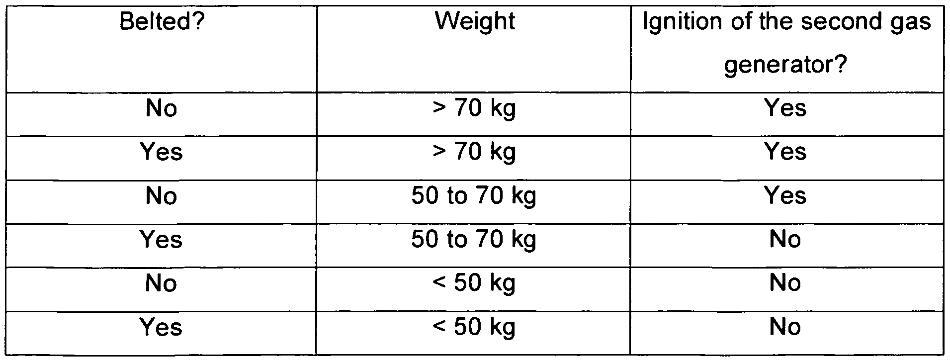
This decision-making matrix is to be understood only as an example, the values depend on the concrete circumstances of the vehicle. In addition, the decision- making matrix can always be designed to be much more differentiated and in par-
ticular it is also possible that there is no fixed time offset, but that an ideal time offset is calculated from the given parameters, which can also contain the severity of the accident. In cases in which the occupant is wearing a seatbelt and the second gas generator 16 is not ignited, the restraint function of the seatbelt with which the occupant is restrained is only slightly supported and it is prevented that the occupant's knee-shin area hits the dashboard 40. Very large forces are not transmitted into the occupant's thigh area in this case. In cases in which the second gas generator 16 is ignited, the knee airbag takes over a significant part of the restraining work, so that correspondingly large forces pass into the thighs of the occupant who is to be protected.
As already mentioned, the force peaks are already avoided solely on the basis of the time-offset ignition of the two gas generators and because of their different characteristics, so that in some application cases it can be possible to do without weight sensor 52 and without the belt sensor in belt buckle 54, wherein the second gas generator 16 is then always ignited. Mixed forms between the preferred embodiment described above and what has just been said are also possible, for example in such a way that the second gas generator 16 is always ignited in case of an unbelted occupant or always if a defined weight of the occupant is ex- ceeded.
Reference list
10 Housing
12 Knee airbag
12a impact surface
12b support surface
14 First gas generator (cold gas generator)
16 Second gas generator (pyrotechnic gas generator)
20 Controlling unit
21 First input
22 Second input
23 Third input
26 First output
27 Second output
40 Dashboard
50 Vehicle seat
52 Weight sensor
54 Belt buckle
56 Crash sensor
d depth
Claims
1. Knee airbag module comprising an inflating unit and a knee airbag (12) being inflatable between a lower area of the dash board (40) and a knee- shin-area of a car occupant by the inflating unit, said knee airbag having an impact wall and a support wall, the distance between the impact wall and the support wall defining the depth of the knee airbag, wherein the inflating unit has two stages with the second stage being ignitable with a time offset in respect to the first stage,
characterized in that the gas exhausted by the first stage is colder than the gas exhausted by the second stage and in that the knee airbag (12) reaches its maximum depth (d) and volume, if only the first stage of the inflating unit is ignited.
2. Knee airbag module according to claim 1 , characterized in that the inflating unit is a two stage gas generator.
3. Knee airbag module according to claim 1 , characterized in that the inflating unit is comprised of two gas generators, such that the first stage is formed by a first gas generator (14), namely a cold gas generator or a hybrid infla- tor, and the second stage is formed by a second gas generator (16), namely a pyrotechnic gas generator.
4. Knee airbag module according to one of the preceding claims, character- ized in that the time offset amounts up to 15 ms.
5. Knee airbag module according to claim 4, characterized in that the time offset is between 5 and 15 ms.
6. Knee airbag module according to one of the preceding claims, characterized in that a controlling unit (20) for controlling the inflating unit is provided, wherein the controlling unit (20) ignites the second stage only, if addition- ally to the detection of a frontal or a laterally offset frontal crash at least one additional condition is given.
Knee airbag unit according to claim 6, characterized in that the additional condition is the detection of an unbelted occupant.
Knee airbag according to claim 6 or claim 7, characterized in that the additional condition is the detection of an occupant whose size and/or weight exceeds a predetermined value.
Applications Claiming Priority (2)
| Application Number | Priority Date | Filing Date | Title |
|---|---|---|---|
| DE201110014650 DE102011014650A1 (en) | 2011-03-22 | 2011-03-22 | Knee airbag with a two-stage inflation unit |
| DE102011014650.4 | 2011-03-22 |
Publications (1)
| Publication Number | Publication Date |
|---|---|
| WO2012126608A1 true WO2012126608A1 (en) | 2012-09-27 |
Family
ID=45953061
Family Applications (1)
| Application Number | Title | Priority Date | Filing Date |
|---|---|---|---|
| PCT/EP2012/001218 Ceased WO2012126608A1 (en) | 2011-03-22 | 2012-03-20 | Knee airbag module with a two-stage inflating unit |
Country Status (2)
| Country | Link |
|---|---|
| DE (1) | DE102011014650A1 (en) |
| WO (1) | WO2012126608A1 (en) |
Cited By (1)
| Publication number | Priority date | Publication date | Assignee | Title |
|---|---|---|---|---|
| US9669788B2 (en) * | 2014-10-03 | 2017-06-06 | GM Global Technology Operations LLC | Knee airbag for motor vehicle |
Families Citing this family (1)
| Publication number | Priority date | Publication date | Assignee | Title |
|---|---|---|---|---|
| EP3594072B1 (en) | 2018-07-13 | 2020-12-09 | Volvo Car Corporation | Knee airbag arrangement |
Citations (5)
| Publication number | Priority date | Publication date | Assignee | Title |
|---|---|---|---|---|
| DE19842672A1 (en) | 1998-09-18 | 2000-03-23 | Volkswagen Ag | Glove compartment with integrated airbag for motor vehicles has tubular housings for gas generators, with each housing fixed to structure of vehicle and forming hinge point for cover flap |
| DE19846641A1 (en) * | 1998-10-09 | 2000-04-13 | Volkswagen Ag | Inflation system for vehicle occupant protection airbag has cold gas source and pyrotechnic gas generator able to be activated by crash sensor individually or sequentially at defined interval |
| DE202005006330U1 (en) * | 2005-04-20 | 2005-08-18 | Trw Automotive Safety Systems Gmbh | Airbag module |
| EP2106942A1 (en) * | 2008-04-03 | 2009-10-07 | IAC Group GmbH | Airbag assembly for a motor vehicle |
| US20120086190A1 (en) * | 2010-10-06 | 2012-04-12 | Slaats Paul M | Method and system for multi-stage inflation of a curtain airbag for ejection mitigation |
Family Cites Families (3)
| Publication number | Priority date | Publication date | Assignee | Title |
|---|---|---|---|---|
| DE19611718A1 (en) * | 1996-03-25 | 1997-10-02 | Trw Repa Gmbh | Method for controlling activation of a vehicle occupant restraint system, control system and vehicle occupant restraint system |
| DE29916526U1 (en) * | 1999-09-20 | 2000-02-17 | Trw Repa Gmbh | Vehicle occupant restraint |
| DE10154694A1 (en) * | 2001-11-09 | 2003-05-28 | Heinz Eyrainer | Protecting vehicle occupants involves unfolding first airbag towards front screen at start of activation, unfolding second airbag towards front screen between front screen and unfolded airbag |
-
2011
- 2011-03-22 DE DE201110014650 patent/DE102011014650A1/en not_active Withdrawn
-
2012
- 2012-03-20 WO PCT/EP2012/001218 patent/WO2012126608A1/en not_active Ceased
Patent Citations (5)
| Publication number | Priority date | Publication date | Assignee | Title |
|---|---|---|---|---|
| DE19842672A1 (en) | 1998-09-18 | 2000-03-23 | Volkswagen Ag | Glove compartment with integrated airbag for motor vehicles has tubular housings for gas generators, with each housing fixed to structure of vehicle and forming hinge point for cover flap |
| DE19846641A1 (en) * | 1998-10-09 | 2000-04-13 | Volkswagen Ag | Inflation system for vehicle occupant protection airbag has cold gas source and pyrotechnic gas generator able to be activated by crash sensor individually or sequentially at defined interval |
| DE202005006330U1 (en) * | 2005-04-20 | 2005-08-18 | Trw Automotive Safety Systems Gmbh | Airbag module |
| EP2106942A1 (en) * | 2008-04-03 | 2009-10-07 | IAC Group GmbH | Airbag assembly for a motor vehicle |
| US20120086190A1 (en) * | 2010-10-06 | 2012-04-12 | Slaats Paul M | Method and system for multi-stage inflation of a curtain airbag for ejection mitigation |
Cited By (1)
| Publication number | Priority date | Publication date | Assignee | Title |
|---|---|---|---|---|
| US9669788B2 (en) * | 2014-10-03 | 2017-06-06 | GM Global Technology Operations LLC | Knee airbag for motor vehicle |
Also Published As
| Publication number | Publication date |
|---|---|
| DE102011014650A1 (en) | 2012-09-27 |
Similar Documents
| Publication | Publication Date | Title |
|---|---|---|
| US7210701B2 (en) | Airbag system | |
| JP7260350B2 (en) | passenger protection device | |
| US20150074969A1 (en) | Integrated passenger airbag | |
| WO2008027100A1 (en) | Passenger-side airbag module | |
| JP6921684B2 (en) | Crew protection device | |
| JP3444344B2 (en) | Vehicle airbag device | |
| CN111688621B (en) | Method, device and system for protecting automobile collision passenger | |
| WO2005097559A3 (en) | Preemptive restorable vehicle occupant safety system | |
| JP2020152208A (en) | Crew protection device | |
| JP2002234414A (en) | Vehicle airbag device | |
| US20090179404A1 (en) | Optimised airbag module | |
| WO2012126608A1 (en) | Knee airbag module with a two-stage inflating unit | |
| JP2013166535A (en) | Occupant protection device | |
| EP2206632A1 (en) | Driver's air bag | |
| JP7129299B2 (en) | passenger protection device | |
| EP2394869B1 (en) | A motor vehicle safety arrangement for vehicle occupants | |
| Gstrein et al. | Improvement of airbag performance through pre-triggering | |
| JPH0930361A (en) | Occupant protection device for vehicles | |
| Shaout et al. | Automotive airbag technology: past, present and future | |
| KR0167624B1 (en) | Car occupant escape | |
| Lundell et al. | SIPSBAG-The Seat-Mounted Side Impact Airbag System | |
| EP2085269A1 (en) | Electronically controlled safety restraint system | |
| KR20070060569A (en) | Passenger seat airbag deployment control method | |
| US20030085558A1 (en) | Micro airbag safety system | |
| JP3484950B2 (en) | Vehicle airbag device |
Legal Events
| Date | Code | Title | Description |
|---|---|---|---|
| 121 | Ep: the epo has been informed by wipo that ep was designated in this application |
Ref document number: 12713877 Country of ref document: EP Kind code of ref document: A1 |
|
| NENP | Non-entry into the national phase |
Ref country code: DE |
|
| 122 | Ep: pct application non-entry in european phase |
Ref document number: 12713877 Country of ref document: EP Kind code of ref document: A1 |