WO2012124874A1 - 가스 절연 개폐 장치 - Google Patents
가스 절연 개폐 장치 Download PDFInfo
- Publication number
- WO2012124874A1 WO2012124874A1 PCT/KR2011/007886 KR2011007886W WO2012124874A1 WO 2012124874 A1 WO2012124874 A1 WO 2012124874A1 KR 2011007886 W KR2011007886 W KR 2011007886W WO 2012124874 A1 WO2012124874 A1 WO 2012124874A1
- Authority
- WO
- WIPO (PCT)
- Prior art keywords
- contact
- rotary
- sleeve
- movable contact
- rotary sleeve
- Prior art date
- Legal status (The legal status is an assumption and is not a legal conclusion. Google has not performed a legal analysis and makes no representation as to the accuracy of the status listed.)
- Ceased
Links
Images


Classifications
-
- H—ELECTRICITY
- H01—ELECTRIC ELEMENTS
- H01H—ELECTRIC SWITCHES; RELAYS; SELECTORS; EMERGENCY PROTECTIVE DEVICES
- H01H33/00—High-tension or heavy-current switches with arc-extinguishing or arc-preventing means
- H01H33/02—Details
-
- H—ELECTRICITY
- H01—ELECTRIC ELEMENTS
- H01H—ELECTRIC SWITCHES; RELAYS; SELECTORS; EMERGENCY PROTECTIVE DEVICES
- H01H33/00—High-tension or heavy-current switches with arc-extinguishing or arc-preventing means
- H01H33/02—Details
- H01H33/28—Power arrangements internal to the switch for operating the driving mechanism
-
- H—ELECTRICITY
- H01—ELECTRIC ELEMENTS
- H01H—ELECTRIC SWITCHES; RELAYS; SELECTORS; EMERGENCY PROTECTIVE DEVICES
- H01H31/00—Air-break switches for high tension without arc-extinguishing or arc-preventing means
- H01H31/26—Air-break switches for high tension without arc-extinguishing or arc-preventing means with movable contact that remains electrically connected to one line in open position of switch
- H01H31/28—Air-break switches for high tension without arc-extinguishing or arc-preventing means with movable contact that remains electrically connected to one line in open position of switch with angularly-movable contact
-
- H—ELECTRICITY
- H01—ELECTRIC ELEMENTS
- H01H—ELECTRIC SWITCHES; RELAYS; SELECTORS; EMERGENCY PROTECTIVE DEVICES
- H01H33/00—High-tension or heavy-current switches with arc-extinguishing or arc-preventing means
- H01H33/02—Details
- H01H33/42—Driving mechanisms
-
- H—ELECTRICITY
- H01—ELECTRIC ELEMENTS
- H01H—ELECTRIC SWITCHES; RELAYS; SELECTORS; EMERGENCY PROTECTIVE DEVICES
- H01H9/00—Details of switching devices, not covered by groups H01H1/00 - H01H7/00
- H01H9/02—Bases, casings, or covers
- H01H2009/0292—Transparent window or opening, e.g. for allowing visual inspection of contact position or contact condition
Definitions
- the disclosed technology relates to a gas insulated switchgear and a gas insulated switchgear which can generate a more accurate and stable disconnection signal and ground signal by preventing slip phenomenon and abnormal contact at the contact point of the switch.
- GIS Gas Insulated Switchgear
- SF 6 gas which has excellent insulation performance and extinguishing ability, as an insulating medium.
- the gas insulated switchgear is a unit that separates the existing disconnector, the circuit breaker, and the ground switch into an integrated unit so that the management of the device can be efficiently performed, and the volume of the device and the paper can be minimized.
- the demand for gas insulated switchgear increases, the development of related technologies has been very active.
- the overall configuration is further simplified and downsized, in which case the operation structure of the switch is complicated and a lot of power is applied to the operation of the switch. Because it is configured in a way that is required, there is a problem that it is not only inefficient but also difficult to maintain. In particular, such a switch has a problem such that an abnormal contact state may occur at the contact point of the contact point due to the operation structure, which may lead to a serious accident.
- a gas insulated switchgear is provided with a breaker, disconnector and a ground switch inside a pressure vessel filled with insulation gas, the breaker being supported by a separate connecting conductor inside the pressure vessel.
- the gas insulated switchgear is a rotary sleeve which wraps around the outer circumferential surface of the connecting conductor to be electrically contacted with the outer circumferential surface of the connecting conductor and is rotatable, a movable contact mounted to the rotating sleeve to integrally rotate with the rotating sleeve, And a drive unit for rotationally driving the rotary sleeve and the first and second fixed contacts disposed on the rotary path of the movable contact so as to selectively contact the movable contact.
- the disconnector or grounding switch is selectively operated as the movable contact selectively contacts the first fixed contact or the second fixed contact.
- the drive unit is disposed outside the pressure vessel is operated by a user lever;
- a coupling node mounted at one side of the rotating sleeve;
- a link module interconnecting the manipulation lever and the coupling node so that the rotary sleeve rotates in association with the manipulation of the manipulation lever.
- the link module may further include a rotary shaft rotating about a rotation axis in a longitudinal direction by an operation of the operation lever, a rotary link having one end coupled to the rotary shaft and rotating integrally with the rotary shaft, and both ends of the rotary link and It may be configured to include a connecting link rotatably linked to each coupling node.
- the movable contact may include a support disposed to protrude along the radial direction of the rotating sleeve; And it may be configured to include a contact portion protruding to both sides in the circumferential direction of the rotary sleeve at the end of the support.
- contact grooves may be formed in the first fixed contact and the second fixed contact so that the contact portion of the movable contact may be inserted.
- the pressure vessel may be equipped with a check window to observe the operating state of the movable contact.
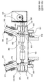
- FIG. 1 is a view illustrating a configuration of a gas insulated switchgear according to an embodiment of the disclosed technology.
- FIG. 2 is a perspective view for explaining a switching operation related configuration in the gas insulated switchgear of FIG. 1.
- FIG. 3 is a cross-sectional view schematically showing the switching operation state shown in FIG.
- FIG. 4 is a cross-sectional view illustrating a reference operation state of the gas insulated switchgear shown in FIG. 3.
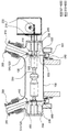
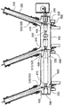
- FIG 5 and 6 are views illustrating a configuration of a gas insulated switchgear according to another embodiment of the disclosed technology.
- first and second are intended to distinguish one component from another component, and the scope of rights should not be limited by these terms.
- first component may be named a second component, and similarly, the second component may also be named a first component.
- FIG. 1 is a view illustrating a configuration of a gas insulated switchgear according to an embodiment of the disclosed technology
- FIG. 2 is a perspective view illustrating a configuration related to switching operation in the gas insulated switchgear of FIG. 1, and FIG. It is sectional drawing which shows the switching operation state shown in FIG. 2 schematically
- FIG. 4 is sectional drawing explaining the reference operation state of the gas insulation switching device shown in FIG.
- the gas insulated switchgear is configured such that the disconnector and the folding switch disposed inside the pressure vessel are selectively operated through a switching operation by one switch, and the rotary sleeve 400 and the movable contact 410 are configured for the switching operation. And the first and second fixed contacts 510 and 520 and the driving unit 600.
- the breaker 200, the disconnector and the ground switch are arranged in the sealed metal pressure vessel 100 filled with an insulating gas such as SF 6 .
- the disconnecting device and the grounding switch may be selectively operated through a switching operation by one switch, and may not be configured as a separate independent device, but may be configured in a form in which a function is simply performed by the switching operation. That is, it may be configured in a disconnected state or a grounded state depending on the contact state of the switch contact.
- the pressure vessel 100 is mounted with a bushing 300 or a cable head (not shown) so that the external connection conductor can be connected, and the bushing conductor 310 inside the bushing 300 for electrical connection with the external connection conductor. ) Are combined.
- the bushing conductor 310 is preferably formed in a wedge shape in which the diameter decreases toward the pressure vessel 100 as shown in FIG. 1 (see FIG. 6), thereby allowing the bushing without additional insulation support. Support for 300 is possible, and the electric field can be stabilized centrally.
- at least two bushings 300 may be installed.
- the breaker 200 is located in the center of the pressure vessel 100, the hollow pipe-shaped insulation support 240 mounted on both ends of the pressure vessel 100, and the hollow hollow coupled to the insulating support 240 It is supported by a connecting conductor 230 in the form of a pipe.
- the breaker 200 is operated by a separate operating arm 210 and the drive lever 220 for linear reciprocating movement of the operating arm 210 is configured to block the flow of current.
- Rotating sleeve 400 is formed in the form of a hollow pipe is coupled to the connecting conductor 230 to move around the outer circumferential surface of the connecting conductor 230. At this time, the rotary sleeve 400 is coupled to keep the electrical contact with the connecting conductor 230 at all times even in the state of rotational movement, for this purpose, a separate conductive lubricant of the rotating sleeve 400 and the connecting conductor 230
- the contact surface may be filled, but may be simply configured in such a manner that the inner surface of the rotary sleeve 400 and the outer surface of the connecting conductor 230 directly contact each other.
- the movable contact 410 is mounted to the rotating sleeve 400 so as to rotate integrally with the rotating sleeve 400, and the first and second fixed contacts 510 and 520 have the movable contact 410 integrated with the rotating sleeve 400.
- the first and second fixed contacts 510 and 520 have the movable contact 410 integrated with the rotating sleeve 400.
- In order to selectively contact with the movable contact 410 in accordance with the rotational movement of the rotary contact is arranged on the rotational movement path of the movable contact 410 spaced apart from each other.
- the first fixed contact 510 is a contact for performing the disconnect function for the external connection conductor
- the disconnect function is performed.
- the function of the disconnector is performed.
- the second fixed contact 520 is a contact for performing a grounding function for the external connection conductor. In other words, the function of the folding switch is operated.
- the drive unit 600 is configured to drive the rotary sleeve 400 in a rotational manner, preferably configured in such a manner as to operate by a user's operation, but configured to be electrically operated using a separate drive motor, if necessary. It could be.
- the gas insulated switchgear is rotated by the drive unit 600, the rotation sleeve 400, accordingly, the movable contact 410 is rotated integrally and the first and second fixed contacts (510, 520) Selective contact with and disconnection function or grounding function is performed.
- the rotational movement configuration by the drive unit 600 is not a connection conductor 230 for supporting the circuit breaker 200, unlike the prior art, and is a rotary sleeve 400 in electrical contact with the connection conductor 230, Since the operation force for the rotation sleeve 400 is relatively small, the operation is simple, and thus, the configuration of the driving unit 600 can be simplified, and even when damage is caused to the contact, the rotation is performed irrespective of the connecting conductor 230. Maintenance can also be easily performed since only the sleeve 400 can be exchanged and repaired separately.
- the drive unit 600 is disposed outside the pressure vessel 100, the operation lever 610 to be operated by the user, the coupling node 620 mounted to one side of the rotary sleeve 400, It may be configured to include a link module 630 for interconnecting the operation lever 610 and the coupling node 620 so that the rotary sleeve 400 rotates in conjunction with the operation of the operation lever 610. That is, when the user operates the operation lever 610 mounted to the outside of the pressure vessel 100, the link module 630 is configured to rotate the rotary sleeve 400 in conjunction with the operation lever 610, thereby rotating It may be configured to enable a simple rotation operation for the sleeve 400.
- the link module 630 is rotated about the axis of rotation in the longitudinal direction by the operation of the operation lever 610, and one end is coupled to the rotation shaft 631 to center the rotation shaft 631.
- Rotation link 632 that rotates integrally with the rotary shaft 631, and both ends of the coupling link 633 is rotatably linked to the rotary link 632 and coupling node 620, respectively. have.
- the rotary link 632 with the rotary shaft 631 rotates, the connecting link 633 connected to the rotary link 632 is moved and the rotation sleeve 400 of the By rotating the coupling node 620, the rotating sleeve 400 is rotated.
- the movable contact 410 rotates at the same time and selectively contacts the first fixed contact 510 or the second fixed contact 520.
- Such a drive unit 600 is an example, alternatively, it may be changed in various ways using a variety of power transmission elements such as a chain or belt.
- the movable contact 410 is mounted to protrude to the outer circumferential surface of the rotary sleeve 400, as shown in Figures 2 and 3, the support portion 411 is disposed to protrude along the radial direction of the rotary sleeve 400, and the support portion It may be configured to include a contact portion 412 protruding to both sides in the circumferential direction of the rotary sleeve 400 at the end of the 411.
- contact grooves 511 and 521 may be formed in the first and second fixed contacts 510 and 520 so that the contact parts 412 of the movable contact 410 may be inserted, respectively.
- the movable contact 410 may be a general contact structure. In the process of contacting the first fixed contact 510 or the second fixed contact 520, a slip phenomenon may occur due to the rotational movement speed, or the contact may not be possible due to the inertia force.
- the movable contact 410 and the first and second fixed contacts 510 and 520 may be coupled to each other in a fitting manner while the movable contact 410 contacts the first and second fixed contacts 510 and 520.
- the contact portion 412 and the contact grooves 511 and 521 are formed, and through this, the contact portion 412 and the contact grooves 511 and 521 may be coupled to each other at an accurate position without a slip phenomenon.
- the gas insulated switchgear can generate a more accurate and stable short-circuit signal and a ground signal by performing an accurate contact operation on the contact point.
- a separate inspection window 110 is mounted on the pressure vessel 100 so that the operation state of the movable contact 410 can be visually observed from the outside, and the inspection window 110 includes a movable contact ( It will be desirable to be manufactured to a size that can observe the entire rotational movement section of the 410.
- the movable contact 410 contacts the first fixed contact 510 or the second fixed contact 520 as shown in FIGS. 3A and 3B and may generate a short signal and a ground signal.
- the movable contact 410 is maintained in an intermediate rotation state such that the movable contact 410 does not contact either of the first and second fixed contacts 510 and 520.
- no short-circuit or grounding function is carried out and the function is to ensure that electricity flows normally to the externally connected conductors. That is, when the gas insulated switchgear is operated in general, and the short circuit or the ground function is to be performed as necessary, the operation lever 610 is operated to change the position of the movable contact 410. It will perform the function.
- the rotating sleeve 400 to which the movable contact 410 is mounted is restrained from free rotation in the rotational position state of the reference state.
- a separate restraining means may be provided as shown in FIG. 4. have.
- the restraining means is engaged with the engaging groove 231 formed on the outer circumferential surface of the connecting conductor 230 and the inner circumferential surface of the rotating sleeve 400 and the engaging projection 402 which can be engaged with the engaging groove 231 of the connecting conductor 230. It may be configured to include).
- a seating groove 401 is formed on the inner circumferential surface of the rotary sleeve 400, and the locking protrusion 402 is configured to elastically protrude out of the seating groove 401 by a separate elastic member 403. Can be.
- the locking projection 402 is protruded from the seating groove 401 to be engaged with the locking groove 231 of the connecting conductor 230 only when the rotating sleeve 400 is positioned in the reference state, and the rotating sleeve 400 In the case of rotating rotation is pressed again into the seating groove 401. Therefore, when the rotation sleeve 400 is located in the reference state, free rotation of the rotation sleeve 400 is constrained by the engagement of the locking protrusion 402 and the locking groove 231, and the rotation sleeve 400 rotates.
- the restraining means is exemplary, and alternatively, the driving unit 600 including the operation lever 610 may be variously modified, such as a restraining means for preventing free rotation in various forms.
- FIG 5 and 6 are views illustrating a configuration of a gas insulated switchgear according to another embodiment of the disclosed technology.
- the gas insulation switchgear includes a movable contact 410 such that the first and second fixed contacts 510 and 520 connected to the bushing conductor 310 and the movable contact 410 can be contacted in a more stable structure.
- the bushing conductor 310 may be inclinedly mounted on the rotating sleeve 400 to be disposed on the same straight line as the inclined arrangement direction of the bushing conductor 310.
- three bushings 300 may be mounted in the pressure vessel 100, and in this case, three first and three bushings 300 may be connected to each of the bushing conductors 310 of each bushing 300.
- Second fixed contacts 510 and 520 are formed, and likewise, three movable contacts 410 may be formed.
- the number of such bushings 300 may be mounted more, and thus, the first and second fixed contacts 510 and 520 and the movable contacts 410 may also be formed in plural numbers corresponding to the number of bushings 300. have.
- each movable contact 410 may be configured to operate simultaneously through the same one drive unit 600, for example, each of the rotating shaft 631 is connected to one form It would be possible to configure it as
- the disclosed technique can have the following effects. However, since a specific embodiment does not mean to include all of the following effects or only the following effects, it should not be understood that the scope of the disclosed technology is limited by this.
- the disconnector and the grounding switch disposed inside the pressure vessel are selectively operated through a single switch, and a separate rotating sleeve for the switch operation is simplified to simplify the structure of the switch and the driving force required for the switch operation. By reducing this, it is possible to operate more simply and easily, and there is an effect of easy maintenance.
- the movable contact and the fixed contact are contacted with each other by inserting coupling method, thereby preventing slipping and abnormal contact at the contact portion of the contact, thereby providing a more accurate and stable disconnect signal.
- the ground signal can be generated, thereby preventing an accident due to an operation error in advance.
- first fixed contact 520 second fixed contact
Landscapes
- Gas-Insulated Switchgears (AREA)
Abstract
가스 절연 개폐 장치는 절연 가스가 충진된 압력 용기 내부에 차단기, 단로기 및 접지 개폐기가 배치되고, 상기 차단기가 상기 압력 용기 내부에서 별도의 연결 도체에 의해 지지된다. 가스 절연 개폐 장치는 상기 연결 도체의 외주면에 전기적으로 접촉하며 회전 이동 가능하도록 상기 연결 도체의 외주면을 감싸며 결합되는 회전 슬리브, 상기 회전 슬리브와 일체로 회전 이동하도록 상기 회전 슬리브에 장착되는 가동 접점, 상기 가동 접점과 선택적으로 접촉하도록 상기 가동 접점의 회전 경로 상에 상호 이격되게 배치되는 제 1 및 제 2 고정 접점 및 상기 회전 슬리브를 회전 구동하는 구동 유닛을 포함한다. 상기 가동 접점이 상기 제 1 고정 접점 또는 제 2 고정 접점에 선택적으로 접촉함에 따라 상기 단로기 또는 접지 개폐기가 선택적으로 작동한다.
Description
개시된 기술은 가스 절연 개폐 장치에 관한 것으로, 스위치의 접점 접촉 부위에서 슬립 현상 및 비정상적인 접촉을 방지하여 더욱 정확하고 안정적인 단로 신호와 접지 신호를 생성할 수 있는 가스 절연 개폐 장치에 관한 것이다.
최근 산업의 발달로 인한 전력 수요의 급증에 따라 전력 계통도 대용량, 초고압화 되어가고 있으며, 이에 따른 전력 설비의 안정화 및 신뢰도는 매우 중요한 사항으로 대두되고 있다. 전력 수요의 급증에 따른 초고압 변전 설비는 용지 확보의 곤란, 유지 보수 비용의 과다, 안전성 확보 등의 이유로 주회로 계통은 밀폐, 은폐화되고 제어 계통은 전자화되는 추세로 급속도로 변화되고 있으며, 이러한 추세에 따라 기존의 공기 또는 유류 절연형 변전설비는 가스 절연형 변전 설비로 교체되어 가고 있다.
가스 절연 개폐 장치(GIS: Gas Insulated Switchgear)는 차단기, 단로기, 접기 개폐기 등의 개폐 설비와, 변성기, 피뢰기, 주회로 모선 등을 금속제 압력 용기 내에 일괄 수납하고, 충전부는 고체 절연물(spacer)로 지지하고 있으며 탱크 내부에는 절연 성능과 소호 능력이 우수한 SF6 가스를 절연 매체로 하여 충진 밀봉한 변전 설비 시스템을 말한다.
이러한 가스 절연 개폐 장치는 기존에 분리 구성되어 있던 단로기, 차단기, 접지 개폐기 등을 일체형으로 유니트화 함으로써, 장치의 관리를 효율적으로 할 수 있음은 물론 장치의 점유 용적 및 용지를 최소화할 수 있는 특징을 가지며, 최근 가스 절연 개폐 장치의 수요 급증에 따라 관련 분야의 기술 개발이 매우 활발하게 진행되고 있다.
예를 들면, 압력 용기 내부에 배치된 단로기와 접지 개폐기를 하나의 스위치를 통해 선택적으로 작동하도록 함으로써, 전체 구성을 더욱 단순화 소형화하고 있는데, 이 경우 스위치의 작동 구조가 복잡하고 스위치 작동에 많은 동력을 필요로 하는 방식으로 구성되기 때문에 비효율적일 뿐만 아니라 유지 보수가 어렵다는 등의 문제가 있었다. 특히, 이러한 하나의 스위치는 작동 구조상 접점의 접촉 부위에서 비정상적인 접촉 상태가 발생하여 심각한 사고로 이어질 수 있는 등의 문제가 있었다.
실시예들 중에서, 가스 절연 개폐 장치는 절연 가스가 충진된 압력 용기 내부에 차단기, 단로기 및 접지 개폐기가 배치되고, 상기 차단기가 상기 압력 용기 내부에서 별도의 연결 도체에 의해 지지된다. 가스 절연 개폐 장치는 상기 연결 도체의 외주면에 전기적으로 접촉하며 회전 이동 가능하도록 상기 연결 도체의 외주면을 감싸며 결합되는 회전 슬리브, 상기 회전 슬리브와 일체로 회전 이동하도록 상기 회전 슬리브에 장착되는 가동 접점, 상기 가동 접점과 선택적으로 접촉하도록 상기 가동 접점의 회전 경로 상에 상호 이격되게 배치되는 제 1 및 제 2 고정 접점 및 상기 회전 슬리브를 회전 구동하는 구동 유닛을 포함한다. 상기 가동 접점이 상기 제 1 고정 접점 또는 제 2 고정 접점에 선택적으로 접촉함에 따라 상기 단로기 또는 접지 개폐기가 선택적으로 작동한다.
이때, 상기 구동 유닛은 상기 압력 용기의 외부에 배치되어 사용자에 의해 조작되는 조작 레버; 상기 회전 슬리브의 일측에 장착되는 결합 노드; 및 상기 조작 레버의 조작에 연동하여 상기 회전 슬리브가 회전 이동하도록 상기 조작 레버와 상기 결합 노드를 상호 연결하는 링크 모듈을 포함하여 구성될 수 있다.
또한, 상기 링크 모듈은 상기 조작 레버의 조작에 의해 길이 방향의 회전축을 중심으로 회전하는 회전 샤프트, 일단부가 상기 회전 샤프트에 결합되어 상기 회전 샤프트와 일체로 회전하는 회전 링크 및 양단부가 상기 회전 링크 및 결합 노드에 각각 회전 가능하게 링크 결합되는 연결 링크를 포함하여 구성될 수 있다.
일 실시예에서, 상기 가동 접점은 상기 회전 슬리브의 반경 방향을 따라 돌출되게 배치되는 지지부; 및 상기 지지부의 끝단에 상기 회전 슬리브의 원주 방향을 따라 양측으로 돌출되는 접점부를 포함하여 구성될 수 있다. 일 실시예에서, 상기 제 1 고정 접점 및 제 2 고정 접점에는 상기 가동 접점의 접점부가 삽입될 수 있도록 접점홈이 각각 형성될 수 있다. 일 실시예에서, 상기 압력 용기에는 상기 가동 접점의 동작 상태를 관찰할 수 있도록 점검창이 장착될 수 있다.
도 1은 개시된 기술의 일 실시예에 따른 가스 절연 개폐 장치의 구성을 설명하는 도면이다.
도 2는 도 1의 가스 절연 개폐 장치에 있는 스위칭 동작 관련 구성을 설명하는 사시도이다.
도 3은 도 2에 나타난 스위칭 동작 상태를 개략적으로 도시한 단면도이다.
도 4는 도 3에 나타난 가스 절연 개폐 장치의 기준 동작 상태를 설명하는 단면도이다.
도 5 및 도 6들은 개시된 기술의 다른 일 실시예에 따른 가스 절연 개폐 장치의 구성을 설명하는 도면이다.
본 출원에 관한 설명은 구조적 내지 기능적 설명을 위한 실시예에 불과하므로, 개시된 기술의 권리범위는 본문에 설명된 실시예에 의하여 제한되는 것으로 해석되어서는 아니 된다. 즉, 실시예는 다양한 변경이 가능하고 여러 가지 형태를 가질 수 있으므로 개시된 기술의 권리범위는 기술적 사상을 실현할 수 있는 균등물들을 포함하는 것으로 이해되어야 한다.
한편, 본 출원에서 서술되는 용어의 의미는 다음과 같이 이해되어야 할 것이다.
"제1", "제2" 등의 용어는 하나의 구성요소를 다른 구성요소로부터 구별하기 위한 것으로, 이들 용어들에 의해 권리범위가 한정되어서는 아니 된다. 예를 들어, 제1 구성요소는 제2 구성요소로 명명될 수 있고, 유사하게 제2 구성요소도 제1 구성요소로 명명될 수 있다.
어떤 구성요소가 다른 구성요소에 "연결되어"있다고 언급된 때에는, 그 다른 구성요소에 직접적으로 연결될 수도 있지만, 중간에 다른 구성요소가 존재할 수도 있다고 이해되어야 할 것이다. 반면에, 어떤 구성요소가 다른 구성요소에 "직접 연결되어"있다고 언급된 때에는, 그 외 구성요소는 존재하지 않는 것으로 이해되어야 할 것이다. 한편, 구성요소들 간의 관계를 설명하는 다른 표현들, 즉 "~사이에"와 "바로 ~사이에" 또는 "~에 이웃하는"과 "~에 직접 이웃하는" 등도 마찬가지로 해석되어야 한다.
단수의 표현은 문맥상 명백하게 다르게 뜻하지 않는 한 복수의 표현을 포함하는 것으로 이해되어야 하고, "포함하다"또는 "가지다" 등의 용어는 설시된 특징, 숫자, 단계, 동작, 구성요소, 부분품 또는 이들을 조합한 것이 존재함을 지정하려는 것이며, 하나 또는 그 이상의 다른 특징이나 숫자, 단계, 동작, 구성요소, 부분품 또는 이들을 조합한 것들의 존재 또는 부가 가능성을 미리 배제하지 않는 것으로 이해되어야 한다.
여기서 사용되는 모든 용어들은 다르게 정의되지 않는 한, 개시된 기술이 속하는 분야에서 통상의 지식을 가진 자에 의해 일반적으로 이해되는 것과 동일한 의미를 가진다. 일반적으로 사용되는 사전에 정의되어 있는 용어들은 관련 기술의 문맥상 가지는 의미와 일치하는 것으로 해석되어야 하며, 본 출원에서 명백하게 정의하지 않는 한 이상적이거나 과도하게 형식적인 의미를 지니는 것으로 해석될 수 없다.
도 1은 개시된 기술의 일 실시예에 따른 가스 절연 개폐 장치의 구성을 설명하는 도면이이고, 도 2는 도 1의 가스 절연 개폐 장치에 있는 스위칭 동작 관련 구성을 설명하는 사시도이며, 도 3은 도 2에 나타난 스위칭 동작 상태를 개략적으로 도시한 단면도이고, 도 4는 도 3에 나타난 가스 절연 개폐 장치의 기준 동작 상태를 설명하는 단면도이다.
가스 절연 개폐 장치는 압력 용기 내부에 배치된 단로기 및 접기 개폐기가 하나의 스위치에 의한 스위칭 동작을 통해 선택적으로 작동하도록 구성되며, 스위칭 동작을 위한 구성으로 회전 슬리브(400)와, 가동 접점(410)과, 제 1 및 제 2 고정 접점(510,520)과, 구동 유닛(600)을 포함하여 구성된다.
먼저, 가스 절연 개폐 장치의 전체적인 구성을 살펴보면, SF6와 같은 절연 가스가 충진된 밀폐된 금속제의 압력 용기(100) 내부에 차단기(200), 단로기 및 접지 개폐기 등이 배치된 형태로 구성된다. 이때, 단로기 및 접지 개폐기는 하나의 스위치에 의한 스위칭 동작을 통해 선택적으로 작동하는 것으로 별도의 독립적인 장치로 구성되지 않고, 단순히 스위칭 동작에 의해 기능이 수행되는 형태로 구성될 수 있다. 즉, 스위치 접점의 접촉 상태에 따라 단로 상태가 되거나 또는 접지 상태가 되는 방식으로 구성될 수 있다.
압력 용기(100)의 일측에는 외부 연결 도체가 연결될 수 있도록 부싱(300) 또는 케이블 헤드(미도시)가 장착되며, 부싱(300)의 내부에는 외부 연결 도체와의 전기적 연결을 위해 부싱 도체(310)가 결합된다. 이때, 부싱 도체(310)는 도 1에 도시된 바와 같이 압력 용기(100) 방향으로 갈수록 직경이 감소하는 쐐기 형태로 형성되는 것이 바람직하며(도 6 참조), 이를 통해 별도의 추가적인 절연 지지물 없이도 부싱(300)에 대한 지지가 가능하며, 전계를 집중 안정화시킬 수 있다. 한편, 이러한 부싱(300)은 적어도 2개 이상 다수개 설치될 수 있다.
*차단기(200)는 압력 용기(100) 내부 공간의 중심부에 위치하는데, 압력 용기(100)의 양단부에 장착된 중공 파이프 형태의 절연 서포트(240)와, 절연 서포트(240)에 연결 결합된 중공 파이프 형태의 연결 도체(230)에 의해 지지된다. 이러한 차단기(200)는 별도의 작동암(210) 및 작동암(210)을 축방향으로 직선 왕복 이동시키는 구동 레버(220)에 의해 작동하며 전류의 흐름을 차단하도록 구성된다.
회전 슬리브(400)는 중공 파이프 형태로 형성되어 연결 도체(230)의 외주면을 감싸며 회전 이동 하도록 연결 도체(230)에 결합된다. 이때, 회전 슬리브(400)는 회전 이동하는 상태에서도 항상 연결 도체(230)와 전기적으로 접촉한 상태를 유지하도록 결합되는데, 이를 위해 별도의 전도성 윤활유가 회전 슬리브(400)와 연결 도체(230)의 접촉면에 충전될 수 있으나, 단순히 회전 슬리브(400)의 내측면과 연결 도체(230)의 외측면이 직접 접촉하는 방식으로 구성될 수도 있다.
가동 접점(410)은 회전 슬리브(400)와 일체로 회전 이동하도록 회전 슬리브(400)에 장착되며, 제 1 및 제 2 고정 접점(510,520)은 가동 접점(410)이 회전 슬리브(400)와 일체로 회전 이동함에 따라 가동 접점(410)과 선택적으로 접촉하도록 가동 접점(410)의 회전 이동 경로 상에 상호 이격되게 배치된다.
이때, 제 1 고정 접점(510)은 외부 연결 도체에 대한 단로 기능을 수행하기 위한 접점으로 가동 접점(410)이 제 1 고정 접점(510)에 접촉하면, 단로 기능이 수행된다. 다시 말해, 단로기가 작동한 상태의 기능이 수행된다. 한편, 제 2 고정 접점(520)은 외부 연결 도체에 대한 접지 기능을 수행하기 위한 접점으로 가동 접점(410)이 제 2 고정 접점(520)에 접촉하면, 접지 기능이 수행된다. 다시 말해, 접기 개폐기가 작동한 상태의 기능이 수행된다.
구동 유닛(600)은 회전 슬리브(400)를 회전 구동하는 구성으로, 사용자의 조작에 의해 작동하는 방식으로 구성하는 것이 바람직하나, 필요에 따라서는 별도의 구동 모터 등을 사용하여 전기적으로 작동하도록 구성될 수도 있을 것이다.
이러한 구조에 따라, 가스 절연 개폐 장치는 구동 유닛(600)에 의해 회전 슬리브(400)가 회전 이동하면, 이에 따라 가동 접점(410)이 일체로 회전 이동하며 제 1 및 제 2 고정 접점(510,520)에 선택적으로 접촉하며 단로 기능 또는 접지 기능이 수행된다. 이때, 구동 유닛(600)에 의해 회전 이동하는 구성은 종래 기술과 달리 차단기(200)를 지지하는 연결 도체(230)가 아니며, 연결 도체(230)와 전기적으로 접촉하는 회전 슬리브(400)이므로, 회전 슬리브(400)에 대한 조작력이 상대적으로 작게 요구되어 조작이 간편하고, 이에 따라 구동 유닛(600)의 구성 또한 단순화할 수 있으며, 접점에 손상이 발생한 경우에도 연결 도체(230)와는 무관하게 회전 슬리브(400)만 별도로 교환 수리할 수 있으므로 유지 보수 또한 용이하게 수행할 수 있다.
다음으로, 가스 절연 개폐 장치의 스위칭 동작 관련 구성을 좀 더 자세히 살펴본다.
일 실시예에서, 구동 유닛(600)은 압력 용기(100)의 외부에 배치되어 사용자에 의해 조작되는 조작 레버(610)와, 회전 슬리브(400)의 일측에 장착되는 결합 노드(620)와, 조작 레버(610)의 조작에 연동하여 회전 슬리브(400)가 회전 이동하도록 조작 레버(610)와 결합 노드(620)를 상호 연결하는 링크 모듈(630)을 포함하여 구성될 수 있다. 즉, 사용자가 압력 용기(100)의 외부에 장착된 조작 레버(610)를 조작하면, 조작 레버(610)에 연동하여 링크 모듈(630)이 회전 슬리브(400)를 회전시키도록 구성함으로써, 회전 슬리브(400)에 대한 간편한 회전 조작이 가능하도록 구성될 수 있다.
이때, 링크 모듈(630)은 조작 레버(610)의 조작에 의해 길이 방향의 회전축을 중심으로 회전하는 회전 샤프트(631)와, 일단부가 회전 샤프트(631)에 결합되어 회전 샤프트(631)를 중심으로 회전 샤프트(631)와 일체로 회전하는 회전 링크(632)와, 양단부가 회전 링크(632) 및 결합 노드(620)에 각각 회전 가능하게 링크 결합되는 연결 링크(633)를 포함하여 구성될 수 있다.
따라서, 사용자가 조작 레버(610)를 조작하면, 회전 샤프트(631)와 함께 회전 링크(632)가 회전하고, 회전 링크(632)에 연결된 연결 링크(633)가 이동하며 회전 슬리브(400)의 결합 노드(620)를 회전 이동시킴으로써, 회전 슬리브(400)가 회전 이동하게 된다. 이러한 회전 슬리브(400)의 회전 이동에 따라 가동 접점(410)이 동시에 회전 이동하며 제 1 고정 접점(510) 또는 제 2 고정 접점(520)에 선택적으로 접촉하게 된다.
예를 들어, 도 3의 (a)에 도시된 바와 같이 조작 레버(610)의 조작에 의해 회전 샤프트(631)를 반시계 방향으로 회전시키면, 회전 링크(632)가 동시에 회전하고, 이에 따라 연결 링크(633)가 하향 이동하며 회전 슬리브(400)의 결합 노드(620)를 견인함으로써, 회전 슬리브(400)가 반시계 방향으로 회전한다. 회전 슬리브(400)가 반시계 방향으로 회전하면, 회전 슬리브(400)에 장착된 가동 접점(410)이 동시에 회전하며 회전 경로 상에 배치된 제 1 고정 접점(510)에 접촉한다. 반대로, 도 3의 (b)에 도시된 바와 같이 조작 레버(610)의 조작에 의해 회전 샤프트(631)가 시계 방향으로 회전하면, 도 3의 (a)와는 반대 방향의 운동 메카니즘이 작용하여 회전 슬리브(400)가 시계 방향으로 회전하고, 회전 슬리브(400)에 장착된 가동 접점(410)은 제 2 고정 접점(520)에 접촉하게 된다.
한편, 이와 같은 구동 유닛(600)의 구성은 예시적인 것으로, 이와 달리 체인 또는 벨트와 같은 다양한 동력 전달 요소 등을 이용하여 다양한 방식으로 변경될 수 있을 것이다.
가동 접점(410)은 회전 슬리브(400)의 외주면에 돌출되게 장착되는데, 도 2 및 도 3에 도시된 바와 같이 회전 슬리브(400)의 반경 방향을 따라 돌출되게 배치되는 지지부(411)와, 지지부(411)의 끝단에 회전 슬리브(400)의 원주 방향을 따라 양측으로 돌출 형성되는 접점부(412)를 포함하여 구성될 수 있다. 한편, 이에 대응하여 제 1 및 제 2 고정 접점(510,520)에는 각각 가동 접점(410)의 접점부(412)가 삽입될 수 있도록 접점홈(511,521)이 형성될 수 있다.
이러한 구조에 따라 가동 접점(410)이 제 1 및 제 2 고정 접점(510,520)에 접촉하는 과정에서 슬립 현상에 따른 부정확한 접촉 상태가 방지된다. 좀 더 자세히 살펴보면, 가동 접점(410)은 회전 슬리브(400)와 함께 회전 이동하며 제 1 고정 접점(510) 또는 제 2 고정 접점(520)에 접촉하므로, 일반적인 접촉 구조인 경우에는 가동 접점(410)이 제 1 고정 접점(510) 또는 제 2 고정 접점(520)에 접촉하는 과정에서 회전 이동 속도에 의해 슬립 현상이 발생하거나 또는 관성력에 의해 정확한 위치에 접촉하지 못하는 경우가 발생할 수 있다. 따라서, 가동 접점(410)과 제 1 및 제 2 고정 접점(510,520)은 가동 접점(410)이 제 1 및 제 2 고정 접점(510,520)에 접촉하는 과정에서 상호 끼워맞춤 방식으로 접촉 결합할 수 있도록 접점부(412)와 접점홈(511,521)이 형성되며, 이를 통해 슬립 현상 없이 정확한 위치에서 상호 접촉 결합할 수 있다.
따라서, 가스 절연 개폐 장치는 접점에 대한 정확한 접촉 동작이 이루어짐으로써, 더욱 정확하고 안정적인 단락 신호 및 접지 신호를 생성할 수 있다.
또한, 압력 용기(100)에는 이러한 가동 접점(410)의 동작 상태를 외부에서 육안으로 관찰할 수 있도록 별도의 점검창(110)이 장착되는 것이 바람직하며, 이러한 점검창(110)은 가동 접점(410)의 전체 회전 이동 구간을 모두 관찰할 수 있는 정도의 크기로 제작되는 것이 바람직할 것이다.
한편, 가동 접점(410)은 도 3의 (a) 및 (b)에 도시된 바와 같이 제 1 고정 접점(510) 또는 제 2 고정 접점(520)에 접촉하며 단락 신호 및 접지 신호를 생성할 수 있는데, 이러한 신호 생성 동작 이외의 기준 상태에서는 도 4에 도시된 바와 같이 가동 접점(410)이 제 1 및 제 2 고정 접점(510,520)의 어느 쪽에도 접촉하지 않도록 중간 회전 상태를 유지하게 된다. 이러한 기준 상태에서는 단락 또는 접지 기능이 수행되지 않고 외부 연결 도체에 정상적으로 전기가 흘러가도록 하는 기능이 수행된다. 즉, 일반적으로 기준 상태를 유지하며 가스 절연 개폐 장치가 작동하고, 필요에 따라 단락 또는 접지 기능을 수행하고자 하는 경우 조작 레버(610)를 조작하여 가동 접점(410)의 위치를 변경시키는 방식으로 해당 기능을 수행하게 된다.
따라서, 가동 접점(410)이 장착되는 회전 슬리브(400)는 기준 상태의 회전 위치 상태에서 자유 회전하지 못하도록 구속되는 것이 바람직한데, 이를 위해 도 4에 도시된 바와 같이 별도의 구속 수단이 구비될 수 있다. 이러한 구속 수단은 연결 도체(230)의 외주면에 형성된 걸림홈(231)과, 회전 슬리브(400)의 내주면에 결합되며 연결 도체(230)의 걸림홈(231)에 맞물림될 수 있는 걸림 돌기(402)를 포함하여 구성될 수 있다. 이때, 회전 슬리브(400)의 내주면에는 안착홈(401)이 형성되고, 걸림 돌기(402)가 별도의 탄성 부재(403)에 의해 안착홈(401)의 외부로 돌출되게 탄성 편의되는 형태로 구성될 수 있다.
이러한 구성에 따라 걸림 돌기(402)는 회전 슬리브(400)가 기준 상태에 위치한 경우에만 안착홈(401)으로부터 외부 돌출되어 연결 도체(230)의 걸림홈(231)에 맞물림되고, 회전 슬리브(400)가 회전 이동하는 경우에는 다시 안착홈(401)의 내부로 가압된다. 따라서, 회전 슬리브(400)가 기준 상태에 위치한 경우에는 걸림 돌기(402) 및 걸림홈(231)의 맞물림에 의해 회전 슬리브(400)의 자유 회전이 구속되고, 회전 슬리브(400)가 회전하는 경우에는 걸림 돌기(402)가 안착홈(401) 내부로 삽입됨으로써, 회전 슬리브(400) 내주면과 연결 도체(230) 외주면에 대한 전체 구간에서의 접촉 상태가 양호하게 유지될 수 있고, 이에 따라 회전 슬리브(400)의 회전 상태에서도 회전 슬리브(400)와 연결 도체(230)의 전기적 접촉 상태가 양호하게 유지될 수 있다.
한편, 이러한 구속 수단은 예시적인 것으로, 이와 달리 조작 레버(610)를 포함한 구동 유닛(600)에 이러한 자유 회전 방지를 위한 구속 수단을 다양한 형태로 구성할 수도 있는 등 다양하게 변경 가능하다.
도 5 및 도 6들은 개시된 기술의 다른 일 실시예에 따른 가스 절연 개폐 장치의 구성을 설명하는 도면이다.
가스 절연 개폐 장치는 도 5에 도시된 바와 같이 부싱 도체(310)와 연결되는 제 1 및 제 2 고정 접점(510,520)과 가동 접점(410)이 좀더 안정적인 구조로 접촉할 수 있도록 가동 접점(410)이 부싱 도체(310)의 경사진 배치 방향과 동일 직선 상에 배치되도록 회전 슬리브(400)에 경사지게 장착될 수 있다.
한편, 도 6에 도시된 바와 같이 압력 용기(100)에 3개의 부싱(300)이 장착될 수 있으며, 이 경우 각 부싱(300)의 부싱 도체(310)와 연결되도록 각각 3개씩의 제 1 및 제 2 고정 접점(510,520)이 형성되고, 마찬가지로 이에 대응하여 가동 접점(410) 또한 3개 형성될 수 있다. 물론, 이러한 부싱(300)의 개수는 더 많이 장착될 수 있으며, 이에 따라 제 1 및 제 2 고정 접점(510,520)과 가동 접점(410) 또한 부싱(300)의 개수에 대응하여 다수개씩 형성될 수 있다.
이 경우, 도시되지는 않았으나, 각각의 가동 접점(410)은 동일한 하나의 구동 유닛(600)을 통해 동시에 작동하도록 구성될 수 있으며, 이는 예를 들어 각각의 회전 샤프트(631)을 모두 하나로 연결된 형태로 구성하는 방식으로 가능할 것이다.
개시된 기술은 다음의 효과를 가질 수 있다. 다만, 특정 실시예가 다음의 효과를 전부 포함하여야 한다거나 다음의 효과만을 포함하여야 한다는 의미는 아니므로, 개시된 기술의 권리범위는 이에 의하여 제한되는 것으로 이해되어서는 아니 될 것이다.
개시된 기술에 의하면, 압력 용기 내부에 배치된 단로기와 접지 개폐기를 하나의 스위치를 통해 선택적으로 작동하도록 하고, 스위치 동작을 위한 별도의 회전 슬리브를 구비함으로써 스위치의 구조를 단순화하고 스위치 동작에 요구되는 구동력이 경감되도록 하여 더욱 간편하고 용이하게 작동시킬 수 있으며, 유지 보수가 용이하다는 효과가 있다.
또한, 단로기와 접지 개폐기를 선택적으로 동작시키는 스위치의 작동 구조상 가동 접점과 고정 접점이 상호 삽입 결합되는 방식으로 접촉하도록 함으로써, 접점의 접촉 부위에서 슬립 현상 및 비정상적인 접촉이 방지되어 더욱 정확하고 안정적인 단로 신호와 접지 신호를 생성할 수 있고, 이에 따라 동작 오류에 따른 사고를 미연에 방지할 수 있는 효과가 있다.
상기에서는 본 출원의 바람직한 실시예를 참조하여 설명하였지만, 해당 기술 분야의 숙련된 당업자는 하기의 특허 청구의 범위에 기재된 본 출원의 사상 및 영역으로부터 벗어나지 않는 범위 내에서 본 출원을 다양하게 수정 및 변경시킬 수 있음을 이해할 수 있을 것이다.
부호의 설명
100: 압력 용기 110: 점검창
200: 차단기 230: 연결 도체
300: 부싱 310: 부싱 도체
400: 회전 슬리브 410: 가동 접점
510: 제 1 고정 접점 520: 제 2 고정 접점
600: 구동 유닛 610: 조작 레버
Claims (6)
- 절연 가스가 충진된 압력 용기 내부에 차단기, 단로기 및 접지 개폐기가 배치되고, 상기 차단기가 상기 압력 용기 내부에서 별도의 연결 도체에 의해 지지되는 가스 절연 개폐 장치에 있어서,상기 연결 도체의 외주면에 전기적으로 접촉하며 회전 이동 가능하도록 상기 연결 도체의 외주면을 감싸며 결합되는 회전 슬리브;상기 회전 슬리브와 일체로 회전 이동하도록 상기 회전 슬리브에 장착되는 가동 접점;상기 가동 접점과 선택적으로 접촉하도록 상기 가동 접점의 회전 경로 상에 상호 이격되게 배치되는 제 1 및 제 2 고정 접점; 및상기 회전 슬리브를 회전 구동하는 구동 유닛을 포함하고, 상기 가동 접점이 상기 제 1 고정 접점 또는 제 2 고정 접점에 선택적으로 접촉함에 따라 상기 단로기 또는 접지 개폐기가 선택적으로 작동하는 가스 절연 개폐 장치.
- 제 1 항에 있어서,상기 구동 유닛은상기 압력 용기의 외부에 배치되어 사용자에 의해 조작되는 조작 레버;상기 회전 슬리브의 일측에 장착되는 결합 노드; 및상기 조작 레버의 조작에 연동하여 상기 회전 슬리브가 회전 이동하도록 상기 조작 레버와 상기 결합 노드를 상호 연결하는 링크 모듈을 포함하는 것을 특징으로 하는 가스 절연 개폐 장치.
- 제 2 항에 있어서,상기 링크 모듈은상기 조작 레버의 조작에 의해 길이 방향의 회전축을 중심으로 회전하는 회전 샤프트;일단부가 상기 회전 샤프트에 결합되어 상기 회전 샤프트와 일체로 회전하는 회전 링크; 및양단부가 상기 회전 링크 및 결합 노드에 각각 회전 가능하게 링크 결합되는 연결 링크를 포함하는 것을 특징으로 하는 가스 절연 개폐 장치.
- 제 1 항 내지 제 3 항 중 어느 한 항에 있어서,상기 가동 접점은상기 회전 슬리브의 반경 방향을 따라 돌출되게 배치되는 지지부; 및상기 지지부의 끝단에 상기 회전 슬리브의 원주 방향을 따라 양측으로 돌출되는 접점부를 포함하는 것을 특징으로 하는 가스 절연 개폐 장치.
- 제 4 항에 있어서,상기 제 1 고정 접점 및 제 2 고정 접점에는 상기 가동 접점의 접점부가 삽입될 수 있도록 접점홈이 각각 형성되는 것을 특징으로 하는 가스 절연 개폐 장치.
- 제 1 항 내지 제 3 항 중 어느 한 항에 있어서,상기 압력 용기에는 상기 가동 접점의 동작 상태를 관찰할 수 있도록 점검창이 장착되는 것을 특징으로 하는 가스 절연 개폐 장치.
Applications Claiming Priority (2)
| Application Number | Priority Date | Filing Date | Title |
|---|---|---|---|
| KR1020110021764A KR101504795B1 (ko) | 2011-03-11 | 2011-03-11 | 가스 절연 개폐 장치 |
| KR10-2011-0021764 | 2011-03-11 |
Publications (1)
| Publication Number | Publication Date |
|---|---|
| WO2012124874A1 true WO2012124874A1 (ko) | 2012-09-20 |
Family
ID=46830916
Family Applications (1)
| Application Number | Title | Priority Date | Filing Date |
|---|---|---|---|
| PCT/KR2011/007886 Ceased WO2012124874A1 (ko) | 2011-03-11 | 2011-10-21 | 가스 절연 개폐 장치 |
Country Status (3)
| Country | Link |
|---|---|
| KR (1) | KR101504795B1 (ko) |
| SA (1) | SA112330340B1 (ko) |
| WO (1) | WO2012124874A1 (ko) |
Citations (5)
| Publication number | Priority date | Publication date | Assignee | Title |
|---|---|---|---|---|
| JPH09320402A (ja) * | 1996-05-30 | 1997-12-12 | Mitsubishi Electric Corp | 開閉装置 |
| JP2001067995A (ja) * | 1999-08-25 | 2001-03-16 | Fuji Electric Co Ltd | 絶縁容器に収納された開閉器 |
| KR100498558B1 (ko) * | 2003-04-21 | 2005-07-01 | 엘에스산전 주식회사 | 가스절연 개폐장치 |
| KR100771673B1 (ko) * | 2006-08-16 | 2007-10-31 | 주식회사 효성 | 가스 절연 개폐장치 |
| KR100990477B1 (ko) * | 2009-09-09 | 2010-10-29 | 현대중공업 주식회사 | 고압차단기의 가스절연 개폐장치 |
-
2011
- 2011-03-11 KR KR1020110021764A patent/KR101504795B1/ko active Active
- 2011-10-21 WO PCT/KR2011/007886 patent/WO2012124874A1/ko not_active Ceased
-
2012
- 2012-03-11 SA SA112330340A patent/SA112330340B1/ar unknown
Patent Citations (5)
| Publication number | Priority date | Publication date | Assignee | Title |
|---|---|---|---|---|
| JPH09320402A (ja) * | 1996-05-30 | 1997-12-12 | Mitsubishi Electric Corp | 開閉装置 |
| JP2001067995A (ja) * | 1999-08-25 | 2001-03-16 | Fuji Electric Co Ltd | 絶縁容器に収納された開閉器 |
| KR100498558B1 (ko) * | 2003-04-21 | 2005-07-01 | 엘에스산전 주식회사 | 가스절연 개폐장치 |
| KR100771673B1 (ko) * | 2006-08-16 | 2007-10-31 | 주식회사 효성 | 가스 절연 개폐장치 |
| KR100990477B1 (ko) * | 2009-09-09 | 2010-10-29 | 현대중공업 주식회사 | 고압차단기의 가스절연 개폐장치 |
Also Published As
| Publication number | Publication date |
|---|---|
| KR101504795B1 (ko) | 2015-03-31 |
| KR20120103858A (ko) | 2012-09-20 |
| SA112330340B1 (ar) | 2014-10-27 |
Similar Documents
| Publication | Publication Date | Title |
|---|---|---|
| CN101677177B (zh) | 环氧浇注三舱式固体绝缘开关 | |
| CN102403668B (zh) | 一种高压组合电器 | |
| CN104584348B (zh) | 气体绝缘的开关设备 | |
| EP3062403B1 (en) | Gas-insulated switchgear | |
| CN106876208A (zh) | 中压配电箱 | |
| US6538224B2 (en) | Hybrid type gas insulation switch gear apparatus | |
| WO2016108622A1 (ko) | 차단기용 전자반발 조작기 | |
| KR20120080137A (ko) | 개폐기 유닛 및 스위치 기어 | |
| CN112466701B (zh) | 一种双断口联动型三工位隔离接地开关结构 | |
| WO2013002472A1 (ko) | 가스절연기기용 3-way 스위치 | |
| WO2011031033A2 (ko) | 고압차단기의 가스절연 개폐장치 | |
| EP2927926B1 (en) | Medium voltage switchgear comprising two switches per phase | |
| US4107498A (en) | Disconnect switch and drive mechanism therefor | |
| CN113917300B (zh) | 一种气体绝缘高压开关与电力变压器的直连装置 | |
| WO2012124874A1 (ko) | 가스 절연 개폐 장치 | |
| CN217690935U (zh) | 双断口隔离开关 | |
| CN115410858B (zh) | 一种双断口隔离开关 | |
| KR100237585B1 (ko) | 복합형 가스절연 개폐장치 | |
| CN1037622A (zh) | 一种用于中压或高压金属铠装电站的单元,和由这些单元构成的电站 | |
| WO2020141840A1 (ko) | 가스절연개폐기용 전극구동장치 | |
| CN119482112B (zh) | 一种变电站电气设备全封闭绝缘布置设备 | |
| KR20150134206A (ko) | 가스절연 개폐장치의 가스차단기 | |
| CN118889242B (zh) | 海上风电罐式开关设备 | |
| CN220401115U (zh) | 一种带有绝缘板的三相分体式gis套管出线机构 | |
| CN223911585U (zh) | 一种集成电缆测试功能的负荷开关结构 |
Legal Events
| Date | Code | Title | Description |
|---|---|---|---|
| 121 | Ep: the epo has been informed by wipo that ep was designated in this application |
Ref document number: 11861115 Country of ref document: EP Kind code of ref document: A1 |
|
| NENP | Non-entry into the national phase |
Ref country code: DE |
|
| 122 | Ep: pct application non-entry in european phase |
Ref document number: 11861115 Country of ref document: EP Kind code of ref document: A1 |