WO2012124153A1 - シミュレーション装置 - Google Patents
シミュレーション装置 Download PDFInfo
- Publication number
- WO2012124153A1 WO2012124153A1 PCT/JP2011/056925 JP2011056925W WO2012124153A1 WO 2012124153 A1 WO2012124153 A1 WO 2012124153A1 JP 2011056925 W JP2011056925 W JP 2011056925W WO 2012124153 A1 WO2012124153 A1 WO 2012124153A1
- Authority
- WO
- WIPO (PCT)
- Prior art keywords
- execution
- program
- task
- unit
- simulation
- Prior art date
- Legal status (The legal status is an assumption and is not a legal conclusion. Google has not performed a legal analysis and makes no representation as to the accuracy of the status listed.)
- Ceased
Links
Images




Classifications
-
- G—PHYSICS
- G06—COMPUTING OR CALCULATING; COUNTING
- G06F—ELECTRIC DIGITAL DATA PROCESSING
- G06F11/00—Error detection; Error correction; Monitoring
- G06F11/36—Prevention of errors by analysis, debugging or testing of software
- G06F11/3698—Environments for analysis, debugging or testing of software
Definitions
- the present invention relates to a simulation apparatus.
- FA Regenery Factory
- various slave devices that collect and control data of production facilities installed in a factory and a master device that centrally manages a plurality of slave devices are connected via a communication bus.
- the production facility is controlled by the network.
- the master device controls a plurality of connected slave devices or acquires information from each slave device by executing a task including a plurality of programs.
- FIG. 7 is a diagram showing a configuration example of a field network.
- a master device 200 PLC: Programmable Logic Controller
- a plurality of slave devices 300 are connected directly or indirectly via a cable 400 or an I / O unit 500 provided in the device. Is formed.
- the slave device 300 includes a power supply unit, a motor unit, a counter unit, an image unit, a communication unit, an I / O unit, and the like.
- the topology of the communication bus can take various topologies such as lines, daisy chains, trees, and stars, depending on the field network standard.
- the master device 200 is configured so that the user can set the operation of the master device 200, display the operation status of the field network 100, design the network system (for example, determine the connection configuration between the master device and the slave device, and execute the master device 200)
- a management apparatus 600 for performing task creation may be connected.
- the management apparatus 600 is configured by a personal computer installed with a setting tool.
- a general procedure for creating a task to be executed by a master device is as follows.
- a development environment (programming tool) implemented in the management device 600 or the like, a plurality of program codes to be executed by the master device are created.
- the program is described in, for example, a ladder language, SFC language, structured text, or the like. Recently, multiple languages are often mixed.
- One executable file (task) is created by compiling and building a plurality of created programs together.
- the created task is executed (simulated) by a simulator installed in the management device 600 or the like, and it is confirmed that the task has no defect (that is, the master device performs an intended operation). (4) If a defect is found, return to (2) to correct the program and execute the simulation of (3).
- the object of the present invention is to provide a technique that enables only a part of programs included in a task to be executed in a small number of work steps and in a short time.
- the present invention adopts the following configuration.
- the simulation apparatus of the present invention is a simulation apparatus that simulates the operation of the apparatus, and includes a registration unit that causes a user to register a program group executed by the device as a task, and each task included in the task registered by the registration unit. Selection means for allowing a user to select execution / non-execution of a program; and execution means for executing only a program selected to be executed by the selection means among the programs included in the task registered by the registration means. It is characterized by that.
- execution / non-execution of each program included in the task is selected by the user, and only the selected program is executed. This eliminates the need for tasks such as creating and rewriting tasks for simulation and creating an execution file for each simulation. As a result, only a part of the programs included in the task can be executed in a small number of work steps and in a short time.
- the present invention may be regarded as a simulation apparatus having at least a part of the above means, or a simulation method including at least a part of the above process, or a simulation program for realizing such a method and a program thereof are recorded. It can also be regarded as a recording medium.
- a simulation apparatus having at least a part of the above means, or a simulation method including at least a part of the above process, or a simulation program for realizing such a method and a program thereof are recorded. It can also be regarded as a recording medium.
- FIG. 1 is a block diagram illustrating a schematic configuration of a design support system according to the embodiment.
- FIG. 2 is a block diagram illustrating a schematic functional configuration of the PC according to the embodiment.
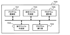
- FIG. 3 is a block diagram showing an example of a functional configuration of the network system design support program (simulation program) according to the present embodiment.
- FIG. 4 is a diagram illustrating an example of a GUI displayed on the display.
- FIG. 5 is a diagram illustrating an example of a GUI displayed on the display.
- FIG. 6 is a flowchart illustrating an example of a processing flow of the simulation apparatus according to the present embodiment.
- FIG. 7 is a diagram illustrating a configuration example of a general field network.
- FIG. 1 is a block diagram illustrating a schematic configuration of a design support system according to the present embodiment.
- This design support system is a system for supporting the design of a network system configured by joining at least one slave device on a communication bus that draws a line, tree, or star topology starting from a master device.
- This network system is an industrial field network configured by connecting ports provided in each of a master device and a slave device.
- EtherCAT registered trademark
- the ports provided in the slave device have two connection interfaces of an external bus (RJ45) and an internal bus (E-Bus).
- RJ45 external bus
- E-Bus internal bus
- the design support system of the present embodiment is not limited to the design of an EtherCAT (registered trademark) network system, and there may be other types of port connection interfaces other than external and internal.
- the design support system 1 includes a display 2 that displays a GUI (graphical user interface) for design support, a PC (personal computer) 3 that controls the GUI displayed on the display 2, and a command that allows the user to operate the GUI to the PC 3. And an input device 4 including a keyboard and a mouse for inputting.
- the design support system 1 allows a user to design a network system offline.
- the design support system 1 may be configured such that a user can input a command to an online network system by connecting to an actual device of the network system, for example, a master device (PLC).
- PLC master device
- FIG. 2 is a block diagram illustrating a schematic functional configuration of the PC 3 (simulation apparatus) according to the present embodiment.
- the PC 3 includes a storage unit 31, an acquisition unit 32, an input unit 33, a generation unit 34, and an image output unit 35.
- the storage unit 31 stores slave information data in which unique information of the slave device is described.
- the slave information data is, for example, an XML format file that describes the model number of the slave device, vendor identification information, port information provided in the slave device, and the like.
- the obtaining unit 32 obtains information on the port provided in the slave device from the slave information data stored in the storage unit 31.
- the port information includes, for example, the number of ports provided in the slave device, the type of port connection interface (internal bus, external bus, etc.), and port identification information (name, etc.).
- the input unit 33 receives a signal input from the input device 4 and inputs a command to the generation unit 34.
- the generation unit 34 generates a design support GUI in accordance with the command input from the input unit 33. Further, image data that can be displayed on the display 2 is generated based on the generated GUI data, and is output to the image output means 35.
- the GUI generated by the generation unit 34 will be described later.
- the image output unit 35 outputs the image data input from the generation unit 34 to the display 2.
- the PC 3 has a known configuration such as a CPU (not shown), memory, disk, various input / output interfaces, and a bus for connecting them. (Hard disk drive) etc.
- the acquisition unit 32 and the generation unit 34 are realized by the CPU reading and executing the network system design support program installed in the HDD or the like from the disk.
- the input unit 33 and the image output unit 35 are realized by a mouse connection terminal, a keyboard connection terminal, and a display connection terminal that are connected to a CPU or the like via a bus.
- FIG. 3 is a block diagram illustrating an example of a functional configuration of the network system design support program (simulation program) according to the present embodiment (functions realized by the CPU of the PC 3 executing the program).
- the operation of the master device is simulated by the CPU of the PC 3 executing the simulation program.
- a simulation program 700 includes a program registration unit 701, an execution file creation unit 702, a setting file creation unit 703, a program selection unit 704, a program execution unit 705, and the like.
- the program registration unit 701 causes the user to register a group of programs to be executed by the master device as a task. Specifically, the program registration unit 101 causes the user to create a task to be executed by the master device and add (register) the program to the created task.
- a plurality of tasks can be created, and priority and execution cycle can be set for each task. For example, when a priority is set for a task, the tasks are executed in order from the task with the highest priority. When an execution cycle is set for the task, the task is repeatedly executed at the set execution cycle.
- the task configuration is configured by a plurality of execution files obtained by compiling and building for each execution unit of the program and a setting file indicating the execution order of the plurality of execution files.
- execution / non-execution of the program can be switched for each execution unit.
- debugging work only the program to be checked (for example, the modified program) is compiled and built, and only the executable file created thereby is executed, so that development efficiency can be greatly improved compared to the conventional method.
- Such a configuration is realized by an execution file creation unit 702, a setting file creation unit 703, a program selection unit 704, and a program execution unit 705 described below.
- the execution file creation unit 702 creates an execution file for each program included in the task registered by the program registration unit 701. Specifically, the execution file creation unit 702 creates an execution file of the program registered by the program registration unit 701 in the minimum unit of the program. For example, when the program is a ladder program, the execution file is created in units of sections. That is, in the simulation program according to the present embodiment, an execution file is created by compiling and building for each program (or for each minimum unit of the program).
- program is a ladder program (hereinafter simply referred to as “program”), and the execution file is created in section units.
- execution file may be created in accordance with an instruction to create an execution file from the user, or may be created automatically.
- the execution file may be automatically created at the timing when the program is registered in the task or when the simulation is performed.
- execution file may be created in units of programs (units of ladder programs).
- the setting file creation unit 703 creates a setting file indicating the execution order of the execution files created by the execution file creation unit 702 for each task.
- the setting file may be created in accordance with a setting file creation instruction from the user, or may be created automatically.
- the setting file may be automatically created at the timing when the program is registered in the task or when simulation is performed.
- the execution order of the execution files may be the order in which the program is registered in the task, or may be the order specified by the user separately from the registration order.
- the program selection unit 704 causes the user to select execution / non-execution of each program included in the task registered in the program registration unit 701. Specifically, the program selection unit 704 causes the user to select execution / non-execution of each execution file created by the execution file creation unit 702. Then, the program execution unit 705 is instructed to execute / non-execute the execution file.
- execution / non-execution of the execution file may be selected for each program, or may be selected for each section (that is, for each execution file).
- execution / non-execution of all execution files corresponding to the program is selected at a time.
- the program execution unit 705 switches execution / non-execution of an execution file in accordance with an instruction from the program selection unit 704 when executing a task. Thereby, only a part of the programs included in the task (the program or section selected to be executed by the program selection unit 704) is executed. Specifically, among the execution files created by the execution file creation unit 702, only the execution files selected for execution by the program selection unit 704 are executed in the order indicated by the setting file. That is, the program execution unit 705 simulates only the operation of a part of programs (or sections) included in the task.
- FIG. 4 is a diagram illustrating an example of a GUI displayed on the display 2.
- the user can perform operations such as task creation, program registration to the task, program execution order setting, task priority setting, and task execution cycle setting. For example, the user can perform the above operation from a menu screen displayed by a predetermined operation (such as a right mouse click). Further, the above operation can be performed using a button 803 in the registration screen 801.
- the created task, the registered program, and the name of the section are displayed in a tree shape.
- the display mode is not limited to a tree shape. As long as the task and the program included in the task can be confirmed, the task may be displayed in any manner.
- the selection screen 802 displays a list of programs and a check box associated with each program in the list. Specifically, on the selection screen 802, the names of tasks, programs, and sections are displayed in a tree shape as in the registration screen 801, and a check box 804 is provided for each name (item). Are displayed in association with each other.
- a user can select execution / non-execution of a task, execution / non-execution of a program, and execution / non-execution of a section using a check box 804.
- the selection screen 802 may display the names of all programs including those not registered in the task. However, if the names of all the programs are displayed, the number of displays (the number of programs and the number of sections) may become enormous, so it is preferable to display only the names of the programs registered in the task. Accordingly, the user can easily select a program or section to be executed, and the convenience for the user is improved.
- execution / non-execution of the execution file is selected using the check box 804
- the execution file non-execution selection method is not limited to this.
- execution / non-execution of an execution file may be selected using a text box 805 as shown in FIG.
- the configuration may be such that only the execution file corresponding to the program having the name input in the text box 805 is executed (or not executed).
- the check box is used, the user can easily select execution / non-execution of the execution file.
- the registration screen 801 and the selection screen 802 are different windows, but the screen of each function is not limited thereto.
- the created task, the registered program, and the section name may be displayed in a tree shape on the registration screen 801, and a check box may be displayed in association with each name.
- the content of the task is information that is not changed immediately after being confirmed once, and is rarely confirmed during the execution of the simulation. Therefore, there is no particular problem even if it is not displayed after confirmation.
- the registration screen 801 and the selection screen 802 are different windows, only the registration screen 801 can be closed (or minimized) after the task is determined.
- the empty area can be used as an area for displaying other information necessary for the user (for example, an editor display area). As a result, the user can grasp more necessary information (for example, a moving program and its contents) during the simulation execution, and the convenience of the user is improved.
- FIG. 6 is a flowchart showing an example of the flow of processing of the simulation program according to the present embodiment.
- the program registration unit 701 causes the user to create a task (step S101).
- task A composed of programs P1, P2, and P3 is created.
- the program P1 is composed of sections S11 to S14
- the program P2 is composed of sections S21 to S22
- the program P3 is composed of sections S31 to S35.
- the task B is also created. However, the following description will be given focusing on the task A.
- the execution file creation unit 702 creates an execution file of the created task in section units (step S102).
- the setting file creation unit 703 creates a setting file (step S103).
- the registration screen 801 shows programs and sections in the order of execution. That is, in the example of FIG. 4, a setting file indicating the order of program P1 (section S11 ⁇ S12 ⁇ S13 ⁇ S14) ⁇ program P2 (section S21 ⁇ S22) ⁇ program P3 (section S31 ⁇ S32 ⁇ S33 ⁇ S34 ⁇ S35). Is created.
- the program execution unit 705 determines whether to execute the execution file to be executed (simulation target). (Step S104). Specifically, the program execution unit 705 determines whether execution is instructed for the execution target execution file. If execution is instructed (step S104: YES), the process proceeds to step S107. If execution is not instructed (step S104: NO), the process proceeds to step S105.
- the execution file of section S11 is first set as the execution target.
- the program selection unit 704 instructs execution of the execution file of the section S11.
- step S105 the program execution unit 705 executes (simulates) the execution file to be executed.
- step S105 it is determined whether or not to end the simulation (step S106). If the simulation is to be ended (step S106: YES), this flow is ended. If not (step S106: NO), the process proceeds to step S107.
- the program execution unit 705 may perform or a determination unit (not illustrated) may perform. Whether or not to end may be determined according to the presence or absence of a simulation end instruction from the user, for example. The determination may be made according to whether the task has been executed a predetermined number of cycles.
- step S107 the program execution unit 705 switches the execution target execution file to the next execution file in accordance with the setting file created in step S103. Then, the process returns to step S104.
- the execution file of section S12 is the execution target.
- step S107 If there is no next executable file (when the execution of one cycle is completed), the execution file is switched to the first execution file in the task in step S107. Then, the processing from step S104 is resumed at the set execution cycle.
- execution / non-execution of the program registered in the task is selected by the user, and only the selected program is executed.
- only a part of the programs included in the task can be executed in a small number of work steps and in a short time.
- an executable file is created for each program and only the executable file selected by the user is executed, the above work becomes unnecessary, and some programs included in the task with a small number of work steps and a short time Can only run.
- execution file is created in the minimum unit of the program
- execution / non-execution of the program can be switched in the minimum unit.
- the user can select execution / non-execution of the execution file regardless of whether the simulation is being executed. If the execution / non-execution selection state of the executable file is changed during the simulation, the changed selection is performed during the current cycle of the task that is executed periodically (for example, immediately after the selection state is changed). The simulation may be continued while reflecting the state, or the changed selected state may be reflected at the timing of starting the next cycle.
- the simulation apparatus of the present invention is a simulation apparatus that simulates the operation of the apparatus, and includes a registration unit that causes a user to register a program group executed by the device as a task, and each task included in the task registered by the registration unit. Selection means for allowing a user to select execution / non-execution of a program; and execution means for executing only a program selected to be executed by the selection means among the programs included in the task registered by the registration means. It is characterized by that.
- execution / non-execution of each program included in the task is selected by the user, and only the selected program is executed. This eliminates the need for tasks such as creating and rewriting tasks for simulation and creating an execution file for each simulation. As a result, only a part of the programs included in the task can be executed in a small number of work steps and in a short time.
- the simulation apparatus of the present invention further includes an execution file creation unit that creates an execution file for each program included in the task registered by the registration unit.
- the selection unit causes the user to select execution / non-execution of each execution file created by the execution file creation unit, and the execution unit includes the execution file created by the execution file creation unit. It is preferable to execute only the execution file whose execution is selected by the selection means. With such a configuration, an executable file is created for each program, and only the executable file selected by the user is executed. Therefore, creation and rewriting of tasks for simulation and execution files for each simulation are executed. A work such as creation becomes unnecessary, and only an execution file corresponding to a part of programs included in the task can be executed in a short work man-hour and in a short time.
- the execution file creation means creates an execution file in a minimum unit of a program.
- execution / non-execution of a program can be switched in a minimum unit.
- the screen for allowing the user to select execution / non-execution of the program preferably includes a list of programs and a check box associated with each program in the list.
- the screen for allowing the user to register the task and the screen for allowing the user to select execution / non-execution of the program are different windows.
- the content of the task is information that is not changed immediately after being confirmed once, and is rarely confirmed during the execution of the simulation. Therefore, there is no particular problem even if it is not displayed after confirmation.
- the screen that allows the user to register the task (registration screen) and the screen that allows the user to select whether to execute or not execute the program (selection screen) are different windows, only the registration screen is closed (or minimized) after the task is confirmed.
- the vacant area can be used as an area for displaying other information necessary for the user. As a result, the user can grasp more necessary information during the simulation execution, and the convenience of the user is improved.
- the present invention may be regarded as a simulation apparatus having at least a part of the above means, or a simulation method including at least a part of the above process, or a simulation program for realizing such a method and a program thereof are recorded. It can also be regarded as a recording medium.
- a simulation apparatus having at least a part of the above means, or a simulation method including at least a part of the above process, or a simulation program for realizing such a method and a program thereof are recorded. It can also be regarded as a recording medium.
Landscapes
- Engineering & Computer Science (AREA)
- Theoretical Computer Science (AREA)
- Computer Hardware Design (AREA)
- Quality & Reliability (AREA)
- Physics & Mathematics (AREA)
- General Engineering & Computer Science (AREA)
- General Physics & Mathematics (AREA)
- Debugging And Monitoring (AREA)
- Stored Programmes (AREA)
Abstract
少ない作業工数且つ短時間で、タスクに含まれる一部のプログラムのみを実行可能とする技術を提供する。本発明のシミュレーション装置は、装置の動作をシミュレートするシミュレーション装置であって、前記装置で実行するプログラム群をタスクとしてユーザに登録させる登録手段と、前記登録手段で登録されたタスクに含まれる各プログラムの実行/非実行をユーザに選択させる選択手段と、前記登録手段で登録されたタスクに含まれるプログラムのうち、前記選択手段で実行が選択されたプログラムのみを実行する実行手段と、を有することを特徴とする。
Description
本発明は、シミュレーション装置に関する。
FA(Factory Automation)においては、工場内に設置される生産設備のデータ収集及び制御を行う各種のスレーブ装置と、複数のスレーブ装置を集中管理するマスター装置と、を通信バスを介して接続したフィールドネットワークにより生産設備の制御が行われる。マスター装置は、例えば、複数のプログラムからなるタスクを実行することで、接続された複数のスレーブ装置を制御したり、各スレーブ装置から情報を取得したりする。
図7は、フィールドネットワークの構成例を示す図である。図7において、フィールドネットワーク100は、マスター装置200(PLC:Programmable Logic Controller)と複数のスレーブ装置300とがケーブル400や装置に備わるI/Oユニット500を介して直接的又は間接的に接続されることにより形成される。スレーブ装置300には、電源ユニット,モータユニット,カウンタユニット,画像ユニット,通信ユニット,I/Oユニット等がある。通信バスのトポロジーは、フィールドネットワークの規格により、ライン、デイジーチェーン、ツリー、スターなど種々のトポロジーをとり得る。
また、マスター装置200には、ユーザがマスター装置200の動作設定、フィールドネットワーク100の動作状態の表示、ネットワークシステムの設計(例えば、マスター装置とスレーブ装置の接続構成の決定や、マスター装置で実行するタスクの作成)などを行うための管理装置600が接続されることもある。管理装置600は設定ツールがインストールされたパーソナルコンピュータなどにより構成される。
従来、マスター装置で実行するタスクの一般的な作成手順は以下のとおりであった。(1)まず、管理装置600等に実装されている開発環境(プログラミングツール)を用いて、マスター装置で実行させる複数のプログラムコードを作成する。プログラムは、例えば、ラダー言語、SFC言語、ストラクチャードテキスト等で記述される。最近では、複数の言語が混在していることも多い。
(2)作成した複数のプログラムをまとめてコンパイル・ビルドすることにより、1つの実行ファイル(タスク)を作成する。
(3)作成したタスクを管理装置600等に実装されているシミュレータで実行(シミュレーション)し、該タスクに不具合が無いこと(即ち、マスター装置が意図した動作を行うこと)を確認する。
(4)不具合が発見されたら(2)に戻りプログラムを修正し、(3)のシミュレーションを実行する。
(5)完成した実行ファイル(タスク)をマスター装置のメモリにインストールする。
(2)作成した複数のプログラムをまとめてコンパイル・ビルドすることにより、1つの実行ファイル(タスク)を作成する。
(3)作成したタスクを管理装置600等に実装されているシミュレータで実行(シミュレーション)し、該タスクに不具合が無いこと(即ち、マスター装置が意図した動作を行うこと)を確認する。
(4)不具合が発見されたら(2)に戻りプログラムを修正し、(3)のシミュレーションを実行する。
(5)完成した実行ファイル(タスク)をマスター装置のメモリにインストールする。
しかしながら、上記従来の手順では、シミュレーションにおいてタスクに不具合が見つかる度に、プログラムを修正し、コンパイル・ビルドしてタスクを作成して、再度シミュレーションを行うというデバッグ作業を繰り返さなければならない。大きいプログラムではコンパイル・ビルドに数分~数十分も要する場合があり、デバッグ作業に要する時間の長大化が問題となっていた。また、シミュレーションでは、不具合箇所の確認のためだけに、タスク全体が実行されるため、非効率的であった。近年では、プログラム規模は増大の傾向にあるため、これらの問題は特に深刻になってきている。
上記課題を解決する方法として、動作の確認対象であるプログラムのみからなるタスク(例えば、特許文献1に開示の画像処理サブルーチン候補セットや、特許文献2に開示のデバッグ対象タスク)を作成する方法が考えられる。しかしながら、そのような方法を用いたとしても、タスクを実行(シミュレーション)する度に、動作の確認対象のプログラム群をまとめてコンパイル・ビルドして1つの実行ファイル(タスク)を作成しなければならないため、シミュレーション全体の時間が非常に長くなってしまう。また、シミュレーションを行う際に、ユーザはタスクに含めるプログラムを決定(変更)しなければならないため、ユーザの作業工数が増してしまう。タスクに含めるプログラムの組み合わせが多い場合には、上記問題(シミュレーション全体の長時間化、ユーザの作業工数の増加)は顕著に現れる。
本発明は、少ない作業工数且つ短時間で、タスクに含まれる一部のプログラムのみを実行可能とする技術を提供することを目的とする。
上記目的を達成するために、本発明は以下の構成を採用する。
本発明のシミュレーション装置は、装置の動作をシミュレートするシミュレーション装置であって、前記装置で実行するプログラム群をタスクとしてユーザに登録させる登録手段と、前記登録手段で登録されたタスクに含まれる各プログラムの実行/非実行をユーザに選択させる選択手段と、前記登録手段で登録されたタスクに含まれるプログラムのうち、前記選択手段で実行が選択されたプログラムのみを実行する実行手段と、を有することを特徴とする。
本発明のシミュレーション装置では、タスクに含まれる各プログラムの実行/非実行がユーザに選択され、選択されたプログラムのみが実行される。これにより、シミュレーションのためのタスクの作成や書き換え、及び、シミュレーション毎の実行ファイルの作成といった作業が不要となる。その結果、少ない作業工数且つ短時間で、タスクに含まれる一部のプログラムのみを実行することが可能となる。
また、本発明は、上記手段の少なくとも一部を有するシミュレーション装置として捉えてもよいし、上記処理の少なくとも一部を含むシミュレーション方法、または、かかる方法を実現するためのシミュレーションプログラムやそのプログラムを記録した記録媒体として捉えることもできる。なお、上記手段及び処理の各々は可能な限り互いに組み合わせて本発明を構成することができる。
本発明によれば、少ない作業工数且つ短時間で、タスクに含まれる一部のプログラムのみを実行することができる。
(システム構成)
図1は、本実施例に係る設計支援システムの概略構成を示すブロック図である。この設計支援システムは、マスター装置を起点としてライン、ツリー、又はスタートポロジを描く通信バス上に少なくとも1つのスレーブ装置が加入して構成されるネットワークシステムの設計を支援するためのシステムである。このネットワークシステムは、マスター装置及びスレーブ装置の各々に備わるポート同士を接続して構成される産業用のフィールドネットワークであり、例えばEtherCAT(登録商標)規格のネットワークシステムを例示できる。
図1は、本実施例に係る設計支援システムの概略構成を示すブロック図である。この設計支援システムは、マスター装置を起点としてライン、ツリー、又はスタートポロジを描く通信バス上に少なくとも1つのスレーブ装置が加入して構成されるネットワークシステムの設計を支援するためのシステムである。このネットワークシステムは、マスター装置及びスレーブ装置の各々に備わるポート同士を接続して構成される産業用のフィールドネットワークであり、例えばEtherCAT(登録商標)規格のネットワークシステムを例示できる。
EtherCAT(登録商標)のネットワークシステムでは、スレーブ装置に備わるポートには外部バス(RJ45)及び内部バス(E-Bus)の2つの接続インターフェースがある。なお、本実施例の設計支援システムは、EtherCAT(登録商標)ネットワークシステムの設計に限定されるものではなく、ポートの接続インターフェースには外部、内部以外の種類があってもよい。
設計支援システム1は、設計支援用のGUI(グラフィカルユーザインターフェース)を表示するディスプレイ2と、ディスプレイ2に表示するGUIを制御するPC(パーソナルコンピュータ)3と、ユーザがGUIを操作するコマンドをPC3に入力するためのキーボードやマウスから構成される入力装置4と、を有する。設計支援システム1により、ユーザは、オフラインでネットワークシステムの設計を行うことができる。なお、設計支援システム1は、ネットワークシステムの実機、例えばマスター装置(PLC)に接続することにより、オンラインのネットワークシステムに対しユーザがコマンドを入力することが可能に構成されていてもよい。
(装置構成)
図2は、本実施形態に係るPC3(シミュレーション装置)の概略の機能構成を示すブロック図である。PC3は、記憶手段31,取得手段32、入力手段33、生成手段34、画像出力手段35を有する。
図2は、本実施形態に係るPC3(シミュレーション装置)の概略の機能構成を示すブロック図である。PC3は、記憶手段31,取得手段32、入力手段33、生成手段34、画像出力手段35を有する。
記憶手段31は、スレーブ装置の固有情報が記述されたスレーブ情報データを記憶する。スレーブ情報データは、例えば、XML形式のファイルで、スレーブ装置の型番、ベンダーの識別情報、スレーブ装置に備わるポートの情報などが記述されている。
取得手段32は、記憶手段31に記憶されているスレーブ情報データから、スレーブ装置に備わるポートの情報を取得する。ポートの情報とは、例えば、スレーブ装置に備わるポートの個数、ポートの接続インターフェースの種類(内部バス、外部バスなど)、ポートの識別情報(名称など)を含む。
入力手段33は、入力装置4からの信号入力を受け付け、生成手段34にコマンドを入力する。
生成手段34は、入力手段33から入力されるコマンドに応じて、設計支援用のGUIを生成する。また、生成したGUIのデータに基づきディスプレイ2に表示可能な画像データを生成し、画像出力手段35へ出力する。生成手段34が生成するGUIについては後述する。
画像出力手段35は、生成手段34から入力された画像データをディスプレイ2へ出力する。
PC3は不図示のCPU、メモリ、ディスク、各種入出力インターフェース、これらを接続するバスなど公知の構成を備え、例えば、記憶手段31は、CPUとバスを介して接続されるROM、RAM、或いはHDD(ハードディスクディスクドライブ)などにより実現される。取得手段32や生成手段34は、HDDなどにインストールされたネットワークシステム設計支援プログラムをCPUがディスクから読み込み、実行することによって実現される。入力手段33や画像出力手段35は、バスを介してCPUなどに接続するマウス接続端子、キーボード接続端子、ディスプレイ接続端子により実現される。
(プログラム構成)
図3は、本実施形態に係るネットワークシステム設計支援プログラム(シミュレーションプログラム)の機能構成(PC3のCPUが該プログラムを実行することにより実現される機能)の一例を示すブロック図である。本実施形態では、PC3のCPUが上記シミュレーションプログラムを実行することにより、マスター装置の動作がシミュレートされる。
図3は、本実施形態に係るネットワークシステム設計支援プログラム(シミュレーションプログラム)の機能構成(PC3のCPUが該プログラムを実行することにより実現される機能)の一例を示すブロック図である。本実施形態では、PC3のCPUが上記シミュレーションプログラムを実行することにより、マスター装置の動作がシミュレートされる。
図3に示すように、本実施形態に係るシミュレーションプログラム700は、プログラム登録部701、実行ファイル作成部702、設定ファイル作成部703、プログラム選択部704、プログラム実行部705などを有する。
プログラム登録部701は、マスター装置で実行するプログラム群をタスクとしてユーザに登録させる。具体的には、プログラム登録部101は、ユーザに、マスター装置で実行するタスクを作成させ、作成したタスクへプログラムを追加(登録)させる。なお、タスクは複数作成することができ、各タスクに優先度や実行周期を設定することができる。例えば、タスクに優先度が設定されている場合には、優先度が高いタスクから順に実行される。また、タスクに実行周期が設定されている場合には、タスクは、設定されている実行周期で繰り返し実行される。
前述のように、従来は、デバッグ作業のために毎回全てのプログラムをコンパイル・ビルドし、タスク全体を実行する必要があった。そのため、一連のシミュレーションを完了するまでに長時間要する等、開発効率の低下が問題となっていた。
そこで、本実施形態では、タスクの構成を、プログラムの実行単位毎にコンパイル・ビルドして得られる複数の実行ファイルと、該複数の実行ファイルの実行順序を示す設定ファイルとからなる構成とした。それにより、実行単位毎にプログラムの実行/非実行を切り換えることが可能となる。そのため、デバッグ作業では、確認対象のプログラム(例えば修正したプログラム)のみをコンパイル・ビルドし、それにより作成された実行ファイルのみを実行することで、従来に比べ開発効率を格段に向上することができる。なお、そのような構成は、以下で説明する実行ファイル作成部702、設定ファイル作成部703、プログラム選択部704、プログラム実行部705により実現される。
実行ファイル作成部702は、プログラム登録部701で登録されたタスクに含まれるプログラム毎に実行ファイルを作成する。具体的には、実行ファイル作成部702は、プログラム登録部701で登録されたプログラムの実行ファイルを、プログラムの最小単位で作成する。例えば、プログラムがラダープログラムの場合には、実行ファイルはセクション単位で作成される。即ち、本実施形態に係るシミュレーションプログラムでは、プログラム毎(又は、プログラムの最小単位毎)にコンパイル・ビルドして実行ファイルが作成される。
なお、本実施形態では、プログラムがラダープログラム(以後、単に“プログラム”と記載)であり、実行ファイルはセクション単位で作成されるものとして説明する。
なお、実行ファイルは、ユーザからの実行ファイル作成の指示に応じて作成されてもよいし、自動で作成されてもよい。例えば、タスクにプログラムが登録されたタイミングや、シミュレーションを行うタイミングで実行ファイルが自動で作成されてもよい。
また、実行ファイルは、プログラム単位(ラダープログラム単位)で作成されてもよい。
設定ファイル作成部703は、タスク毎に、実行ファイル作成部702で作成された実行ファイルの実行順序を示す設定ファイルを作成する。
なお、設定ファイルは、ユーザからの設定ファイル作成の指示に応じて作成されてもよいし、自動で作成されてもよい。例えば、タスクにプログラムが登録されたタイミングや、シミュレーションを行うタイミングで、設定ファイルが自動で作成されてもよい。実行ファイルの実行順序は、タスクにプログラムが登録された順序であってもよいし、登録順序とは別にユーザによって指定された順序であってもよい。
プログラム選択部704は、プログラム登録部701で登録されたタスクに含まれる各プログラムの実行/非実行をユーザに選択させる。具体的には、プログラム選択部704は、実行ファイル作成部702で作成された各実行ファイルの実行/非実行をユーザに選択させる。そして、実行ファイルの実行/非実行をプログラム実行部705へ指示する。
なお、実行ファイルの実行/非実行は、プログラム毎に選択させてもよいし、セクション毎(即ち、実行ファイル毎)に選択させてもよい。プログラムが選択された場合には、そのプログラムに対応する全ての実行ファイルの実行/非実行が一度に選択される。
プログラム実行部705は、タスクを実行する際に、プログラム選択部704からの指示に応じて、実行ファイルの実行/非実行を切り換える。それにより、タスクに含まれる全てのプログラムのうち、一部のプログラム(プログラム選択部704で実行が選択されたプログラムまたはセクション)のみが実行される。具体的には、実行ファイル作成部702で作成された実行ファイルのうち、プログラム選択部704で実行が選択された実行ファイルのみが、設定ファイルで示される順番で実行される。即ち、プログラム実行部705により、タスクに含まれる一部のプログラム(またはセクション)による動作だけがシミュレートされる。
(表示例)
ディスプレイ2に表示するGUIの一例について、図4を用いて説明する。図4は、ディスプレイ2に表示するGUIの一例を示す図である。
ディスプレイ2に表示するGUIの一例について、図4を用いて説明する。図4は、ディスプレイ2に表示するGUIの一例を示す図である。
図4の符号801は、タスクをユーザに登録させる画面(ウィンドウ)、即ち、プログラム登録部701が生成、表示する登録画面を示す。ユーザは、登録画面801で、タスクの作成、タスクへのプログラムの登録、プログラムの実行順序の設定、タスクの優先度の設定、タスクの実行周期の設定などの操作を行うことができる。ユーザは、例えば、所定の操作(マウスの右クリックなど)により表示されるメニュー画面から上記操作を行うことができる。また、登録画面801内のボタン803を用いて、上記操作を行うことができる。そして、登録画面801内には、作成されたタスク、登録されたプログラム及びそのセクションの名称(識別子を含む)がツリー状に表示される。なお、表示態様はツリー状に限らない。タスクとそのタスクに含まれるプログラムが確認できればどのように表示されていてもよい。
図4の符号802は、実行ファイルの実行/非実行をユーザに選択させる画面、即ち、プログラム選択部704が生成、表示する選択画面を示す。図4の例では、選択画面802には、プログラムのリストと、リスト内のプログラム毎に対応付けられたチェックボックスが表示される。具体的には、選択画面802には、登録画面801と同様に、タスク、プログラム、及び、セクションの名称がツリー状に表示されており、且つ、各名称(項目)に、それぞれ、チェックボックス804が対応づけて表示されている。ユーザは、チェックボックス804を用いて、タスクの実行/非実行、プログラムの実行/非実行、及び、セクションの実行/非実行を選択することができる。本実施形態では、チェックが入っているタスク、プログラム、セクションに対応する実行ファイルが実行されるものとするが、チェックが入っているタスク、プログラム、セクションに対応する実行ファイルを実行しない構成であってももちろんよい。
なお、選択画面802には、タスクに登録されていないプログラムも含めた全てのプログラムの名称が表示されていてもよい。但し、全てのプログラムの名称を表示すると、表示数(プログラム数やセクション数)が膨大となる虞があるため、タスクに登録されたプログラムの名称のみを表示することが好ましい。それにより、ユーザは実行するプログラムやセクションを容易に選択することが可能となり、ユーザの利便性が向上する。
また、図4の例では、チェックボックス804を用いて実行ファイルの実行/非実行が選択される場合を示したが、実行ファイルの実行/非実行の選択方法はこれに限らない。例えば、図5に示すようなテキストボックス805を用いて実行ファイルの実行/非実行が選択されてもよい。その場合には、テキストボックス805に入力された名称のプログラムに対応する実行ファイルのみを実行する(または実行しない)構成とすればよい。但し、チェックボックスを用いれば、ユーザは容易に実行ファイルの実行/非実行を選択することができる。
また、図4の例では、登録画面801と選択画面802が互いに異なるウィンドウである場合について説明したが、各機能の画面はこれに限らない。例えば、登録画面801に作成したタスク、登録したプログラム、及び、セクションの名称をツリー状に表示し、各名称に、それぞれ、チェックボックスが対応づけて表示されてもよい。
但し、シミュレーション実行中には、動いているプログラムの内容をエディタを用いて確認するのが一般的であり、必要な情報の表示領域を大きくするためにも、余計なウィンドウは極力表示しないことが好ましい。タスクの内容は、一度確定した後すぐには変更されない情報であり、シミュレーション実行中に確認されることは少ないため、確定後には表示されていなくても特に問題はない。登録画面801と選択画面802を互いに異なるウィンドウとすれば、タスクの確定後に登録画面801のみを閉じる(または最小化する)ことができる。そして、空いた領域をユーザに必要な他の情報を表示する領域(例えば、エディタの表示領域)として使用することができる。その結果、ユーザは、シミュレーション実行中に、必要なより多くの情報(例えば、動いているプログラム、及び、その内容)を把握することが可能となり、ユーザの利便性が向上する。
(処理フロー)
本実施形態に係るシミュレーションプログラムの処理の流れについて図4,6を用いて説明する。図6は、本実施形態に係るシミュレーションプログラムの処理の流れの一例を示すフローチャートである。
本実施形態に係るシミュレーションプログラムの処理の流れについて図4,6を用いて説明する。図6は、本実施形態に係るシミュレーションプログラムの処理の流れの一例を示すフローチャートである。
まず、プログラム登録部701が、ユーザにタスクを作成させる(ステップS101)。
図4の例では、プログラムP1,P2,P3からなるタスクAが作成される。プログラムP1は、セクションS11~S14からなり、プログラムP2は、セクションS21~S22からなり、プログラムP3は、セクションS31~S35からなる。なお、図4の例ではタスクBも作成されているが、以下ではタスクAに注目して説明を行うものとする。
次に、実行ファイル作成部702が、作成されたタスクの実行ファイルを、セクション単位で作成する(ステップS102)。
図4の例では、セクションS11~S14、セクションS21~S22、セクションS31~S35の計11個の実行ファイルが作成される。
そして、設定ファイル作成部703が、設定ファイルを作成する(ステップS103)。
図4の例では、登録画面801には、プログラム及びセクションが実行順に示されている。即ち、図4の例では、プログラムP1(セクションS11→S12→S13→S14)→プログラムP2(セクションS21→S22)→プログラムP3(セクションS31→S32→S33→S34→S35)の順を示す設定ファイルが作成される。
次に、ステップS103で作成された設定ファイルと、プログラム選択部704からの実行/非実行の指示とから、プログラム実行部705が実行対象(シミュレーション対象)の実行ファイルを実行するか否かを判断する(ステップS104)。具体的には、プログラム実行部705は、実行対象の実行ファイルに対して実行が指示されているか否かを判断する。実行が指示されている場合には(ステップS104:YES)、ステップS107へ処理が進められ、実行が指示されていない場合には(ステップS104:NO)、ステップS105へ処理が進められる。
図4の例では、初めにセクションS11の実行ファイルが実行対象とされる。また、図4の例では、選択画面802において、セクションS11のチェックボックスにチェックが入っているため、プログラム選択部704からセクションS11の実行ファイルの実行が指示される。
ステップS105では、プログラム実行部705が、実行対象の実行ファイルを実行(シミュレート)する。
(ステップS105の)次に、シミュレーションを終了するか否かが判断され(ステップS106)、終了する場合には(ステップS106:YES)、本フローは終了され、終了しない場合には(ステップS106:NO)、ステップS107へ処理が進められる。なお、終了するか否かの判定は、どの機能が行ってもよい。例えば、プログラム実行部705が行ってもよいし、不図示の判定部が行ってもよい。終了するか否かは、例えば、ユーザからのシミュレーション終了の指示の有無に応じて判断すればよい。タスクが所定サイクル数実行されたか否かに応じて判断してもよい。
ステップS107では、プログラム実行部705が、ステップS103で作成された設定ファイルに応じて、実行対象の実行ファイルを次の実行ファイルに切り替える。そして、ステップS104へ処理が戻される。
図4の例では、セクションS12の実行ファイルが実行対象とされる。
なお、次の実行ファイルが無い場合(1サイクルの実行が終了した場合)には、ステップS107では、実行ファイルがタスク内の最初の実行ファイルに切り替えられる。そして、設定されている実行周期でステップS104からの処理が再開される。
以上の処理により、タスクに含まれる全てのプログラムのうち、一部のプログラム(プログラム選択部704で実行が選択されたプログラムまたはセクション)のみが実行される。
以上述べたように、本実施形態によれば、タスクに登録したプログラムの実行/非実行がユーザに選択され、選択されたプログラムのみが実行される。これにより、シミュレーションのためのタスクの作成や書き換え、及び、シミュレーション毎の実行ファイルの作成といった作業が不要となる。その結果、少ない作業工数且つ短時間で、タスクに含まれる一部のプログラムのみを実行することができる。具体的には、プログラム毎に実行ファイルが作成され、ユーザに選択された実行ファイルのみが実行されるため、上記作業が不要となり、少ない作業工数且つ短時間で、タスクに含まれる一部のプログラムのみを実行することができる。
また、本実施形態によれば、実行ファイルはプログラムの最小単位で作成されるため、最小単位でプログラムの実行/非実行を切り換えることができる。その結果、ユーザが実行したい箇所のみをより細かく指定して実行することが可能となるため、より短時間でシミュレーションを完了することが可能となる。
また、本実施形態によれば、ユーザは、シミュレーションの実行中か否かに拘わらず、実行ファイルの実行/非実行を選択することができる。シミュレーションの実行中に実行ファイルの実行/非実行の選択状態が変更された場合には、周期的に実行されるタスクの現在のサイクル中(例えば、選択状態の変更直後)に、変更後の選択状態を反映してシミュレーションを続けてもよいし、次のサイクルを開始するタイミングで変更後の選択状態を反映してもよい。
なお、本実施形態では、マスター装置の動作をシミュレートする場合について説明したが、シミュレーションの対象とする装置はマスター装置に限らない。どのような装置の動作をシミュレートする場合であっても、本実施形態に係るシミュレーション装置を用いることができる。
本発明のシミュレーション装置は、装置の動作をシミュレートするシミュレーション装置であって、前記装置で実行するプログラム群をタスクとしてユーザに登録させる登録手段と、前記登録手段で登録されたタスクに含まれる各プログラムの実行/非実行をユーザに選択させる選択手段と、前記登録手段で登録されたタスクに含まれるプログラムのうち、前記選択手段で実行が選択されたプログラムのみを実行する実行手段と、を有することを特徴とする。
本発明のシミュレーション装置では、タスクに含まれる各プログラムの実行/非実行がユーザに選択され、選択されたプログラムのみが実行される。これにより、シミュレーションのためのタスクの作成や書き換え、及び、シミュレーション毎の実行ファイルの作成といった作業が不要となる。その結果、少ない作業工数且つ短時間で、タスクに含まれる一部のプログラムのみを実行することが可能となる。
また、本発明のシミュレーション装置は、前記登録手段で登録されたタスクに含まれるプログラム毎に実行ファイルを作成する実行ファイル作成手段を更に有することが好ましい。そして、前記選択手段は、前記実行ファイル作成手段で作成された各実行ファイルの実行/非実行をユーザに選択させ、前記実行手段は、前記実行ファイル作成手段で作成された実行ファイルのうち、前記選択手段で実行が選択された実行ファイルのみを実行することが好ましい。このような構成にすることにより、プログラム毎に実行ファイルが作成され、ユーザに選択された実行ファイルのみが実行されるため、シミュレーションのためのタスクの作成や書き換え、及び、シミュレーション毎の実行ファイルの作成といった作業が不要となり、少ない作業工数且つ短時間で、タスクに含まれる一部のプログラムに対応する実行ファイルのみを実行することができる。
また、前記実行ファイル作成手段は、実行ファイルをプログラムの最小単位で作成することが好ましい。このような構成にすることにより、最小単位でプログラムの実行/非実行を切り換えることができる。その結果、ユーザが実行したい箇所のみをより細かく指定して実行することが可能となるため、より短時間でシミュレーションを完了することが可能となる。
また、前記プログラムの実行/非実行をユーザに選択させる画面は、プログラムのリストと、リスト内のプログラム毎に対応付けられたチェックボックスとを有することが好ましい。このような構成にすることにより、ユーザは実行するプログラムを容易に選択することが可能となり、ユーザの利便性が向上する。
また、前記タスクをユーザに登録させる画面と前記プログラムの実行/非実行をユーザに選択させる画面は、互いに異なるウィンドウであることが好ましい。タスクの内容は、一度確定した後すぐには変更されない情報であり、シミュレーション実行中に確認されることは少ないため、確定後には表示されていなくても特に問題はない。タスクをユーザに登録させる画面(登録画面)とプログラムの実行/非実行をユーザに選択させる画面(選択画面)を、互いに異なるウィンドウとすれば、タスクの確定後に登録画面のみを閉じる(または最小化する)ことができ、空いた領域をユーザに必要な他の情報を表示する領域として使用することができる。その結果、ユーザは、シミュレーション実行中に、必要なより多くの情報を把握することが可能となり、ユーザの利便性が向上する。
また、本発明は、上記手段の少なくとも一部を有するシミュレーション装置として捉えてもよいし、上記処理の少なくとも一部を含むシミュレーション方法、または、かかる方法を実現するためのシミュレーションプログラムやそのプログラムを記録した記録媒体として捉えることもできる。なお、上記手段及び処理の各々は可能な限り互いに組み合わせて本発明を構成することができる。
1 設計支援システム
2 ディスプレイ
3 PC
4 入力装置
31 記憶手段
32 取得手段
33 入力手段
34 生成手段
35 画像出力手段
100 フィールドネットワーク
200 マスター装置
300 スレーブ装置
400 ケーブル
500 ユニット
600 管理装置
700 シミュレーションプログラム
701 プログラム登録部
702 実行ファイル作成部
703 設定ファイル作成部
704 プログラム選択部
705 プログラム実行部
801 登録画面
802 選択画面
803 ボタン
804 チェックボックス
805 テキストボックス
2 ディスプレイ
3 PC
4 入力装置
31 記憶手段
32 取得手段
33 入力手段
34 生成手段
35 画像出力手段
100 フィールドネットワーク
200 マスター装置
300 スレーブ装置
400 ケーブル
500 ユニット
600 管理装置
700 シミュレーションプログラム
701 プログラム登録部
702 実行ファイル作成部
703 設定ファイル作成部
704 プログラム選択部
705 プログラム実行部
801 登録画面
802 選択画面
803 ボタン
804 チェックボックス
805 テキストボックス
Claims (8)
- 装置の動作をシミュレートするシミュレーション装置であって、
前記装置で実行するプログラム群をタスクとしてユーザに登録させる登録手段と、
前記登録手段で登録されたタスクに含まれる各プログラムの実行/非実行をユーザに選択させる選択手段と、
前記登録手段で登録されたタスクに含まれるプログラムのうち、前記選択手段で実行が選択されたプログラムのみを実行する実行手段と、
を有することを特徴とするシミュレーション装置。 - 前記登録手段で登録されたタスクに含まれるプログラム毎に実行ファイルを作成する実行ファイル作成手段を更に有し、
前記選択手段は、前記実行ファイル作成手段で作成された各実行ファイルの実行/非実行をユーザに選択させ、
前記実行手段は、前記実行ファイル作成手段で作成された実行ファイルのうち、前記選択手段で実行が選択された実行ファイルのみを実行する
ことを特徴とする請求項1に記載のシミュレーション装置。 - 前記実行ファイル作成手段は、実行ファイルをプログラムの最小単位で作成する
ことを特徴とする請求項2に記載のシミュレーション装置。 - 前記プログラムの実行/非実行をユーザに選択させる画面は、プログラムのリストと、リスト内のプログラム毎に対応付けられたチェックボックスとを有する
ことを特徴とする請求項1~3のうちいずれか1項に記載のシミュレーション装置。 - 前記タスクをユーザに登録させる画面と前記プログラムの実行/非実行をユーザに選択させる画面は、互いに異なるウィンドウである
ことを特徴とする請求項1~4のうちいずれか1項に記載のシミュレーション装置。 - コンピュータに装置の動作をシミュレートさせるためのシミュレーションプログラムであって、
コンピュータに、
前記装置で実行するプログラム群をタスクとしてユーザに登録させる登録ステップと、
前記登録ステップで登録されたタスクに含まれる各プログラムの実行/非実行をユーザに選択させる選択ステップと、
前記登録ステップで登録されたタスクに含まれるプログラムのうち、前記選択ステップで実行が選択されたプログラムのみを実行する実行ステップと、
を実行させるためのシミュレーションプログラム。 - 請求項6に記載のシミュレーションプログラムを記録した、コンピュータで読み取り可能な記録媒体。
- 装置の動作をシミュレートするシミュレーション方法であって、
コンピュータが、前記装置で実行するプログラム群をタスクとしてユーザに登録させる登録ステップと、
コンピュータが、前記登録ステップで登録されたタスクに含まれる各プログラムの実行/非実行をユーザに選択させる選択ステップと、
コンピュータが、前記登録ステップで登録されたタスクに含まれるプログラムのうち、前記選択ステップで実行が選択されたプログラムのみを実行する実行ステップと、
を有することを特徴とするシミュレーション方法。
Applications Claiming Priority (2)
| Application Number | Priority Date | Filing Date | Title |
|---|---|---|---|
| JP2011-056382 | 2011-03-15 | ||
| JP2011056382 | 2011-03-15 |
Publications (1)
| Publication Number | Publication Date |
|---|---|
| WO2012124153A1 true WO2012124153A1 (ja) | 2012-09-20 |
Family
ID=46830261
Family Applications (1)
| Application Number | Title | Priority Date | Filing Date |
|---|---|---|---|
| PCT/JP2011/056925 Ceased WO2012124153A1 (ja) | 2011-03-15 | 2011-03-23 | シミュレーション装置 |
Country Status (1)
| Country | Link |
|---|---|
| WO (1) | WO2012124153A1 (ja) |
Citations (3)
| Publication number | Priority date | Publication date | Assignee | Title |
|---|---|---|---|---|
| JPH08286901A (ja) * | 1995-04-14 | 1996-11-01 | Yamatake Honeywell Co Ltd | ソフトウエア部品の再利用システム |
| JP2006107378A (ja) * | 2004-10-08 | 2006-04-20 | Advanced Telecommunication Research Institute International | 設計支援装置 |
| JP2010157108A (ja) * | 2008-12-26 | 2010-07-15 | Canon Inc | ソフトウエア評価方法及びそれを実現する情報処理装置 |
-
2011
- 2011-03-23 WO PCT/JP2011/056925 patent/WO2012124153A1/ja not_active Ceased
Patent Citations (3)
| Publication number | Priority date | Publication date | Assignee | Title |
|---|---|---|---|---|
| JPH08286901A (ja) * | 1995-04-14 | 1996-11-01 | Yamatake Honeywell Co Ltd | ソフトウエア部品の再利用システム |
| JP2006107378A (ja) * | 2004-10-08 | 2006-04-20 | Advanced Telecommunication Research Institute International | 設計支援装置 |
| JP2010157108A (ja) * | 2008-12-26 | 2010-07-15 | Canon Inc | ソフトウエア評価方法及びそれを実現する情報処理装置 |
Similar Documents
| Publication | Publication Date | Title |
|---|---|---|
| JP5120473B2 (ja) | ネットワークシステムの設計支援装置 | |
| JP5506822B2 (ja) | プログラム作成支援装置 | |
| US9501595B2 (en) | Graphical design verification environment generator | |
| US9176490B2 (en) | Control program generation device, control program generation program, and control program generation method | |
| CN115840421A (zh) | 开发工业控制编程的系统、对工业系统编程的方法和介质 | |
| US8793668B2 (en) | Protocol independent programming environment | |
| CN115053209B (zh) | 用于在工程系统中生成工程图的方法和系统 | |
| KR101772785B1 (ko) | 프로그램 그래프 표시 장치, 프로그램 그래프 표시 방법 및 프로그램 그래프 표시 프로그램을 기록한 컴퓨터 판독 가능한 기록 매체 | |
| CN118938791A (zh) | 基于仓储物流产线的plc虚拟调试方法和系统 | |
| JP5498446B2 (ja) | ラダープログラム作成装置およびラダープログラム作成方法 | |
| US20200042336A1 (en) | Method and system for simulating a robotic program of an industrial robot | |
| KR20150066377A (ko) | Devs 기반의 시뮬레이션 프레임워크 시스템 및 이를 이용한 시뮬레이션 방법 | |
| JPH0854907A (ja) | 検証支援システム | |
| EP3848866A1 (en) | Method and system for managing engineering workflow in a cloud computing environment | |
| WO2012104959A1 (ja) | モーションsfcプログラム部品作成装置 | |
| EP4148584A1 (en) | Method and system for generating and optimizing test cases for an engineering program | |
| JP7238678B2 (ja) | 情報処理装置、サポートプログラムおよびサポートシステム | |
| US12530522B2 (en) | Method and system for generating an automation engineering project in a technical installation using multidisciplinary approach | |
| JP5212508B2 (ja) | デバッグ装置 | |
| WO2012124153A1 (ja) | シミュレーション装置 | |
| CN112204480B (zh) | 信息处理装置以及计算机可读记录介质 | |
| US12536348B1 (en) | Systems and methods for analyzing variant configurations of simulation models | |
| US12420408B1 (en) | Human machine interface recipe building system for a robotic manufacturing system | |
| JP7631921B2 (ja) | 開発支援装置、開発支援方法および開発支援プログラム | |
| JP2003140714A (ja) | 図形言語プログラム作成プログラム、及び図形言語プログラム作成装置 |
Legal Events
| Date | Code | Title | Description |
|---|---|---|---|
| 121 | Ep: the epo has been informed by wipo that ep was designated in this application |
Ref document number: 11860752 Country of ref document: EP Kind code of ref document: A1 |
|
| NENP | Non-entry into the national phase |
Ref country code: DE |
|
| 122 | Ep: pct application non-entry in european phase |
Ref document number: 11860752 Country of ref document: EP Kind code of ref document: A1 |