WO2012124071A1 - 基地局、認証装置、および端末 - Google Patents
基地局、認証装置、および端末 Download PDFInfo
- Publication number
- WO2012124071A1 WO2012124071A1 PCT/JP2011/056198 JP2011056198W WO2012124071A1 WO 2012124071 A1 WO2012124071 A1 WO 2012124071A1 JP 2011056198 W JP2011056198 W JP 2011056198W WO 2012124071 A1 WO2012124071 A1 WO 2012124071A1
- Authority
- WO
- WIPO (PCT)
- Prior art keywords
- terminal
- base station
- special
- information
- processing unit
- Prior art date
- Legal status (The legal status is an assumption and is not a legal conclusion. Google has not performed a legal analysis and makes no representation as to the accuracy of the status listed.)
- Ceased
Links
Images










Classifications
-
- H—ELECTRICITY
- H04—ELECTRIC COMMUNICATION TECHNIQUE
- H04W—WIRELESS COMMUNICATION NETWORKS
- H04W12/00—Security arrangements; Authentication; Protecting privacy or anonymity
- H04W12/06—Authentication
Definitions
- This case relates to a base station that performs wireless communication with a terminal, an authentication device that performs communication with a base station that performs wireless communication with the terminal, and a terminal that performs wireless communication with the base station.
- Examples of terminals that perform wireless communication with a base station include MTC (Machine Type Communication) terminals that transmit user data only occasionally.
- MTC terminals such as a vending machine transmits information to that effect to the vendor when the change has expired.
- a mobile station apparatus has been proposed in which information representing an uplink synchronization request for a mobile station apparatus is arranged in an area on a radio frame in which parameters used for synchronous communication between the base station apparatus and the mobile station apparatus are arranged.
- information representing an uplink synchronization request for a mobile station apparatus is arranged in an area on a radio frame in which parameters used for synchronous communication between the base station apparatus and the mobile station apparatus are arranged.
- uplink radio resources for data transmission requests are allocated to MTC terminals that transmit user data only occasionally, for example, in the same manner as general mobile terminals such as mobile phones, the use efficiency of uplink radio resources is reduced. There was a problem of doing.
- This case has been made in view of these points, and an object thereof is to provide a base station, an authentication device, and a terminal that improve the use efficiency of uplink radio resources.
- a base station that performs wireless communication with a terminal.
- the base station determines whether or not the terminal requests the base station to transmit a data based on whether the terminal is a first terminal or a second terminal at which data transmission timing is discrete from the first terminal.
- an authentication device that communicates with a base station that performs wireless communication with a terminal.
- the authentication apparatus includes a storage unit that stores information on whether the terminal is a first terminal or a second terminal at which data transmission timing is discrete from the first terminal, and the base station A determination unit that determines whether or not the terminal is the second terminal with reference to the storage unit when there is a terminal authentication request.
- a terminal that performs wireless communication with a base station.
- the terminal includes: a generation unit that generates terminal information indicating that the terminal transmits data from the first terminal; and a terminal that generates the terminal information generated by the generation unit. And a transmitter that wirelessly transmits to the station.
- FIG. 1 is a diagram illustrating a base station according to the first embodiment.
- the base station 1 has an assigning unit 1a.
- FIG. 1 also shows terminals 2 and 3 that perform wireless communication with the base station 1.
- the terminal 2 is a terminal whose data transmission timing is discrete from the terminal 3, and is, for example, an MTC terminal.
- the terminal 3 is a terminal such as a mobile phone, for example.
- the allocation unit 1a determines whether the terminals 2 and 3 are the base station 1 based on whether the terminals 2 and 3 are the first terminal or the second terminal at which the timing of data transmission from the first terminal is discrete. An uplink radio resource for making a data transmission request is allocated.
- the assigning unit 1a does not assign an uplink radio resource for a data transmission request to the terminal 2 of the MTC terminal (second terminal).
- the assigning unit 1a assigns an uplink radio resource for a data transmission request to the terminal 3 of the mobile phone (first terminal).
- the assignment unit 1a of the base station 1 determines whether the terminals 2 and 3 are the first terminal or the second terminal at which the timing of data transmission from the first terminal is discrete. 2 and 3 allocate uplink radio resources for making a data transmission request. Thereby, the base station 1 can improve the utilization efficiency of an uplink radio resource. For example, an uplink radio resource for a data transmission request that is not allocated to the terminal 2 of the MTC terminal can be allocated to the terminal 3 of the mobile phone.
- the terminal 3 can make a data transmission request to the base station 1 using the uplink radio resource allocated from the allocation unit 1a of the base station 1.
- the terminal 2 will be described below.
- the terminal 2 when initial access is made to the base station 1, when the base station 1 recognizes it as a legitimate terminal, an identifier indicating that it is the second terminal is assigned. It is done.
- the terminal 2 wishes to make a data transmission request to the base station 1, the terminal 2 transmits the identifier assigned from the base station 1, for example, by a random access channel procedure.
- the base station 1 recognizes that there is a data transmission request from the terminal 2 by receiving the identifier in the random access channel procedure, and allocates uplink radio resources for data transmission to the terminal 2. Thereby, the terminal 2 can wirelessly transmit data to the base station 1.
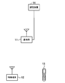
- FIG. 2 is a diagram illustrating an example of a wireless communication system according to the second embodiment.
- the wireless communication system includes a base station 11, a special terminal 12, a terminal 13, and an authentication device 14.
- the authentication device 14 is included in a core network (not shown).
- the base station 11 performs wireless communication with the special terminal 12 and the terminal 13.
- the base station 11 performs wireless communication by LTE (Long Term Term Evolution), for example.
- the base station 11 is connected to the authentication device 14 by wire, for example.
- the special terminal 12 is, for example, an MTC terminal such as a vending machine or a pacemaker.
- the vending machine for example, transmits information to that effect to the vendor via the base station 11 when the change has expired.
- the pacemaker transmits information to that effect to the vendor via the base station 11.
- the terminal 13 is a mobile phone, for example.
- the terminal 13 wirelessly communicates user data such as voice data, mail data, and moving image data with the base station 11.
- a terminal 13 such as a mobile phone performs wireless communication with the base station 11 several times a day, for example.
- the special terminal 12 such as a vending machine or a pacemaker transmits user data to the base station 11 only occasionally, such as when the change is cut or a failure occurs as described above. Therefore, the transmission timing of the user data of the special terminal 12 is more discrete than the terminal 13.
- the user data transmitted by radio from the special terminal 12 indicates information indicating that the change has been exhausted or information indicating that a failure has occurred. Accordingly, the user data communicated by the special terminal 12 is smaller in data size than the user data of the terminal 13.
- the authentication device 14 is, for example, an HSS (Home Subscriber Service). For example, the authentication device 14 determines whether the special terminal 12 and the terminal 13 are legitimate terminals based on terminal-specific information such as USIM (Universal Mobile Telecommunications System Subscriber Identity Module).
- HSS Home Subscriber Service
- USIM Universal Mobile Telecommunications System Subscriber Identity Module
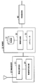
- FIG. 3 is a diagram illustrating an example of functional blocks of the base station.
- the base station 11 includes a wireless communication unit 20, a control unit 30, and a wired communication unit 40.
- the functions of the wireless communication unit 20 and the wired communication unit 40 are realized by a semiconductor device such as ASIC (Application Specific Specific Integrated Circuit).
- the function of the control unit 30 is realized by, for example, a CPU (Central Processing Unit) or DSP (Digital Signal Processor) executing a program stored in a storage device such as a memory.
- a CPU Central Processing Unit
- DSP Digital Signal Processor
- the wireless communication unit 20 includes a wireless transmission / reception unit 21 and a wireless signal measurement unit 22.
- the wireless transmission / reception unit 21 performs wireless communication with the special terminal 12 and the terminal 13.
- the radio signal measurement unit 22 measures information included in the radio signal.
- the wireless signal measurement unit 22 measures RS (Reference Signal) and SRS (Sounding Reference Signal).
- the control unit 30 includes a storage unit 31, an information processing unit 32, and a scheduler 33.
- the storage unit 31 is a storage device such as a memory, for example.
- the storage unit 31 stores, for example, an RNTI management table for managing RNTI (Radio Network Temporary Identifier) assigned to the special terminal 12 and the terminal 13.
- the RNTI is information for the information processing unit 32 to identify the special terminal 12 and the terminal 13.
- the information processing unit 32 accesses information stored in the storage unit 31 and performs information processing. In addition, the information processing unit 32 stores the processed information in the storage unit 31. Further, the information processing unit 32 exchanges information with the scheduler 33, the wireless communication unit 20, and the wired communication unit 40, and performs predetermined information processing.
- the scheduler 33 exchanges information with the information processing unit 32, the wireless communication unit 20, and the wired communication unit 40, and schedules the special terminal 12 and the terminal 13.
- the wired communication unit 40 performs wired communication with the core network.
- the wired communication unit 40 communicates with the authentication device 14 included in the core network.
- FIG. 4 is a diagram showing a data configuration example of the RNTI management table.
- the RNTI management table 31a has columns of RNTI, user, and special RNTI.
- an RNTI identifier assigned to the terminal 13 by the information processing unit 32 is stored.
- the identifier of the terminal 13 is stored in the user column on the right side of the RNTI column in FIG. Thereby, it can be seen that, for example, RNTI1 is assigned to the terminal 13 of the user C.
- an RNTI identifier assigned to the special terminal 12 by the information processing unit 32 is stored.
- the identifier of the special terminal 12 is stored in the user column on the right side of the special RNTI column in FIG. Thereby, for example, it is understood that the RNTI 11 is assigned to the special terminal 12 of the user A.
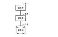
- FIG. 5 is a diagram illustrating an example of a functional block of the authentication device.
- the authentication device 14 includes a communication unit 51, an authentication unit 52, and a storage unit 53.
- the functions of the units illustrated in FIG. 5 are realized by, for example, the CPU executing a program stored in a storage device such as a memory.
- the terminal-specific information of the special terminal 12 and the terminal 13 is stored in advance.
- Information indicating that the terminal specific information belongs to the special terminal (hereinafter referred to as special terminal information) is further added to the terminal specific information of the special terminal 12 and stored in the storage unit 53.
- the terminal specific information is, for example, USIM.
- the communication unit 51 communicates with the base station 11.
- the authentication unit 52 performs authentication to determine whether the special terminal 12 and the terminal 13 that have requested authentication from the base station 11 are legitimate terminals manufactured by the vendor.
- the authentication unit 52 authenticates the special terminal 12 and the terminal 13 depending on whether or not the terminal specific information requested for authentication from the base station 11 is stored in the storage unit 53.
- the authentication unit 52 determines that the terminal that has made the authentication request is the special terminal 12.
- the authentication unit 52 transmits the authentication result to the base station 11 via the communication unit 51. For example, if the terminal specific information transmitted from the base station 11 is stored in the storage unit 53, the authentication unit 52 transmits an authentication result to the base station 11 indicating that the terminal that requested the authentication is a legitimate terminal. To do. If special terminal information is added to the terminal-specific information that has been authenticated with reference to the storage unit 53, the authentication unit 52 indicates that the terminal that requested the authentication is a legitimate terminal and is a special terminal. Is sent to the base station 11.
- FIG. 6 is a sequence diagram showing an operation of a connection request from the terminal to the base station.
- a RACH Random Access Channel
- One initial access is performed. Initial access is transmission / reception of a control signal for securing a radio bearer for transmitting / receiving user data between a base station and a terminal.
- Step S1 The terminal 13 transmits an RA (Random Access) preamble (RA Preamble) to the base station 11.
- RA Random Access
- RA Preamble RA Preamble
- Step S2 When the wireless transceiver 21 receives the RA preamble from the terminal 13, the information processing unit 32 of the base station 11 performs processing to transmit an RA response to the terminal 13.
- the RA response includes, for example, a temporary RNTI for the information processing unit 32 to identify the terminal 13, and UL (Up (Link) radio resource allocation information for the terminal 13 to transmit the next control signal to the base station 11. , Link adaptation information for determining a modulation scheme and a coding rate, and UL transmission power information are included.
- the UL radio resource allocation information included in the RA response is, for example, PUCCH (Physical-Uplink-Control-Channel) allocation information.
- UL radio resource allocation information is generated by the scheduler 33.
- the process of step S2 may be referred to as message 2.
- Step S3 The terminal 13 that has received the RA response from the base station 11 transmits an RRC (Radio Resource Control) connection request (RRC Connection Request) to the base station 11 using the temporary RNTI acquired by the RA response. For example, the terminal 13 transmits an RRC connection request to the base station 11 using the PUCCH allocated in step S2.
- the RRC connection request includes, for example, terminal specific information of the terminal 13.
- the process of step S3 may be referred to as message 3.
- Step S4 When the wireless transceiver 21 receives the RRC connection request from the terminal 13, the information processing unit 32 of the base station 11 transmits the terminal-specific information included in the RRC connection request to the authentication device 14, and the terminal 13 Authentication device 14 is requested to authenticate whether or not is a legitimate terminal (Initial RA).
- the information processing unit 32 receives information on whether or not the terminal 13 is a legitimate terminal from the authentication unit 52 of the authentication device 14 via the wired communication unit 40 (authentication result notification).
- authentication result notification indicating that it is a legitimate terminal.
- the information processing unit 32 since the terminal that requested authentication is the terminal 13, the authentication result does not include special terminal information. Therefore, the information processing unit 32 recognizes that the accessed terminal 13 is not a special terminal.
- Step S6 When the information processing unit 32 receives information from the authentication device 14 that the terminal 13 is a legitimate terminal, the information processing unit 32 transmits an RRC connection setup (RRC Connection Setup) to the terminal 13 to establish an RRC connection. To do.
- RRC connection setup RRC Connection Setup
- the RRC connection setup includes, for example, RNTI for identifying the terminal 13, UL radio resource allocation information, synchronization management information for synchronizing radio frames transmitted and received between the base station 11 and the terminal 13, and a link Includes adaptation information.
- RNTI included in the RRC connection setup is assigned by the information processing unit 32, and the information is stored in the RNTI management table 31a. Further, the synchronization management information and the link adaptation information are generated by the information processing unit 32.
- the UL radio resource allocation information is generated by the scheduler 33 and is, for example, PUCCH allocation information.
- the process of step S6 may be referred to as message 4.
- the base station 11 and the terminal 13 can transmit and receive user data (User Data) by establishing the RRC connection. For example, when transmitting user data to the base station 11, the terminal 13 transmits a control signal requesting user data transmission to the base station 11 using the UL radio resource (PUCCH) allocated in step S ⁇ b> 6.
- PUCCH UL radio resource
- Step S8 The information processing unit 32 of the base station 11 releases an RRC connection release (RRC Connection Release) to the terminal 13 when a predetermined time has elapsed from the last user data transmitted and received between the base station 11 and the terminal 13. ) To release the RRC connection with the terminal 13.
- the predetermined time is, for example, a time determined by an inactivity timer (Inactivity Timer).
- Inactivity Timer the period from when the RRC connection is established until it is released may be referred to as RRC connected (RRC Connected).
- the terminal 13 released from the RRC connection transmits / receives user data to / from the same base station 11 again, the terminal 13 performs a RACH procedure similar to the initial access shown in FIG. However, in the RACH procedure at this time, the authentication of the terminal 13 by the authentication unit 52 of the authentication device 14 is not performed.
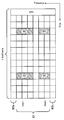
- FIG. 7 is a diagram for explaining UL radio resources.
- FIG. 7 shows a UL radio resource of one UL subframe (Sub Frame).
- the horizontal direction indicates time, and the vertical direction indicates frequency.
- FIG. 7 shows allocation of UL radio resources of users 1 and 2.
- a region 61 indicates a PUSCH (Physical-Uplink-Shared-Channel) region, and regions 62a and 62b indicate PUCCH regions.
- the PUSCH is shared and used by a plurality of terminals 13 based on assignment by the scheduler 33 of the base station 11, and is used for transmission of user data and higher layer control information, for example.
- PUCCH is used for transmission of a control signal, for example.
- PUCCH is arrange
- the scheduler 33 acquires the channel state of the terminal 13 in order to perform efficient UL radio resource allocation to the terminal 13. Therefore, the terminal 13 transmits SRS to the base station 11 using PUSCH separately from the RS for data demodulation. The scheduler 33 acquires the channel information of the terminal 13 based on the SRS from the terminal 13.
- the terminal 13 transmits a control signal to the base station 11 when in the RRC connected state.
- the control signal includes, for example, ACK / NACK information for the RS transmitted from the base station 11 to the terminal 13, a CQI (Channel Quality Indicator) report, a resource request for UL, and link adaptation information.
- CQI Channel Quality Indicator
- the terminal 13 transmits a control signal to the base station 11 using, for example, the PUCCH assigned in the message 4 (for example, step S6 in FIG. 6).
- the terminal 13 transmits a control signal to the base station 11 using the PUSCH when the PUSCH is assigned.
- the scheduler 33 assigns a UL radio resource to the terminal 13 when a resource request for UL is included in the control signal. Further, the scheduler 33 allocates a DL (Down Link) radio resource to the terminal 13 based on the CQI report included in the control signal received from the terminal 13.
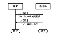
- FIG. 8 is a diagram for explaining UL scheduling.
- the terminal 13 wants to transmit data, it makes a UL resource request to the base station 11 using a control signal.
- the terminal 13 transmits a control signal to the base station 11 using, for example, the PUCCH assigned by the message 4.
- the scheduler 33 receives a UL resource request from the terminal 13 and allocates a UL radio resource to the terminal 13.
- the scheduler 33 allocates UL radio resources based on the SRS from the terminal 13.
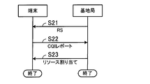
- FIG. 9 is a diagram for explaining DL scheduling.
- the information processing unit 32 transmits the RS to the terminal 13.
- the terminal 13 calculates a CQI based on the RS transmitted from the base station 11, and transmits a control signal including the CQI report to the base station 11.
- the terminal 13 transmits a control signal to the base station 11 using, for example, the PUCCH assigned by the message 4.
- FIG. 10 is a diagram for explaining PUCCH hopping.
- FIG. 10 shows UL radio resources.
- the horizontal direction indicates time, and the vertical direction indicates frequency.
- An area 66 indicates the PUSCH, and areas 66a and 66b indicate the PUCCH.
- the scheduler 33 assigns a PUCCH for the terminal 13 to transmit the message 3 to the terminal 13 in the message 2 as described above. In addition, in the message 4, the scheduler 33 allocates a PUCCH to the terminal 13 so that the terminal 13 can make a data transmission request using RRC connected. When allocating PUCCH to the terminal 13, the scheduler 33 divides one subframe in half and allocates PUCCH at both ends of the system band to different terminals 13.
- the scheduler 33 divides one subframe into halves and allocates them to users 1 and 2. At this time, the scheduler assigns user 1 to the PUCCH in one area 66a at a certain time, and assigns user 2 to the other area 66b. Then, in the remaining subframe, scheduler 33 assigns user 2 to the PUCCH in one region 66a and assigns user 1 to the PUCCH in the other region 66b.
- FIG. 11 is a sequence diagram showing an operation of a connection request from the special terminal to the base station.
- one of the RACH procedures is performed between a base station and a special terminal when the special terminal starts up in a cover area of the base station or when the special terminal moves to the cover area of the base station.
- Initial access is performed. Initial access is transmission / reception of a control signal for securing a radio bearer for transmitting / receiving user data between a base station and a special terminal.
- Step S31 The special terminal 12 transmits an RA preamble to the base station 11.
- the process of step S31 may be referred to as message 1.
- Step S32 When the wireless transceiver 21 receives the RA preamble from the special terminal 12, the information processing unit 32 of the base station 11 performs processing to transmit an RA response to the special terminal 12.
- the RA response includes, for example, a temporary special RNTI for the information processing unit 32 to identify the special terminal 12, UL radio resource allocation information for the special terminal 12 to transmit the next control signal to the base station 11, Link adaptation information for determining the modulation scheme and coding rate, and UL transmission power information are included.
- UL radio resource allocation information included in the RA response is generated by the scheduler 33, and is, for example, PUCCH allocation information.
- the temporary special RNTI, link adaptation information, and UL transmission power information are generated by the information processing unit 32.
- the process of step S32 may be referred to as message 2.
- Step S33 The special terminal 12 that has received the RA response from the base station 11 transmits an RRC connection request to the base station 11 using the temporary special RNTI included in the RA response.
- the special terminal 12 transmits an RRC connection request to the base station 11 using, for example, the PUCCH assigned in step S32.
- the RRC connection request includes, for example, terminal specific information of the special terminal 12.
- the processing in step S33 may be referred to as message 3.
- Step S34 When the wireless transceiver 21 receives the RRC connection request from the special terminal 12, the information processing unit 32 of the base station 11 transmits the terminal-specific information included in the RRC connection request to the authentication device 14, and the special information is transmitted to the authentication device 14.
- the authentication device 14 is requested to authenticate whether or not the terminal 12 is a legitimate terminal (Initial) RA).
- Step S35 The information processing unit 32 receives an authentication result indicating whether the special terminal 12 is a legitimate terminal from the authentication unit 52 of the authentication device 14 via the wired communication unit 40.
- the information processing unit 32 has received an authentication result notification indicating that it is a legitimate terminal.
- the authentication result includes special terminal information. Therefore, the information processing unit 32 recognizes that the accessed special terminal 12 is a special terminal.
- Step S36 Upon receiving an authentication result indicating that the special terminal 12 is a legitimate terminal and is a special terminal from the authentication device 14, the information processing section 32 transmits an RRC connection setup to the special terminal 12, and RRC Establish a connection.
- the RRC connection setup in the special terminal 12 includes, for example, a special RNTI for identifying the special terminal 12, and does not include UL radio resource allocation information, synchronization management information, and link adaptation information.
- the special RNTI included in the RRC connection setup is assigned by the information processing unit 32, and the information is stored in the RNTI management table 31a.
- the RRC connection setup includes RNTI, UL wireless resource allocation information, synchronization management information, and link adaptation. Contains information.
- the RRC connection setup includes the special RNTI, but does not include the UL radio resource allocation information, the synchronization management information, and the link adaptation information.
- step S36 may be referred to as message 4.
- the information processing unit 32 maintains the RRC connection and holds the context information of the special terminal 12 in a storage device such as a memory.
- the context information is, for example, terminal specific information of the special terminal 12 or service information of the special terminal 12. That is, unlike the case of the terminal 13, the information processing unit 32 does not release the RRC connection when the RRC connection with the special terminal 12 is established.
- FIG. 12 is a sequence diagram showing an operation when the special terminal transmits user data to the base station.
- UL radio resources for example, PUCCH
- PUCCH Physical Uplink Control Channel
- the terminal 13 transmits a control signal including a user data transmission request with the assigned UL radio resource to the base station 11. Transmit to station 11.
- the UL radio resource for the data transmission request is not allocated to the special terminal 12 as described in step S36 of FIG. That is, the UL radio resource for making a user data transmission request is not allocated to the special terminal 12.
- Step S41 The special terminal 12 performs the following RACH procedure when trying to transmit user data to the base station 11 after establishing an RRC connection with the base station 11.
- the special terminal 12 transmits an RA preamble to the base station 11.
- the process of step S41 may be referred to as message 1.
- Step S42 When the wireless transceiver 21 receives the RA preamble from the special terminal 12, the information processing unit 32 of the base station 11 performs processing to transmit an RA response to the special terminal 12.
- the RA response includes, for example, a temporary special RNTI for the information processing unit 32 to identify the special terminal 12, UL radio resource allocation information for the special terminal 12 to transmit the next control signal to the base station 11, Link adaptation information for determining the modulation scheme and coding rate, and UL transmission power information are included.
- UL radio resource allocation information included in the RA response is generated by the scheduler 33, and is, for example, PUCCH allocation information.
- the temporary special RNTI, link adaptation information, and UL transmission power information are generated by the information processing unit 32.
- the process of step S42 may be referred to as message 2.
- Step S43 The special terminal 12 transmits the special RNTI assigned at the time of establishing the RRC connection to the base station 11. That is, when the special terminal 12 requests the base station 11 to transmit user data, the special terminal 12 transmits the special RNTI assigned in step S36 of FIG.
- the process of step S43 may be referred to as message 3.
- the information processing unit 32 of the base station 11 refers to the RNTI management table 31a based on the special RNTI received from the special terminal 12.
- the information processing unit 32 determines that the special terminal 12 is an appropriate terminal without confirming the authentication with the authentication device 14. .
- the scheduler 33 allocates UL radio
- the information processing unit 32 does not generate synchronization management information and link adaptation information.
- the special terminal 12 transmits a special RNTI indicating that it is a special terminal to the base station 11 in the message 3 of the RACH procedure, and requests a UL radio resource. That is, when the special terminal 12 wants to transmit user data to the base station 11, the special terminal 12 requests the UL radio resource from the base station 11 without using the PUCCH. Thereby, the scheduler 33 can improve the utilization efficiency of UL radio
- 100 terminals can be connected to the base station 11. It is assumed that 90 terminals 13 are connected to the base station 11 and 10 special terminals 12 are connected to the base station 11.
- the scheduler when the UL radio resource for the data transmission request is also allocated to the special terminal 12, the scheduler performs scheduling for allocating 100 UL radio resources (resources for PUCCH) to the 100 terminals. Will do. However, since the scheduler 33 does not allocate a PUCCH for a data transmission request to the special terminal 12, it can allocate 100 PUCCHs to 90 terminals. That is, the scheduler 33 can improve the usage efficiency of UL radio resources.
- FIG. 13 is a flowchart showing the operation of the base station when there is an RRC connection request from the terminal.
- the information processing unit 32 receives an RRC connection request from a terminal (the special terminal 12 or the terminal 13). [Step S52] The information processing unit 32 transmits the terminal-specific information included in the RRC connection request to the authentication device 14, and makes an authentication request for the terminal that has made the RRC connection request.
- the information processing unit 32 receives the authentication result from the authentication device 14.
- the information processing section 32 determines whether the authentication result of the authentication device 14 is the regular terminal 13 or the regular special terminal 12. When the authentication result is the regular terminal 13, the information processing unit 32 proceeds to the process of step S55. If the authentication result is the authorized special terminal 12, the information processing unit 32 proceeds to the process of step S57.
- Step S55 The information processing unit 32 assigns an RNTI to the terminal 13.
- the information processing unit 32 stores the RNTI assigned to the terminal 13 in the RNTI management table 31a.
- the scheduler 33 and the information processing unit 32 allocate a normal bearer to the terminal 13.
- the scheduler 33 generates a UL radio resource for a user data transmission request
- the information processing unit 32 generates synchronization management information and link adaptation information.
- the normal bearer is a bearer other than the special bearer described below, and is, for example, a logical path for transferring audio information and moving image information.
- Step S57 The information processing section 32 assigns a special RNTI to the special terminal 12.
- the information processing unit 32 stores the special RNTI assigned to the special terminal 12 in the RNTI management table 31a.
- Step S58 The scheduler 33 and the information processing unit 32 allocate a special bearer to the special terminal 12. For example, the scheduler 33 does not generate a UL radio resource for a user data transmission request, and the information processing unit 32 does not generate synchronization management information and link adaptation information.
- the information processing unit 32 transmits an RRC connection setup to the terminal 13 or the special terminal 12, and establishes an RRC connection.
- the RRC connection setup to be transmitted to the terminal 13 includes, for example, RNTI for identifying the terminal 13, UL radio resource allocation information for user data transmission request, synchronization management information, and link adaptation information.
- the RRC connection setup to be transmitted to the special terminal 12 includes, for example, a special RNTI for identifying the terminal 13, and includes UL radio resource allocation information, synchronization management information, and link adaptation information for user data transmission requests. I can't.
- FIG. 14 is a flowchart showing the operation of the base station after transmitting the RRC connection setup.
- the flowchart in FIG. 14 shows, for example, the processing after step S6 in FIG. 6 and step S36 in FIG.
- the information processing unit 32 receives the last user data via the wireless transmission / reception unit 21.
- the information processing section 32 determines whether or not the terminal that transmitted the user data is the special terminal 12.
- the scheduler 33 assigns user data to the terminals (special terminal 12 and terminal 13). Therefore, the information processing unit 32 can determine whether the terminal that transmitted the user data is the special terminal 12 by receiving the allocation information from the scheduler 33.
- the information processing unit 32 ends the process when the terminal that transmitted the user data is the special terminal 12. Note that the RRC connection remains established. That is, the information processing unit 32 keeps establishing the RRC connection and holds the context information of the special terminal 12.
- the context information is, for example, terminal specific information or service information of the special terminal 12.
- step S63 The information processing section 32 starts an inactivity timer.
- Step S64 The information processing section 32 recognizes that the inactivity timer has expired.
- Step S65 The information processing section 32 releases the RRC connection. That is, the information processing unit 32 releases an RRC connection with the terminal 13 when the time of the inactivity timer has elapsed since the terminal 13 transmitted the last user data.
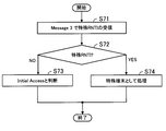
- FIG. 15 is a flowchart showing the determination operation of the special terminal of the base station.
- the information processing unit 32 receives the special RNTI from the special terminal 12 via the wireless transmission / reception unit 21 in the message 3 of the RACH procedure.
- the reception of the special RNTI of the message 3 is, for example, reception of the special RNTI in step S33 in FIG. 11 or reception of the special RNTI in step S43 in FIG.
- Step S72 The information processing section 32 determines whether or not the special RNTI received from the special terminal 12 is stored in the RNTI management table 31a. That is, the information processing unit 32 determines whether the special RNTI received from the special terminal 12 is a temporary special RNTI or a special RNTI (non-provisional special RNTI). In the case of the temporary special RNTI, the information processing section 32 proceeds to the process of step S73. In the case of the special RNTI, the information processing section 32 proceeds to step S74.
- Step S73 The information processing section 32 determines that the access of the special terminal 12 to the base station 11 is initial access.
- the information processing unit 32 makes an authentication request for the accessed special terminal 12 to the authentication device 14.
- Step S74 The information processing unit 32 determines that the accessed special terminal 12 is an appropriate terminal without making an authentication request to the authentication device 14.
- the information processing unit 32 determines that the access to the base station 11 by the special terminal 12 is a user data transmission request.
- the scheduler 33 allocates a UL radio resource (for example, PUSCH) for user data transmission to the special terminal 12 and notifies it by DL. Thereby, the special terminal 12 can transmit user data to the base station 11.
- PUSCH UL radio resource
- the core network includes, for example, a bearer management device that manages bearers.
- the bearer management device is, for example, an MME (Mobility Management Entity).
- the base station 11 is connected to the bearer management device, for example, by wire.
- FIG. 16 is a diagram showing an example of a bearer management table managed by the bearer management apparatus.
- FIG. 16 shows a bearer management table 71.
- the bearer management table 71 is formed in a storage device such as a memory of the bearer management device, for example.
- the bearer management table 71 stores bearers for transmitting and receiving user data.
- the bearer A indicates a bearer for the terminal 13 to transmit / receive voice user data
- the bearer X indicates the bearer for the terminal 13 to transmit / receive moving image user data.
- the special bearer is a bearer for the special terminal 12 to transmit and receive user data.
- a bearer allocation request is made to the bearer management apparatus. For example, when the bearer management apparatus receives a voice bearer request for the terminal 13 from the information processing unit 32, the bearer management apparatus allocates the bearer A to the base station 11. Further, for example, when receiving a bearer request for the special terminal 12 from the information processing unit 32, the bearer management device allocates a special bearer to the base station 11. The information processing unit 32 establishes a bearer assigned to the terminal 13 or the special terminal 12.
- the scheduler 33 allocates uplink radio resources for the special terminal 12 and the terminal 13 to make a data transmission request based on whether or not the terminal is the special terminal 12. Thereby, the scheduler 33 can improve the utilization efficiency of the uplink radio resource.
- the information processing unit 32 when the information processing unit 32 establishes the RRC connection with the special terminal 12, the information processing unit 32 does not release the RRC connection.
- the special terminal 12 can send a user data transmission request to the base station 11 simply by executing the RACH procedure, and does not need to make an RRC connection request each time user data is transmitted. That is, the communication processing load between the base station 11 and the special terminal 12 is reduced.
- the information processing unit 32 when the information processing unit 32 establishes an RRC connection with the special terminal 12, the information processing unit 32 does not release the RRC connection. Thereby, for example, the special terminal 12 can make a transmission request for user data to the base station 11 even when the number of terminals 13 corresponding to the limit amount of UL radio resources is connected to the base station 11. it can.
- the base station determines whether the accessed terminal is a special terminal based on the authentication result of the authentication device. recognize.
- the third embodiment when a special terminal accesses a base station, information indicating that the special terminal itself is a special terminal is notified to the base station.
- the wireless communication system according to the third embodiment is the same as that shown in FIG.
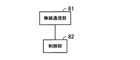
- FIG. 17 is a diagram illustrating an example of functional blocks of a special terminal according to the third embodiment.
- the special terminal 12 includes a wireless communication unit 81 and a control unit 82.
- the function of the wireless communication unit 81 is realized by a semiconductor device such as an ASIC, for example.
- the function of the control unit 82 is realized, for example, when the CPU executes a program stored in a storage device such as a memory.
- the wireless communication unit 81 performs wireless communication with the base station 11.
- the control unit 82 generates an RA preamble including information indicating that the special terminal 12 is a special terminal (hereinafter referred to as special terminal information).
- the control unit 82 transmits and receives information to and from the base station 11 via the wireless communication unit 81.
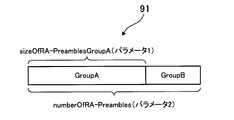
- FIG. 18 is a diagram showing a data configuration example of the RA preamble.
- FIG. 18 shows the RA preamble 91.
- SizeOfRA-PreamblesGroupA hereinafter referred to as parameter 1
- numberOfRA-Preambles hereinafter referred to as parameter 2)
- Parameter 1 indicates the size of the group A area
- parameter 2 indicates the overall size of the RA preamble 91.
- the control unit 82 generates an RA preamble that secures the group B area by setting parameter 1 ⁇ parameter 2.
- the control unit 82 stores the special terminal information in the group B area.
- the functional blocks of the base station 11 are the same as those in FIG. 3, but the information processing unit 32 recognizes that the accessed terminal is the special terminal 12 by the RA preamble transmitted from the special terminal 12. For example, as illustrated in FIG. 18, the information processing unit 32 recognizes that the accessed terminal is the special terminal 12 when the special terminal information is included in the group B of the RA preamble 91.
- the RNTI management table 31a does not have an area for storing a special RNTI and user information corresponding to the special RNTI.
- the information processing unit 32 assigns the same RNTI as that of the terminal 13 to the special terminal 12 and stores it in the RNTI management table 31a.
- FIG. 19 is a diagram illustrating a data configuration example of the RA response.
- the RA response 92 has areas 92a and 92b.
- the area 92a is a subheader area
- the area 92b is an information area indicated by the subheader.
- the subheader 1 in FIG. 19 indicates the position of information of MACCE (Media Access Control Control Element) 1.
- the information processing unit 32 adds an additional subheader to the area 92a of the RA response 92, for example, so that the additional information is stored in the area 92b.
- the information processing unit 32 stores information indicating that the special terminal 12 that has been accessed is processed as a special terminal in the additional information of the area 92b.
- the functional block of the authentication device 14 is the same as in FIG. 5, but no special terminal information is stored in the storage unit 53. That is, the storage unit 53 stores terminal-specific information in advance without distinguishing between the special terminal 12 and the terminal 13.
- the authentication unit 52 does not transmit an authentication result indicating that the authentication request is a special terminal to the base station 11 even if the terminal requested for authentication is a special terminal. That is, the authentication unit 52 does not have to determine that the terminal is a special terminal based on the terminal specific information, and the storage unit 53 does not have to store the special terminal information as described above.
- FIG. 20 is a sequence diagram showing an operation of a connection request from the special terminal to the base station.
- one of the RACH procedures is performed between a base station and a special terminal when the special terminal starts up in a cover area of the base station or when the special terminal moves to the cover area of the base station.
- Initial access is performed. Initial access is transmission / reception of a control signal for securing a radio bearer for transmitting / receiving user data between a base station and a special terminal.
- Step S81 The control unit 82 of the special terminal 12 generates an RA preamble including special terminal information, for example, as described with reference to FIG.
- the wireless communication unit 81 wirelessly transmits the RA preamble generated by the control unit 82 to the base station 11.
- the process of step S81 may be referred to as message 1.
- Step S82 When the wireless transceiver 21 receives the RA preamble from the special terminal 12, the information processing unit 32 of the base station 11 performs processing to transmit an RA response to the special terminal 12. The information processing unit 32 recognizes that the special terminal 12 is a special terminal by receiving the RA preamble including the special terminal information in step S81.
- the RA response includes, for example, a temporary RNTI, UL radio resource allocation information for the special terminal 12 to transmit the next control signal to the base station 11, link adaptation information for determining a modulation scheme and a coding rate, and UL transmission power information is included, and information indicating that the special terminal 12 described in FIG. 19 is processed as a special terminal is included.
- UL radio resource allocation information included in the RA response is generated by the scheduler 33, and is, for example, PUCCH allocation information.
- the processing in step S82 may be referred to as message 2.
- Step S83 The control unit 82 of the special terminal 12 that has received the RA response from the base station 11 transmits an RRC connection request to the base station 11 using the temporary RNTI included in the RA response. For example, the control unit 82 transmits an RRC connection request to the base station 11 using the PUCCH allocated in step S82.
- the RRC connection request includes, for example, terminal specific information of the special terminal 12.
- the process of step S83 may be referred to as message 3.
- Step S84 When the wireless transceiver 21 receives the RRC connection request from the special terminal 12, the information processing unit 32 of the base station 11 transmits the terminal-specific information included in the RRC connection request to the authentication device 14, and the special terminal Authentication device 14 is requested to authenticate whether 12 is a legitimate terminal.
- the information processing unit 32 receives an authentication result indicating whether or not the special terminal 12 is a legitimate terminal from the authentication unit 52 of the authentication device 14. Here, it is assumed that the information processing unit 32 has received an authentication result notification indicating that it is a legitimate terminal.
- Step S86 Upon receiving an authentication result indicating that the special terminal 12 is a legitimate terminal from the authentication device 14, the information processing unit 32 transmits an RRC connection setup to the special terminal 12 to establish an RRC connection.
- the RRC connection setup in the special terminal 12 includes, for example, RNTI for identifying the special terminal 12, and does not include UL radio resource allocation information, synchronization management information, and link adaptation information.
- the RNTI included in the RRC connection setup is assigned by the information processing unit 32, and the information is stored in the RNTI management table 31a.
- the RRC connection setup includes the special RNTI, but does not include UL radio resource allocation information, synchronization management information, and link adaptation information.
- the process of step S86 may be referred to as message 4.
- the information processing unit 32 maintains the RRC connection and holds the context information of the special terminal 12 in a storage device such as a memory. That is, unlike the case of the terminal 13, the information processing unit 32 does not release the RRC connection when the RRC connection with the special terminal 12 is established.
- FIG. 21 is a sequence diagram showing an operation when the special terminal transmits user data to the base station.
- UL radio resources for example, PUCCH
- PUCCH Physical Uplink Control Channel
- the special terminal 12 is not assigned a UL radio resource for making a user data transmission request. Therefore, the special terminal 12 performs the following RACH procedure when making a transmission request for user data to the base station 11 after establishing an RRC connection with the base station 11 by initial access.
- Step S91 The control unit 82 of the special terminal 12 generates an RA preamble including the special terminal information as described with reference to FIG.
- the wireless communication unit 81 wirelessly transmits the RA preamble generated by the control unit 82 to the base station 11.
- the process of step S91 may be referred to as message 1.
- Step S92 When the wireless transceiver 21 receives the RA preamble from the special terminal 12, the information processing unit 32 of the base station 11 performs processing to transmit an RA response to the special terminal 12. The information processing unit 32 recognizes that the special terminal 12 is a special terminal by receiving the RA preamble including the special terminal information in step S91.
- the RA response includes, for example, a temporary RNTI, UL radio resource allocation information for the special terminal 12 to transmit the next control signal to the base station 11, link adaptation information for determining a modulation scheme and a coding rate, and UL transmission power information is included, and information indicating that the special terminal 12 described in FIG. 19 is processed as a special terminal is included.
- the UL radio resource allocation information included in the RA response is, for example, PUCCH allocation information.
- UL radio resource allocation information is generated by the scheduler 33.
- the process of step S92 may be referred to as message 2.
- Step S93 The control unit 82 of the special terminal 12 that has received the RA response from the base station 11 uses the special RNTI assigned from the base station 11 in Step S86 instead of the temporary RNTI assigned in Step S92.
- Message 3 is transmitted to the base station 11.
- the special terminal 12 transmits the message 3 to the base station 11 using, for example, the PUCCH assigned in step S92.
- Step S94 Based on the special RNTI included in the received message 3, the information processing unit 32 of the base station 11 determines whether the accessing special terminal 12 has finished the authentication process (whether it is a legitimate terminal). . For example, when the special RNTI included in the received message 3 is held in the RNTI table, the information processing unit 32 determines that the special terminal 12 that has accessed is a legitimate terminal and sends an authentication request to the authentication device 14. Not performed.
- the scheduler 33 allocates a UL radio resource (for example, PUSCH) to the special terminal 12 and notifies it by DL.
- the information processing unit 32 does not generate synchronization management information and link adaptation information.
- the information processing unit 32 maintains the RRC connection even after the special terminal 12 finishes transmitting user data, and holds the context information of the special terminal 12.
- the special terminal 12 when the special terminal 12 wants to transmit user data, it transmits special terminal information indicating that it is a special terminal to the base station 11 in the RACH procedure message 1 and requests UL radio resources. That is, when the special terminal 12 wants to transmit user data to the base station 11, the special terminal 12 requests the UL radio resource from the base station 11 without using the PUCCH. Thereby, the scheduler 33 can improve the utilization efficiency of UL radio
- the authentication device 14 since the special terminal 12 transmits the special terminal information to the base station 11, the authentication device 14 does not have to determine that the terminal requested for authentication is the special terminal 12. That is, it is not necessary to change the authentication device 14.
- the functional blocks of the special terminal 12 are the same as those in FIG. 17 except that the control unit 82 generates a MAC PDU (PDU: Protocol Data Unit) of the RRC connection request including the special terminal information.
- PDU Protocol Data Unit
- FIG. 22 is a diagram for explaining notification of special terminal information by MAC PDU. As shown in FIG. 22, BSR (Buffer State Report) used by the special terminal is added to the MAC PDU as MACCE.
- BSR Buffer State Report
- control unit 82 notifies the base station 11 that it is a special terminal by using the Logical Channel ID Field values of the MACPDU. For example, when “11001” is stored in Logical Channel ID Field values of the MAC PDU, the control unit 82 indicates that the terminal that transmits the MAC PDU is a special terminal.
- FIG. 23 is a sequence diagram showing an operation of a connection request from the special terminal to the base station.
- one of the RACH procedures is performed between a base station and a special terminal when the special terminal starts up in a cover area of the base station or when the special terminal moves to the cover area of the base station.
- Initial access is performed. Initial access is transmission / reception of a control signal for securing a radio bearer for transmitting / receiving user data between a base station and a special terminal.
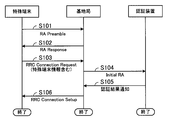
- Step S ⁇ b> 101 The special terminal 12 transmits an RA preamble to the base station 11.
- the process of step S101 may be referred to as message 1.
- Step S102 When the wireless transceiver 21 receives the RA preamble from the special terminal 12, the information processing unit 32 of the base station 11 performs processing to transmit an RA response to the special terminal 12.
- the RA response includes, for example, a temporary RNTI for the information processing unit 32 to identify the special terminal 12, UL radio resource allocation information for the special terminal 12 to transmit the next control signal to the base station 11, modulation Link adaptation information for determining the scheme and coding rate, and UL transmission power information are included.
- the UL radio resource allocation information included in the RA response is, for example, PUCCH allocation information.
- UL radio resource allocation information is generated by the scheduler 33.
- the process of step S102 may be referred to as message 2.
- Step S103 The control unit 82 of the special terminal 12 that has received the RA response from the base station 11 uses the provisional RNTI included in the RA response to the RRC including the terminal-specific information of the special terminal 12 with respect to the base station 11. Send a connection request.
- the control unit 82 stores “11001” in Logical Channel ID Field values of the MAC PDU, and includes special terminal information in the RRC connection request.
- the control unit 82 transmits an RRC connection request to the base station 11 using the PUCCH assigned in step S102.
- the processing in step S103 may be referred to as message 3.
- Step S104 When the wireless transmitting / receiving unit 21 receives the RRC connection request from the special terminal 12, the information processing unit 32 of the base station 11 transmits the terminal-specific information included in the RRC connection request to the authentication device 14, and the special information is received.
- the authentication device 14 is requested to authenticate whether or not the terminal 12 is a legitimate terminal.
- the information processing unit 32 receives an authentication result indicating whether or not the special terminal 12 is a legitimate terminal from the authentication unit 52 of the authentication device 14. Here, it is assumed that the information processing unit 32 has received an authentication result notification indicating that it is a legitimate terminal.
- Step S106 Upon receiving an authentication result indicating that the special terminal 12 is a legitimate terminal from the authentication device 14, the information processing unit 32 transmits an RRC connection setup to the special terminal 12 to establish an RRC connection.
- the RRC connection setup in the special terminal 12 includes, for example, RNTI for identifying the special terminal 12, and does not include UL radio resource allocation information, synchronization management information, and link adaptation information.
- the RNTI included in the RRC connection setup is assigned by the information processing unit 32, and the information is stored in the RNTI management table 31a.
- the RRC connection setup includes the special RNTI, but does not include UL radio resource allocation information, synchronization management information, and link adaptation information.
- the processing in step S106 may be referred to as message 4.
- the information processing unit 32 maintains the RRC connection and holds the context information of the special terminal 12 in a storage device such as a memory. That is, unlike the case of the terminal 13, the information processing unit 32 does not release the RRC connection when the RRC connection with the special terminal 12 is established.
- FIG. 24 is a sequence diagram showing an operation when the special terminal transmits user data to the base station.
- UL radio resources for example, PUCCH
- PUCCH Physical Uplink Control Channel
- the special terminal 12 performs the following RACH procedure when making a transmission request for user data to the base station 11 after establishing an RRC connection with the base station 11 by initial access.
- Step S111 The control unit 82 of the special terminal 12 generates an RA preamble.
- the wireless communication unit 81 wirelessly transmits the RA preamble generated by the control unit 82 to the base station 11.
- the process of step S111 may be referred to as message 1.
- Step S112 When the wireless transceiver 21 receives the RA preamble from the special terminal 12, the information processing unit 32 of the base station 11 performs processing to transmit an RA response to the special terminal 12.
- the RA response includes, for example, a temporary RNTI, UL radio resource allocation information for the special terminal 12 to transmit the next control signal to the base station 11, link adaptation information for determining a modulation scheme and a coding rate, and UL transmission power information is included.
- the UL radio resource allocation information included in the RA response is, for example, PUCCH allocation information.
- UL radio resource allocation information is generated by the scheduler 33.
- the processing in step S112 may be referred to as message 2.
- Step S113 The control unit 82 of the special terminal 12 that has received the RA response from the base station 11 uses the special RNTI assigned from the base station 11 in Step S106 instead of the temporary RNTI assigned in Step S112. Message 3 is transmitted to the base station 11.
- the special terminal 12 transmits the message 3 to the base station 11 using, for example, the PUCCH assigned in step S112.
- Step S114 Based on the special RNTI included in the received message 3, the information processing unit 32 of the base station 11 determines whether the accessing special terminal 12 has finished the authentication process (whether it is a legitimate terminal). . For example, when the special RNTI included in the received message 3 is held in the RNTI table, the information processing unit 32 determines that the special terminal 12 that has accessed is a legitimate terminal and sends an authentication request to the authentication device 14. Not performed.
- the scheduler 33 allocates a UL radio resource (for example, PUSCH) to the special terminal 12 and notifies it by DL.
- the information processing unit 32 does not generate synchronization management information and link adaptation information.
- the information processing unit 32 maintains the RRC connection even after the special terminal 12 finishes transmitting user data, and holds the context information of the special terminal 12.
- the special terminal 12 when the special terminal 12 wants to transmit user data, it transmits special terminal information indicating that it is a special terminal to the base station 11 in message 3 of the RACH procedure, and requests UL radio resources. That is, when the special terminal 12 wants to transmit user data to the base station 11, the special terminal 12 requests the UL radio resource from the base station 11 without using the PUCCH. Thereby, the scheduler 33 can improve the utilization efficiency of UL radio
- the authentication device 14 since the special terminal 12 transmits the special terminal information to the base station 11, the authentication device 14 does not have to determine that the terminal requested for authentication is the special terminal 12. That is, it is not necessary to change the authentication device 14.
- FIG. 25 is a diagram illustrating an example of a hardware block of the base station.
- the base station 100 includes a CPU 101, a memory 102, ASICs 103 and 104, and a bus 105.
- the entire base station 100 is controlled by the CPU 101.
- a memory 102 and ASICs 103 and 104 are connected to the CPU 101 via a bus 105.
- the CPU 101 may be a DSP.
- the base station may have a CPU 101 and a DSP.
- the memory 102 temporarily stores at least part of an OS (Operating System) program and application programs to be executed by the CPU 101.
- the memory 102 stores various data necessary for processing by the CPU 101. There may be a plurality of memories 102.
- the ASIC 103 performs wireless communication control
- the ASIC 104 performs wired communication control.
- the base station can realize the processing functions of the present embodiment.
Landscapes
- Engineering & Computer Science (AREA)
- Computer Security & Cryptography (AREA)
- Computer Networks & Wireless Communication (AREA)
- Signal Processing (AREA)
- Mobile Radio Communication Systems (AREA)
Abstract
アップリンク無線リソースの使用効率を向上する。 割り当て部(1a)は、端末(2,3)が第1の端末または第1の端末よりデータ送信を行うタイミングが離散した第2の端末であるか否かに基づいて、端末(2,3)が基地局(1)にデータ送信要求を行うためのアップリンク無線リソースを割り当てる。例えば、割り当て部(1a)は、第2の端末の端末(2)に対しては、データ送信要求のためのアップリンク無線リソースを割り当てない。割り当て部(1a)は、第1の端末の端末(3)に対しては、データ送信要求のためのアップリンク無線リソースを割り当てる。
Description
本件は、端末と無線通信を行う基地局、端末と無線通信を行う基地局と通信を行う認証装置、および基地局と無線通信を行う端末に関する。
基地局と無線通信を行う端末には、例えば、たまにしかユーザデータを送信しないMTC(Machine Type Communication)端末がある。例えば、自動販売機などのMTC端末は、釣銭が切れたときに、ベンダにその旨の情報を送信する。
なお、従来、基地局装置と移動局装置との同期通信に用いるパラメータを配置する無線フレーム上の領域に、移動局装置に対する上りリンク同期要求を表す情報を配置する移動局装置が提案されている(例えば、特許文献1参照)。
また、従来、移動局の状態や実際の送信手順のバリエーションに柔軟に対応可能であり、通信リソースの有効利用も可能な、EUTRA(Evolved Universal Terrestrial Radio Access)規格に準拠した、移動局と基地局との間の新規な上り接続処理を実現する接続処理方法が提案されている(例えば、特許文献2参照)。
しかし、たまにしかユーザデータを送信しないMTC端末に、例えば、携帯電話などの一般の携帯端末と同様にしてデータ送信要求のためのアップリンク無線リソースを割り当てると、アップリンク無線リソースの使用効率が低減するという問題点があった。
本件はこのような点に鑑みてなされたものであり、アップリンク無線リソースの使用効率を向上する基地局、認証装置、および端末を提供することを目的とする。
上記課題を解決するために、端末と無線通信を行う基地局が提供される。この基地局は、前記端末が第1の端末または前記第1の端末よりデータ送信を行うタイミングが離散した第2の端末であるか否かに基づいて、前記端末が当該基地局にデータ送信要求を行うためのアップリンク無線リソースを割り当てる割り当て部、を有する。
また、上記課題を解決するために、端末と無線通信を行う基地局と通信を行う認証装置が提供される。この認証装置は、前記端末が第1の端末または前記第1の端末よりデータ送信を行うタイミングが離散した第2の端末であるか否かの情報を記憶した記憶部と、前記基地局から前記端末の認証要求があった場合、前記記憶部を参照して、前記端末が前記第2の端末であるか否かを判断する判断部と、を有する。
また、上記課題を解決するために、基地局と無線通信を行う端末が提供される。この端末は、当該端末が第1の端末よりデータ送信を行うタイミングが離散した第2の端末である旨の端末情報を生成する生成部と、前記生成部によって生成された前記端末情報を前記基地局に無線送信する送信部と、を有する。
開示の装置によれば、アップリンク無線リソースの使用効率を向上することができる。
本発明の上記および他の目的、特徴および利点は本発明の例として好ましい実施の形態を表す添付の図面と関連した以下の説明により明らかになるであろう。
本発明の上記および他の目的、特徴および利点は本発明の例として好ましい実施の形態を表す添付の図面と関連した以下の説明により明らかになるであろう。
以下、実施の形態を、図面を参照して詳細に説明する。
[第1の実施の形態]
図1は、第1の実施の形態に係る基地局を示した図である。図1に示すように、基地局1は、割り当て部1aを有している。図1には、基地局1と無線通信を行う端末2,3も示してある。端末2は、端末3よりデータ送信を行うタイミングが離散した端末であり、例えば、MTC端末である。端末3は、例えば、携帯電話などの端末である。
[第1の実施の形態]
図1は、第1の実施の形態に係る基地局を示した図である。図1に示すように、基地局1は、割り当て部1aを有している。図1には、基地局1と無線通信を行う端末2,3も示してある。端末2は、端末3よりデータ送信を行うタイミングが離散した端末であり、例えば、MTC端末である。端末3は、例えば、携帯電話などの端末である。
割り当て部1aは、端末2,3が第1の端末または第1の端末よりデータ送信を行うタイミングが離散した第2の端末であるか否かに基づいて、端末2,3が基地局1に対してデータ送信要求を行うためのアップリンク無線リソースを割り当てる。
例えば、割り当て部1aは、MTC端末(第2の端末)の端末2に対しては、データ送信要求のためのアップリンク無線リソースを割り当てない。割り当て部1aは、携帯電話(第1の端末)の端末3に対しては、データ送信要求のためのアップリンク無線リソースを割り当てる。
このように、基地局1の割り当て部1aは、端末2,3が第1の端末または第1の端末よりデータ送信を行うタイミングが離散した第2の端末であるか否かに基づいて、端末2,3がデータ送信要求を行うためのアップリンク無線リソースを割り当てる。これにより、基地局1は、アップリンク無線リソースの使用効率を向上することができる。例えば、MTC端末の端末2に割り当てないデータ送信要求のためのアップリンク無線リソースを携帯電話の端末3に割り当てることが可能となる。
なお、端末3は、基地局1の割り当て部1aから割り当てられたアップリンク無線リソースを用いて基地局1にデータ送信要求を行うことができる。
一方、端末2は、以下で説明するが、例えば、基地局1に対してイニシャルアクセスしたとき、基地局1によって正規の端末と認識されると、第2の端末であることを示す識別子が割り当てられる。端末2は、基地局1に対してデータ送信要求をしたい場合、基地局1から割り当てられた識別子を、例えば、ランダムアクセスチャネルプロシージャにて送信する。基地局1は、ランダムアクセスチャネルプロシージャにて識別子を受信することにより、端末2からデータ送信要求があったと認識し、端末2に対してデータ送信のためのアップリンク無線リソースを割り当てる。これにより、端末2は、データを基地局1に無線送信することができる。
一方、端末2は、以下で説明するが、例えば、基地局1に対してイニシャルアクセスしたとき、基地局1によって正規の端末と認識されると、第2の端末であることを示す識別子が割り当てられる。端末2は、基地局1に対してデータ送信要求をしたい場合、基地局1から割り当てられた識別子を、例えば、ランダムアクセスチャネルプロシージャにて送信する。基地局1は、ランダムアクセスチャネルプロシージャにて識別子を受信することにより、端末2からデータ送信要求があったと認識し、端末2に対してデータ送信のためのアップリンク無線リソースを割り当てる。これにより、端末2は、データを基地局1に無線送信することができる。
[第2の実施の形態]
次に、第2の実施の形態を、図面を参照して詳細に説明する。
図2は、第2の実施の形態に係る無線通信システムの一例を示した図である。図2に示すように、無線通信システムは、基地局11、特殊端末12、端末13、および認証装置14を有している。認証装置14は、例えば、図示していないコアネットワークに含まれている。
次に、第2の実施の形態を、図面を参照して詳細に説明する。
図2は、第2の実施の形態に係る無線通信システムの一例を示した図である。図2に示すように、無線通信システムは、基地局11、特殊端末12、端末13、および認証装置14を有している。認証装置14は、例えば、図示していないコアネットワークに含まれている。
基地局11は、特殊端末12および端末13と無線通信を行う。基地局11は、例えば、LTE(Long Term Evolution)による無線通信を行う。基地局11は、例えば、有線によって認証装置14と接続されている。
特殊端末12は、例えば、自動販売機やペースメーカなどのMTC端末である。自動販売機は、例えば、釣銭が切れたとき、基地局11を介して、ベンダにその旨の情報を送信する。ペースメーカは、例えば、機器に障害が発生したき、基地局11を介して、ベンダにその旨の情報を送信する。
端末13は、例えば、携帯電話である。端末13は、音声データやメールデータ、動画データなどのユーザデータを基地局11と無線通信する。
携帯電話などの端末13は、例えば、1日に数回、基地局11と無線通信を行う。これに対し、自動販売機やペースメーカなどの特殊端末12は、前記したように釣銭が切れたときや障害が発生したときなど、たまにしかユーザデータを基地局11に送信しない。従って、特殊端末12のユーザデータの送信タイミングは、端末13より離散している。
携帯電話などの端末13は、例えば、1日に数回、基地局11と無線通信を行う。これに対し、自動販売機やペースメーカなどの特殊端末12は、前記したように釣銭が切れたときや障害が発生したときなど、たまにしかユーザデータを基地局11に送信しない。従って、特殊端末12のユーザデータの送信タイミングは、端末13より離散している。
また、特殊端末12の無線送信するユーザデータは、釣銭が切れた旨の情報や障害が発生した旨の情報を示すものである。従って、特殊端末12の通信するユーザデータは、端末13のユーザデータに対し、データサイズが小さい。
認証装置14は、例えば、HSS(Home Subscriber Service)である。認証装置14は、例えば、USIM(Universal Mobile Telecommunications System Subscriber Identity Module)などの端末固有情報によって、特殊端末12および端末13が正規の端末であるか否か判断する。
図3は、基地局の機能ブロックの一例を示した図である。図3に示すように、基地局11は、無線通信部20、制御部30、および有線通信部40を有している。無線通信部20および有線通信部40は、例えば、ASIC(Application Specific Integrated Circuit)などの半導体装置によって、その機能が実現される。また、制御部30は、例えば、CPU(Central Processing Unit)やDSP(Digital Signal Processor)がメモリなどの記憶装置に記憶されているプログラムを実行することによって、その機能が実現される。
無線通信部20は、無線送受信部21および無線信号測定部22を有している。無線送受信部21は、特殊端末12および端末13と無線通信を行う。無線信号測定部22は、無線信号に含まれる情報を測定する。例えば、無線信号測定部22は、RS(Reference Signal)やSRS(Sounding Reference Signal)を測定する。
制御部30は、記憶部31、情報処理部32、およびスケジューラ33を有している。記憶部31は、例えば、メモリなどの記憶装置である。記憶部31は、例えば、特殊端末12および端末13に割り当てたRNTI(Radio Network Temporary Identifier)を管理するRNTI管理テーブルを記憶している。RNTIは、情報処理部32が特殊端末12および端末13を識別するための情報である。
情報処理部32は、記憶部31に記憶されている情報にアクセスし、情報処理を行う。また、情報処理部32は、処理した情報を記憶部31に記憶する。また、情報処理部32は、スケジューラ33、無線通信部20、および有線通信部40と情報のやり取りを行い、所定の情報処理を行う。
スケジューラ33は、情報処理部32、無線通信部20、および有線通信部40と情報のやり取りを行い、特殊端末12および端末13のスケジューリングを行う。
有線通信部40は、コアネットワークと有線による通信を行う。例えば、有線通信部40は、コアネットワークに含まれている認証装置14と通信を行う。
有線通信部40は、コアネットワークと有線による通信を行う。例えば、有線通信部40は、コアネットワークに含まれている認証装置14と通信を行う。
図4は、RNTI管理テーブルのデータ構成例を示した図である。図4に示すRNTI管理テーブル31aは、記憶部31に形成される。RNTI管理テーブル31aは、RNTI、ユーザ、および特殊RNTIの欄を有している。
RNTIの欄には、情報処理部32が端末13に割り当てたRNTIの識別子が記憶される。図4のRNTIの欄の右隣のユーザの欄には、端末13の識別子が記憶される。これにより、例えば、ユーザCの端末13には、RNTI1が割り当てられたことが分かる。
特殊RNTIの欄には、情報処理部32が特殊端末12に割り当てたRNTIの識別子が記憶される。図4の特殊RNTIの欄の右隣のユーザの欄には、特殊端末12の識別子が記憶される。これにより、例えば、ユーザAの特殊端末12には、RNTI11が割り当てられたことが分かる。
図5は、認証装置の機能ブロックの一例を示した図である。図5に示すように、認証装置14は、通信部51、認証部52、および記憶部53を有している。図5に示す各部は、例えば、CPUがメモリなどの記憶装置に記憶されているプログラムを実行することによって、その機能が実現される。
記憶部53には、特殊端末12および端末13の端末固有情報が予め記憶されている。特殊端末12の端末固有情報には、その端末固有情報が特殊端末のものである旨の情報(以下、特殊端末情報と呼ぶ)がさらに付加されて、記憶部53に記憶されている。端末固有情報は、例えば、USIMである。
通信部51は、基地局11と通信を行う。認証部52は、例えば、基地局11から認証要求のあった特殊端末12および端末13が、ベンダの製造した正規の端末であるか否か認証を行う。例えば、認証部52は、基地局11から認証要求のあった端末固有情報が記憶部53に記憶されているか否かによって、特殊端末12および端末13の認証を行う。認証部52は、記憶部53を参照して認証を行った端末固有情報に特殊端末情報が付加されている場合、認証要求のあった端末は、特殊端末12であると判断する。
認証部52は、通信部51を介して、認証結果を基地局11に送信する。例えば、認証部52は、基地局11から送信された端末固有情報が記憶部53に記憶されていれば、認証要求のあった端末は正規の端末である旨の認証結果を基地局11に送信する。また、認証部52は、記憶部53を参照して認証を行った端末固有情報に特殊端末情報が付加されていれば、認証要求のあった端末は正規の端末であり、特殊端末である旨の認証結果を基地局11に送信する。
基地局11と特殊端末12の無線通信動作および基地局11と端末13の無線通信動作について説明する。まず、基地局11と端末13の無線通信動作について説明する。
図6は、端末から基地局への接続要求の動作を示したシーケンス図である。例えば、LTEでは、端末がある基地局のカバーエリアで起動したときや、端末がある基地局のカバーエリアに移動してきたとき、基地局と端末との間で、RACH(Random Access Channel)プロシージャの1つであるイニシャルアクセス(Initial Access)が行われる。イニシャルアクセスは、基地局と端末との間でユーザデータの送受信を行うための無線ベアラを確保するためのコントロールシグナルの送受信である。
図6は、端末から基地局への接続要求の動作を示したシーケンス図である。例えば、LTEでは、端末がある基地局のカバーエリアで起動したときや、端末がある基地局のカバーエリアに移動してきたとき、基地局と端末との間で、RACH(Random Access Channel)プロシージャの1つであるイニシャルアクセス(Initial Access)が行われる。イニシャルアクセスは、基地局と端末との間でユーザデータの送受信を行うための無線ベアラを確保するためのコントロールシグナルの送受信である。
[ステップS1]端末13は、基地局11に対して、RA(Random Access)プリアンブル(RA Preamble)を送信する。以下では、このステップS1の処理をメッセージ1と呼ぶことがある。
[ステップS2]基地局11の情報処理部32は、無線送受信部21が端末13からのRAプリアンブルを受信すると、端末13に対してRAレスポンス(RA Response)を送信するよう処理する。
RAレスポンスには、例えば、情報処理部32が端末13を識別するための仮のRNTI、端末13が次のコントロールシグナルを基地局11に対して送信するためのUL(Up Link)無線リソース割り当て情報、変調方式や符号化率を決定するリンクアダプテーション(Link Adaptation)情報、およびUL送信電力情報が含まれる。
RAレスポンスに含まれるUL無線リソース割り当て情報は、例えば、PUCCH(Physical Uplink Control Channel)の割り当て情報である。UL無線リソース割り当て情報は、スケジューラ33によって生成される。以下では、このステップS2の処理をメッセージ2と呼ぶことがある。
[ステップS3]基地局11からRAレスポンスを受信した端末13は、RAレスポンスで取得した仮のRNTIを用いて基地局11に、RRC(Radio Resource Control)コネクションリクエスト(RRC Connection Request)を送信する。端末13は、例えば、ステップS2で割り当てられたPUCCHを用いて、RRCコネクションリクエストを基地局11へ送信する。RRCコネクションリクエストには、例えば、端末13の端末固有情報が含まれている。以下では、このステップS3の処理をメッセージ3と呼ぶことがある。
[ステップS4]基地局11の情報処理部32は、無線送受信部21が端末13からのRRCコネクションリクエストを受信すると、RRCコネクションリクエストに含まれる端末固有情報を認証装置14に送信して、端末13が正規の端末であるかどうかの認証を認証装置14に要求する(Initial RA)。
[ステップS5]情報処理部32は、有線通信部40を介して、認証装置14の認証部52から、端末13が正規の端末であるか否かの情報を受信する(認証結果通知)。ここでは、情報処理部32は、正規の端末である旨の認証結果通知を受信したとする。また、認証要求した端末は、端末13であるので、認証結果には、特殊端末情報は含まれていない。従って、情報処理部32は、アクセスしてきた端末13は、特殊端末でないと認識する。
[ステップS6]情報処理部32は、認証装置14から端末13が正規の端末であるとの情報を受信すると、端末13に対してRRCコネクションセットアップ(RRC Connection Setup)を送信し、RRCコネクションを確立する。
RRCコネクションセットアップには、例えば、端末13を識別するためのRNTI、UL無線リソース割り当て情報、基地局11と端末13との間で送受信される無線フレームの同期をとるための同期管理情報、およびリンクアダプテーション情報が含まれる。
RRCコネクションセットアップに含まれるRNTIは、情報処理部32によって割り当てられ、その情報は、RNTI管理テーブル31aに記憶される。また、同期管理情報およびリンクアダプテーション情報は、情報処理部32によって生成される。また、UL無線リソース割り当て情報は、スケジューラ33によって生成され、例えば、PUCCHの割り当て情報である。以下では、このステップS6の処理をメッセージ4と呼ぶことがある。
[ステップS7]基地局11と端末13は、RRCコネクションの確立によって、ユーザデータ(User Data)の送受信が可能となる。例えば、端末13は、基地局11にユーザデータを送信する場合、ステップS6で割り当てられたUL無線リソース(PUCCH)を用いて、ユーザデータ送信を要求するコントロールシグナルを基地局11に送信する。
[ステップS8]基地局11の情報処理部32は、基地局11と端末13との間で送受信された最後のユーザデータから所定時間が経過すると、端末13に対してRRCコネクションリリース(RRC Connection Release)を送信し、端末13との間のRRCコネクションをリリースする。所定時間は、例えば、インアクティビティタイマ(Inactivity Timer)で定まる時間である。以下では、RRCコネクションが確立されてからリリースされるまでを、RRCコネクティッド(RRC Connected)と呼ぶことがある。
RRCコネクションからリリースされた端末13は、再度同一の基地局11とユーザデータの送受信を行う場合、基地局11との間で、図6に示すイニシャルアクセスと同様のRACHプロシージャを行う。ただし、このときのRACHプロシージャでは、認証装置14の認証部52による端末13の認証は行われない。
図7は、UL無線リソースを説明する図である。図7には、ULの1サブフレーム(Sub Frame)のUL無線リソースが示してある。横方向は時間を示し、縦方向は周波数を示している。
図7には、ユーザ(User)1,2のUL無線リソースの割り当てが示してある。領域61は、PUSCH(Physical Uplink Shared Channel)の領域を示し、領域62a,62bは、PUCCHの領域を示している。PUSCHは、例えば、基地局11のスケジューラ33による割り当てに基づいて、複数の端末13で共有して用いられ、ユーザデータや上位レイヤの制御情報の伝送に用いられる。PUCCHは、例えば、コントロールシグナルの伝送に用いられる。PUCCHは、領域62a,62bに示すように、システム帯域の両端に配置される。
スケジューラ33は、端末13に対して効率的なUL無線リソース割り当てを行うため、端末13のチャネル状態を取得する。そのため、端末13は、データ復調のためのRSとは別に、PUSCHでSRSを基地局11に送信する。スケジューラ33は、端末13からのSRSに基づいて、端末13のチャネル情報を取得する。
また、端末13は、RRCコネクティッドにあるとき、基地局11に対して、コントロールシグナルを送信する。コントロールシグナルには、例えば、基地局11から端末13へ送信されたRSに対するACK/NACK情報、CQI(Channel Quality Indicator)レポート、ULのためのリソース要求、およびリンクアダプテーション情報が含まれている。
端末13は、例えば、メッセージ4(例えば、図6のステップS6)で割り当てられたPUCCHを用いて、コントロールシグナルを基地局11へ送信する。端末13は、コントロールシグナルを、PUSCHが割り当てられているときはPUSCHを用いて基地局11へ送信する。
スケジューラ33は、コントロールシグナルにULのためのリソース要求が含まれている場合、端末13にUL無線リソースを割り当てる。また、スケジューラ33は、端末13から受信したコントロールシグナルに含まれるCQIレポートに基づいて、DL(Down Link)無線リソースを端末13に割り当てる。
図8は、ULスケジューリングを説明する図である。
[ステップS11]端末13は、データ送信をしたい場合、基地局11に対し、コントロールシグナルでULリソース要求を行う。端末13は、例えば、メッセージ4で割り当てられたPUCCHを用いて、コントロールシグナルを基地局11に送信する。
[ステップS11]端末13は、データ送信をしたい場合、基地局11に対し、コントロールシグナルでULリソース要求を行う。端末13は、例えば、メッセージ4で割り当てられたPUCCHを用いて、コントロールシグナルを基地局11に送信する。
[ステップS12]スケジューラ33は、端末13からのULリソース要求を受けて、端末13に対し、UL無線リソースを割り当てる。スケジューラ33は、端末13からのSRSに基づいて、UL無線リソースを割り当てる。
図9は、DLスケジューリングを説明する図である。
[ステップS21]情報処理部32は、RSを端末13に送信する。
[ステップS22]端末13は、基地局11から送信されたRSに基づいてCQIを算出し、CQIレポートを含むコントロールシグナルを基地局11に送信する。端末13は、例えば、メッセージ4で割り当てられたPUCCHを用いて、コントロールシグナルを基地局11に送信する。
[ステップS21]情報処理部32は、RSを端末13に送信する。
[ステップS22]端末13は、基地局11から送信されたRSに基づいてCQIを算出し、CQIレポートを含むコントロールシグナルを基地局11に送信する。端末13は、例えば、メッセージ4で割り当てられたPUCCHを用いて、コントロールシグナルを基地局11に送信する。
[ステップS23]スケジューラ33は、受信されたCQIレポートに基づいて、端末13に対し、DL無線リソースを割り当てる。
図10は、PUCCHのホッピングを説明する図である。図10には、UL無線リソースが示してある。横方向は時間を示し、縦方向は周波数を示している。領域66は、PUSCHを示し、領域66a,66bは、PUCCHを示している。
図10は、PUCCHのホッピングを説明する図である。図10には、UL無線リソースが示してある。横方向は時間を示し、縦方向は周波数を示している。領域66は、PUSCHを示し、領域66a,66bは、PUCCHを示している。
スケジューラ33は、上記したようにメッセージ2において、端末13がメッセージ3を送信するためのPUCCHを端末13に割り当てる。また、スケジューラ33は、メッセージ4において、端末13がRRCコネクティッドにてデータ送信要求ができるようにPUCCHを端末13に割り当てる。スケジューラ33は、端末13にPUCCHを割り当てるとき、1サブフレームを半分に分割し、異なる端末13にシステム帯域の両端のPUCCHを割り当てるようにする。
例えば、スケジューラ33は、図10に示すように、1サブフレームを半分に分割し、ユーザ1,2に割り当てる。このとき、スケジューラは、ある時刻における一方の領域66aのPUCCHにユーザ1を割り当て、他方の領域66bにユーザ2を割り当てる。そして、スケジューラ33は、残りのサブフレームにおいて、一方の領域66aのPUCCHにユーザ2を割り当て、他方の領域66bのPUCCHにユーザ1を割り当てる。
次に、基地局11と特殊端末12の無線通信動作について説明する。
図11は、特殊端末から基地局への接続要求の動作を示したシーケンス図である。例えば、LTEでは、特殊端末がある基地局のカバーエリアで起動したときや、特殊端末がある基地局のカバーエリアに移動してきたとき、基地局と特殊端末との間で、RACHプロシージャの1つであるイニシャルアクセスが行われる。イニシャルアクセスは、基地局と特殊端末との間でユーザデータの送受信を行うための無線ベアラを確保するためのコントロールシグナルの送受信である。
図11は、特殊端末から基地局への接続要求の動作を示したシーケンス図である。例えば、LTEでは、特殊端末がある基地局のカバーエリアで起動したときや、特殊端末がある基地局のカバーエリアに移動してきたとき、基地局と特殊端末との間で、RACHプロシージャの1つであるイニシャルアクセスが行われる。イニシャルアクセスは、基地局と特殊端末との間でユーザデータの送受信を行うための無線ベアラを確保するためのコントロールシグナルの送受信である。
[ステップS31]特殊端末12は、基地局11に対して、RAプリアンブルを送信する。以下では、このステップS31の処理をメッセージ1と呼ぶことがある。
[ステップS32]基地局11の情報処理部32は、無線送受信部21が特殊端末12からのRAプリアンブルを受信すると、特殊端末12に対してRAレスポンスを送信するよう処理する。
[ステップS32]基地局11の情報処理部32は、無線送受信部21が特殊端末12からのRAプリアンブルを受信すると、特殊端末12に対してRAレスポンスを送信するよう処理する。
RAレスポンスには、例えば、情報処理部32が特殊端末12を識別するための仮の特殊RNTI、特殊端末12が次のコントロールシグナルを基地局11に対して送信するためのUL無線リソース割り当て情報、変調方式や符号化率を決定するリンクアダプテーション情報、およびUL送信電力情報が含まれる。
RAレスポンスに含まれるUL無線リソース割り当て情報は、スケジューラ33によって生成され、例えば、PUCCHの割り当て情報である。仮の特殊RNTI、リンクアダプテーション情報、およびUL送信電力情報は、情報処理部32によって生成される。以下では、このステップS32の処理をメッセージ2と呼ぶことがある。
[ステップS33]基地局11からRAレスポンスを受信した特殊端末12は、RAレスポンスに含まれる仮の特殊RNTIを用いて、基地局11に対しRRCコネクションリクエストを送信する。特殊端末12は、例えば、ステップS32で割り当てられたPUCCHを用いて、RRCコネクションリクエストを基地局11へ送信する。RRCコネクションリクエストには、例えば、特殊端末12の端末固有情報が含まれている。以下では、このステップS33の処理をメッセージ3と呼ぶことがある。
[ステップS34]基地局11の情報処理部32は、無線送受信部21が特殊端末12からのRRCコネクションリクエストを受信すると、RRCコネクションリクエストに含まれる端末固有情報を認証装置14に送信して、特殊端末12が正規の端末であるか否かの認証を認証装置14に要求する(Initial RA)。
[ステップS35]情報処理部32は、有線通信部40を介して、認証装置14の認証部52から特殊端末12が正規の端末であるか否かの認証結果を受信する。ここでは、情報処理部32は、正規の端末である旨の認証結果通知を受信したとする。また、認証要求した端末は、特殊端末12であるので、認証結果には、特殊端末情報が含まれている。従って、情報処理部32は、アクセスしてきた特殊端末12は、特殊端末であると認識する。
[ステップS36]情報処理部32は、認証装置14から特殊端末12が正規の端末であり、特殊端末であるとの認証結果を受信すると、特殊端末12に対してRRCコネクションセットアップを送信し、RRCコネクションを確立する。
特殊端末12におけるRRCコネクションセットアップには、例えば、特殊端末12を識別するための特殊RNTIが含まれ、UL無線リソース割り当て情報、同期管理情報、およびリンクアダプテーション情報が含まれていない。RRCコネクションセットアップに含まれる特殊RNTIは、情報処理部32によって割り当てられ、その情報は、RNTI管理テーブル31aに記憶される。
すなわち、イニシャルアクセスにおいて、無線通信しようとする端末が端末13の場合、図6のステップS6で説明したように、RRCコネクションセットアップには、RNTI、UL無線リソース割り当て情報、同期管理情報、およびリンクアダプテーション情報が含まれる。これに対し、無線通信しようとする端末が特殊端末12の場合、RRCコネクションセットアップには、特殊RNTIが含まれるが、UL無線リソース割り当て情報、同期管理情報、およびリンクアダプテーション情報が含まれない。
つまり、情報処理部32は、アクセスしてきた端末が特殊端末12の場合、特殊端末12を同期管理およびリンクアダプテーションの対象外とし、スケジューラ33は、特殊端末12に対し、データ送信要求のためのUL無線リソース(例えば、PUCCH)を割り当てない。以下では、このステップS36の処理をメッセージ4と呼ぶことがある。
なお、情報処理部32は、特殊端末12とRRCコネクションを確立すると、そのRRCコネクションを維持し、特殊端末12のコンテキスト情報を、例えば、メモリなどの記憶装置に保持する。コンテキスト情報は、例えば、特殊端末12の端末固有情報や特殊端末12のサービス情報である。すなわち、情報処理部32は、端末13の場合と異なり、特殊端末12とのRRCコネクションを確立すると、そのRRCコネクションをリリースしない。
図12は、特殊端末が基地局にユーザデータを送信する場合の動作を示したシーケンス図である。上記したように、端末13には、ユーザデータの送信要求を基地局11に対して行うためのUL無線リソース(例えば、PUCCH)が割り当てられる。例えば、端末13は、図6のステップS6でUL無線リソースが割り当てられ、基地局11に対してユーザデータを送信したい場合、その割り当てられたUL無線リソースでユーザデータ送信要求を含むコントロールシグナルを基地局11に送信する。
これに対し、特殊端末12には、図11のステップS36で説明したように、データ送信要求のためのUL無線リソースが割り当てられない。すなわち、特殊端末12には、ユーザデータの送信要求を行うためのUL無線リソースが割り当てられない。
そこで、特殊端末12は、基地局11とRRCコネクションを確立した後、基地局11にユーザデータを送信しようとする場合、以下のRACHプロシージャを行う。
[ステップS41]特殊端末12は、基地局11に対して、RAプリアンブルを送信する。以下では、このステップS41の処理をメッセージ1と呼ぶことがある。
[ステップS41]特殊端末12は、基地局11に対して、RAプリアンブルを送信する。以下では、このステップS41の処理をメッセージ1と呼ぶことがある。
[ステップS42]基地局11の情報処理部32は、無線送受信部21が特殊端末12からのRAプリアンブルを受信すると、特殊端末12に対してRAレスポンスを送信するよう処理する。
RAレスポンスには、例えば、情報処理部32が特殊端末12を識別するための仮の特殊RNTI、特殊端末12が次のコントロールシグナルを基地局11に対して送信するためのUL無線リソース割り当て情報、変調方式や符号化率を決定するリンクアダプテーション情報、およびUL送信電力情報が含まれる。
RAレスポンスに含まれるUL無線リソース割り当て情報は、スケジューラ33によって生成され、例えば、PUCCHの割り当て情報である。仮の特殊RNTI、リンクアダプテーション情報、およびUL送信電力情報は、情報処理部32によって生成される。以下では、このステップS42の処理をメッセージ2と呼ぶことがある。
[ステップS43]特殊端末12は、RRCコネクションの確立の際に割り当てられた特殊RNTIを基地局11に送信する。すなわち、特殊端末12は、基地局11に対してユーザデータの送信を要求する場合、図11のステップS36で割り当てられた特殊RNTIを基地局11に送信する。以下では、このステップS43の処理をメッセージ3と呼ぶことがある。
[ステップS44]基地局11の情報処理部32は、特殊端末12から受信した特殊RNTIに基づいて、RNTI管理テーブル31aを参照する。情報処理部32は、特殊端末12から受信した特殊RNTIがRNTI管理テーブル31aに記憶されている場合、認証装置14に対して認証確認をすることなく、その特殊端末12を適切な端末と判断する。そして、スケジューラ33は、特殊端末12にUL無線リソース(例えば、PUSCH)を割り当て、DLにて通知する。なお、情報処理部32は、同期管理情報およびリンクアダプテーション情報を生成しない。
すなわち、特殊端末12は、RACHプロシージャのメッセージ3にて、特殊端末であることを示す特殊RNTIを基地局11に送信してUL無線リソースの要求を行う。つまり、特殊端末12は、ユーザデータを基地局11に送信したい場合、PUCCHを使用することなく、基地局11にUL無線リソースを要求する。これにより、スケジューラ33は、UL無線リソースの使用効率を向上することができる。
例えば、基地局11には、100機の端末の接続が可能であるとする。そして、端末13が90機、基地局11に接続され、特殊端末12が10機、基地局11に接続されているとする。
ここで、特殊端末12にもデータ送信要求のためのUL無線リソースを割り当てるとした場合、スケジューラは、100機分のUL無線リソース(PUCCHのためのリソース)を100機の端末に配分するスケジューリングを行うことになる。しかし、スケジューラ33は、特殊端末12にデータ送信要求のためのPUCCHを割り当てないので、100機分のPUCCHを90機の端末に配分することができる。すなわち、スケジューラ33は、UL無線リソースの使用効率を向上することができる。
なお、情報処理部32は、特殊端末12がユーザデータを送信し終えた後もRRCコネクションを維持し続け、特殊端末12のコンテキスト情報を保持する。
図13は、端末からRRCコネクションリクエストがあったときの基地局の動作を示したフローチャートである。
図13は、端末からRRCコネクションリクエストがあったときの基地局の動作を示したフローチャートである。
[ステップS51]情報処理部32は、端末(特殊端末12または端末13)からRRCコネクションリクエストを受信する。
[ステップS52]情報処理部32は、認証装置14に対してRRCコネクションリクエストに含まれている端末固有情報を送信し、RRCコネクションリクエストしてきた端末の認証要求を行う。
[ステップS52]情報処理部32は、認証装置14に対してRRCコネクションリクエストに含まれている端末固有情報を送信し、RRCコネクションリクエストしてきた端末の認証要求を行う。
[ステップS53]情報処理部32は、認証装置14から認証結果を受信する。
[ステップS54]情報処理部32は、認証装置14の認証結果が正規の端末13であるかまたは正規の特殊端末12であるか否か判断する。情報処理部32は、認証結果が正規の端末13である場合、ステップS55の処理へ進む。情報処理部32は、認証結果が正規の特殊端末12である場合、ステップS57の処理へ進む。
[ステップS54]情報処理部32は、認証装置14の認証結果が正規の端末13であるかまたは正規の特殊端末12であるか否か判断する。情報処理部32は、認証結果が正規の端末13である場合、ステップS55の処理へ進む。情報処理部32は、認証結果が正規の特殊端末12である場合、ステップS57の処理へ進む。
[ステップS55]情報処理部32は、端末13に対してRNTIを割り当てる。情報処理部32は、端末13に割り当てたRNTIをRNTI管理テーブル31aに記憶する。
[ステップS56]スケジューラ33および情報処理部32は、端末13に通常のベアラを割り当てる。例えば、スケジューラ33は、ユーザデータ送信要求のためのUL無線リソースを生成し、情報処理部32は、同期管理情報およびリンクアダプテーション情報を生成する。通常のベアラとは、以下で述べる特殊ベアラ以外のベアラであり、例えば、音声情報や動画情報を転送するための論理的なパスである。
[ステップS57]情報処理部32は、特殊端末12に対して特殊RNTIを割り当てる。情報処理部32は、特殊端末12に割り当てた特殊RNTIをRNTI管理テーブル31aに記憶する。
[ステップS58]スケジューラ33および情報処理部32は、特殊端末12に特殊ベアラを割り当てる。例えば、スケジューラ33は、ユーザデータ送信要求のためのUL無線リソースを生成せず、情報処理部32は、同期管理情報およびリンクアダプテーション情報を生成しない。
[ステップS59]情報処理部32は、端末13または特殊端末12に対してRRCコネクションセットアップを送信し、RRCコネクションを確立する。
端末13に送信するRRCコネクションセットアップには、例えば、端末13を識別するためのRNTI、ユーザデータ送信要求のためのUL無線リソース割り当て情報、同期管理情報、およびリンクアダプテーション情報が含まれる。特殊端末12に送信するRRCコネクションセットアップには、例えば、端末13を識別するための特殊RNTIが含まれ、ユーザデータ送信要求のためのUL無線リソース割り当て情報、同期管理情報、およびリンクアダプテーション情報は含まれない。
端末13に送信するRRCコネクションセットアップには、例えば、端末13を識別するためのRNTI、ユーザデータ送信要求のためのUL無線リソース割り当て情報、同期管理情報、およびリンクアダプテーション情報が含まれる。特殊端末12に送信するRRCコネクションセットアップには、例えば、端末13を識別するための特殊RNTIが含まれ、ユーザデータ送信要求のためのUL無線リソース割り当て情報、同期管理情報、およびリンクアダプテーション情報は含まれない。
図14は、RRCコネクションセットアップ送信後の基地局の動作を示したフローチャートである。図14のフローチャートは、例えば、図6のステップS6および図11のステップS36以降の処理を示している。
[ステップS61]情報処理部32は、無線送受信部21を介して最後のユーザデータを受信する。
[ステップS62]情報処理部32は、ユーザデータを送信した端末が特殊端末12であるか否か判断する。なお、スケジューラ33が端末(特殊端末12および端末13)へのユーザデータの割り当てを行う。従って、情報処理部32は、スケジューラ33から割り当て情報を受け取ることにより、ユーザデータを送信した端末が特殊端末12であるか判断できる。
[ステップS62]情報処理部32は、ユーザデータを送信した端末が特殊端末12であるか否か判断する。なお、スケジューラ33が端末(特殊端末12および端末13)へのユーザデータの割り当てを行う。従って、情報処理部32は、スケジューラ33から割り当て情報を受け取ることにより、ユーザデータを送信した端末が特殊端末12であるか判断できる。
情報処理部32は、ユーザデータを送信した端末が特殊端末12であった場合、処理を終了する。なお、RRCコネクションは、確立されたままである。すなわち、情報処理部32は、RRCコネクションを確立し続け、特殊端末12のコンテキスト情報を保持する。コンテキスト情報は、例えば、特殊端末12の端末固有情報やサービス情報である。
情報処理部32は、ユーザデータを送信した端末が端末13であった場合、ステップS63へ進む。
[ステップS63]情報処理部32は、インアクティブタイマを開始する。
[ステップS63]情報処理部32は、インアクティブタイマを開始する。
[ステップS64]情報処理部32は、インアクティブタイマの満了を認識する。
[ステップS65]情報処理部32は、RRCコネクションをリリースする。すなわち、情報処理部32は、端末13が最後のユーザデータを送信してから、インアクティブタイマの時間を経過すると、端末13との間のRRCコネクションをリリースする。
[ステップS65]情報処理部32は、RRCコネクションをリリースする。すなわち、情報処理部32は、端末13が最後のユーザデータを送信してから、インアクティブタイマの時間を経過すると、端末13との間のRRCコネクションをリリースする。
図15は、基地局の特殊端末の判断動作を示したフローチャートである。
[ステップS71]情報処理部32は、RACHプロシージャのメッセージ3にて、無線送受信部21を介して特殊端末12から特殊RNTIを受信する。メッセージ3の特殊RNTIの受信は、例えば、図11のステップS33での特殊RNTIの受信または図12のステップS43での特殊RNTIの受信である。
[ステップS71]情報処理部32は、RACHプロシージャのメッセージ3にて、無線送受信部21を介して特殊端末12から特殊RNTIを受信する。メッセージ3の特殊RNTIの受信は、例えば、図11のステップS33での特殊RNTIの受信または図12のステップS43での特殊RNTIの受信である。
[ステップS72]情報処理部32は、特殊端末12から受信した特殊RNTIがRNTI管理テーブル31aに記憶されているか否か判断する。すなわち、情報処理部32は、特殊端末12から受信した特殊RNTIが仮の特殊RNTIであるか特殊RNTI(仮でない特殊RNTI)であるか判断する。情報処理部32は、仮の特殊RNTIの場合、ステップS73の処理へ進む。情報処理部32は、特殊RNTIの場合、ステップS74へ進む。
[ステップS73]情報処理部32は、特殊端末12の基地局11へのアクセスがイニシャルアクセスと判断する。情報処理部32は、認証装置14に対して、アクセスしてきた特殊端末12の認証要求を行う。
[ステップS74]情報処理部32は、認証装置14に対して認証要求をすることなく、アクセスしてきた特殊端末12を適切な端末と判断する。また、情報処理部32は、特殊端末12の基地局11へのアクセスがユーザデータの送信要求であると判断する。スケジューラ33は、特殊端末12にユーザデータ送信のためのUL無線リソース(例えば、PUSCH)を割り当て、DLにて通知する。これにより、特殊端末12は、基地局11に対してユーザデータを送信することができる。
ベアラ管理について説明する。コアネットワークには、例えば、ベアラを管理するベアラ管理装置が含まれている。ベアラ管理装置は、例えば、MME(Mobility Management Entity)である。基地局11は、例えば、有線によってベアラ管理装置と接続されている。
図16は、ベアラ管理装置で管理されるベアラ管理テーブルの一例を示した図である。図16には、ベアラ管理テーブル71が示してある。ベアラ管理テーブル71は、例えば、ベアラ管理装置のメモリなどの記憶装置に形成される。
ベアラ管理テーブル71には、ユーザデータの送受信をするためのベアラが記憶されている。例えば、ベアラAは、端末13が音声用のユーザデータを送受信するためのベアラを示し、ベアラXは、端末13が動画用のユーザデータを送受信するためのベアラを示している。特殊ベアラは、特殊端末12がユーザデータを送受信するためのベアラを示している。
基地局11の情報処理部32は、例えば、図6のステップS5の結果通知または図11のステップS35の結果通知で端末13または特殊端末12が適切な端末であるとの認証結果を受けると、ベアラ管理装置に対し、ベアラの割り当て要求を行う。ベアラ管理装置は、例えば、情報処理部32から、端末13の音声用のベアラ要求を受けた場合、基地局11に対し、ベアラAを割り当てる。また、ベアラ管理装置は、例えば、情報処理部32から、特殊端末12のベアラ要求を受けた場合、基地局11に対し、特殊ベアラを割り当てる。情報処理部32は、端末13または特殊端末12との間で割り当てられたベアラを張る。
このように、スケジューラ33は、端末が特殊端末12であるか否かに基づいて、特殊端末12および端末13がデータ送信要求を行うためのアップリンク無線リソースを割り当てる。これにより、スケジューラ33は、アップリンク無線リソースの使用効率を向上することができる。
また、情報処理部32は、特殊端末12とRRCコネクションを確立すると、RRCコネクションをリリースしない。これにより、特殊端末12は、RACHプロシージャを実行するだけで基地局11に対しユーザデータの送信要求を行うことが可能となり、ユーザデータを送信するたびに、RRCコネクションリクエストをしなくて済む。すなわち、基地局11と特殊端末12との間の通信処理負担が軽減される。
さらに、情報処理部32は、特殊端末12とRRCコネクションを確立すると、RRCコネクションをリリースしない。これにより、特殊端末12は、例えば、基地局11にUL無線リソースの限界量に相当する数の端末13が接続されている状況でも、基地局11に対し、ユーザデータの送信要求を行うことができる。
[第3の実施の形態]
次に、第3の実施の形態を、図面を参照して詳細に説明する。第2の実施の形態では、例えば、図6のステップS5および図11のステップS35で説明したように、基地局は、認証装置の認証結果によって、アクセスしてきた端末が特殊端末であるか否か認識する。第3の実施の形態では、特殊端末が基地局にアクセスする際、特殊端末自身が特殊端末である旨の情報を基地局に通知する。なお、第3の実施の形態の無線通信システムは、図2と同様であり、その説明は省略する。
次に、第3の実施の形態を、図面を参照して詳細に説明する。第2の実施の形態では、例えば、図6のステップS5および図11のステップS35で説明したように、基地局は、認証装置の認証結果によって、アクセスしてきた端末が特殊端末であるか否か認識する。第3の実施の形態では、特殊端末が基地局にアクセスする際、特殊端末自身が特殊端末である旨の情報を基地局に通知する。なお、第3の実施の形態の無線通信システムは、図2と同様であり、その説明は省略する。
図17は、第3の実施の形態に係る特殊端末の機能ブロックの一例を示した図である。図17に示すように、特殊端末12は、無線通信部81および制御部82を有している。無線通信部81は、例えば、ASICなどの半導体装置によって、その機能が実現される。制御部82は、例えば、CPUがメモリなどの記憶装置に記憶されているプログラムを実行することによって、その機能が実現される。
無線通信部81は、基地局11と無線通信を行う。制御部82は、当該特殊端末12が特殊端末である旨の情報(以下、特殊端末情報と呼ぶ)を含むRAプリアンブルを生成する。また、制御部82は、無線通信部81を介して基地局11と情報の送受信を行う。
図18は、RAプリアンブルのデータ構成例を示した図である。図18には、RAプリアンブル91が示してある。図18に示すsizeOfRA-PreamblesGroupA(以下、パラメータ1と呼ぶ)とnumberOfRA-Preambles(以下、パラメータ2と呼ぶ)は、RAプリアンブル91の領域を設定するパラメータである。パラメータ1は、グループAの領域の大きさを示し、パラメータ2は、RAプリアンブル91の全体の大きさを示す。
制御部82は、パラメータ1<パラメータ2と設定することでグループBの領域を確保したRAプリアンブルを生成する。制御部82は、グループBの領域に特殊端末情報を格納する。
基地局11の機能ブロックは、図3と同様であるが、情報処理部32は、特殊端末12から送信されるRAプリアンブルによって、アクセスしてきた端末が特殊端末12であることを認識する。例えば、情報処理部32は、図18に示すように、RAプリアンブル91のグループBに特殊端末情報が含まれている場合、アクセスしてきた端末が特殊端末12であると認識する。
また、RNTI管理テーブル31aは、例えば、図4に示したように、特殊RNTIとその特殊RNTIに対応するユーザの情報を記憶する領域を有さない。情報処理部32は、特殊端末12に対して端末13と同様のRNTIを割り当て、RNTI管理テーブル31aに記憶する。
また、情報処理部32は、RAレスポンスを特殊端末12に返すとき、特殊端末12に対して、特殊端末として処理することを示す情報を含める。
図19は、RAレスポンスのデータ構成例を示した図である。図19に示すように、RAレスポンス92は、領域92a,92bを有している。領域92aは、サブヘッダ(Subheader)の領域であり、領域92bは、サブヘッダが示す情報の領域である。例えば、図19のサブヘッダ1は、MACCE(Media Access Control Control Element)1の情報の位置を示している。
図19は、RAレスポンスのデータ構成例を示した図である。図19に示すように、RAレスポンス92は、領域92a,92bを有している。領域92aは、サブヘッダ(Subheader)の領域であり、領域92bは、サブヘッダが示す情報の領域である。例えば、図19のサブヘッダ1は、MACCE(Media Access Control Control Element)1の情報の位置を示している。
情報処理部32は、例えば、RAレスポンス92の領域92aに、追加サブヘッダを追加し、領域92bに追加情報が格納されるようにする。情報処理部32は、領域92bの追加情報に、アクセスしてきた特殊端末12に対して特殊端末として処理することを示す情報を格納する。
認証装置14の機能ブロックは、図5と同様であるが、記憶部53には、特殊端末情報が記憶されていない。すなわち、記憶部53には、特殊端末12および端末13を区別せず、端末固有情報が予め記憶されている。
また、認証部52は、認証要求された端末が特殊端末であっても、特殊端末である旨の認証結果を基地局11に送信しない。すなわち、認証部52は、端末固有情報によって、端末が特殊端末であることを判断しなくてもよく、記憶部53は、上記したように、特殊端末情報を記憶しなくてよい。
図20は、特殊端末から基地局への接続要求の動作を示したシーケンス図である。例えば、LTEでは、特殊端末がある基地局のカバーエリアで起動したときや、特殊端末がある基地局のカバーエリアに移動してきたとき、基地局と特殊端末との間で、RACHプロシージャの1つであるイニシャルアクセスが行われる。イニシャルアクセスは、基地局と特殊端末との間でユーザデータの送受信を行うための無線ベアラを確保するためのコントロールシグナルの送受信である。
[ステップS81]特殊端末12の制御部82は、例えば、図18で説明したように、特殊端末情報を含むRAプリアンブルを生成する。無線通信部81は、制御部82で生成されたRAプリアンブルを基地局11に無線送信する。以下では、このステップS81の処理をメッセージ1と呼ぶことがある。
[ステップS82]基地局11の情報処理部32は、無線送受信部21が特殊端末12からのRAプリアンブルを受信すると、特殊端末12に対してRAレスポンスを送信するよう処理する。情報処理部32は、ステップS81の特殊端末情報を含むRAプリアンブルを受信することによって、特殊端末12が特殊端末であることを認識する。
RAレスポンスには、例えば、仮のRNTI、特殊端末12が次のコントロールシグナルを基地局11に対して送信するためのUL無線リソース割り当て情報、変調方式や符号化率を決定するリンクアダプテーション情報、およびUL送信電力情報が含まれるとともに、図19で説明した特殊端末12を特殊端末として処理する旨の情報が含まれる。
RAレスポンスに含まれるUL無線リソース割り当て情報は、スケジューラ33によって生成され、例えば、PUCCHの割り当て情報である。以下では、このステップS82の処理をメッセージ2と呼ぶことがある。
[ステップS83]基地局11からRAレスポンスを受信した特殊端末12の制御部82は、RAレスポンスに含まれる仮のRNTIを用いて、基地局11に対しRRCコネクションリクエストを送信する。制御部82は、例えば、ステップS82で割り当てられたPUCCHを用いて、RRCコネクションリクエストを基地局11へ送信する。RRCコネクションリクエストには、例えば、特殊端末12の端末固有情報が含まれている。以下では、このステップS83の処理をメッセージ3と呼ぶことがある。
[ステップS84]基地局11の情報処理部32は、無線送受信部21が特殊端末12からのRRCコネクションリクエストを受信すると、RRCコネクションリクエストに含まれる端末固有情報を認証装置14に送信し、特殊端末12が正規の端末であるか否かの認証を認証装置14に要求する。
[ステップS85]情報処理部32は、認証装置14の認証部52から特殊端末12が正規の端末であるか否かの認証結果を受信する。ここでは、情報処理部32は、正規の端末である旨の認証結果通知を受信したとする。
[ステップS86]情報処理部32は、認証装置14から特殊端末12が正規の端末であるとの認証結果を受信すると、特殊端末12に対してRRCコネクションセットアップを送信し、RRCコネクションを確立する。
特殊端末12におけるRRCコネクションセットアップには、例えば、特殊端末12を識別するためのRNTIが含まれ、UL無線リソース割り当て情報、同期管理情報、およびリンクアダプテーション情報が含まれていない。RRCコネクションセットアップに含まれるRNTIは、情報処理部32によって割り当てられ、その情報は、RNTI管理テーブル31aに記憶される。
すなわち、無線通信しようとする端末が特殊端末12の場合、RRCコネクションセットアップには、特殊RNTIが含まれるが、UL無線リソース割り当て情報、同期管理情報、およびリンクアダプテーション情報が含まれない。以下では、このステップS86の処理をメッセージ4と呼ぶことがある。
なお、情報処理部32は、特殊端末12とRRCコネクションを確立すると、そのRRCコネクションを維持し、特殊端末12のコンテキスト情報を、例えば、メモリなどの記憶装置に保持する。すなわち、情報処理部32は、端末13の場合と異なり、特殊端末12とのRRCコネクションを確立すると、そのRRCコネクションをリリースしない。
図21は、特殊端末が基地局にユーザデータを送信する場合の動作を示したシーケンス図である。端末13には、第2の実施の形態で説明したように、基地局11に対してユーザデータの送信要求を行うためのUL無線リソース(例えば、PUCCH)が割り当てられる。
これに対し、特殊端末12には、図20のステップS86で説明したように、ユーザデータの送信要求を行うためのUL無線リソースが割り当てられない。
そこで、特殊端末12は、イニシャルアクセスにて基地局11とRRCコネクションを確立した後、基地局11に対してユーザデータの送信要求をする場合、以下のRACHプロシージャを行う。
そこで、特殊端末12は、イニシャルアクセスにて基地局11とRRCコネクションを確立した後、基地局11に対してユーザデータの送信要求をする場合、以下のRACHプロシージャを行う。
[ステップS91]特殊端末12の制御部82は、例えば、図18で説明したように、特殊端末情報を含むRAプリアンブルを生成する。無線通信部81は、制御部82で生成されたRAプリアンブルを基地局11に無線送信する。以下では、このステップS91の処理をメッセージ1と呼ぶことがある。
[ステップS92]基地局11の情報処理部32は、無線送受信部21が特殊端末12からのRAプリアンブルを受信すると、特殊端末12に対してRAレスポンスを送信するよう処理する。情報処理部32は、ステップS91の特殊端末情報を含むRAプリアンブルを受信することによって、特殊端末12が特殊端末であることを認識する。
RAレスポンスには、例えば、仮のRNTI、特殊端末12が次のコントロールシグナルを基地局11に対して送信するためのUL無線リソース割り当て情報、変調方式や符号化率を決定するリンクアダプテーション情報、およびUL送信電力情報が含まれるとともに、図19で説明した特殊端末12を特殊端末として処理する旨の情報が含まれる。
RAレスポンスに含まれるUL無線リソース割り当て情報は、例えば、PUCCHの割り当て情報である。UL無線リソース割り当て情報は、スケジューラ33によって生成される。以下では、このステップS92の処理をメッセージ2と呼ぶことがある。
[ステップS93]基地局11からRAレスポンスを受信した特殊端末12の制御部82は、ステップS92で割り当てられた仮のRNTIではなく、ステップS86で基地局11から割り当てられた特殊RNTIを用いて、基地局11に対しメッセージ3を送信する。特殊端末12は、例えば、ステップS92で割り当てられたPUCCHを用いて、メッセージ3を基地局11へ送信する。
[ステップS94]基地局11の情報処理部32は、受信したメッセージ3に含まれる特殊RNTIに基づいて、アクセスしてきた特殊端末12が認証処理を終えているか(正規の端末であるか)判断する。例えば、情報処理部32は、受信したメッセージ3に含まれる特殊RNTIがRNTIテーブルに保持されている場合、アクセスしてきた特殊端末12は正規の端末であると判断し、認証装置14に認証要求を行わない。
そして、スケジューラ33は、特殊端末12にUL無線リソース(例えば、PUSCH)を割り当て、DLにて通知する。なお、情報処理部32は、同期管理情報およびリンクアダプテーション情報を生成しない。また、情報処理部32は、特殊端末12がユーザデータを送信し終えた後もRRCコネクションを維持し続け、特殊端末12のコンテキスト情報を保持する。
すなわち、特殊端末12は、ユーザデータを送信したい場合、RACHプロシージャのメッセージ1にて、特殊端末であることを示す特殊端末情報を基地局11に送信し、UL無線リソースの要求を行う。つまり、特殊端末12は、ユーザデータを基地局11に送信したい場合、PUCCHを使用することなく、基地局11にUL無線リソースを要求する。これにより、スケジューラ33は、UL無線リソースの使用効率を向上することができる。
また、特殊端末12が特殊端末情報を基地局11に送信するので、認証装置14は、認証要求された端末が特殊端末12であることの判断をしなくて済む。すなわち、認証装置14を変更しなくて済む。
[第4の実施の形態]
次に、第4の実施の形態を、図面を参照して詳細に説明する。第3の実施の形態では、RACHプロシージャのメッセージ1にて、特殊端末であることを示す特殊端末情報を基地局11に送信した。第4の実施の形態では、RACHプロシージャのメッセージ3にて、特殊端末であることを示す特殊端末情報を基地局11に送信する。
次に、第4の実施の形態を、図面を参照して詳細に説明する。第3の実施の形態では、RACHプロシージャのメッセージ1にて、特殊端末であることを示す特殊端末情報を基地局11に送信した。第4の実施の形態では、RACHプロシージャのメッセージ3にて、特殊端末であることを示す特殊端末情報を基地局11に送信する。
特殊端末12の機能ブロックは、図17と同様であるが、制御部82は、特殊端末情報を含むRRCコネクションリクエストのMACPDU(PDU:Protocol Data Unit)を生成するところが異なる。
図22は、MACPDUによる特殊端末情報の通知を説明する図である。図22に示すように、特殊端末が使用するBSR(Buffer State Report)をMACCEとしてMACPDUに追加する。
例えば、制御部82は、MACPDUのLogical Channel ID Field valuesで基地局11に対し、特殊端末であることを通知する。例えば、制御部82は、MACPDUのLogical Channel ID Field valuesに“11001”を格納した場合、当該MACPDUを送信する端末は、特殊端末であることを示す。
図23は、特殊端末から基地局への接続要求の動作を示したシーケンス図である。例えば、LTEでは、特殊端末がある基地局のカバーエリアで起動したときや、特殊端末がある基地局のカバーエリアに移動してきたとき、基地局と特殊端末との間で、RACHプロシージャの1つであるイニシャルアクセスが行われる。イニシャルアクセスは、基地局と特殊端末との間でユーザデータの送受信を行うための無線ベアラを確保するためのコントロールシグナルの送受信である。
[ステップS101]特殊端末12は、基地局11に対して、RAプリアンブルを送信する。以下では、このステップS101の処理をメッセージ1と呼ぶことがある。
[ステップS102]基地局11の情報処理部32は、無線送受信部21が特殊端末12からのRAプリアンブルを受信すると、特殊端末12に対してRAレスポンスを送信するよう処理する。
[ステップS102]基地局11の情報処理部32は、無線送受信部21が特殊端末12からのRAプリアンブルを受信すると、特殊端末12に対してRAレスポンスを送信するよう処理する。
RAレスポンスには、例えば、情報処理部32が特殊端末12を識別するための仮のRNTI、特殊端末12が次のコントロールシグナルを基地局11に対して送信するためのUL無線リソース割り当て情報、変調方式や符号化率を決定するリンクアダプテーション情報、およびUL送信電力情報が含まれる。
RAレスポンスに含まれるUL無線リソース割り当て情報は、例えば、PUCCHの割り当て情報である。UL無線リソース割り当て情報は、スケジューラ33によって生成される。以下では、このステップS102の処理をメッセージ2と呼ぶことがある。
[ステップS103]基地局11からRAレスポンスを受信した特殊端末12の制御部82は、RAレスポンスに含まれる仮のRNTIを用いて、基地局11に対し、特殊端末12の端末固有情報を含むRRCコネクションリクエストを送信する。このとき、制御部82は、例えば、図22で説明したように、MACPDUのLogical Channel ID Field valuesに“11001”を格納し、RRCコネクションリクエストに特殊端末情報を含める。制御部82は、例えば、ステップS102で割り当てられたPUCCHを用いて、RRCコネクションリクエストを基地局11へ送信する。以下では、このステップS103の処理をメッセージ3と呼ぶことがある。
[ステップS104]基地局11の情報処理部32は、無線送受信部21が特殊端末12からのRRCコネクションリクエストを受信すると、RRCコネクションリクエストに含まれる端末固有情報を認証装置14に送信して、特殊端末12が正規の端末であるか否かの認証を認証装置14に要求する。
[ステップS105]情報処理部32は、認証装置14の認証部52から特殊端末12が正規の端末であるか否の認証結果を受信する。ここでは、情報処理部32は、正規の端末である旨の認証結果通知を受信したとする。
[ステップS106]情報処理部32は、認証装置14から特殊端末12が正規の端末であるとの認証結果を受信すると、特殊端末12に対してRRCコネクションセットアップを送信し、RRCコネクションを確立する。
特殊端末12におけるRRCコネクションセットアップには、例えば、特殊端末12を識別するためのRNTIが含まれ、UL無線リソース割り当て情報、同期管理情報、およびリンクアダプテーション情報が含まれていない。RRCコネクションセットアップに含まれるRNTIは、情報処理部32によって割り当てられ、その情報は、RNTI管理テーブル31aに記憶される。
すなわち、無線通信しようとする端末が特殊端末12の場合、RRCコネクションセットアップには、特殊RNTIが含まれるが、UL無線リソース割り当て情報、同期管理情報、およびリンクアダプテーション情報が含まれない。以下では、このステップS106の処理をメッセージ4と呼ぶことがある。
なお、情報処理部32は、特殊端末12とRRCコネクションを確立すると、そのRRCコネクションを維持し、特殊端末12のコンテキスト情報を、例えば、メモリなどの記憶装置に保持する。すなわち、情報処理部32は、端末13の場合と異なり、特殊端末12とのRRCコネクションを確立すると、そのRRCコネクションをリリースしない。
図24は、特殊端末が基地局にユーザデータを送信する場合の動作を示したシーケンス図である。端末13には、第2の実施の形態で説明したように、基地局11に対してユーザデータの送信要求を行うためのUL無線リソース(例えば、PUCCH)が割り当てられる。
これに対し、特殊端末12には、図23のステップS106で説明したように、ユーザデータの送信要求を行うためのUL無線リソースが割り当てられない。
そこで、特殊端末12は、イニシャルアクセスにて基地局11とRRCコネクションを確立した後、基地局11に対してユーザデータの送信要求をする場合、以下のRACHプロシージャを行う。
そこで、特殊端末12は、イニシャルアクセスにて基地局11とRRCコネクションを確立した後、基地局11に対してユーザデータの送信要求をする場合、以下のRACHプロシージャを行う。
[ステップS111]特殊端末12の制御部82は、RAプリアンブルを生成する。無線通信部81は、制御部82で生成されたRAプリアンブルを基地局11に無線送信する。以下では、このステップS111の処理をメッセージ1と呼ぶことがある。
[ステップS112]基地局11の情報処理部32は、無線送受信部21が特殊端末12からのRAプリアンブルを受信すると、特殊端末12に対してRAレスポンスを送信するよう処理する。
RAレスポンスには、例えば、仮のRNTI、特殊端末12が次のコントロールシグナルを基地局11に対して送信するためのUL無線リソース割り当て情報、変調方式や符号化率を決定するリンクアダプテーション情報、およびUL送信電力情報が含まれる。
RAレスポンスに含まれるUL無線リソース割り当て情報は、例えば、PUCCHの割り当て情報である。UL無線リソース割り当て情報は、スケジューラ33によって生成される。以下では、このステップS112の処理をメッセージ2と呼ぶことがある。
[ステップS113]基地局11からRAレスポンスを受信した特殊端末12の制御部82は、ステップS112で割り当てられた仮のRNTIではなく、ステップS106で基地局11から割り当てられた特殊RNTIを用いて、基地局11に対しメッセージ3を送信する。特殊端末12は、例えば、ステップS112で割り当てられたPUCCHを用いて、メッセージ3を基地局11へ送信する。
[ステップS114]基地局11の情報処理部32は、受信したメッセージ3に含まれる特殊RNTIに基づいて、アクセスしてきた特殊端末12が認証処理を終えているか(正規の端末であるか)判断する。例えば、情報処理部32は、受信したメッセージ3に含まれる特殊RNTIがRNTIテーブルに保持されている場合、アクセスしてきた特殊端末12は正規の端末であると判断し、認証装置14に認証要求を行わない。
そして、スケジューラ33は、特殊端末12にUL無線リソース(例えば、PUSCH)を割り当て、DLにて通知する。なお、情報処理部32は、同期管理情報およびリンクアダプテーション情報を生成しない。また、情報処理部32は、特殊端末12がユーザデータを送信し終えた後もRRCコネクションを維持し続け、特殊端末12のコンテキスト情報を保持する。
すなわち、特殊端末12は、ユーザデータを送信したい場合、RACHプロシージャのメッセージ3にて、特殊端末であることを示す特殊端末情報を基地局11に送信し、UL無線リソースの要求を行う。つまり、特殊端末12は、ユーザデータを基地局11に送信したい場合、PUCCHを使用することなく、基地局11にUL無線リソースを要求する。これにより、スケジューラ33は、UL無線リソースの使用効率を向上することができる。
また、特殊端末12が特殊端末情報を基地局11に送信するので、認証装置14は、認証要求された端末が特殊端末12であることの判断をしなくて済む。すなわち、認証装置14を変更しなくて済む。
図25は、基地局のハードウェアブロックの一例を示した図である。図25に示すように、基地局100は、CPU101、メモリ102、ASIC103,104、およびバス105を有している。
基地局100は、CPU101によって装置全体が制御されている。CPU101には、バス105を介して、メモリ102とASIC103,104が接続されている。CPU101は、DSPであってもよい。また、基地局は、CPU101とDSPを有していてもよい。
メモリ102には、CPU101に実行させるOS(Operating System)のプログラムやアプリケーションプログラムの少なくとも一部が一時的に格納される。また、メモリ102には、CPU101による処理に必要な各種データが格納される。メモリ102は、複数であってもよい。
ASIC103は、例えば、無線通信制御を行い、ASIC104は、有線通信制御を行う。
以上のようなハードウェア構成によって、基地局は、本実施の形態の処理機能を実現することができる。
以上のようなハードウェア構成によって、基地局は、本実施の形態の処理機能を実現することができる。
上記については単に本発明の原理を示すものである。さらに、多数の変形、変更が当業者にとって可能であり、本発明は上記に示し、説明した正確な構成および応用例に限定されるものではなく、対応するすべての変形例および均等物は、添付の請求項およびその均等物による本発明の範囲とみなされる。
1 基地局
1a 割り当て部
2,3 端末
1a 割り当て部
2,3 端末
Claims (15)
- 端末と無線通信を行う基地局において、
前記端末が第1の端末または前記第1の端末よりデータ送信を行うタイミングが離散した第2の端末であるか否かに基づいて、前記端末が当該基地局にデータ送信要求を行うためのアップリンク無線リソースを割り当てる割り当て部、
を有することを特徴とする基地局。 - 前記端末が前記第2の端末であるか否かの判断結果を認証装置から受信する通信部をさらに有することを特徴とする請求の範囲第1項記載の基地局。
- 前記認証装置の判断結果が、前記端末が前記第2の端末である旨の判断結果の場合、前記端末に前記第2の端末であることを示す識別子を割り当てる処理部をさらに有することを特徴とする請求の範囲第2項記載の基地局。
- 前記割り当て部は、前記端末から前記識別子が送信された場合、前記端末にデータ送信をするためのアップリンク無線リソースを割り当てることを特徴とする請求の範囲第3項記載の基地局。
- 前記処理部は、前記認証装置の判断結果が、前記端末が前記第2の端末である旨の判断結果の場合、前記端末との無線リソース制御コネクションを維持することを特徴とする請求の範囲第3項記載の基地局。
- 前記端末から前記第2の端末である旨の情報を受信する受信部をさらに有することを特徴とする請求の範囲第1項記載の基地局。
- 前記割り当て部は、前記端末が前記第2の端末である場合、前記端末にデータ送信要求を行うためのアップリンク無線リソースを割り当てないことを特徴とする請求の範囲第1項,第2項,または第6項記載の基地局。
- 前記端末が前記第2の端末である場合、前記端末を同期管理の対象外とする同期処理部をさらに有することを特徴とする請求の範囲第1項,第2項,または第6項記載の基地局。
- 前記端末が前記第2の端末である場合、前記端末をリンクアダプテーションの対象外とするリンク処理部をさらに有することを特徴とする請求の範囲第1項,第2項,または第6項記載の基地局。
- 端末と無線通信を行う基地局と通信を行う認証装置において、
前記端末が第1の端末または前記第1の端末よりデータ送信を行うタイミングが離散した第2の端末であるか否かの情報を記憶した記憶部と、
前記基地局から前記端末の認証要求があった場合、前記記憶部を参照して、前記端末が前記第2の端末であるか否かを判断する判断部と、
を有することを特徴とする認証装置。 - 基地局と無線通信を行う端末において、
当該端末が第1の端末よりデータ送信を行うタイミングが離散した第2の端末である旨の端末情報を生成する生成部と、
前記生成部によって生成された前記端末情報を前記基地局に無線送信する送信部と、
を有することを特徴とする端末。 - 前記生成部は、前記基地局にイニシャルアクセスする際、前記端末情報を生成することを特徴とする請求の範囲第11項記載の端末。
- 前記生成部は、前記基地局にデータ送信要求を行う際、前記端末情報を生成することを特徴とする請求の範囲第11項記載の端末。
- 前記生成部は、前記端末情報を含むランダムアクセスプリアンブルを生成することを特徴とする請求の範囲第11項記載の端末。
- 前記生成部は、前記端末情報を含む無線リソース制御コネクションリクエストのメディアアクセス制御プロトコルデータユニットを生成することを特徴とする請求の範囲第11項記載の端末。
Priority Applications (1)
| Application Number | Priority Date | Filing Date | Title |
|---|---|---|---|
| PCT/JP2011/056198 WO2012124071A1 (ja) | 2011-03-16 | 2011-03-16 | 基地局、認証装置、および端末 |
Applications Claiming Priority (1)
| Application Number | Priority Date | Filing Date | Title |
|---|---|---|---|
| PCT/JP2011/056198 WO2012124071A1 (ja) | 2011-03-16 | 2011-03-16 | 基地局、認証装置、および端末 |
Publications (1)
| Publication Number | Publication Date |
|---|---|
| WO2012124071A1 true WO2012124071A1 (ja) | 2012-09-20 |
Family
ID=46830200
Family Applications (1)
| Application Number | Title | Priority Date | Filing Date |
|---|---|---|---|
| PCT/JP2011/056198 Ceased WO2012124071A1 (ja) | 2011-03-16 | 2011-03-16 | 基地局、認証装置、および端末 |
Country Status (1)
| Country | Link |
|---|---|
| WO (1) | WO2012124071A1 (ja) |
Cited By (1)
| Publication number | Priority date | Publication date | Assignee | Title |
|---|---|---|---|---|
| US20220386180A1 (en) * | 2019-10-04 | 2022-12-01 | Nippon Telegraph And Telephone Corporation | Control apparatus, wireless communication system, communication control method and program |
Citations (3)
| Publication number | Priority date | Publication date | Assignee | Title |
|---|---|---|---|---|
| JP2008193592A (ja) * | 2007-02-07 | 2008-08-21 | Nippon Telegr & Teleph Corp <Ntt> | リンクid割当方法、無線通信システム、無線端末、無線基地局及び無線基地局制御装置 |
| JP2008219212A (ja) * | 2007-02-28 | 2008-09-18 | Ntt Docomo Inc | 無線制御信号生成方法、無線基地局装置、および移動局 |
| JP2010524386A (ja) * | 2008-03-13 | 2010-07-15 | エルジー エレクトロニクス インコーポレイティド | スクランブリング効率を向上するためのランダムアクセス方法 |
-
2011
- 2011-03-16 WO PCT/JP2011/056198 patent/WO2012124071A1/ja not_active Ceased
Patent Citations (3)
| Publication number | Priority date | Publication date | Assignee | Title |
|---|---|---|---|---|
| JP2008193592A (ja) * | 2007-02-07 | 2008-08-21 | Nippon Telegr & Teleph Corp <Ntt> | リンクid割当方法、無線通信システム、無線端末、無線基地局及び無線基地局制御装置 |
| JP2008219212A (ja) * | 2007-02-28 | 2008-09-18 | Ntt Docomo Inc | 無線制御信号生成方法、無線基地局装置、および移動局 |
| JP2010524386A (ja) * | 2008-03-13 | 2010-07-15 | エルジー エレクトロニクス インコーポレイティド | スクランブリング効率を向上するためのランダムアクセス方法 |
Cited By (1)
| Publication number | Priority date | Publication date | Assignee | Title |
|---|---|---|---|---|
| US20220386180A1 (en) * | 2019-10-04 | 2022-12-01 | Nippon Telegraph And Telephone Corporation | Control apparatus, wireless communication system, communication control method and program |
Similar Documents
| Publication | Publication Date | Title |
|---|---|---|
| US20230389092A1 (en) | Association establishment method and apparatus | |
| US11109403B2 (en) | Method and apparatus for scheduling uplink data in mobile communication system | |
| US20200383135A1 (en) | Method for random access in idle state and device | |
| TWI661741B (zh) | 通訊系統,通訊裝置及方法 | |
| KR102127315B1 (ko) | 업링크 반영속적 스케줄링을 설정하는 방법, 단말 및 네트워크 측의 장치 | |
| CA2686159F (en) | Pre-allocated random access identifiers | |
| EP2827662B1 (en) | Method and device for resource allocation | |
| US9750063B2 (en) | Connection setup method, apparatus, and system | |
| US10028293B2 (en) | Method and apparatus for controlling data transmission on radio communication network | |
| CN103024924A (zh) | D2d终端的连接建立方法、装置及系统 | |
| WO2015096719A1 (zh) | 一种d2d资源分配方法、数据传输方法及装置 | |
| KR20130035964A (ko) | 셀룰러 망 기반 단말간 직접 통신 방법 | |
| WO2019061021A1 (zh) | 一种数据传输方法以及相关设备 | |
| JP2011515971A (ja) | ランダムアクセス応答メッセージのグループid生成方法及びランダムアクセス方法 | |
| JP2015050529A (ja) | 移動通信システム及びユーザ端末 | |
| CN102017749A (zh) | 无线接入网络中请求和处理上行资源分配的方法和装置 | |
| WO2016155113A1 (zh) | 一种群组通信的方法、用户设备、基站设备及系统 | |
| WO2012065097A1 (en) | Method and apparatus for assigning wireless network packet resources to wireless terminals | |
| WO2014000201A1 (zh) | 上行资源分配方法及装置 | |
| CN102573098B (zh) | 通信信息发送方法、装置和系统 | |
| EP2744285B1 (en) | Method and device for short-delay resource management, and wireless access network device | |
| US20220400502A1 (en) | Policy-Based Resource Pool Allocation for Low-Latency IIOT and Other Applications | |
| KR101872771B1 (ko) | 2개의 도메인들에서의 리소스 할당 | |
| WO2016045568A1 (zh) | 一种d2d资源分配方法及装置 | |
| CN101730191B (zh) | 一种资源指配方法、终端和通信系统 |
Legal Events
| Date | Code | Title | Description |
|---|---|---|---|
| 121 | Ep: the epo has been informed by wipo that ep was designated in this application |
Ref document number: 11861250 Country of ref document: EP Kind code of ref document: A1 |
|
| NENP | Non-entry into the national phase |
Ref country code: DE |
|
| 122 | Ep: pct application non-entry in european phase |
Ref document number: 11861250 Country of ref document: EP Kind code of ref document: A1 |
|
| NENP | Non-entry into the national phase |
Ref country code: JP |