WO2012120963A1 - 糸貯留引出装置及び糸巻取装置 - Google Patents
糸貯留引出装置及び糸巻取装置 Download PDFInfo
- Publication number
- WO2012120963A1 WO2012120963A1 PCT/JP2012/053034 JP2012053034W WO2012120963A1 WO 2012120963 A1 WO2012120963 A1 WO 2012120963A1 JP 2012053034 W JP2012053034 W JP 2012053034W WO 2012120963 A1 WO2012120963 A1 WO 2012120963A1
- Authority
- WO
- WIPO (PCT)
- Prior art keywords
- yarn
- winding
- reservoir
- storage
- guide member
- Prior art date
- Legal status (The legal status is an assumption and is not a legal conclusion. Google has not performed a legal analysis and makes no representation as to the accuracy of the status listed.)
- Ceased
Links
Images









Classifications
-
- B—PERFORMING OPERATIONS; TRANSPORTING
- B65—CONVEYING; PACKING; STORING; HANDLING THIN OR FILAMENTARY MATERIAL
- B65H—HANDLING THIN OR FILAMENTARY MATERIAL, e.g. SHEETS, WEBS, CABLES
- B65H51/00—Forwarding filamentary material
- B65H51/20—Devices for temporarily storing filamentary material during forwarding, e.g. for buffer storage
- B65H51/22—Reels or cages, e.g. cylindrical, with storing and forwarding surfaces provided by rollers or bars
-
- B—PERFORMING OPERATIONS; TRANSPORTING
- B65—CONVEYING; PACKING; STORING; HANDLING THIN OR FILAMENTARY MATERIAL
- B65H—HANDLING THIN OR FILAMENTARY MATERIAL, e.g. SHEETS, WEBS, CABLES
- B65H67/00—Replacing or removing cores, receptacles, or completed packages at paying-out, winding, or depositing stations
- B65H67/08—Automatic end-finding and material-interconnecting arrangements
- B65H67/081—Automatic end-finding and material-interconnecting arrangements acting after interruption of the winding process, e.g. yarn breakage, yarn cut or package replacement
-
- B—PERFORMING OPERATIONS; TRANSPORTING
- B65—CONVEYING; PACKING; STORING; HANDLING THIN OR FILAMENTARY MATERIAL
- B65H—HANDLING THIN OR FILAMENTARY MATERIAL, e.g. SHEETS, WEBS, CABLES
- B65H2701/00—Handled material; Storage means
- B65H2701/30—Handled filamentary material
- B65H2701/31—Textiles threads or artificial strands of filaments
Definitions
- the present invention relates to a yarn storage / drawing device and a yarn winding device that temporarily store a yarn pulled out from a yarn supply unit in a yarn storage body, and pull out the yarn stored in the yarn storage body to perform yarn processing.
- a yarn unwound from a yarn feeding bobbin held by a yarn feeding bobbin holding portion is wound around a yarn reservoir (reserving portion) by a storage guide arm.
- the yarn is temporarily stored in the yarn reservoir, and the yarn stored in the yarn reservoir is wound to form a package.
- the yarn end on the yarn reservoir side is made to hang down from the introduction hole for introducing the yarn into the storage guide arm.
- the hanging yarn end is captured by the downstream yarn guide pipe and guided to the splicer device, and the yarn end on the yarn supplying bobbin side is captured by the upstream yarn guide pipe and guided to the splicer device. Perform yarn splicing at the yarn end.
- the yarn stored in the yarn storage body can be pulled out and the winding of the yarn can be continued, so that the yarn can be wound without stopping the winding of the yarn. Can be made.
- Patent Document 1 when the yarn unwinding speed from the yarn supplying bobbin is high, as described above, when a yarn defect is detected, the yarn in the yarn supplying bobbin is lost and a new yarn supplying bobbin is used.
- the rotation of the storage guide arm is stopped at the time of replacement, the yarn end is not detected until the rotation of the storage guide arm is stopped after it is detected that there is no yarn defect or the yarn in the yarn feeding bobbin. Reaches the yarn reservoir and winds around the yarn reservoir. That is, the yarn end on the yarn reservoir side may not be in a state of hanging from the introduction hole.
- An object of the present invention is to provide a yarn storage / drawing device and a yarn winding device that can reliably pull out the yarn end on the yarn storage side.
- a yarn storage and withdrawal device includes a yarn supply unit, a yarn storage body that winds and stores the yarn of the yarn supply unit from a first end toward a second end, and the yarn storage body.
- the unwinding processing unit that unwinds and processes the stored yarn from the second end, and the supply of the yarn from the yarn supply unit to the yarn storage body is interrupted, and the yarn end is wound around the yarn storage body.
- a pull-out mechanism that pulls the yarn end wound around the yarn reservoir from the first end side of the yarn reservoir, and a yarn end wound around the yarn reservoir by the pull-out mechanism And a drawer assisting mechanism for assisting the drawer operation.
- the yarn stored in the yarn storage body is pulled out from the second end in the unwinding processing unit and processed while being pulled out.
- the yarn end wound around the yarn reservoir by the mechanism can be pulled out from the first end side.
- the drawing end assisting portion assists the drawing operation of the yarn end by the drawing mechanism, the yarn end wound around the yarn accumulating body can be reliably pulled out.
- the yarn storage / drawing device is the yarn storage / drawing device according to the first invention, wherein the yarn storage / drawing device is disposed between the yarn supplying section and the yarn storage body, and is drawn by the drawing mechanism. It is further characterized by further comprising a yarn joining portion that performs yarn joining between the yarn end on the yarn storage body side and the yarn end on the yarn supplying portion side.
- the yarn end of the yarn on the yarn supply portion side and the yarn end of the yarn on the yarn reservoir side pulled out by the drawing mechanism can be spliced by the yarn joining portion.
- a yarn storage / drawing device is the yarn storage / drawing device according to the first or second aspect of the invention, wherein the drawing mechanism pulls out by sucking the yarn end,
- the pull-out assisting portion is characterized in that the yarn end is held at a position where the yarn end can be sucked by the pull-out mechanism.
- the yarn end when the drawing mechanism sucks and pulls out the yarn end, the yarn end can be reliably pulled out by holding the yarn end at a position where it can be sucked by the drawing mechanism by the drawing assisting portion.
- the yarn storage / drawing apparatus according to the third aspect of the present invention, wherein the yarn storage body includes a winding portion around which the yarn is wound, and the second end side of the winding portion. And a storage part for storing the yarn wound around the winding part as it moves, the withdrawal assisting part fastens the yarn end to the winding part, and the withdrawal mechanism The yarn end fastened to the winding part is sucked by the auxiliary part.
- the yarn end since the yarn end is fastened to the winding portion of the yarn storage body, the yarn end can be pulled out without affecting the yarn wound around the storage portion of the yarn storage body.
- a yarn storage and withdrawal device is the yarn storage and withdrawal device according to the fourth aspect of the invention, further comprising a winding mechanism that winds the yarn pulled out from the yarn supplying portion around the winding portion, and the winding mechanism.
- a winding mechanism that winds the yarn pulled out from the yarn supplying portion around the winding portion
- the winding mechanism Includes a guide member that guides the yarn drawn from the yarn supplying unit to the winding unit, and the drawing mechanism is connected to the guide member that is common to the winding mechanism and the guide member from the yarn storage side.
- An air flow generation device that generates an air flow toward the yarn supplying unit, and the guide member is configured to move from the first end side to the second end side when the yarn is wound by the winding mechanism. It is configured to guide the yarn along the outer circumferential direction of the yarn reservoir as viewed, and thus also serves as the drawing auxiliary portion.
- the yarn end since the yarn is guided and wound along the outer circumferential direction of the yarn reservoir as viewed from the direction from the first end side to the second end side, when the yarn is divided, the yarn end is It stays in the winding part that can be sucked by the drawing mechanism without jumping up to the yarn processing part side. Therefore, the yarn end can be reliably pulled out by the drawing mechanism.
- the yarn storage and withdrawal device is the yarn storage and withdrawal device according to the fifth aspect of the invention, wherein the winding portion of the yarn storage body is viewed from the direction from the first end side to the second end side.
- a circular winding outer periphery, and the guide member guides the yarn in a tangential direction of the winding outer periphery, so that the yarn reservoir is viewed from the direction from the first end side to the second end side. It is comprised so that a thread
- the winding outer periphery of the yarn storage body By guiding the yarn in the tangential direction, and winding the yarn, when the yarn is divided, the yarn end does not jump up to the yarn processing portion side, but remains in the winding portion that can be sucked by the drawing mechanism. Therefore, the yarn end can be reliably pulled out by the drawing mechanism.
- the yarn storage / drawing device is the yarn storage / drawing device according to the fifth or sixth aspect of the invention, wherein the guide member extends from the first end to the second end at the end on the yarn storage side. It is a tubular member which has a linear part extended along the outer peripheral direction of the said thread
- the tubular member having a straight portion extending along the outer circumferential direction of the yarn reservoir as viewed from the direction from the first end side to the second end side, It can guide along the said outer peripheral direction.
- a yarn storage / drawing device is the yarn storage / drawing device according to the fourth aspect of the invention, wherein the drawing auxiliary portion is disposed so as to surround the outer periphery of the yarn storage body, and is in contact with the yarn end.
- the yarn end is an annular member that prevents the yarn end from jumping up in the direction from the winding portion toward the storage portion.
- the annular member prevents the yarn end from jumping up in the direction from the winding portion toward the storage portion, so that the winding portion can be sucked by the drawing mechanism. Stay on. Therefore, the yarn end can be reliably pulled out by the drawing mechanism.
- a yarn storage and withdrawal device is the yarn storage and withdrawal device according to the eighth aspect of the invention, further comprising a winding mechanism that winds the yarn drawn from the yarn supply portion around the winding portion, and the winding mechanism.
- a winding mechanism that winds the yarn drawn from the yarn supply portion around the winding portion
- the winding mechanism Includes a guide member that guides the yarn drawn from the yarn supplying unit to the winding unit, and the drawing mechanism is connected to the guide member that is common to the winding mechanism and the guide member from the yarn storage side.
- An air flow generating device that generates an air flow toward the yarn supplying section, and the annular member surrounds the storage section of the yarn storage body on the second end side of the winding section. It is arranged.
- the yarn end when the yarn is divided, the yarn end can be kept in the vicinity of the guide member, so that the yarn end can be reliably sucked by the drawing mechanism.
- the yarn storage / drawing device is the yarn storage / drawing device according to the eighth or ninth aspect of the invention, wherein the annular member includes at least a portion including an inner peripheral end thereof, and is formed of the elastic material.
- the inner peripheral end In a state where no yarn is wound around the yarn reservoir, the inner peripheral end is in contact with the yarn reservoir, or a gap smaller than the yarn diameter between the inner peripheral end and the yarn reservoir. It arrange
- the present invention it is possible to reliably prevent the yarn end from moving between the yarn reservoir and the annular member and moving toward the yarn processing body.
- the yarn wound around the winding portion and moving toward the storage portion can pass through the annular member by elastically deforming and pushing away the annular member.
- the yarn storage / drawing apparatus wherein the drawing auxiliary portion is wound from the yarn that is wound around the winding portion and moves toward the storage portion. It is a yarn end separating member for fastening the yarn end to the winding portion by separating the end.
- the yarn end can be retained on the winding portion by separating the yarn end from the yarn that is wound around the winding portion and moves toward the storage portion. Can be aspirated.
- the yarn storage and withdrawal device is the yarn storage and withdrawal device according to the eleventh aspect of the invention, wherein the yarn end separation member is provided in the winding portion and moves toward the storage portion. It is characterized in that it is made of an elastic material that can be pushed away by the yarn wound around the winding portion and that cannot be pushed away by the divided yarn end.
- the wound yarn moves away from the elastic material, but the yarn end cannot push away the elastic member. Therefore, the yarn end is separated from the yarn wound around the winding portion, and the separated yarn end is separated. Can be fastened to the winding part.
- a yarn storage / drawing device is the yarn storage / drawing device according to the first or second aspect of the present invention, further comprising a winding mechanism for winding the yarn pulled out from the yarn supplying portion around the winding portion,
- the winding mechanism includes a tubular guide member that guides the yarn drawn from the yarn supplying section to the yarn storage body, and the drawing mechanism is connected to the guide member common to the winding mechanism, and the guide member.
- An air flow generating device that generates an air flow from the yarn reservoir side toward the yarn supply unit side, and the guide member has an opening area at an end on the yarn reservoir side that is an area of an internal passage of the yarn guide member By being larger than this, it also serves as the above-mentioned drawer auxiliary part.
- the opening area of the end of the guide member on the yarn reservoir side is large, the range in which the yarn end of the drawing mechanism can be sucked is widened, thereby reliably pulling out the yarn end. Can do.
- a yarn storage and withdrawal device is the yarn storage and withdrawal device according to the thirteenth aspect of the invention, wherein the guide member is at the first end side at the yarn reservoir side end at the yarn reservoir side end.
- the guide member is at the first end side at the yarn reservoir side end at the yarn reservoir side end.
- the yarn end in addition to widening the range in which the yarn end can be sucked in the drawing mechanism, the yarn end can be sucked at a position close to the yarn reservoir, so that the yarn end can be pulled out more reliably. You can.
- a yarn storage and withdrawal device is the yarn storage and withdrawal device according to the seventh or fourteenth aspect of the invention, wherein the winding mechanism is configured to be able to switch the winding direction of the yarn around the yarn storage body.
- the guide member is characterized in that the direction of the linear portion can be switched in accordance with the winding direction.
- the yarn can be guided along the outer peripheral direction by the yarn guide member regardless of which direction the yarn is wound around the yarn reservoir.
- the yarn storage / drawing apparatus according to the first or second aspect, wherein the drawing auxiliary portion scrapes the yarn end from the yarn wound around the yarn storage body. It is a protruding member.
- the yarn end stuck to the yarn wound around the yarn reservoir is scraped out by the yarn end scraping member, the yarn end can be reliably pulled out by the drawing mechanism.
- a yarn storage and withdrawal device is the yarn storage and withdrawal device according to the sixteenth aspect of the present invention, further comprising a winding mechanism that winds the yarn pulled out from the yarn supply portion around the winding portion, and the winding mechanism Is a guide member that guides the yarn drawn from the yarn supplying section to the yarn storage body, and relatively rotates the guide member and the yarn storage body around a winding center of the yarn in the yarn storage body.
- a rotation mechanism, and the draw-out mechanism generates the air flow from the yarn reservoir to the yarn supplying section side in the guide member and the rotation mechanism that are common to the winding mechanism.
- the yarn end scraping member is provided on the guide member, and comes into contact with the yarn reservoir that rotates relative to the guide member when the yarn is pulled out by the drawing mechanism. Scraping the yarn end And features.
- the yarn end that is provided on the guide member and scraped by the yarn end scraping member that contacts the yarn reservoir that rotates relative to the guide member comes close to the guide member. Therefore, the yarn end can be pulled out reliably.
- the yarn storage and withdrawal device is the yarn storage and withdrawal device according to the sixteenth or seventeenth aspect of the invention, wherein the yarn end scraping member is removed from the yarn storage body when winding the yarn around the yarn storage body. It is configured to be separated from each other.
- the yarn end scraping member can be prevented from coming into contact with the yarn wound around the yarn reservoir and damaging the yarn.
- a yarn storage and withdrawal device is the yarn storage and withdrawal device according to any of the sixteenth to eighteenth aspects of the invention, wherein the yarn end scraping member is constituted by a brush.
- the configuration of the thread end scraping member can be simplified.
- a yarn storage / drawing device is the yarn storage / drawing device according to the first or second aspect of the invention, wherein the yarn storage body includes a plurality of rollers arranged on a virtual circumference, A guide member that guides the yarn to the roller, and a rotation mechanism that rotates the guide member along the virtual circumference, and the drawing mechanism stores the yarn in the guide member and the rotation mechanism, and the guide member.
- An air flow generating device that generates an air flow from the body side toward the yarn supplying unit side, and the drawing auxiliary portion is disposed between at least portions of the plurality of rollers where the yarn is guided by the guide member.
- the winding shape of the yarn approaches a circular shape, so that the distance between the guide member and the yarn wound around the yarn storage body increases.
- the yarn end can be reliably pulled out by the pull-out mechanism.
- the yarn storage / drawing device is the yarn storage / drawing device according to the twentieth aspect, wherein a surface around which the yarn of the winding shape adjusting member is wound is between the plurality of rollers and the virtual circumference. It is characterized by extending continuously along.
- the yarn winding shape can be made almost circular, so that the yarn end can be pulled out reliably. Further, since the yarn end is positioned on the surface of the roller or the winding shape adjusting member, the yarn end can be pulled out more reliably than when the yarn end is positioned in the air.
- a yarn storage and withdrawal device is the yarn storage and withdrawal device according to the twentieth aspect, wherein the winding shape adjusting member is located between the plurality of rollers and from the first end side to the second end side. It is characterized by being a plurality of plate-like members respectively arranged so that the surface direction thereof is parallel to the radial direction of the yarn reservoir as viewed from the direction toward.
- the configuration of the winding shape adjusting member can be simplified.
- a yarn winding device is constituted by the yarn storage / drawing device according to any one of the first to twenty-second embodiments, wherein the unwinding processing section is stored in the yarn storage body. It is a winding unit that pulls out a yarn and winds it up on a package, wherein the yarn supplying unit is a bobbin supporting unit that supports a yarn supplying bobbin around which a spun yarn is wound.
- the yarn processing unit is a winding unit
- the yarn joining is continued while the yarn is being wound up.
- the yarn end wound around the yarn reservoir can be reliably pulled out.
- the yarn supply from the yarn supply unit to the yarn reservoir is interrupted, the yarn stored in the yarn reservoir in the unwinding processing unit is pulled out from the second end, The yarn end wound around the yarn reservoir by the drawing mechanism can be pulled out from the first end side.
- the drawing end assisting portion assists the drawing operation of the yarn end by the drawing mechanism, the yarn end wound around the yarn accumulating body can be reliably pulled out.
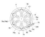
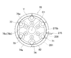
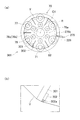
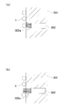
- FIG. 1 It is a schematic block diagram of the winding unit which concerns on 1st Embodiment. It is a schematic block diagram of the accumulator of FIG. It is a top view which shows the positional relationship of the roller of FIG. 2, a slope member, and a winding arm. It is a schematic block diagram of the accumulator of 2nd Embodiment. It is a figure equivalent to FIG. 3 of 2nd Embodiment. It is the figure which showed typically the effect
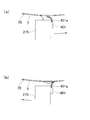
- (A) is a figure equivalent to FIG. 3 of 4th Embodiment
- (b) is the elements on larger scale of the area
- (A) is a schematic block diagram of the accumulator in 7th Embodiment
- (b) is the elements on larger scale of the area
- (A) is the figure equivalent to FIG. 13 of the accumulator in 8th Embodiment,
- (b) is the elements on larger scale of the area
- (A) is the figure equivalent to FIG. 3 of the modification 1
- (b) is the figure equivalent to FIG. 13 of the modification 2.
- the automatic winder according to the first embodiment includes a number of winding units 2 (yarn storage and drawing device, yarn winding device) shown in FIG.
- Each winding unit 2 includes a yarn supplying unit 5, a winding unit 6, a yarn defect detecting unit 7, a yarn joining unit 8, and a yarn storing unit 9.
- the yarn supplying unit 5 (yarn supplying unit) includes a yarn supplying bobbin holding unit 60 for holding the yarn supplying bobbin 21, a yarn unwinding assisting device 12, and a first tension applying device 41. Further, the yarn supplying unit 5 further includes a bobbin supplying device (not shown) for supplying a new yarn supplying bobbin 21 to the yarn supplying bobbin holding unit 60. Examples of the bobbin supply device include a magazine-type supply device and a tray-type supply device. When all the spun yarn Y (hereinafter simply referred to as yarn Y) is pulled out from the yarn supplying bobbin 21 set in the winding unit 2, the yarn supplying unit 5 is held by the yarn supplying bobbin holding unit 60. The empty bobbin is discharged, and the bobbin supply device sequentially supplies new yarn supplying bobbins 21 to the yarn supplying bobbin holding unit 60.
- yarn Y spun yarn Y
- the yarn unwinding assist device 12 lowers the yarn Y from the yarn supplying bobbin 21 by lowering the regulating member 40 covering the core pipe of the yarn supplying bobbin 21 in conjunction with the yarn Y unwinding from the yarn supplying bobbin 21. Assist the cocoon.
- the regulating member 40 comes into contact with the balloon formed on the upper portion of the yarn feeding bobbin 21 by the rotation and centrifugal force of the yarn Y unwound from the yarn feeding bobbin 21, and applies an appropriate tension to the balloon to thereby apply the yarn Y. Assist with unraveling.
- a yarn feeler 37 capable of detecting the presence or absence of the yarn Y is provided.
- the yarn feeler 37 detects that the yarn Y pulled out from the yarn feeding bobbin 21 has run out.
- the first tension applying device 41 applies a predetermined tension to the traveling yarn Y.
- a gate type device in which movable comb teeth are arranged with respect to fixed comb teeth can be used.
- the movable comb teeth can be rotated by a rotary solenoid (not shown) so that the comb teeth are engaged or opened.
- the first tension applying device 41 can apply a certain tension to the yarn Y stored in the accumulator 61 to be described later, and the yarn Y can be wound in an orderly manner in the accumulator 61 and stored.
- the winding unit 6 (unwinding processing unit) includes a cradle (package support unit) (not shown) configured to hold the winding bobbin 22 and a winding unit for traversing the yarn Y and rotating the winding bobbin 22.
- a drum 24 and a second tension applying device 42 are provided.
- the cradle is configured to be able to swing in a direction in which the cradle approaches or separates from the take-up drum 24, whereby the package 30 is brought into contact with or separated from the take-up drum 24.
- a spiral traverse groove 27 is formed on the outer peripheral surface of the winding drum 24, and the yarn Y is traversed by the traverse groove 27.
- the winding drum 24 is driven to rotate by a motor (not shown), thereby rotating the winding bobbin 22 disposed to face the winding drum 24.
- the second tension applying device 42 controls the tension when the yarn Y unwound from an accumulator 61 (to be described later) of the yarn storage unit 9 is wound around the package 30. As a result, the yarn Y drawn from the accumulator 61 is wound on the winding bobbin 22 in a state where an appropriate tension is applied.
- the second tension applying device 42 may be a gate type device in which movable comb teeth are arranged with respect to fixed comb teeth.
- the yarn defect detection unit 7 includes a yarn clearer 15.
- the yarn clearer 15 detects a defect by monitoring the thickness of the yarn Y with an appropriate sensor.
- the yarn clearer 15 can also function as a sensor that simply detects the presence or absence of the yarn Y. Further, the yarn clearer 15 is provided with a cutter 16 for cutting the yarn upstream of the yarn defect when the yarn defect is detected.
- a waxing device 17 for waxing the running yarn Y is disposed on the downstream side of the second tension applying device 42.
- a suction unit (not shown) is provided on the downstream side of the waxing device 17. This suction part is connected to an appropriate negative pressure source and can suck and remove wax wrinkles and lint.
- the yarn joining portion 8 includes a splicer device 14 that performs a yarn joining operation, a lower yarn guide pipe 25, and an upper yarn guide pipe 26.
- the splicer device 14 is used to store the yarn supply section 5 and the yarn storage when the running yarn Y is cut, when a yarn defect occurs, when the yarn Y of the yarn supply bobbin 21 is lost, and the yarn supply bobbin 21 is replaced.
- the yarn Y is divided between the yarn supply unit 5 and the supply of the yarn Y from the yarn supply unit 5 to the yarn storage unit 9 is interrupted, the yarn end on the yarn supply bobbin 21 side and the yarn on the package 30 side It joins the ends.
- a mechanical device, a device using a fluid such as compressed air, or the like can be used as the splicer device 14.
- the lower thread guide pipe 25 is rotatably supported around a shaft 25a positioned below the splicer device 14, and can be rotated by a motor (not shown).
- a suction port 25b is provided at the tip of the lower thread guide pipe 25, and a clamp portion (not shown) is provided in the suction port 25b.
- a negative pressure source (not shown) is connected to the lower thread guide pipe 25, so that a negative pressure is supplied, thereby generating a suction flow for sucking the thread Y into the suction port 25b. .
- the upper thread guide pipe 26 is rotatably supported around a shaft 26a positioned above the splicer device 14, and can be rotated by a motor (not shown).
- a suction port 26b is provided at the tip of the upper thread guide pipe 26, and a clamp portion 26c (see FIG. 2) is provided in the suction port 26b.
- a negative pressure source 120 (see FIG. 2) is connected to the upper thread guide pipe 26, so that a negative pressure is supplied, whereby suction for sucking the thread Y into the suction port 26b is performed. A flow is generated.
- the yarn storage unit 9 includes an accumulator 61 for storing the yarn Y that has been unwound from the yarn supply bobbin 21 and before being wound around the winding bobbin 22.
- the accumulator 61 includes a yarn storage body 70, a winding arm 75, a winding arm motor 76, a speed reducer 77, pulleys 78a to 78c, a shaft 79, and the like.
- the yarn storage body 70 includes six rollers 71, a base material 72, a rotating plate 73, and three slope members 74.
- the base material 72 is a substantially circular plate-like body, and is supported by a tip portion of the output shaft 136 of the winding arm motor 76 via a bearing (not shown).
- the six rollers 71 are arranged on the upper surface of the base material 72 along the virtual circumference R, and the lower end (first end) is pivotally supported on the upper surface of the base material 72 and the upper end (first Two ends) are supported by the rotating plate 73.
- the rotation plate 73 is rotatable about the rotation axis C1 of the winding arm motor 76.
- the rotation plate 73 When the rotation plate 73 is rotated, the upper end of the roller 71 supported by the rotation plate 73 is The yarn storage body 70 moves in the circumferential direction by a distance corresponding to the same central angle.
- the roller 71 When the upper end of the roller 71 is moved in the circumferential direction of the yarn reservoir 70 by rotating the rotary plate 73, the roller 71 is moved from the winding portion of the yarn reservoir 70 as shown in FIG. It is inclined with respect to the yarn storage direction toward the yarn unwinding portion. That is, all the rollers 71 are supported while being inclined with respect to the rotation axis C1.
- the rotating plate 73 is provided with a rubber ring 81 so as to surround the outer peripheral surface thereof, and the yarn Y wound around the roller 71 is interposed between the rotating plate 73 and the rubber ring 81 as described later. It is sent toward the winding unit 6 through the gap. At this time, since the yarn Y is fed between the rotating plate 73 and the rubber ring 81, the fluff of the yarn Y is laid down. Further, since the yarn Y is sandwiched between the rotating plate 73 and the rubber ring 81, a balloon is generated in the yarn Y that is unwound from the roller 71 and travels toward the winding unit 6. Can be prevented.
- a pulley 82 is attached to the lower surface of the roller 71.
- the pulley 82 is a pulley connected to the speed reducer 77 and a speed reducer 77 that reduces and transmits the rotation of the winding arm motor 76 at a predetermined speed reduction ratio.
- the six rollers 71 are all driven rollers driven by the winding arm motor 76, but some of them are connected to the winding arm motor 76. There may be no driven roller.
- the three slope members 74 are attached to the base material 72 so as to be separated from each other by about 120 ° so as to surround the lower ends of the six rollers 71.
- the slope member 74 has a winding auxiliary surface 74 a for smoothly connecting the outer peripheral surfaces of the adjacent rollers 71 at a portion located between the adjacent rollers 71, and the surface of the lower end portion of the roller 71.
- the winding auxiliary surface 74a forms a surface extending substantially continuously along the virtual circumference R. Further, the winding auxiliary surface 74a is inclined so that the upper part comes to the inner side in the radial direction.
- the winding arm 75 (guide member) is for guiding the yarn Y to the lower end portion of the roller 71, and is configured to be rotatable about the rotation axis C1, and the yarn Y can travel inside.
- This is a tubular member in which an internal flow path 128 is formed.
- the winding arm 75 is connected to the outer peripheral surface of the output shaft 136, extends from the outer peripheral surface of the output shaft 136 to the outside in the radial direction so as to wrap around the side of the yarn reservoir 70, and reaches the vicinity of the lower end portion of the roller 71. .
- the winding portion of the yarn storage body 70 has a circular winding outer periphery in a plan view (as viewed from the direction from the first end side to the second end side), and the winding arm 75
- the front end portion is a straight portion 75a extending linearly in the tangential direction of the winding outer periphery in plan view (along the outer peripheral direction of the yarn reservoir 70).
- an opening 75 b that faces the lower end of the roller 71 is formed at the tip of the winding arm 75.
- the opening 75b is inclined with respect to the straight portion and extends along the circumferential direction of the roller 71 and the slope member 74, whereby the opening area of the opening 75b is larger than the area of the internal flow path 128. It has become.
- the winding arm 75 is rotatable about the rotation axis C1, and by rotating counterclockwise in plan view about the rotation axis C1, the winding arm 75 is wound as described later.
- the yarn Y on the yarn supplying portion 5 side guided into the internal flow path 128 of the attached arm 75 is wound around the lower end portions of the six rollers 71 and the slope member 74.
- the yarn Y is tangential to the winding portion of the yarn reservoir 70 in a plan view (as viewed from the direction from the first end side to the second end side) by the straight portion 75a of the winding arm 75. Be guided to.
- the yarn Y is guided by the winding arm 75 along the outer circumferential direction of the yarn reservoir 70.
- the internal flow path 128 of the winding arm 75 communicates with the flow path 144 formed inside the output shaft 136.
- a balancer 145 formed integrally with the output shaft 136 is provided on the opposite side of the winding arm 75 and the output shaft 136.
- the winding arm motor 76 (rotation mechanism) is a position-controllable motor such as a servo motor, a DC brushless motor, or a stepping motor.
- the combination of the winding arm 75 and the winding arm motor 76 corresponds to the winding mechanism according to the present invention.
- a yarn passage 146 communicating with the passage 144 of the output shaft 136, and an upper thread guide pipe that opens into the yarn passage 146 and that extends from the winding arm 75 side.
- a blow-down nozzle 148 having a blow-down flow path 147 formed to be inclined toward the 26th side is provided.
- a pressure air source 151 (air flow generator) is connected to the downflow passage 147 via a connection pipe 149 and a connection pipe 150, and an electromagnetic valve 152 is connected between the connection pipe 149 and the connection pipe 150. Is provided.
- this air flow attracts the yarn end of the yarn Y wound around the roller 71, and at the same time, the winding arm 75 is reversed from the winding time of the yarn Y around the yarn storage body 70. By rotating in the direction, the sucked yarn end is pulled out to the yarn joining portion 8 side. That is, in 1st Embodiment, the winding arm 75 and the winding arm motor 76 which comprise a winding mechanism, the blowing nozzle 148 mutually connected by the connection pipes 149, 150, 151, the pressure air source 151, and a solenoid valve The combination with 152 corresponds to the drawing mechanism according to the present invention.
- a pull-out sensor 154 is provided at the lower end of the blow-down nozzle 148 for detecting that the yarn end of the yarn Y wound in the accumulator 61 is actually pulled out to the yarn joining portion 8 side. Yes.
- the operator of the automatic winder (winding unit 2) unwinds the yarn Y from the yarn feeding bobbin 21, and uses the yarn Y as a yarn unwinding assisting device 12, a yarn feeler 37, a first tension applying device 41, and a yarn clearer 15.
- the accumulator 61, the second tension applying device 42, and the waxing device 17 are set and fixed to the winding bobbin 22.
- the yarn path of the yarn Y in the accumulator 61 is as shown in FIG. That is, the operator passes the yarn Y through the pull-out sensor 154, the yarn passage 146 of the blow-down nozzle 148, the passage 144 of the output shaft 136, and the internal passage 128 of the winding arm 175 in order.
- the operator pulls the yarn Y on the opening 75 b side of the winding arm 75, winds it around the roller 71 and the slope member 74, for example, about 5 to 20 times, and sets it on the second tension applying device 42.
- the yarn Y in FIG. 2 is drawn thick for convenience of explanation and the winding interval is large, but in reality, the roller 71 is always wound around 600 times at a small winding interval. A bundle of warp yarns Y is stored.
- the winding arm 75 is rotated by the winding arm motor 76 and the winding drum 24 is rotated. Then, when the winding arm 75 rotates, the yarn Y of the yarn supplying bobbin 21 is unwound (drawn), and the unwound yarn Y is applied to the lower ends of the six rollers 71 and the three slope members 74. Wrapped across. When the wound yarn Y moves upward along the inclination of the winding auxiliary surface 74a of the slope member 74 and moves further upward than the slope member 74, only the six rollers 71 are wound.
- the six rollers 71 also rotate, and the yarn Y wound around the six rollers 71 is conveyed in the circumferential direction of the roller 71 by the rotating roller 71.
- the roller 71 is inclined with respect to the yarn accumulating direction (the direction of the rotation axis C1) as described above, the circumferential direction of the roller 71 has a vector component from the winding portion toward the unwinding portion.
- the yarn Y wound around the roller 71 moves upward.
- the yarn Y unwound from the yarn feeding bobbin 21 is moved from the lower end (first end, winding side end) to the upper end (second end, The yarn is stored in the yarn storage body 70 in a state of being wound toward the unwinding side end portion.
- the yarn Y stored in the state of being wound around the roller 71 by the rotation of the winding drum 24 is drawn out in order from the upper end by the winding unit 6 and wound around the package 30 while being traversed by the winding drum 24. (Thread processed).
- the lower end portion of the roller 71 around which the yarn Y is wound together with the slope member 74 by the winding arm 75 corresponds to the winding portion according to the present invention, and the winding auxiliary surface 74a of the slope member 74.
- the portion of the roller 71 and the slope member 74 positioned above (on the second end side) the yarn Y wound around the winding portion moves due to the inclination of the roller 71 and the rotation of the roller 71. This corresponds to the storage unit according to the present invention.
- the yarn joining operation in the winding unit 2 will be described.
- the yarn Y of the yarn feeding bobbin 21 is lost.
- the yarn supplying bobbin 21 is replaced, the yarn Y is divided between the yarn supplying unit 5 and the yarn accumulating unit 9, and the supply of yarn from the yarn supplying unit 5 to the yarn accumulating unit 9 is interrupted. . Therefore, in such a case, the winding unit 2 performs the splicing of the divided yarn Y as described below.
- the winding unit 6 pulls out the yarn Y stored in the yarn storage body 70 without stopping the winding of the yarn Y onto the winding bobbin 22 while performing the yarn splicing described below. The winding of the yarn Y onto the winding bobbin 22 is continued.
- the winding arm 75 When it is detected that the traveling yarn has been cut, when a yarn defect is detected, or when it is detected that the yarn Y of the yarn feeding bobbin 21 has run out, the winding arm 75 is rotated. Stop. At this time, the yarn end on the accumulator 61 side reaches the yarn reservoir 70 until the winding arm 75 stops rotating, and winds around the lower end portion of the roller 71 and the slope member 74.
- the winding arm 75 is rotated at a low speed in the direction opposite to that at the time of winding, and the electromagnetic valve 152 is opened, so that the internal flow path 128 of the winding arm 75 and the winding arm motor 76 are opened as described above.
- An air flow from the yarn reservoir 70 side to the upper yarn guide pipe 26 side is generated in the flow channel 144 of the output shaft 136 and the yarn flow channel 146 of the blow-down nozzle 148.
- the yarn end of the yarn Y that has been wound around the yarn reservoir 70 is sucked into the winding arm 75 from the opening 75b by the winding arm 75 that rotates while sucking, and the sucked yarn end becomes the internal flow path 128, the flow. It is drawn out to the upper thread guide pipe 26 side through the path 144 and the thread flow path 146.
- the drawing sensor 154 detects that the yarn end has been drawn to the upper yarn guide pipe 26 side, the electromagnetic valve 152 is closed.
- the suction port 26b of the upper thread guide pipe 26 is opened, the thread end of the pulled-out thread is sucked and captured, and the captured thread end is gripped by the clamp portion 26c. Then, while the winding arm 75 is rotated at a low speed, the upper thread guide pipe 26 holding the thread end by the clamp portion 26c is turned about 180 ° about the shaft 26a, and the thread end on the thread storage body 70 side is rotated. After setting the splicer device 14, the low-speed rotation of the winding arm 75 is stopped.
- the yarn end of the yarn Y existing around the yarn feeler 37 is sucked and captured by the lower yarn guide pipe 25, and the yarn Y is set in the splicer device 14. Then, the splicer device 14 performs a yarn splicing operation between the set yarn end on the accumulator 61 side and the yarn end on the yarn feeding unit 5 side.
- the distal end portion of the winding arm 75 extends linearly in the tangential direction of the winding outer periphery of the winding portion in plan view. Since the yarn Y is guided in this tangential direction, the yarn end on the accumulator 61 side is also guided in the tangential direction by the winding arm 75 when the yarn Y is divided. Is done.
- the yarn end guided by the yarn reservoir 70 does not collide with the roller 71 or the slope member 74 and jumps upward, and the lower end portion of the roller 71 where the yarn Y is guided by the winding arm 75 or It remains in the vicinity (winding portion) of the slope member 74, that is, at a position where it can be sucked from the opening 75b. Therefore, the yarn end can be reliably sucked and pulled out.
- the yarn end is held at the lower end portion of the roller 71 or in the vicinity of the slope member 74, the yarn end is wound around and stored in a portion (storage portion) above the slope member 74 of the roller 71.
- the yarn end can be sucked without affecting the yarn Y.
- the opening 75 b of the winding arm 75 is inclined with respect to the straight portion 75 a and extends along the circumferential direction of the yarn reservoir 70, so that the opening area of the opening 75 b can be reduced. It is larger than the area, and comes closer to the surface of the lower end portion of the roller 71 and the winding auxiliary surface 74a, and the yarn end can be sucked more reliably.
- the yarn Y wound around the roller 71 is viewed in a plan view (viewed from the direction from the first end side to the second end side).
- the winding shape is substantially hexagonal, and the wound yarn Y is positioned inside the portion between the rollers 71 than the portion hanging on the rollers 71. Therefore, when the yarn end is located between the rollers 71, the distance between the winding arm 75 and the yarn end is larger than when the yarn end is located on the roller 71, There is a possibility that the yarn Y cannot be sucked.
- the slope member 74 is provided between the six rollers 71, and the surface of the lower end portion of the roller 71 and the winding auxiliary surface 74a of the slope member 74 are virtual circles. Since the surface extending substantially continuously along the circumference R is formed, the winding shape of the yarn Y wound around the roller 71 and the slope member 74 by the winding arm 75 is substantially circular. Become. Therefore, when the yarn end is located on the roller 71 and when the yarn end is located on the slope member 74, the distance between the winding arm 75 and the yarn end is substantially the same. Yes. Accordingly, the yarn Y can be sucked from the yarn reservoir 70 more reliably.
- the surface of the lower end portion of the roller 71 and the winding auxiliary surface 74a form a surface extending substantially continuously along the virtual circumference R, and the yarn wound around the yarn reservoir 70 at the time of yarn division. Since the end comes on either the surface of the roller 71 or the winding auxiliary surface 74a, the yarn end can be sucked more reliably than when the yarn end is in the air.
- a winding mechanism for winding the yarn Y around the yarn reservoir 70 and a drawer for sucking and pulling out the yarn end of the yarn Y wound around the yarn reservoir 70
- the winding arm 75 constituting the mechanism extends in a direction (tangential direction) along the outer periphery of the yarn reservoir 70 in a plan view, and the opening 75b is inclined with respect to the straight portion 75a.
- the drawing auxiliary portion for facilitating the suction of the yarn Y that is, the drawing operation of the yarn Y, by making the opening area larger than the area of the internal flow path 128 by extending in the circumferential direction of 70. Doubles as
- the slope member 74 that makes the winding shape of the yarn Y substantially circular also constitutes a drawing auxiliary portion for facilitating the successful pulling operation of the yarn Y.
- an accumulator 261 is provided instead of the accumulator 61 (see FIG. 2).
- the accumulator 261 is different from the accumulator 61 in that the shape of the winding arm 275 is different from that of the winding arm 75 (see FIG. 2) and that the annular member 201 is provided.
- the winding arm 275 extends in the direction substantially perpendicular to the outer circumferential direction of the yarn reservoir 70 in plan view. Moreover, the opening 275b of the winding arm 275 has the same cross-sectional area as the internal flow path 228.
- the annular member 201 is a thin plate made of an elastic material such as rubber, and is disposed so as to surround the lower end portion of the roller 71 and the upper end portion of the slope member 74.
- the surface of 71 and the winding auxiliary surface 74a of the slope member 74 are arranged in contact with each other.
- a gap smaller than the diameter of the yarn Y is provided between the inner peripheral end of the annular member 201 and the roller 71 and the slope member 74.
- the annular member 201 is fixed to a frame (not shown) of the accumulator 261.
- the entire annular member 201 is made of an elastic material.
- the annular member 201 only needs to be made of an elastic material at least at a portion including the inner peripheral end thereof.
- the annular member 201 is arrange
- the yarn Y that moves upward (toward the storage portion) contacts the annular member.
- the yarn Y since the tension is applied to the yarn Y by the first tension applying device 41, as shown in FIG. 6A, the yarn Y is elastically deformed by the annular member 201 made of an elastic material. Push and move upwards.
- the winding arm 275 is also stopped. However, until the winding arm 275 stops, the yarn end on the accumulator 261 side is moved to the winding arm. It is guided to the yarn reservoir 70 by 275. At this time, the yarn end is guided in a direction substantially orthogonal to the surface of the roller 71 or the winding auxiliary surface 74a of the slope member 74 in a plan view. Therefore, the yarn end may collide with the surface of the roller 71 or the slope member 74 and try to jump upward.
- the annular member 201 prevents the yarn end from jumping upward, and the yarn end is held near the lower end of the roller 71 or the slope member 74. Thereby, the yarn end can be reliably sucked from the winding arm 275.
- the annular member 201 in place of the winding arm 75 (see FIG. 2), constitutes the drawer auxiliary portion according to the present invention.
- an accumulator 361 is provided instead of the accumulator 261 (see FIG. 4) of the second embodiment.
- the accumulator 361 has a point that six plate members 301 are provided instead of the slope member 74 (see FIG. 4), and a yarn end from each yarn Y wound around the yarn reservoir 70 around each plate member 301.
- the point different from the accumulator 261 is that a yarn end separation brush 302 for separation is provided.
- the six plate members 301 (winding shape adjusting members, plate-like members) are arranged between the six rollers 71 so that the surface direction thereof is parallel to the radial direction of the yarn reservoir 70 in plan view.
- the outer peripheral end of the plate member 301 is located at substantially the same position as the outer peripheral end of the roller 71 in the radial direction of the yarn reservoir 70.
- the plate member 301 is long enough to face at least the lower end of the roller 71 around which the yarn Y is wound by the winding arm 275 with respect to the vertical direction (the direction perpendicular to the plane of FIG. 7).
- the yarn end separation brush 302 is a brush whose tip portion 302a (hair portion) is made of an elastic material, and the tip portion protrudes outside the plate member 301 in the radial direction of the yarn reservoir 70.
- the plate members 301 are arranged.
- the thread end separation brush 302 is provided on each of the six plate members 301, but the thread end separation brush 302 may be provided on only some of the plate members 301. Good.
- yarn Y is wound by the winding arm 275 so that the lower end part of the roller 71 and the board member 301 may be straddled.
- the yarn Y moves upward by the rotation of the roller 71, the yarn Y comes into contact with the tip end portion 302 a of the yarn end separation brush 302 protruding from the plate member 301.
- the yarn Y elastically deforms the tip end portion 302a of the yarn end separation brush 302 as shown in FIG. To move upwards.
- the yarn end wound around the yarn reservoir 70 comes into contact with the tip of the yarn end separation brush 302, but no tension is applied to the yarn end, and the yarn end separation brush. There is not enough force to elastically deform and push the tip 302a of 302. Therefore, as shown in FIG. 8B, the yarn end does not move above the yarn end separation brush 302.
- the yarn end is separated from the wound yarn Y and stays in the vicinity of the lower end portion of the roller 71 or the plate member 301, and the yarn end can be reliably sucked from the winding arm 275.
- the winding shape of the yarn Y is a substantially regular hexagon.
- the roller 71 and the plate member are wound. Since the yarn Y is wound across 301, the wound shape of the wound yarn Y becomes a substantially regular dodecagon and approaches a circular shape.
- the distance between the winding arm 75 and the yarn end does not increase, and the yarn end can be reliably sucked. it can.
- the plate member 301 and the yarn end separation brush 302 are the drawing auxiliary portion according to the present invention.
- an accumulator 461 is provided instead of the accumulator 261 (see FIG. 4).
- the accumulator 461 is different from the accumulator 261 in that the accumulator 461 includes a yarn end scraping brush 401.
- the yarn end scraping brush 401 has a tip 401a (hair portion) made of an elastic material, and as shown in FIG. 9, the direction of rotation when the winding arm 275 is wound (counterclockwise in FIG. 9). In the state where the winding arm 275 is not rotating, the tip 401 a is in contact with the lower end of the roller 71 or the slope member 74.
- the winding arm 275 is rotated around the rotation axis C1 (the winding center of the yarn Y in the yarn storage body 70) (the winding arm 275 and the yarn storage body 70 are relatively rotated), and the yarn storage body 70 is rotated.
- the rotational speed of the winding arm 275 is fast to some extent (for example, about 3000 rpm), so that the tip 401a of the yarn end scraping brush 401 is wound as shown in FIG. It falls down due to the wind pressure generated by the rotation of the attached arm 275 and is separated from the roller 71 and the slope member 74. Thereby, it can prevent that the front-end
- the rotation speed of the winding arm 275 is slow (for example, 50 rpm or less). Therefore, the tip end portion 401a of the yarn end scraping brush 401 does not fall down due to the wind pressure, and is in contact with the roller 71 and the slope member 74 as shown in FIG.
- the yarn end of the yarn Y wound around the yarn reservoir 70 may be in a state of being stuck to the yarn Y already wound around the yarn reservoir 70.
- the yarn end stuck to the yarn Y can be scraped off. Thereby, the yarn end can be reliably sucked from the winding arm 275.
- the yarn end scraping brush 401 is provided on the winding arm 275, the yarn end scraped by the yarn end scraping brush 401 comes in the vicinity of the winding arm 275. Therefore, the yarn end can be reliably sucked from the winding arm 275.
- the yarn end scraping brush 401 constitutes a drawing auxiliary portion according to the present invention.
- the winding arm 275 provided with the yarn end scraping brush 401 rotates along the outer periphery of the yarn storage body 70 as in the case of the fourth embodiment, the winding arm 275 is relatively simple.
- the yarn storage body 70 is separated from the yarn storage body 70 when the yarn Y is wound around the yarn storage body 70, and the yarn storage body 70 is pulled out when the yarn end is pulled out before yarn joining.
- the yarn end scraping member to be contacted can be configured.
- the accumulator is provided with the yarn reservoir 70 (see FIG. 2 and the like) including the six rollers 71 around which the yarn Y is wound.
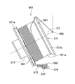
- the accumulator 561 includes a rotary storage drum 571, a rotary storage drum motor 572, a yarn guide member 573, a blow-down nozzle 574, a yarn path forming member 575, and the like.
- the rotary storage drum 571 is a drum that can rotate around the rotation axis C2. As will be described later, when the rotary storage drum 571 is rotated in one direction, the yarn Y is unwound from the yarn supplying bobbin 21 (see FIG. 1). The yarn Y that has been unwound and wound around the rotary storage drum 571 is stored in the rotary storage drum 571. That is, in the fifth embodiment, the rotary storage drum 571 constitutes both the yarn storage body and the winding mechanism according to the present invention.
- the rotary storage drum 571 has tapered portions 571a and 571b whose diameters become smaller toward the opposite end portions, respectively, and between the tapered portion 571a and the tapered portion 571b.
- This portion is a straight portion 571c having a substantially constant diameter.
- a rubber ring 581 such as a rubber band or an O-ring is wound around the upper right end portion of the straight portion 571c of the rotary storage drum 571, and the rubber ring 581 rotates integrally with the rotary storage drum 571. Then, as will be described later, the yarn Y drawn from the rotary storage drum 571 passes through the gap between the straight portion 571c and the rubber ring 581 and is sent toward the winding portion 6 through the yarn guide 582. At this time, the yarn Y is fed between the straight portion 571c and the rubber ring 581 while being nipped between the straight portion 571c and the rubber ring 581. Further, since the yarn Y is sandwiched between the straight portion 571c and the rubber ring 581, a balloon is generated in the yarn Y that is unwound from the rotary storage drum 571 and travels toward the winding portion 6. Can be prevented.
- the upper right end portion of the rotary storage drum 571 is the tapered portion 571b, so that the rubber ring 581 is prevented from falling off from the rotary storage drum 571 to the upper right.
- the rotary storage drum motor 572 (rotation mechanism) is a position-controllable motor such as a DC brushless motor, a stepping motor, or a servo motor, and rotates the rotary storage drum 571 in both directions.
- the yarn guide member 573 is a tubular member in which an internal flow path 573a is formed, and the tip portion of the yarn guide member 573 is a rotary storage drum 571 as viewed from the direction of the rotation axis C2.
- the linear portion 573b extends linearly in the tangential direction, and is bent in the radial direction of the rotary storage drum 571 at the end opposite to the linear portion 573b and connected to the blow-down nozzle 574.
- An opening 573c is formed at the tip of the straight portion 573b.
- the opening 573c is inclined with respect to the linear portion 573b and extends along the circumferential direction of the tapered portion 571a.
- the blow-down nozzle 574 is disposed on the right side of the yarn guide member 573 in the drawing, and opens into the yarn channel 546 connected to the internal channel 573a of the yarn guide member 573, and the yarn channel 546. And a blow-down channel 547 formed to be inclined with respect to the channel 546.
- a pressure air source 551 is connected to the downflow passage 547 via a connection pipe 549 and a connection pipe 550, and an electromagnetic valve 552 is provided between the connection pipe 549 and the connection pipe 550.
- the yarn path forming member 575 forms the yarn path 528, and is disposed between the suction port 26b of the upper thread guide pipe 26 and the blow-down nozzle 574.
- the yarn path 528 extends almost directly from the lower end located immediately above the suction port 26b of the upper yarn guide pipe 26, and at its upper end, bends to the upper left in FIG. Is opposed to the lower right end of the yarn flow path 546 of the blow-down nozzle 574.
- the rotary storage drum 571 and the rotary storage drum motor 572 are connected to each other, the yarn guide member 573, the blow-down nozzle 574, the yarn path forming member 575, the connection pipes 549 and 550, the pressure air source.
- a combination of the 551 and the electromagnetic valve 552 corresponds to the drawing mechanism according to the present invention.
- a pull-out sensor 554 capable of detecting that the yarn end of the yarn Y wound around the accumulator 561 is actually pulled out to the yarn joining portion 8 side is provided at the lower end of the yarn path forming member 575. Yes.
- the yarn Y is unwound from the yarn supplying bobbin 21, and the yarn Y is set as shown in FIG. 11 in order to wind the unwound yarn Y around the winding bobbin 22.
- the rotary storage drum motor 572 rotates the rotary storage drum 571 and the winding drum 24 (see FIG. 1).
- the yarn Y is unwound from the yarn supplying bobbin 21 (see FIG. 1), and the unwound yarn Y is in the direction of the rotation axis C2 of the rotary storage drum 571 (the direction from the first end side to the second end side). ) Is guided in the tangential direction of the rotary storage drum 571 and wound around the taper portion 571a (winding portion). The yarn Y wound around the taper portion 571a moves toward the straight portion 571c along the inclined surface of the taper portion 571a, and is stored in the straight portion 571c (storage portion).
- the rotary storage drum 571 has an end on the taper portion 571b side from the end on the taper portion 571a side (first end) along the direction of the rotation axis C2 (direction from the first end side toward the second end side).
- the yarn Y is stored in a state where the yarn Y is wound toward the (second end).
- the rotary storage drum 571 is rotated at a low speed in the direction opposite to the time when the yarn Y is wound, and the electromagnetic valve 552 is opened, so that the internal flow path 573a inside the yarn guide member 573, the yarn, as described above.
- An air flow from the rotary storage drum 571 side toward the upper thread guide pipe 26 side is generated in the flow path 546 and the blow-down flow path 547.
- the yarn end of the yarn Y wound around the rotary storage drum 571 (tapered portion 571a) is sucked from the opening 573c, and the sucked yarn ends are taken as the internal flow path 573a, the thread flow path 546, and the blow-down flow path 547. And is pulled out to the upper thread guide pipe 26 side.
- the drawing sensor 154 detects that the yarn end has been drawn to the upper yarn guide pipe 26 side, the electromagnetic valve 552 is closed.
- the upper yarn guide pipe 26 and the lower yarn guide pipe 25 are used to bring the yarn end of the yarn Y on the rotary storage drum 571 side and the periphery of the yarn feeler 37, respectively.
- the yarn end of the existing yarn Y is set in the splicer device 14 and the splicing operation is performed by the splicer device 14.
- the rotary storage drum 571 is rotated, and the winding of the yarn Y around the rotary storage drum 571 is resumed.
- the yarn stored in the rotary storage drum 571 is not stopped without stopping the winding of the yarn Y onto the winding bobbin 22 during the yarn splicing. Y is pulled out and the winding of the yarn Y onto the winding bobbin 22 is continued.
- the linear portion 573b of the yarn guide member 573 is in the tangential direction of the rotary storage drum 571 as viewed from the direction of the rotation axis C2. Since the yarn Y extends in a straight line and is guided in this tangential direction, the yarn end on the rotary storage drum 571 side is also moved by the yarn guide member 573 when the yarn Y is divided as in the first embodiment. It will be guided in the tangential direction.
- the yarn end guided to the rotary storage drum 571 does not collide with the taper portion 571a and jumps up to the straight portion 571c side (upper right in the figure), and is guided by the yarn guide member 573.
- the yarn end In the vicinity of the tapered portion 571a, that is, in a position where suction can be performed from the opening 573c of the yarn guide member 573. Therefore, the yarn end can be reliably sucked.
- the opening 573c of the yarn guide member 573 is inclined with respect to the linear portion 573b and extends along the circumferential direction of the rotary storage drum 571 (tapered portion 571a), whereby the opening area of the opening 573c is It is larger than the area of the internal flow path 573a and comes to a position close to the tapered portion 571a, so that the yarn end can be sucked more reliably.
- the opening 573c at the tip thereof extends along the circumferential direction of the taper portion 571a, as viewed from the direction of the rotation axis C2. Also serving as a drawer auxiliary part according to the present invention.
- an accumulator 661 is provided instead of the accumulator 561 (see FIG. 11).
- the accumulator 661 is different from the accumulator 561 in that the shape of the yarn guide member 673 is different from that of the yarn guide member 573 (see FIG. 11) and that the annular member 601 is provided.
- the yarn guide member 673 is not bent in the middle, and extends straight from the connecting portion with the blow-down nozzle 574 in a direction perpendicular to the surface of the tapered portion 571a. Yes.
- the annular member 601 is a thin plate member made of an elastic material similar to the annular member 201 (see FIG. 4), and is disposed so as to surround the upper end portion of the tapered portion 571a. Further, the inner peripheral end of the annular member 601 is in contact with the tapered portion 571a. Alternatively, a gap smaller than the diameter of the yarn Y is formed between the inner peripheral end of the annular member 601 and the tapered portion 571a.
- the annular member 601 should just be comprised by the elastic material at least the part including the inner peripheral end similarly to the annular member 201 (refer FIG. 4).
- the yarn Y wound around the tapered portion 571a is displaced by elastically deforming the annular member 601 and moves toward the straight portion 571c.
- the yarn end guided to the taper portion 571a is guided in a direction perpendicular to the surface of the taper portion 571a. Therefore, the yarn end collides with the taper portion 571a and the straight portion 571c side. May try to jump up.
- the tension is not applied to the yarn end that is about to jump upward, and there is not enough force to elastically deform and push the annular member 601. Therefore, in the case of the second embodiment Similarly, the annular member 601 prevents the yarn end from jumping up toward the straight portion 571c. Thereby, the yarn end is held in the vicinity of the tapered portion 571a, and the yarn end can be reliably sucked from the yarn guide member 673. That is, in the sixth embodiment, the annular member 601 serves as a drawer auxiliary portion according to the present invention.
- the accumulator 761 according to the seventh embodiment is the same as the accumulator 661 according to the sixth embodiment except that a thread end separation brush 701 is provided instead of the annular member 601.
- the yarn end separation brush 701 has a tip portion 701a (hair portion) made of an elastic material similar to that of the yarn end separation brush 302 (see FIG. 7), and is formed on the surface of the tapered portion 571a as shown in FIG.
- the tip portion 701a protrudes from the surface of the tapered portion 571a by being disposed in the recessed portion 571d.
- the yarn Y wound around the taper portion 571a is displaced by elastically deforming the tip portion of the yarn end separation brush 701, and is moved to the straight portion 571c. Move towards.
- the yarn end wound around the taper portion 571a comes into contact with the tip portion 701a of the yarn end separation brush 701, but tension is applied to the yarn end.
- the yarn end does not move to the straight portion 571c side of the yarn end separation brush 701 as in the case of the third embodiment.
- the taper portion 571a is fastened. That is, in the seventh embodiment, the yarn end separation brush 701 is a drawing auxiliary portion according to the present invention.
- an accumulator 861 according to the eighth embodiment includes a yarn end scraping brush 801 instead of the annular member 601 in the accumulator 661 according to the sixth embodiment.
- the yarn end scraping brush 801 has a tip portion 801a (hair portion) made of an elastic material. 673.
- the thread end scraping brush 801 is movable in both directions along the thread guide member 673 as indicated by an arrow in FIG.
- the taper portion 571a can be contacted and separated.
- the thread end scraping brush 801 can be moved in this way, unlike the fourth embodiment, the thread guide member 673 provided with the thread end scraping brush 801 does not rotate by itself, but the tip 801a. This is because it cannot be separated from the taper portion 571a by the wind pressure.
- the rotary storage drum 571 is rotated around the rotation axis C2 (the winding center of the yarn Y in the rotary storage drum 571) (relative rotation with respect to the yarn guide member 573 and the rotary storage drum 571).
- the yarn end scraping brush 801 is moved to a position where the tip portion does not contact the taper portion 571a, and when the yarn end wound around the taper portion 571a is pulled out, the yarn end The end scraping brush 801 is moved to a position where the tip portion contacts the tapered portion 571a.
- the tip end portion 801a of the yarn end scraping brush 801 is prevented from coming into contact with the wound yarn Y and damaging the yarn Y. Can do. Further, when pulling out the yarn end, the yarn end can be reliably sucked by scraping the yarn end stuck to the yarn Y wound around the taper portion 571a by the yarn end scraping brush 801.
- the yarn end scraping brush 801 corresponds to the drawing auxiliary portion according to the present invention.
- the linear portion 75 c located at the tip of the winding arm 75 extends in the radial direction of the yarn storage body 70.
- the axis A can be rotated around the axis A, whereby the direction of the straight portion 75c can be changed.
- the winding arm 75 is rotated to rotate the yarn.
- the winding direction of the yarn Y when winding the yarn Y around the reservoir 70 is limited to one direction (in the first embodiment, the counterclockwise direction in FIG. 3).
- the linear portion 573d of the yarn guide member 573 is configured to be rotatable about an axis A2 extending in the radial direction of the rotary storage drum 571.
- the position of the straight line portion 573d can be switched between the position indicated by the solid line in the figure and the position indicated by the two-dot chain line in the figure rotated about 180 degrees around the axis A2 from this position.
- the yarn Y may be wound around the rotary storage drum 571 in either direction (Modification 2).
- the opening area 75 b of the winding arm 75 extends along the circumferential direction of the yarn reservoir 70, so that the opening area is larger than the area of the internal flow path 128.
- the opening 75 b may extend in a direction shifted from the circumferential direction of the yarn reservoir 70, and the cross-sectional area thereof may be larger than the cross-sectional area of the internal flow path 128.
- the opening 75 b may extend in the radial direction of the yarn reservoir 70, so that the opening area may be substantially the same as the area of the internal flow path 128.
- the annular member 201 has an inner peripheral end that is in contact with the roller 71 and the slope member 74 or a gap that is smaller than the diameter of the yarn Y between the roller 71 and the slope member 74.
- the annular member 201 may be arranged so that a gap larger than the diameter of the yarn Y is formed between the inner peripheral end thereof and the roller 71 and the slope member 74.
- the annular member 601 may be arranged so that a gap larger than the diameter of the yarn Y is formed between the inner peripheral end and the tapered portion 571a.
- the yarn end separation brushes 302 and 701 are provided to separate the yarn end from the wound yarn Y.
- the member for separating the yarn end is a brush. As long as it can be pushed away by the wound yarn Y, it may be another member such as a thin plate-shaped member made of an elastic material.
- the yarn end is limited to a portion made of an elastic material that can be pushed away by the wound yarn Y. Absent.
- a yarn end scraping brush 401 is provided to scrape the yarn end from the yarn Y wound around the roller 71 and the slope member 74.
- the yarn is wound by wind pressure.
- the tip end portion 401a of the end scraping brush 401 falls and does not come into contact with the roller 71 and the slope member 74.
- the present invention is not limited to this, and the yarn end scraping brush 401 is not limited to the yarn end scraping brush of the eighth embodiment. Similar to the output brush 801, it may be movable toward and away from the yarn reservoir 70 by moving along the winding arm 75.
- the member for scraping the yarn end is not limited to the brush, and the yarn end can be scraped off, for example, a member having a thin tip. Another possible member may be used.
- the tip ends 401a and 801a of the yarn end scraping brushes 401 and 801 are connected to the yarn storage body 70 and
- the tip portion 401a, 801a may always be in contact with the yarn storage body 70 and the rotary storage drum 571.
- the slope member 74 is disposed between the rollers 71.
- the plate member 301 is disposed between the rollers 71.
- the plate member 301 may be disposed between the rollers 71, and in the third embodiment, the slope member 74 may be disposed between the rollers 71. .
- the single plate member 301 is not limited to be disposed between the rollers 71, and a plurality of plate members 301 are disposed between the rollers 71. It may be arranged.
- a slope member 74 such as a driven roller between the rollers 71 is used.
- a member other than the plate member 301 may be arranged.
- a slope member 74 or a plate for bringing the winding shape of the yarn Y close to a circle as a drawing auxiliary portion In addition to the member 301 being provided, only one of the winding arm 75 having the linear portion 75a, the annular member 201, the yarn end separation brush 302, and the yarn end scraping brush 401 is provided. However, it is not limited to this.
- neither the slope member 74 nor the plate member 301 is provided as the drawing auxiliary portion, and any one of the winding arm 75, the annular member 201, the yarn end separation brush 302, and the yarn end scraping brush 401 is provided. Only may be provided. Two or more of the winding arm 75, the annular member 201, the yarn end separation brush 302, and the yarn end scraping brush 401 may be provided.
- the yarn guide member 573 having the straight portion 573b, the annular member 601, and the yarn end separation brush are used as the drawing auxiliary portion. Only one of 701 and the yarn end scraping brush 801 is provided, but two or more of these may be provided.
- the yarn reservoir that stores the yarn Y is provided with a plurality of rollers 71 and the case that is provided with the rotary storage drum 571 has been described.
- a substantially cylindrical member that does not rotate itself such as another member that can store the yarn Y in a state of being wound from one end to the second end along one direction. Good.
- the winding arms 75 and 175 and the yarn guide members 573 and 673 are tubular members, but these members are not limited to being tubular.
- the yarn ends are sucked using the winding arms 75 and 175 for guiding the yarn Y and the yarn guide members 573 and 673 when the yarn Y is wound.
- the present invention is not limited thereto, and a dedicated member for sucking the yarn end may be provided separately from the winding arms 75 and 175 and the yarn guide members 573 and 673.
- the yarn end may be sucked at a position other than the lower end of the yarn reservoir 70 and the vicinity of the tapered portion 571a where the yarn Y is guided when the yarn Y is wound.
- the yarn end may be fastened in the vicinity of the suction position of the yarn end by a drawing auxiliary portion.
- the yarn end wound around the yarn storage body 70 or the rotary storage drum 571 is drawn out by suction.
- the present invention is not limited to this.
- the yarn end may be grasped and pulled out.
- the yarn splicing section 8 is not provided, and the operator may manually perform the splicing operation.
- the present invention is applied to the yarn winding device that temporarily stores the yarn Y unwound from the yarn supplying bobbin 21 in the yarn storage body, draws the yarn Y stored in the yarn storage body, and winds the yarn Y on the winding bobbin 22.
- the present invention is not limited to this, but the yarn drawn out from the yarn supply unit is temporarily stored in the yarn reservoir, and the yarn stored in the yarn reservoir is pulled out to take up the winding bobbin 22. It is also possible to apply the present invention to a yarn accumulating / drawing device other than the winding device that performs the above process.
Landscapes
- Engineering & Computer Science (AREA)
- Textile Engineering (AREA)
- Forwarding And Storing Of Filamentary Material (AREA)
- Spinning Or Twisting Of Yarns (AREA)
- Replacing, Conveying, And Pick-Finding For Filamentary Materials (AREA)
Abstract
糸貯留部に貯留された糸の糸端を確実に引き出す。 給糸部から糸貯留体70に供給される糸Yと、糸貯留体70に巻き付けられた状態で貯留された糸Yとが分断されたときには、糸貯留体70に糸Yを巻き付けるための管状の巻付アーム75に給糸部側に向かう空気流を発生させることにより、糸貯留体70に巻き付いた糸端を吸引して引き出し、給糸部側の糸端との糸継を行う。巻付アーム75の先端部は、平面視での糸貯留体70の接線方向に延びている。また、糸貯留体70においては、巻付アーム75により、仮想円周Rに沿って配列された6本のローラ71の下端部と、ローラ71の間に配置されたスロープ部材74の巻付補助面74aとにまたがって糸Yが巻き付けられる。ローラ71の下端部の表面と巻付補助面74aとは、仮想円周Rに沿ってほぼ連続的に延びた面を形成しており、平面視での糸Yの巻付形状がほぼ円形となっている。
Description
本発明は、糸供給部から引き出した糸を一時的に糸貯留体に貯留し、糸貯留体に貯留された糸を引き出して糸処理を行う糸貯留引出装置及び糸巻取装置に関する。
特許文献1に記載の糸巻取装置(巻取ユニット)においては、給糸ボビン保持部に保持された給糸ボビンから解舒した糸を、貯留ガイドアームにより糸貯留体(貯留部)に巻き付けることで糸貯留体に一旦貯留し、糸貯留体に貯留された糸を巻き取ってパッケージを形成している。
そして、糸の巻取中において、糸欠陥が検出されたとき、給糸ボビンの糸がなくなって新しい給糸ボビンに交換されるときなどには、糸貯留体に糸を巻き付けるための貯留ガイドアームの回転を停止させることによって、糸貯留体側の糸端を、貯留ガイドアームに糸を導入するための導入孔から垂れ下がった状態にする。そして、垂れ下がった糸端を下流側糸案内パイプにより捕捉してスプライサ装置に案内するとともに、給糸ボビン側の糸端を上流側糸案内パイプにより捕捉してスプライサ装置に案内し、スプライサ装置によってこれらの糸端の糸継を行う。
このとき、糸貯留体に糸が貯留されているため、糸貯留体に貯留された糸を引き出して糸の巻取を継続することができ、これにより、糸の巻取を停止させることなく糸継を行うことができる。
しかしながら、特許文献1では、給糸ボビンからの糸の解舒速度が速い場合などには、上述したように、糸欠陥が検出されたとき、給糸ボビンの糸がなくなって新しい給糸ボビンに交換されるときなどに、貯留ガイドアームの回転を停止させても、糸欠陥や給糸ボビンの糸がなくなったことが検出されてから貯留ガイドアームの回転を停止させるまでの間に、糸端が糸貯留体に到達して糸貯留体に巻き付いてしまう。すなわち、糸貯留体側の糸端を、導入孔から垂れ下がった状態にすることができないことがある。
そのため、このような場合には、糸貯留体に巻き付いた糸端を、導入孔から引き出した上で、下流側糸案内パイプによって糸貯留体側の糸端を捕捉する必要ががある。
本発明の目的は、糸貯留体側の糸端を確実に引き出すことが可能な糸貯留引出装置及び糸巻取装置を提供することである。
第1の発明に係る糸貯留引出装置は、糸供給部と、前記糸供給部の糸を、第一端から第二端に向けて巻き取って貯留する糸貯留体と、前記糸貯留体に貯留された糸を前記第二端から解舒して処理を行う解舒処理部と、前記糸供給部から前記糸貯留体への糸の供給が中断され、前記糸貯留体に糸端が巻き取られた場合に、前記糸貯留体に巻き取られた糸端を前記糸貯留体の前記第一端側から引き出す引出機構と、前記引出機構による前記糸貯留体に巻き取られた糸端の引き出し作業を補助する引出補助機構と、を備えたことを特徴とする。
本発明によると、糸供給部から糸貯留体への糸の供給が中断されたときに、解舒処理部において糸貯留体に貯留された糸を第二端から引き出して処理を行いつつ、引出機構により糸貯留体に巻き取られた糸端を第一端側から引き出すことができる。
さらに、引出補助部によって、引出機構による糸端の引き出し作業が補助されるため、糸貯留体に巻き付いた糸端を確実に引き出すことができる。
第2の発明に係る糸貯留引出装置は、第1の発明に係る糸貯留引出装置において、前記給糸部と前記糸貯留体との間に配置されており、前記引出機構により引き出された前記糸貯留体側の糸端と、前記給糸部側の糸端との糸継を行う糸継部をさらに備えたことを特徴とする。
本発明によると、糸供給部側の糸の糸端と、引出機構により引き出した糸貯留体側の糸の糸端とを、糸継部により糸継することができる。
第3の発明に係る糸貯留引出装置は、第1又は第2の発明に係る糸貯留引出装置において、前記引出機構は、前記糸端を吸引することによって引き出し、
前記引出補助部は、前記糸端を、前記引出機構により吸引可能な位置に留めることを特徴とする。
前記引出補助部は、前記糸端を、前記引出機構により吸引可能な位置に留めることを特徴とする。
本発明によると、引出機構が糸端を吸引して引き出す場合に、引出補助部によって、糸端を、引出機構により吸引可能な位置に留めることにより、確実に糸端を引き出すことができる。
第4の発明に係る糸貯留引出装置は、第3の発明に係る糸貯留引出装置において、前記糸貯留体は、糸が巻き付けられる巻付部と、前記巻付部の前記第二端側に設けられた、前記巻付部に巻き付けられた糸が移動してきて貯留される貯留部とを備え、前記引出補助部は、前記糸端を前記巻付部に留め、前記引出機構は、前記引出補助部により前記巻付部に留められた前記糸端を吸引することを特徴とする。
本発明によると、糸端が糸貯留体の巻付部に留められるため、糸貯留体の貯留部に巻き付けられた糸に影響を与えることなく、糸端の引出を行うことができる。
第5の発明に係る糸貯留引出装置は、第4の発明に係る糸貯留引出装置において、前記給糸部から引き出した糸を前記巻付部に巻き付ける巻付機構をさらに備え、前記巻付機構は、前記給糸部から引き出した糸を前記巻付部に案内する案内部材を備え、前記引出機構が、前記巻付機構と共通の前記案内部材と、前記案内部材に、前記糸貯留体側から前記給糸部側に向かう空気流を発生させる空気流発生装置とを備え、前記案内部材が、前記巻付機構による糸の巻付時に、前記第一端側から第二端側に向かう方向から見て前記糸貯留体の外周方向に沿ってに糸を案内するように構成されていることで前記引出補助部を兼ねていることを特徴とする。
本発明によると、第一端側から第二端側に向かう方向から見て糸貯留体の外周方向に沿って糸を案内して糸を巻き付けるので、糸が分断されたときに、糸端が糸処理部側に跳ね上がらずに、引出機構により吸引可能な巻付部に留まる。したがって、引出機構により確実に糸端を引き出すことができる。
第6の発明に係る糸貯留引出装置は、第5の発明に係る糸貯留引出装置において、前記糸貯留体の巻付部は、前記第一端側から第二端側に向かう方向から見て、円形の巻付外周を有し、前記案内部材は、前記巻付外周の接線方向に糸を案内することによって、前記第一端側から第二端側に向かう方向から見て前記糸貯留体の外周方向に沿って糸を案内するように構成されていることを特徴とする。
本発明によると、糸貯留体の巻付部が、第一端側から第二端側に向かう方向から見て円形の巻付外周を有している場合には、糸貯留体の巻付外周の接線方向に糸を案内して糸を巻き付けことにより、糸が分断されたときに、糸端が糸処理部側に跳ね上がらずに、引出機構により吸引可能な巻付部に留まる。したがって、引出機構により確実に糸端を引き出すことができる。
第7の発明に係る糸貯留引出装置は、第5又は第6の発明に係る糸貯留引出装置において、前記案内部材は、前記糸貯留体側の端部において前記第一端側から前記第二端側に向かう方向から見て前記糸貯留体の外周方向に沿って延びる直線部を有する管状部材であることを特徴とする。
本発明によると、糸貯留体側の端部において前記第一端側から前記第二端側に向かう方向から見て前記糸貯留体の外周方向に沿って延びる直線部を有する管状部材により、糸を上記外周方向に沿って案内することができる。
第8の発明に係る糸貯留引出装置は、第4の発明に係る糸貯留引出装置において、前記引出補助部は、前記糸貯留体の外周を取り囲むように配置されており、前記糸端と接触することで、前記糸端が前記巻付部から前記貯留部に向かう方向に跳ね上がるのを妨げる環状部材であることを特徴とする。
本発明によると、糸が分断されたときに、環状部材により、糸端が巻付部から貯留部に向かう方向に跳ね上がるのが防止されるため、糸端が引出機構により吸引可能な巻付部に留まる。したがって、引出機構により確実に糸端を引き出すことができる。
第9の発明に係る糸貯留引出装置は、第8の発明に係る糸貯留引出装置において、前記給糸部から引き出した糸を前記巻付部に巻き付ける巻付機構をさらに備え、前記巻付機構は、前記給糸部から引き出した糸を前記巻付部へ案内する案内部材を備え、前記引出機構が、前記巻付機構と共通の前記案内部材と、前記案内部材に、前記糸貯留体側から前記給糸部側に向かう空気流を発生させる空気流発生装置とを備え、前記環状部材は、前記糸貯留体の、前記巻付部よりも前記第二端側の前記貯留部を取り囲むように配置されていることを特徴とする。
本発明によると、糸が分断されたときに、糸端を案内部材の近傍に留めておくことができるので、引出機構により確実に糸端を吸引することができる。
第10の発明に係る糸貯留引出装置は、第8又は第9の発明に係る糸貯留引出装置において、前記環状部材は、少なくともその内周端を含む部分が弾性材料によって構成されており、前記糸貯留体に糸が巻き付けられていない状態で、前記内周端が前記糸貯留体に接触している、又は、前記内周端と前記糸貯留体との間に糸の径よりも小さい隙間ができるように配置されていることを特徴とする。
本発明によると、糸端が、糸貯留体と環状部材との間を抜けて糸処理体側に移動してしまうのを確実に防止することができる。一方、巻付部に巻き付けられて、貯留部に向かって移動するた糸は、環状部材を弾性変形させて押しのけることにより、環状部材を通り抜けることができる。
第11の発明に係る糸貯留引出装置は、第4の発明に係る糸貯留引出装置において、前記引出補助部は、前記巻付部に巻き付けられて前記貯留部に向かって移動する糸から前記糸端を分離することによって前記糸端を前記巻付部に留める糸端分離部材であることを特徴とする。
本発明によると、巻付部に巻き付けられて貯留部に向かって移動する糸から糸端を分離することによって糸端を巻付部に留めておくことができるので、引出機構により確実に糸端を吸引することができる。
第12の発明に係る糸貯留引出装置は、第11の発明に係る糸貯留引出装置において、前記糸端分離部材は、前記巻付部に設けられており、前記貯留部に向かって移動する前記巻付部に巻き付けられた糸によっては押しのけることができ、且つ、前記分断された糸端によっては押しのけることができない弾性材料からなることを特徴とする。
本発明によると、巻き付けられた糸は弾性材料を押しのけて移動するが、糸端は弾性部材を押しのけることができないので、巻付部に巻き付けられた糸から糸端を分離し、分離した糸端を巻付部に留めておくことができる。
第13の発明に係る糸貯留引出装置は、第1又は第2の発明に係る糸貯留引出装置において、前記給糸部から引き出した糸を前記巻付部に巻き付ける巻付機構をさらに備え、前記巻付機構は、前記給糸部から引き出した糸を、前記糸貯留体に案内する管状の案内部材を備え、前記引出機構が、前記巻付機構と共通の前記案内部材と、前記案内部材に前記糸貯留体側から前記給糸部側に向かう空気流を発生させる空気流発生装置とを備え、前記案内部材は、前記糸貯留体側の端における開口面積が、前記糸案内部材の内部通路の面積よりも大きくなっていることにより、前記引出補助部を兼ねていることを特徴とする。
本発明によると、案内部材の糸貯留体側の端の開口面積が大きくなっているため、引出機構の糸端を吸引することが可能な範囲が広くなり、これにより、糸端を確実に引き出すことができる。
第14の発明に係る糸貯留引出装置は、第13の発明に係る糸貯留引出装置において、前記案内部材は、前記糸貯留体側の端部において前記糸貯留体側の端部において前記第一端側から前記第二端側に向かう方向から見て前記糸貯留体の外周方向に沿って延びる直線部を有する管状部材であり、前記糸貯留体側の端の開口が、前記直線部に対して傾斜し、且つ、前記糸貯留体の周方向に沿って延びていることを特徴とする。
本発明によると、引出機構における糸端を吸引することが可能な範囲が広くなるのに加えて、糸貯留体に近い位置で糸端を吸引することができるので、糸端をより確実に引き出すとができる。
第15の発明に係る糸貯留引出装置は、第7又は第14の発明に係る糸貯留引出装置において、前記巻付機構は、前記糸貯留体への糸の巻付方向を切替可能に構成されており、前記案内部材は、前記巻付方向に合わせて、前記直線部の向きが切替可能となっていることを特徴とする。
本発明によると、糸貯留体にどちら方向に糸を巻き付ける場合でも、糸案内部材により、糸を上記外周方向に沿って案内することができる。
第16の発明に係る糸貯留引出装置は、第1又は第2の発明に係る糸貯留引出装置において、前記引出補助部は、前記糸貯留体に巻き付いた糸から前記糸端を掻き出す糸端掻出部材であることを特徴とする。
本発明によると、糸端掻出部材により、糸貯留体に巻き付けられた糸にくっついた糸端が掻き出されるため、引出機構により確実に糸端を引き出すことができる。
第17の発明に係る糸貯留引出装置は、第16の発明に係る糸貯留引出装置において、前記給糸部から引き出した糸を前記巻付部に巻き付ける巻付機構をさらに備え、前記巻付機構は、前記給糸部から引き出された糸を前記糸貯留体に案内する案内部材と、前記糸貯留体における糸の巻付中心を中心に、前記案内部材と前記糸貯留体とを相対回転させる回転機構とを備え、前記引出機構が、前記巻付機構と共通の前記案内部材及び前記回転機構と、前記案内部材に前記糸貯留体から前記給糸部側に向かう空気流を発生させる空気流発生装置とを備え、前記糸端掻出部材は、前記案内部材に設けられており、前記引出機構による糸の引出時に、前記案内部材に対して相対回転する前記糸貯留体と接触することによって前記糸端を掻き出すことを特徴とする。
本発明によると、案内部材に設けられており、案内部材に対して相対回転する糸貯留体と接触する糸端掻出部材により掻き出された糸端が、案内部材の近傍にくることとなるため、糸端を確実に引き出すことができる。
第18の発明に係る糸貯留引出装置は、第16又は第17の発明に係る糸貯留引出装置において、前記糸端掻出部材は、糸貯留体への糸の巻付時には、糸貯留体から離隔するように構成されていることを特徴とする。
本発明によると、糸端掻出部材が糸貯留体に巻き付けられた糸に接触して糸にダメージを与えてしまうのを防止することができる。
第19の発明に係る糸貯留引出装置は、第16~第18のいずれかの発明に係る糸貯留引出装置において、前記糸端掻出部材がブラシによって構成されていことを特徴とする。
本発明によると、糸端掻出部材の構成を簡単にすることができる。
第20の発明に係る糸貯留引出装置は、第1又は第2の発明に係る糸貯留引出装置において、前記糸貯留体は、仮想円周上に配列された複数のローラで構成され、前記複数のローラに糸を案内する案内部材と、前記仮想円周に沿って前記案内部材を回転させる回転機構とを備え、前記引出機構が、前記案内部材及び回転機構と、前記案内部材に前記糸貯留体側から前記給糸部側に向かう空気流を発生させる空気流発生装置とを備え、前記引出補助部は、前記複数のローラの少なくとも前記案内部材によって糸が案内される部分の間に配置されており、前記複数のローラとともに糸が巻き付けられることによって、前記一端側から第二端に向かう方向から見た前記糸貯留体への糸の巻付形状を、前記複数のローラにのみ糸を巻き付けたとした場合よりも円形に近づける巻付形状調整部材であることを特徴とする。
本発明によると、糸がローラと巻付形状調整部材とに巻き付けられることにより、糸の巻付形状が円形に近づくため、案内部材と糸貯留体に巻き付けられた糸との距離が大きくなる部分ができず、引出機構により、確実に糸端を引き出すことができる。
第21の発明に係る糸貯留引出装置は、第20の発明に係る糸貯留引出装置において、前記巻付形状調整部材の糸が巻き付けられる面が、前記複数のローラの間で、前記仮想円周に沿って連続的に延びていることを特徴とする。
本発明によると、糸の巻付形状をほぼ円形にすることができるので、糸端を確実に引き出すことができる。また、糸端が、ローラ又は巻付形状調整部材の表面上に位置することとなるため、糸端が空中に位置している場合よりも確実に糸端を引き出すことができる。
第22の発明に係る糸貯留引出装置は、第20の発明に係る糸貯留引出装置において、前記巻付形状調整部材は、前記複数のローラの間に、前記第一端側から第二端側に向かう方向から見てその面方向が前記糸貯留体の径方向と平行となるようにそれぞれ配置された複数の板状部材であることを特徴とする。
本発明によると、巻付形状調整部材の構成を簡単にすることができる。
第23の発明に係る糸巻取装置は、第1~第22のいずれかに記載の糸貯留引出装置によって構成されるものであって、前記解舒処理部は、前記糸貯留体に貯留された糸を引き出してパッケージに巻き取る巻取部であり、前記給糸部は、紡績された糸が巻かれた給糸ボビンが支持されるボビン支持部であることを特徴とする。
本発明によると、糸処理部が巻取部となった糸巻取装置においても、給糸部と糸貯留部との間で糸が分断されたときに、糸の巻取を継続しつつ糸継を行うことができ、糸継を行う際に、糸貯留体に巻き付いた糸端を確実に引き出すことができる。
本発明によれば、糸供給部から糸貯留体への糸の供給が中断されたときに、解舒処理部において糸貯留体に貯留された糸を第二端から引き出して処理を行いつつ、引出機構により糸貯留体に巻き取られた糸端を第一端側から引き出すことができる。
さらに、引出補助部によって、引出機構による糸端の引き出し作業が補助されるため、糸貯留体に巻き付いた糸端を確実に引き出すことができる。
[第1実施形態]
以下、本発明の好適な第1実施形態について説明する。第1実施形態に係る自動ワインダは、図1に示す巻取ユニット2(糸貯留引出装置、糸巻取装置)が図中左右方向に多数並べて構成されている。各巻取ユニット2は、それぞれ、給糸部5、巻取部6、糸欠陥検出部7、糸継部8及び糸貯留部9を備えている。
以下、本発明の好適な第1実施形態について説明する。第1実施形態に係る自動ワインダは、図1に示す巻取ユニット2(糸貯留引出装置、糸巻取装置)が図中左右方向に多数並べて構成されている。各巻取ユニット2は、それぞれ、給糸部5、巻取部6、糸欠陥検出部7、糸継部8及び糸貯留部9を備えている。
給糸部5(糸供給部)は、給糸ボビン21を保持するための給糸ボビン保持部60、糸解舒補助装置12及び第1テンション付与装置41を備えている。また、給糸部5は新たな給糸ボビン21を給糸ボビン保持部60に供給するための図示しないボビン供給装置をさらに備えている。このボビン供給装置には、マガジン式の供給装置やトレイ式の供給装置などがある。この給糸部5は、巻取ユニット2にセットされている給糸ボビン21から紡績糸Y(以下、単に糸Yとする)が全て引き出されると、給糸ボビン保持部60に保持されている空ボビンを排出し、ボビン供給装置が新たな給糸ボビン21を順次給糸ボビン保持部60に供給する。
糸解舒補助装置12は、給糸ボビン21の芯管に被さる規制部材40を給糸ボビン21からの糸Yの解舒と連動して下降させることにより、給糸ボビン21から糸Yの解舒を補助する。規制部材40は、給糸ボビン21から解舒された糸Yの回転と遠心力によって給糸ボビン21上部に形成されたバルーンに接触し、当該バルーンに適切なテンションを付与することによって糸Yの解舒を補助する。
糸解舒保持装置12の近傍には、糸Yの有無を検知可能なヤーンフィーラ37が設けられている。このヤーンフィーラ37は、給糸ボビン21から引き出される糸Yがなくなったことを検出する。
第1テンション付与装置41は、走行する糸Yに所定のテンションを付与する。第1テンション付与装置41としては、例えば、固定の櫛歯に対して可動の櫛歯を配置するゲート式のものを用いることができる。可動側の櫛歯は、櫛歯同士がかみ合わせ状態又は開放状態になるように、図示しないロータリ式のソレノイドにより回動することができる。この第1テンション付与装置41によって、後述のアキュムレータ61に貯留される糸Yに一定のテンションを付与し、アキュムレータ61において糸Yを整然と巻き付けて貯留することができる。
巻取部6(解舒処理部)は、巻取ボビン22を保持可能に構成された図示しないクレードル(パッケージ支持部)と、糸Yをトラバースさせるとともに巻取ボビン22を回転させるための巻取ドラム24と、第2テンション付与装置42とを備える。クレードルは、巻取ドラム24に対し近接又は離間する方向に揺動可能に構成されており、これにより、パッケージ30が巻取ドラム24に対して接触又は離間される。また、図1に示すように巻取ドラム24の外周面には、螺旋状の綾振溝27が形成されており、この綾振溝27によって糸Yがトラバースされる。
巻取ドラム24は、図示しないモータにより回転駆動することによって、当該巻取ドラム24に対向して配置される巻取ボビン22を回転させる。
第2テンション付与装置42は、糸貯留部9の後述するアキュムレータ61から解舒された糸Yがパッケージ30に巻き取られる際のテンションを制御するものである。これによって、アキュムレータ61から引き出された糸Yは、適宜のテンションが付与された状態で巻取ボビン22に巻き取られる。第2テンション付与装置42は、第1テンション付与装置41と同様に、固定の櫛歯に対して可動の櫛歯を配置するゲート式のものを用いることができる。
糸欠陥検出部7は、ヤーンクリアラ15を備える。ヤーンクリアラ15は、糸Yの太さを適宜のセンサで監視することで欠陥を検出する。なお、ヤーンクリアラ15は、単に糸Yの有無を検知するセンサとしても機能させることができる。また、ヤーンクリアラ15には、糸欠陥検出時に、糸欠陥の上流側の糸を切断するためのカッター16が備えられている。
また、第2テンション付与装置42の下流側には走行中の糸Yにワックス付けをするためのワキシング装置17が配置されている。またワキシング装置17の下流側には、図示しない吸引部が備えられている。この吸引部は、適宜の負圧源に接続され、ワックスの滓や糸屑などを吸引除去することができる。
糸継部8は、糸継作業を行うスプライサ装置14と、下糸案内パイプ25と、上糸案内パイプ26とを備えている。
スプライサ装置14は、走行中の糸Yが切れたとき、糸欠陥が発生したとき、給糸ボビン21の糸Yがなくなって給糸ボビン21が交換されたときなど、給糸部5と糸貯留部9との間で糸Yが分断されて、給糸部5から糸貯留部9への糸Yの供給が中断されたときに、給糸ボビン21側の糸端と、パッケージ30側の糸端とを糸継するものである。スプライサ装置14としては、機械式のものや、圧縮空気等の流体を用いるもの等を使用することができる。
下糸案内パイプ25は、スプライサ装置14の下方に位置する軸25aを中心として回動可能に支持されているとともに、図示しないモータにより回動させることができるようになっている。また、下糸案内パイプ25の先端には、吸引口25bが設けられており、吸引口25bには、図示しないクランプ部が設けられている。さらに、下糸案内パイプ25には、図示しない負圧源が接続されていることによって、負圧が供給されており、これにより、吸引口25bに糸Yを吸引するための吸引流が発生する。
上糸案内パイプ26は、スプライサ装置14の上方に位置する軸26aを中心として回動可能に支持されているとともに、図示しないモータにより回動させることができるようになっている。また、上糸案内パイプ26の先端には、吸引口26bが設けられており、吸引口26bには、クランプ部26c(図2参照)が設けられている。さらに、上糸案内パイプ26には、負圧源120(図2参照)が接続されていることによって、負圧が供給されており、これにより、吸引口26bに糸Yを吸引するための吸引流が発生する。
糸貯留部9は、給糸ボビン21から解舒された、巻取ボビン22に巻き取られる前の糸Yを貯留するためのアキュムレータ61を備える。
アキュムレータ61は、図2、図3に示すように、糸貯留体70、巻付アーム75、巻付アームモータ76、減速機77、プーリ78a~78c、シャフト79等を備えている。糸貯留体70は、6本のローラ71、基材72、回動板73及び3つのスロープ部材74を備えている。
基材72は、略円形の板状体であり、巻付アームモータ76の出力軸136の先端部に図示しない軸受けを介して支持されている。
6本のローラ71は、基材72の上面に仮想円周Rに沿って配置されており、その下端(第一端)が基材72の上面に枢支されているとともに、その上端(第二端)が回動板73に支持されている。
回動板73は、巻付アームモータ76の回転軸C1を中心として回動可能となっており、回動板73を回動させると、回動板73に支持されたローラ71の上端は、糸貯留体70の周方向に互いに同じ中心角に相当する距離だけ移動する。そして、回動板73を回動させることによって、ローラ71の上端を糸貯留体70の周方向に移動させると、ローラ71は、図2に示すように、糸貯留体70の巻付部から糸解舒部に向かう糸貯留方向に対して傾斜する。つまり、全てのローラ71は、回転軸C1に対して傾斜して支持される。
また、回動板73には、その外周面を取り囲むようにゴムリング81が配置されており、後述するようにローラ71に巻き付けられた糸Yは回動板73とゴムリング81との間の隙間を通って、巻取部6に向けて送られる。このとき、糸Yには回動板73とゴムリング81との間に挟まれた状態でその間を送られるため、糸Yの毛羽が寝かされる。また、糸Yが回動板73とゴムリング81との間に挟まれているため、ローラ71から解舒されて巻取部6に向けて走行する糸Yにおいてバルーンが発生してしまうのを防止することができる。
また、ローラ71の下面にはプーリ82が取り付けられており、プーリ82は、巻付アームモータ76の回転を所定の減速比で減速して伝達する減速機77、減速機77に接続されたプーリ78a、プーリ78aに接続されたプーリ78b、プーリ82に接続されたプーリ78c、及び、プーリ78bとプーリ78cとを連結するシャフト79を介して巻付アームモータ76の出力軸136に接続されている。これにより、巻付アームモータ76が回転すると、その回転が、減速機77、プーリ78a~78c及びシャフト79を介してプーリ82に伝達され、これにより、プーリ82が取り付けられたローラ71が回転する。なお、第1実施形態では6本のローラ71が、全て巻付アームモータ76により駆動される駆動ローラとなっているが、これらのうちの一部は、巻付アームモータ76とは接続されていない従動ローラであってもよい。
3つのスロープ部材74(巻付形状調整部材)は、6本のローラ71の下端部を取り囲むように、互いに約120°ずつ離隔して基材72に取り付けられている。スロープ部材74は、隣接するローラ71の間に位置する部分に、隣接するローラ71の外周面同士を滑らかに繋ぐための巻付補助面74aを有しており、ローラ71の下端部の表面と巻付補助面74aとは、仮想円周Rに沿ってほぼ連続して延びた面を形成している。また、巻付補助面74aは、上方の部分ほど径方向の内側にくるように傾斜している。
巻付アーム75(案内部材)は、ローラ71の下端部に糸Yを案内するためのものであって、回転軸C1を中心として回転可能に構成されているとともに、内部に糸Yが走行可能な内部流路128が形成された管状部材である。巻付アーム75は、出力軸136の外周面に連結されており、出力軸136の外周面から径方向外側に糸貯留体70の側方を回り込むように延びてローラ71の下端部近傍に至る。ここで、糸貯留体70の巻付部は、平面視で(第一端側から第二端側に向かう方向から見て)、円形の巻付外周を有しており、巻付アーム75の先端部は、平面視における巻付外周の接線方向に(糸貯留体70の外周方向に沿って)直線状に延びた直線部75aとなっている。
また、巻付アーム75の先端には、ローラ71の下端部と対向する開口75bが形成されている。開口75bは、直線部に対して傾斜し、且つ、ローラ71及びスロープ部材74の周方向に沿うように延びており、これにより、開口75bの開口面積が、内部流路128の面積よりも大きくなっている。
この構成で、巻付アーム75は、回転軸C1を中心として回転可能となっており、このように回転軸C1を中心として平面視で反時計回りに回転することで、後述するように、巻付アーム75の内部流路128内に導かれた給糸部5側の糸Yが6本のローラ71の下端部及びスロープ部材74に巻き付けられる。また、このとき、糸Yは、巻付アーム75の直線部75aにより、平面視における(第一端側から第二端側に向かう方向から見て)糸貯留体70の巻付部の接線方向に案内される。これにより、糸Yは、巻付アーム75により、糸貯留体70の外周方向に沿って案内される。
また、この巻付アーム75の内部流路128は、上記の出力軸136内部に形成された流路144と通じている。また、巻付アーム75と出力軸136を挟んで反対側には、出力軸136と一体形成されたバランサー145が設けられている。
巻付アームモータ76(回転機構)は、例えば、サーボモータ、DCブラシレスモータ、ステッピングモータなど、位置制御可能なモータである。なお、第1実施形態では、巻付アーム75と巻付アームモータ76とを合わせたものが、本発明に係る巻付機構に相当する。
また、巻付アームモータ76のヤーンクリアラ15側には、出力軸136の流路144と連通する糸流路146と、この糸流路146に開口するとともに巻付アーム75側から上糸案内パイプ26側へ向かって傾斜して形成される吹下流路147と、を有する吹下ノズル148が設けられている。
そして、吹下流路147には接続パイプ149と接続パイプ150を介して圧力空気源151(空気流発生装置)が接続されており、接続パイプ149と接続パイプ150の間には、電磁弁152が設けられている。
この構成で、電磁弁152を開き圧力空気源151の圧力空気が接続パイプ150と接続パイプ149、吹下流路147を順に経由して糸流路146に吐出されると、巻付アーム75の内部流路128、巻付アームモータ76の出力軸136の流路144、及び、吹下ノズル148の糸流路146には、ローラ71側から上糸案内パイプ26側へ向かう空気流が形成されるようになっている。
そして、この空気流によって、後述するように、ローラ71に巻き付いた糸Yの糸端を吸引し、これとほぼ同時に、巻付アーム75を糸貯留体70への糸Yの巻付時と逆方向に回転させることにより、吸引した糸端を糸継部8側に引き出すようになっている。すなわち、第1実施形態では、巻付機構を構成する巻付アーム75及び巻付アームモータ76と、接続パイプ149、150、151により互いに接続された吹下ノズル148、圧力空気源151及び電磁弁152とを合わせたものが、本発明に係る引出機構に相当する。
また、上記の吹下ノズル148の下端には、アキュムレータ61に巻き込まれている糸Yの糸端が実際に糸継部8側に引き出されたことを検出するための引出センサ154が設けられている。
次に、巻取ユニット2における糸Yの巻取動作について説明する。
自動ワインダ(巻取ユニット2)のオペレータは、給糸ボビン21から糸Yを解舒して、この糸Yを糸解舒補助装置12、ヤーンフィーラ37、第1テンション付与装置41、ヤーンクリアラ15、アキュムレータ61、第2テンション付与装置42、ワキシング装置17にセットし、巻取ボビン22に固定する。アキュムレータ61における糸Yの糸道は、図2に示す通りである。すなわち、オペレータは、糸Yを、引出センサ154と、吹下ノズル148の糸流路146と、出力軸136の流路144と、巻付アーム175の内部流路128とに順に通す。この状態で、オペレータは、巻付アーム75の開口75b側で糸Yを引き出して、ローラ71及びスロープ部材74に例えば5~20回程度巻き付け、第2テンション付与装置42にセットする。なお、図2における糸Yは説明の都合上、太く描かれているとともに、その巻付間隔も大きくなっているが、実際にはローラ71には常時、小さい巻付間隔で600巻き程度巻き付けられた糸Yの束が貯留されるようになっている。
そして、この状態で、巻付アームモータ76により巻付アーム75を回転させるとともに、巻取ドラム24を回転させる。すると、巻付アーム75が回転することにより、給糸ボビン21の糸Yが解舒され(引き出され)、解舒された糸Yが6本のローラ71の下端部及び3つのスロープ部材74にまたがって巻き付けられる。巻き付けられた糸Yは、スロープ部材74の巻付補助面74aの傾斜に沿って上方に移動し、スロープ部材74よりも上方まで移動すると、6本のローラ71にのみ巻き付けられた状態となる。
また、このとき、6本のローラ71も回転し、6本のローラ71に巻き付けられた糸Yは、回転するローラ71により、ローラ71の周方向に搬送される。ここで、ローラ71は、上述したように糸貯留方向(回転軸C1方向)に対して傾いているため、ローラ71の周方向は巻付部から解舒部に向かうベクトル成分を有しており、ローラ71に巻き付けられた糸Yは、上方に移動する。
そして、これにより、給糸ボビン21から解舒された糸Yは、上下方向に沿って、6本のローラ71にその下端(第一端、巻付側端部)から上端(第二端、解舒側端部)に向かって巻き付けられた状態で、糸貯留体70に貯留される。
また、巻取ドラム24の回転により、ローラ71に巻き付けられた状態で貯留された糸Yが、上端から順に巻取部6によって引き出され、巻取ドラム24によってトラバースされながらパッケージ30に巻き取られる(糸処理される)。
なお、第1実施形態では、巻付アーム75により、スロープ部材74とともに糸Yが巻き付けられるローラ71の下端部が、本発明に係る巻付部に相当し、スロープ部材74の巻付補助面74aの傾斜や、ローラ71の回転によって、この巻付部に巻き付けられた糸Yが移動してくる、ローラ71やスロープ部材74の上記巻付部よりも上方(第二端側)に位置する部分が、本発明に係る貯留部に相当する。
次に、巻取ユニット2における糸継動作について説明する。巻取ボビン22への糸Yの巻取中において、走行している糸が切れたとき、糸欠陥が検出されてカッター16により糸Yが切断されたとき、給糸ボビン21の糸Yがなくなり給糸ボビン21が交換されるときなどには、給糸部5と糸貯留部9との間で糸Yが分断され、給糸部5から糸貯留部9への糸の供給が中断される。そこで、巻取ユニット2では、このような場合に、以下に説明するように、分断された糸Yの糸継を行う。
一方、以下に説明する糸継を行っている間、巻取部6は、巻取ボビン22への糸Yの巻取を停止させることはなく、糸貯留体70に貯留された糸Yを引き出して巻取ボビン22への糸Yの巻取を継続する。
走行している糸が切れたことが検出されたとき、糸欠陥が検出されたとき、給糸ボビン21の糸Yがなくなったことが検出されたときなどには、巻付アーム75の回転を停止させる。このとき、アキュムレータ61側の糸端は、巻付アーム75の回転が停止されるまでの間に糸貯留体70に達し、ローラ71の下端部及びスロープ部材74に巻き付く。
次に、巻付アーム75を巻取時とは反対方向に低速回転させるとともに、電磁弁152を開くことによって、上述したように、巻付アーム75の内部流路128、巻付アームモータ76の出力軸136の流路144、及び、吹下ノズル148の糸流路146に、糸貯留体70側から上糸案内パイプ26側へ向かう空気流を発生させる。
吸引しつつ回転する巻付アーム75により、糸貯留体70に巻き付いていた糸Yの糸端が、開口75bから巻付アーム75に吸引され、吸引された糸端が、内部流路128、流路144及び糸流路146を通って、上糸案内パイプ26側に引き出される。そして、引出センサ154により糸端が上糸案内パイプ26側に引き出されたことが検出されたときに、電磁弁152を閉じる。
次に、上糸案内パイプ26の吸引口26bを開いて、引き出された糸の糸端を吸引捕捉するとともに、クランプ部26cにより捕捉した糸端を把持する。そして、巻付アーム75を低速回転させたまま、クランプ部26cにより糸端を把持した上糸案内パイプ26を、軸26aを中心に約180°旋回させて、糸貯留体70側の糸端をスプライサ装置14にセットした後に、巻付アーム75の低速回転を停止させる。
一方、下糸案内パイプ25により、ヤーンフィーラ37の周辺に存在する糸Yの糸端を吸引捕捉し、この糸Yをスプライサ装置14にセットする。そして、スプライサ装置14により、セットされたアキュムレータ61側の糸端と給糸部5側の糸端との糸継作業を行う。
そして、上述の糸継が完了すると、巻付アーム75を回転させて、糸貯留体70への糸の巻付を再開する。
以上に説明した第1実施形態では、糸貯留体70に糸Yを巻き付ける際に、巻付アーム75の先端部が、平面視における巻付部の巻付外周の接線方向に直線状に延びた直線部75aとなっており、糸Yがこの接線方向に案内されるため、糸Yが分断されたときに、分断されたアキュムレータ61側の糸端も、巻付アーム75により上記接線方向に案内される。
そのため、糸貯留体70に案内された糸端は、ローラ71やスロープ部材74に衝突して上方に跳ね上がってしまうことがなく、巻付アーム75により糸Yが案内されるローラ71の下端部あるいはスロープ部材74の近傍(巻付部)、すなわち、開口75bから吸引可能な位置に留まっている。したがって、上記糸端を確実に吸引して引き出すことができる。
また、このとき、上記糸端が、ローラ71の下端部あるいはスロープ部材74の近傍に留められているため、ローラ71のスロープ部材74よりも上方の部分(貯留部)に巻き付けられて貯留された糸Yに影響を与えることなく、当該糸端を吸引することができる。
また、巻付アーム75の開口75bが、直線部75aに対して傾斜し、且つ、糸貯留体70の周方向に沿って延びていることにより、開口75bの開口面積が、内部流路128の面積よりも大きくなっているとともに、ローラ71の下端部の表面、及び、巻付補助面74aに近い位置にくることとなり、さらに確実に上記糸端を吸引することができる。
また、第1実施形態とは異なり、仮にスロープ部材74がないとすると、ローラ71に巻き付けられた糸Yの、平面視での(第一端側から第二端側に向かう方向から見た)巻付形状が略六角形となり、巻き付けられた糸Yは、ローラ71の間の部分において、ローラ71に掛かっている部分よりも内側に位置することとなる。そのため、糸端がローラ71の間に位置しているときには、糸端がローラ71上に位置しているときに比べて、巻付アーム75と糸端との間の距離が大きくなってしまい、糸Yを吸引できない虞がある。
これに対して、第1実施形態では、6本のローラ71の間にスロープ部材74が設けられており、ローラ71の下端部の表面とスロープ部材74の巻付補助面74aとが、仮想円周Rに沿ってほぼ連続して延びた面を形成しているため、巻付アーム75によって、ローラ71とスロープ部材74とにまたがるように巻き付けられた糸Yの巻付形状は、ほぼ円形となる。したがって、糸端がローラ71上に位置しているときと、糸端がスロープ部材74上に位置しているときとで、巻付アーム75と糸端との間の距離がほぼ同じとなっている。したがって、糸貯留体70からさらに確実に糸Yを吸引することができる。
さらに、ローラ71の下端部の表面と巻付補助面74aとは、仮想円周Rに沿ってほぼ連続して延びた面を形成しており、糸分断時に糸貯留体70に巻き付いた上記糸端は、ローラ71の表面の上及び巻付補助面74aのいずれかの上にくるため、当該糸端が空中にある場合よりも確実に糸端を吸引することができる。
以上のことをまとめると、第1実施形態では、糸貯留体70に糸Yを巻き付けるための巻付機構、及び、糸貯留体70に巻き付いた糸Yの糸端を吸引して引き出すための引出機構を構成している巻付アーム75が、平面視における糸貯留体70の外周に沿う方向(接線方向)に延びているとともに、開口75bが、直線部75aに対して傾斜し、糸貯留体70の周方向に延びていることで開口面積が内部流路128の面積よりも大きくなっていることによって、糸Yの吸引、つまり、糸Yの引き出し動作を成功しやすくするための引出補助部を兼ねている。
また、糸Yの巻付形状を、ほぼ円形にするスロープ部材74も、糸Yの引き出し動作を成功しやすくするための引出補助部を構成している。
[第2実施形態]
次に、本発明の好適な第2実施形態について説明する。第2実施形態では、図4、図5に示すように、アキュムレータ61(図2参照)に代わってアキュムレータ261が設けられている。アキュムレータ261は、巻付アーム275の形状が巻付アーム75(図2参照)と異なっている点、及び、環状部材201が設けられている点がアキュムレータ61と異なっている。
次に、本発明の好適な第2実施形態について説明する。第2実施形態では、図4、図5に示すように、アキュムレータ61(図2参照)に代わってアキュムレータ261が設けられている。アキュムレータ261は、巻付アーム275の形状が巻付アーム75(図2参照)と異なっている点、及び、環状部材201が設けられている点がアキュムレータ61と異なっている。
巻付アーム275は、巻付アーム75とは異なり、その先端部が、平面視で糸貯留体70の外周方向とほぼ直交する方向に延びている。また、巻付アーム275の開口275bは、その内部流路228と断面積が同じになっている。
環状部材201は、ゴムなどの弾性材料からなる薄板状のものであり、ローラ71の下端部及びスロープ部材74の上端部を取り囲むように配置されており、環状部材201の内周端を、ローラ71の表面及びスロープ部材74の巻付補助面74aに接触させて配置している。あるいは、環状部材201の内周端と、ローラ71及びスロープ部材74との間に、糸Yの径よりも小さい隙間をあけて配置している。ここで、環状部材201がローラ71及びスロープ部材74との間に隙間ができている場合には、環状部材201は、アキュムレータ261の図示しないフレームなどに固定されることとなる。なお、第2実施形態では、環状部材201の全体が弾性材料によって構成されているが、環状部材201は、少なくともその内周端を含む部分が弾性材料によって構成されていればよい。
そして、第2実施形態では、ローラ71の表面及びスロープ部材74の巻付補助面74aに接触するように環状部材201が配置されており、ローラ71及びスロープ部材74(巻付部)に巻き付けられて、上方に(貯留部に向かって)移動する糸Yは、環状部材に接触する。このとき、糸Yには第1テンション付与装置41によりテンションが付与されているため、図6(a)に示すように、この糸Yは、弾性材料からなる環状部材201を弾性変形させることにより押しのけて、上方に移動する。
一方、糸Yの巻取中に糸Yが分断されたときには、巻付アーム275も停止されるが、巻付アーム275が停止するまでの間に、アキュムレータ261側の糸端が、巻付アーム275により糸貯留体70に案内される。このとき、糸端は、平面視で、ローラ71の表面あるいはスロープ部材74の巻付補助面74aとほぼ直交する方向に糸貯留体70案内される。そのため、当該糸端がローラ71あるいはスロープ部材74の表面に衝突して上方に跳ね上がろうとすることがある。
しかしながら、第2実施形態では、上方に跳ね上がろうとする糸端には、テンションが付与されておらず、環状部材201を弾性変形させて押しのけるほどの力はないので、図6(b)に示すように、環状部材201により、糸端が上方に跳ね上がってしまうのが防止され、糸端は、ローラ71の下端部あるいはスロープ部材74の近傍に留められる。これにより、巻付アーム275から確実に糸端を吸引することができる。
すなわち、第2実施形態では、巻付アーム75(図2参照)に代わって、環状部材201が、本発明に係る引出補助部を構成している。
[第3実施形態]
次に、本発明の好適な第3実施形態について説明する。第3実施形態では、図7に示すように、第2実施形態のアキュムレータ261(図4参照)に代わってアキュムレータ361が設けられている。アキュムレータ361は、スロープ部材74(図4参照)の代わりに、6枚の板部材301が設けられている点、及び、各板部材301に、糸貯留体70に巻き付いた糸Yから糸端を分離するための糸端分離ブラシ302が設けられている点が、アキュムレータ261と異なっている。
次に、本発明の好適な第3実施形態について説明する。第3実施形態では、図7に示すように、第2実施形態のアキュムレータ261(図4参照)に代わってアキュムレータ361が設けられている。アキュムレータ361は、スロープ部材74(図4参照)の代わりに、6枚の板部材301が設けられている点、及び、各板部材301に、糸貯留体70に巻き付いた糸Yから糸端を分離するための糸端分離ブラシ302が設けられている点が、アキュムレータ261と異なっている。
6枚の板部材301(巻付形状調整部材、板状部材)は、6つのローラ71の間に、平面視で、それぞれ、その面方向が糸貯留体70の径方向と平行なるように配置されている。また、板部材301の外周側の端は、糸貯留体70の径方向に関して、ローラ71の外周端とほぼ同じ位置に位置している。ここで、板部材301は、上下方向(図7の紙面垂直方向)に関しては、少なくとも、巻付アーム275により糸Yが巻き付けられるローラ71の下端部と対向するような長さとなっている。
糸端分離ブラシ302は、その先端部302a(毛の部分)が弾性材料からなるブラシであり、上記先端部分が、糸貯留体70の径方向に関して、板部材301よりも外側に突出するように、各板部材301に配置されている。なお、第3実施形態では、6つの板部材301の全てに、それぞれ、糸端分離ブラシ302が設けられているが、一部の板部材301にのみ糸端分離ブラシ302が設けられていてもよい。
そして、第3実施形態では、図7に示すように、巻付アーム275により、ローラ71の下端部及び板部材301にまたがるように糸Yが巻き付けられる。巻き付けられた糸Yは、ローラ71の回転によって上方に移動する際に、板部材301から突出した糸端分離ブラシ302の先端部302aに接触する。しかしながら、この糸Yには第1テンション付与装置41によりテンションが付与されているため、図8(a)に示すように、この糸Yは、糸端分離ブラシ302の先端部302aを弾性変形させることにより押しのけて、上方に移動する。
一方、糸Yが分断されたときには、糸貯留体70に巻き付いた糸端が糸端分離ブラシ302の先端部に接触するが、糸端には、テンションが付与されておらず、糸端分離ブラシ302の先端部302aを弾性変形させて押しのけるほどの力はない。そのため、図8(b)に示すように、糸端は、糸端分離ブラシ302よりも上方には移動しない。これにより、糸端は、巻き付けられた糸Yと分離されてローラ71又は板部材301の下端部近傍に留まることとなり、巻付アーム275から確実に糸端を吸引することができる。
また、板部材301がなく、ローラ71にのみ糸Yが巻き付けられているとした場合には、糸Yの巻付形状が略正六角形となるが、第3実施形態では、ローラ71と板部材301とにまたがって糸Yが巻き付けられるため、巻き付けられた糸Yの巻付形状が、略正十二角形となり、円形に近づく。
したがって、糸端が糸貯留体70の周方向におけるどの位置にある場合でも、巻付アーム75と糸端との間の距離が大きくなってしまうことがなく、糸端を確実に吸引することができる。
すなわち、第3実施形態では、板部材301、及び、糸端分離ブラシ302が、本発明に係る引出補助部となっている。
[第4実施形態]
次に、本発明の好適な第4実施形態について説明する。第4実施形態では、アキュムレータ261(図4参照)に代わって、アキュムレータ461が設けられている。アキュムレータ461は、糸端掻出ブラシ401を備えている点が、アキュムレータ261と異なっている。
次に、本発明の好適な第4実施形態について説明する。第4実施形態では、アキュムレータ261(図4参照)に代わって、アキュムレータ461が設けられている。アキュムレータ461は、糸端掻出ブラシ401を備えている点が、アキュムレータ261と異なっている。
糸端掻出ブラシ401は、その先端部401a(毛の部分)が弾性材料によって構成されており、図9に示すように、巻付アーム275の巻付時の回転方向(図9の反時計回り方向)の下流側の端面に設けられており、巻付アーム275が回転していない状態では、先端部401aが、ローラ71の下端部あるいはスロープ部材74に接触している。
そして、回転軸C1(糸貯留体70における糸Yの巻付中心)を中心に巻付アーム275を回転させて(巻付アーム275と糸貯留体70とを相対回転させて)糸貯留体70に糸Yを巻き付ける際には、巻付アーム275の回転速度がある程度速いので(例えば、3000rpm程度)、図10(a)に示すように、糸端掻出ブラシ401の先端部401aは、巻付アーム275の回転によって生じる風圧によって倒れ、ローラ71及びスロープ部材74から離隔している。これにより、糸端掻出ブラシ401の先端部401aが、巻き付けられた糸Yに接触して糸Yにダメージを与えてしまうのを防止することができる。
一方、巻付アーム275を糸貯留体70への糸Yの巻付時と逆方向に回転させて、糸端を吸引する際には、巻付アーム275の回転速度は遅い(例えば50rpm以下)ので、糸端掻出ブラシ401の先端部401aが風圧で倒れることはなく、図10(b)に示すように、ローラ71及びスロープ部材74に接触している。
ここで、糸Yが分断されたときに、糸貯留体70に巻き付いた糸Yの糸端は、糸貯留体70に既に巻き付けられた糸Yにくっついた状態となることがあるが、糸端掻出ブラシ401をその先端部401aをローラ71及びスロープ部材74に接触させた状態で巻付アーム275を回転させることにより、糸Yにくっついた糸端を掻き出すことができる。これにより、巻付アーム275から確実に糸端を吸引することができる。
さらに、第4実施形態では、巻付アーム275に糸端掻出ブラシ401が設けられているため、糸端掻出ブラシ401によって掻き出された糸端は、巻付アーム275の近傍にくる。したがって、巻付アーム275から確実に糸端を吸引することができる。
すなわち、第4実施形態では、糸端掻出ブラシ401が、本発明に係る引出補助部を構成している。
また、第4実施形態の場合のように、糸端掻出ブラシ401が設けられた巻付アーム275が糸貯留体70の外周に沿って回転する場合には、巻付アーム275に比較的簡単な構成の糸端掻出ブラシ401を設けることにより、糸貯留体70への糸Yの巻付時には、糸貯留体70から離隔し、糸継前の糸端の引出時には、糸貯留体70に接触する糸端掻出部材を構成することができる。
[第5実施形態]
次に、本発明の好適な第5実施形態について説明する。第1~第4実施形態では、アキュムレータが、糸Yが巻き付けられる6本のローラ71を備えた糸貯留体70(図2など参照)を備えたものであったが、第5実施形態では、図11に示すように、アキュムレータ561が、回転貯留ドラム571、回転貯留ドラムモータ572、糸案内部材573、吹下ノズル574、糸経路形成部材575などを備えたものとなっている。
次に、本発明の好適な第5実施形態について説明する。第1~第4実施形態では、アキュムレータが、糸Yが巻き付けられる6本のローラ71を備えた糸貯留体70(図2など参照)を備えたものであったが、第5実施形態では、図11に示すように、アキュムレータ561が、回転貯留ドラム571、回転貯留ドラムモータ572、糸案内部材573、吹下ノズル574、糸経路形成部材575などを備えたものとなっている。
回転貯留ドラム571は、回転軸C2を中心として回転可能なドラムであり、後述するように、回転貯留ドラム571を一方向に回転させると、給糸ボビン21(図1参照)から糸Yが解舒されるとともに、解舒された糸Yが回転貯留ドラム571に巻き付けられることで、回転貯留ドラム571に糸Yが貯留される。すなわち、第5実施形態では、回転貯留ドラム571が、本発明に係る糸貯留体と巻付機構の両方を構成するものとなっている。
また、回転貯留ドラム571は、その両端部が、それぞれ、反対側の端部に近づくほどその径が小さくなったテーパ部571a、571bとなっているとともに、テーパ部571aとテーパ部571bとの間の部分が、その径がほぼ一定となったストレート部571cとなっている。
さらに、回転貯留ドラム571のストレート部571cの右上端部には、例えば、輪ゴム、Oリングなどのゴムリング581が巻き付けられており、ゴムリング581は、回転貯留ドラム571と一体的に回転する。そして、後述するように回転貯留ドラム571から引き出された糸Yはストレート部571cとゴムリング581との間の隙間を通り、糸ガイド582を経て巻取部6に向けて送られる。このとき、糸Yにはストレート部571cとゴムリング581との間に挟まれた状態でその間を送られるため、糸Yの毛羽が寝かされる。また、糸Yがストレート部571cとゴムリング581との間に挟まれているため、回転貯留ドラム571から解舒されて巻取部6に向けて走行する糸Yにおいてバルーンが発生してしまうのを防止することができる。
また、上述したように、回転貯留ドラム571の右上端部がテーパ部571bとなっていることにより、ゴムリング581が回転貯留ドラム571から右上方に抜け落ちてしまうことが防止されている。
回転貯留ドラムモータ572(回転機構)は、DCブラシレスモータ、ステッピングモータ、サーボモータなどの位置制御可能なモータであり、回転貯留ドラム571を両方向に回転させる。
糸案内部材573は、図11、図12に示すように、内部に内部流路573aが形成された管状部材であって、その先端部が、回転軸C2の方向から見て、回転貯留ドラム571の接線方向に直線状に延びた直線部573bとなっているとともに、直線部573bと反対側の端部において回転貯留ドラム571の径方向に折れ曲がって吹下ノズル574に接続されている。また、直線部573bの先端には開口573cが形成されている。開口573cは、直線部573bに対して傾斜し、且つ、テーパ部571aの周方向に沿って延びている。
吹下ノズル574は、糸案内部材573の図中右側に配置されており、糸案内部材573の内部流路573aと接続された糸流路546と、この糸流路546に開口するとともに、糸流路546に対して傾斜して形成される吹下流路547とを有している。
吹下流路547には接続パイプ549と接続パイプ550を介して圧力空気源551が接続されており、接続パイプ549と接続パイプ550の間には電磁弁552が設けられている。
糸経路形成部材575は、糸経路528を形成するものであり、上糸案内パイプ26の吸引口26bと、吹下ノズル574との間に配置されている。糸経路528は、上糸案内パイプ26の吸引口26bのすぐ上方に位置しているその下端からほぼ真上に延びているとともに、その上端部において、図11の左上方に曲がって、その上端が、吹下ノズル574の糸流路546の右下端部と対向している。
そして、電磁弁552を開いて、圧力空気源551の圧力空気が接続パイプ550と接続パイプ549、吹下流路547を順に経由して糸流路546に吐出されると、糸案内部材573の内部流路573a、糸流路546、糸経路528には、回転貯留ドラム571側から上糸案内パイプ26側へ向かう空気流が形成されるようになっている。そして、この空気流によって、回転貯留ドラム571に巻き付けられている糸Yの糸端を吸引して、これとほぼ同時に、回転貯留ドラム571を糸Yの巻付時と逆方向に回転させることにより、吸引した糸端を糸継部8側に引き出すことができるようになっている。すなわち、第5実施形態では、回転貯留ドラム571及び回転貯留ドラムモータ572と、互いに接続された、糸案内部材573、吹下ノズル574、糸経路形成部材575、接続パイプ549、550、圧力空気源551及び電磁弁552とを合わせたものが、本発明に係る引出機構に相当する。
また、上記の糸経路形成部材575の下端には、アキュムレータ561に巻き込まれている糸Yの糸端が実際に糸継部8側に引き出されたことを検出可能な引出センサ554が設けられている。
そして、第5実施形態では、給糸ボビン21から糸Yを解舒して、解舒した糸Yを巻取ボビン22に巻き取るために、図11に示すように糸Yをセットしてから、回転貯留ドラムモータ572により回転貯留ドラム571を回転させるとともに、巻取ドラム24(図1参照)を回転させる。
すると、給糸ボビン21(図1参照)から糸Yが解舒され、解舒された糸Yが、回転貯留ドラム571の回転軸C2の方向(第一端側から第二端側に向かう方向)から見て回転貯留ドラム571の接線方向に案内されて、テーパ部571a(巻付部)に巻き付けられる。テーパ部571aに巻き付けられた糸Yは、テーパ部571aの傾斜面に沿ってストレート部571cに向けて移動し、ストレート部571c(貯留部)に貯留される。これにより、回転貯留ドラム571には、回転軸C2方向(第一端側から第二端側に向かう方向)に沿って、テーパ部571a側の端(第一端)からテーパ部571b側の端(第二端)に向かって糸Yが巻き付けられた状態で、糸Yが貯留される。
一方、巻取ボビン22への糸Yの巻取中において、給糸部5と糸貯留部9との間で糸Yが分断されたときには、回転貯留ドラム571の回転を停止させる。このとき、アキュムレータ561側の糸端は、回転貯留ドラム571の回転が停止されるまでの間に回転貯留ドラム571に到達し、テーパ部571aに巻き付く。
次に、回転貯留ドラム571を、糸Yの巻付時とは反対方向に低速回転させるとともに、電磁弁552を開くことによって、上述したように、糸案内部材573内部の内部流路573a、糸流路546及び吹下流路547に、回転貯留ドラム571側から上糸案内パイプ26側へ向かう空気流を発生させる。
これにより、回転貯留ドラム571(テーパ部571a)に巻き付いていた糸Yの糸端が、開口573cから吸引され、吸引された糸端が、内部流路573a、糸流路546及び吹下流路547を通って、上糸案内パイプ26側に引き出される。そして、引出センサ154により糸端が上糸案内パイプ26側に引き出されたことが検出されたときに、電磁弁552を閉じる。
そして、第1実施形態で説明したのと同様にして、上糸案内パイプ26及び下糸案内パイプ25により、それぞれ、回転貯留ドラム571側の糸Yの糸端、及び、ヤーンフィーラ37の周辺に存在する糸Yの糸端をスプライサ装置14にセットし、スプライサ装置14により糸継作業を行う。そして、糸継の完了後、回転貯留ドラム571を回転させて、回転貯留ドラム571への糸Yの巻付を再開する
なお、第5実施形態においても、第1実施形態などと同様、糸継を行っている間、巻取ボビン22への糸Yの巻取を停止させず、回転貯留ドラム571に貯留された糸Yを引き出して巻取ボビン22への糸Yの巻取を継続する。
そして、以上に説明した第5実施形態では、回転貯留ドラム571に糸Yを巻き付ける際に、糸案内部材573の直線部573bが、回転軸C2の方向から見た回転貯留ドラム571の接線方向に直線状に延びており、糸Yがこの接線方向に案内されるため、第1実施形態と同様、糸Yが分断されたときに、回転貯留ドラム571側の糸端も、糸案内部材573により上記接線方向に案内されることとなる。
そのため、回転貯留ドラム571(テーパ部571a)に案内された糸端は、テーパ部571aに衝突してストレート部571c側(図中右上方)に跳ね上がってしまうことがなく、糸案内部材573により案内されるテーパ部571aの近傍、すなわち、糸案内部材573の開口573cから吸引可能な位置に留まっている。したがって、上記糸端を確実に吸引することができる。
また、糸案内部材573の開口573cが、直線部573bに対して傾斜し、且つ、回転貯留ドラム571(テーパ部571a)の周方向に沿って延びていることにより、開口573cの開口面積が、内部流路573aの面積よりも大きくなっているとともに、テーパ部571aに近い位置にくることとなり、さらに確実に上記糸端を吸引することができる。
すなわち、第5実施形態では、上述したように回転貯留ドラム571に糸Yを巻き付けるための巻付機構、及び、回転貯留ドラム571に巻き付いた糸Yの糸端を吸引して引き出すための引出機構を構成する糸案内部材573が、回転軸C2の方向から見て回転貯留ドラム571の接線方向に延びているとともに、その先端の開口573cがテーパ部571aの周方向に沿って延びていることにより、本発明に係る引出補助部を兼ねている。
[第6実施形態]
次に、本発明の好適な第6実施形態について説明する。第6実施形態では、図13に示すように、アキュムレータ561(図11参照)に代わってアキュムレータ661が設けられている。アキュムレータ661は、糸案内部材673の形状が糸案内部材573(図11参照)と異なっている点、及び、環状部材601が設けられている点がアキュムレータ561と異なっている。
次に、本発明の好適な第6実施形態について説明する。第6実施形態では、図13に示すように、アキュムレータ561(図11参照)に代わってアキュムレータ661が設けられている。アキュムレータ661は、糸案内部材673の形状が糸案内部材573(図11参照)と異なっている点、及び、環状部材601が設けられている点がアキュムレータ561と異なっている。
糸案内部材673は、糸案内部材573(図11参照)とは異なり、途中で折れ曲がっておらず、吹下ノズル574との接続部分から、テーパ部571aの表面と直交する方向にまっすぐに延びている。
環状部材601は、環状部材201(図4参照)と同様の弾性材料からなる薄板状の部材であり、テーパ部571aの上端部を取り囲むように配置されている。また、環状部材601の内周端が、テーパ部571aに接触している。あるいは、環状部材601の内周端とテーパ部571aとの間に糸Yの径よりも小さい隙間ができている。なお、環状部材601も、環状部材201(図4参照)と同様、少なくともその内周端を含む部分が弾性材料によって構成されていればよい。
そして、第6実施形態においては、第2実施形態の場合と同様、テーパ部571aに巻き付けられた糸Yは、環状部材601を弾性変形させることにより押しのけて、ストレート部571cに向かって移動する。
一方、糸Yが分断されたときには、テーパ部571aに案内された糸端は、テーパ部571aの表面と直交する方向に案内されることとなるため、テーパ部571aに衝突してストレート部571c側に跳ね上がろうとすることがある。
しかしながら、第6実施形態では、上方に跳ね上がろうとした糸端には、テンションが付与されておらず、環状部材601を弾性変形させて押しのけるほどの力はないので、第2実施形態の場合と同様、環状部材601により、糸端がストレート部571c側に跳ね上がってしまうのが防止される。これにより、糸端がテーパ部571aの近傍に留められ、糸案内部材673から確実に糸端を吸引することができる。すなわち、第6実施形態では、環状部材601が本発明に係る引出補助部となっている。
[第7実施形態]
次に、本発明の好適な第7実施形態について説明する。第7実施形態に係るアキュムレータ761は、第6実施形態に係るアキュムレータ661において、環状部材601の代わりに糸端分離ブラシ701が設けられたものである。
次に、本発明の好適な第7実施形態について説明する。第7実施形態に係るアキュムレータ761は、第6実施形態に係るアキュムレータ661において、環状部材601の代わりに糸端分離ブラシ701が設けられたものである。
糸端分離ブラシ701は、その先端部701a(毛の部分)が糸端分離ブラシ302(図7参照)と同様の弾性材料からなり、図14に示すように、テーパ部571aの表面に形成された凹部571d内に配置されていることにより、上記先端部701aが、テーパ部571aの表面から突出している。
そして、第7実施形態においては、第3実施形態の場合と同様、テーパ部571aに巻き付けられた糸Yが、糸端分離ブラシ701の先端部を弾性変形させることにより押しのけて、ストレート部571cに向かって移動する。
一方、糸Yの巻取中に糸Yが分断されたときには、テーパ部571aに巻き付いた糸端が糸端分離ブラシ701の先端部701aに接触するが、糸端には、テンションが付与されておらず、糸端分離ブラシ701を弾性変形させて押しのけるほどの力はないため、第3実施形態の場合と同様、糸端は、糸端分離ブラシ701よりもストレート部571c側には移動せず、テーパ部571aに留められる。すなわち、第7実施形態では、糸端分離ブラシ701が、本発明に係る引出補助部となっている。
[第8実施形態]
次に、本発明の好適な第8実施形態について説明する。第8実施形態に係るアキュムレータ861は、図15に示すように、第6実施形態に係るアキュムレータ661において、環状部材601の代わりに糸端掻出ブラシ801を備えたものである。
次に、本発明の好適な第8実施形態について説明する。第8実施形態に係るアキュムレータ861は、図15に示すように、第6実施形態に係るアキュムレータ661において、環状部材601の代わりに糸端掻出ブラシ801を備えたものである。
糸端掻出ブラシ801は、第4実施形態の糸端掻出ブラシ401(図9参照)と同様、その先端部801a(毛の部分)が弾性材料によって構成されたものであり、糸案内部材673に設けられている。
ただし、糸端掻出ブラシ801は、糸端掻出ブラシ401とは異なり、図15(b)に矢印で示すように糸案内部材673に沿って両方向に移動可能となっており、これにより、テーパ部571aに対して接離可能となっている。なお、糸端掻出ブラシ801をこのように移動可能としているのは、第4実施形態とは異なり、糸端掻出ブラシ801が設けられた糸案内部材673は自ら回転せず、先端部801aを風圧により倒してテーパ部571aから離隔させることができないからである。
そして、第8実施形態では、回転軸C2(回転貯留ドラム571における糸Yの巻付中心)を中心に回転貯留ドラム571を回転させて(糸案内部材573と回転貯留ドラム571に対して相対回転させて)、テーパ部571aに糸Yを巻き付けるときには、糸端掻出ブラシ801を、その先端部がテーパ部571aに接触しない位置に移動させ、テーパ部571aに巻き付いた糸端を引き出すときには、糸端掻出ブラシ801を、その先端部がテーパ部571aに接触する位置に移動させる。
これにより、第4実施形態と同様、糸Yの巻付時には、糸端掻出ブラシ801の先端部801aが巻き付けられた糸Yに接触して糸Yにダメージを与えてしまうのを防止することができる。また、糸端を引き出す際には、糸端掻出ブラシ801によりテーパ部571aに巻き付けられた糸Yにくっついた糸端を掻き出すことにより、確実に糸端を吸引することができる。すなわち、第8実施形態では、糸端掻出ブラシ801が、本発明に係る引出補助部に相当する。
次に、第1~第8実施形態に種々の変更を加えた変形例について説明する。ただし、第1~第8実施形態と同様の構成については適宜その説明を省略する。
一変形例(変形例1)では、図16(a)に示すように、第1実施形態において、巻付アーム75の先端部に位置する直線部75cが、糸貯留体70の径方向に延びた軸Aを中心に回動可能となっており、これにより、直線部75cの向きを変更することができるようになっている。
巻付アーム75の先端部が糸貯留体70の径方向に延びている場合に、その先端部に位置する設けられた直線部の向きを変更できないとすると、巻付アーム75を回転させて糸貯留体70に糸Yを巻き付ける際の糸Yの巻付方向が一方向(第1実施形態では図3の反時計回り方向)に限定されてしまう。
これに対して、変形例1では、直線部75cの位置を、軸A1を中心に回動させることにより、図16(a)において実線で示す位置(第1実施形態と同様の位置)と、この位置から軸Aを中心に約180°回動させた、図16(a)において二点鎖線で示す位置とで切り替えることにより、糸貯留体70にどちら方向にも糸Yを巻き付けることが可能となる。
また、第5実施形態においても、図16(b)に示すように、糸案内部材573の直線部573dを、回転貯留ドラム571の径方向に延びた軸A2を中心に回動可能に構成することで、直線部573dの位置を図中実線で示す位置と、この位置から軸A2を中心に約180°回動させた図中二点鎖線で示す位置との間で切替可能とすることにより、回転貯留ドラム571にどちら方向にも糸Yを巻き付けることができるようにしてもよい(変形例2)。
また、第1実施形態では、巻付アーム75の開口75bが、糸貯留体70の周方向に沿って延びていることにより、その開口面積が、内部流路128の面積よりも大きくなっていたが、開口75bは、糸貯留体70の周方向からずれた方向に延びてその断面積が内部流路128の断面積よりも大きくなっていてもよい。さらには、開口75bは、糸貯留体70の径方向に延びていることにより、その開口面積が内部流路128の面積とほぼ同じとなっていてもよい。
また、第2実施形態では、環状部材201は、その内周端が、ローラ71及びスロープ部材74に接触して、あるいは、ローラ71及びスロープ部材74との間に糸Yの径よりも小さい隙間ができるように配置されていたが、環状部材201は、その内周端とローラ71及びスロープ部材74との間に、糸Yの径よりも大きい隙間ができるように配置されていてもよい。
この場合には、糸端がローラ71やスロープ部材74に近い位置で跳ね上がったときに、糸端が環状部材201とローラ71及びスロープ部材74との間の隙間を通って上方に移動してしまう可能性はあるものの、糸端がローラ71やスロープ部材74からある程度離れた位置で跳ね上がった場合には、環状部材201に接触することで上方に移動してしまうのが防止することができる。
同様の観点から、第6実施形態においても、環状部材601が、その内周端とテーパ部571aとの間に糸Yの径よりも大きな隙間ができるように配置されていてもよい。
また、第3、第7実施形態では、巻き付けられた糸Yから糸端を分離するために、糸端分離ブラシ302、701が設けられていたが、糸端を分離するための部材は、ブラシであることには限られず、巻き付けられた糸Yによって押しのけることが可能なものであれば、例えば、先端部が弾性材料からなる薄板状になった部材など、別の部材であってもよい。
さらには、巻き付けられた糸Yから糸端を分離することが可能な構成であれば、巻き付けられた糸Yによって押しのけることが可能な弾性材料からなる部分を備えたものであることにも限られない。
また、第4実施形態では、ローラ71及びスロープ部材74に巻き付けられた糸Yから糸端を掻き出すために糸端掻出ブラシ401が設けられており、糸Yを巻き付けているときには、風圧により糸端掻出ブラシ401の先端部401aが倒れてローラ71及びスロープ部材74に接触しないようになっていたが、これには限られず、糸端掻出ブラシ401が、第8実施形態の糸端掻出ブラシ801と同様、巻付アーム75に沿って移動することで、糸貯留体70に対して接離可能となっていてもよい。
さらに、この場合や第8実施形態の場合には、糸端を掻き出すための部材は、ブラシであることには限られず、例えば先端部が薄板状になった部材など、糸端を掻き出すことが可能な別の部材であってもよい。
また、第4、第8実施形態では、糸貯留体70及び回転貯留ドラム571への糸Yの巻付時に、糸端掻出ブラシ401、801の先端部401a、801aが、糸貯留体70及び回転貯留ドラム571に接触しないようになっていたが、例えば、糸Yの糸種が、先端部401a、801aが接触してもほとんどダメージを受けないものである場合などには、先端部401a、801aが、常に糸貯留体70及び回転貯留ドラム571に接触していてもよい。
また、第1、第2、第4実施形態では、ローラ71の間にスロープ部材74が配置されており、第3実施形態では、ローラ71の間に板部材301が配置されていたが、これとは逆に、第1、第2、第4実施形態において、ローラ71の間に板部材301が配置され、第3実施形態において、ローラ71の間にスロープ部材74が配置されていてもよい。
また、ローラ71の間に板部材301が配置される場合においては、ローラ71の間に板部材301が1つだけ配置されることには限られず、ローラ71の間に複数の板部材301が配置されていてもよい。
さらには、ローラ71とともに糸Yが巻き付けられることにより、糸Yの巻付形状を仮想円周Rに近づけることができるものであれば、ローラ71の間に、例えば、従動ローラなど、スロープ部材74や板部材301以外の部材が配置されていてもよい。
また、6本のローラ71に糸Yを巻き付けることによって糸Yを貯留する第1~第4実施形態では、引出補助部として、糸Yの巻取形状を円形に近づけるためのスロープ部材74又は板部材301が設けられているのに加えて、直線部75aを有する巻付アーム75、環状部材201、糸端分離ブラシ302、糸端掻出ブラシ401のうちのいずれか1つのみが設けられていたが、これには限られない。
例えば、引出補助部として、スロープ部材74及び板部材301のいずれもが設けられておらず、巻付アーム75、環状部材201、糸端分離ブラシ302、糸端掻出ブラシ401のうちのいずれかのみが設けられていてもよい。また、巻付アーム75、環状部材201、糸端分離ブラシ302及び糸端掻出ブラシ401のうちの2つ以上が設けられていてもよい。
また、回転貯留ドラム571に糸Yを巻き付けることによって糸Yを貯留する第5~第8実施形態では、引出補助部として、直線部573bを有する糸案内部材573、環状部材601、糸端分離ブラシ701及び糸端掻出ブラシ801のいずれか1つのみが設けられていたが、これらのうち2つ以上が設けられていてもよい。
また、以上では、糸Yを貯留する糸貯留体が、複数のローラ71を備えたものである場合、及び、回転貯留ドラム571を備えたものである場合について説明したが、糸貯留体は、例えば、自らは回転しない略円柱形状の部材など、糸Yを一方向に沿ってその第一端から第二端に向かって巻き付けられた状態で貯留することが可能な別のものであってもよい。
また、第1~第8実施形態では、巻付アーム75、175や、糸案内部材573、673が管状部材となっていたが、これらの部材は、管状であることには限られない。
また、第1~第8実施形態では、糸Yの巻付時に糸Yを案内するための巻付アーム75、175や、糸案内部材573、673を用いて糸端を吸引していたが、これには限られず、巻付アーム75、175や糸案内部材573、673とは別に糸端を吸引するための専用の部材を設けてもよい。
また、この場合には、糸Yの巻付時に糸Yが案内される、糸貯留体70の下端部や、テーパ部571aの近傍以外の位置で、糸端を吸引してもよい。なお、この場合には、例えば、引出補助部により、糸端の吸引位置の近傍に糸端を留めるなどすればよい。
また、以上では、糸貯留体70や回転貯留ドラム571に巻き付いた糸端を吸引することによって引き出したが、これには限られず、例えば、上記糸端を把持して引き出すなどしてもよい。
また、以上では、巻取ボビン22への糸Yの巻取中に糸Yが分断された場合に、糸継部8においてアキュムレータ側の糸端と、給糸ボビン21側の糸端との糸継を行ったが、糸継部8が設けられておらず、オペレータが手動で糸継作業を行うなどしてもよい。
また、以上では、給糸ボビン21から解舒した糸Yを糸貯留体に一旦貯留し、糸貯留体に貯留された糸Yを引き出して巻取ボビン22に巻き取る糸巻取装置に本発明を適用した例について説明したが、これには限られず、給糸部から引き出した糸を糸貯留体に一旦貯留し、糸貯留体に貯留された糸を引き出して巻取ボビン22への巻取以外の処理を行う、巻取装置以外の糸貯留引出装置に本発明を適用することも可能である。
2 巻取ユニット
5 給糸部
6 巻取部
8 糸継部
70 糸貯留体
71 ローラ
74 スロープ部材
75 巻付アーム
75a 直線部
151 空気圧供給源
201 環状部材
275 巻付アーム
301 板部材
302 ブラシ
401 ブラシ
551 圧力空気源
571 回転貯留ドラム
573b 直線部
573d 直線部
673 糸案内部材
601 環状部材
701 ブラシ
801 ブラシ
5 給糸部
6 巻取部
8 糸継部
70 糸貯留体
71 ローラ
74 スロープ部材
75 巻付アーム
75a 直線部
151 空気圧供給源
201 環状部材
275 巻付アーム
301 板部材
302 ブラシ
401 ブラシ
551 圧力空気源
571 回転貯留ドラム
573b 直線部
573d 直線部
673 糸案内部材
601 環状部材
701 ブラシ
801 ブラシ
Claims (23)
- 糸供給部と、
前記糸供給部の糸を、第一端から第二端に向けて巻き取って貯留する糸貯留体と、
前記糸貯留体に貯留された糸を前記第二端から解舒して処理を行う解舒処理部と、
前記糸供給部から前記糸貯留体への糸の供給が中断され、前記糸貯留体に糸端が巻き取られた場合に、前記糸貯留体に巻き取られた糸端を前記糸貯留体の前記第一端側から引き出す引出機構と、
前記引出機構による前記糸貯留体に巻き取られた糸端の引き出し作業を補助する引出補助機構と、
を備えたことを特徴とする糸貯留引出装置。 - 前記給糸部と前記糸貯留体との間に配置されており、前記引出機構により引き出された前記糸貯留体側の糸端と、前記給糸部側の糸端との糸継を行う糸継部をさらに備えたことを特徴とする請求項1に記載の糸貯留引出装置。
- 前記引出機構は、前記糸端を吸引することによって引き出し、
前記引出補助部は、前記糸端を、前記引出機構により吸引可能な位置に留めることを特徴とする請求項1又は2に記載の糸貯留引出装置。 - 前記糸貯留体は、
糸が巻き付けられる巻付部と、
前記巻付部の前記第二端側に設けられた、前記巻付部に巻き付けられた糸が移動してきて貯留される貯留部とを備え、
前記引出補助部は、前記糸端を前記巻付部に留め、
前記引出機構は、前記引出補助部により前記巻付部に留められた前記糸端を吸引することを特徴とする請求項3に記載の糸貯留引出装置。 - 前記給糸部から引き出した糸を前記巻付部に巻き付ける巻付機構をさらに備え、
前記巻付機構は、前記給糸部から引き出した糸を前記巻付部に案内する案内部材を備え、
前記引出機構が、
前記巻付機構と共通の前記案内部材と、
前記案内部材に、前記糸貯留体側から前記給糸部側に向かう空気流を発生させる空気流発生装置とを備え、
前記案内部材が、前記巻付機構による糸の巻付時に、前記第一端側から第二端側に向かう方向から見て前記糸貯留体の外周方向に沿って糸を案内するように構成されていることで前記引出補助部を兼ねていることを特徴とする請求項4に記載の糸貯留引出装置。 - 前記糸貯留体の巻付部は、前記第一端側から第二端側に向かう方向から見て、円形の巻付外周を有し、
前記案内部材は、前記巻付外周の接線方向に糸を案内することによって、前記第一端側から第二端側に向かう方向から見て前記糸貯留体の外周方向に沿って糸を案内するように構成されていることを特徴とする請求項5に記載の糸貯留引出装置。 - 前記案内部材は、前記糸貯留体側の端部において、前記第一端側から前記第二端側に向かう方向から見て前記糸貯留体の外周方向に沿って延びる直線部を有する管状部材であることを特徴とする請求項5又は6に記載の糸貯留引出装置。
- 前記引出補助部は、前記糸貯留体の外周を取り囲むように配置されており、前記糸端と接触することで、前記糸端が前記巻付部から前記貯留部に向かう方向に跳ね上がるのを妨げる環状部材であることを特徴とする請求項4に記載の糸貯留引出装置。
- 前記給糸部から引き出した糸を前記巻付部に巻き付ける巻付機構をさらに備え、
前記巻付機構は、前記給糸部から引き出した糸を前記巻付部へ案内する案内部材を備え、
前記引出機構が、
前記巻付機構と共通の前記案内部材と、
前記案内部材に、前記糸貯留体側から前記給糸部側に向かう空気流を発生させる空気流発生装置とを備え、
前記環状部材は、前記糸貯留体の、前記巻付部よりも前記第二端側の前記貯留部を取り囲むように配置されていることを特徴とする請求項8に記載の糸貯留引出装置。 - 前記環状部材は、少なくともその内周端を含む部分が弾性材料によって構成されており、前記糸貯留体に糸が巻き付けられていない状態で、前記内周端が前記糸貯留体に接触している、又は、前記内周端と前記糸貯留体との間に糸の径よりも小さい隙間ができるように配置されていることを特徴とする請求項8又は9に記載の糸貯留引出装置。
- 前記引出補助部は、前記巻付部に巻き付けられて前記貯留部に向かって移動する糸から前記糸端を分離することによって前記糸端を前記巻付部に留める糸端分離部材であることを特徴とする請求項4に記載の糸貯留引出装置。
- 前記糸端分離部材は、前記巻付部に設けられており、前記貯留部に向かって移動する前記巻付部に巻き付けられた糸によっては押しのけることができ、且つ、前記分断された糸端によっては押しのけることができない弾性材料からなることを特徴とする請求項11に記載の糸貯留引出装置。
- 前記給糸部から引き出した糸を前記巻付部に巻き付ける巻付機構をさらに備え、
前記巻付機構は、前記給糸部から引き出した糸を、前記糸貯留体に案内する管状の案内部材を備え、
前記引出機構が、
前記巻付機構と共通の前記案内部材と、
前記案内部材に前記糸貯留体側から前記給糸部側に向かう空気流を発生させる空気流発生装置とを備え、
前記案内部材は、前記糸貯留体側の端における開口面積が、前記糸案内部材の内部通路の面積よりも大きくなっていることにより、前記引出補助部を兼ねていることを特徴とする請求項1又は2に記載の糸貯留引出装置。 - 前記案内部材は、
前記糸貯留体側の端部において前記第一端側から前記第二端側に向かう方向から見て前記糸貯留体の外周方向に沿って延びる直線部を有する管状部材であり、
前記糸貯留体側の端の開口が、前記直線部に対して傾斜し、且つ、前記糸貯留体の周方向に沿って延びていることを特徴とする請求項13に記載の糸貯留引出装置。 - 前記巻付機構は、前記糸貯留体への糸の巻付方向を切替可能に構成されており、
前記案内部材は、前記巻付方向に合わせて、前記直線部の向きが切替可能となっていることを特徴とする請求項7又は14に記載の糸貯留引出装置。 - 前記引出補助部は、前記糸貯留体に巻き付いた糸から前記糸端を掻き出す糸端掻出部材であることを特徴とする請求項1又は2に記載の糸貯留引出装置。
- 前記給糸部から引き出した糸を前記巻付部に巻き付ける巻付機構をさらに備え、
前記巻付機構は、
前記給糸部から引き出された糸を前記糸貯留体に案内する案内部材と、
前記糸貯留体における糸の巻付中心を中心に、前記案内部材と前記糸貯留体とを相対回転させる回転機構とを備え、
前記引出機構が、
前記巻付機構と共通の前記案内部材及び前記回転機構と、
前記案内部材に前記糸貯留体から前記給糸部側に向かう空気流を発生させる空気流発生装置とを備え、
前記糸端掻出部材は、前記案内部材に設けられており、前記引出機構による糸の引出時に、前記案内部材に対して相対回転する前記糸貯留体と接触することによって前記糸端を掻き出すことを特徴とする請求項16に記載の糸貯留引出装置。 - 前記糸端掻出部材は、糸貯留体への糸の巻付時には、糸貯留体から離隔するように構成されていることを特徴とする、請求項16又は17に記載の糸貯留引出装置。
- 前記糸端掻出部材がブラシによって構成されていことを特徴とする請求項16~18のいずれかに記載の糸貯留引出装置。
- 前記糸貯留体は、仮想円周上に配列された複数のローラで構成され、
前記複数のローラに糸を案内する案内部材と、
前記仮想円周に沿って前記案内部材を回転させる回転機構とを備え、
前記引出機構が、
前記案内部材及び回転機構と、
前記案内部材に前記糸貯留体側から前記給糸部側に向かう空気流を発生させる空気流発生装置とを備え、
前記引出補助部は、前記複数のローラの少なくとも前記案内部材によって糸が案内される部分の間に配置されており、前記複数のローラとともに糸が巻き付けられることによって、前記一端側から第二端に向かう方向から見た前記糸貯留体への糸の巻付形状を、前記複数のローラにのみ糸を巻き付けたとした場合よりも円形に近づける巻付形状調整部材であることを特徴とする請求項1又は2に記載の糸貯留引出装置。 - 前記巻付形状調整部材の糸が巻き付けられる面が、前記複数のローラの間で、前記仮想円周に沿って連続的に延びていることを特徴とする請求項20に記載の糸貯留引出装置。
- 前記巻付形状調整部材は、前記複数のローラの間に、前記第一端側から第二端側に向かう方向から見てその面方向が前記糸貯留体の径方向と平行となるようにそれぞれ配置された複数の板状部材であることを特徴とする請求項20に記載の糸貯留引出装置。
- 請求項1~22のいずれかに記載の糸貯留引出装置によって構成されるものであって、
前記解舒処理部は、前記糸貯留体に貯留された糸を解舒してパッケージに巻き取る巻取部であり、
前記給糸部は、紡績された糸が巻かれた給糸ボビンが支持されるボビン支持部であることを特徴とする糸巻取装置。
Applications Claiming Priority (2)
| Application Number | Priority Date | Filing Date | Title |
|---|---|---|---|
| JP2011-050987 | 2011-03-09 | ||
| JP2011050987A JP2012188185A (ja) | 2011-03-09 | 2011-03-09 | 糸貯留引出装置及び糸巻取装置 |
Publications (1)
| Publication Number | Publication Date |
|---|---|
| WO2012120963A1 true WO2012120963A1 (ja) | 2012-09-13 |
Family
ID=46797933
Family Applications (1)
| Application Number | Title | Priority Date | Filing Date |
|---|---|---|---|
| PCT/JP2012/053034 Ceased WO2012120963A1 (ja) | 2011-03-09 | 2012-02-10 | 糸貯留引出装置及び糸巻取装置 |
Country Status (2)
| Country | Link |
|---|---|
| JP (1) | JP2012188185A (ja) |
| WO (1) | WO2012120963A1 (ja) |
Families Citing this family (1)
| Publication number | Priority date | Publication date | Assignee | Title |
|---|---|---|---|---|
| CN111908274B (zh) * | 2020-07-11 | 2022-03-18 | 安徽诺乐知识产权服务有限公司 | 一种纺织机储纱装置 |
Citations (2)
| Publication number | Priority date | Publication date | Assignee | Title |
|---|---|---|---|---|
| JPH09255232A (ja) * | 1996-03-19 | 1997-09-30 | Murata Mach Ltd | パッケージ糸端吸引保持装置 |
| JP2010047360A (ja) * | 2008-08-21 | 2010-03-04 | Murata Machinery Ltd | 繊維機械 |
-
2011
- 2011-03-09 JP JP2011050987A patent/JP2012188185A/ja not_active Withdrawn
-
2012
- 2012-02-10 WO PCT/JP2012/053034 patent/WO2012120963A1/ja not_active Ceased
Patent Citations (2)
| Publication number | Priority date | Publication date | Assignee | Title |
|---|---|---|---|---|
| JPH09255232A (ja) * | 1996-03-19 | 1997-09-30 | Murata Mach Ltd | パッケージ糸端吸引保持装置 |
| JP2010047360A (ja) * | 2008-08-21 | 2010-03-04 | Murata Machinery Ltd | 繊維機械 |
Also Published As
| Publication number | Publication date |
|---|---|
| JP2012188185A (ja) | 2012-10-04 |
Similar Documents
| Publication | Publication Date | Title |
|---|---|---|
| JP5287992B2 (ja) | 糸巻取装置 | |
| CN101994176B (zh) | 纺纱机械 | |
| JP5884280B2 (ja) | 糸巻取装置及び糸巻取方法 | |
| JP2010047360A (ja) | 繊維機械 | |
| WO2012008102A1 (ja) | 糸巻取装置 | |
| CN102574655B (zh) | 纱线卷绕装置 | |
| JP5375967B2 (ja) | 糸巻取装置 | |
| JP2014125349A (ja) | 糸貯留装置及び紡績ユニット | |
| JP5365698B2 (ja) | 糸巻取装置 | |
| EP3025996B1 (en) | Yarn winding machine with a yarn joining device, and yarn joining method | |
| EP2876071A1 (en) | Bobbin holding device, bobbin setting device, and yarn winding machine | |
| JP2016055985A (ja) | 糸巻取装置 | |
| WO2012124588A1 (ja) | 糸巻き取り装置 | |
| JP7493925B2 (ja) | 巻取り装置を作動させるための方法 | |
| JP2012188185A (ja) | 糸貯留引出装置及び糸巻取装置 | |
| WO2015029292A1 (ja) | 糸巻取装置 | |
| JP2017077949A (ja) | 糸巻取装置 | |
| CN112110281B (zh) | 纱线卷绕装置及包头纱形成方法 | |
| JP2007290839A (ja) | 巻き終わり糸の制御装置 | |
| JP2024007744A (ja) | 紡績機、パッケージの形成方法及びパッケージ |
Legal Events
| Date | Code | Title | Description |
|---|---|---|---|
| 121 | Ep: the epo has been informed by wipo that ep was designated in this application |
Ref document number: 12755409 Country of ref document: EP Kind code of ref document: A1 |
|
| NENP | Non-entry into the national phase |
Ref country code: DE |
|
| 122 | Ep: pct application non-entry in european phase |
Ref document number: 12755409 Country of ref document: EP Kind code of ref document: A1 |