WO2012120832A1 - 通信装置及びデータ再送方法 - Google Patents
通信装置及びデータ再送方法 Download PDFInfo
- Publication number
- WO2012120832A1 WO2012120832A1 PCT/JP2012/001352 JP2012001352W WO2012120832A1 WO 2012120832 A1 WO2012120832 A1 WO 2012120832A1 JP 2012001352 W JP2012001352 W JP 2012001352W WO 2012120832 A1 WO2012120832 A1 WO 2012120832A1
- Authority
- WO
- WIPO (PCT)
- Prior art keywords
- data
- unit
- missing
- retransmission
- processing unit
- Prior art date
- Legal status (The legal status is an assumption and is not a legal conclusion. Google has not performed a legal analysis and makes no representation as to the accuracy of the status listed.)
- Ceased
Links
Images

Classifications
-
- H—ELECTRICITY
- H04—ELECTRIC COMMUNICATION TECHNIQUE
- H04L—TRANSMISSION OF DIGITAL INFORMATION, e.g. TELEGRAPHIC COMMUNICATION
- H04L1/00—Arrangements for detecting or preventing errors in the information received
- H04L1/12—Arrangements for detecting or preventing errors in the information received by using return channel
- H04L1/16—Arrangements for detecting or preventing errors in the information received by using return channel in which the return channel carries supervisory signals, e.g. repetition request signals
- H04L1/18—Automatic repetition systems, e.g. Van Duuren systems
- H04L1/1829—Arrangements specially adapted for the receiver end
- H04L1/1848—Time-out mechanisms
-
- H—ELECTRICITY
- H04—ELECTRIC COMMUNICATION TECHNIQUE
- H04L—TRANSMISSION OF DIGITAL INFORMATION, e.g. TELEGRAPHIC COMMUNICATION
- H04L1/00—Arrangements for detecting or preventing errors in the information received
- H04L1/12—Arrangements for detecting or preventing errors in the information received by using return channel
- H04L1/16—Arrangements for detecting or preventing errors in the information received by using return channel in which the return channel carries supervisory signals, e.g. repetition request signals
- H04L1/18—Automatic repetition systems, e.g. Van Duuren systems
- H04L1/1829—Arrangements specially adapted for the receiver end
- H04L1/1854—Scheduling and prioritising arrangements
-
- H—ELECTRICITY
- H04—ELECTRIC COMMUNICATION TECHNIQUE
- H04L—TRANSMISSION OF DIGITAL INFORMATION, e.g. TELEGRAPHIC COMMUNICATION
- H04L2101/00—Indexing scheme associated with group H04L61/00
- H04L2101/60—Types of network addresses
- H04L2101/618—Details of network addresses
- H04L2101/622—Layer-2 addresses, e.g. medium access control [MAC] addresses
-
- H—ELECTRICITY
- H04—ELECTRIC COMMUNICATION TECHNIQUE
- H04W—WIRELESS COMMUNICATION NETWORKS
- H04W28/00—Network traffic management; Network resource management
- H04W28/02—Traffic management, e.g. flow control or congestion control
- H04W28/06—Optimizing the usage of the radio link, e.g. header compression, information sizing, discarding information
- H04W28/065—Optimizing the usage of the radio link, e.g. header compression, information sizing, discarding information using assembly or disassembly of packets
Definitions
- the present invention relates to a communication apparatus and a data retransmission method, and more particularly to a communication apparatus that performs processing in layer 2 of a communication system such as LTE (Long Term Evolution) and a data retransmission method thereof.
- LTE Long Term Evolution
- LTE system is standardized as an access method for mobile communication systems.
- the MAC sublayer function and the RLC sublayer function in layer 2 processing are partially integrated. That is, in the LTE system, data rearrangement processing (Reordering processing) in the data retransmission function (HARQ: Hybrid : ARQ) of the MAC layer and data rearrangement processing in the data retransmission function of the RLC layer are integrated (for example, Non-Patent Document 1). Thereby, in the LTE system, the data rearrangement process is not performed in the MAC layer but in the RLC layer.
- the data that is OK in CRC is passed to the RLC layer.
- the reception window is controlled according to SN (Sequence Number) added to the header.
- the RLC layer since the RLC layer has a function equivalent to the rearrangement processing of the MAC layer, it does not immediately request retransmission, but makes a retransmission request after completion of retransmission in the MAC layer. That is, in the RLC layer, after a predetermined time measured by a timer (t-Reordering timer) has elapsed, the missing SN is notified to the communication partner RLC layer.
- t-Reordering timer a timer
- FIG. 1 is a diagram illustrating a data retransmission method when data loss is detected in a conventional RLC layer.
- An object of the present invention is to provide a communication apparatus and a data retransmission method that can perform low-delay data transmission even when the memory size is suppressed and can prevent repetition of retransmission.
- the communication apparatus includes a receiving unit that sequentially receives a plurality of data units, a detecting unit that detects missing data among the data units received by the receiving unit, and a plurality of units by the detecting unit.
- a setting means for setting a predetermined monitoring time each time the detection is performed, and when the missing data is not received within each of the monitoring times set by the setting means, the missing data
- a retransmission request means for sequentially requesting retransmission after the monitoring time has elapsed.
- a data retransmission method is a data retransmission method in a communication apparatus, wherein a reception step of sequentially receiving a plurality of data units, and missing data missing from the data units received by the reception step are detected.
- a detection step a setting step for setting a predetermined monitoring time each time the detection is performed when a plurality of the missing data is detected by the detection step, and the loss within each of the monitoring times set by the setting step
- a retransmission requesting step for sequentially requesting retransmission of the missing data after the elapse of each monitoring time when data is not received.
- the present invention it is possible to perform low-delay data transmission even when the memory size is suppressed, and to prevent repeated retransmission.
- the figure which shows the data resending method when the loss of data is detected in the conventional RLC layer The block diagram which shows the structure of the communication apparatus which concerns on Embodiment 1 of this invention.
- the figure which shows the data resending method in the communication apparatus which concerns on Embodiment 1 of this invention The block diagram which shows the structure of the communication apparatus which concerns on Embodiment 2 of this invention.
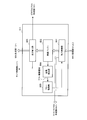
- FIG. 2 is a block diagram showing a configuration of communication apparatus 100 according to Embodiment 1 of the present invention.
- the communication apparatus 100 includes a MAC processing unit 101, an RLC processing unit 102, and a PDCP processing unit 103. Further, the communication device 100 can be applied to a wireless terminal device or a wireless base station device.
- the MAC processing unit 101 as a receiving unit performs MAC layer processing on received data received from a communication partner (not shown) and outputs the data to the RLC processing unit 102. Further, the MAC processing unit 101 performs MAC layer processing on the transmission data input from the RLC processing unit 102 and transmits the data to the communication partner. Received data is composed of a plurality of data units. Therefore, the MAC processing unit 101 receives data units.
- the RLC processing unit 102 performs RLC layer processing on the received data input from the MAC processing unit 101 and outputs the data to the PDCP processing unit 103.
- the RLC processing unit 102 performs retransmission control of the missing reception data.
- the RLC processing unit 102 can identify each data unit by SN, retransmission control is performed in units of data units.
- the RLC processing unit 102 performs RLC processing on the transmission data input from the PDCP processing unit 103 and outputs the transmission data to the MAC processing unit 101.
- the PDCP processing unit 103 performs PDCP layer processing on the reception data input from the RLC processing unit 102 and outputs the result as reception data.
- the PDCP processing unit 103 performs PDCP layer processing on the input transmission data and outputs the result to the RLC processing unit 102.
- the defect detection unit 111 constitutes detection means.
- the timer control unit 113 constitutes setting means.
- the STATUS PDU creation unit 114 and the data creation unit 115 constitute a retransmission request unit.
- the missing detection unit 111 stores the reception data input from the MAC processing unit 101 in the reception buffer. Further, the missing detection unit 111 performs a rearrangement process on the received data stored in the reception buffer, and detects missing data that is missing from the received data. In addition, when the missing data is not detected, the missing data detector 111 outputs the rearranged received data to the SDU generator 112. In addition, when detecting missing data, the missing detection unit 111 notifies the timer control unit 113 of a missing state of received data each time detection is performed. In addition, when detecting missing data, the missing detection unit 111 notifies the STATUS PDU creation unit 114 of the SN of the missing data every time it is detected.
- the SDU generation unit 112 generates an SDU (service data unit) from the rearranged received data input from the defect detection unit 111 and outputs it to the PDCP processing unit 103.
- the timer control unit 113 manages the timer and sets a monitoring time for monitoring the reception of the missing data every time a missing situation is input from the missing detection unit 111. Also, the timer control unit 113 outputs a STATUS PDU creation trigger to the STATUS PDU creation unit 114 when the monitoring time measured by the timer has expired. Details of the configuration of the timer control unit 113 will be described later.
- the STATUS PDU creation unit 114 creates a STATUS PDU including a single SN input from the defect detection unit 111 when a trigger is input from the timer control unit 113. Also, the STATUS PDU creation unit 114 outputs the created STATUS PDU to the data creation unit 115.
- the data creation unit 115 uses the transmission data input from the PDCP processing unit 103 or the STATUS PDU input from the STATUS PDU creation unit 114 to generate transmission data. Further, the data creation unit 115 outputs the created transmission data to the MAC processing unit 101.
- FIG. 3 is a block diagram showing the configuration of the timer control unit 113.
- a plurality of timer units 201 are provided, measure the time according to the measurement start instruction from the timer management unit 202, and notify the timer management unit 202 when the measurement is completed.
- the timer management unit 202 selects a single or a plurality of timer units 201 according to the defect status input from the defect detection unit 111, and instructs the selected timer unit 201 to start measurement.
- the timer management unit 202 receives a notification from the timer unit 201 that the measurement time has expired, the timer management unit 202 instructs the trigger generation unit 203 to generate a trigger.
- the trigger generation unit 203 When receiving the trigger generation instruction from the timer management unit 202, the trigger generation unit 203 generates a STATUS PDU creation trigger and outputs the generated trigger to the STATUS PDU creation unit 114.
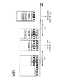
- FIG. 4 is a diagram illustrating a data retransmission method in the communication apparatus 100.
- the monitoring time # 401 and the monitoring time # 402 are each set to wait for the completion of retransmission in the MAC layer, and are set to a value obtained by multiplying the HARQ RTT and the maximum number of retransmissions, for example.
- the data rearrangement waiting time can be shortened, so that the amount of data to be stored on the receiving side can be reduced, and the capacity of the RLC layer buffer can be reduced. be able to.
- low-delay data transmission is realized only in the communication device 100.
- the present invention is not limited to this, and the present invention is also applicable to low-delay data transmission in the communication partner in addition to the communication device 100. be able to. As a result, the time until the STATUS Report is returned is shortened, so that the capacity of the buffer on the opposite side can also be reduced.
- FIG. 5 is a block diagram showing a configuration of communication apparatus 500 according to Embodiment 2 of the present invention.
- a communication device 500 shown in FIG. 5 has a defect detection unit 511 instead of the defect detection unit 111 and timer control instead of the timer control unit 113, compared to the communication device 100 according to the first embodiment shown in FIG. Part 512.
- FIG. 5 parts having the same configuration as in FIG.
- the communication apparatus 500 includes a MAC processing unit 101, a PDCP processing unit 103, and an RLC processing unit 501. Further, the communication device 500 can be applied to a wireless terminal device or a wireless base station device.
- the MAC processing unit 101 performs MAC layer processing on received data received from a communication partner (not shown) and outputs the data to the RLC processing unit 501. Further, the MAC processing unit 101 performs MAC layer processing on the transmission data input from the RLC processing unit 501, and transmits the data to the communication partner. Received data is composed of a plurality of data units. Therefore, the MAC processing unit 101 receives data units.
- the RLC processing unit 501 performs RLC layer processing on the received data input from the MAC processing unit 101 and outputs the result to the PDCP processing unit 103.
- the RLC processing unit 501 performs retransmission control of the missing reception data.
- the RLC processing unit 501 can identify each data unit by SN, it performs retransmission control in units of data units.
- the RLC processing unit 501 performs RLC processing on the transmission data input from the PDCP processing unit 103 and outputs the transmission data to the MAC processing unit 101.
- the PDCP processing unit 103 performs PDCP layer processing on the reception data input from the RLC processing unit 501 and outputs the result as reception data. Further, PDCP processing section 103 performs PDCP layer processing on the input transmission data and outputs the result to RLC processing section 501.
- the missing detection unit 511 stores the reception data input from the MAC processing unit 101 in the reception buffer.
- the missing detection unit 511 performs a rearrangement process on the received data stored in the reception buffer, and detects missing data that is missing from the received data.
- the missing detection unit 511 outputs the rearranged received data to the SDU generation unit 112.
- the loss detection unit 511 instructs the timer control unit 512 to measure time when the loss data is detected.
- the missing data detection unit 511 notifies the STATUS PDU creation unit 114 of the SN of the missing data or receives the received data input from the MAC processing unit 101 according to the free area of the reception buffer. Discard data and perform flow control. Details of the configuration of the defect detection unit 511 will be described later.
- the SDU generation unit 112 generates an SDU (service data unit) from the rearranged received data input from the defect detection unit 511 and outputs the SDU to the PDCP processing unit 103.
- the timer control unit 512 measures time according to the time measurement instruction from the defect detection unit 511. Also, the timer control unit 512 outputs a STATUS PDU creation trigger to the STATUS PDU creation unit 114 when the time measurement by the timer has expired.
- the STATUS PDU creation unit 114 creates a STATUS PDU including the SN input from the defect detection unit 511 when a trigger is input from the timer control unit 512. Also, the STATUS PDU creation unit 114 outputs the created STATUS PDU to the data creation unit 115.
- FIG. 6 is a block diagram illustrating a configuration of the defect detection unit 511.
- the reception control unit 601 stores the reception data input from the MAC processing unit 101 in the reception buffer 602. In addition, when receiving a reception control notification from the flow control unit 605, the reception control unit 601 determines whether or not the RLC processing unit 501 processes the reception data input from the MAC processing unit 101. In addition, when it is determined that the RLC processing unit 501 performs processing, the reception control unit 601 outputs the received data SN input from the MAC processing unit 101 to the STATUS PDU creation unit 114. In addition, when it is determined that the RLC processing unit 501 does not process the reception control unit 601, the reception data input from the MAC processing unit 101 is discarded. Note that a method for determining whether or not to perform processing in the RLC processing unit 501 will be described later.
- the reception buffer 602 stores the reception data input from the reception control unit 601 for rearrangement processing.
- the rearrangement unit 603 extracts the received data stored in the reception buffer 602 from the reception buffer 602 and performs a rearrangement process. Further, rearrangement section 603 detects the presence or absence of missing data in the rearranged received data. Further, the rearrangement unit 603 outputs the rearranged reception data to the SDU generation unit 112 when it detects that there is no loss of reception data. In addition, when the rearrangement unit 603 detects that there is a loss of received data, the rearrangement unit 603 notifies the STATUS PDU creation unit 114 of the missing single SN and instructs the timer control unit 512 to start time measurement. .
- the depletion detection unit 604 notifies the flow control unit 605 of a flow control notification when detecting that the free area of the reception buffer 602 has become equal to or less than the threshold value.
- the flow control unit 605 When the flow control unit 605 receives a flow control notification from the depletion detection unit 604, the flow control unit 605 notifies the reception control unit 601 of an acceptance control notification.
- FIG. 7 is a diagram illustrating a data retransmission method in the communication apparatus 500.
- the flow control unit 605 of the loss detection unit 511 sends a flow control notification for flow control to the reception control unit 601 of the loss detection unit 511 when the amount of data stored in the reception buffer 602 exceeds a threshold value.
- the monitoring time # 701 and the monitoring time # 702 are each set to wait for the completion of retransmission in the MAC layer, and are set to a value obtained by multiplying the HARQ RTT and the maximum number of retransmissions, for example.
- the reception control unit 601 may determine that all the reception data waiting for retransmission is processed in the RLC processing unit 501, or only the oldest reception data waiting for retransmission is RLC processed. It may be determined that processing is performed in the unit 501. In addition, when receiving the flow control notification, the reception control unit 601 may determine that only the received control data (STATUS PDU) is processed in the RLC processing unit 501. At this time, the communication apparatus 500 may retransmit data to the communication partner.
- STATUS PDU received control data
- reception buffer when the reception buffer is exhausted, only reception data waiting for retransmission is accepted.
- low-delay data transmission can be performed even when the memory size is suppressed, and repetition of retransmission can be prevented, and throughput can be improved.
- the low-delay data transmission function is installed only in the communication device 500.
- the present invention is not limited to this, and the low-latency data transmission function is installed in the communication partner in addition to the communication device 500. can do. As a result, the time until the STATUS Report is returned can be shortened, and the buffer capacity of the communication partner can also be reduced.
- the RLC processing unit detects the reception buffer depletion and performs flow control.
- the present invention is not limited to this, and flow control notification may be received from an upper layer. .
- the communication apparatus and the data retransmission method according to the present invention are suitable for performing processing in the layer 2 of a communication system such as LTE (Long Term Evolution).
- LTE Long Term Evolution
Landscapes
- Engineering & Computer Science (AREA)
- Computer Networks & Wireless Communication (AREA)
- Signal Processing (AREA)
- Detection And Prevention Of Errors In Transmission (AREA)
- Mobile Radio Communication Systems (AREA)
- Communication Control (AREA)
Abstract
メモリサイズを抑制しても低遅延のデータ伝送を行うことができるとともに再送の繰り返しを防ぐことができる通信装置。この装置では、MAC処理部(101)は、複数のデータユニットから構成される受信データを受信する。欠損検出部(111)は、MAC処理部(101)から入力した受信データのうちで欠損している欠損データを検出する。タイマ制御部(113)は、欠損検出部(111)により複数の欠損データを検出した場合に、検出の都度、所定の監視時間を設定する。STATUS PDU作成部(114)は、タイマ制御部(113)により設定した各々の監視時間内に欠損データを受信しない場合に、欠損データの再送を要求するために欠損データのSNを含むSTATUS PDUを作成する。
Description
本発明は、通信装置及びデータ再送方法に関し、例えばLTE(Long Term Evolution)等の通信システムのレイヤ2における処理を行う通信装置及びそのデータ再送方法に関する。
移動体通信システムのアクセス方式としてLTEシステムが標準化されている。このシステムでは、メモリサイズを削減するために、レイヤ2の処理におけるMACサブレイヤの機能とRLCサブレイヤの機能とを一部統合している。即ち、LTEシステムでは、MACレイヤのデータ再送機能(HARQ:Hybrid ARQ)におけるデータの並べ替え処理(Reordering処理)と、RLCレイヤのデータ再送機能におけるデータの並べ替え処理とを統合している(例えば、非特許文献1)。これにより、LTEシステムでは、データの並べ替え処理は、MACレイヤで行わず、RLCレイヤにおいて行う。
具体的には、MACレイヤでは、受信データをHARQ合成した後、CRC(Cyclic Redundancy Check)でOKとなったデータをRLCレイヤに渡す。RLCレイヤでは、ヘッダに付加されたSN(Sequence Number)に従い、受信ウィンドウの制御を行う。この時、RLCレイヤでは、データの欠損が見つかった場合は、通信相手のRLCレイヤに向けて再送の要求を行う。
ただし、RLCレイヤは、MACレイヤの並び替え処理と同等の機能を有するため、直ちに再送要求を行わずに、MACレイヤでの再送の完了を待って再送要求を行う。即ち、RLCレイヤでは、タイマ(t-Reorderingタイマ)で計測する所定の時間が経過した後に、欠損したSNを通信相手のRLCレイヤに通知する。
3GPPスペックに基づいた、従来のRLCレイヤでデータの欠損を検出した場合の再送制御について、図1を用いて詳細に説明する。図1は、従来のRLCレイヤでデータの欠損を検出した場合のデータ再送方法を示す図である。
図1より、従来の再送制御では、RLCレイヤでSN=1のデータを受信した際に、SN=0のデータが欠損したことを検出し、タイマ(t-Reorderingタイマ)を起動する。このタイマで計測する監視時間T1が満了するまでに、SN=0のデータを受信しない場合には、STATUS PDUに「NACK SN=0」という情報を入れて、対向RLCに送信する。ここで、監視時間T1は、MACレイヤにおける再送の完了を待つために設定されるものであるため、HARQのRTTと最大再送回数とを乗算した値以上に設定される。
また、従来は、タイマの起動中に、複数のデータの欠損があった場合(図1では、SN=0及びSN=2)、1つ目の欠損データ(SN=0)検出時に計測を開始した監視時間#10が満了した後に、2つ目の欠損データ(SN=2)についての計測を開始する。従って、従来は、受信タイミングが近い複数のデータに欠損が生じた場合、1つ目の欠損データ検出時に計測を開始した監視時間#10が満了し、かつその後計測を開始した監視時間#11が満了するまで、2つ目以降の欠損データの再送を要求しない。
3GPP TS36.322 V8.8.0 (2010-08)
しかしながら、従来の再送制御においては、受信タイミングが近い複数のデータに欠損が生じた場合には再送が遅れるので、受信データの遅延量が増大するという問題がある。また、バッファ内のデータ量が所定値を超えた場合に廃棄する方法を採用する場合には、遅延量の増大に伴って廃棄されるデータが増大する。この結果、廃棄されたデータは再送されるので、受信データの遅延量が更に増大するという問題がある。また、バッファ内のデータ量が所定値を超えた場合に廃棄する方法を採用する場合には、再送されてくるデータも廃棄されるため、データの並び替えの際にデータの順序が整わない。この結果、再送が繰り返され、通信相手において再送回数が上限値に達することにより、RRC接続が再接続となり、復旧に時間を要するという問題がある。
本発明の目的は、メモリサイズを抑制しても低遅延のデータ伝送を行うことができるとともに再送の繰り返しを防ぐことができる通信装置及びデータ再送方法を提供することを目的とする。
本発明の通信装置は、複数のデータユニットを順次受信する受信手段と、前記受信手段により受信した前記データユニットのうちで欠損している欠損データを検出する検出手段と、前記検出手段により複数の前記欠損データを検出した場合に、前記検出の都度所定の監視時間を設定する設定手段と、前記設定手段により設定した各々の前記監視時間内に前記欠損データを受信しない場合に、前記欠損データの再送を各々の前記監視時間経過後に順次要求する再送要求手段と、を具備する構成を採る。
本発明のデータ再送方法は、通信装置におけるデータ再送方法であって、複数のデータユニットを順次受信する受信ステップと、前記受信ステップにより受信した前記データユニットのうちで欠損している欠損データを検出する検出ステップと、前記検出ステップにより複数の前記欠損データを検出した場合に、前記検出の都度所定の監視時間を設定する設定ステップと、前記設定ステップにより設定した各々の前記監視時間内に前記欠損データを受信しない場合に、前記欠損データの再送を各々の前記監視時間経過後に順次要求する再送要求ステップと、を具備するようにした。
本発明によれば、メモリサイズを抑制しても低遅延のデータ伝送を行うことができるとともに再送の繰り返しを防ぐことができる。
以下、本発明の実施の形態について、図面を参照して詳細に説明する。
(実施の形態1)
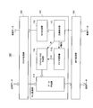
図2は、本発明の実施の形態1に係る通信装置100の構成を示すブロック図である。
図2は、本発明の実施の形態1に係る通信装置100の構成を示すブロック図である。
通信装置100は、MAC処理部101と、RLC処理部102と、PDCP処理部103とを有する。また、通信装置100は、無線端末装置または無線基地局装置に適用することができる。
受信手段としてのMAC処理部101は、図示しない通信相手から受信した受信データに対してMACレイヤ処理を施してRLC処理部102へ出力する。また、MAC処理部101は、RLC処理部102から入力した送信データに対してMACレイヤ処理を施して通信相手に送信する。受信データは、複数のデータユニットから構成されている。従って、MAC処理部101は、データユニット単位で受信する。
RLC処理部102は、MAC処理部101から入力した受信データに対してRLCレイヤ処理を施してPDCP処理部103へ出力する。また、RLC処理部102は、MAC処理部101から入力した受信データに欠損が生じている場合には、欠損した受信データの再送制御を行う。この際、RLC処理部102は、各データユニットをSNにより識別することができるので、データユニット単位で再送制御を行う。また、RLC処理部102は、PDCP処理部103から入力した送信データに対してRLC処理を施してMAC処理部101へ出力する。
PDCP処理部103は、RLC処理部102から入力した受信データに対してPDCPレイヤ処理を施して受信データとして出力する。また、PDCP処理部103は、入力した送信データに対してPDCPレイヤ処理を施してRLC処理部102へ出力する。
次に、RLC処理部102の構成の詳細について、図2を用いて説明する。
図2において、欠損検出部111は検出手段を構成する。また、タイマ制御部113は設定手段を構成する。また、STATUS PDU作成部114及びデータ作成部115は再送要求手段を構成する。
欠損検出部111は、MAC処理部101から入力した受信データを受信バッファに格納する。また、欠損検出部111は、受信バッファに格納した受信データの並べ替え処理を行い、受信データのうちで欠損している欠損データを検出する。また、欠損検出部111は、欠損データを検出しない場合には、並び替え処理した受信データをSDU生成部112へ出力する。また、欠損検出部111は、欠損データを検出した場合には、検出の都度、受信データの欠損状況をタイマ制御部113へ通知する。また、欠損検出部111は、欠損データを検出した場合には、検出の都度、欠損データのSNをSTATUS PDU作成部114へ通知する。
SDU生成部112は、欠損検出部111から入力した並び替え後の受信データよりSDU(サービスデータユニット)を生成してPDCP処理部103へ出力する。
タイマ制御部113は、欠損検出部111から欠損状況が入力する都度、タイマを管理して、欠損データの受信を監視する監視時間を設定する。また、タイマ制御部113は、タイマにより計測する監視時間が満了した場合に、STATUS PDU作成のトリガをSTATUS PDU作成部114へ出力する。なお、タイマ制御部113の構成の詳細については後述する。
STATUS PDU作成部114は、タイマ制御部113よりトリガが入力した場合に、欠損検出部111から入力した単一のSNを含むSTATUS PDUを作成する。また、STATUS PDU作成部114は、作成したSTATUS PDUをデータ作成部115へ出力する。
データ作成部115は、PDCP処理部103から入力した送信データ、またはSTATUS PDU作成部114から入力したSTATUS PDUを用いて、送信データを生成する。また、データ作成部115は、作成した送信データをMAC処理部101へ出力する。
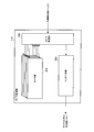
次に、タイマ制御部113の構成について、図3を用いて説明する。図3は、タイマ制御部113の構成を示すブロック図である。
タイマ部201は、複数設けられ、タイマ管理部202からの計測開始の指示に従って時間を計測し、計測満了の際にその旨をタイマ管理部202へ通知する。
タイマ管理部202は、欠損検出部111から入力した欠損状況に応じて、単一または複数のタイマ部201を選択し、選択したタイマ部201に計測開始を指示する。また、タイマ管理部202は、タイマ部201から計測時間が満了した旨の通知を受けた際に、トリガ生成部203に対してトリガの生成を指示する。
トリガ生成部203は、タイマ管理部202からトリガ生成の指示を受けた際に、STATUS PDU作成のトリガを生成し、生成したトリガをSTATUS PDU作成部114へ出力する。
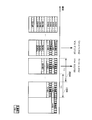
次に、通信装置100におけるデータ再送方法について、図4を用いて説明する。図4は、通信装置100におけるデータ再送方法を示す図である。
通信装置100の欠損検出部111は、SN=1のデータを取得し、SN=0のデータが欠損したことを検出する。これにより、タイマ制御部113は、タイマ部201のタイマ#1を選択して起動する。その後、通信装置100の欠損検出部111は、SN=3のデータを取得し、SN=2のデータが欠損したことを検出する。これにより、タイマ制御部113は、タイマ部201のタイマ#1とは異なるタイマ#2を選択し、タイマ#1の計測満了を待たずにタイマ#2を起動する。即ち、タイマ制御部113は、複数のタイマを同時に起動する。STATUS PDU作成部114は、タイマ#1により計測する監視時間#401が満了した場合、SN=0の欠損を通信相手に通知するために、SN=0を含むSTATUS PDUを作成する。そして、通信装置100は、作成したSTATUS PDUを通信相手に送信する。その後、STATUS PDU作成部114は、タイマ#2により計測する監視時間#402が満了した場合、SN=2の欠損を通信相手に通知するために、SN=2を含むSTATUS PDUを作成する。そして、通信装置100は、作成したSTATUS PDUを通信相手に送信する。なお、監視時間#401及び監視時間#402は、MACレイヤにおける再送の完了を待つために各々設定されるものであり、例えば、HARQのRTTと最大再送回数とを乗算した値に設定される。
このように、本実施の形態では、RLCレイヤにおいて欠損したデータの再送を直ちに通信相手に要求することができる。これにより、本実施の形態によれば、メモリサイズを抑制しても低遅延のデータ伝送を行うことができるとともに再送の繰り返しを防ぐことができ、スループットを向上させることができる。
また、本実施の形態によれば、データの並び替えの待ち時間を短縮することができるので、受信側に溜めておくべきデータ量を削減することができ、RLCレイヤのバッファの容量を削減することができる。
なお、本実施の形態において、通信装置100においてのみ低遅延のデータ伝送を実現したが、本発明はこれに限らず、通信装置100に加えて通信相手においても低遅延のデータ伝送にも適用することができる。これにより、STATUS Reportが返送されるまでの時間が短縮されることにより、対向側のバッファの容量も削減することができる。
(実施の形態2)
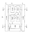
図5は、本発明の実施の形態2に係る通信装置500の構成を示すブロック図である。
図5は、本発明の実施の形態2に係る通信装置500の構成を示すブロック図である。
図5に示す通信装置500は、図2に示す実施の形態1に係る通信装置100に対して、欠損検出部111の代わりに欠損検出部511を有し、タイマ制御部113の代わりにタイマ制御部512を有する。なお、図5において、図2と同一構成である部分には同一の符号を付してその説明を省略する。
通信装置500は、MAC処理部101と、PDCP処理部103と、RLC処理部501とを有する。また、通信装置500は、無線端末装置または無線基地局装置に適用することができる。
MAC処理部101は、図示しない通信相手から受信した受信データに対してMACレイヤ処理を施してRLC処理部501へ出力する。また、MAC処理部101は、RLC処理部501から入力した送信データに対してMACレイヤ処理を施して通信相手に送信する。受信データは、複数のデータユニットから構成されている。従って、MAC処理部101は、データユニット単位で受信する。
RLC処理部501は、MAC処理部101から入力した受信データに対してRLCレイヤ処理を施してPDCP処理部103へ出力する。また、RLC処理部501は、MAC処理部101から入力した受信データに欠損が生じている場合には、欠損した受信データの再送制御を行う。この際、RLC処理部501は、各データユニットをSNにより識別することができるので、データユニット単位で再送制御を行う。また、RLC処理部501は、PDCP処理部103から入力した送信データに対してRLC処理を施してMAC処理部101へ出力する。
PDCP処理部103は、RLC処理部501から入力した受信データに対してPDCPレイヤ処理を施して受信データとして出力する。また、PDCP処理部103は、入力した送信データに対してPDCPレイヤ処理を施してRLC処理部501へ出力する。
次に、RLC処理部501の構成の詳細について、図5を用いて説明する。
欠損検出部511は、MAC処理部101から入力した受信データを受信バッファに格納する。また、欠損検出部511は、受信バッファに格納した受信データの並べ替え処理を行い、受信データのうちで欠損している欠損データを検出する。また、欠損検出部511は、欠損データを検出しない場合には、並び替え処理した受信データをSDU生成部112へ出力する。また、欠損検出部511は、欠損データを検出した場合には、タイマ制御部512に対して時間の計測を指示する。また、欠損検出部511は、欠損データを検出した場合には、受信バッファの空き領域に応じて、欠損データのSNをSTATUS PDU作成部114へ通知するか、またはMAC処理部101から入力した受信データを廃棄してフロー制御を行う。なお、欠損検出部511の構成の詳細については後述する。
SDU生成部112は、欠損検出部511から入力した並び替え後の受信データよりSDU(サービスデータユニット)を生成してPDCP処理部103へ出力する。
タイマ制御部512は、欠損検出部511からの時間の計測の指示に従って時間を計測する。また、タイマ制御部512は、タイマでの時間の計測が満了した場合に、STATUS PDU作成のトリガをSTATUS PDU作成部114へ出力する。
STATUS PDU作成部114は、タイマ制御部512よりトリガが入力した場合に、欠損検出部511から入力したSNを含むSTATUS PDUを作成する。また、STATUS PDU作成部114は、作成したSTATUS PDUをデータ作成部115へ出力する。
次に、欠損検出部511の構成について、図6を用いて説明する。図6は、欠損検出部511の構成を示すブロック図である。
受入制御部601は、フロー制御部605から受入制御通知を受けない場合には、MAC処理部101から入力した受信データを受信バッファ602に格納する。また、受入制御部601は、フロー制御部605から受入制御通知を受けた場合に、MAC処理部101から入力した受信データをRLC処理部501において処理するか否かを判定する。また、受入制御部601は、RLC処理部501において処理すると判定した場合には、MAC処理部101から入力した受信データのSNをSTATUS PDU作成部114へ出力する。また、受入制御部601は、RLC処理部501において処理しないと判定した場合には、MAC処理部101から入力した受信データを廃棄する。なお、RLC処理部501において処理するか否かの判定方法については後述する。
受信バッファ602は、受入制御部601から入力した受信データを並び替え処理のために格納する。
並び替え部603は、受信バッファ602に格納した受信データを受信バッファ602から取り出して並び替え処理を行う。また、並び替え部603は、並び替えた受信データにおける欠損の有無を検出する。また、並び替え部603は、受信データの欠損無しを検出した場合には、並び替えた受信データをSDU生成部112へ出力する。また、並び替え部603は、受信データの欠損有りを検出した場合には、欠損した単一のSNをSTATUS PDU作成部114へ通知するとともに、時間の計測の開始をタイマ制御部512に指示する。
枯渇検出部604は、受信バッファ602の空き領域が閾値以下になったことを検出した場合に、フロー制御通知をフロー制御部605に通知する。
フロー制御部605は、枯渇検出部604からフロー制御通知を受けた場合に、受入制御部601に対して受入制御通知を通知する。
次に、通信装置500におけるデータ再送方法について、図7を用いて説明する。図7は、通信装置500におけるデータ再送方法を示す図である。
通信装置500の欠損検出部511は、SN=1のデータを取得し、SN=0のデータが欠損したことを検出する。これにより、タイマ制御部512は、タイマを起動する。その後、通信装置500の欠損検出部511は、SN=3のデータを取得し、SN=2のデータが欠損したことを検出する。また、タイマ制御部512は、タイマにより計測する監視時間#701が満了した際に、トリガをSTATUS PDU作成部114へ出力する。これにより、STATUS PDU作成部114は、SN=0のデータの欠損を通信相手に通知するために、SN=0を含むSTATUS PDUを作成する。また、通信装置500は、作成したSTATUS PDUを通信相手に送信する。その後、タイマ制御部512は、SN=2のデータが欠損していることにより、再度タイマを起動する。また、タイマ制御部512は、タイマにより計測する監視時間#702が満了した際に、トリガをSTATUS PDU作成部114へ出力する。これにより、STATUS PDU作成部114は、SN=2のデータの欠損を通信相手に通知するために、SN=2を含むSTATUS PDUを作成する。また、通信装置500は、作成したSTATUS PDUを通信相手に送信する。その後も、SN=2のデータが再送されてくるまでは、新しいデータを受信する。
この際、欠損検出部511のフロー制御部605は、受信バッファ602に格納されるデータ量が閾値以上になった場合に、フロー制御するためのフロー制御通知を欠損検出部511の受入制御部601に通知する。これにより、受入制御部601は、受け入れた新しいデータをRLC処理部501において処理するか否かの判定を行う。即ち、受入制御部601は、再送を待っているSN=2以外の受信データについてはRLC処理部501において処理しないと判定する。この結果、受入制御部601は、SN=2以外の受信データの受け入れを停止し、取得した受信データの廃棄を開始する。一方、受入制御部601は、再送を待っているSN=2の受信データについてはRLC処理部501において処理すると判定する。この結果、受入制御部601は、SN=2の受信データを取得した場合は受信バッファ602へ出力する。従って、SN=2の受信データの欠損が無くなり、順序が揃うことで、上位レイヤに受信データを転送することができるようになる。また、これに伴って、欠損検出部511は、受信バッファ602を解放することができ、次の新たな受信データを取得できるようになる。なお、監視時間#701及び監視時間#702は、MACレイヤにおける再送の完了を待つために各々設定されるものであり、例えば、HARQのRTTと最大再送回数とを乗算した値に設定される。
ここで、受入制御部601は、フロー制御通知を受け取った場合に、再送待ちの受信データをすべてRLC処理部501において処理すると判定してもよいし、最も古い再送待ちの受信データのみをRLC処理部501において処理すると判定してもよい。また、受入制御部601は、フロー制御通知を受け取った場合に、受信した制御データ(STATUS PDU)のみをRLC処理部501において処理すると判定してもよい。また、この際に、通信装置500は、通信相手に対してデータの再送を行うようにしても良い。
このように、本実施の形態では、受信バッファが枯渇した場合に、再送待ちの受信データのみを受け入れる。これにより、本実施の形態によれば、メモリサイズを抑制しても低遅延のデータ伝送を行うことができるとともに再送の繰り返しを防ぐことができ、スループットを向上させることができる。
また、本実施の形態では、受信バッファが枯渇した場合に制御データのみを受け入れるようにし、上り回線と下り回線のいずれか一方がフロー制御状態にある場合でも、フロー制御状態に無い他方の回線における制御情報を受信する。これにより、本実施の形態によれば、フロー制御状態に無い回線の通信を継続することができる。
なお、本実施の形態において、通信装置500においてのみ低遅延のデータ伝送機能を搭載したが、本発明はこれに限らず、通信装置500に加えて通信相手にも低遅延のデータ伝送機能を搭載することができる。これにより、STATUS Reportが返送されるまでの時間を短縮することができ、通信相手のバッファ容量も削減することができる。
また、本実施の形態において、RLC処理部において受信バッファの枯渇を検出してフロー制御を行うようにしたが、本発明はこれに限らず、フロー制御通知を上位レイヤから受けるようにしてもよい。
2011年3月9日出願の特願2011-51609の日本出願に含まれる明細書、図面及び要約書の開示内容は、すべて本願に援用される。
本発明にかかる通信装置及びデータ再送方法は、例えばLTE(Long Term Evolution)等の通信システムのレイヤ2における処理を行うのに好適である。
100 通信装置
101 MAC処理部
102 RLC処理部
103 PDCP処理部
111 欠損検出部
112 SDU生成部
113 タイマ制御部
114 STATUS PDU作成部
115 データ作成部
101 MAC処理部
102 RLC処理部
103 PDCP処理部
111 欠損検出部
112 SDU生成部
113 タイマ制御部
114 STATUS PDU作成部
115 データ作成部
Claims (4)
- 複数のデータユニットを順次受信する受信手段と、
前記受信手段により受信した前記データユニットのうちで欠損している欠損データを検出する検出手段と、
前記検出手段により複数の前記欠損データを検出した場合に、前記検出の都度所定の監視時間を設定する設定手段と、
前記設定手段により設定した各々の前記監視時間内に前記欠損データを受信しない場合に、前記欠損データの再送を各々の前記監視時間経過後に順次要求する再送要求手段と、
を具備する通信装置。 - 請求項1記載の通信装置を具備する無線端末装置。
- 請求項1記載の通信装置を具備する無線基地局装置。
- 通信装置におけるデータ再送方法であって、
複数のデータユニットを順次受信する受信ステップと、
前記受信ステップにより受信した前記データユニットのうちで欠損している欠損データを検出する検出ステップと、
前記検出ステップにより複数の前記欠損データを検出した場合に、前記検出の都度所定の監視時間を設定する設定ステップと、
前記設定ステップにより設定した各々の前記監視時間内に前記欠損データを受信しない場合に、前記欠損データの再送を各々の前記監視時間経過後に順次要求する再送要求ステップと、
を具備するデータ再送方法。
Applications Claiming Priority (2)
| Application Number | Priority Date | Filing Date | Title |
|---|---|---|---|
| JP2011-051609 | 2011-03-09 | ||
| JP2011051609A JP2012191326A (ja) | 2011-03-09 | 2011-03-09 | 通信装置及びデータ再送方法 |
Publications (1)
| Publication Number | Publication Date |
|---|---|
| WO2012120832A1 true WO2012120832A1 (ja) | 2012-09-13 |
Family
ID=46797806
Family Applications (1)
| Application Number | Title | Priority Date | Filing Date |
|---|---|---|---|
| PCT/JP2012/001352 Ceased WO2012120832A1 (ja) | 2011-03-09 | 2012-02-28 | 通信装置及びデータ再送方法 |
Country Status (3)
| Country | Link |
|---|---|
| JP (1) | JP2012191326A (ja) |
| TW (1) | TW201247004A (ja) |
| WO (1) | WO2012120832A1 (ja) |
Cited By (1)
| Publication number | Priority date | Publication date | Assignee | Title |
|---|---|---|---|---|
| CN110235416A (zh) * | 2017-04-28 | 2019-09-13 | Oppo广东移动通信有限公司 | 无线通信的方法和装置 |
Families Citing this family (1)
| Publication number | Priority date | Publication date | Assignee | Title |
|---|---|---|---|---|
| JPWO2019167228A1 (ja) * | 2018-03-01 | 2021-03-04 | 三菱電機株式会社 | 移動通信システム、受信側装置および送信側装置 |
Citations (2)
| Publication number | Priority date | Publication date | Assignee | Title |
|---|---|---|---|---|
| JP2005529546A (ja) * | 2002-06-10 | 2005-09-29 | クゥアルコム・インコーポレイテッド | Cdma通信システムのためのrlp再送 |
| JP2010541310A (ja) * | 2007-09-25 | 2010-12-24 | ゼットティーイー コーポレーション | 自動再送要求状況報告のトリガ方法 |
-
2011
- 2011-03-09 JP JP2011051609A patent/JP2012191326A/ja not_active Withdrawn
-
2012
- 2012-02-28 WO PCT/JP2012/001352 patent/WO2012120832A1/ja not_active Ceased
- 2012-03-07 TW TW101107686A patent/TW201247004A/zh unknown
Patent Citations (2)
| Publication number | Priority date | Publication date | Assignee | Title |
|---|---|---|---|---|
| JP2005529546A (ja) * | 2002-06-10 | 2005-09-29 | クゥアルコム・インコーポレイテッド | Cdma通信システムのためのrlp再送 |
| JP2010541310A (ja) * | 2007-09-25 | 2010-12-24 | ゼットティーイー コーポレーション | 自動再送要求状況報告のトリガ方法 |
Cited By (2)
| Publication number | Priority date | Publication date | Assignee | Title |
|---|---|---|---|---|
| CN110235416A (zh) * | 2017-04-28 | 2019-09-13 | Oppo广东移动通信有限公司 | 无线通信的方法和装置 |
| CN110235416B (zh) * | 2017-04-28 | 2023-09-26 | Oppo广东移动通信有限公司 | 无线通信的方法和装置、计算机可读存储介质 |
Also Published As
| Publication number | Publication date |
|---|---|
| JP2012191326A (ja) | 2012-10-04 |
| TW201247004A (en) | 2012-11-16 |
Similar Documents
| Publication | Publication Date | Title |
|---|---|---|
| TWI471024B (zh) | 在基地台與行動台之間交換資料的方法與裝置 | |
| US8837411B2 (en) | Method and arrangement in a wireless communication system | |
| TWI400969B (zh) | 處理一傳輸時間間隔集束之重傳的方法及通訊裝置 | |
| DK2315383T3 (en) | Method and apparatus for submitting a status report | |
| US9059848B2 (en) | Method and arrangement in a wireless communication system | |
| AU2016364681B2 (en) | Predictive acknowledgment feedback mechanism | |
| CN107852768A (zh) | 用于增强型分量载波下的分组数据汇聚协议(pdcp)重排序的方法、装置和计算机可读介质 | |
| KR20100053625A (ko) | 무선 통신 시스템에서의 핸드오버 동안 데이터의 계층 2 터널링 | |
| CN108260222B (zh) | 一种上行资源调度的方法和装置 | |
| CN109586853B (zh) | 上行连续重复传输的终止方法、装置、基站及用户设备 | |
| CN110168983A (zh) | 用于数据重传的方法和设备 | |
| JP5120457B2 (ja) | 通信装置、通信方法、および通信プログラム | |
| JP2017011534A (ja) | 無線通信装置 | |
| WO2012120832A1 (ja) | 通信装置及びデータ再送方法 | |
| CN104349490A (zh) | 调度方法及装置 | |
| WO2007148630A1 (ja) | 移動通信システムで使用される無線通信装置及び方法 | |
| US10892857B2 (en) | HARQ transmission of transport blocks | |
| HK40009949B (en) | Methods and devices for data retransmission | |
| HK40009949A (en) | Methods and devices for data retransmission | |
| JP2018182360A (ja) | 端末装置、制御方法、及びプログラム | |
| HK1148625A (en) | Service data unit discard timers |
Legal Events
| Date | Code | Title | Description |
|---|---|---|---|
| 121 | Ep: the epo has been informed by wipo that ep was designated in this application |
Ref document number: 12755525 Country of ref document: EP Kind code of ref document: A1 |
|
| NENP | Non-entry into the national phase |
Ref country code: DE |
|
| 32PN | Ep: public notification in the ep bulletin as address of the adressee cannot be established |
Free format text: NOTING OF LOSS OF RIGHTS PURSUANT TO RULE 112(1) EPC (EPO FORM 1205N DATED 15/11/2013) |
|
| 122 | Ep: pct application non-entry in european phase |
Ref document number: 12755525 Country of ref document: EP Kind code of ref document: A1 |