WO2012120180A1 - Shock-absorbing coupling for floating structures - Google Patents
Shock-absorbing coupling for floating structures Download PDFInfo
- Publication number
- WO2012120180A1 WO2012120180A1 PCT/ES2012/070155 ES2012070155W WO2012120180A1 WO 2012120180 A1 WO2012120180 A1 WO 2012120180A1 ES 2012070155 W ES2012070155 W ES 2012070155W WO 2012120180 A1 WO2012120180 A1 WO 2012120180A1
- Authority
- WO
- WIPO (PCT)
- Prior art keywords
- members
- mounting bodies
- grip members
- tire
- facing
- Prior art date
Links
Images

Classifications
-
- A—HUMAN NECESSITIES
- A01—AGRICULTURE; FORESTRY; ANIMAL HUSBANDRY; HUNTING; TRAPPING; FISHING
- A01K—ANIMAL HUSBANDRY; CARE OF BIRDS, FISHES, INSECTS; FISHING; REARING OR BREEDING ANIMALS, NOT OTHERWISE PROVIDED FOR; NEW BREEDS OF ANIMALS
- A01K61/00—Culture of aquatic animals
-
- A—HUMAN NECESSITIES
- A01—AGRICULTURE; FORESTRY; ANIMAL HUSBANDRY; HUNTING; TRAPPING; FISHING
- A01K—ANIMAL HUSBANDRY; CARE OF BIRDS, FISHES, INSECTS; FISHING; REARING OR BREEDING ANIMALS, NOT OTHERWISE PROVIDED FOR; NEW BREEDS OF ANIMALS
- A01K61/00—Culture of aquatic animals
- A01K61/50—Culture of aquatic animals of shellfish
- A01K61/54—Culture of aquatic animals of shellfish of bivalves, e.g. oysters or mussels
-
- E—FIXED CONSTRUCTIONS
- E04—BUILDING
- E04B—GENERAL BUILDING CONSTRUCTIONS; WALLS, e.g. PARTITIONS; ROOFS; FLOORS; CEILINGS; INSULATION OR OTHER PROTECTION OF BUILDINGS
- E04B1/00—Constructions in general; Structures which are not restricted either to walls, e.g. partitions, or floors or ceilings or roofs
- E04B1/38—Connections for building structures in general
- E04B1/58—Connections for building structures in general of bar-shaped building elements
- E04B1/5825—Connections for building structures in general of bar-shaped building elements with a closed cross-section
- E04B1/5837—Connections for building structures in general of bar-shaped building elements with a closed cross-section of substantially circular form
- E04B1/585—Connections for building structures in general of bar-shaped building elements with a closed cross-section of substantially circular form with separate connection devices
-
- A—HUMAN NECESSITIES
- A01—AGRICULTURE; FORESTRY; ANIMAL HUSBANDRY; HUNTING; TRAPPING; FISHING
- A01K—ANIMAL HUSBANDRY; CARE OF BIRDS, FISHES, INSECTS; FISHING; REARING OR BREEDING ANIMALS, NOT OTHERWISE PROVIDED FOR; NEW BREEDS OF ANIMALS
- A01K61/00—Culture of aquatic animals
- A01K61/60—Floating cultivation devices, e.g. rafts or floating fish-farms
-
- B—PERFORMING OPERATIONS; TRANSPORTING
- B63—SHIPS OR OTHER WATERBORNE VESSELS; RELATED EQUIPMENT
- B63B—SHIPS OR OTHER WATERBORNE VESSELS; EQUIPMENT FOR SHIPPING
- B63B17/00—Vessels parts, details, or accessories, not otherwise provided for
- B63B17/0081—Vibration isolation or damping elements or arrangements, e.g. elastic support of deck-houses
-
- B—PERFORMING OPERATIONS; TRANSPORTING
- B63—SHIPS OR OTHER WATERBORNE VESSELS; RELATED EQUIPMENT
- B63B—SHIPS OR OTHER WATERBORNE VESSELS; EQUIPMENT FOR SHIPPING
- B63B3/00—Hulls characterised by their structure or component parts
- B63B3/02—Hulls assembled from prefabricated sub-units
- B63B3/08—Hulls assembled from prefabricated sub-units with detachably-connected sub-units
-
- B—PERFORMING OPERATIONS; TRANSPORTING
- B63—SHIPS OR OTHER WATERBORNE VESSELS; RELATED EQUIPMENT
- B63B—SHIPS OR OTHER WATERBORNE VESSELS; EQUIPMENT FOR SHIPPING
- B63B35/00—Vessels or similar floating structures specially adapted for specific purposes and not otherwise provided for
- B63B35/58—Rafts, i.e. free floating waterborne vessels, of shallow draft, with little or no freeboard, and having a platform or floor for supporting a user
- B63B35/613—Rafts, i.e. free floating waterborne vessels, of shallow draft, with little or no freeboard, and having a platform or floor for supporting a user with tubular shaped flotation members
-
- B—PERFORMING OPERATIONS; TRANSPORTING
- B63—SHIPS OR OTHER WATERBORNE VESSELS; RELATED EQUIPMENT
- B63B—SHIPS OR OTHER WATERBORNE VESSELS; EQUIPMENT FOR SHIPPING
- B63B2221/00—Methods and means for joining members or elements
- B63B2221/20—Joining substantially rigid elements together by means that allow one or more degrees of freedom, e.g. hinges, articulations, pivots, universal joints, telescoping joints, elastic expansion joints, not otherwise provided for in this class
-
- Y—GENERAL TAGGING OF NEW TECHNOLOGICAL DEVELOPMENTS; GENERAL TAGGING OF CROSS-SECTIONAL TECHNOLOGIES SPANNING OVER SEVERAL SECTIONS OF THE IPC; TECHNICAL SUBJECTS COVERED BY FORMER USPC CROSS-REFERENCE ART COLLECTIONS [XRACs] AND DIGESTS
- Y02—TECHNOLOGIES OR APPLICATIONS FOR MITIGATION OR ADAPTATION AGAINST CLIMATE CHANGE
- Y02A—TECHNOLOGIES FOR ADAPTATION TO CLIMATE CHANGE
- Y02A40/00—Adaptation technologies in agriculture, forestry, livestock or agroalimentary production
- Y02A40/80—Adaptation technologies in agriculture, forestry, livestock or agroalimentary production in fisheries management
- Y02A40/81—Aquaculture, e.g. of fish
-
- Y—GENERAL TAGGING OF NEW TECHNOLOGICAL DEVELOPMENTS; GENERAL TAGGING OF CROSS-SECTIONAL TECHNOLOGIES SPANNING OVER SEVERAL SECTIONS OF THE IPC; TECHNICAL SUBJECTS COVERED BY FORMER USPC CROSS-REFERENCE ART COLLECTIONS [XRACs] AND DIGESTS
- Y10—TECHNICAL SUBJECTS COVERED BY FORMER USPC
- Y10T—TECHNICAL SUBJECTS COVERED BY FORMER US CLASSIFICATION
- Y10T403/00—Joints and connections
- Y10T403/45—Flexibly connected rigid members
Definitions
- the invention relates to a damping coupling for floating structures, and is especially intended, although not exclusively, for use in the coupling between modular structures for the formation of swamps and other support platforms and more particularly provided in the trays applied to the crop. of lamelibranch mollusks, in shallow waters or in the open sea. It could also be used in submerged or submersible structures.
- Document WO8703170 although not intended for shellfish farming, discloses a floating device for the breeding of fish and the like that incorporates at least one breeding bag carried by a cage equipped with floating bodies, the cage consisting of a three-dimensional shell composed of several bars arranged in polygons, the bars being elastically interconnected and interconnecting braces provided between at least some of the joints.
- EP0358421 discloses the use of a flexible coupling to join the frames in a fence structure for fish farming, the coupling includes first and second mounting means for incorporation into respective adjacent frames in the structure and a flexible body between said First and second mounting means.
- the rotational and translational movement between adjacent frames is determined by the flexible body material and by two mechanical stops.
- the coupling includes a mechanical connection between the mounting means in the event that the flexible body fails.
- An object of the invention is to provide a damping coupling for use in floating passing or loading structures and for use in structures intended for shellfish farming if so required.
- the coupling constructed in such a way that its use provides greater stability in all structures and better navigability in those planned for breeding, increasing its adaptability on the surface or submerged to shallow currents or angry raging of the waters, in order to achieve greater productivity, reducing or eliminating the landslides caused by the movement of the waters.
- shock absorber coupling for floating structures is intended for a simple and light construction, although strong and elastic to absorb the loads applied to storms and sea currents without structural deformations.
- a damping coupling for floating structures constructed with two mounting bodies adapted for their respective incorporation into contiguous elements of a structure and, among them, a number of tire covers which, in use, are kept horizontal.
- the number of couplings to be incorporated into a structure is variable.
- At each coupling there are at least one pair of mounting bodies facing each other, preferably two pairs, and between each pair there is a tire cover or other similar flexible body.
- a simplified expression of a mounting body has a support wall that can be conventionally connected by one of its faces to an element of the structure so that it faces another support wall connected in the same way to an adjacent element of the structure .
- the faces of the bearing walls not connected to the elements of the structure ensure the support of the grip members of the tire covers.
- the damping coupling is provided with first and second gripping members connected and respectively facing the same level in each of said mounting bodies, such that, between the first and second gripping members connected to one of the bodies of facing mounting and the first and second grip members respectively mounted on the facing mounting body is arranged the tire cover so that it is retained between them in diametrically opposite regions thereof so that the tire covers in the damping coupling and, therefore, in the structure, they can flex, stretch or twist freely over their central region by absorbing the movement of waves and sea currents.
- the first grip members are preferred by welding connected to the respective mounting bodies, while the second grip members are preferred connected, by conventional joining elements, sliding in vertically elongated holes provided in each of said mounting bodies, arranged above and in overlapping correspondence on the first grip members, so as to enable the relative approach and separation of the second grip members over the first in order to ensure the best retention of the tire covers.
- said first and second grip members are preferred constituted by steel plates formed with a retaining wall at their leading edge, which is directed in vertically opposite directions on both members to end in a respective horizontal retention wing turned towards inside. In this way, being between the walls and the retention wings of both members of grip the proximal region of the inner periphery of the immediate cover to the heel, the unwanted exit of the cover is avoided.
- the plate constituting the first grip member incorporates lower ribs that facilitate its welded connection to the support wall in the mounting body.
- the second grip member is provided with a fixing wall provided with holes, corresponding to the elongated holes provided in the support wall of the mounting body, for the passage of the connecting elements.
- At least one of both, first or second grip members provides for a continuous or not contour retaining wall adapted to the outer periphery of the tire cover.
- each tire cover be present, between said first and second gripping means connected to each mounting body, by means of threaded bars through the holes respectively provided. faced in one and in others, securing the bars by means of nuts applied on the outside of the grip members.
- Figure 1 shows, in perspective, the damping coupling for floating structures with all their components.
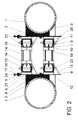
- Figure 2 shows, transversely sectioned, to the damping coupling for floating structures mounted with all its members.
- a damping coupling for floating structures is provided, particularized in this embodiment as a link between the modular frameworks that constitute them to form structures for shellfish farming, and in which each of The two mounting bodies (2), which can be incorporated into the structure, are formed with a curved wall (3) adapting to the curved surface of the hollow components (1) of two facing frames in the structure of floating trays that can be submerged and a flat support wall (4) provided with holes (5), which are observed vertically elongated and arranged on two levels thereof. Ribs (6) hold together both walls (3) and (4).
- the first gripping member (7) is formed with a plate with holes (8) of a general trapecial shape in plan, with its major side defined by a straight edge (9) adapted to the flat wall of lift (4), the contour of its minor side being curved-concave and extended vertically upwards forming a retaining wall (10) that can be seen topped by a horizontal retention wing (11) turned towards the inside of the plate (8 ), both (10) and (11) provided for the grip of a heel region of the tire (14) with the collaboration, in the example, of a retaining wall (12).
- Lowerly said first grip member (7) is observed with lower ribs (13) suitable to collaborate in its connection to the respective mounting bodies (2).
- the second grip member (15) is formed by a plate with holes (16) with a fixing wall (17), also provided with holes (18), which extends vertically upwards at one edge of the plate (16) and with a retaining wall (19) that extends vertically downwards at the opposite edge of the plate (16), with its contour adapted to the inner periphery of the tire cover (14 ), ending in a horizontal retention wing (20) turned inwards.
- threaded bars (22) cross the plates with holes (8, 16), once the tire covers (14) have been interposed between the first (7) and second (15) members of grip, being secured by nuts (23).
- Protective profiles (24) can be used to protect the living edges of the members in the shock absorber coupling.
- the tire covers (14) are stretched elastically forced by the greater separation of the walls (10) and (19) from the mounting bodies (2).
- the adaptations to the swings of the water will be absorbed by the flexion of the tire cover (14) ordered by the different inclination between the mounting bodies and therefore of the grip members (7) and (15) respectively fixed facing each other in the mounting bodies (2).
Abstract
Description
Claims (4)
- ACOPLAMIENTO AMORTIGUADOR PARA ESTRUCTURAS FLOTANTES, que incluye dos cuerpos de montaje (2) para ser respectivamente montados en componentes enfrentados (1) de armazones contiguos de una estructura, y al menos un cuerpo flexible tal como una cubierta de neumático (14) entre dichos cuerpos de montaje (2), caracterizado porque comprende primeros miembros de agarre (7) respectivamente conectados, enfrentados a un mismo nivel, en cada uno de dichos cuerpos de montaje (2) y segundos miembros de agarre (15) respectivamente montados verticalmente deslizantes en cada uno de dichos cuerpos de montaje (2) por encima y en correspondencia de superposición sobre dichos primeros miembros de agarre (7); dichos primeros (7) y segundos (15) miembros de agarre enfrentados aptos para retener, en posición horizontal, a dichas cubiertas de neumático (14), a las que sujetan en dos regiones diametralmente opuestas, de manera que cada cubierta de neumático (14) en la estructura pueda flexionar, estirar o torcer sobre su región central. SHOCK ABSORBER COUPLING FOR FLOATING STRUCTURES, which includes two mounting bodies (2) to be respectively mounted on facing components (1) of adjacent frames of a structure, and at least one flexible body such as a tire cover (14) between said bodies of assembly (2), characterized in that it comprises first gripping members (7) respectively connected, facing the same level, in each of said mounting bodies (2) and second gripping members (15) respectively mounted vertically sliding in each one of said mounting bodies (2) above and in overlapping correspondence on said first grip members (7); said first (7) and second (15) facing gripping members suitable for retaining, in a horizontal position, said tire covers (14), which they hold in two diametrically opposite regions, so that each tire cover (14 ) in the structure it can flex, stretch or twist over its central region.
- ACOPLAMIENTO AMORTIGUADOR PARA ESTRUCTURAS FLOTANTES, según reivindicación 1, caracterizado porque dichos primero (7) y segundo (15) miembros de agarre están formados por respectivas placas con orificios (8) y (16), provistas con paredes de retención (10) y (19) en su borde anterior, extendidas en direcciones verticalmente opuestas en uno y otro miembros (7) y (15) y finalizando en respectivas alas horizontales de retención (11) y (20) vueltas hacia el interior, comprendiendo, además, dichos primeros miembros de agarre (7), costillas (13), inferiores, aptas para colaborar en su conexión a las paredes de sustentación (4) en los cuerpos de montaje (2) y comprendiendo, dichos segundos miembros de agarre (15), paredes de fijación (17) con orificios (18) previstos en correspondencia para su enfrentamiento con los orificios alargados (5) en dichas paredes de sustentación (4) de los cuerpos de montaje (2). SHOCK ABSORBER COUPLING FOR FLOATING STRUCTURES, according to claim 1, characterized in that said first (7) and second (15) grip members are formed by respective plates with holes (8) and (16), provided with retaining walls (10) and ( 19) on its leading edge, extended in vertically opposite directions in one and the other members (7) and (15) and ending in respective horizontal retention wings (11) and (20) turned inwards, further comprising said first grip members (7), ribs (13), lower, suitable for collaborating in their connection to the supporting walls (4) in the mounting bodies (2) and comprising, said second grip members (15), walls of fixing (17) with holes (18) provided in correspondence for confrontation with the elongated holes (5) in said support walls (4) of the mounting bodies (2).
- ACOPLAMIENTO AMORTIGUADOR PARA ESTRUCTURAS FLOTANTES, según reivindicaciones anteriores, caracterizado porque al menos uno de dichos miembros de agarre (7) ó (15) está provisto de al menos una pared de contención (12), de contorno adaptado a la periferia externa de la cubierta de neumático (14) que limita su expansión. SHOCK ABSORBER COUPLING FOR FLOATING STRUCTURES, according to previous claims, characterized in that at least one of said grip members (7) or (15) is provided with at least one retaining wall (12), contour adapted to the outer periphery of the cover of tire (14) that limits its expansion.
- ACOPLAMIENTO AMORTIGUADOR PARA ESTRUCTURAS FLOTANTES, según reivindicación 1, caracterizado porque dichas cubiertas de neumático (14) son fijadas en dichos primero (7) y segundo (15) miembros de agarre con la colaboración de barras roscadas (22) que atraviesan orificios respectivamente enfrentados en las cubiertas de neumático (14) y en dichos primero (7) y segundo (15) miembros de agarre. SHOCK ABSORBER COUPLING FOR FLOATING STRUCTURES, according to claim 1, characterized in that said tire covers (14) are fixed in said first (7) and second (15) grip members with the collaboration of threaded bars (22) that pass through holes respectively facing in the tire covers (14) and in said first (7) and second (15) grip members.
Priority Applications (10)
| Application Number | Priority Date | Filing Date | Title |
|---|---|---|---|
| RU2013144974/13A RU2587049C2 (en) | 2011-03-09 | 2012-03-08 | Damping coupling device for floating structures |
| CA2829173A CA2829173C (en) | 2011-03-09 | 2012-03-08 | Shock-absorbing coupling for floating structures |
| MX2013010128A MX348449B (en) | 2011-03-09 | 2012-03-08 | Shock-absorbing coupling for floating structures. |
| EP12754966.5A EP2684450B1 (en) | 2011-03-09 | 2012-03-08 | Shock-absorbing coupling for floating structures |
| AU2012224486A AU2012224486B8 (en) | 2011-03-09 | 2012-03-08 | Shock-absorbing coupling for floating structures |
| PL12754966T PL2684450T3 (en) | 2011-03-09 | 2012-03-08 | Shock-absorbing coupling for floating structures |
| ES12754966.5T ES2639826T3 (en) | 2011-03-09 | 2012-03-08 | Damper coupling for floating structures |
| MA36295A MA35020B1 (en) | 2011-03-09 | 2012-03-08 | DAMPING COUPLING FOR FLOATING STRUCTURES |
| BR112013022689-7A BR112013022689B1 (en) | 2011-03-09 | 2012-03-08 | SHOCK ABSORBER COUPLING FOR FLOATING STRUCTURES |
| US14/003,513 US8920061B2 (en) | 2011-03-09 | 2012-03-08 | Shock-absorbing coupling for floating structures |
Applications Claiming Priority (2)
| Application Number | Priority Date | Filing Date | Title |
|---|---|---|---|
| ES201130323A ES2390331B1 (en) | 2011-03-09 | 2011-03-09 | SHOCK ABSORBER COUPLING FOR FLOATING STRUCTURES. |
| ESP201130323 | 2011-03-09 |
Publications (1)
| Publication Number | Publication Date |
|---|---|
| WO2012120180A1 true WO2012120180A1 (en) | 2012-09-13 |
Family
ID=45998417
Family Applications (1)
| Application Number | Title | Priority Date | Filing Date |
|---|---|---|---|
| PCT/ES2012/070155 WO2012120180A1 (en) | 2011-03-09 | 2012-03-08 | Shock-absorbing coupling for floating structures |
Country Status (15)
| Country | Link |
|---|---|
| US (1) | US8920061B2 (en) |
| EP (1) | EP2684450B1 (en) |
| AR (1) | AR085631A1 (en) |
| BR (1) | BR112013022689B1 (en) |
| CA (1) | CA2829173C (en) |
| CL (1) | CL2013002569A1 (en) |
| CO (1) | CO6781533A2 (en) |
| ES (2) | ES2390331B1 (en) |
| MA (1) | MA35020B1 (en) |
| MX (1) | MX348449B (en) |
| PE (1) | PE20141194A1 (en) |
| PL (1) | PL2684450T3 (en) |
| RU (1) | RU2587049C2 (en) |
| WO (1) | WO2012120180A1 (en) |
| ZA (1) | ZA201307162B (en) |
Cited By (1)
| Publication number | Priority date | Publication date | Assignee | Title |
|---|---|---|---|---|
| CN110562405A (en) * | 2019-09-02 | 2019-12-13 | 江苏科技大学 | Connecting device of large-scale floating structure in ocean |
Families Citing this family (6)
| Publication number | Priority date | Publication date | Assignee | Title |
|---|---|---|---|---|
| ES2387769B1 (en) * | 2012-05-25 | 2013-08-09 | Española De Plataformas Marinas, S.L. | Floating structure and method to obtain it |
| US9988783B2 (en) | 2015-12-08 | 2018-06-05 | PTT Exploration and Production Company Limited | Systems and methods for reusing an offshore platform |
| CN108029606A (en) * | 2017-10-24 | 2018-05-15 | 三沙蓝海海洋工程有限公司 | A kind of ease of assembly formula wind and wave resistance metal wire casing for off-lying sea |
| ES2717712B2 (en) * | 2017-12-22 | 2020-07-09 | Quinta Cortinas Andres | FATTENING SYSTEM FOR MOLLUSCS |
| CN110863569B (en) * | 2019-09-25 | 2021-04-02 | 北京工业大学 | Sliding type compound steel pipe concrete column-beam joint and column-column connecting system |
| US20230045346A1 (en) * | 2021-08-06 | 2023-02-09 | Huy Thien Nguyen | Multi-Purpose Floating Structures |
Citations (7)
| Publication number | Priority date | Publication date | Assignee | Title |
|---|---|---|---|---|
| US3884042A (en) * | 1974-01-02 | 1975-05-20 | Cascade Pacific Rim Co Inc | Floating breakwater |
| WO1987003170A1 (en) | 1985-12-02 | 1987-06-04 | Farmocean Ab | Floating breeding device |
| EP0358421A2 (en) | 1988-09-07 | 1990-03-14 | Terence Patrick Nolan | A coupling |
| US5243737A (en) * | 1990-06-08 | 1993-09-14 | Innovation & Development Partners Inc./Idp Inc. | Hinge |
| ES2145727A1 (en) | 1998-12-21 | 2000-07-01 | Cortinas Andres Quinta | Floating structure for rearing molluscs |
| ES2223255A1 (en) * | 2002-12-10 | 2005-02-16 | Universidade Da Coruña | Polyarticulated tray system for culturing bivalves in sea, has supported cables attached to inner sides of small floating modules, where small floating modules are provided on breeding enclosure |
| WO2011045459A1 (en) * | 2009-10-15 | 2011-04-21 | Española De Plataformas Marinas, S. L. | Mollusk culture structure |
Family Cites Families (17)
| Publication number | Priority date | Publication date | Assignee | Title |
|---|---|---|---|---|
| US1026063A (en) * | 1909-11-12 | 1912-05-14 | Uhel U Carr | Car-buffer construction. |
| US3557564A (en) * | 1969-04-16 | 1971-01-26 | Brown & Root | Universal offshore pipeline riser clamp assembly |
| US3984987A (en) * | 1974-12-24 | 1976-10-12 | Sun Shipbuilding And Dry Dock Company | Silt and pollution control for marine facility |
| US4073143A (en) * | 1976-05-04 | 1978-02-14 | Paul Preus | Barrier for water carried pollutants |
| BE896466A (en) * | 1983-04-14 | 1983-08-01 | Applic De La Chemie De L Elect | DEVICE FOR SOLIDARIZING BETWEEN TWO CONTIGUOUS METAL CHASSIS BELONGING TO DIFFERENT LEVELS |
| US5081946A (en) * | 1990-09-11 | 1992-01-21 | Nannig Urban R | Floating dock |
| US5141359A (en) * | 1991-08-19 | 1992-08-25 | Albrecht Klockner | Zigzag breakwater |
| US5529012A (en) * | 1994-01-12 | 1996-06-25 | Rytand; David H. | Semi-flexible hinges for a floating dock |
| JPH1016881A (en) * | 1996-07-05 | 1998-01-20 | Nippon Solid Co Ltd | Floating body suitable for multi-purpose use |
| WO2001020163A1 (en) * | 1999-09-14 | 2001-03-22 | Giuseppe Zingale | A modular floating breakwater for the transformation of wave energy |
| US6257164B1 (en) * | 1999-10-25 | 2001-07-10 | The Louis Berkman Company | Dock joint structure |
| US6712541B1 (en) * | 2000-12-05 | 2004-03-30 | Research Group Three Inc. | Multi-post shock absorber clamp system |
| US7524139B2 (en) * | 2003-12-11 | 2009-04-28 | Elemental Innovation, Inc. | Wave attenuator and security barrier system—connector |
| DE602004018360D1 (en) * | 2004-12-28 | 2009-01-22 | Alcatel Lucent | Connecting device for space equipment elements with flexible deployable blades |
| US8136468B2 (en) * | 2008-02-22 | 2012-03-20 | David H. Rytand | Hinge for floating dock assembly |
| RU2361774C1 (en) * | 2008-03-03 | 2009-07-20 | Федеральное государственное образовательное учреждение высшего профессионального образования "Морской государственный университет имени адмирала Г.И. Невельского" | Ship fender |
| US8327789B2 (en) * | 2010-11-24 | 2012-12-11 | Mid-America Foundation Supply Inc. | Barge pusher |
-
2011
- 2011-03-09 ES ES201130323A patent/ES2390331B1/en active Active
-
2012
- 2012-03-08 WO PCT/ES2012/070155 patent/WO2012120180A1/en active Application Filing
- 2012-03-08 EP EP12754966.5A patent/EP2684450B1/en active Active
- 2012-03-08 US US14/003,513 patent/US8920061B2/en active Active
- 2012-03-08 MA MA36295A patent/MA35020B1/en unknown
- 2012-03-08 MX MX2013010128A patent/MX348449B/en active IP Right Grant
- 2012-03-08 CA CA2829173A patent/CA2829173C/en active Active
- 2012-03-08 AR ARP120100758A patent/AR085631A1/en active IP Right Grant
- 2012-03-08 PE PE2013001955A patent/PE20141194A1/en active IP Right Grant
- 2012-03-08 BR BR112013022689-7A patent/BR112013022689B1/en active IP Right Grant
- 2012-03-08 ES ES12754966.5T patent/ES2639826T3/en active Active
- 2012-03-08 PL PL12754966T patent/PL2684450T3/en unknown
- 2012-03-08 RU RU2013144974/13A patent/RU2587049C2/en not_active IP Right Cessation
-
2013
- 2013-09-06 CL CL2013002569A patent/CL2013002569A1/en unknown
- 2013-09-25 ZA ZA2013/07162A patent/ZA201307162B/en unknown
- 2013-10-04 CO CO13236451A patent/CO6781533A2/en active IP Right Grant
Patent Citations (7)
| Publication number | Priority date | Publication date | Assignee | Title |
|---|---|---|---|---|
| US3884042A (en) * | 1974-01-02 | 1975-05-20 | Cascade Pacific Rim Co Inc | Floating breakwater |
| WO1987003170A1 (en) | 1985-12-02 | 1987-06-04 | Farmocean Ab | Floating breeding device |
| EP0358421A2 (en) | 1988-09-07 | 1990-03-14 | Terence Patrick Nolan | A coupling |
| US5243737A (en) * | 1990-06-08 | 1993-09-14 | Innovation & Development Partners Inc./Idp Inc. | Hinge |
| ES2145727A1 (en) | 1998-12-21 | 2000-07-01 | Cortinas Andres Quinta | Floating structure for rearing molluscs |
| ES2223255A1 (en) * | 2002-12-10 | 2005-02-16 | Universidade Da Coruña | Polyarticulated tray system for culturing bivalves in sea, has supported cables attached to inner sides of small floating modules, where small floating modules are provided on breeding enclosure |
| WO2011045459A1 (en) * | 2009-10-15 | 2011-04-21 | Española De Plataformas Marinas, S. L. | Mollusk culture structure |
Non-Patent Citations (1)
| Title |
|---|
| See also references of EP2684450A4 |
Cited By (2)
| Publication number | Priority date | Publication date | Assignee | Title |
|---|---|---|---|---|
| CN110562405A (en) * | 2019-09-02 | 2019-12-13 | 江苏科技大学 | Connecting device of large-scale floating structure in ocean |
| CN110562405B (en) * | 2019-09-02 | 2023-05-16 | 江苏科技大学 | Connecting device of large-scale floating structure in ocean |
Also Published As
| Publication number | Publication date |
|---|---|
| US20130340376A1 (en) | 2013-12-26 |
| MX2013010128A (en) | 2013-10-17 |
| EP2684450A4 (en) | 2015-08-12 |
| EP2684450A1 (en) | 2014-01-15 |
| RU2587049C2 (en) | 2016-06-10 |
| MX348449B (en) | 2017-06-13 |
| AU2012224486A8 (en) | 2016-09-01 |
| CA2829173C (en) | 2019-08-20 |
| AR085631A1 (en) | 2013-10-16 |
| ES2639826T3 (en) | 2017-10-30 |
| AU2012224486A1 (en) | 2013-10-17 |
| PL2684450T3 (en) | 2017-10-31 |
| US8920061B2 (en) | 2014-12-30 |
| ES2390331A1 (en) | 2012-11-12 |
| RU2013144974A (en) | 2015-04-20 |
| CA2829173A1 (en) | 2012-09-13 |
| MA35020B1 (en) | 2014-04-03 |
| ZA201307162B (en) | 2014-08-27 |
| CL2013002569A1 (en) | 2014-02-21 |
| BR112013022689B1 (en) | 2021-08-24 |
| PE20141194A1 (en) | 2014-09-24 |
| CO6781533A2 (en) | 2013-10-31 |
| AU2012224486B2 (en) | 2016-08-11 |
| BR112013022689A2 (en) | 2020-11-10 |
| EP2684450B1 (en) | 2017-06-14 |
| ES2390331B1 (en) | 2013-09-18 |
Similar Documents
| Publication | Publication Date | Title |
|---|---|---|
| WO2012120180A1 (en) | Shock-absorbing coupling for floating structures | |
| ES2400158T3 (en) | Folding fishing gear | |
| ES2364031T3 (en) | SUPPORT FOR THE TRANSPORTATION OF BLADES. | |
| ES2643381T3 (en) | Flexible moment resistant storage shelf frame, to reduce seismic damage to stored products | |
| ES2698553T3 (en) | Mooring system and use of a connection element in said mooring system | |
| WO1987003170A1 (en) | Floating breeding device | |
| ES2882024T3 (en) | Aquaculture facility | |
| ES2405704A1 (en) | Set of elements and parts for the assembly, extension and rapid modular conversion of vessels, rafts, floating gangways and bridges and temporary floating structures with multiple floats, in particular for aquatic emergencies | |
| ES2699632T3 (en) | Floating game device | |
| ES2366309B1 (en) | PERFECTED SUBMERSIBLE BATEA. | |
| EP3709797B1 (en) | Fish farming structure | |
| WO2017075728A1 (en) | System for farming fish | |
| ES2357933B1 (en) | STRUCTURE FOR THE CRUSHER OF MOLUSCOS. | |
| ES2957888T3 (en) | Flotation system for a fish pen | |
| ES2223255B1 (en) | SYSTEM OF POLYARTICULATED BATS FOR THE CROP OF BIVALVES IN SEA NOT NECESSARILY PROTECTED .. | |
| US20100175607A1 (en) | Floating Aquatic Platform Structure | |
| AU2012224486B8 (en) | Shock-absorbing coupling for floating structures | |
| ES2955786T3 (en) | Floating module and floating structure | |
| ES2764727T3 (en) | Utility vehicle | |
| ES2258935B2 (en) | OPACA, TRANSPORTABLE, AUTOPORTING AND SELF-FLOATING BATEA. | |
| KR200165118Y1 (en) | The multi-purpose assembly type buoy unit | |
| WO2021220039A1 (en) | Floating bracket and assemblable systems with floating brackets | |
| KR102202953B1 (en) | Modular Composite Water Floating Structure | |
| WO1991014362A1 (en) | Articulated floating platform for marine breeding | |
| ES2665306B1 (en) | FLOATING STRUCTURE OF MOORING |
Legal Events
| Date | Code | Title | Description |
|---|---|---|---|
| 121 | Ep: the epo has been informed by wipo that ep was designated in this application |
Ref document number: 12754966 Country of ref document: EP Kind code of ref document: A1 |
|
| WWE | Wipo information: entry into national phase |
Ref document number: 001955-2013 Country of ref document: PE |
|
| WWE | Wipo information: entry into national phase |
Ref document number: MX/A/2013/010128 Country of ref document: MX |
|
| ENP | Entry into the national phase |
Ref document number: 2829173 Country of ref document: CA |
|
| WWE | Wipo information: entry into national phase |
Ref document number: 14003513 Country of ref document: US |
|
| NENP | Non-entry into the national phase |
Ref country code: DE |
|
| WWE | Wipo information: entry into national phase |
Ref document number: 13236451 Country of ref document: CO |
|
| REEP | Request for entry into the european phase |
Ref document number: 2012754966 Country of ref document: EP |
|
| WWE | Wipo information: entry into national phase |
Ref document number: 2012754966 Country of ref document: EP |
|
| ENP | Entry into the national phase |
Ref document number: 2013144974 Country of ref document: RU Kind code of ref document: A |
|
| ENP | Entry into the national phase |
Ref document number: 2012224486 Country of ref document: AU Date of ref document: 20120308 Kind code of ref document: A |
|
| REG | Reference to national code |
Ref country code: BR Ref legal event code: B01A Ref document number: 112013022689 Country of ref document: BR |
|
| ENP | Entry into the national phase |
Ref document number: 112013022689 Country of ref document: BR Kind code of ref document: A2 Effective date: 20130905 |