WO2012114671A1 - Electronic apparatus - Google Patents
Electronic apparatus Download PDFInfo
- Publication number
- WO2012114671A1 WO2012114671A1 PCT/JP2012/000929 JP2012000929W WO2012114671A1 WO 2012114671 A1 WO2012114671 A1 WO 2012114671A1 JP 2012000929 W JP2012000929 W JP 2012000929W WO 2012114671 A1 WO2012114671 A1 WO 2012114671A1
- Authority
- WO
- WIPO (PCT)
- Prior art keywords
- lock member
- main body
- lid member
- lid
- lock
- Prior art date
Links
Images


Classifications
-
- H—ELECTRICITY
- H05—ELECTRIC TECHNIQUES NOT OTHERWISE PROVIDED FOR
- H05K—PRINTED CIRCUITS; CASINGS OR CONSTRUCTIONAL DETAILS OF ELECTRIC APPARATUS; MANUFACTURE OF ASSEMBLAGES OF ELECTRICAL COMPONENTS
- H05K5/00—Casings, cabinets or drawers for electric apparatus
- H05K5/02—Details
- H05K5/0217—Mechanical details of casings
- H05K5/0221—Locks; Latches
-
- H—ELECTRICITY
- H04—ELECTRIC COMMUNICATION TECHNIQUE
- H04M—TELEPHONIC COMMUNICATION
- H04M1/00—Substation equipment, e.g. for use by subscribers
- H04M1/02—Constructional features of telephone sets
- H04M1/0202—Portable telephone sets, e.g. cordless phones, mobile phones or bar type handsets
- H04M1/026—Details of the structure or mounting of specific components
- H04M1/0262—Details of the structure or mounting of specific components for a battery compartment
-
- H—ELECTRICITY
- H05—ELECTRIC TECHNIQUES NOT OTHERWISE PROVIDED FOR
- H05K—PRINTED CIRCUITS; CASINGS OR CONSTRUCTIONAL DETAILS OF ELECTRIC APPARATUS; MANUFACTURE OF ASSEMBLAGES OF ELECTRICAL COMPONENTS
- H05K5/00—Casings, cabinets or drawers for electric apparatus
- H05K5/02—Details
- H05K5/03—Covers
-
- H—ELECTRICITY
- H04—ELECTRIC COMMUNICATION TECHNIQUE
- H04M—TELEPHONIC COMMUNICATION
- H04M1/00—Substation equipment, e.g. for use by subscribers
- H04M1/02—Constructional features of telephone sets
- H04M1/0202—Portable telephone sets, e.g. cordless phones, mobile phones or bar type handsets
- H04M1/0206—Portable telephones comprising a plurality of mechanically joined movable body parts, e.g. hinged housings
- H04M1/0208—Portable telephones comprising a plurality of mechanically joined movable body parts, e.g. hinged housings characterized by the relative motions of the body parts
- H04M1/0214—Foldable telephones, i.e. with body parts pivoting to an open position around an axis parallel to the plane they define in closed position
-
- Y—GENERAL TAGGING OF NEW TECHNOLOGICAL DEVELOPMENTS; GENERAL TAGGING OF CROSS-SECTIONAL TECHNOLOGIES SPANNING OVER SEVERAL SECTIONS OF THE IPC; TECHNICAL SUBJECTS COVERED BY FORMER USPC CROSS-REFERENCE ART COLLECTIONS [XRACs] AND DIGESTS
- Y02—TECHNOLOGIES OR APPLICATIONS FOR MITIGATION OR ADAPTATION AGAINST CLIMATE CHANGE
- Y02E—REDUCTION OF GREENHOUSE GAS [GHG] EMISSIONS, RELATED TO ENERGY GENERATION, TRANSMISSION OR DISTRIBUTION
- Y02E60/00—Enabling technologies; Technologies with a potential or indirect contribution to GHG emissions mitigation
- Y02E60/10—Energy storage using batteries
Definitions
- the present invention relates to an electronic device, and more particularly to a locking mechanism for a lid member with respect to the electronic device main body.
- Patent Document 1 discloses a technique for more reliably fixing the battery lid. Specifically, as schematically shown in FIGS. 9 and 10 of Patent Document 1, a configuration is disclosed in which a battery lid is attached to and detached from the housing by the rotation of the lock member 9. 9 of Patent Document 1 shows an unlocked state, and FIG. 10 of Patent Document 1 shows a locked state.
- a lid member attached to the main body according to the present invention a lock member that is rotatably held by the main body, rotates according to a force received from the lid member, and engages with the lid member;
- the lid member is locked to the main body through the lock member by the engagement of the lock member with the lid member.
- the attachment of the lid member (battery lid) to the main body can be facilitated.
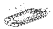
- FIG. 1 is a schematic exploded perspective view of the smartphone according to the first embodiment.
- FIG. 2 is a schematic front perspective view of the smartphone according to the first embodiment.
- FIG. 3 is a schematic rear perspective view of the smartphone according to the first embodiment.
- FIG. 4 is a schematic partial exploded perspective view of the smartphone according to the first embodiment.
- FIG. 5A is a schematic perspective view illustrating a mounting portion of the lock member according to the first exemplary embodiment.
- FIG. 5B is a schematic perspective view illustrating a mounting portion of the lock member according to the first exemplary embodiment.
- FIG. 6 is a schematic diagram illustrating how the lock member according to the first embodiment is attached.
- FIG. 7 is a perspective view of the locking member according to the first embodiment.
- FIG. 1 is a schematic exploded perspective view of the smartphone according to the first embodiment.
- FIG. 2 is a schematic front perspective view of the smartphone according to the first embodiment.
- FIG. 3 is a schematic rear perspective view of the smartphone according to the first embodiment.
- FIG. 8A is a part of a hexahedral view of the locking member according to the first exemplary embodiment.
- FIG. 8B is a part of a hexahedral view of the locking member according to the first exemplary embodiment.
- FIG. 8C is a part of a hexahedral view of the lock member according to the first exemplary embodiment.
- FIG. 8D is a part of a hexahedral view of the lock member according to the first exemplary embodiment.
- FIG. 8E is a part of a hexahedral view of the locking member according to the first exemplary embodiment.
- FIG. 8F is a part of a hexahedral view of the lock member according to the first exemplary embodiment.
- FIG. 9A is a schematic cross-sectional view of a predetermined portion of the lock member according to the first embodiment.
- FIG. 9B is a schematic cross-sectional view of a predetermined portion of the lock member according to the first exemplary embodiment.
- FIG. 9C is a schematic cross-sectional view of a predetermined portion of the lock member according to the first exemplary embodiment.
- FIG. 10 is a schematic perspective view of the battery lid according to the first embodiment when viewed from the inside.
- FIG. 11A is an enlarged perspective view of a structural portion provided in the battery lid according to the first exemplary embodiment.
- FIG. 11B is an enlarged perspective view of a structural portion provided in the battery lid according to the first embodiment.
- FIG. 12 is a schematic rear view of the smartphone before battery lid attachment according to the first exemplary embodiment.
- FIG. 13A is a schematic cross-sectional schematic diagram of the smartphone according to the first embodiment.
- FIG. 13B is a schematic cross-sectional schematic diagram of the smartphone according to the first embodiment.
- FIG. 14A is a schematic partial enlarged cross-sectional schematic diagram of the smartphone according to the first embodiment.
- FIG. 14B is a schematic partial enlarged cross-sectional schematic diagram of the smartphone according to the first embodiment.
- FIG. 15 is a schematic rear view of the smartphone in the process of attaching the battery lid according to the first embodiment.
- FIG. 16A is a schematic cross-sectional schematic diagram of the smartphone according to the first embodiment.
- FIG. 16B is a schematic cross-sectional schematic diagram of the smartphone according to the first embodiment.
- FIG. 16A is a schematic cross-sectional schematic diagram of the smartphone according to the first embodiment.
- FIG. 16B is a schematic cross-sectional schematic diagram of the smartphone according to the first embodiment.
- FIG. 17A is a schematic partial enlarged cross-sectional schematic diagram of the smartphone according to the first embodiment.
- FIG. 17B is a schematic partial enlarged cross-sectional schematic diagram of the smartphone according to the first embodiment.
- FIG. 18 is a schematic rear view of the smartphone after the battery lid according to the first embodiment is attached.
- FIG. 19A is a schematic cross-sectional schematic diagram of the smartphone according to the first embodiment.
- FIG. 19B is a schematic cross-sectional schematic diagram of the smartphone according to the first embodiment.
- FIG. 20A is a schematic partial enlarged cross-sectional schematic diagram of the smartphone according to the first embodiment.
- FIG. 20B is a schematic partially enlarged cross-sectional schematic diagram of the smartphone according to the first embodiment.
- FIG. 21 is an explanatory diagram illustrating a state in which the lock member according to the first embodiment is pivotally supported.
- FIG. 22 is a schematic rear view of the smartphone before battery lid attachment according to the first embodiment.
- FIG. 23 is a schematic cross-sectional schematic diagram of the smartphone according to the first embodiment.
- FIG. 24 is a schematic partial enlarged cross-sectional schematic diagram of the smartphone according to the first embodiment.
- Embodiment 1 As will be apparent from the description below, the smartphone 100 (see FIGS. 1 to 4) according to the present embodiment is held by the battery lid 60 attached to the main body, and is rotatable by the main body. And a lock member 70 that rotates according to the force received from the battery and engages with the battery lid 60. Thereby, the attachment of the battery cover 60 to the main body can be facilitated.
- the main body of the smartphone 100 should be interpreted in a broad sense and does not necessarily have to be in a completed state.
- the smartphone 100 after attaching the battery cover 60 to the smartphone body, there is no trouble for the user to manually switch the lock device from the unlocked state to the locked state, and the state of the lock device is changed as such. I will never forget.
- the smartphone 100 fully considers the actual use state of the user, and has an effect more than the ease of attachment. For example, as will be apparent from the following description, since the lock device is built in the smartphone 100, the lock device can be prevented from unintentionally going from the locked state to the unlocked state. Moreover, since the locking device exists inside the smartphone 100, the degree of freedom in designing the smartphone 100 can be increased. Note that the effects described in the embodiments are merely exemplary, and it is not permitted to narrowly interpret the technical scope of the present invention based on this description.
- a smartphone mobile communication terminal (electronic device)
- a smartphone includes an upper case assembly 10, a display assembly 20, a circuit board assembly 30, a lower case assembly 40, a battery pack 50, and a battery cover. (Lid member) 60 is provided.
- the upper case assembly 10 is a component in which the touch panel 15 that protects the display portion of the display assembly 20 and the upper case (molded product such as resin) are integrated.
- the display assembly 20 is a composite part including display parts such as an LCD (Liquid Crystal Display).
- the circuit board assembly 30 is a composite component in which circuit elements (processor, memory, logic chip, capacitor, LED, etc.) are mounted on an insulating substrate.
- the lower case assembly 40 is a component in which wiring, connection terminals, and the like are integrated with a lower case (molded product such as resin).
- the battery pack 50 is a flat plate member in which a secondary battery is incorporated and a plurality of external connection terminals are provided outside.
- the battery lid 60 is a molded product such as a resin.
- the touch panel 15 provided in the upper case assembly 10 is, for example, a capacitance type, and a user operation instruction is input based on detection of a change in capacitance due to contact with a touch pen or a user's finger. Detect position.
- the position detection performed by the touch panel 15 is performed by a dedicated circuit provided in the touch panel 15, but is not limited thereto, and may be performed by a circuit in the circuit board assembly 30.
- An arbitrary image such as an icon for receiving an input of an operation instruction by the user is displayed on a display such as an LCD provided in the display assembly 20.
- the smartphone 100 detects whether the icon displayed on the display is selected by the user based on the detection of the touch position by the touch panel 15, and the predetermined process that the icon displays in response to the detection of the selection of the icon Execute.
- the processing executed by the smartphone 100 is realized by an arithmetic processor (CPU) mounted on the circuit board assembly 30 executing a program.
- CPU arithmetic processor
- peripheral devices transmitters, receivers, various sensors
- the like mounted on the circuit board assembly 30 are driven and controlled.
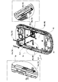
- the lower case assembly 40 is a member having a frame body portion 41 that is rectangular when viewed from above, and has a housing portion 42 that houses the circuit board assembly 30 and the display assembly 20.
- the upper case assembly 10 is screwed to the lower case assembly 40.
- the housing of the smartphone 100 is mainly configured by the upper case assembly 10, the frame portion of the lower case assembly 40, and the battery lid 60.
- the smartphone 100 is a portable small computer having an Internet wireless connection function in addition to a mobile phone function. Note that the lock mechanism described later can also be applied to electronic devices other than smartphones.
- the lower case assembly 40 has an accommodating portion 43 that accommodates the battery pack 50.
- the battery pack 50 is attached to the housing portion 43 of the lower case assembly 40 and fixed in position there. In this state, by pressing the battery lid 60 against the lower case assembly 40, the battery lid 60 is locked to the lower case assembly 40 via the lock member 70, and the battery pack 50 is placed inside the smartphone 100. It is stored in.
- the mode of securing the electrical connection between the battery pack 50 and the circuit board assembly 30 is arbitrary.
- the battery pack 50 is electrically connected to the circuit board assembly 30 via the lower case assembly 40 by being disposed in the accommodating portion 43 of the lower case assembly 40. That is, the external connection terminal of the battery pack 50 and the connection terminal of the lower case assembly 40 are electrically connected by contact or the like, and the battery pack 50 is connected to the circuit board assembly 30 via the wiring provided in the lower case assembly 40.
- power is supplied. Electric power may be supplied directly from the battery pack 50 to the circuit board assembly 30.
- the battery lid 60 by pushing the battery lid 60 into the lower case assembly 40, the battery lid 60 is locked to the lower case assembly 40. Accordingly, it is possible to facilitate attachment of the battery cover 60 to the lower case assembly 40, that is, the main body of the smartphone 100. Also in this case, since the detachment of the battery cover 60 from the lower case assembly 40 is suppressed by an impact caused by the falling of the smartphone 100, the impact resistance of the smartphone 100 is not impaired. As a result, it is possible to facilitate the attachment of the battery cover of the smartphone 100 without impairing the impact resistance of the smartphone 100.
- the smartphone 100 may be bent in a bow shape or the like.
- the battery pack 50 since the battery pack 50 is less bent than the lower case assembly 40, the battery pack 50 may jump out of the lower case assembly 40.
- the battery pack will further increase in size in the future. As the battery pack becomes larger, it is considered that the force that the battery pack tries to jump out at the time of a drop impact increases accordingly.
- the attachment of the battery lid 60 of the smartphone 100 can be facilitated without impairing the impact resistance of the smartphone 100. This makes it possible to cope with future enlargement of the battery pack.
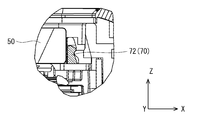
- FIG. 5A a lock member 70 is disposed in a concave accommodating portion 43 provided in the lower case assembly 40.
- FIG. 5B shows a partially enlarged view in the vicinity of a range surrounded by a dotted circle in FIG. 5A.
- a holding portion 46 that pivotally supports the lock member 70 is provided on the side surface 44 of the housing portion 43.
- the lock member 70 is inserted into a gap between the bottom surface 45 of the housing portion 43 and the holding portion 46, and is supported by the holding portion 46 on the bottom surface 45 from above. In this way, the lock member 70 is arranged in the accommodating portion 43 in a rotatable manner.
- a pair of lock members 70a and 70b are arranged at positions facing each other.
- the lock member 70a is attached to the smartphone body as schematically shown by the arrow AL2.
- the lock member 70b is attached to the smartphone body as schematically shown by the arrow AL3.
- 6 is a perspective view seen from the direction along the arrow AL1, and the two-dot chain line portion in FIG. 6 is an enlarged perspective view around the lock member.
- the lock member 70a is held by the holding portion 46a, and the lock member 70b is held by the holding portion 46b.
- the lock member 70 is easily arranged in the housing portion 43.
- the lock members 70a and 70b are members having mirror image symmetry. In order to avoid duplicate explanations, one of them may be described with attention.
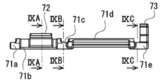
- FIGS. 8A to 8F show six views of the lock member
- FIGS. 9A to 9C show partial sectional views of the lock member.
- the lock member 70 is a shaft-like member extending with the y-axis direction as a longitudinal direction, and is rotatably held by the lower case assembly 40 in the xz plane.
- the lock member 70 includes a shaft-like portion 71 that extends along the y-axis, a hook portion 72, and a receiving portion 73.
- the shaft-shaped portion 71 is a structure in which a ring-shaped portion 71a, an intermediate portion 71b, a ring-shaped portion 71c, an intermediate portion 71d, and a ring-shaped portion 71e are continuous.
- the hook part 72 is provided in the intermediate part 71b.
- the hook portion 72 is a portion (engagement portion) that meshes with a hook portion (illustrated in FIG. 10) provided on the battery lid 60.
- the hook portion 72 of the lock member 70 held by the lower case assembly 40 and the hook portion provided on the battery lid 60 are engaged with each other, whereby the battery lid 60 is locked to the lower case assembly 40 via the lock member 70. Is done.
- the engagement between the hook portion 72 of the lock member 70 and the hook portions provided on the battery lid 60 may be referred to as fitting of the lock member 70 and the battery lid 60.
- this state may be simply referred to as a locked state.
- the opposite of the locked state is the unlocked state.
- the receiving part 73 is provided in the ring-shaped part 71e.
- the receiving portion 73 is a portion that receives a force from a protruding portion (illustrated in FIG. 10) provided on the battery lid 60.
- a protruding portion illustrated in FIG. 10
- the lock member 70 rotates in a direction away from the battery pack 50. This makes it possible to secure the engagement between the hook portions as described above.
- a relatively simple lock mechanism can be obtained. Of course, the rotation direction of the lock member 70 may be reversed.
- the hook part 72 has a base part 72a and a tapered part 72b.
- the taper portion 72b becomes thin as it is separated from the base portion 72a.
- the specific shape of the hook portion 72 is not limited to this and is arbitrary.
- the receiving portion 73 is a bent portion having a standing portion 73a, an inclined portion 73b, and a bent portion 73c.
- the standing portion 73a and the inclined portion 73b extend along the z-axis.
- the extending direction of the standing part 73a and the extending direction of the inclined part 73b are different from each other.
- the specific shape of the receiving portion 73 is not limited to this and is arbitrary.
- FIG. 8A is a top view of the lock member 70
- FIG. 8B is an outer side view of the lock member 70
- FIG. 8C is a bottom view of the lock member 70
- FIG. 8D is an inner side surface of the lock member 70
- FIG. 8E is a front side view of the locking member 70
- FIG. 8F is a rear side view of the locking member 70.
- the battery pack 50 side is the inside, and the opposite side is the outside.
- the hook portion 72 side is the front side
- the receiving portion 73 side is the rear side.
- the angle ⁇ formed by the inclined portion 73b with respect to the standing portion 73a is in the range of 0 to 90 degrees, for example, 40 to 60 degrees.
- FIG. 9A is an end view taken along IXA-IXA in FIG. 8B
- FIG. 9B is an end view taken along IXB-IXB in FIG. 8B
- FIG. 9C is an end view taken along IXC-IXC in FIG. 8B.
- the ring-shaped portion 71c has an end surface shape in which a protrusion 71c2 is provided on the outer periphery of the circular portion 71c1.
- the ring-shaped portion 71e has an end surface shape in which a protrusion 71e2 is provided on the outer periphery of the circular portion 71e1.
- the protrusion is provided to restrict the rotation range of the lock member 70. By restricting the rotation range of the lock member 70, it is possible to effectively prevent the hook members from being engaged with each other due to excessive rotation of the lock member 70 or the like.
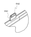
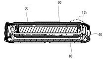
- the battery lid 60 is a flat plate member, and a hook portion (engagement portion) 61 and a projection portion (pressing portion) 62 rising from the inner surface extend along the outer periphery of the battery lid 60. Are arranged at regular intervals.
- the hook portion 61 of the battery lid 60 is a portion that meshes with the hook portion 72 of the lock member 70.
- the protruding portion 62 of the battery lid 60 is a portion that abuts on the receiving portion 73 of the lock member 70 and presses the receiving portion 73.
- the battery lid 60 is provided with a convex portion 63 that extends along the outer periphery of the battery pack 50.
- the position of the battery pack 50 is regulated by the convex portion 63 of the battery lid 60.
- a ring-shaped sealing member 65 such as an O-ring is provided on the outer periphery of the convex portion 63 of the battery lid 60.
- the seal member 65 is sandwiched between the battery lid 60 and the lower case assembly 40 and deformed and held between the two. Thereby, watertightness between the battery lid 60 and the lower case assembly 40 is ensured.
- a plurality of protrusions 67 that mesh with the lower case assembly 40 are provided on the outer periphery of the battery lid 60.
- the protrusion 67 is a hook-shaped portion, and is provided so that the hook faces the outside. This is the opposite of the hook part 61.
- FIG. 11A shows an enlarged perspective view near the dotted circle 11a in FIG. 10, and FIG. 11B shows an enlarged perspective view near the dotted circle 11b in FIG.
- the hook portion 61 has an upright portion 61b1 and a flange portion 61b2.
- the upright portion 61 b 1 extends along the direction in which the battery lid 60 is pushed into the lower case assembly 40.
- the flange portion 61b2 extends inward from the top portion of the standing portion 61b1.
- the protrusion 62 (62a) is a triangular portion extending along the direction in which the battery lid 60 is pushed into the lower case assembly 40. As shown in FIG. 11B, the protrusion 62a becomes narrower as it extends upward.
- the protrusion 62 (62a) has an inclined surface 62a1 that is inclined downward from the inside toward the outside.
- FIGS. 13A is a schematic cross-sectional schematic diagram between XIIIA and XIIIA in FIG. 12, and FIG. 13B is a schematic cross-sectional schematic diagram between XIIIB and XIIIB in FIG. 14A is a schematic enlarged view around the dotted circle 14a in FIG. 13A, and FIG. 14B is a schematic enlarged view around the dotted circle 14b in FIG. 13B.
- FIGS. 16A is a schematic cross-sectional schematic diagram between XVIA and XVIA in FIG. 15, and FIG. 16B is a schematic cross-sectional schematic diagram between XVIB and XVIB in FIG. 17A is a schematic enlarged view around the dotted line circle 17a in FIG. 16A, and FIG. 17B is a schematic enlarged view around the dotted line circle 17b in FIG. 16B.
- FIG. 18 to 20B show a state after the battery cover 60 is pushed into the lower case assembly 40.
- 19A is a schematic cross-sectional schematic diagram between XIXA and XIXA in FIG. 18, and FIG. 19B is a schematic cross-sectional schematic diagram between XIXB and XIXB in FIG. 20A is a schematic enlarged view around the dotted line circle 20a in FIG. 19A, and FIG. 20B is a schematic enlarged view around the dotted line circle 20b in FIG. 19B.
- the lock member 70 is standing on the bottom surface 45.
- the rising direction (extending direction) of the hook portion 72 of the lock member 70 substantially coincides with the z-axis (the thickness direction of the battery pack 50).
- the bent portion 73 c of the receiving portion 73 of the lock member 70 is in a state close to the outer peripheral side surface of the battery pack 50.
- the battery lid 60 When the battery lid 60 is pushed into the lower case assembly 40, the battery lid 60 is locked to the lower case assembly 40 via the lock member 70 by the following mechanism.
- the battery lid 60 When the battery lid 60 is pushed into the lower case assembly 40, the battery lid 60 is lowered to the bottom surface 45 side of the lower case assembly 40. When the battery lid 60 is lowered to a predetermined depth, the protrusion 62 of the battery lid 60 comes into contact with the receiving portion 73 of the lock member 70 (see FIG. 17B). As the battery lid 60 is further lowered, the receiving portion 73 of the lock member 70 is pushed outward (in a direction away from the outer peripheral side surface of the battery pack 50) by receiving a force from the protrusion 62 of the battery lid 60. As described above, the rotation shaft of the lock member 70 is pivotally supported by the holding portion 46 of the lower case assembly 40.
- the lock member 70 rotates outward while staying in place as schematically shown in FIG. 17B. As the battery cover 60 is further lowered, the lock member 70 further rotates outward while staying in place. In addition, you may grasp
- the lock member 70 is a single part in which the receiving portion 73 and the hook portion 72 are provided integrally with the shaft-like portion 71 as shown in FIG. Accordingly, as described above, when the receiving portion 73 receives a force from the protrusion 62 of the battery lid 60 and the lock member 70 is tilted to the outside while being in place, the hook integrally provided with the lock member 70 is provided. The part 72 is also inclined outward.
- the battery lid 60 is provided with a hook portion 61 in advance, and the hook portion 61 is lowered as the battery lid 60 is lowered. In the process in which the hook portion 72 of the lock member 70 gradually falls outward, the hook portion 61 of the battery lid 60 gradually falls (see FIG. 17A).
- the battery lid 60 is locked to the lower case assembly 40.
- the battery lid 60 is automatically locked with respect to the lower case assembly 40. It becomes. That is, the battery lid 60 can be easily attached to the lower case assembly 40.
- the user is not forced to perform the operation of locking the lock mechanism. Therefore, forgetting to lock by the user can be effectively suppressed. This point is a particularly advantageous effect in a smartphone having water tightness as in the present embodiment.
- the lock member 70 is disposed in the lower case assembly 40, and the lock mechanism (the contact and engagement structure between the lock member 70 and the battery lid 60) does not appear on the appearance of the smartphone 100. ing. Thereby, it can suppress effectively that a lock state is cancelled
- the height H1 of the receiving portion 73 of the lock member 70 is set higher than the height H2 of the hook portion 72 of the lock member 70, and the battery lid 60 is provided.
- the height H3 of the protrusion 62 is set to be lower than the height H4 of the hook 61 of the battery lid 60.
- the lock member 70 can receive the force from the protrusion 62 more sufficiently, and the rotation amount of the lock member 70 can be sufficient. can do. That the height H2 of the hook part 72 is low can be easily compensated by increasing the height H4 of the hook part 61. As a result, a sufficient amount of rotation of the lock member 70 can be ensured, and the battery lid 60 can be more sufficiently drawn and held on the lower case assembly 40 side.
- a ring-shaped sealing member 65 such as an O-ring is provided in advance on the battery lid 60 in order to ensure water tightness.
- the seal member 65 is, for example, an elastically deformable ring rubber.
- the seal member 65 is deformed between the battery lid 60 and the lower case assembly 40 and is held between the two in this state. Thereby, watertightness can be imparted to the battery lid 60 portion of the smartphone 100.
- the battery lid 60 is more sufficiently drawn and held on the lower case assembly 40 side in accordance with securing a sufficient amount of rotation of the lock member 70. As a result, it is possible to more effectively suppress the loss of water tightness.
- the deformation of the seal member 65 is not explicitly shown in the drawings, but is equivalent to that shown to those skilled in the art.
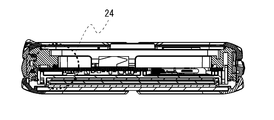
- FIG. 23 is a schematic cross-sectional schematic view taken along the line XXIII-XXIII in FIG.
- FIG. 24 is a schematic enlarged view around the dotted circle 24 in FIG.
- the lock member 70 is pressed and held downward by the holding portion 46 at three locations P10 to P12.
- the rotation axis AX10 of the lock member 70 can be positioned more accurately.
- the ring-shaped portion 71c of the lock member 70 is sandwiched and held between the holding portion 46 and the substrate 47.
- the holding portion 46 is previously provided with a receiving portion 46 c that receives the ring-shaped portion 71 c of the lock member 70.
- the height of the inlet of the receiving portion 46c is lower than the diameter of the circular portion 71c1, but since the holding portion 46 and the substrate 47 are separate members, the ring-shaped portion 71c can be easily placed in the receiving portion 46c. It can be pushed in.
- the lock member 70 is attached to the lower case assembly 40 by pressing. Thereby, the complexity of the operation of attaching the lock mechanism to the smartphone 100 can be avoided.
- the lock member 70 is provided with a protrusion that functions as a rotation restricting portion.
- the rotation range of the lock member 70 can be suitably restricted, and the lock operation itself can be effectively prevented from being damaged by an unexpected rotation of the lock member 70.
- removing the battery lid 60 from the lower case assembly 40 can be easily performed by forcibly pulling the battery lid 60.
- the method of assembling the smartphone 100 is arbitrary, and can be easily understood by those skilled in the art from the illustration of the present application.
- the present invention is not limited to the above-described embodiment, and can be changed as appropriate without departing from the spirit of the present invention.
- the present invention can also be applied to electronic devices other than smartphones (tablet terminals, sheet computers, mobile computers, PHS, PDAs, etc.).
- the specific shape of the hook portions that mesh with each other is arbitrary.
- the specific shape of the lock member 70 is arbitrary.
- the position of the lock member 70 in the lower case assembly 40 is arbitrary.
- the number of lock members 70 provided in the lower case assembly 40 is arbitrary.
- the lid member includes a pressing portion that applies the force to the locking member, and an engaging portion that engages with the engaging portion of the locking member in response to the contact of the pressing portion with the locking member.
- (Appendix 4) 4. The electronic device according to claim 1, wherein the lock member includes a receiving portion that receives the force from the lid member, and an engagement portion that engages with the lid member. 5.
- the locking member extends in a direction perpendicular to the pushing direction of the lid member with respect to the main body as a longitudinal direction, and the receiving portion and the engaging portion of the locking member are extended of the locking member. 4.
- the lid member includes a pressing portion that applies the force to the locking member, and an engaging portion that engages with the engaging portion of the locking member in response to the contact of the pressing portion with the locking member.
- the electronic device according to any one of appendices 1 to 4, wherein the lock member extends with a direction perpendicular to a pushing direction of the lid member with respect to the main body as a longitudinal direction, and the lid The electronic device according to any one of appendices 1 to 4, wherein the pressing portion and the engaging portion of the member are sequentially arranged along an extending direction of the lock member.
- the battery pack further confined in the housing space of the main body by the lid member, and the lock member rotates in a direction away from the battery pack in response to contact with the lid member.
- the electronic device according to any one of 1 to 5.
- Appendix 9 The electronic device according to any one of appendices 1 to 8, wherein the lock member is rotatably held by the main body at a plurality of locations spaced along the extending direction of the lock member. machine.
- Appendix 10 The electronic device according to any one of appendices 1 to 9, wherein the lock member is rotatably held by the main body by being fitted in a space provided in advance in the main body.
Abstract
Description
後述の説明から明らかなように、本実施形態に係るスマートフォン100(図1乃至図4参照)は、本体に対して取り付けられる電池フタ60と、本体によって回転可能に保持されると共に、電池フタ60から受けた力に応じて回転し、電池フタ60に対して係合するロック部材70と、を備える。これによって、本体に対する電池フタ60の取り付けを容易化することができる。なお、スマートフォン100の本体とは、広義に解釈されるべきものであり、必ずしも完成状態である必要はない。
As will be apparent from the description below, the smartphone 100 (see FIGS. 1 to 4) according to the present embodiment is held by the
本体に対して取り付けられる蓋部材と、前記本体によって回転可能に保持されると共に、前記蓋部材から受けた力に応じて回転し、前記蓋部材に対して係合するロック部材と、を備え、前記蓋部材に対する前記ロック部材の前記係合によって、前記蓋部材は、前記ロック部材を介して前記本体に対して係止される、電子機器。 (Appendix 1)
A lid member attached to the main body, and a lock member that is rotatably held by the main body, rotates according to the force received from the lid member, and engages with the lid member; The electronic device, wherein the lid member is locked to the main body via the lock member by the engagement of the lock member with the lid member.
前記ロック部材は、前記蓋部材から前記力を受ける受け部と、前記蓋部材に対して係合する係合部と、を備えることを特徴とする付記1に記載の電子機器。 (Appendix 2)
The electronic device according to
前記蓋部材は、前記ロック部材に対して前記力を与える押し付け部と、前記ロック部材に対する前記押し付け部の当接に応じて前記ロック部材の前記係合部が係合する係合部と、を備えることを特徴とする付記1又は2に記載の電子機器。 (Appendix 3)
The lid member includes a pressing portion that applies the force to the locking member, and an engaging portion that engages with the engaging portion of the locking member in response to the contact of the pressing portion with the locking member. The electronic apparatus according to
前記ロック部材は、前記蓋部材から前記力を受ける受け部と、前記蓋部材に対して係合する係合部と、を備える、付記1乃至3のいずれか一項に記載の電子機器であって、前記ロック部材は、前記本体に対する前記蓋部材の押し込み方向に対して直交する方向を長手方向として延在し、前記ロック部材の前記受け部及び前記係合部は、前記ロック部材の延在方向に沿って順に配置されていることを特徴とする付記1乃至3のいずれか一項に記載の電子機器。 (Appendix 4)
4. The electronic device according to
前記蓋部材は、前記ロック部材に対して前記力を与える押し付け部と、前記ロック部材に対する前記押し付け部の当接に応じて前記ロック部材の前記係合部が係合する係合部と、を備える、付記1乃至4のいずれか一項に記載の電子機器であって、前記ロック部材は、前記本体に対する前記蓋部材の押し込み方向に対して直交する方向を長手方向として延在し、前記蓋部材の前記押し付け部及び係合部は、前記ロック部材の延在方向に沿って順に配置されていることを特徴とする付記1乃至4のいずれか一項に記載の電子機器。 (Appendix 5)
The lid member includes a pressing portion that applies the force to the locking member, and an engaging portion that engages with the engaging portion of the locking member in response to the contact of the pressing portion with the locking member. The electronic device according to any one of
前記蓋部材によって前記本体の収容空間内に閉じ込められる電池パックを更に備え、前記ロック部材は、前記蓋部材との接触に応じて、前記電池パックから離間する方向に回転することを特徴とする付記1乃至5のいずれか一項に記載の電子機器。 (Appendix 6)
The battery pack further confined in the housing space of the main body by the lid member, and the lock member rotates in a direction away from the battery pack in response to contact with the lid member. The electronic device according to any one of 1 to 5.
前記蓋部材によって前記本体の収容空間内に閉じ込められる電池パックを更に備え、前記本体に対する前記蓋部材の押し込み方向に沿う前記ロック部材の高さは、同方向に沿う前記電池パックの厚みよりも低いことを特徴とする付記1乃至6のいずれか一項に記載の電子機器。 (Appendix 7)
The battery pack is further confined in the housing space of the main body by the lid member, and the height of the lock member along the pushing direction of the lid member with respect to the main body is lower than the thickness of the battery pack along the same direction. The electronic device according to any one of
前記蓋部材によって前記本体の収容空間内に閉じ込められる電池パックを更に備え、前記ロック部材は、前記電池パックの外周側面に沿って延在することを特徴とする付記1乃至7のいずれか一項に記載の電子機器。 (Appendix 8)
The battery pack further confined within the housing space of the main body by the lid member, and the lock member extends along an outer peripheral side surface of the battery pack. The electronic device as described in.
前記ロック部材は、前記本体によって、前記ロック部材の延在方向に沿って離間した複数の箇所において回転可能に保持されていることを特徴とする付記1乃至8のいずれか一項に記載の電子機器。 (Appendix 9)
The electronic device according to any one of
前記ロック部材は、前記本体に予め設けられた空間に嵌め込まれることで前記本体によって回転可能に保持されることを特徴とする付記1乃至9のいずれか一項に記載の電子機器。 (Appendix 10)
The electronic device according to any one of
20 ディスプレイアセンブリ
30 回路基板アセンブリ
40 下ケースアセンブリ
50 電池パック
60 電池フタ
61 フック部
62 突起部
63 凸部
65 シール部材
70 ロック部材
71 軸状部
72 フック部
73 受け部 DESCRIPTION OF
Claims (10)
- 本体に対して取り付けられる蓋部材と、
前記本体によって回転可能に保持されると共に、前記蓋部材から受けた力に応じて回転し、前記蓋部材に対して係合するロック部材と、を備え、
前記蓋部材に対する前記ロック部材の前記係合によって、前記蓋部材は、前記ロック部材を介して前記本体に対して係止される、電子機器。 A lid member attached to the main body;
A lock member that is rotatably held by the main body, rotates according to a force received from the lid member, and engages with the lid member;
The electronic device, wherein the lid member is locked to the main body via the lock member by the engagement of the lock member with the lid member. - 前記ロック部材は、
前記蓋部材から前記力を受ける受け部と、
前記蓋部材に対して係合する係合部と、
を備えることを特徴とする請求項1に記載の電子機器。 The locking member is
A receiving portion for receiving the force from the lid member;
An engaging portion that engages with the lid member;
The electronic apparatus according to claim 1, further comprising: - 前記蓋部材は、
前記ロック部材に対して前記力を与える押し付け部と、
前記ロック部材に対する前記押し付け部の当接に応じて前記ロック部材の前記係合部が係合する係合部と、
を備えることを特徴とする請求項1又は2に記載の電子機器。 The lid member is
A pressing portion that applies the force to the locking member;
An engagement portion with which the engagement portion of the lock member is engaged according to the contact of the pressing portion with the lock member;
The electronic apparatus according to claim 1, further comprising: - 前記ロック部材は、前記蓋部材から前記力を受ける受け部と、前記蓋部材に対して係合する係合部と、を備える、請求項1乃至3のいずれか一項に記載の電子機器であって、
前記ロック部材は、前記本体に対する前記蓋部材の押し込み方向に対して直交する方向を長手方向として延在し、
前記ロック部材の前記受け部及び前記係合部は、前記ロック部材の延在方向に沿って順に配置されていることを特徴とする請求項1乃至3のいずれか一項に記載の電子機器。 The electronic device according to claim 1, wherein the lock member includes a receiving portion that receives the force from the lid member, and an engagement portion that engages with the lid member. There,
The lock member extends with the direction perpendicular to the pushing direction of the lid member against the main body as a longitudinal direction,
4. The electronic device according to claim 1, wherein the receiving portion and the engaging portion of the lock member are sequentially arranged along an extending direction of the lock member. 5. - 前記蓋部材は、前記ロック部材に対して前記力を与える押し付け部と、前記ロック部材に対する前記押し付け部の当接に応じて前記ロック部材の前記係合部が係合する係合部と、を備える、請求項1乃至4のいずれか一項に記載の電子機器であって、
前記ロック部材は、前記本体に対する前記蓋部材の押し込み方向に対して直交する方向を長手方向として延在し、
前記蓋部材の前記押し付け部及び係合部は、前記ロック部材の延在方向に沿って順に配置されていることを特徴とする請求項1乃至4のいずれか一項に記載の電子機器。 The lid member includes a pressing portion that applies the force to the locking member, and an engaging portion that engages with the engaging portion of the locking member in response to the contact of the pressing portion with the locking member. An electronic device according to any one of claims 1 to 4, comprising:
The lock member extends with the direction perpendicular to the pushing direction of the lid member against the main body as a longitudinal direction,
5. The electronic device according to claim 1, wherein the pressing portion and the engaging portion of the lid member are sequentially arranged along an extending direction of the lock member. - 前記蓋部材によって前記本体の収容空間内に閉じ込められる電池パックを更に備え、
前記ロック部材は、前記蓋部材との接触に応じて、前記電池パックから離間する方向に回転することを特徴とする請求項1乃至5のいずれか一項に記載の電子機器。 A battery pack confined in the housing space of the main body by the lid member;
The electronic device according to claim 1, wherein the lock member rotates in a direction away from the battery pack in response to contact with the lid member. - 前記蓋部材によって前記本体の収容空間内に閉じ込められる電池パックを更に備え、
前記本体に対する前記蓋部材の押し込み方向に沿う前記ロック部材の高さは、同方向に沿う前記電池パックの厚みよりも低いことを特徴とする請求項1乃至6のいずれか一項に記載の電子機器。 A battery pack confined in the housing space of the main body by the lid member;
7. The electron according to claim 1, wherein a height of the lock member along a pushing direction of the lid member with respect to the main body is lower than a thickness of the battery pack along the same direction. machine. - 前記蓋部材によって前記本体の収容空間内に閉じ込められる電池パックを更に備え、
前記ロック部材は、前記電池パックの外周側面に沿って延在することを特徴とする請求項1乃至7のいずれか一項に記載の電子機器。 A battery pack confined in the housing space of the main body by the lid member;
The electronic device according to claim 1, wherein the lock member extends along an outer peripheral side surface of the battery pack. - 前記ロック部材は、前記本体によって、前記ロック部材の延在方向に沿って離間した複数の箇所において回転可能に保持されていることを特徴とする請求項1乃至8のいずれか一項に記載の電子機器。 The said lock member is rotatably hold | maintained by the said main body in the several place spaced apart along the extension direction of the said lock member, The Claim 1 thru | or 8 characterized by the above-mentioned. Electronics.
- 前記ロック部材は、前記本体に予め設けられた空間に嵌め込まれることで前記本体によって回転可能に保持されることを特徴とする請求項1乃至9のいずれか一項に記載の電子機器。 10. The electronic apparatus according to claim 1, wherein the lock member is rotatably held by the main body by being fitted in a space provided in advance in the main body.
Priority Applications (4)
| Application Number | Priority Date | Filing Date | Title |
|---|---|---|---|
| JP2013500864A JP6156140B2 (en) | 2011-02-24 | 2012-02-13 | Electronics |
| EP12749067.0A EP2680545A4 (en) | 2011-02-24 | 2012-02-13 | Electronic apparatus |
| US13/981,247 US9345153B2 (en) | 2011-02-24 | 2012-02-13 | Electronic device |
| CN201280010223.5A CN103404116B (en) | 2011-02-24 | 2012-02-13 | Electronic installation |
Applications Claiming Priority (2)
| Application Number | Priority Date | Filing Date | Title |
|---|---|---|---|
| JP2011-038971 | 2011-02-24 | ||
| JP2011038971 | 2011-02-24 |
Publications (1)
| Publication Number | Publication Date |
|---|---|
| WO2012114671A1 true WO2012114671A1 (en) | 2012-08-30 |
Family
ID=46720467
Family Applications (1)
| Application Number | Title | Priority Date | Filing Date |
|---|---|---|---|
| PCT/JP2012/000929 WO2012114671A1 (en) | 2011-02-24 | 2012-02-13 | Electronic apparatus |
Country Status (5)
| Country | Link |
|---|---|
| US (1) | US9345153B2 (en) |
| EP (1) | EP2680545A4 (en) |
| JP (1) | JP6156140B2 (en) |
| CN (1) | CN103404116B (en) |
| WO (1) | WO2012114671A1 (en) |
Cited By (3)
| Publication number | Priority date | Publication date | Assignee | Title |
|---|---|---|---|---|
| JP2014086512A (en) * | 2012-10-22 | 2014-05-12 | Fujitsu Ltd | Electronic apparatus |
| JP2015027057A (en) * | 2013-07-29 | 2015-02-05 | 京セラ株式会社 | Electronic apparatus and two-color molding |
| JP2015534276A (en) * | 2012-10-02 | 2015-11-26 | コーニンクレッカ フィリップス エヌ ヴェKoninklijke Philips N.V. | Housing with removable locking element |
Families Citing this family (3)
| Publication number | Priority date | Publication date | Assignee | Title |
|---|---|---|---|---|
| KR102651576B1 (en) * | 2016-10-18 | 2024-03-27 | 삼성전자주식회사 | electronic device including battery module and manufacturing method thereof |
| CN108520933A (en) * | 2018-06-22 | 2018-09-11 | 深圳市沃特沃德股份有限公司 | Battery component and electronic equipment |
| US11751354B1 (en) * | 2021-06-25 | 2023-09-05 | Amazon Technologies, Inc. | Anti-sag modular server chassis assembly |
Citations (4)
| Publication number | Priority date | Publication date | Assignee | Title |
|---|---|---|---|---|
| JP2006032089A (en) * | 2004-07-15 | 2006-02-02 | Matsushita Electric Ind Co Ltd | Portable electronic equipment |
| JP2007335132A (en) * | 2006-06-13 | 2007-12-27 | Sanyo Electric Co Ltd | Portable electronic device |
| JP2009290832A (en) | 2008-06-02 | 2009-12-10 | Casio Hitachi Mobile Communications Co Ltd | Cellular phone terminal |
| JP2011038971A (en) | 2009-08-17 | 2011-02-24 | Fujitsu Ltd | Sensor, power generator, and manufacturing method for the same |
Family Cites Families (5)
| Publication number | Priority date | Publication date | Assignee | Title |
|---|---|---|---|---|
| JP2000299570A (en) * | 1999-04-14 | 2000-10-24 | Sony Corp | Buckling device |
| CN101640258A (en) | 2008-07-30 | 2010-02-03 | 深圳富泰宏精密工业有限公司 | Battery cover opening-closing mechanism |
| CN101686272B (en) | 2008-09-26 | 2014-02-12 | 深圳富泰宏精密工业有限公司 | Battery cover locking structure |
| CN101964404B (en) | 2009-07-23 | 2013-08-07 | 深圳富泰宏精密工业有限公司 | Battery cover structure |
| CN102117899B (en) * | 2009-12-30 | 2014-03-26 | 深圳富泰宏精密工业有限公司 | Battery cover assembly |
-
2012
- 2012-02-13 CN CN201280010223.5A patent/CN103404116B/en not_active Expired - Fee Related
- 2012-02-13 WO PCT/JP2012/000929 patent/WO2012114671A1/en active Application Filing
- 2012-02-13 EP EP12749067.0A patent/EP2680545A4/en not_active Withdrawn
- 2012-02-13 JP JP2013500864A patent/JP6156140B2/en not_active Expired - Fee Related
- 2012-02-13 US US13/981,247 patent/US9345153B2/en not_active Expired - Fee Related
Patent Citations (4)
| Publication number | Priority date | Publication date | Assignee | Title |
|---|---|---|---|---|
| JP2006032089A (en) * | 2004-07-15 | 2006-02-02 | Matsushita Electric Ind Co Ltd | Portable electronic equipment |
| JP2007335132A (en) * | 2006-06-13 | 2007-12-27 | Sanyo Electric Co Ltd | Portable electronic device |
| JP2009290832A (en) | 2008-06-02 | 2009-12-10 | Casio Hitachi Mobile Communications Co Ltd | Cellular phone terminal |
| JP2011038971A (en) | 2009-08-17 | 2011-02-24 | Fujitsu Ltd | Sensor, power generator, and manufacturing method for the same |
Non-Patent Citations (1)
| Title |
|---|
| See also references of EP2680545A4 |
Cited By (3)
| Publication number | Priority date | Publication date | Assignee | Title |
|---|---|---|---|---|
| JP2015534276A (en) * | 2012-10-02 | 2015-11-26 | コーニンクレッカ フィリップス エヌ ヴェKoninklijke Philips N.V. | Housing with removable locking element |
| JP2014086512A (en) * | 2012-10-22 | 2014-05-12 | Fujitsu Ltd | Electronic apparatus |
| JP2015027057A (en) * | 2013-07-29 | 2015-02-05 | 京セラ株式会社 | Electronic apparatus and two-color molding |
Also Published As
| Publication number | Publication date |
|---|---|
| EP2680545A1 (en) | 2014-01-01 |
| CN103404116B (en) | 2015-12-02 |
| JP6156140B2 (en) | 2017-07-05 |
| US20130301197A1 (en) | 2013-11-14 |
| US9345153B2 (en) | 2016-05-17 |
| EP2680545A4 (en) | 2016-03-16 |
| JPWO2012114671A1 (en) | 2014-07-07 |
| CN103404116A (en) | 2013-11-20 |
Similar Documents
| Publication | Publication Date | Title |
|---|---|---|
| JP6156140B2 (en) | Electronics | |
| EP2713585B1 (en) | Electronic apparatus and method for assembling the same | |
| EP3547019B1 (en) | Display assembly and mobile terminal | |
| JP5976068B2 (en) | Electronic device with touch sensor device | |
| JP2006277116A (en) | Electronic equipment and hinge unit | |
| CN108600425B (en) | Display screen assembly and electronic equipment | |
| JP2015046115A (en) | Information processor | |
| JP6089296B2 (en) | Electronics | |
| US20130128469A1 (en) | Portable electronic device | |
| JP2012003620A (en) | Electronic device | |
| TWI487454B (en) | Electronic assembly and electronic apparatus | |
| JP2007207847A (en) | Electronic apparatus | |
| WO2015045132A1 (en) | Electronic apparatus and hinge unit | |
| WO2018196692A1 (en) | Card tray assembly, card tray and mobile terminal | |
| JP2012168704A (en) | Electronic apparatus | |
| WO2014097654A1 (en) | Electronic apparatus | |
| JP2014086980A (en) | Portable electronic apparatus | |
| US9055206B1 (en) | Electronic device | |
| US8243457B2 (en) | Electronic component mounting structure, electronic device and manufacturing method of an electronic device | |
| JP5102170B2 (en) | Electronics | |
| JP2019191302A (en) | Electronic apparatus, frame, and method for manufacturing the same | |
| CN216123087U (en) | Shell assembly and mobile terminal | |
| JP2013050973A (en) | Electronic device | |
| US20120249894A1 (en) | Television Apparatus and Electronic Device | |
| US9578146B2 (en) | Electronic assembly and electronic apparatus |
Legal Events
| Date | Code | Title | Description |
|---|---|---|---|
| 121 | Ep: the epo has been informed by wipo that ep was designated in this application |
Ref document number: 12749067 Country of ref document: EP Kind code of ref document: A1 |
|
| WWE | Wipo information: entry into national phase |
Ref document number: 2012749067 Country of ref document: EP |
|
| WWE | Wipo information: entry into national phase |
Ref document number: 13981247 Country of ref document: US |
|
| ENP | Entry into the national phase |
Ref document number: 2013500864 Country of ref document: JP Kind code of ref document: A |
|
| NENP | Non-entry into the national phase |
Ref country code: DE |