WO2012111825A1 - 画像処理装置、画像処理方法、及びプログラム - Google Patents
画像処理装置、画像処理方法、及びプログラム Download PDFInfo
- Publication number
- WO2012111825A1 WO2012111825A1 PCT/JP2012/053875 JP2012053875W WO2012111825A1 WO 2012111825 A1 WO2012111825 A1 WO 2012111825A1 JP 2012053875 W JP2012053875 W JP 2012053875W WO 2012111825 A1 WO2012111825 A1 WO 2012111825A1
- Authority
- WO
- WIPO (PCT)
- Prior art keywords
- image data
- still image
- image
- moving image
- main memory
- Prior art date
- Legal status (The legal status is an assumption and is not a legal conclusion. Google has not performed a legal analysis and makes no representation as to the accuracy of the status listed.)
- Ceased
Links
Images








Classifications
-
- H—ELECTRICITY
- H04—ELECTRIC COMMUNICATION TECHNIQUE
- H04N—PICTORIAL COMMUNICATION, e.g. TELEVISION
- H04N5/00—Details of television systems
- H04N5/76—Television signal recording
- H04N5/765—Interface circuits between an apparatus for recording and another apparatus
- H04N5/77—Interface circuits between an apparatus for recording and another apparatus between a recording apparatus and a television camera
- H04N5/772—Interface circuits between an apparatus for recording and another apparatus between a recording apparatus and a television camera the recording apparatus and the television camera being placed in the same enclosure
-
- H—ELECTRICITY
- H04—ELECTRIC COMMUNICATION TECHNIQUE
- H04N—PICTORIAL COMMUNICATION, e.g. TELEVISION
- H04N1/00—Scanning, transmission or reproduction of documents or the like, e.g. facsimile transmission; Details thereof
- H04N1/40—Picture signal circuits
-
- H—ELECTRICITY
- H04—ELECTRIC COMMUNICATION TECHNIQUE
- H04N—PICTORIAL COMMUNICATION, e.g. TELEVISION
- H04N19/00—Methods or arrangements for coding, decoding, compressing or decompressing digital video signals
- H04N19/42—Methods or arrangements for coding, decoding, compressing or decompressing digital video signals characterised by implementation details or hardware specially adapted for video compression or decompression, e.g. dedicated software implementation
- H04N19/436—Methods or arrangements for coding, decoding, compressing or decompressing digital video signals characterised by implementation details or hardware specially adapted for video compression or decompression, e.g. dedicated software implementation using parallelised computational arrangements
-
- H—ELECTRICITY
- H04—ELECTRIC COMMUNICATION TECHNIQUE
- H04N—PICTORIAL COMMUNICATION, e.g. TELEVISION
- H04N23/00—Cameras or camera modules comprising electronic image sensors; Control thereof
- H04N23/60—Control of cameras or camera modules
- H04N23/667—Camera operation mode switching, e.g. between still and video, sport and normal or high- and low-resolution modes
-
- H—ELECTRICITY
- H04—ELECTRIC COMMUNICATION TECHNIQUE
- H04N—PICTORIAL COMMUNICATION, e.g. TELEVISION
- H04N23/00—Cameras or camera modules comprising electronic image sensors; Control thereof
- H04N23/80—Camera processing pipelines; Components thereof
-
- H—ELECTRICITY
- H04—ELECTRIC COMMUNICATION TECHNIQUE
- H04N—PICTORIAL COMMUNICATION, e.g. TELEVISION
- H04N5/00—Details of television systems
- H04N5/76—Television signal recording
- H04N5/907—Television signal recording using static stores, e.g. storage tubes or semiconductor memories
-
- H—ELECTRICITY
- H04—ELECTRIC COMMUNICATION TECHNIQUE
- H04N—PICTORIAL COMMUNICATION, e.g. TELEVISION
- H04N9/00—Details of colour television systems
- H04N9/79—Processing of colour television signals in connection with recording
- H04N9/80—Transformation of the television signal for recording, e.g. modulation, frequency changing; Inverse transformation for playback
- H04N9/804—Transformation of the television signal for recording, e.g. modulation, frequency changing; Inverse transformation for playback involving pulse code modulation of the colour picture signal components
- H04N9/8042—Transformation of the television signal for recording, e.g. modulation, frequency changing; Inverse transformation for playback involving pulse code modulation of the colour picture signal components involving data reduction
-
- H—ELECTRICITY
- H04—ELECTRIC COMMUNICATION TECHNIQUE
- H04N—PICTORIAL COMMUNICATION, e.g. TELEVISION
- H04N21/00—Selective content distribution, e.g. interactive television or video on demand [VOD]
- H04N21/40—Client devices specifically adapted for the reception of or interaction with content, e.g. set-top-box [STB]; Operations thereof
- H04N21/41—Structure of client; Structure of client peripherals
- H04N21/422—Input-only peripherals, i.e. input devices connected to specially adapted client devices, e.g. global positioning system [GPS]
- H04N21/4223—Cameras
-
- H—ELECTRICITY
- H04—ELECTRIC COMMUNICATION TECHNIQUE
- H04N—PICTORIAL COMMUNICATION, e.g. TELEVISION
- H04N21/00—Selective content distribution, e.g. interactive television or video on demand [VOD]
- H04N21/40—Client devices specifically adapted for the reception of or interaction with content, e.g. set-top-box [STB]; Operations thereof
- H04N21/43—Processing of content or additional data, e.g. demultiplexing additional data from a digital video stream; Elementary client operations, e.g. monitoring of home network or synchronising decoder's clock; Client middleware
- H04N21/433—Content storage operation, e.g. storage operation in response to a pause request, caching operations
- H04N21/4334—Recording operations
-
- H—ELECTRICITY
- H04—ELECTRIC COMMUNICATION TECHNIQUE
- H04N—PICTORIAL COMMUNICATION, e.g. TELEVISION
- H04N21/00—Selective content distribution, e.g. interactive television or video on demand [VOD]
- H04N21/40—Client devices specifically adapted for the reception of or interaction with content, e.g. set-top-box [STB]; Operations thereof
- H04N21/43—Processing of content or additional data, e.g. demultiplexing additional data from a digital video stream; Elementary client operations, e.g. monitoring of home network or synchronising decoder's clock; Client middleware
- H04N21/44—Processing of video elementary streams, e.g. splicing a video clip retrieved from local storage with an incoming video stream or rendering scenes according to encoded video stream scene graphs
- H04N21/4402—Processing of video elementary streams, e.g. splicing a video clip retrieved from local storage with an incoming video stream or rendering scenes according to encoded video stream scene graphs involving reformatting operations of video signals for household redistribution, storage or real-time display
Definitions
- the present invention relates to an image processing apparatus, an image processing method, and a program having a function of capturing a still image during moving image shooting, and in particular, an image processing apparatus suitable for acquiring still image data encoded in real time at high speed,
- the present invention relates to an image processing method and a program.
- a conventional image pickup device having a function of taking a still image together with moving image shooting with a digital camera or a digital video camera or the like, as with an image pickup device that takes only a still image, when shooting a still image and creating a file
- JPEG Joint Photographic Experts Group
- a thumbnail horizontal 160 pixels ⁇ vertical 120 pixels
- the sub-image is displayed on the thumbnail as an index image having a small image size when the still image is reproduced, and the user can check the still image and efficiently select it.
- EXIF Exchangeable Image File Format
- Patent Document 1 an electronic camera described in Patent Document 1 is known as a conventional imaging device having a function of shooting a still image together with moving image shooting.
- This Patent Document 1 records that the number of still images that can be taken is not limited by the internal memory, and even if there is a discontinuous portion in the captured moving image, recording is performed so as not to give the user a sense of incongruity during playback.
- An intended electronic camera is disclosed.
- the present invention has been made to solve such problems, and in parallel with moving image shooting, an image processing device capable of encoding still image data in real time at high speed and storing it in a main memory.
- An object of the present invention is to provide an image processing method and a program.
- An image processing apparatus includes an imaging device, a main memory that stores moving image data acquired by the imaging device, a moving image compression unit that compresses moving image data stored in the main memory, Stores a still image frame acquisition unit that acquires a still image frame from moving image data acquired by an image sensor at an arbitrary timing, and still image data that is a part of the still image frame acquired by the still image frame acquisition unit And a still image compression unit that compresses still image data stored in the line memory, wherein the still image compression unit is in parallel with the storage of the moving image data in the main memory.
- the still image data is compressed in real time, and the main memory stores the moving image data and is also realized by the still image compression unit. It is for storing the compressed data compressed by im.
- the image processing apparatus further includes a timing adjustment buffer, and the timing adjustment buffer performs a compression process in real time by the timing when the moving image data is stored in the main memory and the still image compression unit. The timing when the compressed data is stored in the main memory can be adjusted.
- the line memory is composed of a memory composed of three or more n (n is an integer of 1 or more) lines, and a part of the memory is a process in the compression process of the still image data by the still image compression unit. While functioning as a buffer that absorbs rate fluctuations, it can function as a buffer that adjusts the timing when compressed data after compression processing is stored in the main memory, and has three or more line memories. The timing when the compressed data is stored in the main memory can be controlled.
- the image processing apparatus further includes a size conversion unit, and the size conversion unit can convert the size of the still image frame acquired by the still image frame acquisition unit in real time.
- the image processing apparatus further includes a main image size conversion unit and a sub image size conversion unit, and the main image size conversion unit converts the size of the still image frame acquired by the still image frame acquisition unit in real time.
- Main image data is generated, and the sub image size conversion unit converts the size of the still image frame acquired by the still image frame acquisition unit in real time to generate sub image data.
- a sub-image size image can be acquired together with the image.
- the sub-image size conversion unit can generate sub-image data by converting the size of the main image data generated by the main image size conversion unit in real time, and the data reduced to the main image size can be generated. Since the sub-image data is generated using the sub-image data, the sub-image size conversion process can be lightened.
- the line memory stores a part of the main image data generated by the main image size conversion unit, and the still image compression unit is real-time in parallel with the storage of the moving image data in the main memory.
- the sub-image data generated by the sub-image size conversion unit can be stored in the main memory without being compressed, and the sub-image data has a small capacity. It is not necessary to compress in real time.
- the size conversion unit includes a size conversion line memory
- the size conversion line memory includes a line memory for storing a part of the still image frame, the main image data, or the sub image data. It is possible to adjust the output timing from the size converter.
- the image processing apparatus further includes a moving image size conversion unit, the moving image size conversion unit converts the size of moving image data acquired by the imaging device, and the main memory includes the moving image The moving image data whose size has been converted by the size conversion unit can be stored, and the size of the moving image data can also be converted.
- the main memory stores moving image data obtained by decompressing compressed moving image data read from an external memory
- the line memory stores a moving image acquired by the imaging device stored in the main memory.
- the still image data can be compressed, a still image frame can be acquired from uncompressed moving image data stored in the main memory, and the compressed data can be generated.
- An image processing method includes a moving image storing step of storing moving image data acquired by an image sensor in a main memory, and a still image acquired at an arbitrary timing from the moving image data acquired by the image sensor.
- a line memory storing step for storing still image data that is a part of a frame in a line memory, a still image compression step for compressing the still image data stored in the line memory in real time, and the line memory storing A moving image storage step of storing, in a main memory, moving image data acquired by the imaging device in parallel with the step, the still image compression step or the still image storage step.
- a program according to the present invention is a program for causing a computer to execute a still image recording process in parallel with a moving image recording process, and stores a moving image data acquired by an image sensor in a main memory.
- Storage processing line memory storage processing for storing still image data, which is a part of a still image frame acquired at an arbitrary timing from moving image data acquired by the image sensor, in a line memory, and storage in the line memory
- a still image compression process for compressing the still image data in real time
- a still image storage process for storing the compressed data compressed in real time in the still image compression process in the main memory
- the line In parallel with the memory storage process, the still image compression process, or the still image storage process
- an image processing apparatus an image processing method, and a program that can encode still image data in real time at high speed and store them in the main memory in parallel with moving image shooting.
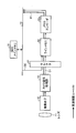
- FIG. 1 is a block diagram showing an image processing apparatus according to Embodiment 1 of the present invention.
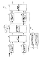
- FIG. 2 is a diagram showing a basic configuration for realizing real-time recording processing of a still image frame in Embodiment 1 of the present invention.
- FIG. 3 is a block diagram showing a first modification for realizing the real-time recording process of the still image frame according to Embodiment 1 of the present invention.
- FIG. 4 is a block diagram showing a second modification for realizing the real-time recording process of the still image frame according to Embodiment 1 of the present invention.
- FIG. 5 is a block diagram showing a third modification that realizes real-time recording processing of a still image frame according to Embodiment 1 of the present invention.
- FIG. 1 is a block diagram showing an image processing apparatus according to Embodiment 1 of the present invention.
- FIG. 2 is a diagram showing a basic configuration for realizing real-time recording processing of a still image frame in Embodiment 1 of the present invention.
- FIG. 6 is a block diagram showing a fourth modification example for realizing real-time recording processing of still image frames in Embodiment 1 of the present invention.
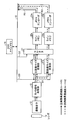
- FIG. 7 is a block diagram showing details of the image processing apparatus according to the first embodiment of the present invention.
- FIG. 8 is a block diagram showing details of the size conversion unit in the image processing apparatus according to the first embodiment of the present invention.
- FIG. 9 is a diagram showing an example in which the 8-line memory has a two-side structure.
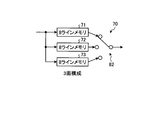
- FIG. 10 is a diagram showing an example in which the 8-line memory has a three-plane configuration.
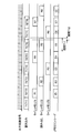
- FIG. 11 is a timing chart showing a writing period and a reading period, and a JPEG encoding period with respect to a line memory having a two-plane structure.
- FIG. 11 is a timing chart showing a writing period and a reading period, and a JPEG encoding period with respect to a line memory having a two-plane structure.
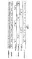
- FIG. 12 is a diagram illustrating a writing period, a reading period, and a JPEG encoding period for a three-plane line memory.
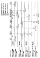
- FIG. 13 is also a diagram illustrating another example of a writing period, a reading period, and a JPEG encoding period for a line memory having a three-plane structure.
- FIG. 14 is a diagram for explaining an operation at the time of reproduction of the image processing apparatus according to the first embodiment of the present invention.
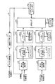
- FIG. 15 is a block diagram of an image processing apparatus according to the second embodiment of the present invention.
- FIG. 16 is a diagram for explaining control of the arbiter in the image processing apparatus according to the second embodiment of the present invention.
- the present invention is applied to an image processing apparatus capable of acquiring a still image at a high speed in parallel with acquisition of a moving image.
- the imaging apparatus as the image processing apparatus according to the present embodiment solves the problem related to the bus bandwidth of the main memory, and even when shooting still images together with moving image shooting, 10 or more images per second. High-speed shooting is possible. Furthermore, it is possible to acquire all the frames as still image frames out of the speed equivalent to the frame rate output from the normal image sensor, for example, 60 frames per second.
- FIG. 1 is a block diagram showing an imaging apparatus according to the present embodiment.
- the image capturing apparatus 1 acquires still image frames from moving image data at an arbitrary timing based on a user instruction while acquiring moving image data via an image sensor, and converts the still image frames into real time.
- the encoding (compression) processing is performed by
- real-time encoding processing refers to performing still image frame encoding processing, for example, JPEG encoding processing, at the same frame rate as the input frame rate of moving image data (camera image).
- the still image frame is described as being acquired at an arbitrary timing based on the user's instruction. For example, a “still image frame automatic acquisition mode” or the like is prepared, and a specific object such as a subject smile is prepared. A target may be automatically detected, and a still image frame may be automatically acquired according to the detection result.
- the imaging apparatus 1 includes an imaging unit including an imaging element 12 that photoelectrically converts incident light incident through the lens 11 and the lens 11 and generates image data. Furthermore, the imaging apparatus 1 includes a DDR (Double-Data-Rate) main memory 16, a moving image codec 20, a line memory 22, and a JPEG codec 23. The DDR main memory 16, the moving image codec 20, the line memory 22, and the JPEG codec 23 are connected via the bus 10.
- DDR Double-Data-Rate
- moving image data acquired by the image sensor 12 is written.
- the moving image codec 20 functions as a moving image compression unit that compresses moving image data written in the main memory.
- the moving image codec 20 further functions as a moving image expansion unit that expands compressed moving image data.
- the moving image data acquired from the image sensor 12 is once written in the DDR main memory 16 and then encoded by the moving image codec 20.
- a still image frame acquisition unit (not shown) acquires a still image frame from the moving image data acquired by the image sensor 12 at an arbitrary timing, and the still image frame is stored in the line memory 22.
- the still image data that is a part of is stored.
- the moving image data from the camera signal processing unit 13 may be stored in the line memory 22 sequentially.
- a frame acquisition unit is unnecessary.
- a still image frame is acquired at an arbitrary timing in accordance with a user instruction, for example, it is obtained from a predetermined number of still image frames from moving image data based on the timing at which the user presses a shutter button (not shown) of the imaging apparatus 1. It can be configured by a switch or the like that performs a switch operation so that still image data can be input to the line memory 22.
- the JPEG codec 23 functions as a still image compression unit that compresses still image data stored in the line memory 22.
- the JPEG codec 23 also functions as a decompression unit that decompresses compressed still image data.
- the JPEG codec 23 encodes still image data in real time in parallel with the writing of moving image data being shot to the DDR main memory 16. At this time, the DDR main memory 16 is written with the moving image data and the encoded data encoded in real time by the JPEG codec 23.
- a still image frame acquired from moving image data is directly written in real time without being written to the DDR main memory 16 and then written to the DDR main memory 16.
- the DDR main memory 16 is configured such that a still image frame (hereinafter referred to as uncompressed image data is also referred to as raw data) acquired from the captured image is encoded and then written to the DDR main memory 16 without being written.
- the load on the bus bandwidth of the bus 10 is reduced. This makes it possible to perform high-speed shooting processing of still image data having a multi-pixel image size at a speed of 60 frames per second.
- the imaging apparatus 1 further includes a camera signal processing unit 13 and a zoom / focus control unit 14 that controls the zoom magnification and focal length of the lens 11 under the control of the camera signal processing unit 13. Further, it has a CPU (Central Processing Unit) 15, an SD card (SD Memory Card) 17, and a USB (Universal Serial Bus) 18 that control each block. Furthermore, it has a size conversion unit 19, a size conversion unit 21, a video signal processing unit 24, an HDMI (High-Definition Multimedia Interface) 25, an LCD (Liquid Crystal Display) 26, and the like. Each processing unit is connected via a bus 10.
- a bus 10 10
- the camera signal processing unit 13 has a synchronization signal generation unit, a Y / C processing unit, and the like (not shown).
- the synchronization signal generation unit generates a horizontal synchronization signal and a vertical synchronization signal corresponding to the horizontal size and vertical size of the generated image data and synchronized with the internal clock.
- image data from the imaging unit image data synchronized with the horizontal synchronization signal and the vertical synchronization signal is input to the camera signal processing unit 13.
- the Y / C processing unit sequentially Y / C-processes a plurality of image data generated by the imaging unit.
- Y / C processing is processing for separating and converting image data into luminance data (Y) and color data (C). That is, the camera signal processing unit 13 outputs (moving) image data obtained by performing a series of camera signal processing such as color separation, white balance adjustment, and Y / C processing from the captured data.
- the size conversion unit 19 converts the size of the moving image data output from the camera signal processing unit 13. This moving image data is once written in the DDR main memory 16.
- the moving image codec 20 encodes moving image data once written in the DDR main memory 16 in a format conforming to, for example, the H.264 / AVC standard or the MPEG2 standard.
- the encoded data after encoding is written in the DDR main memory 16 and transferred to an external memory such as the SD card 17 as necessary. Further, at the time of reproduction, a decoding process is performed on encoded moving image data read from an external memory such as the SD card 17 and written in the DDR main memory 16, for example.
- the size conversion unit 21 converts the size of the still image frame acquired by the still image frame acquisition unit (not shown) as described above.
- the size conversion unit 19 and the size conversion unit 21 may be provided as necessary.
- the SD card 17 is a large-capacity external storage medium, and moving image data and still image data are written on the SD card 17 and can be displayed on the LCD 26.
- the image data stored in the SD card 17 is once written in the DDR main memory 16, decoded by the moving image codec 20, output to the LCD 26 via the video signal processing unit 24, or output via the HDMI 25. Can do.
- the imaging device 1 is connected to various peripheral devices via the USB 18.
- the video signal processing unit 24 performs a series of video signal processing for converting the decoded image data into output data in a format corresponding to the HDMI 25 or the LCD 26, and displays an image via the LCD 26 or a television monitor via the HDMI 25.
- the image data is output to an external monitor device.
- the imaging apparatus 1 acquires a still image frame from raw data or decoded moving image data written in the DDR main memory 16, converts the size by the size conversion unit 21, and performs line memory 22. Via the JPEG codec 23 and writing to the DDR main memory 16.
- the DDR main memory 16 decodes moving image data (first moving image data) acquired by the image sensor 12 or encoded moving image data read from an external memory such as the SD card 17 ( 2nd moving image data) is written.
- a still image frame is also acquired for the first moving image data and the second moving image data at an arbitrary timing according to a user instruction or the like, and is output to the size conversion unit 21.
- the image size of the still image frame is converted by the size conversion unit 21, a part of the still image data is sequentially written in the line memory 22, and the still image data written in the line memory 22 by the JPEG codec 23.
- the encoded data encoded in the DDR main memory 16 is output.
- a still image frame when acquiring a still image frame from raw data or decoded moving image data (first and second moving image data) written in the DDR main memory 16, not only one frame at a timing specified by the user.
- a single still image frame may be obtained by combining a plurality of neighboring frames by weighted averaging.
- the DDR main memory 16 of the imaging apparatus 1 is used when JPEG encoding is performed from the camera signal processing unit 13 without passing through the DDR main memory 16 (hereinafter also referred to as a high-speed shooting route). It is preferable to use the line memory 22 on three sides.
- JPEG encoding is performed via the DDR main memory 16 (hereinafter also referred to as “normal route”), two of the three sides of the line memory 22 are used. May be used.
- normal route two of the three sides of the line memory 22 are used. May be used.
- One of the bottlenecks at the time of the high-speed shooting route of the imaging apparatus 1 according to the first embodiment depends on the encoding processing capability of the JPEG codec 23.
- the JPEG codec 23 normally has a relationship of input data amount> encoded data amount, but depending on the complexity of the image, the amount of encoded data increases due to the allocation of Huffman codes, etc., and the above equation may be reversed. In that case, the read processing of the image data is instantaneously delayed, and the processing may fail if only two surfaces of the line memory 22 are used, and the line memory 22 needs to have a three-surface configuration.
- the still image data from the camera signal processing unit 13 is directly encoded and written to the DDR main memory 16 through the high-speed shooting route.
- the amount of data can be reduced as compared to the case where raw data is written.
- the bus bandwidth of the bus 10 of the DDR main memory 16 can be secured, and encoded still image data such as still image frames acquired 60 frames per second can be written to the DDR main memory 16. is there.
- the line memory 22 has three or more lines of memory composed of n (n is an integer of 1 or more) lines.
- n is an integer of 1 or more lines.
- the imaging apparatus 1 encodes and records a still image frame in real time at a high speed in parallel with recording of a moving image (hereinafter referred to as a still image using a high-speed shooting route).
- the processing for encoding a frame is also referred to as real-time recording processing, and the processing units that execute still image frame encoding processing in real time are collectively referred to as a still image real-time processing unit.
- a still image real-time processing unit Next, details of the real-time recording process of the still image frame will be described.
- FIG. 2 is a diagram showing a basic configuration for realizing real-time recording processing of a still image frame.
- FIGS. 3 to 16 to be described later the same components as those of the imaging apparatus 1 shown in FIG. 1 are denoted by the same reference numerals, and detailed description thereof is omitted.
- FIGS. 2 to 6 a part of the image pickup apparatus 1 is extracted and illustrated in order to explain real-time recording processing of a still image frame.
- a selector 27 is provided for switching a path (normal route) for encoding the still image frame D2 acquired from the data.
- the still image frame acquired from the moving image data acquired from the image sensor 12 is encoded in real time in the high-speed shooting route R1, the still image frame D1 is selected via the selector 27, and this is stored in the line memory 22. Input sequentially.
- the line memory 22 writes data less than one frame of still image data. Details of the line memory 22 will be described later.
- the JPEG encoder 23a arranged at the subsequent stage of the line memory 22 encodes the still image data output from the line memory 22 into the JPEG format and outputs the encoded image. This encoded data is written into the DDR main memory 16.
- the moving image data of the raw data written in the DDR main memory 16 is used.
- the moving image data is obtained by writing moving image data acquired through, for example, the lens 11 and the image sensor 12 to the DDR main memory 16.
- encoded moving image data input from an external memory such as the SD card 17 is once written in the DDR main memory 16, decoded by the moving image codec 20 shown in FIG. 1, and written again in the DDR main memory 16. Is. In either case, it is raw data or uncompressed moving image data that has been decoded.
- a still image frame is acquired at an arbitrary timing based on a user instruction and output to the size conversion unit 21.
- a route that is encoded by the JPEG codec 23 from the DDR main memory 16 via the size converter 21 and the line memory 22 is a normal route.
- the encoded still image data encoded by the JPEG codec 23 is written into the DDR main memory 16.
- FIG. 3 to 5 are block diagrams showing first to third modifications, respectively.
- the example shown in FIG. 3 which is the first modification is an example in which the size conversion unit 21 is provided in the subsequent stage of the camera signal processing unit 13 and in the previous stage of the selector 27.
- the size of the still image frame in the high-speed shooting route R1 is converted by the size conversion unit 21, so that the data capacity after encoding can be reduced.
- the user can set the still image data to be acquired to data of a desired size.
- the still image frame D2 is acquired from the DDR main memory 16, and is input to the line memory 22 via the selector 27, and is encoded by the JPEG encoder 23a.
- the still image frame D3 is obtained, and after the size conversion by the size conversion unit 21, it is input to the line memory 22 via the selector 27 and is encoded by the JPEG encoder 23a, and has two paths. That is, the user can select whether to perform size conversion.
- FIG. 4 which is a second modification example is that the size of the still image frame acquired from the moving image data input via the camera signal processing unit 13 is converted in real time to the main image data and Each has a main image size conversion unit 21a and a sub image size conversion unit 21b for generating sub image data.
- line memories 22a and 22b and JPEG encoders 23a and 23b are provided corresponding to the main image size conversion unit 21a and the sub image size conversion unit 21b, respectively.
- the operations of the line memories 22a and 22b are the same as those of the line memory 22, and the operation of the JPEG encoder 23b is the same as that of the JPEG encoder 23a.
- the selector 27 converts the still image frame D1 acquired from the moving image data from the camera signal processing unit 13 into the main image size by the main image size conversion unit 21a, and the still image frame D1 is the sub image size.
- the raw data written in the DDR main memory 16 or the still image frame D2 obtained from the decoded moving image data, or the raw data of the DDR main memory 16 either the still image data obtained by converting the size of the still image frame D3 acquired from the decoded moving image data by the main image size converting unit 21a or the sub image size converting unit 21b is selected, and the line memory 22a or the line memory is selected. To 22b.
- the main image size conversion unit 21a, the line memory 22a, and the JPEG encoder 23a can perform real-time encoding processing of still image data of the main image size.
- a route in which the real-time encoding process is performed and the encoded data is written in the DDR main memory 16 is defined as a main image high-speed shooting route R1.
- This main image high-speed shooting route corresponds to the high-speed shooting route shown in FIG.
- the sub-image size conversion unit 21b, the line memory 22b, and the JPEG encoder 23b can perform real-time encoding processing of still image data having a sub-image size such as a thumbnail.
- a route in which the real-time encoding process is performed and the encoded data is written in the DDR main memory 16 is set as a sub-image high-speed shooting route R2.
- a still image frame is acquired in real time by the main image high-speed shooting route R1 or the sub-image high-speed shooting route R2, and is converted into still image compressed data, and is written in the DDR main memory 16.
- the data amount is about 1/3 of the original image size. Therefore, as in the first embodiment and the first modification described above, the load on the bus band of the bus 10 of the DDR main memory 16 is reduced, and thus high-speed still image shooting is possible.
- JPEG files of various sizes desired by the user can be encoded in the same processing time when not reduced.
- EXIF package processing can be realized at higher speed by performing parallel processing (reduction and transfer to the main memory) of the index sub-image (thumbnail) with the main image data in real time.
- the line memory necessary for the reduction processing can be shared between the main image data and the thumbnail data depending on the circuit configuration.
- the selector 27 selects the still image data (D1) from the main image high-speed shooting route R1 and the still image frame D3 acquired from the raw data or the decoded moving image data written in the DDR main memory 16 according to the mode. Select one of them.
- the still image data selected and output by the selector 27 is input to the line memory 22a, then input to the JPEG encoder 23a, encoded, and written to the DDR main memory 16.
- the sub image size converting unit 21d connected in series to the main image size converting unit 21c is provided.
- the main image size is larger than the sub-image size. Therefore, first, the size conversion of the still image frame whose size is converted by the main image size conversion unit 21c by the sub-image size conversion unit 21d is larger than the size conversion of the still image frame D1 acquired from the moving image data. Is small. Therefore, in the present modification, still image frames are converted by the sub-image size conversion unit 21d using the result of the main image size conversion unit 21c. Thereby, the amount of calculation processing in the sub-image size conversion unit 21d can be reduced.
- the line memory (scaler buffer 212a / b) used in the vertical filter circuit is necessary.
- the number of lines increases. Therefore, by devising the system configuration, if the filter processing that pre-filters the main image image data and writes it to the line memory, and additionally reduces the frequency characteristics of the thumbnail image data, The line memory resources of the remaining thumbnail image data can be allocated to other locations.
- the sub-image high-speed shooting route R2 does not have a JPEG codec. This is because the sub image data is smaller than the main image data, and the data capacity is not so large. Therefore, it is possible to write to the DDR main memory 16 as uncompressed data without performing encoding processing in real time.
- FIG. 6 relates to a fourth modification of the basic configuration shown in FIG. 2, and also shows a shooting route R3 for moving image data. Compared with the imaging apparatus 1 in FIG. 1, the difference is that the size conversion unit 19 is not provided. Other configurations are the same as those of the imaging apparatus 1 shown in FIG. In the moving image shooting route R3, the moving image data from the camera signal processing unit 13 is once written in the DDR main memory 16. Thereafter, the moving image data is converted into, for example, H.264 by the moving image encoder 20a. The encoded data conforms to the H.264 / AVC standard or MPEG2 standard, and is written back to the DDR main memory 16.
- FIG. 7 is a diagram showing blocks related to the high-speed shooting route and the moving image shooting route between the camera signal processing unit 13 and the DDR main memory 16.
- the imaging apparatus 1 has two paths for encoding still image frames acquired from moving image data output from the camera signal processing unit 13.
- One is a path related to still image data serving as a main image (hereinafter referred to as path 1), and the other is a path related to still image data serving as a sub image (thumbnail) (hereinafter referred to as path 2).
- the path 1 includes a first input image selection unit 28, a main image size conversion unit 21a, and a line memory 22a.
- the still image data from the line memory 22a is input to the JPEG core 23c and encoded in real time.
- the path 2 includes a second input image selection unit 29, a sub-image size conversion unit 21b, and a line memory 22b, and still image data from the line memory 22b is input to the JPEG core 23c and encoded in real time.
- the still image data in the path 2 does not have to be encoded in real time, and may be temporarily written in the DDR main memory 16a.
- the main image size conversion unit 21a includes a size conversion unit 211a and a scaler buffer 212a
- the sub-image size conversion unit 21b includes a size conversion unit 211b and a scaler buffer 212b.
- the scaler buffers 212a and 212b are line memories.
- the main image size conversion unit 21a and the sub image size conversion unit 21b basically convert still image data input from the camera signal processing unit 13 into sizes for main images and thumbnails, respectively. Details of the main image size conversion unit 21a and the sub image size conversion unit 21b will be described later.
- the line memory 22a has a memory controller 221a and a buffer 222a composed of SRAM, etc.
- the line memory 22b has a memory controller 221b and a buffer 222b.
- the buffers 222a and 222b are three-surface and two-surface buffers, respectively.
- the JPEG core 23c is also connected with, for example, a two-sided buffer 231.
- the buffers 222a and 222b are made of SRAM, for example, and their functions will be described later.
- the memory controllers 221a and 221b control data access to the buffers 222a and 222b in order to make the SRAM function as a line memory, for example. Further, when the main image size conversion unit 21a, the sub image size conversion unit 21b, and the JPEG core 23c have different clock frequencies, processing for converting the clock frequency can be performed.
- the JPEG core 23c has a JPEG codec and an interface. When there is no encoding, the JPEG core 23c transfers the main image YUV data for the main image and the thumbnail YUV data for the thumbnail to the DDR main memory 16a. When encoding is performed, the main image data is encoded and the stream is transferred to the DDR main memory 16a. As for the thumbnail image, the thumbnail image data is encoded and the stream is transferred to the DDR main memory 16a.
- the DDR main memory 16a in this example also includes a DDR interface.
- the first input image selection unit 28 and the second input image selection unit 29 have the function of the selector 27 shown in FIGS. 2 to 6 for selecting input image data from a plurality of routes.
- a still image frame acquired from raw moving image data from the DDR main memory 16a or decoded moving image data is selected during normal moving image shooting. Further, when shooting a still image during moving image shooting, a still image frame from the high-speed shooting route is selected.
- a moving image reproduction route that is, an input still image frame acquired from raw moving image data or decoded moving image data written in the DDR main memory 16a is selected.
- still image frames acquired from the moving image data from the camera signal processing unit 13 or the moving image data from the DDR main memory 16a are for main images and thumbnails, respectively. Is converted to the size of
- the still image frames subjected to the size conversion in the horizontal direction and the vertical direction are respectively stored in the buffers 222a and 222b controlled by the memory controllers 221a and 221b.
- the buffers 222a and 222b constituting the line memories 22a and 22b are buffers for 8 lines for storing pixels necessary for 8 ⁇ 8 DCT, Y8 line x 3 surfaces + C8 line x 3 surfaces (in the case of format 4: 2: 2) Y16 line x 3 planes + C8 line x 3 planes (when image format is 4: 2: 0) It becomes the composition of.
- the number of faces is for single port.
- the buffer 231 may have a SRAM 2 surface configuration or the like.
- the capacity varies depending on the system configuration, and it is only necessary to absorb the delay when the writing process for writing the transfer data to the DDR main memory 16a is stagnant.
- FIG. 8 is a block diagram showing details of the size converter 21. It has a two-channel configuration according to the acquired still image data. Thus, data can be processed even when two lines (progressive ODD (odd number), EVEN (even number)) are input simultaneously. By using two channels simultaneously, the processing clock rate of camera processing can be lowered.
- the input image is limited to the required frequency characteristics by the horizontal filter circuit (ch1) 41 and the horizontal filter circuit (ch2) 42.
- the sampling frequency is thinned out from horizontal 1024 pixels ⁇ vertical 768 lines of fs to 512 pixels ⁇ 384 lines
- filtering is performed by setting the cutoff frequency of the filter to be fs / 4.
- the pixel is thinned to 512 pixels by the horizontal thinning circuit 43 and written to the scaler buffer 212a.
- moire folding distortion
- the scaler processing line memory controller 44 adjusts the scale of the image data thinned out by the horizontal thinning circuit 43. Specifically, with respect to the data after thinning, when the sample point is between the sampling points, a value is obtained by calculating according to the distance of the sample after interpolation from two samples of the filtered image signal, and a straight line between the pixels Perform interpolation etc.
- the still image frame after horizontal interpolation is output to the vertical filter circuits 45 and 46.
- the vertical filter circuits 45 and 46 filter the still image data read from the line memory (scaler buffer 212a) in the vertical direction. After filtering, vertical thinning is performed by the vertical thinning circuit 47, and only necessary image data is written into the buffers 222a and 222b via the memory controllers 221a and 221b at the subsequent stages.
- the size conversion can be independently performed in parallel on the main image and the thumbnail image. It is also possible to reduce the buffer size by sharing the scaler buffer 212a. For example, consider a case where the main image still image data is set to fs / 4 by frequency characteristic reduction processing in the horizontal filter circuits 41 and 42. In the filter processing in the thumbnail horizontal filter circuits 48 and 49 connected in series in the subsequent stage, the horizontal 160 pixels ⁇ vertical 120 lines are used.
- Size converter 211a only (each independently used): fs / 12.8 processing required Size converter 211a + 211b Scaler 1 + Scaler 2 (connected in series in the subsequent stage): fs / 6.4 treatment (because fs / 2 ⁇ fs / 4 in the previous stage)
- the frequency characteristic limit width can be reduced by connecting to the subsequent stage in series.
- the limit width is small, the band order efficiency is good and the image quality is merited if the order is the same.
- the image quality is comparable, the order can be reduced.
- the necessary line memory of the scaler buffer 212b is reduced, and the surplus line memory can be allocated to other resources.
- thumbnail size converter signals between the vertical filter circuits 45 and 46 and the vertical thinning circuit 47 are used. That is, the size conversion of the still image data after the size conversion by the size conversion unit for the main image is performed.
- the thumbnail size converter also has horizontal filter circuits 48 and 49, a horizontal thinning circuit, a scaler processing line memory controller, a vertical filter circuit, and a vertical thinning circuit, and outputs a still image image whose size has been converted by the same processing. To do.
- the still image data written in the buffers 222a and 222b is transferred to the DDR main memory 16a every time it is written as, for example, 8-line data.
- the processing on the DDR main memory 16a side varies depending on the system, but it is normal to write still image routes, moving image routes, and other calculation results for camera control signals into the DDR main memory 16a. Therefore, a band capable of processing a rate higher than the data rate of the real-time recording process of the still image frame is secured. However, there may be a moment when the bus bandwidth of the bus 10 is occupied by data other than the real-time recording process of the still image frame. Therefore, the imaging apparatus includes scaler buffers 212a and 212b, buffers 222a and 222b, a stream buffer 231 and the like in order to absorb the processing delay of the DDR main memory 16a.
- FIG. 9 is a diagram showing an example in which the 8-line memory has a two-side configuration
- FIG. 10 is a diagram showing an example in which the 8-line memory has a three-side configuration.
- the 8-line memories 51 and 52 are switched by the switch 61.
- the 8-line memories 71 to 73 are switched by the switch 82.
- FIG. 11 is a timing chart showing a writing period and a reading period to the line memory 50, and a JPEG encoding period. Writing to the line memory 50 is performed continuously for 8 horizontal synchronization periods (T1 to T8), and reading is almost equal to the timing at which the JPEG encoder encodes data for 8 lines.
- the amount of computation required for processing varies depending on the input image data.
- the compression rate is 1 or less and the encoding process is a processing period of 8 lines or less.
- the compression rate is 1 or more and the processing period is 8 lines or more. There is.
- FIG. 12 is a diagram showing a writing period, a reading period, and a JPEG encoding period with respect to the line memory 70 having the three-surface configuration.
- the period R5 for reading the line memory 72 is longer than 8 lines, even when the encoding period of the JPEG encoder is a period T11 in which the input image is a complex picture and the processing period is 8 lines or more.
- the line memory to be written is the line memory 71 (T7), a period in which the timings overlap in the same line memory does not occur, and JPEG encoding can be performed correctly.
- some line memories can function as a buffer that absorbs fluctuations in the processing rate during real-time processing of still image frames.
- this line memory can also function as a buffer for adjusting the timing when compressed data after compression processing is written to the DDR main memory 16.
- FIG. 13 is also a diagram illustrating another example of a writing period, a reading period, and a JPEG encoding period with respect to the line memory 70 having a three-surface configuration.
- a period indicated by a period T ⁇ b> 13 indicates a period during which other blocks are permitted to output to the bus 10 and the JPEG codec 23 cannot output a JPEG stream to the bus 10.
- the JPEG codec 23 accumulates the JPEG encoded stream in a buffer provided in the output stage until output is permitted. If the JPEG encoded stream is output from the buffer to the bus 10 of the DDR main memory 16a after the output is permitted, the operation can be performed without interrupting the JPEG stream.
- the JPEG stream will be interrupted, so the buffer capacity needs to have a large margin.
- the 8-line memory of the line memory 22 it is possible to prevent the output buffer capacity of the DDR main memory 16 from becoming insufficient.
- the read timing from the 8-line memory of the line memory 22 is delayed until the output to the bus 10 of the DDR main memory 16a becomes possible (R4), and the start of JPEG encoding is delayed, whereby the JPEG stream is transferred to the DDR main memory.
- the transfer timing to 16a can be delayed.
- the ratio of the JPEG stream is large. However, in actuality, such a timing is obtained in a state where the size conversion output for moving images, the moving image codec, and video processing are combined. Will occur.
- the output stage to the bus 10 of the DDR main memory 16a of each block has a buffer to cope with the fact that the bus cannot be output.
- the 8-line memory of the line memory 22 in the preceding stage of the JPEG codec 23 can also have the same role as a buffer for adjusting the bus output.
- FIG. 14 is a diagram for explaining the operation during reproduction of the imaging apparatus.
- encoded encoded moving image data written in the DDR main memory 16 is input to the moving image decoder 20b, decoded, and written into the DDR main memory 16.
- the decoded moving image data is subjected to video signal processing by the video signal processing unit 24 and output to the LCD 26 and the HDMI 25.
- the user can press the shutter at any timing.
- a still image frame corresponding to the shutter timing is acquired, input to the JPEG encoder 23 a via the selector 27, encoded, and written to the DDR main memory 16.
- one still image frame may be generated by averaging or weighted averaging from two or more frames.
- a still image frame acquired from moving image data being shot is directly encoded in real time without being written into the main memory, so that a minimum circuit scale, a minimum operation clock, and a minimum associated with it are recorded.
- realizing power consumption even with a multi-pixel image size, it is possible to realize high-speed shooting processing with a larger number of images, for example, 60 frames per second.
- still image acquisition processing while performing moving image acquisition processing is systematic. Therefore, in order to realize this, there are disadvantages and limitations such as an increase in cost, an increase in the difficulty of LSI generation such as an increase in bus clock frequency, an increase in power consumption, and a reduction in the video processing rate.
- the efficiency of still image processing can be improved, and high-speed still image acquisition processing can be executed without affecting the moving image acquisition processing. That is, still image capture can be realized with high speed and high efficiency even when reproducing a moving image with the minimum necessary configuration.
- FIG. 15 is a block diagram illustrating the imaging apparatus according to the present embodiment.
- a still image frame acquisition unit 94 is provided in the imaging apparatus 1a according to the present embodiment.
- all the data may be sequentially sent to the size converter 21, the line memory 22, and the JPEG codec 23. In particular, it is not necessary to provide the still image frame acquisition unit 94.
- Image data of a predetermined frame flows from the moving image data output from the signal processing unit 13 or the decoded moving image data written in the DDR main memory 16 to the size conversion unit 21 side.
- the DDR main memory is used when moving image data is written into the DDR main memory 16, and when encoded data from the JPEG codec 23 is written into the DDR main memory 16.
- a plurality of timing adjustment buffers 91 to 93 for arbitrating use of the 16 buses 10 are provided.
- an arbiter 95 that functions as an arbitration unit that controls the plurality of timing adjustment buffers 91 to 93 is provided. Still image data passing through the high-speed shooting route R1 is encoded and written to the DDR main memory 16, but at a certain timing, the bus bandwidth of the bus 10 of the DDR main memory 16 may be insufficient. It may be necessary to perform arbitration using a plurality of timing adjustment buffers 91 to 93.
- timing adjustment buffers 91 to 93 are shown here, it goes without saying that the SD card 17 and the video signal processing unit 24 may be provided with timing adjustment buffers as necessary.
- FIG. 16 is a diagram for explaining the control of the arbiter 95.
- the arbiter 95 writes data to the DDR main memory 16 after the size conversion of the moving image data size conversion unit 19 (A), reads from the DDR main memory 16 of the video codec 20 (B), A case will be described in which the writing (C) of the moving image codec 20 to the DDR main memory 16 and the writing (D) operation of the encoded data of the JPEG codec 23 to the DDR main memory 16 are arbitrated.
- FIG. 16 shows a request signal for transmitting an access request to the DDR main memory 16 of the JPEG codec 23 to the arbiter 95 when the size converter 19 and the video codec 20 are read, when the video codec 20 is written, and when access is not permitted.
- the wait signal received from the arbiter 95 is shown in FIG.
- the arbiter 95 permits access if no other request signal is received and the bus bandwidth of the bus 10 of the DDR main memory 16 is free.
- the arbiter 95 when the arbiter 95 receives a plurality of request signals, for example, at timing T21, a video codec read request signal of priority 3 and a video codec write request signal of priority 4 are output. In this case, the arbiter 95 outputs a moving image codec light wait signal, stops the moving image codec light, and executes a priority 3 moving image codec read process.
- the size conversion unit 19 having the priority 2 outputs the request signal.
- a request signal is output from the JPEG codec 23 having a higher priority than the priority 1. Therefore, since the size conversion unit 19 has a lower priority than the JPEG codec 23, the size conversion unit 19 is again in the wait state, and the write operation of the size conversion unit 19 is permitted at the timing T24 when the write operation of the JPEG codec 23 is completed.
- the imaging apparatus 1a directly encodes a still image frame in real time without writing it to the DDR main memory 16 so as to enable high-speed still image shooting during moving image shooting.
- the load on the bus bandwidth of the bus 10 of the DDR main memory 16 can be reduced as compared with the conventional route in which the raw data of the still image frame is once written in the DDR main memory 16 and then encoded. As a result, high-speed still image shooting is possible.
- a still image frame is encoded in real time without being written to the DDR main memory 16 and then written to the DDR main memory 16, for example, a moving image consisting of 60 frames per second. Still image frames can be acquired for all frames of data.
- the memory bandwidth of the DDR main memory 16 may be insufficient. Even in such a case, the processing to the DDR main memory 16 is delayed by providing the timing adjustment buffers 91 to 93 and the like and performing arbitration of the bus 10 by the arbiter 95 as in the present embodiment. Can be implemented without.
- the timing adjustment buffer 91 is provided for adjusting the timing when the bus bandwidth of the DDR main memory 16 of the JPEG codec 23 is used.
- the JPEG codec 23 according to the present embodiment is ,
- An 8-line memory has a three-surface configuration. Therefore, a part of this line memory may be used instead of the timing adjustment buffer 91.
- the present embodiment it is possible to provide an imaging device capable of high-efficiency processing, high-speed processing, and cost reduction in still image shooting.
- efficient still image processing enables high-speed still image processing at a lower cost.
- Non-transitory computer readable media include various types of tangible storage media.
- non-transitory computer-readable media are magnetic recording media (eg flexible disks, magnetic tapes, hard disk drives), magneto-optical recording media (eg magneto-optical disks), CD-ROM (Read Only Memory), CD-R, Includes CD-R / W, semiconductor memory (for example, mask ROM, PROM (Programmable ROM), EPROM (Erasable PROM), flash ROM, RAM (random access memory)).
- the program may be supplied to the computer by various types of temporary computer readable media.
- Examples of transitory computer readable media include electrical signals, optical signals, and electromagnetic waves.
- the temporary computer-readable medium can supply the program to the computer via a wired communication path such as an electric wire and an optical fiber, or a wireless communication path.
Landscapes
- Engineering & Computer Science (AREA)
- Multimedia (AREA)
- Signal Processing (AREA)
- Computing Systems (AREA)
- Theoretical Computer Science (AREA)
- Studio Devices (AREA)
- Television Signal Processing For Recording (AREA)
Abstract
動画撮影と並行して、高速に静止画データをエンコードしてメインメモリに格納する。撮像装置(1)は、動画像データを格納するDDRメインメモリ(16)と、メインメモリ(16)に格納された動画像データをエンコードする動画コーデック(20)と、撮像素子(12)により取得された動画像データから任意のタイミングで静止画フレームを取得する静止画フレーム取得部と、その静止画フレームの一部である静止画データを格納するラインメモリ(22)と、動画像データのメインメモリ(16)への格納と並行してリアルタイムで静止画データをエンコードするJPEGコーデック(23)とを有し、メインメモリ(16)は、動画像データを格納すると共に、JPEGコーデック(23)によりリアルタイムでエンコードされたエンコードデータを格納する。
Description
本発明は、動画撮影中に静止画を撮影する機能を有する画像処理装置、画像処理方法、及びプログラムに関し、特に、高速にリアルタイムにエンコードした静止画データを取得するのに好適な画像処理装置、画像処理方法、及びプログラムに関する。
デジタルカメラ又はデジタルビデオカメラ等で、動画撮影と共に静止画を撮影する機能を有する従来の撮像装置においては、静止画のみの撮影を行う撮像装置と同様、静止画を撮影しファイル化する際、画像データを非圧縮のファイルで保存したり、JPEG(Joint Photographic Experts Group)形式等の圧縮データにして保存するのが一般的である。それらファイル化の際、通常、撮像素子同等の解像度を有するメインの画像のほかにサムネイルと呼ばれるインデックス用の副画像(水平160画素×垂直120画素)を同時にファイルにパッケージする。これにより、副画像を、静止画再生時に画像サイズの小さいインデックス用の画像としてサムネイルに表示し、ユーザが静止画を確認して効率よく選択することができる。これはデジタルカメラ用の画像ファイル規格であるEXIF(Exchangeable Image File Format)等に規定されている。
ところで、動画撮影と共に静止画を撮影する機能を有する従来の撮像装置として例えば特許文献1に記載の電子カメラが公知である。この特許文献1には、静止画の撮影可能枚数に内部メモリによる制限が生じないようにし、撮像される動画に不連続部分があっても再生時にユーザに違和感を与えないように記録することを目的とした電子カメラが開示されている。
この特許文献1に記載の電子カメラにおいては、動画記録中に静止画記録要求の指示が与えられた場合、静止画記録要求に呼応して静止画撮影画像を記憶手段に記憶するとともに所定時間の間、記憶手段に撮像素子からの画像の取り込みを禁止し、この間に記憶手段の画像を繰り返し読み出すことにより、静止画撮影画像を動画として動画記録部に記録する。また、静止画撮影画像の動画処理の合間に記憶手段に格納されている静止画撮影画像を静止画として静止画記録部に記録する静止画処理を実行し、静止画撮影画像を静止画として静止画記録部に記録し終えた時又はその後に所定時間が満了することにより、禁止が解除されて撮像素子から得られる画像を動画として動画記録部に記録する記録動作を再開させるものである。
上述の特許文献1を含む従来の撮像装置においては、通常、静止画撮影をする際には、撮像素子等を介して取得された画像データを一度メインメモリに格納し、画質補正等を行った後にJPEG等の形式で圧縮して主画像ストリームを生成する。更に、必要に応じてメインメモリの画像をサムネイル用のサイズにサイズ変換してJPEG等の形式で圧縮してサムネイル用のストリームを生成する。そして、これらをEXIFとしてパッケージすることで一般的なJPEGファイルが生成される。この一連の処理(以下、静止画エンコード処理という。)においては、
(1)メインメモリへの画像データの書き込み処理
(2)メインメモリから画像データを読み出しながら、読み出された画像データをJPEG形式へエンコード処理
(3)エンコード処理されたデータのメインメモリへのストリームの書き込み処理等の処理によりメインメモリに対するアクセスが多数発生するため、メモリバス帯域を圧迫する。このため、メモリ処理クロック周波数を高くしたりバス幅を広げたりする必要が生じ、結果、コストが高くなったり、消費電力が増加する等の問題点があった。
(1)メインメモリへの画像データの書き込み処理
(2)メインメモリから画像データを読み出しながら、読み出された画像データをJPEG形式へエンコード処理
(3)エンコード処理されたデータのメインメモリへのストリームの書き込み処理等の処理によりメインメモリに対するアクセスが多数発生するため、メモリバス帯域を圧迫する。このため、メモリ処理クロック周波数を高くしたりバス幅を広げたりする必要が生じ、結果、コストが高くなったり、消費電力が増加する等の問題点があった。
高速に静止画エンコード処理を行なおうとすると上記問題点が顕著となる。特に動画撮影と共に静止画撮影をする場合、撮像素子から取得された動画像データをメインメモリに書き込むのと同時に、静止画データをメインメモリに書き込み、エンコードして再度メインメモリへ書き込むという一連の静止画エンコード処理が必要となるが、この場合、動画像データをメインメモリに書き込む処理と静止画データをメインメモリに書き込む処理を同時に行うと、メモリのバス帯域が不足するため、高速に静止画データを取得することが不可能となる。
すなわち、従来の撮像装置のように、フレームメモリに静止画データを書き込んでから静止画エンコード処理を動画撮影に伴う処理と同時に行なう場合は、フレームメモリのバス帯域が不足するため、同一フレーム期間に書き込みと読み出しを同時に行うことができない。このため、約10枚以上ないし全フレームの静止画エンコード処理が不可能となり、例えば1秒60フレームからなる動画像において、60フレームのうち処理可能な数枚のフレームを選択してJPEGファイル化を行わなければならないという問題点があった。
また、ユーザが主画像サイズとして、撮像素子から出力されるサイズではなく1/2や1/3などの縮小サイズを望む場合、更に主画像のリサイズ処理のために時間がかかり高速な静止画処理ができなくなる。
本発明は、このような問題点を解決するためになされたものであり、動画撮影と並行して、高速に静止画データをリアルタイムにエンコードしてメインメモリに格納することが可能な画像処理装置、画像処理方法、及びプログラムを提供することを目的とする。
本発明にかかる画像処理装置は、撮像素子と、前記撮像素子により取得された動画像データを格納するメインメモリと、前記メインメモリに格納された動画像データを圧縮処理する動画圧縮部と、前記撮像素子により取得された動画像データから任意のタイミングで静止画フレームを取得する静止画フレーム取得部と、前記静止画フレーム取得部により取得された静止画フレームの一部である静止画データを格納するラインメモリと、前記ラインメモリに格納された静止画データを圧縮処理する静止画圧縮部とを有し、前記静止画圧縮部は、前記動画像データの前記メインメモリへの格納と並行してリアルタイムで前記静止画データを圧縮処理し、前記メインメモリは、前記動画像データを格納すると共に、前記静止画圧縮部によりリアルタイムで圧縮処理された圧縮データを格納するものである。
また、前記画像処理装置はタイミング調整用バッファをさらに有し、前記タイミング調整用バッファは、前記動画像データが前記メインメモリへ格納される際のタイミングと、前記静止画圧縮部によりリアルタイムで圧縮処理された圧縮データが前記メインメモリへ格納される際のタイミングとを調整することができる。
さらに、前記ラインメモリは、3面以上のn(nは1以上の整数)ラインからなるメモリから構成され、前記メモリの一部は、前記静止画圧縮部による前記静止画データの圧縮処理における処理レートの変動を吸収するバッファとして機能すると共に、圧縮処理後の圧縮データが前記メインメモリへ格納される際のタイミングを調整するバッファとして機能させることができ、ラインメモリを3面以上有することで、圧縮後のデータをメインメモリに格納する際等のタイミングを制御することができる。
さらにまた、前記画像処理装置はサイズ変換部をさらに有し、前記サイズ変換部は前記静止画フレーム取得部により取得された静止画フレームのサイズをリアルタイムに変換することができる。
また、前記画像処理装置は主画像サイズ変換部及び副画像サイズ変換部をさらに有し、前記主画像サイズ変換部は前記静止画フレーム取得部により取得された静止画フレームのサイズをリアルタイムに変換して主画像データを生成し、前記副画像サイズ変換部は前記静止画フレーム取得部により取得された静止画フレームのサイズをリアルタイムに変換して副画像データを生成するものとすることができ、主画像と共に副画像サイズの画像を取得することができる。
また、前記副画像サイズ変換部は、前記主画像サイズ変換部が生成した前記主画像データのサイズをリアルタイムに変換して副画像データを生成することができ、主画像サイズに縮小されたデータを使用して副画像データを生成するため、副画像サイズ変換処理を軽くすることができる。
さらに、前記ラインメモリは、前記主画像サイズ変換部により生成された主画像データの一部を格納し、前記静止画圧縮部は、前記動画像データの前記メインメモリへの格納と並行してリアルタイムで前記主画像データを圧縮処理し、前記副画像サイズ変換部が生成した副画像データは圧縮処理することなく前記メインメモリに格納するものとすることができ、副画像データは容量が小さいため、リアルタイムで圧縮しなくてもよい。
さらにまた、前記サイズ変換部はサイズ変換用ラインメモリを備え、前記サイズ変換用ラインメモリは、前記静止画フレーム、前記主画像データ又は前記副画像データの一部を格納するラインメモリを有することができ、サイズ変換部からの出力タイミングを調整する等することができる。
また、前記画像処理装置は動画像用サイズ変換部をさらに有し、前記動画像用サイズ変換部は前記撮像素子により取得された動画像データのサイズを変換し、前記メインメモリは、前記動画像用サイズ変換部によりサイズ変換された動画像データを格納することができ、動画像データのサイズを変換することも可能である。
さらに、前記メインメモリは、外部メモリから読み込まれた圧縮動画像データが伸長された動画像データを格納し、前記ラインメモリは、前記メインメモリに格納された、前記撮像素子により取得された動画像データ、又は前記伸長された動画像データの何れかから任意のタイミングで取得した静止画フレームの一部である静止画データを格納し、前記静止画圧縮部は、前記ラインメモリに格納された前記静止画データの圧縮処理を行うことができ、メインメモリに格納されている非圧縮の動画像データから静止画フレームを取得し、その圧縮データを生成することができる。
本発明にかかる画像処理方法は、撮像素子により取得された動画像データをメインメモリに格納する動画像格納工程と、前記撮像素子により取得された動画像データから任意のタイミングで取得された静止画フレームの一部である静止画データをラインメモリに格納するラインメモリ格納工程と、前記ラインメモリに格納された前記静止画データに対しリアルタイムで圧縮処理を行う静止画圧縮工程と、前記ラインメモリ格納工程、前記静止画圧縮工程又は前記静止画格納工程と並行して前記撮像素子により取得された動画像データをメインメモリに格納する動画像格納工程とを含むものである。
本発明にかかるプログラムは、動画像の記録処理と並行して静止画像の記録処理をコンピュータに実行させるためのプログラムであって、撮像素子により取得された動画像データをメインメモリに格納する動画像格納処理と、前記撮像素子により取得された動画像データから任意のタイミングで取得された静止画フレームの一部である静止画データをラインメモリに格納するラインメモリ格納処理と、前記ラインメモリに格納された前記静止画データに対しリアルタイムで圧縮処理を行う静止画圧縮処理と、前記静止画圧縮処理にてリアルタイムに圧縮処理された圧縮データを前記メインメモリに格納する静止画格納処理と、前記ラインメモリ格納処理、前記静止画圧縮処理又は前記静止画格納処理と並行して、前記撮像素子により取得された動画像データをメインメモリに格納する動画像格納処理とをコンピュータに実行させるためのプログラムである。
本発明によれば、動画撮影と並行して、高速に静止画データをリアルタイムにエンコードしてメインメモリに格納することが可能な画像処理装置、画像処理方法、及びプログラムを提供することができる。
以下、本発明を適用した具体的な実施の形態について、図面を参照しながら詳細に説明する。この実施の形態は、本発明を、動画像の取得と並列して高速に静止画像を取得することができる画像処理装置に適用したものである。
上述したように、動画撮影と共に静止画撮影をする場合、従来は、メインメモリのバス帯域が不足するため、1秒間60フレームとしても、せいぜい数枚乃至10枚の静止画フレームを取得することしかできない。これに対し、本実施の形態にかかる画像処理装置としての撮像装置は、メインメモリの上記バス帯域に関する問題を解決するため、動画撮影と共に静止画撮影をする場合であっても、毎秒10枚以上の高速撮影が可能である。さらには、通常撮像素子から出力されるフレームレート同等の速度、例えば毎秒60フレームのうち、全フレームを静止画フレームとして取得することができるものである。
<本発明の実施の形態1.>
図1は、本実施の形態にかかる撮像装置を示すブロック図である。本実施の形態にかかる撮像装置1は、撮像素子を介して動画像データを取得しつつ、ユーザの指示に基づく任意のタイミングで動画像データから静止画フレームを取得し、その静止画フレームをリアルタイムでエンコード(圧縮)処理を行うものである。ここで、リアルタイムでのエンコード処理とは、動画像データ(カメラ画像)の入力フレームレートと同じフレームレートで静止画フレームのエンコード処理、例えばJPEGエンコード処理を行うことをいう。また、以下では、静止画フレームは、ユーザの指示に基づく任意のタイミングで取得されるものとして説明するが、例えば、「静止画フレーム自動取得モード」等を用意し、被写体の笑顔等、特定の対象を自動で検知し、当該検知結果に応じて自動で静止画フレームを取得するようにしてもよい。
図1は、本実施の形態にかかる撮像装置を示すブロック図である。本実施の形態にかかる撮像装置1は、撮像素子を介して動画像データを取得しつつ、ユーザの指示に基づく任意のタイミングで動画像データから静止画フレームを取得し、その静止画フレームをリアルタイムでエンコード(圧縮)処理を行うものである。ここで、リアルタイムでのエンコード処理とは、動画像データ(カメラ画像)の入力フレームレートと同じフレームレートで静止画フレームのエンコード処理、例えばJPEGエンコード処理を行うことをいう。また、以下では、静止画フレームは、ユーザの指示に基づく任意のタイミングで取得されるものとして説明するが、例えば、「静止画フレーム自動取得モード」等を用意し、被写体の笑顔等、特定の対象を自動で検知し、当該検知結果に応じて自動で静止画フレームを取得するようにしてもよい。
上記動作を実現するため、撮像装置1は、レンズ11及びレンズ11を通じて入射した入射光を光電変換し画像データを生成する撮像素子12等からなる撮像部を有する。さらに、撮像装置1は、DDR(Double-Data-Rate)メインメモリ16、動画コーデック20、ラインメモリ22、及びJPEGコーデック23を有している。これらDDRメインメモリ16、動画コーデック20、ラインメモリ22、及びJPEGコーデック23は、それぞれバス10を介して接続される。
DDRメインメモリ16には、撮像素子12により取得された動画像データが書き込まれる。動画コーデック20は、メインメモリに書き込まれた動画像データを圧縮処理する動画圧縮部として機能する。動画コーデック20は、さらに、圧縮された動画像データを伸張する動画像伸張部としても機能する。撮像素子12から取得された動画像データは一旦DDRメインメモリ16に書き込みされその後、動画コーデック20によりエンコード処理される。
一方、静止画の方は、静止画フレーム取得部(図示せず)により、撮像素子12で取得された動画像データから任意のタイミングで静止画フレームを取得し、ラインメモリ22にその静止画フレームの一部である静止画データを格納する。なお、例えば1秒間に60フレームからなる動画像データの60フレーム全部を静止画データとして取得する場合は、カメラ信号処理部13からの動画像データを順次ラインメモリ22に格納すればよく、静止画フレーム取得部は不要である。また、ユーザの指示により任意のタイミングで静止画フレームを取得する場合は、例えばユーザが撮像装置1の図示しないシャッタボタンを押下したタイミングに基づき、動画像データから所定枚数の静止画フレームから得られる静止画データをラインメモリ22に入力できるようにスイッチ動作するスイッチ等により構成することができる。
また、JPEGコーデック23は、ラインメモリ22に格納された静止画データを圧縮処理する静止画圧縮部として機能する。JPEGコーデック23は、圧縮された静止画データを伸張する伸張部としても機能する。このJPEGコーデック23は、撮影中の動画像データのDDRメインメモリ16への書き込みと並行してリアルタイムで静止画データをエンコード処理する。このとき、DDRメインメモリ16は、動画像データが書き込まれると共に、JPEGコーデック23によりリアルタイムでエンコード処理されたエンコードデータが書き込まれる。
このように構成された撮像装置1においては、動画像データから取得した静止画フレームをDDRメインメモリ16に書き込みせずに、直接リアルタイムにエンコードしてからDDRメインメモリ16に書き込みする。DDRメインメモリ16に撮像画像から取得された静止画フレーム(以下、非圧縮の画像データを生データともいう。)を書き込みせず、エンコードしてから書き込みするようにすることで、DDRメインメモリ16のバス10のバス帯域に対する負荷を低減する。このことにより、多画素の画像サイズの静止画データを1秒間に60フレーム等の速度で高速撮影処理することが可能となる。
以下、本実施の形態にかかる撮像装置1について更に詳細に説明する。撮像装置1は、さらに、カメラ信号処理部13と、カメラ信号処理部13の制御のもと、レンズ11のズーム倍率や焦点距離を制御するズーム・フォーカス制御部14を有する。また、各ブロックを制御するCPU(Central Processing Unit)15、SDカード(SD Memory Card)17、及びUSB(Universal Serial Bus)18を有する。さらに、サイズ変換部19、サイズ変換部21、ビデオ信号処理部24、HDMI(High-Definition Multimedia Interface)25及びLCD(Liquid Crystal Display:液晶ディスプレイ)26等を有する。各処理部は、バス10を介して接続されている。
カメラ信号処理部13は、図示しない同期信号発生部やY/C処理部等を有している。同期信号発生部は、生成される画像データの水平サイズ及び垂直サイズに対応し、かつ内部クロックに同期した水平同期信号及び垂直同期信号を生成する。撮像部からの画像データは、この水平同期信号及び垂直同期信号に同期した画像データをカメラ信号処理部13に入力する。Y/C処理部では、撮像部により生成された複数の画像データを順次Y/C処理する。Y/C処理とは画像データを輝度データ(Y)と色データ(C)に分離、変換する処理である。すなわち、カメラ信号処理部13は、撮像データから色分離、白バランス調整、及びY/C処理等の一連のカメラ信号処理した(動)画像データを出力する。
サイズ変換部19は、カメラ信号処理部13から出力される動画像データのサイズを変換する。この動画像データは、一旦DDRメインメモリ16に書き込みされる。
動画コーデック20は、記録時には、上述したように、一旦DDRメインメモリ16に書き込みされた動画像データを、例えばH.264/AVC規格やMPEG2規格に準じた形式でエンコード処理を実施する。エンコード後のエンコードデータはDDRメインメモリ16に書き込みされ、必要に応じてSDカード17等の外部メモリに転送される。また、再生時には、例えばSDカード17等の外部メモリから読み出され、DDRメインメモリ16に書き込みされたエンコード済み動画像データに対してデコード処理を実施する。
サイズ変換部21は上述のように静止画フレーム取得部(図示せず)により取得された静止画フレームのサイズを変換する。なお、これらのサイズ変換部19及びサイズ変換部21は必要に応じて設ければよい。
SDカード17は、大容量の外部記憶媒体であり、このSDカード17に動画像データや静止画データが書き込まれ、LCD26により表示する等することができる。SDカード17に格納されている画像データは、一旦DDRメインメモリ16に書き込みされ、動画コーデック20によりデコードされ、ビデオ信号処理部24を介してLCD26に出力されたり、HDMI25を介して出力されることができる。また、撮像装置1は、USB18を介して様々な周辺機器に接続される。
ビデオ信号処理部24は、デコードした画像データをHDMI25やLCD26に応じた形式の出力データに変換する一連のビデオ信号処理を実施し、LCD26を介して画像を表示したり、HDMI25を介してテレビモニタ等の外部モニタ装置等に画像データを出力する。
<通常撮影ルートと高速撮影ルート>
ところで、本実施の形態にかかる撮像装置1は、DDRメインメモリ16に書き込みされた生データ又はデコード済みの動画像データから静止画フレームを取得し、サイズ変換部21によりサイズ変換し、ラインメモリ22を介してJPEGコーデック23によりエンコードしてDDRメインメモリ16に書き込みするというルートも有している。
ところで、本実施の形態にかかる撮像装置1は、DDRメインメモリ16に書き込みされた生データ又はデコード済みの動画像データから静止画フレームを取得し、サイズ変換部21によりサイズ変換し、ラインメモリ22を介してJPEGコーデック23によりエンコードしてDDRメインメモリ16に書き込みするというルートも有している。
つまり、DDRメインメモリ16は、撮像素子12により取得された動画像データ(第1動画像データ)又はSDカード17等の外部メモリから読み込まれたエンコード済み動画像データがデコードされた動画像データ(第2動画像データ)を書き込みする。この場合、第1動画像データ、第2動画像データについても、ユーザの指示等による任意のタイミングで静止画フレームが取得され、サイズ変換部21に出力される。そして、静止画フレームはサイズ変換部21によりその画像サイズが変換され、ラインメモリ22にその一部の静止画データが順次書き込みされ、JPEGコーデック23にて、ラインメモリ22に書き込みされた静止画データのエンコードを行ってDDRメインメモリ16にエンコードされたエンコードデータが出力される。なお、DDRメインメモリ16に書き込みされた生データ又はデコード済みの動画像データ(第1及び第2動画像データ)から静止画フレームを取得する場合、ユーザが指定したタイミングのフレーム1枚のみならず、その近傍の複数枚のフレームを加重平均するなどして合成し1枚の静止画フレームを取得するようにしてもよい。
ここで、本実施の形態1にかかる撮像装置1のDDRメインメモリ16は、カメラ信号処理部13からDDRメインメモリ16を経由せずにJPEGエンコードする場合(以下、高速撮影ルートともいう。)にはラインメモリ22を3面で使用することが好ましく、DDRメインメモリ16を経由してJPEGエンコードする場合(以下、「通常ルート」ともいう。)は、ラインメモリ22の3面のうちの2面を使用するようにしてもよい。以下、本実施の形態1におけるDDRメインメモリ16を3面構成とする理由について説明する。
通常ルートの場合、DDRメインメモリ16から生データを転送することになるが、生データ転送の場合、転送のボトルネックはDDRメインメモリ16のバス10のバス帯域に依存する。したがって、通常ルートの場合には、後述するバス帯域を使用する優先度を上げるなどしてバス帯域を確保すれば2面構成とすることが可能となる。
本実施の形態1にかかる撮像装置1の高速撮影ルート時のボトルネックの1つはJPEGコーデック23のエンコードの処理能力に依存する。JPEGコーデック23は、通常、入力データ量>エンコードデータ量
の大小関係が成立するが、画像の複雑度によってはハフマン符号の割り当て等によりエンコードデータ量が多くなり上の式が逆転することがある。その場合、瞬間的に画像データのリード処理が滞りラインメモリ22の2面を使用するだけでは処理が破綻する可能性があり、ラインメモリ22を3面構成とする必要がある。言い換えればJPEGコーデック23において、
入力の転送レート<出力のデータ転送レート
の状態が常になりたてば2面構成のみでの処理が可能となる。しかし、瞬間的に
入力の転送レート>出力のデータ転送レート
の状態が発生する場合があり、このとき、DDRメインメモリ16を3面構成としておけば、画像データのリード処理が滞ってもそれを吸収することができる。
の大小関係が成立するが、画像の複雑度によってはハフマン符号の割り当て等によりエンコードデータ量が多くなり上の式が逆転することがある。その場合、瞬間的に画像データのリード処理が滞りラインメモリ22の2面を使用するだけでは処理が破綻する可能性があり、ラインメモリ22を3面構成とする必要がある。言い換えればJPEGコーデック23において、
入力の転送レート<出力のデータ転送レート
の状態が常になりたてば2面構成のみでの処理が可能となる。しかし、瞬間的に
入力の転送レート>出力のデータ転送レート
の状態が発生する場合があり、このとき、DDRメインメモリ16を3面構成としておけば、画像データのリード処理が滞ってもそれを吸収することができる。
本実施の形態においては、動画撮影時に静止画を同時に取得する場合は、高速撮影ルートを通り、カメラ信号処理部13からの静止画データが直接エンコードされ、DDRメインメモリ16に書き込まれるため、従来のように生データが書き込まれる場合に比して、データ量を削減することができる。これにより、DDRメインメモリ16のバス10のバス帯域を確保することができ、毎秒60枚取得される静止画フレーム等のエンコード済みの静止画データのDDRメインメモリ16への書き込みが可能となるのである。
また、ラインメモリ22は、n(nは1以上の整数)ラインからなるラインメモリを3面以上有していることが好ましい。ラインメモリを3面設けることにより、一部のラインメモリを、リアルタイムなエンコード処理時の処理レートの変動を吸収するバッファとして機能させると共に、エンコード処理後のエンコードデータがDDRメインメモリ16へ書き込みされる際のタイミングを調整するバッファとして機能させることができる。
<静止画フレームのリアルタイム記録処理>
ここで、本実施の形態にかかる撮像装置1は、上述したように、動画像の記録と並列して高速に静止画フレームをリアルタイムでエンコードして記録する処理(以下、高速撮影ルートで静止画フレームをエンコードする処理をリアルタイム記録処理ともいう。また、静止画フレームのエンコード処理をリアルタイムに実行する各処理部を総称して、静止画リアルタイム処理部という。)が可能な装置である。次に、この静止画フレームのリアルタイム記録処理の詳細について説明する。
ここで、本実施の形態にかかる撮像装置1は、上述したように、動画像の記録と並列して高速に静止画フレームをリアルタイムでエンコードして記録する処理(以下、高速撮影ルートで静止画フレームをエンコードする処理をリアルタイム記録処理ともいう。また、静止画フレームのエンコード処理をリアルタイムに実行する各処理部を総称して、静止画リアルタイム処理部という。)が可能な装置である。次に、この静止画フレームのリアルタイム記録処理の詳細について説明する。
<1. 静止画リアルタイム処理部の基本構成>
図2は、静止画フレームのリアルタイム記録処理を実現する基本構成を示す図である。なお、図2及び後述する図3乃至図16において、図1に示す撮像装置1と同一の構成要素には同一の符号を付し、その詳細な説明を省略する。また、図2乃至図6においては、静止画フレームのリアルタイム記録処理を説明するために撮像装置1の一部を抜き出して示している。
図2は、静止画フレームのリアルタイム記録処理を実現する基本構成を示す図である。なお、図2及び後述する図3乃至図16において、図1に示す撮像装置1と同一の構成要素には同一の符号を付し、その詳細な説明を省略する。また、図2乃至図6においては、静止画フレームのリアルタイム記録処理を説明するために撮像装置1の一部を抜き出して示している。
図2に示すように、動画像と共に入力される静止画フレームD1についてのリアルタイム記録処理を実施するパス(高速撮影ルートR1)と、DDRメインメモリ16に書き込みされた生データ又はデコード済みの動画像データから取得した静止画フレームD2について、エンコードするパス(通常ルート)とを切り替えるセレクタ27を有している。
高速撮影ルートR1において、撮像素子12より取得された動画像データから取得された静止画フレームをリアルタイムでエンコードする場合は、セレクタ27を介してこの静止画フレームD1が選択され、これがラインメモリ22に順次入力される。ラインメモリ22は、1フレーム分の静止画データ未満のデータを書き込みする。ラインメモリ22の詳細については後述する。ラインメモリ22の後段に配置されたJPEGエンコーダ23aは、ラインメモリ22から出力される静止画データをJPEG形式にエンコードして出力する。このエンコードデータはDDRメインメモリ16に書き込みされる。
一方、通常ルートの場合は、DDRメインメモリ16に書き込みされている生データの動画像データが使用される。この動画像データは、例えばレンズ11及び撮像素子12を介して取得された動画像データがDDRメインメモリ16に書き込みされたものである。または、SDカード17等の外部メモリから入力されたエンコード済み動画像データが一旦DDRメインメモリ16に書き込みされ、これが図1に示す動画コーデック20にてデコードされて再びDDRメインメモリ16に書き込みされたものである。いずれの場合も生データ又はデコード済みである非圧縮の動画像データである。
これらの動画像データに対しても、ユーザの指示に基づく任意のタイミングで静止画フレームが取得されてサイズ変換部21へ出力される。このDDRメインメモリ16からサイズ変換部21、ラインメモリ22を介してJPEGコーデック23によりエンコード処理されるルートが通常ルートである。JPEGコーデック23にてエンコードされたエンコード静止画データはDDRメインメモリ16に書き込みされる。
<2. 静止画リアルタイム処理部の第1の変形例>
次に、図2に示す基本構成の変形例について説明する。図3乃至5は、それぞれ第1乃至3の変形例を示すブロック図である。先ず、第1の変形例である図3に示す例は、カメラ信号処理部13の後段であって、セレクタ27の前段にサイズ変換部21を設けた例である。本変形例では高速撮影ルートR1における静止画フレームをサイズ変換部21にてサイズ変換することで、エンコード後のデータ容量を小さくすることができる。また、ユーザは取得する静止画データを所望のサイズのデータとすることができる。本変形例においては、通常パスについては、DDRメインメモリ16から静止画フレームD2が取得され、セレクタ27を介してラインメモリ22に入力され、JPEGエンコーダ23aによりエンコードされるパスと、DDRメインメモリ16から同じく静止画フレームD3が取得され、サイズ変換部21によりサイズ変換されてからセレクタ27を介してラインメモリ22に入力され、JPEGエンコーダ23aによりエンコードされるパスと2つの経路を有している。すなわち、ユーザはサイズ変換するか否かを選択することができる。
次に、図2に示す基本構成の変形例について説明する。図3乃至5は、それぞれ第1乃至3の変形例を示すブロック図である。先ず、第1の変形例である図3に示す例は、カメラ信号処理部13の後段であって、セレクタ27の前段にサイズ変換部21を設けた例である。本変形例では高速撮影ルートR1における静止画フレームをサイズ変換部21にてサイズ変換することで、エンコード後のデータ容量を小さくすることができる。また、ユーザは取得する静止画データを所望のサイズのデータとすることができる。本変形例においては、通常パスについては、DDRメインメモリ16から静止画フレームD2が取得され、セレクタ27を介してラインメモリ22に入力され、JPEGエンコーダ23aによりエンコードされるパスと、DDRメインメモリ16から同じく静止画フレームD3が取得され、サイズ変換部21によりサイズ変換されてからセレクタ27を介してラインメモリ22に入力され、JPEGエンコーダ23aによりエンコードされるパスと2つの経路を有している。すなわち、ユーザはサイズ変換するか否かを選択することができる。
<3. 静止画リアルタイム処理部の第2の変形例>
次に、第2の変形例である図4に示す例は、カメラ信号処理部13を介して入力される動画像データから取得された静止画フレームのサイズをリアルタイムに変換して主画像データ及び副画像データを生成するそれぞれ主画像サイズ変換部21a及び副画像サイズ変換部21bとを有する。
次に、第2の変形例である図4に示す例は、カメラ信号処理部13を介して入力される動画像データから取得された静止画フレームのサイズをリアルタイムに変換して主画像データ及び副画像データを生成するそれぞれ主画像サイズ変換部21a及び副画像サイズ変換部21bとを有する。
また、主画像サイズ変換部21a及び副画像サイズ変換部21bに対応して、それぞれラインメモリ22a、22bと、JPEGエンコーダ23a、23bとが設けられている。ラインメモリ22a、22bの動作はラインメモリ22と同様であり、JPEGエンコーダ23bの動作はJPEGエンコーダ23aと同様である。
そしてセレクタ27は、カメラ信号処理部13からの動画像データから取得された静止画フレームD1が主画像サイズ変換部21aにより主画像サイズにサイズ変換されたもの、同じく静止画フレームD1が副画像サイズ変換部21bにより副画像サイズにサイズ変換されたもの、DDRメインメモリ16に書き込みされている生データ又はデコード済みの動画像データから取得された静止画フレームD2、又は同じくDDRメインメモリ16の生データ又はデコード済みの動画像データから取得された静止画フレームD3が主画像サイズ変換部21a若しくは副画像サイズ変換部21bによりサイズ変換された静止画データのいずれかを選択し、ラインメモリ22a又はラインメモリ22bに出力する。
本第2の変形例においては、主画像サイズ変換部21a、ラインメモリ22a及びJPEGエンコーダ23aにより、主画像サイズの静止画データのリアルタイムエンコード処理をすることができる。こうしてリアルタイムエンコード処理され、そのエンコードデータがDDRメインメモリ16に書き込みされるルートを主画像高速撮影ルートR1とする。この主画像高速撮影ルートは、図3に示す高速撮影ルートに対応している。
一方、副画像サイズ変換部21b、ラインメモリ22b及びJPEGエンコーダ23bにより、サムネイル等の副画像サイズの静止画データのリアルタイムエンコード処理をすることができる。こうしてリアルタイムエンコード処理され、そのエンコードデータがDDRメインメモリ16に書き込みされるルートを副画像高速撮影ルートR2とする。
本第2の変形例においても、主画像高速撮影ルートR1又は副画像高速撮影ルートR2により、リアルタイムに静止画フレームを取得し静止画圧縮データに変換し、DDRメインメモリ16へ書き込む。JPEGエンコード時の量子化係数にもよるが、一般的にJPEGエンコードを行うと元の画像サイズの1/3程度のデータ量となる。よって、上述の実施の形態1及び第1の変形例と同様に、DDRメインメモリ16のバス10のバス帯域への負荷を軽減し、これにより高速な静止画撮影が可能となる。
また、撮像素子12から出力される画像サイズをリアルタイムで縮小することで、ユーザの希望する様々なサイズのJPEGファイルを、縮小しないとき同様の処理時間でエンコードが可能となる。
さらに、インデックス用の副画像(サムネイル)をリアルタイムに主画像データと並列処理(縮小及びメインメモリへの転送)をすることでEXIFパッケージ処理をより高速に実現することができる。
さらにまた、主画像データとサムネイル画像データを並列処理するため、回路構成次第で縮小処理に必要なラインメモリを主画像データとサムネイルデータとで共有することができる。
<4. 静止画リアルタイム処理部の第3の変形例>
次に、上記のように、主画像サイズ変換部及び副画像サイズ変換部のリソースを共有する例を第3の変形例として説明する。第3の変形例である図5に示すように、本変形例においては、主画像高速撮影ルートR1と副画像高速撮影ルートR2とで、主画像サイズ変換部21cを共有している。この主画像サイズ変換部21cは、主画像のサイズ変換を行う。したがって、主画像サイズ変換部21cの出力はセレクタ27に入力される。セレクタ27は、モードに応じて主画像高速撮影ルートR1からの静止画データ(D1)と、DDRメインメモリ16に書き込みされた生データ又はデコード済みの動画像データから取得された静止画フレームD3のいずれかを選択出力する。セレクタ27に選択され出力された静止画データはラインメモリ22aに入力され、次いでJPEGエンコーダ23aに入力され、エンコードされてDDRメインメモリ16に書き込みされる。
次に、上記のように、主画像サイズ変換部及び副画像サイズ変換部のリソースを共有する例を第3の変形例として説明する。第3の変形例である図5に示すように、本変形例においては、主画像高速撮影ルートR1と副画像高速撮影ルートR2とで、主画像サイズ変換部21cを共有している。この主画像サイズ変換部21cは、主画像のサイズ変換を行う。したがって、主画像サイズ変換部21cの出力はセレクタ27に入力される。セレクタ27は、モードに応じて主画像高速撮影ルートR1からの静止画データ(D1)と、DDRメインメモリ16に書き込みされた生データ又はデコード済みの動画像データから取得された静止画フレームD3のいずれかを選択出力する。セレクタ27に選択され出力された静止画データはラインメモリ22aに入力され、次いでJPEGエンコーダ23aに入力され、エンコードされてDDRメインメモリ16に書き込みされる。
そして、本第3の変形例においては、主画像サイズ変換部21cに直列に接続された副画像サイズ変換部21dを有している。通常、主画像サイズの方が副画像サイズより大きい。よって先ず主画像サイズ変換部21cによりサイズ変換した静止画フレームを副画像サイズ変換部21dによりサイズ変換する方が、動画像データから取得した静止画フレームD1のサイズ変換をするより、サイズ変換の度合いが小さくてすむ。したがって、本変形例においては、主画像サイズ変換部21cの結果を利用して副画像サイズ変換部21dで静止画フレームの変換を行う。これにより、副画像サイズ変換部21dにおける演算処理量を低減することができる。
すなわち、様々な縮小率を実現するには、サムネイル生成の方が水平画素数は少ないものの、間引きの縮小率が高いため、垂直フィルタ回路で利用するラインメモリ(スケーラ用バッファ212a/b)の必要ライン数が多くなる。そこで、システム構成を工夫することにより、主画像用画像データに対しプリフィルタ処理してラインメモリに書き込んだデータに対し、サムネイル用画像データには追加で周波数特性を落とすフィルタ処理を実施すれば、残りのサムネイル画像データのラインメモリのリソースを他に振り分けることができる。
また、本第3の変形例においては、副画像高速撮影ルートR2に、JPEGコーデックを有していない。これは、副画像データは、主画像データと比較すると大きさが小さいため、データ容量もそれほど大きくないためである。したがって、リアルタイムにエンコード処理をせずに、非圧縮のデータとしてDDRメインメモリ16に書き込みするようにすることも可能である。
<5. 静止画リアルタイム処理部の第4の変形例>
次に図6は、図2に示す基本構成の第4の変形例にかかり、動画像データの撮影ルートR3を合わせて示している。図1における撮像装置1と比較すると、サイズ変換部19を有していない点が異なる。その他の構成は図1に示す撮像装置1と同様である。動画撮影ルートR3では、カメラ信号処理部13からの動画像データは一旦DDRメインメモリ16に書き込みされる。その後、動画エンコーダ20aにより、動画像データが、例えばH.264/AVC規格又はMPEG2規格準拠のエンコードデータとされ、DDRメインメモリ16に書き戻される。
次に図6は、図2に示す基本構成の第4の変形例にかかり、動画像データの撮影ルートR3を合わせて示している。図1における撮像装置1と比較すると、サイズ変換部19を有していない点が異なる。その他の構成は図1に示す撮像装置1と同様である。動画撮影ルートR3では、カメラ信号処理部13からの動画像データは一旦DDRメインメモリ16に書き込みされる。その後、動画エンコーダ20aにより、動画像データが、例えばH.264/AVC規格又はMPEG2規格準拠のエンコードデータとされ、DDRメインメモリ16に書き戻される。
<本発明の実施の形態1の詳細>
次に、本実施の形態1について、更に詳細に説明する。図7は、カメラ信号処理部13とDDRメインメモリ16との間の高速撮影ルート及び動画像撮影ルートに関するブロックを示す図である。本例においては、撮像装置1は、カメラ信号処理部13から出力される動画像データから取得された静止画フレームをエンコードする2つのパスを有している。1つは主画像となる静止画データに関するパス(以下、パス1という。)であり、もう1つは副画像(サムネイル)となる静止画データに関するパス(以下、パス2という。)である。
次に、本実施の形態1について、更に詳細に説明する。図7は、カメラ信号処理部13とDDRメインメモリ16との間の高速撮影ルート及び動画像撮影ルートに関するブロックを示す図である。本例においては、撮像装置1は、カメラ信号処理部13から出力される動画像データから取得された静止画フレームをエンコードする2つのパスを有している。1つは主画像となる静止画データに関するパス(以下、パス1という。)であり、もう1つは副画像(サムネイル)となる静止画データに関するパス(以下、パス2という。)である。
パス1の方は、第1の入力画像選択部28、主画像サイズ変換部21a、及びラインメモリ22aからなり、ラインメモリ22aからの静止画データがJPEGコア23cに入力され、リアルタイムエンコードされる。
パス2の方は、第2の入力画像選択部29、副画像サイズ変換部21b、及びラインメモリ22bからなり、ラインメモリ22bからの静止画データがJPEGコア23cに入力され、リアルタイムエンコードされる。なお、上述したように、パス2の方の静止画データは、リアルタイムにエンコードする必要はなく、一旦DDRメインメモリ16aに書き込みされるようにしてもよい。
ここで、主画像サイズ変換部21aは、サイズ変換部211a、スケーラ用バッファ212aを有し、副画像サイズ変換部21bは、サイズ変換部211b、スケーラ用バッファ212bを有する。スケーラ用バッファ212a、212bは、ラインメモリである。主画像サイズ変換部21a、副画像サイズ変換部21bは、基本的にはカメラ信号処理部13から入力される静止画データをそれぞれ主画像用、サムネイル用のサイズに変換する。この主画像サイズ変換部21a、副画像サイズ変換部21bについての詳細は後述する。
ラインメモリ22aは、メモリコントローラ221a、SRAM等からなるバッファ222aを有し、ラインメモリ22bは、メモリコントローラ221b、バッファ222bを有する。バッファ222a、222bは、それぞれ3面及び2面のバッファである。また、JPEGコア23cにも、例えば2面構成のバッファ231が接続されている。
バッファ222a、222bは、例えばSRAMからなり、その機能については後述する。メモリコントローラ221a、221bは、例えばSRAMをラインメモリとして機能させるために、バッファ222a、222bへのデータアクセスを制御する。また、主画像サイズ変換部21a、副画像サイズ変換部21bと、JPEGコア23cとでクロック周波数が異なる場合は、当該クロック周波数を変換する処理等も行うことができる。
JPEGコア23cは、JPEGコーデック及びインターフェースを有し、エンコードなしの場合は、主画像については主画像YUVデータを、サムネイルについては、サムネイルYUVデータをDDRメインメモリ16aに転送する。エンコード有りの場合は、主画像データをエンコードすると共にストリームをDDRメインメモリ16aに転送する。また、サムネイル画像については、サムネイル画像データをエンコードすると共にストリームをDDRメインメモリ16aに転送する。ここで、本例におけるDDRメインメモリ16aは、DDRインターフェースも含むものとなっている。
第1の入力画像選択部28及び第2の入力画像選択部29は、複数ルートからの入力画像データを選択する図2乃至図6に示したセレクタ27の機能を有する。基本的には、通常動画撮影時にはDDRメインメモリ16aからの生動画像データ又はデコード済みの動画像データから取得された静止画フレームを選択する。また、動画撮影時の静止画撮影時には、高速撮影ルートからの静止画フレームを選択する。動画再生時には動画再生ルート、すなわちDDRメインメモリ16aに書き込みされている生動画像データ又はデコード済みの動画像データから取得された入力静止画フレームを選択する。
主画像サイズ変換部21a、副画像サイズ変換部21bでは、カメラ信号処理部13からの動画像データ又はDDRメインメモリ16aからの動画像データから取得された静止画フレームがそれぞれ主画像用、サムネイル用のサイズに変換される。
水平方向、及び垂直方向のサイズ変換を施された静止画フレームは、メモリコントローラ221a、221bに制御されるそれぞれバッファ222a、222bに格納される。このラインメモリ22a、22bを構成するバッファ222a、222bは、8×8DCTに必要な画素を記憶するための8ライン分のバッファであり、
Y8ライン×3面+C8ライン×3面(フォーマット4:2:2の場合)
Y16ライン×3面+C8ライン×3面(画像フォーマット4:2:0の場合)
の構成となっている。面数はシングルポート時とする。3面としたのは、後述するように、後段に控えるJPEGエンコード処理のリアルタイム処理で一時的に処理負担が増して処理レートが下がった場合の処理低下を吸収すると共に、その後段のDDRメインメモリ16aへの書き込み処理が停滞した場合の遅延を吸収するためである。なお、システム構成によっては2面構成とすることも可能である。
Y8ライン×3面+C8ライン×3面(フォーマット4:2:2の場合)
Y16ライン×3面+C8ライン×3面(画像フォーマット4:2:0の場合)
の構成となっている。面数はシングルポート時とする。3面としたのは、後述するように、後段に控えるJPEGエンコード処理のリアルタイム処理で一時的に処理負担が増して処理レートが下がった場合の処理低下を吸収すると共に、その後段のDDRメインメモリ16aへの書き込み処理が停滞した場合の遅延を吸収するためである。なお、システム構成によっては2面構成とすることも可能である。
JPEGコア23cにより、
・主画像エンコードなし時のYUV転送
・主画像エンコード有り時のエンコード処理+ストリーム転送
・サムネイルエンコードなし時のYUV転送
・サムネイルエンコード有り時のエンコード処理+ストリーム転送
等が実施される。また、主画像エンコード時にはDDRメインメモリ16aの転送前にストリーム用バッファ231を使用する。
・主画像エンコードなし時のYUV転送
・主画像エンコード有り時のエンコード処理+ストリーム転送
・サムネイルエンコードなし時のYUV転送
・サムネイルエンコード有り時のエンコード処理+ストリーム転送
等が実施される。また、主画像エンコード時にはDDRメインメモリ16aの転送前にストリーム用バッファ231を使用する。
バッファ231は、SRAM2面構成等とすることができる。なお、容量はシステム構成により様々であり、DDRメインメモリ16aに転送データを書き込みするための書き込み処理が停滞した場合の遅延を吸収することができればよい。
<サイズ変換部の処理>
次に、サイズ変換部21について詳細に説明する。図8は、サイズ変換部21の詳細を示すブロック図である。取得される静止画データに応じて、2チャンネル構成となっている。これにより、2ライン(プログレッシブならODD(奇数番目)、EVEN(偶数番目))同時に入力された場合にもデータを処理することができる。2チャンネル同時とすることにより、カメラ処理の処理クロックレートを下げることができる。
次に、サイズ変換部21について詳細に説明する。図8は、サイズ変換部21の詳細を示すブロック図である。取得される静止画データに応じて、2チャンネル構成となっている。これにより、2ライン(プログレッシブならODD(奇数番目)、EVEN(偶数番目))同時に入力された場合にもデータを処理することができる。2チャンネル同時とすることにより、カメラ処理の処理クロックレートを下げることができる。
入力画像は、水平フィルタ回路(ch1)41、水平フィルタ回路(ch2)42で、必要な周波数特性に制限される。例えば、サンプリング周波数をfsの水平1024画素×垂直768ラインを512画素×384ラインに間引くとした場合、フィルタのカットオフ周波数をfs/4になるように設定してフィルタリングする。そして、水平間引き回路43で512画素に間引きし、スケーラ用バッファ212aに書き込みする。水平フィルタ回路41、42による周波数特性の制限を行わないで間引きを実行すると、いわゆるモワレ(折り返し歪)が発生する。
スケーラ処理ラインメモリコントローラ44では、水平間引き回路43により間引きした画像データのスケール調整をする。具体的には、間引き後のデータについて、サンプル点がサンプリング点の間にある場合フィルタリング処理された画像信号2サンプル分から補間後サンプルの距離に応じて演算して値を求めて、画素間の直線補間等を実施する。
水平補間後の静止画フレームは、垂直フィルタ回路45、46に出力される。水平方向と同様に折り返し歪の発生を抑制するため、垂直フィルタ回路45、46により、ラインメモリ(スケーラ用バッファ212a)から読み出された静止画データに対して垂直方向にフィルタリング処理する。フィルタリング後に、垂直間引き回路47により垂直間引きを行い、必要な画像データのみ、その後段のメモリコントローラ221a、221bを介してバッファ222a、222bに書き込みする。
ここで、サイズ変換は、主画像とサムネイル画像とで、独立して並列処理することができる。また、スケーラ用バッファ212aを共有してバッファサイズを削減することも可能である。例えば、主画像用静止画データを、水平フィルタ回路41、42における周波数特性削減処理でfs/4にする場合について考える。その後段に直列で接続されたサムネイル用水平フィルタ回路48、49でのフィルタ処理では水平160画素×垂直120ラインとする。したがって、
サイズ変換部211aのみ(それぞれ独立使用):fs/12.8処理必要
サイズ変換部211a+211b
スケーラ1+スケーラ2(後段に直列で接続する):fs/6.4処理(前段でfs/2→fs/4のため)
で構成され、後段に直列で接続する方が、周波数特性の制限幅が少なくてすむ。制限幅が少ない場合、同じ次数ならば帯域の制限効率がよく画質メリットを生じる。一方、同程度の画質でよいのであれば、次数を減らすことが可能となる。その結果、スケーラ用バッファ212bの必要ラインメモリが少なくなり、余ったラインメモリを他のリソースに振り分けることができる。
サイズ変換部211aのみ(それぞれ独立使用):fs/12.8処理必要
サイズ変換部211a+211b
スケーラ1+スケーラ2(後段に直列で接続する):fs/6.4処理(前段でfs/2→fs/4のため)
で構成され、後段に直列で接続する方が、周波数特性の制限幅が少なくてすむ。制限幅が少ない場合、同じ次数ならば帯域の制限効率がよく画質メリットを生じる。一方、同程度の画質でよいのであれば、次数を減らすことが可能となる。その結果、スケーラ用バッファ212bの必要ラインメモリが少なくなり、余ったラインメモリを他のリソースに振り分けることができる。
サムネイル用のサイズ変換部は、垂直フィルタ回路45、46と垂直間引き回路47との間の信号が使用される。すなわち、主画像用のサイズ変換部でサイズ変換された後の静止画データのサイズ変換を行う。サムネイル用のサイズ変換部も、水平フィルタ回路48、49、水平間引き回路、スケーラ処理ラインメモリコントローラ、垂直フィルタ回路、垂直間引き回路を同様に有し、同様の処理によりサイズ変換した静止画画像を出力する。
バッファ222a、222bに書き込みされた静止画データは、例えば8ラインデータとして書き込みされる毎にDDRメインメモリ16aへ転送される。DDRメインメモリ16a側の処理は、システムに応じて様々であるが、静止画ルートや動画ルート、その他カメラ制御信号のための演算結果などをDDRメインメモリ16aに書き込みするのが通常である。したがって、静止画フレームのリアルタイム記録処理のデータレート以上のレートを処理できる帯域を確保するよう構成されている。ただし、静止画フレームのリアルタイム記録処理以外のデータでバス10のバス帯域を占有する瞬間も有り得る。よって、撮像装置は、DDRメインメモリ16aの処理遅延を吸収するために、スケーラ用バッファ212a、212b、バッファ222a、222b、及びストリーム用バッファ231などを有している。
<3面構成のラインメモリについて>
次に、ラインメモリ22を3面構成とすることが好ましい理由について説明する。図9は、8ラインメモリが2面構成の例を示す図、図10は、8ラインメモリが3面構成の例を示す図である。図9に示すように、2面構成のラインメモリ50は、8ラインメモリ51、52がスイッチ61により切り替えられる。また、図10に示すように、3面構成のラインメモリ70は、8ラインメモリ71乃至73がスイッチ82により切り替えられる。
次に、ラインメモリ22を3面構成とすることが好ましい理由について説明する。図9は、8ラインメモリが2面構成の例を示す図、図10は、8ラインメモリが3面構成の例を示す図である。図9に示すように、2面構成のラインメモリ50は、8ラインメモリ51、52がスイッチ61により切り替えられる。また、図10に示すように、3面構成のラインメモリ70は、8ラインメモリ71乃至73がスイッチ82により切り替えられる。
図11は、ラインメモリ50への書き込み期間及び読み出し期間、並びにJPEGエンコード期間を示すタイミングチャートである。ラインメモリ50の書き込みは、8水平同期期間(T1乃至T8)継続して行い、読み出しは、JPEGエンコーダが8ライン分のデータをエンコードするタイミングとほぼ等しくなる。
JPEGエンコーダのエンコード期間は、入力画像データによって処理にかかる演算量が変化する。ほとんどの場合は、圧縮率が1以下であり、エンコード処理は8ライン以下の処理期間であるが、複雑な絵柄の場合には、圧縮率が1以上となり、8ライン以上の処理期間となる場合がある。
図11において期間T11で複雑な絵柄になるとする。この場合、ラインメモリ51が画像データを読み出す期間が8ライン分の長さ(T6)より長くなり、ラインメモリ51の書き込み期間T7とタイミングが重なる期間T12が発生する。この期間は、読み出そうとするラインメモリ上に、新しいデータの書き込みが発生するため、正しいJPEGエンコードが行なえなくなる。
図12は、3面構成のラインメモリ70への書き込み期間、読み出し期間、JPEGエンコード期間を示す図である。図12に示すように、JPEGエンコーダのエンコード期間が、入力画像が複雑な絵柄の場合で、8ライン以上の処理期間となる期間T11の場合でも、ラインメモリ72を読み出す期間R5が8ラインより長くなり、書き込みを行なうラインメモリがラインメモリ71(T7)であるので、同一ラインメモリにおいてタイミングが重なる期間が発生せず、正しくJPEGエンコードを行なうことができる。
すなわち、ラインメモリ22を、8ラインメモリの3面構成とすることによって、圧縮率を1近傍とした場合にも、タイミングを気にする必要がなくなる。
このように、一部のラインメモリを、静止画フレームのリアルタイム処理時の処理レートの変動を吸収するバッファとして機能させることができる。一方で、このラインメモリは、圧縮処理後の圧縮データがDDRメインメモリ16へ書き込みされる際のタイミングを調整するバッファとして機能させることも可能である。
<バス10の調停処理>
DDRメインメモリ16aのバス10にデータを出力する際には、バス10の調停が行なわれ、バス10へのデータ出力が許可されるブロックが優先度に応じて決定される。出力が許可されたブロックはデータをDDRメインメモリ16aに出力し、それ以外の許可されなかったブロックは出力許可が出されるまで出力を停止する。
DDRメインメモリ16aのバス10にデータを出力する際には、バス10の調停が行なわれ、バス10へのデータ出力が許可されるブロックが優先度に応じて決定される。出力が許可されたブロックはデータをDDRメインメモリ16aに出力し、それ以外の許可されなかったブロックは出力許可が出されるまで出力を停止する。
すなわち、JPEGコーデック23がJPEGエンコードストリームをDDRメインメモリ16aのバス10に出力する際、バス10への出力が許可されなければ、JPEGストリームの出力を停止する動作を行なう。図13は、同じく、3面構成のラインメモリ70への書き込み期間、読み出し期間、JPEGエンコード期間の他の例を示す図である。図13において、期間T13で示す期間は、他のブロックがバス10への出力を許可され、JPEGコーデック23はJPEGストリームをバス10に出力できなくなる期間を示す。
JPEGコーデック23は、出力が許可されるまで出力段に設けられたバッファにJPEGエンコードストリームを蓄積する。出力許可後にバッファからDDRメインメモリ16aのバス10へJPEGエンコードストリームを出力すれば、JPEGストリームを途切れさせることなく動作が可能である。
出力段のバッファ容量以上の期間、出力許可が得られない場合には、JPEGストリームが途切れてしまうため、バッファ容量は大きく余裕をもたせる必要がある。ここで、ラインメモリ22の8ラインメモリを使用することで、DDRメインメモリ16の出力バッファ容量が足りなくなることを防ぐことができる。
すなわち、ラインメモリ22の8ラインメモリからの読み出しタイミングをDDRメインメモリ16aのバス10への出力が可能となるまで遅らせて(R4)、JPEGエンコードの開始を遅らせることにより、JPEGストリームをDDRメインメモリ16aに転送するタイミングを遅らせることができる。
なお、図13においては、説明のためJPEGストリームの占める割合を大きくとっているが、実際には、動画用のサイズ変換出力、動画コーデック、及びビデオ処理等を合わせた状態で、このようなタイミングが発生する。後述の実施の形態2にて説明するように、各ブロックのDDRメインメモリ16aのバス10への出力段は、バス出力できないことに対応するためにバッファを有している。そして、本例のように、JPEGコーデック23の前段にあるラインメモリ22の8ラインメモリも、バス出力を調整するバッファと同様の役割を持たせることが可能である。
<撮像装置1による動画再生時の静止画キャプチャ動作>
次に、動画再生時の静止画キャプチャ動作について説明しておく。なお、本動作は従来の撮像装置の動作と同様である。図14は、撮像装置の再生時の動作を説明する図である。図14に示すように、動画再生時には、DDRメインメモリ16に書き込みされているエンコード済みのエンコード動画データが動画デコーダ20bに入力され、デコードされてDDRメインメモリ16に書き込みされる。デコードされた動画像データは、上述したように、ビデオ信号処理部24にてビデオ信号処理され、LCD26やHDMI25に出力される。
次に、動画再生時の静止画キャプチャ動作について説明しておく。なお、本動作は従来の撮像装置の動作と同様である。図14は、撮像装置の再生時の動作を説明する図である。図14に示すように、動画再生時には、DDRメインメモリ16に書き込みされているエンコード済みのエンコード動画データが動画デコーダ20bに入力され、デコードされてDDRメインメモリ16に書き込みされる。デコードされた動画像データは、上述したように、ビデオ信号処理部24にてビデオ信号処理され、LCD26やHDMI25に出力される。
また、DDRメインメモリ16に書き込みされている生データ又はデコード済みの動画像データをLCD26に出力し表示することで任意のタイミングでユーザがシャッタを押すことができる。この場合、シャッタのタイミングに応じた静止画フレームが取得され、セレクタ27を介してJPEGエンコーダ23aに入力され、エンコードされてDDRメインメモリ16に書き込みされる。なお、動画像データから静止画フレームを取得する場合に、2枚以上のフレームから平均又は加重平均して1枚の静止画フレームを生成するようにしてもよい。
本実施の形態においては、撮影中の動画像データから取得した静止画フレームをメインメモリに書き込みせずに直接リアルタイムにエンコードすることで、最小の回路規模、最小の動作クロック、及びそれに伴う最小の消費電力を実現しつつ、多画素の画像サイズであってもより枚数の多い、例えば1秒間に60フレーム等の高速撮影処理を実現することができる。さらに、通常、動画取得処理を行ないながらの静止画取得処理は、システム的に負担がかかる。したがって実現するためにはコストが増大し、バスクロック周波数を高める等、LSI生成難易度が上がると共に消費電力の増加に繋がったり、動画処理レートが低減する等のデメリットや制限が発生するが、本実施の形態においては、静止画処理を高効率化することができ動画取得処理に影響を及ぼすことなく高速な静止画取得処理を実行することができる。すなわち、必要最小限の構成で動画再生時においても高速、高効率に静止画キャプチャを実現することができる。
<本発明の実施の形態2.>
次に、本発明の実施の形態2について説明する。図15は、本実施の形態にかかる撮像装置を示すブロック図である。図15に示すように、本実施の形態にかかる撮像装置1aにおいては、静止画フレーム取得部94が設けられている。上述したように、1秒間60フレームからなる動画像データの全フレームを高速撮影ルートR1にて処理する場合は、全データを順次サイズ変換部21、ラインメモリ22、JPEGコーデック23に送ればよく、特に静止画フレーム取得部94を設ける必要はない。
次に、本発明の実施の形態2について説明する。図15は、本実施の形態にかかる撮像装置を示すブロック図である。図15に示すように、本実施の形態にかかる撮像装置1aにおいては、静止画フレーム取得部94が設けられている。上述したように、1秒間60フレームからなる動画像データの全フレームを高速撮影ルートR1にて処理する場合は、全データを順次サイズ変換部21、ラインメモリ22、JPEGコーデック23に送ればよく、特に静止画フレーム取得部94を設ける必要はない。
ユーザが動画を撮像しながら又は動画を再生しながら任意のタイミングでシャッタを押して静止画撮影をする場合は、静止画フレーム取得部94にはそのシャッタタイミングが入力され、そのスイッチング動作等により、カメラ信号処理部13から出力される動画像データ又はDDRメインメモリ16に書き込みされているデコード済みの動画データから所定のフレームの画像データがサイズ変換部21側へ流れるようにする。
そして、本実施の形態にかかる撮像装置105aにおいては、動画像データがDDRメインメモリ16へ書き込みされる際及びJPEGコーデック23からのエンコードデータがDDRメインメモリ16へ書き込みされる際等にDDRメインメモリ16のバス10の使用を調停するための複数のタイミング調整用バッファ91乃至93が設けられている。
また、複数のタイミング調整用バッファ91乃至93を制御する調停部として機能するアービタ95を有する。高速撮影ルートR1を通る静止画データはエンコードされてDDRメインメモリ16に書き込みされるが、あるタイミングにおいては、DDRメインメモリ16のバス10のバス帯域が不足する場合があり、このバス帯域をこの複数のタイミング調整用バッファ91乃至93を使用して調停する必要が生じる場合がある。
なお、ここでは、タイミング調整用バッファ91乃至93のみ図示しているが、SDカード17やビデオ信号処理部24等にも必要に応じてタイミング調整用バッファを設けてもよいことは勿論である。
<アービタ95の制御>
図16は、アービタ95の制御を説明するための図である。本例においては、アービタ95は、動画像データのサイズ変換部19のサイズ変換後のDDRメインメモリ16へのデータの書き込み(A)、動画コーデック20のDDRメインメモリ16からの読み出し(B)、動画コーデック20のDDRメインメモリ16への書き込み(C)、及びJPEGコーデック23のエンコードデータのDDRメインメモリ16への書き込み(D)動作について調停する場合について説明する。
図16は、アービタ95の制御を説明するための図である。本例においては、アービタ95は、動画像データのサイズ変換部19のサイズ変換後のDDRメインメモリ16へのデータの書き込み(A)、動画コーデック20のDDRメインメモリ16からの読み出し(B)、動画コーデック20のDDRメインメモリ16への書き込み(C)、及びJPEGコーデック23のエンコードデータのDDRメインメモリ16への書き込み(D)動作について調停する場合について説明する。
図16には、サイズ変換部19、動画コーデック20のリード時、動画コーデック20のライト時、JPEGコーデック23のDDRメインメモリ16へのアクセスリクエストをアービタ95に伝えるリクエスト信号と、アクセスが許可されない場合にアービタ95から受けとるウェイト信号とを示している。アービタ95は、リクエスト信号を受け取ると、他にリクエスト信号を受け取っておらず、DDRメインメモリ16のバス10のバス帯域が空いていれば、アクセスを許可する。
一方、アービタ95が複数のリクエスト信号を受け取った場合、例えばタイミングT21においては、優先度3の動画コーデックリードのリクエスト信号と、優先度4の動画コーデックライトのリクエスト信号とが出力されている。この場合、アービタ95は、動画コーデックライトのウェイト信号を出力し、動画コーデックライトを停止させ、より優先度が高い優先度3の動画コーデックリードの処理を実行させる。
また、タイミングT22でリクエスト信号を出力した動画コーデックライトがライトしている間に、優先度2のサイズ変換部19がリクエスト信号を出力している。ただし、この後、より優先度が高い優先度1のJPEGコーデック23からリクエスト信号が出力されている。したがって、サイズ変換部19は優先度がJPEGコーデック23より低いため、再びウェイト状態となり、JPEGコーデック23のライト動作が終了したタイミングT24で、サイズ変換部19のライト動作が許可されることとなる。
このように頻繁に発生するウェイト時に、タイミング調整用バッファ91乃至93にデータを蓄えることで、サイズ変換部19、動画コーデック20、JPEGコーデック23の動作を途切れないようにすることができる。上述したように、本実施の形態にかかる撮像装置1aは、動画撮影時に高速静止画撮影を可能とするため、静止画フレームをDDRメインメモリ16に書き込みすることなく、直接リアルタイムにエンコードする。このことにより、静止画フレームの生データをDDRメインメモリ16に一旦書き込みした後、エンコードするという従来のルートに比して、DDRメインメモリ16のバス10のバス帯域にかかる負荷を低減することができ、結果、高速静止画撮影を可能としている。すなわち、従来は、動画撮像と同時では、1秒間に複数枚、高々10枚程度しか静止画撮影を行うことができなかった。これに対し、本実施の形態においては、静止画フレームをDDRメインメモリ16に書き込みすることなくリアルタイムにエンコードしてからDDRメインメモリ16に書き込みすることで、例えば1秒間に60フレームからなる動画像データの全フレームについて静止画フレームの取得が可能となる。
そして、動画撮影時に高速静止画撮影をすると、DDRメインメモリ16のメモリ帯域幅が不足する場合が生じる。このような場合であっても、本実施の形態のように、タイミング調整用バッファ91乃至93等を設け、アービタ95でバス10の調停を実施することで、DDRメインメモリ16への処理を滞りなく実施することができる。
また、タイミング調整用バッファ91は、JPEGコーデック23のDDRメインメモリ16のバス帯域使用時のタイミングを調整するために設けられているが、上述したように、本実施の形態にかかるJPEGコーデック23は、8ラインメモリの3面構成となっている。よって、このラインメモリの一部をタイミング調整用バッファ91の代わりに使用してもよい。
本実施の形態においても実施の形態1と同様に、静止画撮影において、高効率処理、高速処理、及び低コスト化が可能な撮像装置を提供することができる。特に動画撮影時においても効率的な静止画処理により、より低コストで高速な静止画処理を可能とする。
なお、本発明は上述した実施の形態のみに限定されるものではなく、本発明の要旨を逸脱しない範囲において種々の変更が可能であることは勿論である。
例えば、上述の実施の形態では、ハードウェアの構成として説明したが、これに限定されるものではなく、任意の処理を、CPU(Central Processing Unit)にコンピュータプログラムを実行させることにより実現することも可能である。この場合、コンピュータプログラムは、様々なタイプの非一時的なコンピュータ可読媒体(non-transitory computer readable medium)を用いて格納され、コンピュータに供給することができる。非一時的なコンピュータ可読媒体は、様々なタイプの実体のある記録媒体(tangible storage medium)を含む。非一時的なコンピュータ可読媒体の例は、磁気記録媒体(例えばフレキシブルディスク、磁気テープ、ハードディスクドライブ)、光磁気記録媒体(例えば光磁気ディスク)、CD-ROM(Read Only Memory)、CD-R、CD-R/W、半導体メモリ(例えば、マスクROM、PROM(Programmable ROM)、EPROM(Erasable PROM)、フラッシュROM、RAM(random access memory))を含む。また、プログラムは、様々なタイプの一時的なコンピュータ可読媒体(transitory computer readable medium)によってコンピュータに供給されてもよい。一時的なコンピュータ可読媒体の例は、電気信号、光信号、及び電磁波を含む。一時的なコンピュータ可読媒体は、電線及び光ファイバ等の有線通信路、又は無線通信路を介して、プログラムをコンピュータに供給できる。
1 撮像装置
11 レンズ
12 撮像素子
13 カメラ信号処理部
14 ズーム・フォーカス制御部
15 CPU
16 DDRメインメモリ
16a DDRメインメモリ
17 SDカード
18 USB
19 サイズ変換部
20 動画コーデック
20a 動画エンコーダ
20b 動画デコーダ
21 サイズ変換部
21a 主画像サイズ変換部
21b 副画像サイズ変換部
21c 主画像サイズ変換部
21d 副画像サイズ変換部
22 ラインメモリ
22a ラインメモリ
22b ラインメモリ
23 JPEGコーデック
23a JPEGエンコーダ
23b JPEGエンコーダ
23c JPEGコア
24 ビデオ信号処理部
25 HDMI
26 LCD
27 セレクタ
28 第1の入力画像選択部
29 第2の入力画像選択部
31 動画コーデック
41 水平フィルタ回路
42 水平フィルタ回路
43 水平間引き回路
44 スケーラ処理ラインメモリコントローラ
45 垂直フィルタ回路
46 垂直フィルタ回路
47 垂直間引き回路
48 水平フィルタ回路
49 水平フィルタ回路
91 タイミング調整用バッファ
92 タイミング調整用バッファ
93 タイミング調整用バッファ
94 静止画フレーム取得部
95 アービタ
211a サイズ変換部
211b サイズ変換部
212a スケーラ用バッファ
212b スケーラ用バッファ
221a メモリコントローラ
221b メモリコントローラ
222a バッファ
222b バッファ
11 レンズ
12 撮像素子
13 カメラ信号処理部
14 ズーム・フォーカス制御部
15 CPU
16 DDRメインメモリ
16a DDRメインメモリ
17 SDカード
18 USB
19 サイズ変換部
20 動画コーデック
20a 動画エンコーダ
20b 動画デコーダ
21 サイズ変換部
21a 主画像サイズ変換部
21b 副画像サイズ変換部
21c 主画像サイズ変換部
21d 副画像サイズ変換部
22 ラインメモリ
22a ラインメモリ
22b ラインメモリ
23 JPEGコーデック
23a JPEGエンコーダ
23b JPEGエンコーダ
23c JPEGコア
24 ビデオ信号処理部
25 HDMI
26 LCD
27 セレクタ
28 第1の入力画像選択部
29 第2の入力画像選択部
31 動画コーデック
41 水平フィルタ回路
42 水平フィルタ回路
43 水平間引き回路
44 スケーラ処理ラインメモリコントローラ
45 垂直フィルタ回路
46 垂直フィルタ回路
47 垂直間引き回路
48 水平フィルタ回路
49 水平フィルタ回路
91 タイミング調整用バッファ
92 タイミング調整用バッファ
93 タイミング調整用バッファ
94 静止画フレーム取得部
95 アービタ
211a サイズ変換部
211b サイズ変換部
212a スケーラ用バッファ
212b スケーラ用バッファ
221a メモリコントローラ
221b メモリコントローラ
222a バッファ
222b バッファ
Claims (12)
- 撮像素子と、
前記撮像素子により取得された動画像データを格納するメインメモリと、
前記メインメモリに格納された動画像データを圧縮処理する動画圧縮部と、
前記撮像素子により取得された動画像データから任意のタイミングで静止画フレームを取得する静止画フレーム取得部と、
前記静止画フレーム取得部により取得された静止画フレームの一部である静止画データを格納するラインメモリと、
前記ラインメモリに格納された静止画データを圧縮処理する静止画圧縮部とを有し、
前記静止画圧縮部は、前記動画像データの前記メインメモリへの格納と並行してリアルタイムで前記静止画データを圧縮処理し、
前記メインメモリは、前記動画像データを格納すると共に、前記静止画圧縮部によりリアルタイムで圧縮処理された圧縮データを格納することを特徴とする画像処理装置。 - 前記画像処理装置はタイミング調整用バッファをさらに有し、
前記タイミング調整用バッファは、前記動画像データが前記メインメモリへ格納される際のタイミングと、前記静止画圧縮部によりリアルタイムで圧縮処理された圧縮データが前記メインメモリへ格納される際のタイミングとを調整することを特徴とする請求項1に記載の画像処理装置。 - 前記ラインメモリは、3面以上のn(nは1以上の整数)ラインからなるメモリから構成され、前記メモリの一部は、前記静止画圧縮部による前記静止画データの圧縮処理における処理レートの変動を吸収するバッファとして機能すると共に、圧縮処理後の圧縮データが前記メインメモリへ格納される際のタイミングを調整するバッファとして機能することを特徴とする請求項1に記載の画像処理装置。
- 前記画像処理装置はサイズ変換部をさらに有し、
前記サイズ変換部は前記静止画フレーム取得部により取得された静止画フレームのサイズをリアルタイムに変換することを特徴とする請求項1に記載の画像処理装置。 - 前記画像処理装置は主画像サイズ変換部及び副画像サイズ変換部をさらに有し、
前記主画像サイズ変換部は前記静止画フレーム取得部により取得された静止画フレームのサイズをリアルタイムに変換して主画像データを生成し、
前記副画像サイズ変換部は前記静止画フレーム取得部により取得された静止画フレームのサイズをリアルタイムに変換して副画像データを生成するとこを特徴とする請求項1に記載の画像処理装置。 - 前記副画像サイズ変換部は、前記主画像サイズ変換部が生成した前記主画像データのサイズをリアルタイムに変換して副画像データを生成することを特徴とする請求項5に記載の画像処理装置。
- 前記ラインメモリは、前記主画像サイズ変換部により生成された主画像データの一部を格納し、
前記静止画圧縮部は、前記動画像データの前記メインメモリへの格納と並行してリアルタイムで前記主画像データを圧縮処理し、前記副画像サイズ変換部が生成した副画像データは圧縮処理することなく前記メインメモリに格納することを特徴とする請求項5に記載の画像処理装置。 - 前記サイズ変換部はサイズ変換用ラインメモリを備え、
前記サイズ変換用ラインメモリは、前記静止画フレーム、前記主画像データ又は前記副画像データの一部を格納するラインメモリを有する、ことを特徴とする請求項1に記載の画像処理装置。 - 前記画像処理装置は動画像用サイズ変換部をさらに有し、
前記動画像用サイズ変換部は前記撮像素子により取得された動画像データのサイズを変換し、
前記メインメモリは、前記動画像用サイズ変換部によりサイズ変換された動画像データを格納することを特徴とする請求項1に記載の画像処理装置。 - 前記メインメモリはさらに、外部メモリから読み込まれた圧縮動画像データが伸長された動画像データを格納し、
前記ラインメモリは、前記メインメモリに格納された、前記撮像素子により取得された動画像データ、又は前記伸長された動画像データの何れかから任意のタイミングで取得した静止画フレームの一部である静止画データを格納し、
前記静止画圧縮部は、前記ラインメモリに格納された前記静止画データの圧縮処理を行うことを特徴とする請求項1に記載の画像処理装置。 - 撮像素子により取得された動画像データをメインメモリに格納する動画像格納工程と、
前記撮像素子により取得された動画像データから任意のタイミングで取得された静止画フレームの一部である静止画データをラインメモリに格納するラインメモリ格納工程と、
前記ラインメモリに格納された前記静止画データに対しリアルタイムで圧縮処理を行う静止画圧縮工程と、
前記静止画圧縮工程にてリアルタイムに圧縮処理された圧縮データを前記メインメモリに格納する静止画格納工程と、
前記ラインメモリ格納工程、前記静止画圧縮工程又は前記静止画格納工程と並行して前記撮像素子により取得された動画像データをメインメモリに格納する動画像格納工程と
を含むことを特徴とする画像処理方法。 - 動画像の記録処理と並行して静止画像の記録処理をコンピュータに実行させるためのプログラムであって、
撮像素子により取得された動画像データをメインメモリに格納する動画像格納処理と、
前記撮像素子により取得された動画像データから任意のタイミングで取得された静止画フレームの一部である静止画データをラインメモリに格納するラインメモリ格納処理と、
前記ラインメモリに格納された前記静止画データに対しリアルタイムで圧縮処理を行う静止画圧縮処理と、
前記静止画圧縮処理にてリアルタイムに圧縮処理された圧縮データを前記メインメモリに格納する静止画格納処理と、
前記ラインメモリ格納処理、前記静止画圧縮処理又は前記静止画格納処理と並行して、前記撮像素子により取得された動画像データをメインメモリに格納する動画像格納処理とをコンピュータに実行させるためのプログラム。
Priority Applications (1)
| Application Number | Priority Date | Filing Date | Title |
|---|---|---|---|
| US13/965,852 US9179065B2 (en) | 2011-02-18 | 2013-08-13 | Image processing apparatus, image processing method, and program product |
Applications Claiming Priority (2)
| Application Number | Priority Date | Filing Date | Title |
|---|---|---|---|
| JP2011-033978 | 2011-02-18 | ||
| JP2011033978A JP2012175303A (ja) | 2011-02-18 | 2011-02-18 | 撮像装置、撮像方法、及びプログラム |
Related Child Applications (1)
| Application Number | Title | Priority Date | Filing Date |
|---|---|---|---|
| US13/965,852 Continuation US9179065B2 (en) | 2011-02-18 | 2013-08-13 | Image processing apparatus, image processing method, and program product |
Publications (1)
| Publication Number | Publication Date |
|---|---|
| WO2012111825A1 true WO2012111825A1 (ja) | 2012-08-23 |
Family
ID=46672735
Family Applications (1)
| Application Number | Title | Priority Date | Filing Date |
|---|---|---|---|
| PCT/JP2012/053875 Ceased WO2012111825A1 (ja) | 2011-02-18 | 2012-02-17 | 画像処理装置、画像処理方法、及びプログラム |
Country Status (3)
| Country | Link |
|---|---|
| US (1) | US9179065B2 (ja) |
| JP (1) | JP2012175303A (ja) |
| WO (1) | WO2012111825A1 (ja) |
Families Citing this family (5)
| Publication number | Priority date | Publication date | Assignee | Title |
|---|---|---|---|---|
| JP6799826B2 (ja) * | 2017-03-22 | 2020-12-16 | パナソニックIpマネジメント株式会社 | 画像生成装置、画像生成方法、プログラム及びそれを記録した記録媒体 |
| JP7170478B2 (ja) * | 2018-09-18 | 2022-11-14 | 株式会社東芝 | 画像処理装置、画像処理方法及び画像処理プログラム |
| US11503310B2 (en) * | 2018-10-31 | 2022-11-15 | Ati Technologies Ulc | Method and apparatus for an HDR hardware processor inline to hardware encoder and decoder |
| CN115701120B (zh) * | 2021-07-26 | 2024-06-25 | 荣耀终端有限公司 | 电子设备和摄像头模组 |
| CN114339226B (zh) * | 2021-12-28 | 2024-02-09 | 山东云海国创云计算装备产业创新中心有限公司 | 一种提高画面的流畅度的方法、装置及介质 |
Citations (8)
| Publication number | Priority date | Publication date | Assignee | Title |
|---|---|---|---|---|
| JP2000513542A (ja) * | 1997-07-10 | 2000-10-10 | フラッシュポイント テクノロジー インコーポレイテッド | 画像捕獲デバイスにおけるライブ・ビューおよび即時レビューのための方法および装置 |
| JP2004129242A (ja) * | 2002-09-11 | 2004-04-22 | Olympus Corp | 電子カメラ装置及びその画像処理方法 |
| WO2005020566A1 (ja) * | 2003-08-08 | 2005-03-03 | Sanyo Electric Co., Ltd. | 撮像装置 |
| JP2007135102A (ja) * | 2005-11-11 | 2007-05-31 | Canon Inc | 撮像装置 |
| JP2007228119A (ja) * | 2006-02-22 | 2007-09-06 | Sony Corp | 撮像装置、画像処理方法、およびプログラム |
| JP2009130562A (ja) * | 2007-11-22 | 2009-06-11 | Sony Corp | 撮像装置、撮像装置の制御方法および撮像装置の制御プログラム、ならびに、データ処理装置、データ処理方法およびデータ処理プログラム |
| JP2009200627A (ja) * | 2008-02-19 | 2009-09-03 | Canon Inc | 撮像装置及び撮像方法 |
| JP2010141687A (ja) * | 2008-12-12 | 2010-06-24 | Sony Corp | 情報処理装置、バッファ制御方法およびコンピュータプログラム |
Family Cites Families (1)
| Publication number | Priority date | Publication date | Assignee | Title |
|---|---|---|---|---|
| JP4026104B2 (ja) | 1999-05-06 | 2007-12-26 | 富士フイルム株式会社 | 電子カメラ及び画像記録方法 |
-
2011
- 2011-02-18 JP JP2011033978A patent/JP2012175303A/ja active Pending
-
2012
- 2012-02-17 WO PCT/JP2012/053875 patent/WO2012111825A1/ja not_active Ceased
-
2013
- 2013-08-13 US US13/965,852 patent/US9179065B2/en active Active
Patent Citations (8)
| Publication number | Priority date | Publication date | Assignee | Title |
|---|---|---|---|---|
| JP2000513542A (ja) * | 1997-07-10 | 2000-10-10 | フラッシュポイント テクノロジー インコーポレイテッド | 画像捕獲デバイスにおけるライブ・ビューおよび即時レビューのための方法および装置 |
| JP2004129242A (ja) * | 2002-09-11 | 2004-04-22 | Olympus Corp | 電子カメラ装置及びその画像処理方法 |
| WO2005020566A1 (ja) * | 2003-08-08 | 2005-03-03 | Sanyo Electric Co., Ltd. | 撮像装置 |
| JP2007135102A (ja) * | 2005-11-11 | 2007-05-31 | Canon Inc | 撮像装置 |
| JP2007228119A (ja) * | 2006-02-22 | 2007-09-06 | Sony Corp | 撮像装置、画像処理方法、およびプログラム |
| JP2009130562A (ja) * | 2007-11-22 | 2009-06-11 | Sony Corp | 撮像装置、撮像装置の制御方法および撮像装置の制御プログラム、ならびに、データ処理装置、データ処理方法およびデータ処理プログラム |
| JP2009200627A (ja) * | 2008-02-19 | 2009-09-03 | Canon Inc | 撮像装置及び撮像方法 |
| JP2010141687A (ja) * | 2008-12-12 | 2010-06-24 | Sony Corp | 情報処理装置、バッファ制御方法およびコンピュータプログラム |
Also Published As
| Publication number | Publication date |
|---|---|
| US20130329069A1 (en) | 2013-12-12 |
| US9179065B2 (en) | 2015-11-03 |
| JP2012175303A (ja) | 2012-09-10 |
Similar Documents
| Publication | Publication Date | Title |
|---|---|---|
| JP5056370B2 (ja) | 撮像装置、撮像装置の制御方法および撮像装置の制御プログラム、ならびに、データ処理装置、データ処理方法およびデータ処理プログラム | |
| US7573504B2 (en) | Image recording apparatus, image recording method, and image compressing apparatus processing moving or still images | |
| US9818169B2 (en) | On-chip upscaling and downscaling in a camera architecture | |
| JP4131052B2 (ja) | 撮像装置 | |
| JP4187425B2 (ja) | 画像制御装置およびディジタルカメラ | |
| JP4253881B2 (ja) | 撮像装置 | |
| US10003767B2 (en) | Image processing apparatus and image processing method | |
| CN1977532B (zh) | 摄像装置及方法 | |
| US9179065B2 (en) | Image processing apparatus, image processing method, and program product | |
| JP4636755B2 (ja) | 撮像装置、画像処理方法、記録媒体およびプログラム | |
| US10360660B2 (en) | Image processing apparatus and image processing method for handling raw images | |
| US20100135644A1 (en) | Photographing apparatus and method of controlling the same | |
| US20070065022A1 (en) | Image signal processing apparatus and method | |
| JP4158245B2 (ja) | 信号処理装置 | |
| JP4264602B2 (ja) | 画像処理装置 | |
| CN102132568A (zh) | 运动检测装置 | |
| JP2014033333A (ja) | 撮像装置、画像圧縮方法 | |
| TWI424371B (zh) | Video processing device and processing method thereof | |
| JP2020031336A (ja) | 撮像装置 | |
| JP2009130561A (ja) | 撮像装置、撮像装置の制御方法および撮像装置の制御プログラム | |
| JP2009130563A (ja) | データ処理装置、データ処理方法およびデータ処理プログラム、ならびに、撮像装置、撮像装置の制御方法および撮像装置の制御プログラム | |
| JP2013219682A (ja) | 撮像装置 |
Legal Events
| Date | Code | Title | Description |
|---|---|---|---|
| 121 | Ep: the epo has been informed by wipo that ep was designated in this application |
Ref document number: 12746819 Country of ref document: EP Kind code of ref document: A1 |
|
| NENP | Non-entry into the national phase |
Ref country code: DE |
|
| 122 | Ep: pct application non-entry in european phase |
Ref document number: 12746819 Country of ref document: EP Kind code of ref document: A1 |