WO2012111668A1 - Charging management apparatus - Google Patents
Charging management apparatus Download PDFInfo
- Publication number
- WO2012111668A1 WO2012111668A1 PCT/JP2012/053400 JP2012053400W WO2012111668A1 WO 2012111668 A1 WO2012111668 A1 WO 2012111668A1 JP 2012053400 W JP2012053400 W JP 2012053400W WO 2012111668 A1 WO2012111668 A1 WO 2012111668A1
- Authority
- WO
- WIPO (PCT)
- Prior art keywords
- power
- meter
- amount
- power meter
- electric
- Prior art date
Links
Images


Classifications
-
- G—PHYSICS
- G01—MEASURING; TESTING
- G01D—MEASURING NOT SPECIALLY ADAPTED FOR A SPECIFIC VARIABLE; ARRANGEMENTS FOR MEASURING TWO OR MORE VARIABLES NOT COVERED IN A SINGLE OTHER SUBCLASS; TARIFF METERING APPARATUS; MEASURING OR TESTING NOT OTHERWISE PROVIDED FOR
- G01D4/00—Tariff metering apparatus
- G01D4/002—Remote reading of utility meters
-
- B—PERFORMING OPERATIONS; TRANSPORTING
- B60—VEHICLES IN GENERAL
- B60L—PROPULSION OF ELECTRICALLY-PROPELLED VEHICLES; SUPPLYING ELECTRIC POWER FOR AUXILIARY EQUIPMENT OF ELECTRICALLY-PROPELLED VEHICLES; ELECTRODYNAMIC BRAKE SYSTEMS FOR VEHICLES IN GENERAL; MAGNETIC SUSPENSION OR LEVITATION FOR VEHICLES; MONITORING OPERATING VARIABLES OF ELECTRICALLY-PROPELLED VEHICLES; ELECTRIC SAFETY DEVICES FOR ELECTRICALLY-PROPELLED VEHICLES
- B60L53/00—Methods of charging batteries, specially adapted for electric vehicles; Charging stations or on-board charging equipment therefor; Exchange of energy storage elements in electric vehicles
- B60L53/60—Monitoring or controlling charging stations
- B60L53/66—Data transfer between charging stations and vehicles
- B60L53/665—Methods related to measuring, billing or payment
-
- G—PHYSICS
- G01—MEASURING; TESTING
- G01D—MEASURING NOT SPECIALLY ADAPTED FOR A SPECIFIC VARIABLE; ARRANGEMENTS FOR MEASURING TWO OR MORE VARIABLES NOT COVERED IN A SINGLE OTHER SUBCLASS; TARIFF METERING APPARATUS; MEASURING OR TESTING NOT OTHERWISE PROVIDED FOR
- G01D2204/00—Indexing scheme relating to details of tariff-metering apparatus
- G01D2204/40—Networks; Topology
- G01D2204/45—Utility meters networked together within a single building
-
- Y—GENERAL TAGGING OF NEW TECHNOLOGICAL DEVELOPMENTS; GENERAL TAGGING OF CROSS-SECTIONAL TECHNOLOGIES SPANNING OVER SEVERAL SECTIONS OF THE IPC; TECHNICAL SUBJECTS COVERED BY FORMER USPC CROSS-REFERENCE ART COLLECTIONS [XRACs] AND DIGESTS
- Y02—TECHNOLOGIES OR APPLICATIONS FOR MITIGATION OR ADAPTATION AGAINST CLIMATE CHANGE
- Y02B—CLIMATE CHANGE MITIGATION TECHNOLOGIES RELATED TO BUILDINGS, e.g. HOUSING, HOUSE APPLIANCES OR RELATED END-USER APPLICATIONS
- Y02B90/00—Enabling technologies or technologies with a potential or indirect contribution to GHG emissions mitigation
- Y02B90/20—Smart grids as enabling technology in buildings sector
-
- Y—GENERAL TAGGING OF NEW TECHNOLOGICAL DEVELOPMENTS; GENERAL TAGGING OF CROSS-SECTIONAL TECHNOLOGIES SPANNING OVER SEVERAL SECTIONS OF THE IPC; TECHNICAL SUBJECTS COVERED BY FORMER USPC CROSS-REFERENCE ART COLLECTIONS [XRACs] AND DIGESTS
- Y02—TECHNOLOGIES OR APPLICATIONS FOR MITIGATION OR ADAPTATION AGAINST CLIMATE CHANGE
- Y02T—CLIMATE CHANGE MITIGATION TECHNOLOGIES RELATED TO TRANSPORTATION
- Y02T10/00—Road transport of goods or passengers
- Y02T10/60—Other road transportation technologies with climate change mitigation effect
- Y02T10/70—Energy storage systems for electromobility, e.g. batteries
-
- Y—GENERAL TAGGING OF NEW TECHNOLOGICAL DEVELOPMENTS; GENERAL TAGGING OF CROSS-SECTIONAL TECHNOLOGIES SPANNING OVER SEVERAL SECTIONS OF THE IPC; TECHNICAL SUBJECTS COVERED BY FORMER USPC CROSS-REFERENCE ART COLLECTIONS [XRACs] AND DIGESTS
- Y02—TECHNOLOGIES OR APPLICATIONS FOR MITIGATION OR ADAPTATION AGAINST CLIMATE CHANGE
- Y02T—CLIMATE CHANGE MITIGATION TECHNOLOGIES RELATED TO TRANSPORTATION
- Y02T10/00—Road transport of goods or passengers
- Y02T10/60—Other road transportation technologies with climate change mitigation effect
- Y02T10/7072—Electromobility specific charging systems or methods for batteries, ultracapacitors, supercapacitors or double-layer capacitors
-
- Y—GENERAL TAGGING OF NEW TECHNOLOGICAL DEVELOPMENTS; GENERAL TAGGING OF CROSS-SECTIONAL TECHNOLOGIES SPANNING OVER SEVERAL SECTIONS OF THE IPC; TECHNICAL SUBJECTS COVERED BY FORMER USPC CROSS-REFERENCE ART COLLECTIONS [XRACs] AND DIGESTS
- Y02—TECHNOLOGIES OR APPLICATIONS FOR MITIGATION OR ADAPTATION AGAINST CLIMATE CHANGE
- Y02T—CLIMATE CHANGE MITIGATION TECHNOLOGIES RELATED TO TRANSPORTATION
- Y02T90/00—Enabling technologies or technologies with a potential or indirect contribution to GHG emissions mitigation
- Y02T90/10—Technologies relating to charging of electric vehicles
- Y02T90/12—Electric charging stations
-
- Y—GENERAL TAGGING OF NEW TECHNOLOGICAL DEVELOPMENTS; GENERAL TAGGING OF CROSS-SECTIONAL TECHNOLOGIES SPANNING OVER SEVERAL SECTIONS OF THE IPC; TECHNICAL SUBJECTS COVERED BY FORMER USPC CROSS-REFERENCE ART COLLECTIONS [XRACs] AND DIGESTS
- Y02—TECHNOLOGIES OR APPLICATIONS FOR MITIGATION OR ADAPTATION AGAINST CLIMATE CHANGE
- Y02T—CLIMATE CHANGE MITIGATION TECHNOLOGIES RELATED TO TRANSPORTATION
- Y02T90/00—Enabling technologies or technologies with a potential or indirect contribution to GHG emissions mitigation
- Y02T90/10—Technologies relating to charging of electric vehicles
- Y02T90/16—Information or communication technologies improving the operation of electric vehicles
- Y02T90/167—Systems integrating technologies related to power network operation and communication or information technologies for supporting the interoperability of electric or hybrid vehicles, i.e. smartgrids as interface for battery charging of electric vehicles [EV] or hybrid vehicles [HEV]
-
- Y—GENERAL TAGGING OF NEW TECHNOLOGICAL DEVELOPMENTS; GENERAL TAGGING OF CROSS-SECTIONAL TECHNOLOGIES SPANNING OVER SEVERAL SECTIONS OF THE IPC; TECHNICAL SUBJECTS COVERED BY FORMER USPC CROSS-REFERENCE ART COLLECTIONS [XRACs] AND DIGESTS
- Y04—INFORMATION OR COMMUNICATION TECHNOLOGIES HAVING AN IMPACT ON OTHER TECHNOLOGY AREAS
- Y04S—SYSTEMS INTEGRATING TECHNOLOGIES RELATED TO POWER NETWORK OPERATION, COMMUNICATION OR INFORMATION TECHNOLOGIES FOR IMPROVING THE ELECTRICAL POWER GENERATION, TRANSMISSION, DISTRIBUTION, MANAGEMENT OR USAGE, i.e. SMART GRIDS
- Y04S20/00—Management or operation of end-user stationary applications or the last stages of power distribution; Controlling, monitoring or operating thereof
- Y04S20/30—Smart metering, e.g. specially adapted for remote reading
-
- Y—GENERAL TAGGING OF NEW TECHNOLOGICAL DEVELOPMENTS; GENERAL TAGGING OF CROSS-SECTIONAL TECHNOLOGIES SPANNING OVER SEVERAL SECTIONS OF THE IPC; TECHNICAL SUBJECTS COVERED BY FORMER USPC CROSS-REFERENCE ART COLLECTIONS [XRACs] AND DIGESTS
- Y04—INFORMATION OR COMMUNICATION TECHNOLOGIES HAVING AN IMPACT ON OTHER TECHNOLOGY AREAS
- Y04S—SYSTEMS INTEGRATING TECHNOLOGIES RELATED TO POWER NETWORK OPERATION, COMMUNICATION OR INFORMATION TECHNOLOGIES FOR IMPROVING THE ELECTRICAL POWER GENERATION, TRANSMISSION, DISTRIBUTION, MANAGEMENT OR USAGE, i.e. SMART GRIDS
- Y04S30/00—Systems supporting specific end-user applications in the sector of transportation
- Y04S30/10—Systems supporting the interoperability of electric or hybrid vehicles
- Y04S30/14—Details associated with the interoperability, e.g. vehicle recognition, authentication, identification or billing
Definitions
- the present invention relates to a charge management device that manages the amount of charge power of an electric vehicle, a plug-in hybrid vehicle, or the like.
- Electric vehicles such as electric vehicles and plug-in hybrid vehicles (PHV) such as plug-in hybrid vehicles (hereinafter referred to as “electric vehicles”) are housed.
- EV Electric vehicles
- PSV plug-in hybrid vehicles
- electric vehicles When charging with, it is usually necessary to branch a dedicated line from the indoor distribution board and wire it to a parking lot such as an electric vehicle through a breaker with leakage prevention.
- Patent Document 1 discloses a vehicle charging system for a collective housing for charging a vehicle parked in a parking lot of the collective housing using a common light.
- a charging post is installed at each parking position of a parking lot of an apartment house, and each charging post and a management server are communicably connected via a communication line. Centrally manage how many shared lamps are used for charging.
- Non-Patent Document 1 utilizes a function of a delivery box installed in an apartment house, and installs a charging unit (slave unit) at each parking position of an apartment house parking lot.
- a charging system for an electric vehicle is described in which a usage status is grasped and billed by connecting to a parent machine and connecting to a delivery box via an authentication device.
- Patent Document 1 As described above, when charging using a shared power source of an apartment house, it is necessary to grasp how many shared power sources each resident used for charging, but it is described in Patent Document 1 and Non-Patent Document 1.
- a charging system such as the above is introduced into an existing apartment house, a centralized management server, authentication device, etc. are required, so a large installation cost will be incurred, and who will bear the installation cost Is a problem.
- the consent of all residents is required, and there is a problem of cost sharing for residents who do not use electric vehicles.
- the charge management device of the present invention is provided in the middle of a charging wire wired from a common power source to a charging position, measures the power or amount of power used for charging, and transmits the measured value wirelessly or by wire
- the charge management device of the present invention when an electric vehicle or the like is charged using a common power source, the power or the amount of power used for the charging is measured by the child power meter, and the measured value is used for each door. It is transmitted wirelessly or by wire to a parent power meter that measures the amount of power. Then, when the measured value is received by the parent power meter, it is integrated into the used electric energy for each door, so that the fee can be settled as usual based on the used electric energy for each door measured by this parent electric power meter.
- the parent power meter is formed by an inductive watt hour meter that integrates and displays a power amount with a mechanical counter, and depends on the power amount calculated from the power from the child power meter or the measured value indicating the power amount. And adding means for counting up by rotating the mechanical counter.
- the adding means rotates the mechanical counter and counts according to the amount of power obtained by calculating the measurement value from the child power meter.
- the mechanical counter can integrate and display the amount of power used for charging by the electric vehicle or the like and the amount of power used for each door.
- the adding means detects a detection information indicating a carry given to the first digit gear of the mechanical counter, and detects a carry of the first digit gear of the mechanical counter.
- a pulse generation means for generating a number of pulses corresponding to a measured value from the child power meter, and a second digit number of the mechanical counter based on the pulses from the pulse generation means. It is desirable to provide count-up means for rotating the gear.
- the pulse generating means In the mechanical counter, counting is performed by rotating the first digit gear.
- the second digit gear is driven to rotate by the carry of the first digit gear. Therefore, if the rotation by the count-up means overlaps with the carry of the first digit gear, it cannot be counted up accurately. Therefore, the pulse generating means generates the number of pulses corresponding to the measured value from the child power meter in addition to the carry period of the first digit gear detected by the sensor, thereby generating the first digit carry. Overlap with the second digit count-up can be avoided.
- the parent power meter is formed of an inductive watt hour meter that generates an eddy current corresponding to the electric power to rotate the rotating disk and displays the electric energy in an integrated manner, and a rotation detecting unit that detects the rotation of the rotating disk.
- an electric power calculating means for adding the electric energy calculated from the measured value indicating the electric power or the electric energy from the child electric power meter and the electric energy calculated by counting the rotation detected by the rotation detecting means; It is preferable that a power amount display means formed by an electric digital meter for displaying the power amount added by the power calculation means.
- the power calculation means adds the power amount obtained by calculating the measurement value from the child power meter to the parent power meter and the power amount calculated by counting the rotation detected by the rotation detection means.
- the amount and the amount of power used for each door can be integrated and displayed on the electric digital meter.
- the parent power meter includes a measuring unit that measures a current and a voltage in the distribution line, a power amount obtained by calculating power or a power amount from the current and voltage measured by the measuring unit, and the child Power calculating means for adding up the electric power or the electric energy from the electric power meter and adding the electric energy; and an electric energy display means formed by an electric digital meter for displaying the electric energy added by the electric power calculating means; It is desirable to provide.
- the measuring means measures the current and voltage in the distribution line
- the power calculation means adds the amount of power calculated from the current and voltage in the distribution line, and the amount of power from the child power meter, By displaying on the electric energy display means formed by an electric digital meter, even if the parent electric power meter is electric, the electric energy used for charging by the electric vehicle etc. and the electric energy used for each door Can be accumulated and displayed on an electric digital meter.
- the child power meter is formed by an induction type watt hour meter that generates an eddy current according to electric power to rotate the rotating disk and displays the accumulated electric energy, and a rotation detecting means for detecting the rotation of the rotating disk Power calculating means for calculating the amount of power by counting the rotation detected by the rotation detecting means, and communication means for transmitting the amount of power calculated by the power calculating means to the parent power meter. desirable.
- the power calculating means calculates the amount of power from the number of rotations, and the communication means transmits the amount of power to the parent power meter. Even if the meter is formed of a mechanical inductive watt hour meter, the amount of power used for charging by an electric vehicle or the like can be notified to the parent electric meter.
- the child power meter includes a measuring unit that measures a current and a voltage used for charging with the shared power source, a power calculating unit that calculates power or a power amount from the current and voltage measured by the measuring unit, It is desirable to provide communication means for transmitting the amount of power calculated by the power calculation means to the parent power meter.
- the measuring unit measures the current and voltage at the shared power source
- the power calculating unit calculates the amount of power from the current and voltage at the shared power source
- the communication unit transmits the power amount to the parent power meter.
- the charge when an electric vehicle or the like is charged using a common power source, the charge can be settled as usual based on the amount of power used for each door measured by the parent power meter. Even in a single-family house, it is possible to manage each resident with a simple configuration without centrally managing how many shared power sources each resident uses for charging. In addition, there is no need to wire from the indoor distribution board to the charging position, and there is no hole in the wall or no wall is placed on the outer wall, so that the aesthetic appearance is not impaired and the power loss is reduced.
- FIG. 1 It is a schematic block diagram of the charge management apparatus in Embodiment 1 of this invention. It is a schematic block diagram of the charge management apparatus in Embodiment 2 of this invention. It is a schematic block diagram of the parent electric power meter of the charge management apparatus shown in FIG. It is a figure for demonstrating the counter and addition means of the parent power meter shown in FIG. It is a figure for demonstrating the number gear of the counter shown in FIG. 4, a sensor, and identification information. It is a schematic block diagram of the child electric power meter of the charge management apparatus shown in FIG. It is a schematic block diagram of the parent power meter of the charge management apparatus in Embodiment 3 of this invention. It is a figure for demonstrating the charge management apparatus in Embodiment 4 of this invention, (A) is a schematic block diagram of a subpower meter, (B) is a schematic block diagram of a parent power meter.
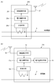
- FIG. 1 is a schematic configuration diagram of a charge management apparatus according to Embodiment 1 of the present invention.
- the charge management device in Embodiment 1 of the present invention is connected between the distribution line 3 and the indoor distribution board 4, and is a parent that measures the power consumption of each house such as a detached house or an apartment house. It includes a power meter 1 and a child power meter 2 provided in the middle of a charging wire 7 wired from a common power source 5 to an outlet 6 of an outdoor parking lot C of an electric vehicle or the like that is a charging position.
- the parent power meter 1 and the child power meter 2 are provided with wireless communication means (not shown) that performs wireless communication with each other by radio waves, light, sound waves, and the like. It transmits to the parent power meter 1 by radio.
- wireless communication means for example, Wi-Fi (registered trademark) standardized by Wi-Fi Alliance, Bluetooth (Bluetooth) specified in IEEE 802.15.1 ) (Registered trademark) or infrared communication can be used. It is also possible to use a mobile communication system such as a third generation mobile communication system (3G).
- the parent electric power meter 1 measures the electric energy used for each door by integrating the electric power used on the indoor distribution board 4 side. The measurement value transmitted by radio from the power meter 2 is received and integrated.
- the child power meter 2 measures the power or the amount of power used for charging the electric vehicle or the like C through the outlet 6, and transmits the measured value to the parent power meter 1 wirelessly.
- the sub power meter 2 measures the amount of power by measuring power or integrating power.
- the child power meter 2 When the child power meter 2 measures power, the child power meter 2 transmits the measured power data to the parent power meter 1 at any time, and integrates this power on the parent power meter 1 side. The amount is added to the power consumption of each door. On the other hand, when the child power meter 2 measures the amount of power, the measured power amount data is transmitted to the parent power meter 1 at a predetermined interval or at a predetermined timing such as after completion of charging. Add this amount of power to the amount of power used by each door.
- the common power source 5 can be a common power source for an apartment house, or a lead-in line from a distribution line such as a distribution line of a utility pole or an underground distribution line. It is of another system. It is desirable to use the common power source 5 as close as possible to the outlet 6 of the outdoor parking lot.
- the electric power or the electric energy used for the charging is measured by the sub power meter 2.
- the measured value is transmitted wirelessly to the parent power meter 1 that measures the amount of power used for each door.
- the parent power meter 1 measures the amount of power used for each door.
- the measured value is received by the parent power meter 1, it is integrated into the used electric energy for each door, so that it is possible to settle the fee as usual based on the used electric energy for each door measured by this parent electric power meter 1. it can.
- this charge management apparatus it is possible to manage each house with a simple configuration without centrally managing how many shared power sources 5 are used by the residents of each house for charging in an apartment house or a detached house. is there.
- no holes are made in the wall, and no external wall is formed, so that the aesthetic appearance is not impaired and the power loss is reduced.
- the parent power meter 1 and the child power meter 2 are configured to include wired communication means (not shown) that perform electrical communication with each other via a communication line such as an electric wire or an optical fiber. It is also possible.
- the wired communication means it is desirable to use, for example, power line communication (PLC; Power Line Communication). In this case, since the parent power meter 1 and the child power meter 2 can perform power line communication using the distribution line 3 and the charging wiring 7, it is not necessary to separately provide a communication line.
- the electric power or the electric energy used for the charging is the child electric power meter 2 as described above.
- the measured value is transmitted by wire to the parent power meter 1 that measures the amount of power used for each door. Then, when the measured value is received by the parent power meter 1, it is integrated into the used electric energy for each door, so that it is possible to settle the fee as usual based on the used electric energy for each door measured by this parent electric power meter 1. it can.
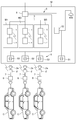
- FIG. 2 is a schematic configuration diagram of the charge management device according to Embodiment 2 of the present invention.
- the same components as those in FIG. 2 are identical components as those in FIG. 2;
- the housing complex M is provided with a power receiving / transforming facility 8 that transforms the power supply from the power company from a high voltage to a low voltage.
- the power receiving / transforming equipment 8 is connected to the parent power meter 1 installed in each of the dwelling units M1 to M3 by the distribution line 3 to each of the dwelling units M1 to M3, and supplies power to each of the dwelling units M1 to M3.
- the power receiving / transforming facility 8 is a shared power source 5 that measures the amount of power of the shared power source 5 to the respective outlets 51 for cleaning the indoor and outdoor lighting and the shared portion of the apartment house M as the shared power source 5. Power is supplied through 52.
- the power receiving / transforming facility 8 supplies power to the outlet 53 connected to a dedicated power line for charging the electric vehicle C or the like as the common power source 5.
- Three child electric power meters 2 are provided so that they can be used in three electric vehicles C owned by the residents of the dwelling units M1 to M3 of the apartment house M.
- the child power meter 2 is connected to a dedicated outlet 53 for charging the common power source 5 by a cable 2a with a plug.
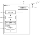
- the parent electric power meter 1 is an induction type watt hour meter that includes a rotating disk 11, a counter driving unit 12, a counter 13, an adding unit 14, and a wireless communication unit 15 for integrating and displaying the electric energy.
- the range of the dotted line surrounding the rotary disk 11, the counter drive means 12, and the counter 13 is the range of the inductive watt hour meter that is generally popular in the home.
- a voltage coil, a current coil, a control magnet, various compensation devices, and the like that rotate the rotating disk 11 are omitted.
- the rotating disk 11 rotates according to the use of electric power.
- the counter driving means 12 forms a screw gear on the rotating shaft of the rotating disk 11, and a helical gear meshes with the screw gear to form a worm gear.
- a gear group for transmitting the rotation is provided.
- the counter 13 is a mechanical counter formed so that the number “0” to “9” is written on the circumferential surface around the rotation axis, and the next digit is carried when the lower digit goes around. is there.
- the adding means 14 calculates the amount of electric power from the measured value notified from the sub power meter 2, and rotates the counter 13 in a state where the used power amount for each door is displayed according to the electric power amount. The amount of power measured by 2 is added.
- the wireless communication means 15 receives the wireless signal from the child power meter 2 via the antenna 16, decodes it, and outputs it to the adding means 14 as a measured value indicating the amount of power.
- the wireless communication unit 15 transmits an answerback indicating that the measurement value has been received to the child power meter 2 or transmits a retransmission request based on a reception error.
- the adding unit 14 includes a pulse generating unit 141, a solenoid 142, and a sensor 143.
- the pulse generating means 141 outputs a number of pulses corresponding to the measured value indicating the amount of power from the child power meter 2 to the solenoid 142 which is a count-up means.
- the solenoid 142 since the solenoid 142 is arranged to count up the second digit gear of the counter 13, one pulse is 1 kWh. Therefore, when the measured value indicating the electric power or the electric energy from the child power meter 2 is an integer value, a pulse is generated based on the value as it is, and when the value includes the decimal part, the decimal part is rounded off.
- a number of pulses based on only the integer value is generated. For example, if there is a notification of the power consumption of 10 kWh as a measurement value from the child power meter 2, the pulse generation means 141 generates 10 pulses. If the position corresponding to the first digit or less of the counter 13 of the measurement value notified from the child power meter 2 (in this case, the value after the decimal point) is added to the measurement value from the next child power meter 2, the fraction The amount of power can be calculated more accurately than processing.
- the solenoid 142 pushes the number gear 131 of the second digit of the counter 13 (1's digit of the electric energy) according to the number of pulses generated by the pulse generating means 141 and protrudes with the movement of the movable iron core (plunger). Is formed by a push-type solenoid that counts up when pressed.
- the sensor 143 notifies the pulse generation unit 141 of the carry of the number gear 132 in the first digit (the first decimal place of the electric energy) of the counter 13.
- a mark (not shown), which is identification information for detecting a carry, is given to the circumferential surface on which the numbers “0” to “9” of the first digit gear 132 of the counter 13 are written. ing. This is because when the counter driving means 12 drives the first digit gear 132 and the number of the first digit gear 132 changes from “9” to “0”, a carry occurs.
- the digit gear 131 is driven by the first digit gear 132 to detect the timing.
- the carry is the number of the first number gear 132. It occurs between “6” (see FIG. 5A) to “8” (see FIG. 5B). Marks that can be detected by the sensor 143 functioning as identification information are assigned to “6” to “8” of the first digit gear 132 of the counter 13.
- the pulse generation means 141 prohibits the output of the drive pulse to the solenoid 142 during the carry period in which the mark is detected. By doing so, it is possible to prevent the carry timing by the first digit gear 132 from overlapping with the addition timing to the second digit gear 131 by the solenoid 142. Therefore, the power amount of the child power meter 2 can be accurately added to the parent power meter 1.
- the carry position is detected by the mark by the sensor 143, but the number may be identified by a paint.
- paint that can be visually recognized and can be detected by the sensor 143 may be applied to “6” to “8” of the first digit gear 132.
- a fluorescent paint can be used as the paint.
- the sensor 143 is arranged right above the counter 13, but can be arranged at any place except the front. For example, when the sensor 143 is disposed on the back surface of the counter 13, the carry identification can be between “4” and ⁇ 6 ”.
- the count-up means includes a gear provided coaxially with the second digit of the counter 13 and the gear is provided with a counter 13 for each pulse. It is also possible to use a stepping motor that rotates one number.
- the parent power meter 1 can reliably add the amount of power notified from the child power meter 2 to the amount of power used for each door.
- the parent electric power meter 1 can be comprised by adding the structure of invention to the existing induction type watt-hour meter.
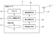
- the child power meter 2 is an inductive watt hour meter including a rotating disk 21, a counter driving unit 22, a counter 23, a rotation detecting unit 24, a power calculating unit 25, and a wireless communication unit 26.
- the rotating disk 21, the counter driving means 22 and the counter 23 can have the same configuration as the rotating disk 11, the counter driving means 12 and the counter 13 of the parent power meter 1.
- the rotation detection means 24 detects the rotation of the rotating disk 21.
- the rotation detecting means 24 receives an LED (Light Emitting Diode) that emits light toward the circumferential surface of the rotating disk 21 and the reflected light from the circumferential surface, and is reduced by a mark applied to the circumferential surface.
- a phototransistor that uses a current signal when light is emitted as a rotation detection signal can be obtained.
- the rotation detecting means 24 can be a rotary encoder that detects a hole provided in the rotating disk 21.
- the power calculation means 25 counts the detection of the rotation of the rotating disk 21 from the rotation detection means 24 and calculates the amount of power.
- the wireless communication unit 26 modulates communication data including a measurement value indicating the amount of power calculated by the power calculation unit 25 and transmits the communication data to the parent power meter 1 through the antenna 27 as a wireless signal. Further, the wireless communication means 26 receives a radio signal from the parent power meter 1 and demodulates it as received data. When the wireless communication means 26 communicates with the wireless communication means 15 of the parent power meter 1, various communication methods can be adopted.
- identification of parent power meter 1 as a communication destination “transmission of a measured value indicating the amount of power”, “reception confirmation of parent power meter 1”, and “confidentiality” are important.
- identification information (ID) for identifying the parent power meter 1 of the dwelling units M1 to M3 is set in advance, so that the transmission destination transmitted by the child power meter 2 can be determined.
- the measurement value is transmitted by being stored in the data portion (data frame) of the packet transmitted by the child power meter 2.
- check data for detecting a communication error on the receiving side is generated and added together with other data.
- the reception confirmation of the parent power meter 1 can be an answerback indicating that the parent power meter 1 has received communication from the child power meter 2.
- the slave power meter 2 assigns a serial number together with the measured value for each communication, and transmits it to the master power meter 1.
- the parent power meter 1 checks whether the serial number is missing, and if the serial number is missing, it can request retransmission by designating the missing serial number. Further, when the slave power meter 2 periodically transmits the measurement value, the transmission time can be used instead of the serial number. If the transmission time interval of the parent power meter 1 is longer than the interval of one time, it can be detected that the transmission of the child power meter 2 is lost. Further, when a communication error is detected in the parent power meter 2, an answer back indicating that a communication error has occurred is returned. In this way, the parent power meter 1 confirms reception, thereby improving communication reliability.
- AES Advanced Encryption Standard
- TKIP Temporal Key Integrity Protocol
- the child power meter 2 notifies the parent power meter 1 of the electric power or the amount of power charged in the electric vehicle C or the like safely and reliably. can do.
- FIG. 7 is a schematic configuration diagram of a parent power meter of the charge management device according to Embodiment 3 of the present invention.
- the parent power meter 10 shown in FIG. 7 can be used in place of the parent power meter 1 of the charge management apparatus in the second embodiment shown in FIG.
- the parent power meter 10 has the same configuration as the rotating disk 11, counter driving means 12, counter 13, wireless communication means 15, and antenna 16 of the parent power meter 1 shown in FIG. 3, and the child shown in FIG.
- the power meter 2 has the same configuration as the rotation detection means 24 of the power meter 2, a power calculation means 17, and a power amount display means 18.
- the range of the dotted line surrounding the rotating disk 11, the counter driving means 12, and the counter 13 is the range of the inductive watt hour meter that is generally popular in the home.
- the voltage coil and current coil for rotating the rotating disk 11, the control magnet, and various compensation devices are omitted.
- the power calculation means 17 integrates the power amount notified from the child power meter 2 to calculate the power amount used for charging the electric vehicle or the like C, and at the same time the rotation of the rotary disk 21 from the rotation detection means 24. The number of detections is counted, the amount of power used for each door is calculated, these amounts of power are added, and output to the power amount display means 18.
- the power calculation means 17 is preferably stored in a nonvolatile memory so that the added power amount can be maintained even during a power failure.
- the non-volatile memory can be a battery-backed memory or a flash memory.
- the electric energy display means 18 is an electric digital meter such as a liquid crystal panel, an EL (Electro Luminescence) panel, and a 7-segment LED.
- the parent power meter 10 calculates the power amount obtained by calculating the measurement value from the child power meter 2, and the power amount calculated by counting the rotation detected by the rotation detecting means 24, Even if the parent power meter 10 is formed by a mechanical inductive watt hour meter, the power calculation unit 17 adds and displays on the power amount display unit 18 formed by an electric digital meter.
- the electric power used by the electric vehicle or the like C for charging and the electric power used for each door can be integrated and displayed on the electric digital meter.
- the parent electric power meter 10 can be comprised by adding the structure of invention to the existing induction type watt-hour meter.
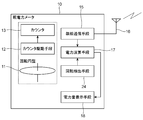
- FIGS. 8A and 8B are diagrams for explaining the charge management device according to the fourth embodiment of the present invention.
- FIG. 8A is a schematic configuration diagram of a child power meter
- FIG. 8B is a schematic configuration diagram of a parent power meter.
- the same components as those in FIGS. 3, 6, and 7 are given the same reference numerals and description thereof is omitted.
- a child power meter 20x shown in FIG. 8A can be used in place of the child power meter 2 of the charge management device in the third embodiment shown in FIG. 6, and the parent power meter 10x shown in FIG.
- the parent power meter 1 of the charge management apparatus in the second embodiment shown in FIG. 3 and the parent power meter 10 of the charge management apparatus in the third embodiment shown in FIG. 7 can be used.
- the child power meter 20x and the parent power meter 10x according to the fourth embodiment electrically measure power and display it electrically.
- a child power meter 20x shown in FIG. 8A includes a power measuring unit 28x, a power calculating unit 25x, and a wireless communication unit 26.
- the power measuring means 28x measures the current and voltage used for charging the shared power supply and notifies the power calculating means 25x.
- the power calculation means 25x calculates the power or the amount of power from the current and voltage measured by the power measurement means 28x, and transmits it to the parent power meter 10x via the wireless communication means 26.
- a child power meter 20x shown in FIG. 8A includes a measuring unit 28x, a power calculating unit 25x, and a wireless communication unit 26.
- the measuring means 28x measures the current and voltage used for charging the shared power supply 5 and notifies the power calculating means 25x.
- the power calculation means 25x calculates the power or the amount of power from the current and voltage measured by the measurement means 28x, and transmits it to the parent power meter 10x via the wireless communication means 26.
- a parent power meter 10x shown in FIG. 8B includes a measuring unit 19x, a power calculating unit 17x, a wireless communication unit 15, and a power amount display unit 18.
- the measuring unit 19x measures the current and voltage used in each dwelling unit of the distribution line 3 and notifies the power calculating unit 17x of the same as the measuring unit 25x.
- the power calculation unit 17x is configured to calculate the power or the power amount from the current and voltage measured by the measurement unit 28x, and the power from the slave power meter 20x received via the wireless communication unit 15 or The sum of the electric energy is added and displayed by the electric energy display means 18.
- the power calculation means 17x and the power calculation means 25x are preferably stored in a non-volatile memory so that the calculated amount of power can be maintained even during a power failure.
- the non-volatile memory can be a battery-backed memory or a flash memory.
- the measuring unit 28x measures the current and voltage at the shared power source 5
- the power calculating unit 25x calculates the amount of power from the current and voltage at the shared power source
- the wireless communication unit 26 By adopting a configuration in which the amount of electric power is transmitted to the parent electric power meter 10x, even if the child electric power meter 20x is an electric type, the electric amount used for charging by the electric vehicle or the like C can be notified to the parent electric meter 10x. .
- the measuring means 19x measures the current and voltage in the distribution line 3
- the power calculation means 17x calculates the amount of power calculated from the current and voltage in the distribution line 3
- the child power meter 20x By adding the electric energy and displaying the electric energy on the electric energy display means 18 formed by an electric digital meter, even if the parent electric power meter 10x is electric, the electric vehicle or the like C is charged. The amount of power used and the amount of power used for each door can be integrated and displayed on an electric digital meter.
- the charge management device is not limited to the mechanical type such as the inductive watt hour meter and the electronic type of the parent power meter 10x and the child power meter 20x. It is possible to manage each shared power supply 5 with a simple configuration without centralized management.
- the slave power meter wirelessly communicates the measured value to the parent power meter between the slave power meter and the master power meter by wireless communication means.
- wired communication may be performed by wired communication means. If there is a one-to-one wired communication between the child power meter and the parent power meter, there is no need to designate the parent power meter by an address. In this case, the child power meter has a predetermined integrated power. This may be notified by one pulse, and the parent power meter may count the pulse and integrate the amount of power used for charging. By doing so, it is possible to provide a simple interface for wired communication.
- the power meter 20x can be combined with each other by combining communication interfaces.
- the charge management device of the present invention is useful as a device for managing the amount of charge power of an electric vehicle, a plug-in hybrid vehicle, or the like.
Abstract
Provided is a charging management apparatus with which, when charging is carried out for an electric automobile or the like by using a shared power source not only in the case of a group residence but also in the case of an individual residence, management concerning to what extent the shared power source has been used for charging by the occupants of each residence is performed for each individual residence by means of a simple construction without centralized management. A charging management apparatus includes: a child power meter (2) which is provided midway on a charging lead (7) laid from a shared power source (5) to the charging location, measures the power or amount of power used in charging, and transmits the measured value wirelessly or by means of wires; and a parent power meter (1) which measures the amount of power used by each residence, receives the measured value transmitted from the child power meter (2), and integrates this with the amount of power used for each residence.
Description
本発明は、電気自動車やプラグインハイブリッド車などの充電電力量を管理する充電管理装置に関する。
The present invention relates to a charge management device that manages the amount of charge power of an electric vehicle, a plug-in hybrid vehicle, or the like.
電気自動車などの電動輸送機器(EV;Electric Vehicle)や、プラグインハイブリッド車などのプラグインハイブリッド式輸送機器(PHV;Plug-in Hybrid Vehicle)(以下、「電気自動車等」と称す。)を住居で充電する際には、通常、屋内分電盤より、専用線を分岐し、漏電防止付きブレーカーを介して電気自動車等の駐車場まで配線する必要がある。
Electric vehicles (EV) such as electric vehicles and plug-in hybrid vehicles (PHV) such as plug-in hybrid vehicles (hereinafter referred to as “electric vehicles”) are housed. When charging with, it is usually necessary to branch a dedicated line from the indoor distribution board and wire it to a parking lot such as an electric vehicle through a breaker with leakage prevention.
ここで、既存の住宅においては、壁に穴を開けたり、外壁に這わせたりして、電気自動車等の駐車場まで配線している。一戸建ての持ち家の住宅の場合には、美観上の問題以外に特に問題は生じにくいが、賃貸の一戸建て住宅、賃貸の集合住宅や、分譲の集合住宅の場合には、新築時にすでに設置している場合を除き、既存のものに充電施設を設けることには問題が多く、設置が不可能な場合も少なくない。また、集合住宅の共用電源を使用して充電する場合、各住人が充電にどれだけの共用電源を使用したかを把握する必要がある。
Here, in existing houses, holes are drilled in the walls or wired to the outer walls to route to parking lots such as electric cars. In the case of single-family homes, there are no particular problems other than aesthetic issues, but in the case of rental single-family homes, rental apartments, and condominiums that have already been installed, they have already been installed. Except for cases, there are many problems in installing charging facilities on existing ones, and there are many cases where installation is impossible. In addition, when charging using a shared power source of an apartment house, it is necessary to grasp how much shared power source each resident used for charging.
そこで、例えば特許文献1には、集合住宅の駐車場に駐車された車両を、共用電灯を使用して充電するための集合住宅用の車両充電システムが開示されている。この車両充電システムでは、集合住宅の駐車場の各駐車位置にそれぞれ充電ポストを設置し、各充電ポストと管理サーバとを通信線を介して通信可能に接続し、管理サーバによって各住人がそれぞれ車両の充電にどれだけの共用電灯を使用したかを集中管理する。
Therefore, for example, Patent Document 1 discloses a vehicle charging system for a collective housing for charging a vehicle parked in a parking lot of the collective housing using a common light. In this vehicle charging system, a charging post is installed at each parking position of a parking lot of an apartment house, and each charging post and a management server are communicably connected via a communication line. Centrally manage how many shared lamps are used for charging.
また、非特許文献1には、集合住宅に設置される宅配ボックスの機能を活用し、集合住宅の駐車場の各駐車位置にそれぞれ充電ユニット(子機)を設置し、各充電ユニットと認証装置(親機)とを接続し、認証装置を介して宅配ボックスと接続することにより、利用状況の把握および課金を行う電気自動車用充電システムが記載されている。
Further, Non-Patent Document 1 utilizes a function of a delivery box installed in an apartment house, and installs a charging unit (slave unit) at each parking position of an apartment house parking lot. A charging system for an electric vehicle is described in which a usage status is grasped and billed by connecting to a parent machine and connecting to a delivery box via an authentication device.
前述のように、集合住宅の共用電源を使用して充電する場合は、各住人が充電にどれだけの共用電源を使用したか把握する必要があるが、特許文献1や非特許文献1に記載のような充電システムを既存の共同住宅に導入する場合、集中管理する管理サーバや認証装置等の装置が必要となるため、多額の設置費用が発生することになり、その設置費用を誰が負担するのかが問題となる。また、分譲の集合住宅の場合には、住人全員の承諾が必要となり、電気自動車等を利用しない入居者の費用分担の問題も生じる。
As described above, when charging using a shared power source of an apartment house, it is necessary to grasp how many shared power sources each resident used for charging, but it is described in Patent Document 1 and Non-Patent Document 1. When a charging system such as the above is introduced into an existing apartment house, a centralized management server, authentication device, etc. are required, so a large installation cost will be incurred, and who will bear the installation cost Is a problem. Moreover, in the case of a condominium housing for sale, the consent of all residents is required, and there is a problem of cost sharing for residents who do not use electric vehicles.
そこで、本発明においては、集合住宅のみならず一戸建てにおいても共用電源を使用して電気自動車等の充電を行う場合に、各戸の住人が充電にどれだけの共用電源を使用したかを集中管理せずに簡単な構成で戸別に管理することが可能な充電管理装置を提供することを目的とする。
Therefore, in the present invention, when charging an electric vehicle or the like by using a common power source not only in an apartment house but also in a single-family house, centrally manage how many common power sources are used for charging by residents of each house. It is an object of the present invention to provide a charge management device that can be managed door to door with a simple configuration.
本発明の充電管理装置は、共用電源から充電位置まで配線された充電用電線の途中に設けられ、充電に使用された電力または電力量を計測し、計測値を無線または有線により送信する子電力メータと、戸別の使用電力量を計測する親電力メータであり、子電力メータから送信された計測値を受信し、戸別の使用電力量に積算する親電力メータとを含むものである。
The charge management device of the present invention is provided in the middle of a charging wire wired from a common power source to a charging position, measures the power or amount of power used for charging, and transmits the measured value wirelessly or by wire A meter and a parent power meter that measures the power consumption for each door, and includes a parent power meter that receives the measurement value transmitted from the child power meter and integrates the measured power amount for each door.
本発明の充電管理装置によれば、共用電源を利用して電気自動車等が充電されると、この充電に使用された電力または電力量が子電力メータにより計測され、その計測値が戸別の使用電力量を計測する親電力メータに無線または有線により送信される。そして、親電力メータにより計測値が受信されると、戸別の使用電力量に積算されるので、この親電力メータにより計測される戸別の使用電力量に基づいて従来通り料金精算することができる。
According to the charge management device of the present invention, when an electric vehicle or the like is charged using a common power source, the power or the amount of power used for the charging is measured by the child power meter, and the measured value is used for each door. It is transmitted wirelessly or by wire to a parent power meter that measures the amount of power. Then, when the measured value is received by the parent power meter, it is integrated into the used electric energy for each door, so that the fee can be settled as usual based on the used electric energy for each door measured by this parent electric power meter.
前記親電力メータは、機械式計数器により電力量を積算表示する誘導形電力量計により形成されており、前記子電力メータからの電力または電力量を示す計測値から演算された電力量に応じて、前記機械式計数機を回転させてカウントアップする加算手段とを備えるのが望ましい。
The parent power meter is formed by an inductive watt hour meter that integrates and displays a power amount with a mechanical counter, and depends on the power amount calculated from the power from the child power meter or the measured value indicating the power amount. And adding means for counting up by rotating the mechanical counter.
前記親電力メータが誘導形電力量計により形成されている場合、子電力メータからの計測値を演算することで得られた電力量に応じて、加算手段が機械式計数機を回転させてカウントアップすることで、子電力メータからの電力量を、親電力メータの電力量に加算することができる。従って、機械式計数機に、電気自動車等が充電に使用した電力量と戸別の使用電力量とを積算して表示させることができる。
When the parent power meter is formed of an inductive watt hour meter, the adding means rotates the mechanical counter and counts according to the amount of power obtained by calculating the measurement value from the child power meter. By increasing the power, the amount of power from the child power meter can be added to the amount of power of the parent power meter. Accordingly, the mechanical counter can integrate and display the amount of power used for charging by the electric vehicle or the like and the amount of power used for each door.
前記加算手段は、前記機械式計数器の1桁目の数字ギアに付与された桁上がりを示す識別情報を検出するセンサと、前記機械式計数器の1桁目の数字ギアの桁上がりが検出された期間以外に、前記子電力メータからの計測値に応じた数のパルスを発生するパルス発生手段と、前記パルス発生手段からのパルスに基づいて、前記機械式計数器の2桁目の数字ギアを回転させるカウントアップ手段とを備えるのが望ましい。
The adding means detects a detection information indicating a carry given to the first digit gear of the mechanical counter, and detects a carry of the first digit gear of the mechanical counter. A pulse generation means for generating a number of pulses corresponding to a measured value from the child power meter, and a second digit number of the mechanical counter based on the pulses from the pulse generation means. It is desirable to provide count-up means for rotating the gear.
機械式計数器では、その1桁目の数字ギアが回転駆動されることで計数される。また、2桁目の数字ギアは1桁目の数字ギアの桁上がりにより回転駆動される。したがって、カウントアップ手段による回転が、1桁目の数字ギアの桁上がりと重なると、正確にカウントアップできない。そこで、パルス発生手段は、センサにより検出した1桁目の数字ギアの桁上がり期間以外に、子電力メータからの計測値に応じた数のパルスを発生することで、1桁目の桁上がりと2桁目のカウントアップとの重なりを回避することができる。
In the mechanical counter, counting is performed by rotating the first digit gear. The second digit gear is driven to rotate by the carry of the first digit gear. Therefore, if the rotation by the count-up means overlaps with the carry of the first digit gear, it cannot be counted up accurately. Therefore, the pulse generating means generates the number of pulses corresponding to the measured value from the child power meter in addition to the carry period of the first digit gear detected by the sensor, thereby generating the first digit carry. Overlap with the second digit count-up can be avoided.
前記親電力メータは、電力に応じた渦電流を発生させて回転円盤を回転させ、電力量を積算表示する誘導形電力量計により形成されており、前記回転円盤の回転を検出する回転検出手段と、前記子電力メータからの電力または電力量を示す計測値から演算された電力量と、前記回転検出手段により検出された回転を計数して演算された電力量とを加算する電力演算手段と、前記電力演算手段により加算された電力量を表示する電気式デジタルメータにより形成された電力量表示手段とを備えるのが望ましい。
The parent power meter is formed of an inductive watt hour meter that generates an eddy current corresponding to the electric power to rotate the rotating disk and displays the electric energy in an integrated manner, and a rotation detecting unit that detects the rotation of the rotating disk. And an electric power calculating means for adding the electric energy calculated from the measured value indicating the electric power or the electric energy from the child electric power meter and the electric energy calculated by counting the rotation detected by the rotation detecting means; It is preferable that a power amount display means formed by an electric digital meter for displaying the power amount added by the power calculation means.
親電力メータを、子電力メータからの計測値を演算することで得られた電力量と、回転検出手段により検出された回転を計数して演算された電力量とを、電力演算手段が加算し、電気式デジタルメータにより形成された電力量表示手段に表示させる構成とすることで、親電力メータが機械式の誘導形電力量計により形成されていても、電気自動車等が充電に使用した電力量と戸別の使用電力量とを積算して電気式デジタルメータに表示させることができる。
The power calculation means adds the power amount obtained by calculating the measurement value from the child power meter to the parent power meter and the power amount calculated by counting the rotation detected by the rotation detection means. The electric power used by the electric vehicle etc. for charging even if the parent electric power meter is formed by a mechanical inductive watt hour meter by displaying on the electric energy display means formed by the electric digital meter. The amount and the amount of power used for each door can be integrated and displayed on the electric digital meter.
前記親電力メータは、前記配電線での電流および電圧を計測する計測手段と、前記計測手段による計測された電流および電圧から、電力または電力量を演算して得られた電力量と、前記子電力メータからの電力または電力量を積算して電力量とを加算する電力演算手段と、前記電力演算手段により加算された電力量を表示する電気式のデジタルメータにより形成された電力量表示手段とを備えるのが望ましい。
The parent power meter includes a measuring unit that measures a current and a voltage in the distribution line, a power amount obtained by calculating power or a power amount from the current and voltage measured by the measuring unit, and the child Power calculating means for adding up the electric power or the electric energy from the electric power meter and adding the electric energy; and an electric energy display means formed by an electric digital meter for displaying the electric energy added by the electric power calculating means; It is desirable to provide.
親電力メータを、計測手段が配電線での電流および電圧を計測し、電力演算手段が配電線での電流および電圧から演算した電力量と、子電力メータからの電力量とを加算して、電気式のデジタルメータにより形成された電力量表示手段に表示する構成とすることで、親電力メータが電気式であっても、電気自動車等が充電に使用した電力量と戸別の使用電力量とを積算して電気式のデジタルメータに表示させることができる。
For the parent power meter, the measuring means measures the current and voltage in the distribution line, the power calculation means adds the amount of power calculated from the current and voltage in the distribution line, and the amount of power from the child power meter, By displaying on the electric energy display means formed by an electric digital meter, even if the parent electric power meter is electric, the electric energy used for charging by the electric vehicle etc. and the electric energy used for each door Can be accumulated and displayed on an electric digital meter.
前記子電力メータは、電力に応じた渦電流を発生させて回転円盤を回転させ、電力量を積算表示する誘導形電力量計により形成されており、前記回転円盤の回転を検出する回転検出手段と、前記回転検出手段により検出された回転を計数して電力量を演算する電力演算手段と、前記電力演算手段により演算された電力量を前記親電力メータへ送信する通信手段とを備えるのが望ましい。
The child power meter is formed by an induction type watt hour meter that generates an eddy current according to electric power to rotate the rotating disk and displays the accumulated electric energy, and a rotation detecting means for detecting the rotation of the rotating disk Power calculating means for calculating the amount of power by counting the rotation detected by the rotation detecting means, and communication means for transmitting the amount of power calculated by the power calculating means to the parent power meter. desirable.
子電力メータを、回転検出手段により検出された回転を計数し、電力演算手段が回転数から電力量を演算し、通信手段により電力量を親電力メータへ送信する構成とすることで、子電力メータが機械式の誘導形電力量計により形成されていても、電気自動車等が充電に使用した電力量を親電気メータへ通知することができる。
By configuring the child power meter to count the rotation detected by the rotation detecting means, the power calculating means calculates the amount of power from the number of rotations, and the communication means transmits the amount of power to the parent power meter. Even if the meter is formed of a mechanical inductive watt hour meter, the amount of power used for charging by an electric vehicle or the like can be notified to the parent electric meter.
前記子電力メータは、前記共用電源での充填に使用される電流および電圧を計測する計測手段と、前記計測手段による計測された電流および電圧から、電力または電力量を演算する電力演算手段と、前記電力演算手段により演算された電力量を前記親電力メータへ送信する通信手段とを備えるのが望ましい。
The child power meter includes a measuring unit that measures a current and a voltage used for charging with the shared power source, a power calculating unit that calculates power or a power amount from the current and voltage measured by the measuring unit, It is desirable to provide communication means for transmitting the amount of power calculated by the power calculation means to the parent power meter.
子電力メータを、計測手段が共用電源での電流および電圧を計測し、電力演算手段が共用電源での電流および電圧から電力量を演算し、通信手段により電力量を親電力メータへ送信する構成とすることで、子電力メータが電気式であっても、電気自動車等が充電に使用した電力量を親電気メータへ通知することができる。
A configuration in which the measuring unit measures the current and voltage at the shared power source, the power calculating unit calculates the amount of power from the current and voltage at the shared power source, and the communication unit transmits the power amount to the parent power meter. Thus, even if the child power meter is an electric type, the amount of power used for charging by the electric vehicle or the like can be notified to the parent electric meter.
本発明によれば、共用電源を利用して電気自動車等を充電した場合に、親電力メータにより計測される戸別の使用電力量に基づいて従来通り料金精算することができるので、集合住宅のみならず一戸建てにおいても各戸の住人が充電にどれだけの共用電源を使用したかを集中管理せずに簡単な構成で戸別に管理することが可能となる。また、屋内分電盤から充電位置まで配線する必要がなく、壁に穴を開けたり、外壁に這わせたりすることがないため、美観を損ねることがなく、また電力ロスも少なくなる。
According to the present invention, when an electric vehicle or the like is charged using a common power source, the charge can be settled as usual based on the amount of power used for each door measured by the parent power meter. Even in a single-family house, it is possible to manage each resident with a simple configuration without centrally managing how many shared power sources each resident uses for charging. In addition, there is no need to wire from the indoor distribution board to the charging position, and there is no hole in the wall or no wall is placed on the outer wall, so that the aesthetic appearance is not impaired and the power loss is reduced.
1,10,10x 親電力メータ
11 回転円盤
12 カウンタ駆動手段
13 カウンタ
131 2桁目の数字ギア
132 1桁目の数字ギア
14 加算手段
141 パルス発生手段
142 ソレノイド
143 センサ
15 無線通信手段
16 アンテナ
17,17x 電力演算手段
18 電力量表示手段
19x 計測手段
2,20x 子電力メータ
2a プラグ付きのケーブル
21 回転円盤
22 カウンタ駆動手段
23 カウンタ
24 回転検出手段
25,25x 電力演算手段
26 無線通信手段
27 アンテナ
28x 計測手段
3 配電線
4 屋内分電盤
5 共用電源
51 コンセント
52 共用電源用電力メータ
53 コンセント
6 コンセント
7 充電用電線
8 受変電設備
M 集合住宅
M1~M3 住戸
C 電気自動車等 1, 10, 10xParent power meter 11 Rotating disk 12 Counter drive means 13 Counter 131 Second digit gear 132 First digit gear 14 Adder 141 Pulse generator 142 Solenoid 143 Sensor 15 Wireless communication means 16 Antenna 17 17x power calculation means 18 power amount display means 19x measurement means 2, 20x child power meter 2a cable with plug 21 rotating disk 22 counter drive means 23 counter 24 rotation detection means 25, 25x power calculation means 26 wireless communication means 27 antenna 28x measurement Means 3 Distribution line 4 Indoor distribution panel 5 Common power source 51 Outlet 52 Common power source power meter 53 Outlet 6 Outlet 7 Charging wire 8 Power receiving / transforming equipment M Apartment house M1-M3 Dwelling unit C Electric vehicle, etc.
11 回転円盤
12 カウンタ駆動手段
13 カウンタ
131 2桁目の数字ギア
132 1桁目の数字ギア
14 加算手段
141 パルス発生手段
142 ソレノイド
143 センサ
15 無線通信手段
16 アンテナ
17,17x 電力演算手段
18 電力量表示手段
19x 計測手段
2,20x 子電力メータ
2a プラグ付きのケーブル
21 回転円盤
22 カウンタ駆動手段
23 カウンタ
24 回転検出手段
25,25x 電力演算手段
26 無線通信手段
27 アンテナ
28x 計測手段
3 配電線
4 屋内分電盤
5 共用電源
51 コンセント
52 共用電源用電力メータ
53 コンセント
6 コンセント
7 充電用電線
8 受変電設備
M 集合住宅
M1~M3 住戸
C 電気自動車等 1, 10, 10x
(実施の形態1)
図1は本発明の実施の形態1における充電管理装置の概略構成図である。図1において、本発明の実施の形態1における充電管理装置は、配電線3と屋内分電盤4との間に接続され、一戸建てや集合住宅などの各戸の使用電力量を戸別に計測する親電力メータ1と、共用電源5から充電位置である電気自動車等Cの屋外駐車場のコンセント6まで配線された充電用電線7の途中に設けられた子電力メータ2とを含むものである。 (Embodiment 1)
FIG. 1 is a schematic configuration diagram of a charge management apparatus according toEmbodiment 1 of the present invention. In FIG. 1, the charge management device in Embodiment 1 of the present invention is connected between the distribution line 3 and the indoor distribution board 4, and is a parent that measures the power consumption of each house such as a detached house or an apartment house. It includes a power meter 1 and a child power meter 2 provided in the middle of a charging wire 7 wired from a common power source 5 to an outlet 6 of an outdoor parking lot C of an electric vehicle or the like that is a charging position.
図1は本発明の実施の形態1における充電管理装置の概略構成図である。図1において、本発明の実施の形態1における充電管理装置は、配電線3と屋内分電盤4との間に接続され、一戸建てや集合住宅などの各戸の使用電力量を戸別に計測する親電力メータ1と、共用電源5から充電位置である電気自動車等Cの屋外駐車場のコンセント6まで配線された充電用電線7の途中に設けられた子電力メータ2とを含むものである。 (Embodiment 1)
FIG. 1 is a schematic configuration diagram of a charge management apparatus according to
親電力メータ1と子電力メータ2とは、互いに電波、光や音波等により無線通信を行う無線通信手段(図示せず。)を備えており、後述するように子電力メータ2による計測値を親電力メータ1に無線により送信する。無線通信手段としては、例えば、ワイファイアライアンス(Wi-Fi Alliance)によって規格化されたワイファイ(Wi-Fi)(登録商標)、アイトリプルイー(IEEE)802.15.1に規定されたブルートゥース(Bluetooth)(登録商標)や赤外線通信などを用いることができる。また、第3世代移動通信システム(3G)などの移動通信システムを用いることも可能である。
The parent power meter 1 and the child power meter 2 are provided with wireless communication means (not shown) that performs wireless communication with each other by radio waves, light, sound waves, and the like. It transmits to the parent power meter 1 by radio. As the wireless communication means, for example, Wi-Fi (registered trademark) standardized by Wi-Fi Alliance, Bluetooth (Bluetooth) specified in IEEE 802.15.1 ) (Registered trademark) or infrared communication can be used. It is also possible to use a mobile communication system such as a third generation mobile communication system (3G).
親電力メータ1は、屋内分電盤4側で使用される電力を積算することにより戸別の使用電力量を計測するものであるが、本実施形態においてはさらにこの戸別の使用電力量に、子電力メータ2から無線により送信された計測値を受信して積算するものである。
The parent electric power meter 1 measures the electric energy used for each door by integrating the electric power used on the indoor distribution board 4 side. The measurement value transmitted by radio from the power meter 2 is received and integrated.
子電力メータ2は、コンセント6を通じて電気自動車等Cの充電に使用された電力または電力量を計測し、計測値を親電力メータ1に無線により送信するものである。子電力メータ2は、電力を計測するもの、あるいは電力を積算することにより電力量を計測するものである。
The child power meter 2 measures the power or the amount of power used for charging the electric vehicle or the like C through the outlet 6, and transmits the measured value to the parent power meter 1 wirelessly. The sub power meter 2 measures the amount of power by measuring power or integrating power.
子電力メータ2が電力を計測するものである場合、子電力メータ2は計測した電力のデータを随時、親電力メータ1に送信し、親電力メータ1側でこの電力を積算することにより、電力量として戸別の使用電力量に加算する。一方、子電力メータ2が電力量を計測するものである場合、計測した電力量のデータを、所定間隔あるいは充電完了後等の所定のタイミングで親電力メータ1に送信し、親電力メータ1側でこの電力量を戸別の使用電力量に加算する。
When the child power meter 2 measures power, the child power meter 2 transmits the measured power data to the parent power meter 1 at any time, and integrates this power on the parent power meter 1 side. The amount is added to the power consumption of each door. On the other hand, when the child power meter 2 measures the amount of power, the measured power amount data is transmitted to the parent power meter 1 at a predetermined interval or at a predetermined timing such as after completion of charging. Add this amount of power to the amount of power used by each door.
共用電源5は、集合住宅の共用電源や、電柱の配電線や地中の配電線等の配電線からの引き込み線を用いることができるが、親電力メータ1の屋内分電盤4側とは別系統のものである。共用電源5は、屋外駐車場のコンセント6にできるだけ近い位置のものを使用することが望ましい。
The common power source 5 can be a common power source for an apartment house, or a lead-in line from a distribution line such as a distribution line of a utility pole or an underground distribution line. It is of another system. It is desirable to use the common power source 5 as close as possible to the outlet 6 of the outdoor parking lot.
上記構成の充電管理装置では、屋外駐車場のコンセント6により共用電源5を利用して電気自動車等Cが充電されると、この充電に使用された電力または電力量が子電力メータ2により計測され、その計測値が戸別の使用電力量を計測する親電力メータ1に無線により送信される。そして、親電力メータ1により計測値が受信されると、戸別の使用電力量に積算されるので、この親電力メータ1により計測される戸別の使用電力量に基づいて従来通り料金精算することができる。
In the charge management device having the above configuration, when the electric vehicle or the like C is charged by using the common power source 5 by the outlet 6 of the outdoor parking lot, the electric power or the electric energy used for the charging is measured by the sub power meter 2. The measured value is transmitted wirelessly to the parent power meter 1 that measures the amount of power used for each door. Then, when the measured value is received by the parent power meter 1, it is integrated into the used electric energy for each door, so that it is possible to settle the fee as usual based on the used electric energy for each door measured by this parent electric power meter 1. it can.
したがって、この充電管理装置によれば、集合住宅や一戸建てにおいて、各戸の住人が充電にどれだけの共用電源5を使用したかを集中管理せずに簡単な構成で戸別に管理することが可能である。また、屋内分電盤4から充電位置まで配線する必要がなく、壁に穴を開けたり、外壁に這わせたりすることがないため、美観を損ねることがなく、また電力ロスも少なくなる。
Therefore, according to this charge management apparatus, it is possible to manage each house with a simple configuration without centrally managing how many shared power sources 5 are used by the residents of each house for charging in an apartment house or a detached house. is there. In addition, since there is no need to wire from the indoor distribution board 4 to the charging position, no holes are made in the wall, and no external wall is formed, so that the aesthetic appearance is not impaired and the power loss is reduced.
なお、上記無線通信手段に代えて、親電力メータ1と子電力メータ2とは、互いに電線や光ファイバーなどの通信線路による電気通信を行う有線通信手段(図示せず。)を備えた構成とすることも可能である。有線通信手段としては、例えば、電力線通信(PLC;Power Line Communication)を用いることが望ましい。この場合、親電力メータ1および子電力メータ2は、配電線3および充電用配線7を用いて電力線通信することができるため、通信線路を別途設ける必要がない。
Instead of the wireless communication means, the parent power meter 1 and the child power meter 2 are configured to include wired communication means (not shown) that perform electrical communication with each other via a communication line such as an electric wire or an optical fiber. It is also possible. As the wired communication means, it is desirable to use, for example, power line communication (PLC; Power Line Communication). In this case, since the parent power meter 1 and the child power meter 2 can perform power line communication using the distribution line 3 and the charging wiring 7, it is not necessary to separately provide a communication line.
このような構成においても、上述と同様、屋外駐車場のコンセント6により共用電源5を利用して電気自動車等Cが充電されると、この充電に使用された電力または電力量が子電力メータ2により計測され、その計測値が戸別の使用電力量を計測する親電力メータ1に有線により送信される。そして、親電力メータ1により計測値が受信されると、戸別の使用電力量に積算されるので、この親電力メータ1により計測される戸別の使用電力量に基づいて従来通り料金精算することができる。
Even in such a configuration, when the electric vehicle C or the like C is charged by using the common power source 5 by the outlet 6 of the outdoor parking lot, the electric power or the electric energy used for the charging is the child electric power meter 2 as described above. The measured value is transmitted by wire to the parent power meter 1 that measures the amount of power used for each door. Then, when the measured value is received by the parent power meter 1, it is integrated into the used electric energy for each door, so that it is possible to settle the fee as usual based on the used electric energy for each door measured by this parent electric power meter 1. it can.
(実施の形態2)
図2は、本発明の実施の形態2における充電管理装置の概略構成図である。なお、図2においては、図1と同じ構成のものは、同符号を付して説明を省略する。 (Embodiment 2)
FIG. 2 is a schematic configuration diagram of the charge management device according toEmbodiment 2 of the present invention. In FIG. 2, the same components as those in FIG.
図2は、本発明の実施の形態2における充電管理装置の概略構成図である。なお、図2においては、図1と同じ構成のものは、同符号を付して説明を省略する。 (Embodiment 2)
FIG. 2 is a schematic configuration diagram of the charge management device according to
図2において、集合住宅Mには、電力会社からの給電を高圧から低圧に変圧する受変電設備8が設置されている。受変電設備8は、各住戸M1~M3に設置された親電力メータ1に、各住戸M1~M3への配電線3により接続され、各住戸M1~M3へ電力を供給している。また、受変電設備8は、共用電源5として、集合住宅Mの屋内外の照明および共用部分の清掃をするためのそれぞれのコンセント51へ、共用電源5の電力量を計測する共用電源用電力メータ52を介して給電している。また、受変電設備8は、共用電源5として、電気自動車等Cを充電するための専用電源線に接続されたコンセント53へ給電している。
Referring to FIG. 2, the housing complex M is provided with a power receiving / transforming facility 8 that transforms the power supply from the power company from a high voltage to a low voltage. The power receiving / transforming equipment 8 is connected to the parent power meter 1 installed in each of the dwelling units M1 to M3 by the distribution line 3 to each of the dwelling units M1 to M3, and supplies power to each of the dwelling units M1 to M3. In addition, the power receiving / transforming facility 8 is a shared power source 5 that measures the amount of power of the shared power source 5 to the respective outlets 51 for cleaning the indoor and outdoor lighting and the shared portion of the apartment house M as the shared power source 5. Power is supplied through 52. In addition, the power receiving / transforming facility 8 supplies power to the outlet 53 connected to a dedicated power line for charging the electric vehicle C or the like as the common power source 5.
子電力メータ2は、集合住宅Mの住戸M1~M3の住人が所有する3台分の電気自動車等Cで利用できるように、3台設けられている。この子電力メータ2は、プラグ付きのケーブル2aにより共用電源5の充電専用のコンセント53に接続されている。
Three child electric power meters 2 are provided so that they can be used in three electric vehicles C owned by the residents of the dwelling units M1 to M3 of the apartment house M. The child power meter 2 is connected to a dedicated outlet 53 for charging the common power source 5 by a cable 2a with a plug.
ここで、親電力メータ1について、図3に基づいて詳細に説明する。
親電力メータ1は、回転円盤11と、カウンタ駆動手段12と、カウンタ13と、加算手段14と、無線通信手段15とを備えた、電力量を積算表示する誘導形電力量計である。図3においては、回転円盤11と、カウンタ駆動手段12と、カウンタ13とを囲む点線の範囲が、一般的に家庭に普及している誘導形電力量計の範囲である。なお、図3では、回転円盤11を回転させる電圧コイルや電流コイル、制御用磁石および各種の補償装置などは省略している。
回転円盤11は、電力の使用に応じて回転する。カウンタ駆動手段12は、回転円盤11の回転をカウンタ13へ伝達するために、回転円盤11の回転軸にねじ歯車を形成し、このねじ歯車にはす歯歯車を噛み合せてウォームギアとし、このウォームギアからの回転を伝達するギア群を設けた構成としたものである。 Here, theparent power meter 1 will be described in detail with reference to FIG.
The parentelectric power meter 1 is an induction type watt hour meter that includes a rotating disk 11, a counter driving unit 12, a counter 13, an adding unit 14, and a wireless communication unit 15 for integrating and displaying the electric energy. In FIG. 3, the range of the dotted line surrounding the rotary disk 11, the counter drive means 12, and the counter 13 is the range of the inductive watt hour meter that is generally popular in the home. In FIG. 3, a voltage coil, a current coil, a control magnet, various compensation devices, and the like that rotate the rotating disk 11 are omitted.
Therotating disk 11 rotates according to the use of electric power. In order to transmit the rotation of the rotating disk 11 to the counter 13, the counter driving means 12 forms a screw gear on the rotating shaft of the rotating disk 11, and a helical gear meshes with the screw gear to form a worm gear. In this configuration, a gear group for transmitting the rotation is provided.
親電力メータ1は、回転円盤11と、カウンタ駆動手段12と、カウンタ13と、加算手段14と、無線通信手段15とを備えた、電力量を積算表示する誘導形電力量計である。図3においては、回転円盤11と、カウンタ駆動手段12と、カウンタ13とを囲む点線の範囲が、一般的に家庭に普及している誘導形電力量計の範囲である。なお、図3では、回転円盤11を回転させる電圧コイルや電流コイル、制御用磁石および各種の補償装置などは省略している。
回転円盤11は、電力の使用に応じて回転する。カウンタ駆動手段12は、回転円盤11の回転をカウンタ13へ伝達するために、回転円盤11の回転軸にねじ歯車を形成し、このねじ歯車にはす歯歯車を噛み合せてウォームギアとし、このウォームギアからの回転を伝達するギア群を設けた構成としたものである。 Here, the
The parent
The
カウンタ13は、回転軸を中心に、円周面に「0」~「9」の数字が表記され、下桁が一周すれば次の桁が桁上がりするように形成された機械式計数器である。
加算手段14は、子電力メータ2から通知された計測値から電力量を演算し、この電力量に応じて戸別の使用電力量を表示している状態のカウンタ13を回転させて、子電力メータ2により計測された電力量を加算するものである。
無線通信手段15は、子電力メータ2からの無線信号を、アンテナ16を介して受信して、復号して電力量を示す計測値として加算手段14へ出力する。また、無線通信手段15は、子電力メータ2へ計測値を受信したことを示すアンサーバックを送信したり、受信エラーに基づく再送要求を送信したりする。 Thecounter 13 is a mechanical counter formed so that the number “0” to “9” is written on the circumferential surface around the rotation axis, and the next digit is carried when the lower digit goes around. is there.
The adding means 14 calculates the amount of electric power from the measured value notified from thesub power meter 2, and rotates the counter 13 in a state where the used power amount for each door is displayed according to the electric power amount. The amount of power measured by 2 is added.
The wireless communication means 15 receives the wireless signal from thechild power meter 2 via the antenna 16, decodes it, and outputs it to the adding means 14 as a measured value indicating the amount of power. The wireless communication unit 15 transmits an answerback indicating that the measurement value has been received to the child power meter 2 or transmits a retransmission request based on a reception error.
加算手段14は、子電力メータ2から通知された計測値から電力量を演算し、この電力量に応じて戸別の使用電力量を表示している状態のカウンタ13を回転させて、子電力メータ2により計測された電力量を加算するものである。
無線通信手段15は、子電力メータ2からの無線信号を、アンテナ16を介して受信して、復号して電力量を示す計測値として加算手段14へ出力する。また、無線通信手段15は、子電力メータ2へ計測値を受信したことを示すアンサーバックを送信したり、受信エラーに基づく再送要求を送信したりする。 The
The adding means 14 calculates the amount of electric power from the measured value notified from the
The wireless communication means 15 receives the wireless signal from the
ここで、カウンタ13および加算手段14よる電力量の加算について、図4および図5に基づいて詳細に説明する。
図4に示すように、加算手段14は、パルス発生手段141と、ソレノイド142と、センサ143とを備えている。 Here, the addition of the electric energy by thecounter 13 and the adding means 14 will be described in detail based on FIG. 4 and FIG.
As shown in FIG. 4, the addingunit 14 includes a pulse generating unit 141, a solenoid 142, and a sensor 143.
図4に示すように、加算手段14は、パルス発生手段141と、ソレノイド142と、センサ143とを備えている。 Here, the addition of the electric energy by the
As shown in FIG. 4, the adding
パルス発生手段141は、子電力メータ2からの電力量を示す計測値に応じた数のパルスを、カウントアップ手段であるソレノイド142へ出力する。本実施の形態では、詳細には後述するが、ソレノイド142がカウンタ13の2桁目の数字ギアをカウントアップするように配置されているので、1つのパルスは1kWhとなる。したがって、子電力メータ2からの電力または電力量を示す計測値が整数値であるときには、そのままの値に基づいてパルスを発生し、小数点以下を含む値であるときは小数点以下を、四捨五入した値、切り上げた値または切り捨てた値、或いは、小数点以下を次回の電力量の測定値に加算するために整数値のみの値に基づいた数のパルスを発生する。
例えば、パルス発生手段141は、子電力メータ2から計測値として、10kWhの消費電力量の通知があれば、10回のパルス発生を行う。
子電力メータ2から通知された測定値のカウンタ13の一桁目以下に対応する位(この場合、小数点以下の値。)を、次回の子電力メータ2からの測定値に加算すれば、端数処理するより正確に電力量を演算することができる。 The pulse generating means 141 outputs a number of pulses corresponding to the measured value indicating the amount of power from thechild power meter 2 to the solenoid 142 which is a count-up means. In the present embodiment, as will be described in detail later, since the solenoid 142 is arranged to count up the second digit gear of the counter 13, one pulse is 1 kWh. Therefore, when the measured value indicating the electric power or the electric energy from the child power meter 2 is an integer value, a pulse is generated based on the value as it is, and when the value includes the decimal part, the decimal part is rounded off. In order to add the rounded-up or rounded-down value, or the value after the decimal point to the measured value of the next electric energy, a number of pulses based on only the integer value is generated.
For example, if there is a notification of the power consumption of 10 kWh as a measurement value from thechild power meter 2, the pulse generation means 141 generates 10 pulses.
If the position corresponding to the first digit or less of thecounter 13 of the measurement value notified from the child power meter 2 (in this case, the value after the decimal point) is added to the measurement value from the next child power meter 2, the fraction The amount of power can be calculated more accurately than processing.
例えば、パルス発生手段141は、子電力メータ2から計測値として、10kWhの消費電力量の通知があれば、10回のパルス発生を行う。
子電力メータ2から通知された測定値のカウンタ13の一桁目以下に対応する位(この場合、小数点以下の値。)を、次回の子電力メータ2からの測定値に加算すれば、端数処理するより正確に電力量を演算することができる。 The pulse generating means 141 outputs a number of pulses corresponding to the measured value indicating the amount of power from the
For example, if there is a notification of the power consumption of 10 kWh as a measurement value from the
If the position corresponding to the first digit or less of the
ソレノイド142は、パルス発生手段141が発生したパルス数に応じて、カウンタ13の2桁目(電力量の1の位)の数字ギア131を、可動鉄心(プランジャー)の移動と共に突出するプッシュバーが押圧してカウントアップするプッシュ型ソレノイドにより形成されている。
センサ143は、カウンタ13の1桁目(電力量の小数点第1位)の数字ギア132の桁上がりをパルス発生手段141へ通知する。 Thesolenoid 142 pushes the number gear 131 of the second digit of the counter 13 (1's digit of the electric energy) according to the number of pulses generated by the pulse generating means 141 and protrudes with the movement of the movable iron core (plunger). Is formed by a push-type solenoid that counts up when pressed.
Thesensor 143 notifies the pulse generation unit 141 of the carry of the number gear 132 in the first digit (the first decimal place of the electric energy) of the counter 13.
センサ143は、カウンタ13の1桁目(電力量の小数点第1位)の数字ギア132の桁上がりをパルス発生手段141へ通知する。 The
The
カウンタ13の1桁目の数字ギア132の「0」~「9」の数字が表記された円周面には、桁上がりを検知するための識別情報であるマーク(図示せず)が付与されている。これは、カウンタ駆動手段12が1桁目の数字ギア132を駆動しており、1桁目の数字ギア132の数字が「9」から「0」となるときに桁上がりが発生して、2桁目の数字ギア131が1桁目の数字ギア132により駆動されるので、そのタイミングを検出するためのである。
A mark (not shown), which is identification information for detecting a carry, is given to the circumferential surface on which the numbers “0” to “9” of the first digit gear 132 of the counter 13 are written. ing. This is because when the counter driving means 12 drives the first digit gear 132 and the number of the first digit gear 132 changes from “9” to “0”, a carry occurs. The digit gear 131 is driven by the first digit gear 132 to detect the timing.
カウンタ13は正面から目視されるので、センサ143が数字ギアの真上の位置から円周面の状態を読み取るように配置されていれば、桁上がりは、1桁目の数字ギア132の数字が「6」(図5(A)参照)~「8」(図5(B)参照)の間に発生する。カウンタ13の1桁目の数字ギア132の「6」~「8」には、識別情報として機能するセンサ143により検出可能なマークが付与されている。
Since the counter 13 is visually observed from the front, if the sensor 143 is arranged so as to read the state of the circumferential surface from a position directly above the number gear, the carry is the number of the first number gear 132. It occurs between “6” (see FIG. 5A) to “8” (see FIG. 5B). Marks that can be detected by the sensor 143 functioning as identification information are assigned to “6” to “8” of the first digit gear 132 of the counter 13.
センサ143によりこのマークを検出し、パルス発生手段141へ通知することで、パルス発生手段141は、マークが検出されている桁上がりの期間中、ソレノイド142への駆動パルスの出力を禁止する。そうすることで、1桁目の数字ギア132による桁上がりのタイミングと、ソレノイド142による2桁目の数字ギア131への加算のタイミングとが重なることを回避することができる。したがって、正確に子電力メータ2の電力量を親電力メータ1へ加算することができる。
By detecting this mark by the sensor 143 and notifying the pulse generation means 141, the pulse generation means 141 prohibits the output of the drive pulse to the solenoid 142 during the carry period in which the mark is detected. By doing so, it is possible to prevent the carry timing by the first digit gear 132 from overlapping with the addition timing to the second digit gear 131 by the solenoid 142. Therefore, the power amount of the child power meter 2 can be accurately added to the parent power meter 1.
なお、本実施の形態2では、センサ143により桁上がり位置の検出はマークにより行なっているが、塗料により数字を識別するようにしてもよい。例えば、1桁目の数字ギア132の「6」~「8」に数字が視認でき、かつセンサ143で検出できる塗料を塗布するようにしてもよい。塗料としては蛍光塗料が使用できる。
また、本実施の形態2では、センサ143をカウンタ13の真上に配置しているが、正面を除く任意の場所に配置することもできる。例えば、センサ143をカウンタ13の背面に配置したときには、桁上がりの識別を「4」~{6」の間とすることができる。 In the second embodiment, the carry position is detected by the mark by thesensor 143, but the number may be identified by a paint. For example, paint that can be visually recognized and can be detected by the sensor 143 may be applied to “6” to “8” of the first digit gear 132. A fluorescent paint can be used as the paint.
In the second embodiment, thesensor 143 is arranged right above the counter 13, but can be arranged at any place except the front. For example, when the sensor 143 is disposed on the back surface of the counter 13, the carry identification can be between “4” and {6 ”.
また、本実施の形態2では、センサ143をカウンタ13の真上に配置しているが、正面を除く任意の場所に配置することもできる。例えば、センサ143をカウンタ13の背面に配置したときには、桁上がりの識別を「4」~{6」の間とすることができる。 In the second embodiment, the carry position is detected by the mark by the
In the second embodiment, the
また、本実施の形態2では、カウントアップ手段としてソレノイドを使用しているが、カウントアップ手段は、カウンタ13の2桁目と同軸に設けられたギアと、このギアを1パルスごとにカウンタ13の数字1つ分を回転させるステッピングモータとすることもできる。
In the second embodiment, a solenoid is used as the count-up means. However, the count-up means includes a gear provided coaxially with the second digit of the counter 13 and the gear is provided with a counter 13 for each pulse. It is also possible to use a stepping motor that rotates one number.
このように親電力メータ1は、子電力メータ2から通知された電力量を、戸別の使用電力量に確実に加算することができる。また、既存の誘導形電力量計に発明の構成を加えることで、親電力メータ1を構成することができる。
Thus, the parent power meter 1 can reliably add the amount of power notified from the child power meter 2 to the amount of power used for each door. Moreover, the parent electric power meter 1 can be comprised by adding the structure of invention to the existing induction type watt-hour meter.
次に、子電力メータ2について、図6に基づいて詳細に説明する。なお、図6においては、図3と同様に、回転円盤21を回転させる電圧コイル、電流コイル、制御用磁石および各種の補償装置などは省略している。
子電力メータ2は、回転円盤21と、カウンタ駆動手段22と、カウンタ23と、回転検出手段24と、電力演算手段25と、無線通信手段26とを備えた誘導形電力量計である。
回転円盤21とカウンタ駆動手段22とカウンタ23は、親電力メータ1の回転円盤11とカウンタ駆動手段12とカウンタ13と、同様の構成とすることができる。 Next, thechild power meter 2 will be described in detail with reference to FIG. In FIG. 6, as in FIG. 3, the voltage coil, current coil, control magnet, various compensation devices, and the like that rotate the rotating disk 21 are omitted.
Thechild power meter 2 is an inductive watt hour meter including a rotating disk 21, a counter driving unit 22, a counter 23, a rotation detecting unit 24, a power calculating unit 25, and a wireless communication unit 26.
Therotating disk 21, the counter driving means 22 and the counter 23 can have the same configuration as the rotating disk 11, the counter driving means 12 and the counter 13 of the parent power meter 1.
子電力メータ2は、回転円盤21と、カウンタ駆動手段22と、カウンタ23と、回転検出手段24と、電力演算手段25と、無線通信手段26とを備えた誘導形電力量計である。
回転円盤21とカウンタ駆動手段22とカウンタ23は、親電力メータ1の回転円盤11とカウンタ駆動手段12とカウンタ13と、同様の構成とすることができる。 Next, the
The
The
回転検出手段24は、回転円盤21の回転を検出するものである。例えば、回転検出手段24は、回転円盤21の円周面に向けて発光するLED(Light Emitting Diode)と、円周面からの反射光を受光して、円周面に付与されたマークにより減光したときの電流信号を回転検出信号とするフォトトランジスタとすることができる。また、回転検出手段24は、回転円盤21に設けられた孔を検出するロータリーエンコーダとすることができる。
電力演算手段25は、回転検出手段24からの回転円盤21の回転の検出を計数して、電力量を演算する。 The rotation detection means 24 detects the rotation of therotating disk 21. For example, the rotation detecting means 24 receives an LED (Light Emitting Diode) that emits light toward the circumferential surface of the rotating disk 21 and the reflected light from the circumferential surface, and is reduced by a mark applied to the circumferential surface. A phototransistor that uses a current signal when light is emitted as a rotation detection signal can be obtained. Further, the rotation detecting means 24 can be a rotary encoder that detects a hole provided in the rotating disk 21.
The power calculation means 25 counts the detection of the rotation of therotating disk 21 from the rotation detection means 24 and calculates the amount of power.
電力演算手段25は、回転検出手段24からの回転円盤21の回転の検出を計数して、電力量を演算する。 The rotation detection means 24 detects the rotation of the
The power calculation means 25 counts the detection of the rotation of the
無線通信手段26は、電力演算手段25により演算された電力量を示す計測値を含む通信データを変調して無線信号として、アンテナ27を介して親電力メータ1へ送信する。また、無線通信手段26は、親電力メータ1からの無線信号を受信して受信データとして復調する。無線通信手段26が親電力メータ1の無線通信手段15と通信するときには、様々な通信方式が採用できる。
The wireless communication unit 26 modulates communication data including a measurement value indicating the amount of power calculated by the power calculation unit 25 and transmits the communication data to the parent power meter 1 through the antenna 27 as a wireless signal. Further, the wireless communication means 26 receives a radio signal from the parent power meter 1 and demodulates it as received data. When the wireless communication means 26 communicates with the wireless communication means 15 of the parent power meter 1, various communication methods can be adopted.
これらの通信方式では、「通信先となる親電力メータ1の特定」、「電力量を示す計測値の送信」、「親電力メータ1の受信確認」および「秘匿性」が重要となる。
親電力メータ1の特定については、住戸M1~M3の親電力メータ1を識別する識別情報(ID)が予め設定されることにより、子電力メータ2が送信する送信先を決定することができる。計測値の送信は、子電力メータ2が送信するパケットのデータ部(データフレーム)に格納されて行われる。また、子電力メータ2が計測値を送信するときに、他のデータと共に、受信側で通信エラーを検出するためのチェックデータが生成されて付加される。 In these communication methods, “identification ofparent power meter 1 as a communication destination”, “transmission of a measured value indicating the amount of power”, “reception confirmation of parent power meter 1”, and “confidentiality” are important.
For specifying theparent power meter 1, identification information (ID) for identifying the parent power meter 1 of the dwelling units M1 to M3 is set in advance, so that the transmission destination transmitted by the child power meter 2 can be determined. The measurement value is transmitted by being stored in the data portion (data frame) of the packet transmitted by the child power meter 2. When the child power meter 2 transmits the measurement value, check data for detecting a communication error on the receiving side is generated and added together with other data.
親電力メータ1の特定については、住戸M1~M3の親電力メータ1を識別する識別情報(ID)が予め設定されることにより、子電力メータ2が送信する送信先を決定することができる。計測値の送信は、子電力メータ2が送信するパケットのデータ部(データフレーム)に格納されて行われる。また、子電力メータ2が計測値を送信するときに、他のデータと共に、受信側で通信エラーを検出するためのチェックデータが生成されて付加される。 In these communication methods, “identification of
For specifying the
親電力メータ1の受信確認は、子電力メータ2からの通信を親電力メータ1が受信したことを示すアンサーバックとすることができる。例えば、子電力メータ2が通信ごとに、計測値と共にシリアル番号を付与して、親電力メータ1へ送信する。そうすることで、親電力メータ1では、シリアル番号に抜けが無いかをチェックして、シリアル番号が抜けていれば、抜けたシリアル番号を指定して再送を要求することができる。また、子電力メータ2が計測値を定期的に送信する場合、送信時刻をシリアル番号の代わりとすることができる。親電力メータ1は送信時刻の間隔が1回分の間隔より長くなっていれば、子電力メータ2の送信に抜けが発生したことが検出できる。更に、親電力メータ2にて通信エラーを検出した場合、通信エラーが発生した旨のアンサーバックを返信する。
このようにして、親電力メータ1が受信確認することで、通信の信頼性を向上させることができる。 The reception confirmation of theparent power meter 1 can be an answerback indicating that the parent power meter 1 has received communication from the child power meter 2. For example, the slave power meter 2 assigns a serial number together with the measured value for each communication, and transmits it to the master power meter 1. By doing so, the parent power meter 1 checks whether the serial number is missing, and if the serial number is missing, it can request retransmission by designating the missing serial number. Further, when the slave power meter 2 periodically transmits the measurement value, the transmission time can be used instead of the serial number. If the transmission time interval of the parent power meter 1 is longer than the interval of one time, it can be detected that the transmission of the child power meter 2 is lost. Further, when a communication error is detected in the parent power meter 2, an answer back indicating that a communication error has occurred is returned.
In this way, theparent power meter 1 confirms reception, thereby improving communication reliability.
このようにして、親電力メータ1が受信確認することで、通信の信頼性を向上させることができる。 The reception confirmation of the
In this way, the
秘匿性については、通信パケットを暗号化することで、安全を確保することができる。例えば、AES(Advanced Encryption Standard)やTKIP(Temporal Key Integrity Protocol)などとすることができる。
As for confidentiality, security can be ensured by encrypting communication packets. For example, AES (Advanced Encryption Standard) or TKIP (Temporal Key Integrity Protocol) can be used.
このように親電力メータ1と子電力メータ2とが離れていても、子電力メータ2は、安全で、かつ確実に親電力メータ1へ、電気自動車等Cに充電した電力または電力量を通知することができる。
Thus, even if the parent power meter 1 and the child power meter 2 are separated from each other, the child power meter 2 notifies the parent power meter 1 of the electric power or the amount of power charged in the electric vehicle C or the like safely and reliably. can do.
(実施の形態3)
図7は本発明の実施の形態3における充電管理装置の親電力メータの概略構成図である。図7に示す親電力メータ10は、図2に示す実施の形態2における充電管理装置の親電力メータ1の代わりとすることができる。 (Embodiment 3)
FIG. 7 is a schematic configuration diagram of a parent power meter of the charge management device according toEmbodiment 3 of the present invention. The parent power meter 10 shown in FIG. 7 can be used in place of the parent power meter 1 of the charge management apparatus in the second embodiment shown in FIG.
図7は本発明の実施の形態3における充電管理装置の親電力メータの概略構成図である。図7に示す親電力メータ10は、図2に示す実施の形態2における充電管理装置の親電力メータ1の代わりとすることができる。 (Embodiment 3)
FIG. 7 is a schematic configuration diagram of a parent power meter of the charge management device according to
親電力メータ10は、図3に示される親電力メータ1の回転円盤11、カウンタ駆動手段12、カウンタ13、無線通信手段15、アンテナ16と同じ構成のものと、図6に示めされる子電力メータ2の回転検出手段24と同じ構成のものと、電力演算手段17と、電力量表示手段18とを備えている。図7においては、図3と同様に、回転円盤11と、カウンタ駆動手段12と、カウンタ13とを囲む点線の範囲が、一般的に家庭に普及している誘導形電力量計の範囲である。なお、図7においても、回転円盤11を回転させる電圧コイルや電流コイル、制御用磁石および各種の補償装置などは省略している。
The parent power meter 10 has the same configuration as the rotating disk 11, counter driving means 12, counter 13, wireless communication means 15, and antenna 16 of the parent power meter 1 shown in FIG. 3, and the child shown in FIG. The power meter 2 has the same configuration as the rotation detection means 24 of the power meter 2, a power calculation means 17, and a power amount display means 18. In FIG. 7, as in FIG. 3, the range of the dotted line surrounding the rotating disk 11, the counter driving means 12, and the counter 13 is the range of the inductive watt hour meter that is generally popular in the home. . Also in FIG. 7, the voltage coil and current coil for rotating the rotating disk 11, the control magnet, and various compensation devices are omitted.
電力演算手段17は、子電力メータ2から通知された電力量を積算して、電気自動車等Cの充電に使用された電力量を算出すると共に、回転検出手段24からの回転円盤21の回転の検出を計数して、戸別の使用電力量を算出して、これらの電力量を加算し、電力量表示手段18へ出力するものである。電力演算手段17は、加算した電力量を停電時にも維持できるよう不揮発性メモリに保存しておくのが望ましい。不揮発性メモリはバッテリバックアップされたメモリやフラッシュメモリとすることができる。
電力量表示手段18は、液晶パネル、EL(Electro Luminescence)パネル、7セグメントのLEDなどの電気式のデジタルメータである。 The power calculation means 17 integrates the power amount notified from thechild power meter 2 to calculate the power amount used for charging the electric vehicle or the like C, and at the same time the rotation of the rotary disk 21 from the rotation detection means 24. The number of detections is counted, the amount of power used for each door is calculated, these amounts of power are added, and output to the power amount display means 18. The power calculation means 17 is preferably stored in a nonvolatile memory so that the added power amount can be maintained even during a power failure. The non-volatile memory can be a battery-backed memory or a flash memory.
The electric energy display means 18 is an electric digital meter such as a liquid crystal panel, an EL (Electro Luminescence) panel, and a 7-segment LED.
電力量表示手段18は、液晶パネル、EL(Electro Luminescence)パネル、7セグメントのLEDなどの電気式のデジタルメータである。 The power calculation means 17 integrates the power amount notified from the
The electric energy display means 18 is an electric digital meter such as a liquid crystal panel, an EL (Electro Luminescence) panel, and a 7-segment LED.
このように親電力メータ10を、子電力メータ2からの計測値を演算することで得られた電力量と、回転検出手段24により検出された回転を計数して演算された電力量とを、電力演算手段17が加算し、電気式デジタルメータにより形成された電力量表示手段18に表示させる構成とすることで、親電力メータ10が機械式の誘導形電力量計により形成されていても、電気自動車等Cが充電に使用した電力量と戸別の使用電力量とを積算して電気式デジタルメータに表示させることができる。
Thus, the parent power meter 10 calculates the power amount obtained by calculating the measurement value from the child power meter 2, and the power amount calculated by counting the rotation detected by the rotation detecting means 24, Even if the parent power meter 10 is formed by a mechanical inductive watt hour meter, the power calculation unit 17 adds and displays on the power amount display unit 18 formed by an electric digital meter. The electric power used by the electric vehicle or the like C for charging and the electric power used for each door can be integrated and displayed on the electric digital meter.
従って、各戸の住人が充電にどれだけの共用電源5を使用したかを集中管理せずに簡単な構成で戸別に管理することが可能である。また、既存の誘導形電力量計に発明の構成を加えることで、親電力メータ10を構成することができる。
Therefore, it is possible to manage each house with a simple configuration without centrally managing how many shared power sources 5 are used for charging by the residents of each house. Moreover, the parent electric power meter 10 can be comprised by adding the structure of invention to the existing induction type watt-hour meter.
(実施の形態4)
図8は本発明の実施の形態4における充電管理装置を説明するための図であり、(A)は子電力メータの概略構成図、(B)は親電力メータの概略構成図である。なお、図8においては、図3、図6、図7と同じ構成のものは同符号を付して説明を省略する。 (Embodiment 4)
8A and 8B are diagrams for explaining the charge management device according to the fourth embodiment of the present invention. FIG. 8A is a schematic configuration diagram of a child power meter, and FIG. 8B is a schematic configuration diagram of a parent power meter. In FIG. 8, the same components as those in FIGS. 3, 6, and 7 are given the same reference numerals and description thereof is omitted.
図8(A)に示す子電力メータ20xは、図6に示す実施の形態3における充電管理装置の子電力メータ2の代わりにすることができ、図8(B)に示す親電力メータ10xは、図3に示す実施の形態2における充電管理装置の親電力メータ1および図7に示す実施の形態3における充電管理装置の親電力メータ10の代わりとすることができる。
A child power meter 20x shown in FIG. 8A can be used in place of the child power meter 2 of the charge management device in the third embodiment shown in FIG. 6, and the parent power meter 10x shown in FIG. The parent power meter 1 of the charge management apparatus in the second embodiment shown in FIG. 3 and the parent power meter 10 of the charge management apparatus in the third embodiment shown in FIG. 7 can be used.
本実施の形態4に係る子電力メータ20xと親電力メータ10xとは、電気的に電力を測定し、電気的に表示を行うものである。
The child power meter 20x and the parent power meter 10x according to the fourth embodiment electrically measure power and display it electrically.
図8(A)に示す子電力メータ20xは、電力計測手段28xと、電力演算手段25xと、無線通信手段26とを備えている。
電力計測手段28xは、共用電源の充電に使用される電流および電圧を計測して電力演算手段25xへ通知する。
電力演算手段25xは、電力計測手段28xにより計測された電流および電圧から電力または電力量を演算して、無線通信手段26を介して親電力メータ10xへ送信する。 Achild power meter 20x shown in FIG. 8A includes a power measuring unit 28x, a power calculating unit 25x, and a wireless communication unit 26.
The power measuring means 28x measures the current and voltage used for charging the shared power supply and notifies the power calculating means 25x.
The power calculation means 25x calculates the power or the amount of power from the current and voltage measured by the power measurement means 28x, and transmits it to theparent power meter 10x via the wireless communication means 26.
電力計測手段28xは、共用電源の充電に使用される電流および電圧を計測して電力演算手段25xへ通知する。
電力演算手段25xは、電力計測手段28xにより計測された電流および電圧から電力または電力量を演算して、無線通信手段26を介して親電力メータ10xへ送信する。 A
The power measuring means 28x measures the current and voltage used for charging the shared power supply and notifies the power calculating means 25x.
The power calculation means 25x calculates the power or the amount of power from the current and voltage measured by the power measurement means 28x, and transmits it to the
図8(A)に示す子電力メータ20xは、計測手段28xと、電力演算手段25xと、無線通信手段26とを備えている。
計測手段28xは、共用電源5の充電に使用される電流および電圧を計測して電力演算手段25xへ通知する。
電力演算手段25xは、計測手段28xにより計測された電流および電圧から、電力または電力量を演算して、無線通信手段26を介して親電力メータ10xへ送信する。 Achild power meter 20x shown in FIG. 8A includes a measuring unit 28x, a power calculating unit 25x, and a wireless communication unit 26.
The measuring means 28x measures the current and voltage used for charging the sharedpower supply 5 and notifies the power calculating means 25x.
The power calculation means 25x calculates the power or the amount of power from the current and voltage measured by the measurement means 28x, and transmits it to theparent power meter 10x via the wireless communication means 26.
計測手段28xは、共用電源5の充電に使用される電流および電圧を計測して電力演算手段25xへ通知する。
電力演算手段25xは、計測手段28xにより計測された電流および電圧から、電力または電力量を演算して、無線通信手段26を介して親電力メータ10xへ送信する。 A
The measuring means 28x measures the current and voltage used for charging the shared
The power calculation means 25x calculates the power or the amount of power from the current and voltage measured by the measurement means 28x, and transmits it to the
図8(B)に示す親電力メータ10xは、計測手段19xと、電力演算手段17xと、無線通信手段15と、電力量表示手段18とを備えている。
計測手段19xは、計測手段25xと同様に、配電線3のそれぞれの住戸にて使用される電流および電圧を計測して電力演算手段17xへ通知する。
電力演算手段17xは、計測手段28xにより計測された電流および電圧から、電力または電力量を演算して得られた電力量と、無線通信手段15を介して受信した子電力メータ20xからの電力または電力量を積算したものとを加算して、電力量表示手段18により表示する。 Aparent power meter 10x shown in FIG. 8B includes a measuring unit 19x, a power calculating unit 17x, a wireless communication unit 15, and a power amount display unit 18.
The measuringunit 19x measures the current and voltage used in each dwelling unit of the distribution line 3 and notifies the power calculating unit 17x of the same as the measuring unit 25x.
Thepower calculation unit 17x is configured to calculate the power or the power amount from the current and voltage measured by the measurement unit 28x, and the power from the slave power meter 20x received via the wireless communication unit 15 or The sum of the electric energy is added and displayed by the electric energy display means 18.
計測手段19xは、計測手段25xと同様に、配電線3のそれぞれの住戸にて使用される電流および電圧を計測して電力演算手段17xへ通知する。
電力演算手段17xは、計測手段28xにより計測された電流および電圧から、電力または電力量を演算して得られた電力量と、無線通信手段15を介して受信した子電力メータ20xからの電力または電力量を積算したものとを加算して、電力量表示手段18により表示する。 A
The measuring
The
電力演算手段17xおよび電力演算手段25xは、演算した電力量を停電時にも維持できるよう不揮発性メモリに保存しておくのが望ましい。不揮発性メモリはバッテリバックアップされたメモリやフラッシュメモリとすることができる。
The power calculation means 17x and the power calculation means 25x are preferably stored in a non-volatile memory so that the calculated amount of power can be maintained even during a power failure. The non-volatile memory can be a battery-backed memory or a flash memory.
このように、子電力メータ20xを、計測手段28xが共用電源5での電流および電圧を計測し、電力演算手段25xが共用電源での電流および電圧から電力量を演算し、無線通信手段26により電力量を親電力メータ10xへ送信する構成とすることで、子電力メータ20xが電気式であっても、電気自動車等Cが充電に使用した電力量を親電気メータ10xへ通知することができる。
In this way, in the child power meter 20x, the measuring unit 28x measures the current and voltage at the shared power source 5, the power calculating unit 25x calculates the amount of power from the current and voltage at the shared power source, and the wireless communication unit 26 By adopting a configuration in which the amount of electric power is transmitted to the parent electric power meter 10x, even if the child electric power meter 20x is an electric type, the electric amount used for charging by the electric vehicle or the like C can be notified to the parent electric meter 10x. .
また、親電力メータ10xを、計測手段19xが配電線3での電流および電圧を計測し、電力演算手段17xが配電線3での電流および電圧から演算した電力量と、子電力メータ20xからの電力量とを加算して、電気式のデジタルメータにより形成された電力量表示手段18に表示する構成とすることで、親電力メータ10xが電気式であっても、電気自動車等Cが充電に使用した電力量と戸別の使用電力量とを積算して電気式のデジタルメータに表示させることができる。
Further, in the parent power meter 10x, the measuring means 19x measures the current and voltage in the distribution line 3, the power calculation means 17x calculates the amount of power calculated from the current and voltage in the distribution line 3, and the child power meter 20x. By adding the electric energy and displaying the electric energy on the electric energy display means 18 formed by an electric digital meter, even if the parent electric power meter 10x is electric, the electric vehicle or the like C is charged. The amount of power used and the amount of power used for each door can be integrated and displayed on an electric digital meter.
従って、本実施の形態4における充電管理装置は、親電力メータ10xと子電力メータ20xとを、誘導形電力量計などの機械式でなく、電子式としても、各戸の住人が充電にどれだけの共用電源5を使用したかを集中管理せずに簡単な構成で戸別に管理することが可能である。
Therefore, the charge management device according to the fourth embodiment is not limited to the mechanical type such as the inductive watt hour meter and the electronic type of the parent power meter 10x and the child power meter 20x. It is possible to manage each shared power supply 5 with a simple configuration without centralized management.
なお、実施の形態2~4に係る充電管理装置は、子電力メータと親電力メータとの間を、無線による通信手段により子電力メータが計測値を親電力メータへ無線通信するようにしているが、有線による通信手段により有線通信するようにしてもよい。子電力メータと親電力メータとの間が1対1での有線通信であれば、親電力メータをアドレスにて指定する必要がないため、その場合、子電力メータが所定の積算電力となったことを1つのパルスで通知し、親電力メータがそのパルスをカウントして、充電に使用した電力量を積算するようにしてもよい。そうすることで、有線通信を簡素なインタフェースをすることができる。
In the charge management apparatuses according to Embodiments 2 to 4, the slave power meter wirelessly communicates the measured value to the parent power meter between the slave power meter and the master power meter by wireless communication means. However, wired communication may be performed by wired communication means. If there is a one-to-one wired communication between the child power meter and the parent power meter, there is no need to designate the parent power meter by an address. In this case, the child power meter has a predetermined integrated power. This may be notified by one pulse, and the parent power meter may count the pulse and integrate the amount of power used for charging. By doing so, it is possible to provide a simple interface for wired communication.
また、図3に示す親電力メータ1、図7に示す親電力メータ10、図8(B)に示す親電力メータ10xと、図6に示す子電力メータ2、図8(A)に示す子電力メータ20xとは、通信インタフェースを合わせれば、それぞれ組み合わせることができる。
Further, the parent power meter 1 shown in FIG. 3, the parent power meter 10 shown in FIG. 7, the parent power meter 10x shown in FIG. 8B, the child power meter 2 shown in FIG. 6, and the child shown in FIG. 8A. The power meter 20x can be combined with each other by combining communication interfaces.
本発明の充電管理装置は、電気自動車やプラグインハイブリッド車などの充電電力量を管理する装置として有用である。
The charge management device of the present invention is useful as a device for managing the amount of charge power of an electric vehicle, a plug-in hybrid vehicle, or the like.
Claims (9)
- 共用電源から充電位置まで配線された充電用電線の途中に設けられ、充電に使用された電力または電力量を計測し、計測値を無線または有線により送信する子電力メータと、
戸別の使用電力量を計測する親電力メータであり、前記子電力メータから送信された計測値を受信し、前記戸別の使用電力量に積算する親電力メータと
を含む充電管理装置。 A child power meter that is provided in the middle of the charging wire wired from the shared power source to the charging position, measures the power or amount of power used for charging, and transmits the measured value wirelessly or by wire,
A charge management device comprising: a parent power meter that measures a power consumption for each door, and a parent power meter that receives a measurement value transmitted from the child power meter and integrates the power consumption for each door. - 前記親電力メータは、配電線と屋内分電盤との間に接続されたものである請求項1記載の充電管理装置。 The charge management apparatus according to claim 1, wherein the parent power meter is connected between a distribution line and an indoor distribution board.
- 前記親電力メータは、機械式計数器により電力量を積算表示する誘導形電力量計により形成されており、
前記子電力メータからの電力または電力量を示す計測値から演算された電力量に応じて、前記機械式計数機を回転させてカウントアップする加算手段とを備えた請求項1または2記載の充電管理装置。 The parent power meter is formed of an inductive watt hour meter that integrates and displays the amount of power by a mechanical counter,
3. The charging according to claim 1, further comprising an adding unit configured to rotate and count up the mechanical counter in accordance with an amount of electric power calculated from a measured value indicating electric power or electric energy from the child electric power meter. Management device. - 前記加算手段は、
前記機械式計数器の1桁目の数字ギアに付与された桁上がりを示す識別情報を検出するセンサと、
前記機械式計数器の1桁目の数字ギアの桁上がりが検出された期間以外に、前記子電力メータからの計測値に応じた数のパルスを発生するパルス発生手段と、
前記パルス発生手段からのパルスに基づいて、前記機械式計数器の2桁目の数字ギアを回転させるカウントアップ手段とを備えた請求項3記載の充電管理装置。 The adding means includes
A sensor for detecting identification information indicating a carry given to the first digit gear of the mechanical counter;
Pulse generating means for generating a number of pulses corresponding to a measurement value from the child power meter in addition to a period in which a carry of the first digit gear of the mechanical counter is detected;
The charge management apparatus according to claim 3, further comprising: a count-up unit that rotates a number gear of the second digit of the mechanical counter based on a pulse from the pulse generation unit. - 前記親電力メータは、電力に応じた渦電流を発生させて回転円盤を回転させ、電力量を積算表示する誘導形電力量計により形成されており、
前記回転円盤の回転を検出する回転検出手段と、
前記子電力メータからの電力または電力量を示す計測値から演算された電力量と、前記回転検出手段により検出された回転を計数して演算された電力量とを加算する電力演算手段と、
前記電力演算手段により加算された電力量を表示する電気式デジタルメータにより形成された電力量表示手段とを備えた請求項1または2記載の充電管理装置。 The parent power meter is formed by an inductive watt hour meter that generates an eddy current corresponding to the power, rotates the rotating disk, and displays the amount of power integrated.
Rotation detecting means for detecting rotation of the rotating disk;
Power calculating means for adding the amount of power calculated from the measured value indicating the power or the amount of power from the child power meter and the amount of power calculated by counting the rotation detected by the rotation detecting means;
The charge management device according to claim 1, further comprising: an electric energy display unit formed by an electric digital meter that displays the electric energy added by the electric power calculator. - 前記親電力メータは、
前記配電線での電流および電圧を計測する計測手段と、
前記計測手段による計測された電流および電圧から、電力または電力量を演算して得られた電力量と、前記子電力メータからの電力または電力量を積算して電力量とを加算する電力演算手段と、
前記電力演算手段により加算された電力量を表示する電気式のデジタルメータにより形成された電力量表示手段とを備えた請求項1または2記載の充電管理装置。 The parent power meter is
Measuring means for measuring current and voltage in the distribution line;
Electric power calculation means for adding the electric energy obtained by calculating the electric power or the electric energy from the current and voltage measured by the measuring means and the electric energy from the child power meter and adding the electric energy. When,
The charge management apparatus according to claim 1, further comprising: an electric energy display unit formed by an electric digital meter that displays the electric energy added by the electric power calculation unit. - 前記子電力メータは、電力に応じた渦電流を発生させて回転円盤を回転させ、電力量を積算表示する誘導形電力量計により形成されており、
前記回転円盤の回転を検出する回転検出手段と、
前記回転検出手段により検出された回転を計数して電力量を演算する電力演算手段と、
前記電力演算手段により演算された電力量を前記親電力メータへ送信する通信手段とを備えた請求項1から6のいずれかの項に記載の充電管理装置。 The child electric power meter is formed by an inductive watt hour meter that generates an eddy current corresponding to electric power, rotates a rotating disk, and displays an integrated amount of electric power,
Rotation detecting means for detecting rotation of the rotating disk;
Power calculating means for calculating the amount of power by counting the rotation detected by the rotation detecting means;
The charge management apparatus according to any one of claims 1 to 6, further comprising a communication unit that transmits the amount of power calculated by the power calculation unit to the parent power meter. - 前記子電力メータは、
前記共用電源での充填に使用される電流および電圧を計測する計測手段と、
前記計測手段による計測された電流および電圧から、電力または電力量を演算する電力演算手段と、
前記電力演算手段により演算された電力量を前記親電力メータへ送信する通信手段とを備えた請求項1から6のいずれかの項に記載の充電管理装置。 The child power meter is
Measuring means for measuring the current and voltage used for filling with the shared power source;
From the current and voltage measured by the measuring means, power calculating means for calculating power or electric energy,
The charge management apparatus according to any one of claims 1 to 6, further comprising a communication unit that transmits the amount of power calculated by the power calculation unit to the parent power meter. - 前記子電力メータは、前記共用電源のコンセントに嵌合するプラグ付きケーブルにより前記共用電源に接続される請求項1から8のいずれかの項に記載の充電管理装置。 The charge management device according to any one of claims 1 to 8, wherein the child power meter is connected to the shared power source by a cable with a plug that fits into an outlet of the shared power source.
Priority Applications (1)
| Application Number | Priority Date | Filing Date | Title |
|---|---|---|---|
| JP2012557975A JP5859465B2 (en) | 2011-02-18 | 2012-02-14 | Charge management device |
Applications Claiming Priority (2)
| Application Number | Priority Date | Filing Date | Title |
|---|---|---|---|
| JP2011-033753 | 2011-02-18 | ||
| JP2011033753 | 2011-02-18 |
Publications (1)
| Publication Number | Publication Date |
|---|---|
| WO2012111668A1 true WO2012111668A1 (en) | 2012-08-23 |
Family
ID=46672586
Family Applications (1)
| Application Number | Title | Priority Date | Filing Date |
|---|---|---|---|
| PCT/JP2012/053400 WO2012111668A1 (en) | 2011-02-18 | 2012-02-14 | Charging management apparatus |
Country Status (2)
| Country | Link |
|---|---|
| JP (1) | JP5859465B2 (en) |
| WO (1) | WO2012111668A1 (en) |
Families Citing this family (1)
| Publication number | Priority date | Publication date | Assignee | Title |
|---|---|---|---|---|
| US11794603B2 (en) * | 2021-11-15 | 2023-10-24 | Iotecha Corp. | Methods, devices, and systems for submetering of an electric vehicle (EV) charging session |
Citations (2)
| Publication number | Priority date | Publication date | Assignee | Title |
|---|---|---|---|---|
| JPH11144177A (en) * | 1997-11-06 | 1999-05-28 | Matsushita Electric Ind Co Ltd | Different device meter-reading system |
| JP2010200521A (en) * | 2009-02-26 | 2010-09-09 | Chugoku Electric Power Co Inc:The | Power consumption addition system |
Family Cites Families (3)
| Publication number | Priority date | Publication date | Assignee | Title |
|---|---|---|---|---|
| JP4821833B2 (en) * | 2008-10-28 | 2011-11-24 | パナソニック電工株式会社 | Charging cable unit and charging system using the same |
| JP2010110044A (en) * | 2008-10-28 | 2010-05-13 | Shikoku Electric Power Co Inc | Charging equipment for electric vehicles |
| JP2010187451A (en) * | 2009-02-11 | 2010-08-26 | Chubu Electric Power Co Inc | Vehicle charging system for collective housing and charging terminal |
-
2012
- 2012-02-14 WO PCT/JP2012/053400 patent/WO2012111668A1/en active Application Filing
- 2012-02-14 JP JP2012557975A patent/JP5859465B2/en active Active
Patent Citations (2)
| Publication number | Priority date | Publication date | Assignee | Title |
|---|---|---|---|---|
| JPH11144177A (en) * | 1997-11-06 | 1999-05-28 | Matsushita Electric Ind Co Ltd | Different device meter-reading system |
| JP2010200521A (en) * | 2009-02-26 | 2010-09-09 | Chugoku Electric Power Co Inc:The | Power consumption addition system |
Non-Patent Citations (1)
| Title |
|---|
| "Denryokuryokei", 9 February 2011 (2011-02-09), Retrieved from the Internet <URL:http://ja.wikipedia.org/w/index.php?title=Denryokuryokei&oldid=36270632> [retrieved on 20120511] * |
Also Published As
| Publication number | Publication date |
|---|---|
| JPWO2012111668A1 (en) | 2014-07-07 |
| JP5859465B2 (en) | 2016-02-10 |
Similar Documents
| Publication | Publication Date | Title |
|---|---|---|
| JP5026530B2 (en) | Utility monitoring device, monitoring system thereof, and monitoring method thereof | |
| US20160343091A1 (en) | Charging and billing system for electric vehicle | |
| JP5868179B2 (en) | Metering point system and method for measuring and measuring electrical energy | |
| KR101208320B1 (en) | Electric vehicle charging system for apartments and Electric vehicle charging method using the thereof | |
| JP2010146568A (en) | System and method for electricity metering for vehicle | |
| CN102387191B (en) | System for remotely managing electric vehicle | |
| JP2012510255A5 (en) | ||
| JP2013003032A (en) | Water meter-based detecting device | |
| JP2016189692A (en) | Charging system | |
| KR20160088135A (en) | Meter reading system using mobile terminal and meter reading method thereof | |
| JP5859465B2 (en) | Charge management device | |
| JP2012243424A (en) | Charging system for electric vehicle or plug-in hybrid vehicle | |
| JP6187922B2 (en) | Charging system, information terminal | |
| KR20110084634A (en) | Settlement system for battery charging fare of electric vehicle using power line communication and settlement method using the same | |
| JP5950216B2 (en) | Charging system | |
| KR20100125169A (en) | Apparatus for charging electric vehicle's battery and charging system utilizing the same | |
| US20130174249A1 (en) | Secure lock function for an endpoint | |
| KR101067299B1 (en) | Modem for remote telemetering | |
| GB2452072A (en) | Wireless communications enabled metering for Energy Monitoring, Control and home management | |
| KR20200142884A (en) | Energy usage, usage charge and remaining amount of household facilities Remote meter reading system | |
| KR20110082961A (en) | Power information monitoring system and method thereof | |
| JP5473370B2 (en) | Electricity supply system | |
| MX341139B (en) | Integral system for measuring and detecting power theft. | |
| KR20200005029A (en) | Meters identification method based on current pattern | |
| ES2522320T3 (en) | Provision for energy detection and for representation in the building systems technique |
Legal Events
| Date | Code | Title | Description |
|---|---|---|---|
| 121 | Ep: the epo has been informed by wipo that ep was designated in this application |
Ref document number: 12747747 Country of ref document: EP Kind code of ref document: A1 |
|
| DPE1 | Request for preliminary examination filed after expiration of 19th month from priority date (pct application filed from 20040101) | ||
| ENP | Entry into the national phase |
Ref document number: 2012557975 Country of ref document: JP Kind code of ref document: A |
|
| NENP | Non-entry into the national phase |
Ref country code: DE |
|
| 122 | Ep: pct application non-entry in european phase |
Ref document number: 12747747 Country of ref document: EP Kind code of ref document: A1 |