WO2012111488A1 - 非周期的チャネル状態情報通知方法、無線基地局装置、ユーザ端末 - Google Patents
非周期的チャネル状態情報通知方法、無線基地局装置、ユーザ端末 Download PDFInfo
- Publication number
- WO2012111488A1 WO2012111488A1 PCT/JP2012/052776 JP2012052776W WO2012111488A1 WO 2012111488 A1 WO2012111488 A1 WO 2012111488A1 JP 2012052776 W JP2012052776 W JP 2012052776W WO 2012111488 A1 WO2012111488 A1 WO 2012111488A1
- Authority
- WO
- WIPO (PCT)
- Prior art keywords
- uplink
- user terminal
- base station
- serving cell
- station apparatus
- Prior art date
- Legal status (The legal status is an assumption and is not a legal conclusion. Google has not performed a legal analysis and makes no representation as to the accuracy of the status listed.)
- Ceased
Links
Images







Classifications
-
- H—ELECTRICITY
- H04—ELECTRIC COMMUNICATION TECHNIQUE
- H04W—WIRELESS COMMUNICATION NETWORKS
- H04W72/00—Local resource management
- H04W72/20—Control channels or signalling for resource management
- H04W72/23—Control channels or signalling for resource management in the downlink direction of a wireless link, i.e. towards a terminal
-
- H—ELECTRICITY
- H04—ELECTRIC COMMUNICATION TECHNIQUE
- H04L—TRANSMISSION OF DIGITAL INFORMATION, e.g. TELEGRAPHIC COMMUNICATION
- H04L1/00—Arrangements for detecting or preventing errors in the information received
- H04L1/0001—Systems modifying transmission characteristics according to link quality, e.g. power backoff
- H04L1/0023—Systems modifying transmission characteristics according to link quality, e.g. power backoff characterised by the signalling
- H04L1/0027—Scheduling of signalling, e.g. occurrence thereof
-
- H—ELECTRICITY
- H04—ELECTRIC COMMUNICATION TECHNIQUE
- H04L—TRANSMISSION OF DIGITAL INFORMATION, e.g. TELEGRAPHIC COMMUNICATION
- H04L5/00—Arrangements affording multiple use of the transmission path
- H04L5/003—Arrangements for allocating sub-channels of the transmission path
- H04L5/0053—Allocation of signalling, i.e. of overhead other than pilot signals
- H04L5/0057—Physical resource allocation for CQI
-
- H—ELECTRICITY
- H04—ELECTRIC COMMUNICATION TECHNIQUE
- H04L—TRANSMISSION OF DIGITAL INFORMATION, e.g. TELEGRAPHIC COMMUNICATION
- H04L1/00—Arrangements for detecting or preventing errors in the information received
- H04L1/0001—Systems modifying transmission characteristics according to link quality, e.g. power backoff
- H04L1/0023—Systems modifying transmission characteristics according to link quality, e.g. power backoff characterised by the signalling
- H04L1/0026—Transmission of channel quality indication
-
- H—ELECTRICITY
- H04—ELECTRIC COMMUNICATION TECHNIQUE
- H04L—TRANSMISSION OF DIGITAL INFORMATION, e.g. TELEGRAPHIC COMMUNICATION
- H04L5/00—Arrangements affording multiple use of the transmission path
- H04L5/0001—Arrangements for dividing the transmission path
- H04L5/0003—Two-dimensional division
- H04L5/0005—Time-frequency
- H04L5/0007—Time-frequency the frequencies being orthogonal, e.g. OFDM(A) or DMT
- H04L5/001—Time-frequency the frequencies being orthogonal, e.g. OFDM(A) or DMT the frequencies being arranged in component carriers
-
- H—ELECTRICITY
- H04—ELECTRIC COMMUNICATION TECHNIQUE
- H04W—WIRELESS COMMUNICATION NETWORKS
- H04W24/00—Supervisory, monitoring or testing arrangements
- H04W24/10—Scheduling measurement reports ; Arrangements for measurement reports
Definitions
- the present invention relates to an aperiodic channel state information notification method, a radio base station apparatus, and a user terminal in a next generation radio communication system.
- LTE Long Term Evolution
- OFDMA Orthogonal Frequency Division Multiple Access
- SC-FDMA Single Carrier Frequency Division Multiple Access
- the uplink signal is mapped to an appropriate radio resource and transmitted from the user terminal to the radio base station apparatus.
- the uplink user data is transmitted using an uplink shared channel (PUSCH: Physical Uplink Shared Channel).
- PUSCH Physical Uplink Shared Channel
- uplink control information is transmitted using PUSCH when transmitted together with uplink user data, and transmitted using an uplink control channel (PUCCH: Physical Uplink Control Channel) when transmitted alone. Is done.
- the uplink control information includes delivery confirmation (ACK / NACK), scheduling request, channel state information (CSI), etc. for the downlink shared channel (PDSCH) (Physical Downlink Shared Channel) (for example, Non-Patent Document 2).
- the channel state information (hereinafter referred to as CSI) is information based on the instantaneous downlink channel state, such as channel quality information (CQI), precoding matrix index (PMI), rank index (RI), and the like.
- CQI channel quality information
- PMI precoding matrix index
- RI rank index
- the CSI is notified from the user terminal to the radio base station apparatus periodically or aperiodically.
- the aperiodic channel state information is notified from the user terminal to the radio base station in response to a trigger from the radio base station apparatus.
- This trigger (Aperiodic CSI triggering) is included in the uplink scheduling grant (hereinafter referred to as UL (Uplink) grant) (DCI format 0/4) transmitted on the downlink control channel (PDCCH: Physical Downlink Control Channel).
- UL Uplink
- PDCCH Physical Downlink Control Channel
- A-CSI aperiodic channel state information
- Such A-CSI notification is also referred to as aperiodic channel state information notification (Aperiodic CSI (CQI / PMI / RI) Reporting).
- LTE-A LTE-Advanced
- LTE-A LTE-Advanced
- CC component carrier
- At least one cell is provided for one component carrier (CC), and the user terminal is configured to be able to communicate in a plurality of cells of different component carriers (CC).
- CC component carrier
- one cell in which a user terminal mainly communicates in each component carrier (CC) is also referred to as a serving cell.
- the user terminal performs wireless communication in a plurality of serving cells of different component carriers, thereby realizing a wider system band.
- the communication state such as the interference level is different for each serving cell. Therefore, in the LTE-A system, when the above-described aperiodic channel state information notification (Aperiodic CSI Reporting) is performed, the aperiodic channel state information of the downlink serving cell required on the network side among the plurality of serving cells. It has been desired to be able to flexibly notify (A-CSI).
- A-CSI aperiodic channel state information notification
- the present invention has been made in view of this point, and when a user terminal performs wireless communication using a plurality of serving cells of different component carriers, a non-downstream serving cell required on the network side among the plurality of serving cells is not provided. It is an object of the present invention to provide an aperiodic channel state information notification method, a radio base station apparatus, and a user terminal that can flexibly notify periodic channel state information.
- the non-periodic channel state notification method of the present invention includes an identification field for identifying an uplink serving cell to which an uplink shared channel is allocated among a plurality of uplink serving cells, and a request for requesting notification of aperiodic channel state information from a user terminal.
- a radio base station apparatus transmits an uplink scheduling grant including a field to the user terminal via a downlink control channel, and the user terminal is designated by a combination of the identification field and the request field
- the downlink serving cell when the user terminal performs wireless communication in a plurality of serving cells of different component carriers, the downlink serving cell can be specified in more combinations using the identification field and the request field. It is possible to flexibly notify the aperiodic channel state information of the downlink serving cell that is required in the above.
- the radio base station apparatus of the present invention includes an identification field for identifying an uplink serving cell to which an uplink shared channel is allocated among a plurality of uplink serving cells, and a request field for requesting notification of aperiodic channel state information from a user terminal.
- a generation unit that generates an uplink scheduling grant, and a transmission unit that transmits the uplink scheduling grant to the user terminal via a downlink control channel, wherein the generation unit includes the identification field and the request According to a combination with a field, at least one downlink serving cell to be notified of aperiodic channel state information from the user terminal is specified.
- the user terminal of the present invention includes an uplink field including an identification field for identifying an uplink serving cell to which an uplink shared channel is allocated among a plurality of uplink serving cells, and a request field for requesting notification of aperiodic channel state information from the user terminal.
- a receiver that receives a link scheduling grant from a radio base station apparatus via a downlink control channel, and a non-periodic channel state information of a downlink serving cell specified by a combination of the identification field and the request field, And a transmitter that notifies the radio base station apparatus via a link shared channel.
- the aperiodic channel state information of the downlink serving cell required on the network side among the plurality of serving cells can be flexibly changed. Can be notified.
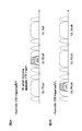
- FIG. 1 is a diagram illustrating an example of a method for transmitting uplink control information in an LTE system.
- the uplink control information (UCI) is transmitted via the uplink control channel (PUCCH) when there is no uplink user data (see FIG. 1A).
- uplink control information is transmitted when an uplink scheduling grant (UL grant) (DCI format 0/4) is transmitted via a downlink control channel (PDCCH) (that is, uplink user data exists). In the case), it is transmitted together with the uplink user data via the uplink shared channel (PUSCH) designated by the UL grant (see FIG. 1B).
- UL grant uplink scheduling grant
- PUSCH uplink shared channel
- the aperiodic channel state information which is one of the uplink control information (UCI)
- UCI uplink control information
- A-CSI trigger a non-periodic channel state information notification trigger
- FIG. 2 is a diagram illustrating an example of a method for transmitting uplink control information in the LTE-A system.
- the user terminal in order to increase the bandwidth by integrating a plurality of component carriers (CC), the user terminal is configured to be able to communicate in a plurality of serving cells of different component carriers.
- CC component carriers
- the SC-FDMA radio access scheme is being studied. For this reason, in uplink transmission, it is desirable to transmit from a single CC (that is, a single serving cell) in order to maintain the characteristics of uplink single carrier transmission.
- uplink control information For example, when UCI is transmitted via PUCCH, a serving cell of PCC (Primary Component Carrier) to which PUCCH is transmitted is selected. On the other hand, when UCI is transmitted together with user data via PUSCH, the serving cell of the CC associated with the UL grant is selected.
- PCC Primary Component Carrier
- the SCC associated with the UL grant ( Secondary component carrier)
- UCI including A-CSI is transmitted using the selected SCC.
- a PCC serving cell also referred to as a P cell
- UCI is transmitted using the selected P cell.
- the communication state such as the interference level is different for each serving cell. Therefore, in the aperiodic channel state information notification (Aperiodic CSI Reporting), it is preferable that the A-CSI of the downlink serving cell required on the network side among the plurality of serving cells can be flexibly notified.
- FIG. 3 is a diagram illustrating an example of an A-CSI transmission method in the LTE-A system.
- FIG. 3 when specifying at least one downlink serving cell on the network side, not only the A-CSI trigger but also bit information designating a predetermined serving cell is included in the UL grant (DCI format 0/4). It is possible to add. For example, as shown in FIG. 3, by adding 1 bit to the existing A-CSI trigger field (1 bit), in addition to whether or not A-CSI should be notified, the A-CSI of which downlink serving cell is It is being considered to specify what should be notified.
- the value of the 2-bit A-CSI trigger field (also referred to as CSI Request field) is “00”, it indicates that “A-CSI is not transmitted”. Further, when the value of the A-CSI trigger field is “01”, this indicates that “A-CSI is transmitted for the serving cell of the downlink CC corresponding to the uplink CC associated with the UL grant”. Further, when the value of the A-CSI trigger field is “10”, it indicates that “A-CSI for at least one serving cell specified as the first set by the higher layer signaling is transmitted”. Further, when the value of the A-CSI trigger field is “11”, it indicates that “A-CSI for at least one serving cell designated as the second set by the higher layer signaling is transmitted”.
- the A-CSI trigger is provided by notifying in advance at least one downlink serving cell constituting the first set and the second set by a higher control signal using higher layer signaling (for example, RRC signaling).
- higher layer signaling for example, RRC signaling
- the user terminal uses two serving cells (cells # 0 and # 1), it is assumed that the cell # 0 as the first set and the cell # 1 as the second set are notified in advance by the upper control signal.
- the value of the A-CSI trigger field included in the UL grant (format 0/4) is “10”
- the user terminal transmits the A-CSI of cell # 0 of the first set to the radio base station apparatus.
- the value of the A-CSI trigger field is “11”
- the user terminal notifies the A-CSI of the second set of cell # 1.
- the higher control signal notifies cell # 0 as the first set and cells # 0 and # 1 as the second set in advance.
- the value of the A-CSI trigger field included in the UL grant (format 0/4) is “10”
- the user terminal transmits the A-CSI of cell # 0 of the first set to the radio base station apparatus.
- the value of the A-CSI trigger field is “11”
- the user terminal notifies the A-CSI of the second set of cells # 0 and # 1 (see FIG. 4).
- the user terminal uses five serving cells (cells # 0 to # 4), cells # 0 and # 1 as the first set, cells # 2, # 3 and # as the second set by the higher control signal. 4 is notified in advance.
- the value of the A-CSI trigger field included in the UL grant (format 0/4) is “10”
- the user terminal wirelessly transmits the A-CSI of the first set of cells # 0 and # 1.
- the value of the A-CSI trigger field is “11”
- the user terminal notifies the A-CSI of the first set of cells # 2, # 3, and # 4.
- the downlink serving cell to which A-CSI should be notified from the user terminal can be specified only with two types of notification patterns. Therefore, for example, when the user terminal uses five serving cells, the A-CSI of the two cells of cells # 0 and # 1 is determined even if the A-CSI notification of only the cell # 1 is desired on the network side. There is a problem that the overhead of PUSCH for notifying A-CSI increases.
- a method of transmitting PDSCH / PUSCH allocation information (DL grant / UL grant) used in a plurality of serving cells using the PDCCH of one serving cell is being studied.
- a method of transmitting PDSCH / PUSCH allocation information used in a plurality of serving cells by a serving cell (for example, P cell) of one CC is also called cross-carrier scheduling.
- CIF carrier indicator field
- FIG. 5 is a diagram illustrating an example of CIF used in cross-carrier scheduling in the LTE-A system.
- CIF is a 3-bit bit string.
- the value of CIF is “000”, it indicates that PDSCH / PUSCH is assigned to cell # 0 (P cell).
- the same applies to the case where the CIF value is “001”, “010”, “011”, “100”.
- the CIF included in the DL grant indicates that the PDSCH is assigned to the serving cell identified by the CIF.
- the CIF included in the UL grant indicates that the PUSCH is allocated to the serving cell identified by the CIF. For example, when the CIF included in the received DL grant is “000”, the user terminal demodulates the PDSCH assigned to the cell # 0 using the DL grant. On the other hand, when the CIF included in the received UL grant is “000”, the user terminal transmits uplink data via the PUSCH assigned to the cell # 0.
- the user terminal uses a maximum of five serving cells. For this reason, three types of values (“101”, “110”, “111” in FIG. 5) among the eight types of CIF values are unused.
- the radio base station apparatus uses an identification field (CIF) that identifies an uplink serving cell to which an uplink shared channel (PUSCH) is allocated among a plurality of uplink serving cells and a user.
- An uplink scheduling grant (UL grant) including a request field (A-CSI trigger field) for requesting notification of aperiodic channel state information (A-CSI) from the terminal is transmitted via the downlink control channel (PDCCH). This is transmitted to the user terminal, and the user terminal notifies the radio base station apparatus of the A-CSI of the downlink serving cell specified by the combination of the identification field (CIF) and the request field (A-CSI trigger field).
- the radio base station apparatus uses the identification field (CIF) and the request field (A-CSI trigger field) more. Therefore, the user terminal can flexibly notify the aperiodic channel state information (A-CSI) of the downlink serving cell required on the network side.
- CIF identification field
- A-CSI trigger field request field
- the radio base station apparatus specifies at least one uplink serving cell among a plurality of uplink serving cells by using CIF.
- A-CSI is set using the A-CSI trigger field.
- the serving cell to be notified can be specified in more combinations.
- the designation by the combination of the CIF and the A-CSI trigger field is realized by a mapping table as shown in FIG. 6, FIG. 7, and FIG.
- this mapping table the CIF value and the identification information of the uplink serving cell to which the PUSCH is allocated are mapped, and the value of the A-CSI trigger field and at least one downlink serving cell to which the A-CSI is to be reported are mapped Is done.
- the PUSCH is assigned to the uplink serving cell identified by the CIF, at least one downlink serving cell for which A-CSI is to be notified is specified by the value of the A-CSI trigger field.
- a part of the uplink serving cell is also allocated to the CIF values (“101”, “110”, “111”) that have not been used before.
- the uplink serving cell to be assigned to a plurality of CIF values is preferably an uplink serving cell with high importance, such as a serving cell having a large number of P cell or PUSCH assignments. This is because when the PUSCH is assigned to the uplink serving cell having high importance, the A-CSI variation of the downlink serving cell required on the network side increases. In this way, by assigning highly important uplink serving cells to a plurality of CIF values, it is possible to increase the A-CSI notification pattern without increasing the number of bits of the A-CSI trigger field.
- any serving cell may be assigned to the CIF value, and the value assignment shown in FIGS. 6 to 9 is merely an example. Similarly, at least one serving cell may be assigned to the value of the A-CSI trigger field in any combination, and the value assignment shown in FIGS. 6 to 9 is merely an example. Also, the uplink serving cell and the downlink serving cell may be physically different serving cells, or one serving cell may be functionally distinguished.
- the present invention is not limited to this.
- the present invention can be appropriately applied to the case where the CIF and the A-CSI trigger field are included in the DL grant.
- FIG. 6 is a diagram for explaining an aperiodic channel state information notification method when a user terminal uses two serving cells.
- FIG. 6 illustrates an example in which the user terminal uses two serving cells of cell # 0 and cell # 1.
- the CIF value “000” indicates that the PUSCH is allocated to the cell # 0.
- the value “01” of the A-CSI trigger field should notify the A-CSI of the cell # 0 to which the PUSCH is assigned, and “10” is the cell # 1.
- “11” indicates that the A-CSI of both cells # 0 and # 1 should be notified.
- the CIF value “001” indicates that the PUSCH is assigned to the cell # 1, and when the PUSCH is assigned to the cell # 1, the serving cell to be notified of the A-CSI is indicated in the A-CSI trigger field. Indicates the value.
- the radio base station apparatus when the PUSCH is assigned to the serving cell identified by the CIF according to the assignment of the CIF and A-CSI trigger field values shown in FIG. A serving cell in which A-CSI is to be notified from the user terminal is specified using the CSI trigger field.
- the radio base station apparatus assigns the PUSCH for the user terminal to cell # 0 and requests the user terminal to notify the A-CSI of cell # 1, set “000” in the UL grant CIF, “10” is set in the UL grant A-CSI trigger field.
- the radio base station apparatus transmits a UL grant including the CIF and the A-CSI trigger field to the user terminal via the PDCCH.
- the PUSCH When the user terminal receives an UL grant with a CIF value of “000” and an A-CSI value of “10” from the radio base station via the PDCCH, the PUSCH is assigned to the cell # 0. It detects that the A-CSI of cell # 1 should be notified. The user terminal transmits the A-CSI of cell # 1 via the PUSCH assigned to cell # 0.
- the user terminal when the user terminal uses two serving cells, the user terminal is identified by the CIF with the A-CSI of the downlink serving cell specified by the combination of the CIF and the A-CSI trigger field included in the UL grant. It transmits via PUSCH allocated to the uplink serving cell.
- all notification patterns when the user terminal uses two serving cells can be covered by a combination of the CIF and the A-CSI trigger field. Therefore, the user terminal can reliably notify the A-CSI of the serving cell required on the network side in accordance with the designation from the radio base station apparatus.
- ⁇ 5 serving cell (first example)> 7 and 8 are diagrams for explaining a non-periodic channel state information notification method when a user terminal uses five serving cells.
- 7 and 8 show examples in which the user terminal uses five serving cells of cell # 0 to cell # 4.
- cell # 0 has shown the example which is a serving cell (P cell) of PCC of a user terminal.
- CIF values “000” to “100” indicate that PUSCH is allocated to cells # 0 to # 4, respectively.
- the CIF values “101” to “111” also indicate that the PUSCH is assigned to the cell # 0.
- the values “10” and “11” of the A-CSI trigger field indicate at least one downlink serving cell to be notified of A-CSI when PUSCH is assigned to the uplink serving cell identified by CIF.
- the radio base station apparatus uses the A-CSI trigger field from the user terminal when the PUSCH is assigned to the serving cell identified by the CIF according to the assignment of the CIF and A-CSI trigger field values shown in FIG. A downlink serving cell to be notified of A-CSI is specified.
- the CIF and A-CSI trigger field value assignment information shown in FIG. 7 may be notified in advance from the radio base station apparatus to the user terminal by a higher layer signaling higher control signal, or the radio base station apparatus and user It may be preset in both terminals.
- the cell # 0 which is the P cell among the cells # 0 to # 4, is assigned to the CIF value in an overlapping manner.
- the radio base station apparatus uses the CIF values “000”, “101”, “110”, and “111”.
- cell # 0 can be designated in duplicate.
- the radio base station apparatus uses a combination of CIF values “000”, “101”, “110”, “111” and A-CSI trigger field values “10” and “11” for a total of 8 You can specify different types of serving cells.
- the radio base station apparatus when the radio base station apparatus assigns the user terminal's PUSCH to the cell # 0 and requests the user terminal to notify the A-CSI of the cell # 3, the UL grant CIF includes “101”. "And" 11 "are set in the UL grant A-CSI trigger field.
- the radio base station apparatus transmits the UL grant to the user terminal via the PDCCH.
- the user terminal when the user terminal receives an UL grant with a CIF value of “101” and an A-CSI value of “11”, the PUSCH is assigned to cell # 0. Therefore, it is detected that the A-CSI of cell # 3 should be notified.
- the user terminal transmits the A-CSI of cell # 3 via the PUSCH assigned to cell # 0.
- the radio base station apparatus assigns the PUSCH to the P cell (cell # 0), as shown in FIG. 7, the CIF values “000”, “101”, “110”, “111” And a combination of the values “10” and “11” of the A-CSI trigger field, it is possible to specify a downlink serving cell to which a total of eight types of combinations of A-CSI should be notified. Therefore, the combination of the CIF value “000” and the A-CSI trigger field values “10” and “11” allows more downlink serving cells to be specified only in a total of two types of combinations than in the prior art. A downlink serving cell to which A-CSI should be notified can be specified in combination.
- the PUSCH has a higher probability of being assigned to the P cell. For this reason, when the PUSCH is assigned to the P cell, the user terminal can more flexibly notify the A-CSI of the downlink serving cell required on the network side by increasing the designated pattern of the downlink serving cell.
- FIG. 9 is a diagram for explaining an aperiodic channel state information notification method when a user terminal uses five serving cells.
- FIG. 9 shows an example in which the user terminal uses five serving cells of cell # 0 to cell # 4.
- FIG. 9 shows an example in which cell # 0 is the serving cell (P cell) of the PCC of the user terminal.
- the CIF and A-CSI trigger field value assignment information shown in FIG. 9 may be notified in advance from the radio base station apparatus to the user terminal by a higher layer signaling higher control signal, or the radio base station apparatus and user It may be preset in both terminals.
- CIF values “000” to “100” indicate that PUSCH is allocated to cells # 0 to # 4, respectively.
- the CIF value “101” indicates that the cell is assigned to cell # 0
- “110” indicates that the cell is assigned to cell # 1
- “111” indicates that the cell is assigned to cell # 2.
- the values “10” and “11” of the A-CSI trigger field indicate at least one downlink serving cell to which A-CSI is to be notified when the PUSCH is allocated to the uplink serving cell identified by the CIF value. Yes.
- the radio base station apparatus uses cell numbers “000” and “101” to duplicate cell # 0. Can be specified. As a result, the radio base station apparatus can designate a total of four types of serving cells by combining the CIF values “000” and “101” with the A-CSI trigger field values “10” and “11”. .
- the radio base station apparatus performs CIF values “001” and “110” and an A-CSI trigger field value “10”.
- a combination of “11” and “11” can specify a total of four types of downlink serving cells.
- PUSCH is assigned to cell # 2
- the downlink serving cell can be specified.
- the radio base station apparatus assigns four types of combinations of downlink serving cells to each of PUSCH assigned to cell # 0, cell # 1, and cell # 2. Can be specified. Therefore, when the PUSCH of any uplink serving cell is assigned, the downlink serving cell can be specified by a more flexible combination than the conventional method in which the downlink serving cell can be specified only by two types of combinations.
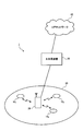
- the mobile communication system 1 including the user terminal 10 and the radio base station apparatus 20 will be described with reference to FIG.
- the user terminal 10 and the radio base station apparatus 20 support LTE-A.
- the mobile communication system 1 includes a radio base station apparatus 20 and a plurality of user terminals 10 (10 1 , 10 2 , 10 3 ,... 10 n , n communicating with the radio base station apparatus 20. Is an integer of n> 0).
- the radio base station apparatus 20 is connected to the higher station apparatus 30, and the higher station apparatus 30 is connected to the core network 40.
- the user terminal 10 can communicate with the radio base station apparatus 20 in the cell 50.
- the upper station device 30 includes, for example, an access gateway device, a radio network controller (RNC), a mobility management entity (MME), and the like, but is not limited thereto.
- the upper station apparatus 30 may be included in the core network 40.
- Each user terminal (10 1 , 10 2 , 10 3 ,... 10 n ) is an LTE-A terminal unless otherwise specified, but can also include an LTE terminal.
- the user terminal 10 performs radio communication with the radio base station apparatus 20, but more generally user equipment (UE: User Equipment) including both a mobile terminal and a fixed terminal may be used. .
- UE User Equipment
- OFDMA Orthogonal Frequency Division Multiple Access
- SC-FDMA single carrier-frequency division multiple access
- clustered DFT spread OFDM are applied to the uplink.
- OFDMA is a multi-carrier transmission scheme that performs communication by dividing a frequency band into a plurality of narrow frequency bands (subcarriers) and mapping data to each subcarrier.
- SC-FDMA is a single carrier transmission method that reduces interference between terminals by dividing a system band into bands each consisting of one or continuous resource blocks for each terminal, and a plurality of terminals using different bands.
- Clustered DFT-spread OFDM assigns non-contiguous clustered subcarrier groups (clusters) to one user terminal UE and applies discrete Fourier transform spread OFDM to each cluster, thereby increasing uplink multiples. This is a method for realizing connection.
- the communication channel configuration defined in LTE-A will be described.
- PDSCH shared by each user terminal 10 and downlink L1 / L2 control channels (PDCCH, PCFICH, PHICH) are used.
- User data including higher layer control signals
- Transmission data is included in this user data.
- the basic frequency block (CC) and scheduling information allocated to the user terminal 10 by the radio base station apparatus 20 are notified to the user terminal 10 through the downlink control channel.
- the upper control signal includes RRC signaling that notifies the user terminal 10 of addition / reduction of the number of carrier aggregations and an uplink radio access scheme (SC-FDMA / clustered DFT spread OFDM) applied to each component carrier. .
- RRC signaling that notifies the user terminal 10 of addition / reduction of the number of carrier aggregations and an uplink radio access scheme (SC-FDMA / clustered DFT spread OFDM) applied to each component carrier.
- SC-FDMA / clustered DFT spread OFDM uplink radio access scheme
- n CC specific to the basic frequency block may be simultaneously notified by RRC signaling.
- PUSCH For the uplink, PUSCH that is shared and used by each user terminal 10 and PUCCH that is an uplink control channel are used. User data is transmitted by this PUSCH. Downlink CSI (CQI / PMI / RI), ACK / NACK, etc. are transmitted by PUCCH. In addition, intra-subframe frequency hopping is applied in SC-FDMA.
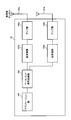
- the radio base station apparatus 20 includes transmission / reception antennas 201a and 201b, amplifier sections 202a and 202b, transmission / reception sections 203a and 203b, a baseband signal processing section 204, a call processing section 205, and a transmission path interface 206. Yes.
- User data transmitted in the downlink from the radio base station apparatus 20 to the user terminal 10 is input from the higher station apparatus 30 of the radio base station apparatus 20 to the baseband signal processing unit 204 via the transmission path interface 206.
- the baseband signal processing unit 204 performs PDCP layer processing such as sequence number assignment, user data division / combination, RLC layer transmission processing such as RLC (Radio Link Control) retransmission control transmission processing, MAC (Medium Access Control) Retransmission control, for example, HARQ transmission processing, scheduling, transmission format selection, channel coding, inverse fast Fourier transform (IFFT) processing, and precoding processing are performed.
- PDCP layer processing such as sequence number assignment, user data division / combination
- RLC layer transmission processing such as RLC (Radio Link Control) retransmission control transmission processing
- MAC (Medium Access Control) Retransmission control for example, HARQ transmission processing, scheduling, transmission format selection, channel coding, inverse fast Fourier transform (IFFT) processing, and precoding processing are performed.
- PDCP layer processing such as sequence number assignment, user data division / combination
- RLC layer transmission processing such as RLC (Radio Link Control) retransmission control transmission processing
- MAC (Medium Access Control) Retransmission control for example,
- the baseband signal processing unit 204 further notifies the user terminal 10 of control information for wireless communication in the cell 50 through a broadcast channel.
- the broadcast information for communication in the cell 50 includes, for example, system bandwidth in the uplink or downlink, identification information (Root Sequence Index) of a root sequence for generating a random access preamble signal in the PRACH, and the like. It is.
- the transmission / reception units 203a and 203b frequency-convert the baseband signal output from the baseband signal processing unit 204 into a radio frequency band.
- the RF signal is amplified by the amplifier unit 202 and output to the transmission / reception antennas 201a and 201b.
- the radio base station apparatus 20 receives the transmission wave transmitted by the user terminal 10 by the transmission / reception antennas 201a and 201b.
- Radio frequency signals received by the transmission / reception antennas 201a and 201b are amplified by the amplifier units 202a and 202b, converted into frequencies by the transmission / reception units 203a and 203b, converted into baseband signals, and input to the baseband signal processing unit 204.
- the baseband signal processing unit 204 performs FFT processing, IDFT processing, error correction decoding, MAC retransmission control reception processing, RLC layer, PDCP layer reception on user data included in the baseband signal received by uplink transmission. Process.
- the decoded signal is transferred to the higher station apparatus 30 via the transmission path interface 206.
- the call processing unit 205 performs call processing such as communication channel setting and release, state management of the radio base station apparatus 20, and radio resource management.
- the user terminal 10 includes a plurality of transmission / reception antennas 101a and 101b, amplifier units 102a and 102b, transmission / reception units 103a and 103b, a baseband signal processing unit 104, and an application unit 105.
- the radio frequency signals received by the transmission / reception antennas 101a and 101b are amplified by the amplifier units 102a and 102b, frequency-converted by the transmission / reception units 103a and 103b, and converted into baseband signals.
- the baseband signal is subjected to FFT processing, error correction decoding, retransmission control reception processing, and the like by the baseband signal processing unit 104.
- downlink user data is transferred to the application unit 105.
- the application unit 105 performs processing related to layers higher than the physical layer and the MAC layer. Also, the broadcast information in the downlink data is also transferred to the application unit 105.
- uplink user data is input from the application unit 105 to the baseband signal processing unit 104.
- the baseband signal processing unit 104 performs retransmission control (HARQ) transmission processing, channel coding, DFT processing, and IFFT processing.
- the transmission / reception unit 103 converts the baseband signal output from the baseband signal processing unit 104 into a radio frequency band. Thereafter, the signals are amplified by the amplifier units 102a and 102b and transmitted from the transmitting and receiving antennas 101a and 101b.
- HARQ retransmission control
- FIG. 13 is a functional block diagram of the baseband signal processing unit 204 and some higher layers included in the radio base station apparatus 20 according to the present embodiment.
- the baseband signal processing unit 204 mainly functions as a transmission processing unit. Indicates a block.
- FIG. 13 illustrates a base station configuration that can accommodate the number of M component carriers (CC # 1 to CC # M). Transmission data for the user terminal 10 under the control of the radio base station apparatus 20 is transferred from the higher station apparatus 30 to the radio base station apparatus 20.
- the control information generation unit 300 generates a higher control signal transmitted / received by higher layer signaling (RRC signaling).
- the upper control signal includes assignment information of the CIF value and the A-CSI trigger field value described with reference to FIGS. Further, the upper control signal may include a command for requesting addition / reduction of the component carrier CC. Further, the upper control signal may be generated for each user.
- the data generation unit 301 outputs the transmission data transferred from the higher station apparatus 30 as user data for each user.
- the component carrier selection unit 302 selects, for each user, a component carrier that is allocated to wireless communication with the user terminal 10. As described above, the addition / reduction of component carriers is notified from the radio base station apparatus 20 to the user terminal 10 by RRC signaling, and an application completion message is received from the user terminal 10. By receiving this application completion message, component carrier assignment (addition / deletion) is confirmed for the user, and the confirmed component carrier assignment is set in the component carrier selection unit 302 as component carrier assignment information. In accordance with the component carrier assignment information set for each user in component carrier selection section 302, the upper control signal and transmission data are distributed to channel coding section 303 of the corresponding component carrier.
- the scheduling unit 310 controls the allocation of component carriers to subordinate user terminals 10 according to the communication quality of the entire system band.
- the scheduling unit 310 determines addition / deletion of a component carrier to be allocated for communication with the user terminal 10.
- the control information generation unit 300 is notified of the determination result regarding the addition / deletion of the component carrier.
- a primary component carrier (PCC) is determined from among the component carriers selected for each user terminal.
- the PCC may be switched dynamically or quasi-statically.
- the scheduling unit 310 controls resource allocation in each component carrier. Scheduling is performed by distinguishing between LTE terminal users and LTE-A terminal users.
- the scheduling unit 310 receives transmission data and a retransmission instruction from the higher station apparatus 30 and receives a channel estimation value and a CQI of a resource block from a receiving unit that measures an uplink reception signal.
- the scheduling unit 310 performs scheduling of downlink allocation information, uplink allocation information, and upper and lower shared channel signals while referring to the retransmission instruction, the channel estimation value, and the CQI input from the higher station apparatus 30.
- the propagation path in mobile communication varies depending on the frequency due to frequency selective fading. Therefore, at the time of user data transmission, resource blocks with good communication quality are allocated to the user terminal 10 for each subframe (referred to as adaptive frequency scheduling).
- adaptive frequency scheduling a user terminal 10 with good channel quality is selected and assigned to each resource block. Therefore, the scheduling unit 310 allocates resource blocks that are expected to improve throughput using the CQI for each resource block fed back from each user terminal 10.
- the scheduling unit 310 controls the number of CCE aggregations according to the propagation path status with the user terminal 10. For cell edge users, the number of CCE aggregation is increased. Also, an MCS (coding rate, modulation scheme) that satisfies a predetermined block error rate with the allocated resource block is determined. Parameters satisfying the MCS (coding rate, modulation scheme) determined by the scheduling unit 310 are set in the channel coding units 303, 308, 312 and the modulation units 304, 309, 313.
- MCS coding rate, modulation scheme
- the baseband signal processing unit 204 includes a channel encoding unit 303, a modulation unit 304, and a mapping unit 305 corresponding to the maximum user multiplexing number N within one component carrier.
- the channel coding unit 303 channel-codes a shared data channel (PDSCH) composed of user data (including some higher control signals) output from the data generation unit 301 for each user.
- the modulation unit 304 modulates channel-coded user data for each user.
- the mapping unit 305 maps the modulated user data to radio resources.
- the baseband signal processing unit 204 includes a generation unit (downlink control information generation unit 306 and uplink control information generation unit 311) that generates control information using a predetermined DCI format from among a plurality of DCI formats.
- the plurality of DCI formats include a DCI format containing the UL grant (for example, DCI format 0/4) and a DCI format containing the DL grant (for example, the DCI format 1A).
- the downlink control information generation unit 306 generates downlink shared data channel control information for controlling PDSCH using a DCI format (for example, DCI format 1A) containing DL grant.
- the downlink shared data channel control information is generated for each user. Further, the downlink shared data channel control information includes an identification field (CIF) that identifies an uplink serving cell to which the PDSCH is assigned.
- CIF identification field
- the uplink control information generation unit 311 generates uplink shared data channel control information for controlling PUSCH using a DCI format (for example, DCI format 0/4) containing UL grant.
- the uplink shared data channel control information is generated for each user. Further, the uplink shared data channel control information includes an identification field (CIF) for identifying an uplink serving cell to which a PUSCH is assigned.
- CIF identification field
- the uplink shared data channel control information includes a request field (A-CSI trigger field) for requesting aperiodic channel state information (A-CSI).
- a value may be set in the A-CSI trigger field according to whether or not the notification of A-CSI from the user terminal 10 is requested. Further, a value may be set in the A-CSI trigger field according to the combination of downlink serving cells for which A-CSI is to be notified from the user terminal 10. For example, when the A-CSI notification from the user terminal 10 is not requested, “00” is set in the A-CSI trigger field, and when the A-CSI notification from the user terminal 10 is requested, the user terminal 10 “01”, “10”, and “11” are set according to the combination of downlink serving cells to which A-CSI is to be notified.
- the uplink shared data channel control information includes an RA flag, allocation information indicating the number of resource blocks and resource block position determined for each user terminal, modulation scheme, coding rate, redundancy version, new data or reproduction data , A transmission power control command for PUSCH, a cyclic shift (CS for DMRS) of a demodulation reference signal, a CQI request, an A-SRSF, a PMI / RI, and the like.
- RA flag allocation information indicating the number of resource blocks and resource block position determined for each user terminal, modulation scheme, coding rate, redundancy version, new data or reproduction data , A transmission power control command for PUSCH, a cyclic shift (CS for DMRS) of a demodulation reference signal, a CQI request, an A-SRSF, a PMI / RI, and the like.
- the baseband signal processing unit 204 includes a downlink common channel control information generation unit 307 that generates downlink common control channel control information that is user common downlink control information.
- the baseband signal processing unit 204 includes a channel encoding unit 308 and a modulation unit 309 corresponding to the maximum user multiplexing number N in one component carrier.
- the channel coding unit 308 channel-codes the control information generated by the downlink control information generation unit 306 and the downlink common channel control information generation unit 307 for each user.
- Modulation section 309 modulates channel-coded downlink control information.
- the baseband signal processing unit 204 channel-encodes the generated uplink shared data channel control information for each user, and modulates the channel-encoded uplink shared data channel control information for each user. And a modulation unit 313.
- the reference signal generation unit 318 transmits a cell-specific reference signal (CRS) used for various purposes such as channel estimation, symbol synchronization, CQI measurement, mobility measurement, and the like in the resource block (RB). Multiplexed by TDM and transmitted. Further, the reference signal generation unit 318 transmits a downlink demodulation reference signal (UE specific RS).
- CRS cell-specific reference signal
- UE specific RS downlink demodulation reference signal
- the downlink / uplink control information modulated for each user by the modulation units 309 and 313 is multiplexed by the control channel multiplexing unit 314 and further interleaved by the interleaving unit 315.
- the control signal output from the interleaving unit 315 and the user data output from the mapping unit 305 are input to the IFFT unit 316 as downlink channel signals.
- the downlink reference signal is input to the IFFT unit 316.
- the IFFT unit 316 performs inverse fast Fourier transform on the downlink channel signal and downlink reference signal to convert the frequency domain signal into a time-series signal.
- the cyclic prefix insertion unit 317 inserts a cyclic prefix into the time-series signal of the downlink channel signal.
- the cyclic prefix functions as a guard interval for absorbing the difference in multipath propagation delay.
- the transmission data to which the cyclic prefix is added is sent to the transmission / reception unit 203.
- FIG. 14 is a functional block diagram of the baseband signal processing unit 104 included in the user terminal 10, and shows functional blocks of the LTE-A terminal that supports LTE-A. Note that the user terminal 10 is configured to be able to perform wireless communication using a plurality of serving cells of different component carriers (CC).
- CC component carriers
- the CP is removed by the CP removal unit 401 from the downlink signal received from the radio base station apparatus 20 as reception data.
- the downlink signal from which the CP is removed is input to the FFT unit 402.
- the FFT unit 402 performs fast Fourier transform (FFT) on the downlink signal to convert it from a time domain signal to a frequency domain signal, and inputs it to the demapping unit 403.
- the demapping unit 403 demaps the downlink signal, and extracts multiplex control information, user data, and higher control signal in which a plurality of control information is multiplexed from the downlink signal. Note that the demapping process by the demapping unit 403 is performed based on a higher control signal input from the application unit 105.
- the multiplex control information output from the demapping unit 403 is deinterleaved by the deinterleaving unit 404.
- the baseband signal processing unit 104 includes a control information demodulation unit 405 that demodulates downlink / uplink control information, a data demodulation unit 406 that demodulates downlink shared data, and a channel estimation unit 407.
- the control information demodulator 405 includes a common control channel control information demodulator 405a that demodulates downlink common control channel control information from the downlink control channel, and an uplink shared data channel by blind decoding the search space from the downlink control channel.
- the data demodulator 406 includes a downlink shared data demodulator 406a that demodulates user data and higher control signals, and a downlink shared channel data demodulator 406b that demodulates downlink shared channel data.
- the common control channel control information demodulator 405a receives common control channel control information, which is common control information for users through blind decoding processing, demodulation processing, channel decoding processing, and the like of the common search space of the downlink control channel (PDCCH). Take out.
- the common control channel control information includes downlink channel quality information (CQI), is input to the mapping unit 415, and is mapped as part of transmission data to the radio base station apparatus 20.
- CQI downlink channel quality information
- the uplink shared data channel control information demodulator 405b performs user-specific uplink shared data channel control information (for example, by performing blind decoding processing, demodulation processing, channel decoding processing, etc.) on the user dedicated search space of the downlink control channel (PDCCH). , UL Grant).
- the demodulated uplink shared data channel control information is input to the mapping unit 415 and used for uplink shared data channel (PUSCH) control.
- the downlink shared data channel control information demodulating section 405c performs user-specific downlink shared data channel control information (for example, blind decoding processing, demodulation processing, channel decoding processing, etc.) for the user dedicated search space of the downlink control channel (PDCCH). , DL Grant).
- the demodulated downlink shared data channel control information is input to the downlink shared data demodulation section 406 and used for controlling the downlink shared data channel (PDSCH).
- the downlink shared data demodulator 406a acquires user data and higher control information based on the downlink shared data channel control information input from the downlink shared data channel control information demodulator 405c. Upper control information (including mode information) is output to channel estimation section 407.
- the downlink common channel data demodulator 406b demodulates the uplink common channel data based on the uplink shared data channel control information input from the uplink shared data channel control information demodulator 405b.
- the channel estimation unit 407 performs channel estimation using a reference signal unique to the user terminal or a common reference signal.
- the estimated channel fluctuation is output to the common control channel control information demodulator 405a, the uplink shared data channel control information demodulator 405b, the downlink shared data channel control information demodulator 405c, and the downlink shared data demodulator 406a.
- These demodulation units perform demodulation processing using the estimated channel fluctuation and demodulation reference signal.
- the baseband signal processing unit 104 includes a data generation unit 411, a channel encoding unit 412, a modulation unit 413, a DFT unit 414, a mapping unit 415, an IFFT unit 416, a CP insertion unit 417, a channel state as functional blocks of a transmission processing system.
- An information generation unit 418 is provided.
- the data generation unit 411 generates transmission data from the bit data input from the application unit 105.
- the channel coding unit 412 performs channel coding processing such as error correction on the transmission data, and the modulation unit 413 modulates the channel coded transmission data with QPSK or the like.
- the DFT unit 414 performs discrete Fourier transform on the modulated transmission data.
- Mapping section 415 maps each frequency component of the data symbol after DFT to a subcarrier position designated by radio base station apparatus 20.
- the IFFT unit 416 performs inverse fast Fourier transform on input data corresponding to the system band to convert it into time series data, and the CP insertion unit 417 inserts a cyclic prefix into the time series data at data delimiters.
- the channel state information generation unit 418 generates channel state information (CSI (CQI / PMI / RI)) periodically or aperiodically based on the UL grant demodulated by the uplink shared data channel control information demodulation unit 405b. .
- CSI channel state information
- the channel state information generation unit 418 generates A-CSI when the UL grant A-CSI trigger field requests notification of aperiodic channel state information (A-CSI). Further, when the user terminal 10 performs wireless communication using a plurality of serving cells, the channel state information generation unit 418, for example, as described with reference to FIGS. 6, 8, and 10, CIF and A-CSI A-CSI of a downlink serving cell designated by a combination of trigger fields is generated.
- the serving cell (see FIGS. 6, 8, and 10) assigned to each value of the CIF and A-CSI trigger fields is transmitted in advance from the radio base station 20 to the user terminal 10 (for example, RRC). Signaling) or may be fixedly set in the user terminal 10.
Landscapes
- Engineering & Computer Science (AREA)
- Signal Processing (AREA)
- Computer Networks & Wireless Communication (AREA)
- Quality & Reliability (AREA)
- Mobile Radio Communication Systems (AREA)
Abstract
ユーザ端末が異なるコンポーネントキャリアの複数のサービングセルを用いて無線通信を行う場合に、複数のサービングセルのうちネットワーク側で必要とされるサービングセルの非周期的チャネル状態情報を柔軟に通知すること。無線基地局装置が、複数の上りサービングセルのうち上りリンク共有チャネルが割り当てられた上りサービングセルを識別する識別フィールドとユーザ端末からの非周期的チャネル状態情報の通知を要求する要求フィールドとを含む上りリンクスケジューリンググラントを、下りリンク制御チャネルを介して前記ユーザ端末に送信し、前記ユーザ端末が、前記識別フィールドと前記要求フィールドとの組み合わせによって指定された下りサービングセルの非周期的チャネル状態情報を、前記上りリンク共有チャネルを介して前記無線基地局装置に通知する。
Description
本発明は、次世代無線通信システムにおける非周期的チャネル状態情報通知方法、無線基地局装置、ユーザ端末に関する。
UMTS(Universal Mobile Telecommunications System)ネットワークにおいて、更なる高速データレート、低遅延などを目的としてロングタームエボリューション(LTE:Long Term Evolution)が検討されている(非特許文献1)。LTEではマルチアクセス方式として、下りリンクではOFDMA(Orthogonal Frequency Division Multiple Access)をベースとした方式を用い、上りリンクではSC-FDMA(Single Carrier Frequency Division Multiple Access)をベースとした方式を用いている。
LTEシステムにおいて、上りリンク信号は適切な無線リソースにマッピングされてユーザ端末から無線基地局装置に送信される。具体的には、上りユーザデータは、上りリンク共有チャネル(PUSCH:Physical Uplink Shared Channel)を用いて送信される。また、上りリンク制御情報(UCI:Uplink Control Information)は、上りユーザデータと共に送信する場合はPUSCHを用いて、単独で送信する場合は上りリンク制御チャネル(PUCCH:Physical Uplink Control Channel)を用いて送信される。
上りリンク制御情報(UCI)には、下りリンク共有チャネル(PDSCH:Physical Downlink Shared Channel))に対する送達確認(ACK/NACK)、スケジューリング要求、チャネル状態情報(CSI:Channel State Information)等が含まれる(例えば、非特許文献2)。チャネル状態情報(以下、CSIという)は、下りリンクの瞬時のチャネル状態に基づく情報であり、例えば、チャネル品質情報(CQI)、プリコーディングマトリックス指標(PMI)、ランク指標(RI)などである。このCSIは、周期的又は非周期的に、ユーザ端末から無線基地局装置に通知される。
非周期的チャネル状態情報(Aperiodic CSI)は、無線基地局装置からのトリガに応じて、ユーザ端末から当該無線基地局に通知される。このトリガ(Aperiodic CSI triggering)は、下りリンク制御チャネル(PDCCH:Physical Downlink Control Channel)で送信される上りリンクスケジューリンググラント(以下、UL(Uplink)グラントという)(DCIフォーマット0/4)に含まれている。ユーザ端末は、当該ULグラントに含まれるトリガに従って、当該ULグラントで指定されたPUSCHを用いて、非周期チャネル状態情報(以下、A-CSIという)を通知する。このようなA-CSIの通知は、非周期的チャネル状態情報通知(Aperiodic CSI(CQI/PMI/RI) Reporting)とも呼ばれる。
3GPP, TR25.912 (V7.1.0), "Feasibility study for Evolved UTRA and UTRAN", Sept. 2006
3GPP, TS36.212 (V.9.3.0), "Multiplexing and channel coding", Nov.2010
ところで、3GPPにおいては、更なる広帯域化及び高速化を目的として、LTEシステムの後継システム(例えば、LTE-Advanced(LTE-A)システム)も検討されている。LTE-Aシステムでは、LTEシステムとの後方互換性(Backward compatibility)を保ちながら広帯域化を図ることが望ましい。そこで、LTE-Aシステムでは、LTEシステムで使用可能な帯域(例えば、20MHz)を有する基本周波数ブロック(コンポーネントキャリア(CC:Component Carrier)とし、複数のコンポーネントキャリアを統合することにより広帯域化(例えば、5つのCCが統合された場合、100MHz)を図ることが検討されている。
このようなLTE-Aシステムにおいては、一つのコンポーネントキャリア(CC)に対して少なくとも一つのセルが設けられ、ユーザ端末は、異なるコンポーネントキャリア(CC)の複数のセルにおいて通信できるように構成される。なお、各コンポーネントキャリア(CC)においてユーザ端末が主たる通信を行う一つのセルが、サービングセルとも称される。このように、LTE-Aシステムにおいては、ユーザ端末が、異なるコンポーネントキャリアの複数のサービングセルにおいて無線通信を行うことにより、システム帯域の広帯域化を実現する。
以上のようなLTE-Aシステムにおいて、ユーザ端末が異なるコンポーネントキャリア(CC)の複数のサービングセルにおいて無線通信を行う場合、サービングセル毎に干渉レベルなどの通信状態が異なることとなる。したがって、LTE-Aシステムにおいて、上述の非周期的チャネル状態情報通知(Aperiodic CSI Reporting)を行う場合には、複数のサービングセルのうち、ネットワーク側で必要とされる下りサービングセルの非周期的チャネル状態情報(A-CSI)を柔軟に通知可能とすることが望まれていた。
本発明はかかる点に鑑みてなされたものであり、ユーザ端末が異なるコンポーネントキャリアの複数のサービングセルを用いて無線通信を行う場合に、複数のサービングセルのうちネットワーク側で必要とされる下りサービングセルの非周期的チャネル状態情報を柔軟に通知可能な非周期的チャネル状態情報通知方法、無線基地局装置及びユーザ端末を提供することを目的とする。
本発明の非周期的チャネル状態通知方法は、複数の上りサービングセルのうち上りリンク共有チャネルが割り当てられた上りサービングセルを識別する識別フィールドとユーザ端末からの非周期的チャネル状態情報の通知を要求する要求フィールドとを含む上りリンクスケジューリンググラントを、下りリンク制御チャネルを介して無線基地局装置が前記ユーザ端末に送信するステップと、前記ユーザ端末が、前記識別フィールドと前記要求フィールドとの組み合わせによって指定された下りサービングセルの非周期的チャネル状態情報を、前記上りリンク共有チャネルを介して前記無線基地局装置に通知するステップと、を具備することを特徴とする。
この構成によれば、ユーザ端末が異なるコンポーネントキャリアの複数のサービングセルにおいて無線通信を行う場合に、識別フィールドと要求フィールドを用いてより多くの組み合わせで下りサービングセルを指定できるので、ユーザ端末は、ネットワーク側で必要とされる下りサービングセルの非周期的チャネル状態情報を柔軟に通知できる。
本発明の無線基地局装置は、複数の上りサービングセルのうち上りリンク共有チャネルが割り当てられた上りサービングセルを識別する識別フィールドとユーザ端末からの非周期的チャネル状態情報の通知を要求する要求フィールドとを含む上りリンクスケジューリンググラントを生成する生成部と、前記上りリンクスケジューリンググラントを下りリンク制御チャネルを介して前記ユーザ端末に送信する送信部と、を具備し、前記生成部は、前記識別フィールドと前記要求フィールドとの組み合わせによって、前記ユーザ端末から非周期的チャネル状態情報が通知されるべき少なくとも一つの下りサービングセルを指定することを特徴とする。
本発明のユーザ端末は、複数の上りサービングセルのうち上りリンク共有チャネルが割り当てられた上りサービングセルを識別する識別フィールドとユーザ端末からの非周期的チャネル状態情報の通知を要求する要求フィールドとを含む上りリンクスケジューリンググラントを、下りリンク制御チャネルを介して無線基地局装置から受信する受信部と、前記識別フィールドと前記要求フィールドとの組み合わせによって指定された下りサービングセルの非周期的チャネル状態情報を、前記上りリンク共有チャネルを介して前記無線基地局装置に通知する送信部と、を具備することを特徴とする。
本発明によれば、ユーザ端末が異なるコンポーネントキャリアの複数のサービングセルを用いて無線通信を行う場合に、複数のサービングセルのうちネットワーク側で必要とされる下りサービングセルの非周期的チャネル状態情報を柔軟に通知できる。
図1は、LTEシステムにおける上りリンク制御情報の送信方法の一例を示す図である。上述したように、上りリンク制御情報(UCI)は、上りユーザデータがない場合には、上りリンク制御チャネル(PUCCH)を介して送信される(図1A参照)。
一方、上りリンク制御情報(UCI)は、上りリンクスケジューリンググラント(ULグラント)(DCIフォーマット0/4)が下りリンク制御チャネル(PDCCH)を介して送信された場合(すなわち、上りユーザデータが存在する場合)には、当該ULグラントで指定された上りリンク共有チャネル(PUSCH)を介して上りユーザデータとともに送信される(図1B参照)。
例えば、上りリンク制御情報(UCI)の一つである非周期的チャネル状態情報(A-CSI)は、非周期的チャネル状態情報通知のトリガ(以下、A-CSIトリガという)がULグラント(DCIフォーマット0/4)に含まれているため、当該ULグラントに関連付けられたPUSCHを介して送信される。
図2は、LTE-Aシステムにおける上りリンク制御情報の送信方法の一例を示す図である。LTE-Aシステムでは、複数のコンポーネントキャリア(CC)の統合によって広帯域化を図るため、ユーザ端末は、異なるコンポーネントキャリアの複数のサービングセルにおいて通信できるように構成される。一方で、LTE-Aシステムの上りリンク伝送においては、SC-FDMAの無線アクセス方式の適用が検討されている。このため、上りリンク伝送では、上りシングルキャリア送信の特性を維持するために単一のCC(すなわち、単一のサービングセル)から送信することが望ましい。
上りリンク伝送を単一のCCで行う場合には、上りリンク制御情報(UCI)を送信するために、特定のCCのサービングセルを選択することが要求される。例えば、UCIが、PUCCHを介して送信される場合は、PUCCHが送信されるPCC(Primary Component Carrier)のサービングセルが選択される。一方、UCIが、PUSCHを介してユーザデータとともに送信される場合、ULグラントに関連付けられたCCのサービングセルが選択される。
より具体的には、図2Aに示すように、ユーザ端末からのA-CSIの通知が要求される場合(ULグラントにA-CSIトリガが含まれる場合)、当該ULグラントに関連付けられたSCC(Secondary Component Carrier))のサービングセル(Sセルとも呼ばれる)が選択され、選択されたSCCを用いてA-CSIを含むUCIが送信される。一方、図2Bに示すように、ユーザ端末からのA-CSIの通知が要求されない場合、PCCのサービングセル(Pセルとも呼ばれる)が選択され、選択されたPセルを用いてUCIが送信される。
また、LTE-Aシステムにおいては、ユーザ端末が異なるCCの複数のサービングセルにおいて無線通信を行う場合、サービングセル毎に干渉レベルなどの通信状態が異なることとなる。したがって、非周期的チャネル状態情報通知(Aperiodic CSI Reporting)においては、複数のサービングセルのうちネットワーク側で必要とされる下りサービングセルのA-CSIを柔軟に通知可能とすることが好ましい。
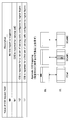
図3は、LTE-AシステムにおけるA-CSIの送信方法の一例を示す図である。図3に示すように、ネットワーク側において少なくとも一つの下りサービングセルを指定しようとする場合、ULグラント(DCIフォーマット0/4)に、A-CSIトリガだけでなく、所定のサービングセルを指定するビット情報を追加することが考えられる。例えば、図3に示すように、既存のA-CSIトリガフィールド(1ビット)に1ビットを追加することにより、A-CSIを通知すべきか否かに加えて、どの下りサービングセルのA-CSIを通知すべきかを指定することが検討されている。
例えば、図3では、2ビットのA-CSIトリガフィールド(CSI Request fieldともいう)の値が“00”である場合、“A-CSIを送信しない”ことを示す。また、A-CSIトリガフィールドの値が“01”である場合、“ULグラントに関連付けられた上りCCに対応する下りCCのサービングセルについてのA-CSIを送信する”ことを示す。また、A-CSIトリガフィールドの値が“10”である場合、“ハイヤーレイヤシグナリングにより第1のセットとして指定された少なくとも一つのサービングセルについてのA-CSIを送信する”ことを示す。また、A-CSIトリガフィールの値が“11”である場合、“ハイヤーレイヤシグナリングにより第2のセットとして指定された少なくとも一つのサービングセルについてのA-CSIを送信する”ことを示す。
上述の例においては、ハイヤーレイヤシグナリング(例えば、RRCシグナリング)を用いた上位制御信号により第1のセット及び第2のセットを構成する少なくとも一つの下りサービングセルを予め通知することにより、A-CSIトリガフィールドの値が“10”及び“11”の場合に、2種類の通知パターンを実現する。
例えば、ユーザ端末が2つのサービングセル(セル#0及び#1)を用いる場合、上位制御信号により、第1のセットとしてセル#0、第2のセットとしてセル#1が予め通知されるとする。この場合、ユーザ端末は、ULグラント(フォーマット0/4)に含まれるA-CSIトリガフィールドの値が“10”であれば、第1のセットのセル#0のA-CSIを無線基地局装置に通知する。一方、ユーザ端末は、A-CSIトリガフィールドの値が“11”であれば、第2のセットのセル#1のA-CSIを通知する。
また、ユーザ端末が2つのサービングセル(セル#0及び#1)を用いる場合、上位制御信号により、第1のセットとしてセル#0、第2のセットとしてセル#0及び#1が予め通知されるとする。この場合、ユーザ端末は、ULグラント(フォーマット0/4)に含まれるA-CSIトリガフィールドの値が“10”であれば、第1のセットのセル#0のA-CSIを無線基地局装置に通知する。一方、ユーザ端末は、A-CSIトリガフィールドの値が“11”であれば、第2のセットのセル#0及び#1のA-CSIを通知する(図4参照)。
また、ユーザ端末が5つのサービングセル(セル#0~#4)を用いる場合、上位制御信号により、第1のセットとしてセル#0及び#1、第2のセットとしてセル#2、#3及び#4が予め通知されるとする。この場合、ユーザ端末は、ULグラント(フォーマット0/4)に含まれるA-CSIトリガフィールドの値が“10”であれば、第1のセットのセル#0及び#1のA-CSIを無線基地局装置に通知する。一方、ユーザ端末は、A-CSIトリガフィールドの値が“11”であれば、第1のセットのセル#2、#3及び#4のA-CSIを通知する。
しかしながら、上述の例においては、2種類の通知パターンでしかユーザ端末からA-CSIが通知されるべき下りサービングセルを指定することができない。したがって、例えば、ユーザ端末が5つのサービングセルを用いる場合、ネットワーク側においてセル#1のみのA-CSIの通知を望む場合であっても、セル#0及び#1の2つのセルのA-CSIを通知しなければならず、A-CSIを通知するPUSCHのオーバヘッドが増加するという問題点があった。
ところで、LTE-Aシステムでは、複数のサービングセルで用いられるPDSCH/PUSCHの割り当て情報(DLグラント/ULグラント)を、一つのサービングセルのPDCCHで送信する方法が検討されている。このように、複数のサービングセルで用いられるPDSCH/PUSCHの割り当て情報を一つのCCのサービングセル(例えば、Pセル)によって送信する方法は、クロスキャリアスケジューリングとも呼ばれる。
このようなクロスキャリアスケジューリングにおいては、どのサービングセルにPDSCH/PUSCHが割り当てられているかを識別する必要がある。そこで、PDSCH/PUSCHが割り当てられたサービングセルを識別するキャリアインジケータフィールド(CIF:Carrier Indicator Field)(以下、CIFという)をDLグラント/ULグラントに含めることが検討されている。
図5は、LTE-Aシステムのクロスキャリアスケジューリングで用いられるCIFの一例を示す図である。なお、図5においては、5つのサービングセル(セル#0~#4)が用いられる場合を想定している。図5に示すように、CIFは、3ビットのビット列である。CIFの値が“000”である場合、PDSCH/PUSCHがセル#0(Pセル)に割り当てられることを示す。同様に、CIFの値が“001”、“010”、“011”、“100”の場合についても同様である。
なお、DLグラントに含まれるCIFは、PDSCHが当該CIFによって識別されるサービングセルに割り当てられることを示す。一方、ULグラントに含まれるCIFは、PUSCHが当該CIFによって識別されるサービングセルに割り当てられることを示す。例えば、ユーザ端末は、受信したDLグラントに含まれるCIFが“000”である場合、セル#0に割り当てられたPDSCHを、DLグラントを用いて復調する。一方、ユーザ端末は、受信したULグラントに含まれるCIFが“000”である場合、セル#0に割り当てられたPUSCHを介して上りデータを送信する。
ここで、LTE-Aシステムでは、ユーザ端末は最大5つのサービングセルを用いることが想定されている。このため、8種類のCIFの値のうち3種類の値(図5では、“101”、“110”、“111”)は未使用である。本発明者は、CIFに未使用の値があることに着目し、このCIFとA-CSIトリガフィールドとの組み合わせによって、ネットワーク側で必要とされるサービングセルのA-CSIを指定することを見出した。
本発明に係る非周期的チャネル状態通知方法においては、無線基地局装置が、複数の上りサービングセルのうちで上りリンク共有チャネル(PUSCH)が割り当てられた上りサービングセルを識別する識別フィールド(CIF)とユーザ端末からの非周期的チャネル状態情報(A-CSI)の通知を要求する要求フィールド(A-CSIトリガフィールド)とを含む上りスケジューリンググラント(ULグラント)を、下りリンク制御チャネル(PDCCH)を介してユーザ端末に送信し、ユーザ端末が、識別フィールド(CIF)と要求フィールド(A-CSIトリガフィールド)との組み合わせによって指定された下りサービングセルのA-CSIを無線基地局装置に通知する。
これにより、ユーザ端末が異なるコンポーネントキャリア(CC)の複数のサービングセルにおいて無線通信を行う場合に、無線基地局装置は、識別フィールド(CIF)と要求フィールド(A-CSIトリガフィールド)を用いてより多くの組み合わせで下りサービングセルを指定できるので、ユーザ端末は、ネットワーク側で必要とされる下りサービングセルの非周期的チャネル状態情報(A-CSI)を柔軟に通知できる。
また、本発明に係る非周期的チャネル状態通知方法においては、A-CSIトリガフィールドを用いて、CIFによって指定された上りサービングセルにPUSCHが割り当てられる場合に、ユーザ端末からA-CSIが通知されるべき少なくとも一つの下りサービングセルを指定する。さらに、本発明に係る非周期的チャネル状態通知方法においては、無線基地局装置は、CIFを用いて、複数の上りサービングセルのうち少なくとも一つの上りサービングセルを重複して指定する。
これにより、CIFを用いて少なくとも一つの上りサービングセルが重複して指定されるので、重複して指定された上りサービングセルにPUSCHが割り当てられる場合に、A-CSIトリガフィールドを用いて、A-CSIが通知されるべきサービングセルをより多くの組み合わせで指定できる。
なお、後に詳述するように、CIFとA-CSIトリガフィールドとの組み合わせによる指定は、図6、図7、図9に示すようなマッピングテーブルによって実現される。このマッピングテーブルにおいては、CIFの値とPUSCHが割り当てられる上りサービングセルの識別情報とがマッピングされるとともに、A-CSIトリガフィールドの値とA-CSIが通知されるべき少なくとも一つの下りサービングセルとがマッピングされる。この結果、CIFによって識別される上りサービングセルにPUSCHが割り当てられた場合に、A-CSIが通知されるべき少なくとも一つの下りサービングセルがA-CSIトリガフィールドの値によって指定されることとなる。
特に、図7及び図9においては、従来未使用であったCIFの値(“101”、“110”、“111”)にも、上りサービングセルの一部が重複して割り当てられている。このように、一部の上りサービングセルをCIFの複数の値に割り当てると、当該一部の上りサービングセルにPUSCHが割り当てられた場合のA-CSIの通知パターンを増加させることができる。CIFの複数の値に割り当てるべき上りサービングセルとしては、例えば、PセルやPUSCHの割り当て回数が多いサービングセル等、重要度の高い上りサービングセルが好ましい。重要度の高い上りサービングセルにPUSCHが割り当てられる場合には、ネットワーク側において必要とされる下りサービングセルのA-CSIのバリエーションも増えるからである。このように、重要度の高い上りサービングセルをCIFの複数の値に割り当てることにより、A-CSIトリガフィールドのビット数を増加させずとも、A-CSIの通知パターンを増加させることができる。
以下の説明においては、CIFが3ビットの例を示すが、CIFのビット数はこれに限れられるものではない。同様に、A-CSIトリガフィールドが2ビットの例を示すが、A-CSIトリガフィールドのビット数もこれに限られるものではない。なお、以下に説明において、CIFの値にはどのサービングセルが割り当てられてもよく、図6~9に示す値の割り当ては一例にすぎない。同様に、A-CSIトリガフィールドの値には、少なくとも一つのサービングセルがどのような組み合わせで割り当てられてもよく、図6~9に示す値の割り当ては一例にすぎない。また、上りサービングセルと下りサービングセルとは、物理的に異なるサービングセルであってもよいし、一つのサービングセルが機能的に区別されるものであってもよい。
また、以下の説明においては、CIFとA-CSIトリガフィールドとをULグラントに含める場合を説明するが、これに限られるものではない。例えば、CIFとA-CSIトリガフィールドとをDLグラントに含める場合にも適宜適用可能である。
<2サービングセルの場合>
図6は、ユーザ端末が2つのサービングセルを用いる場合の非周期的チャネル状態情報通知方法を説明するための図である。図6では、ユーザ端末が、セル#0及びセル#1の2つのサービングセルを用いる例を示している。
図6は、ユーザ端末が2つのサービングセルを用いる場合の非周期的チャネル状態情報通知方法を説明するための図である。図6では、ユーザ端末が、セル#0及びセル#1の2つのサービングセルを用いる例を示している。
図6に示すように、CIFの値“000”は、セル#0にPUSCHが割り当てられることを示している。セル#0にPUSCHが割り当てられた場合に、A-CSIトリガフィールドの値“01”は、PUSCHが割り当てられたセル#0のA-CSIを通知すべきこと、“10”は、セル#1のA-CSIを通知すべきこと、“11”はセル#0及び#1の双方のA-CSIを通知すべきことを示す。同様に、CIFの値“001”は、セル#1にPUSCHが割り当てられることを示し、セル#1にPUSCHが割り当てられた場合にA-CSIが通知されるべきサービングセルをA-CSIトリガフィールドの値を示す。
ユーザ端末が2つのサービングセルを用いる場合、無線基地局装置は、図6に示すCIFとA-CSIトリガフィールドの値の割り当てに従って、CIFで識別されるサービングセルにPUSCHが割り当てられた場合に、A-CSIトリガフィールドを用いて、ユーザ端末からA-CSIが通知されるべきサービングセルを指定する。
例えば、無線基地局装置が、ユーザ端末に対するPUSCHをセル#0に割り当て、当該ユーザ端末にセル#1のA-CSIの通知を要求する場合、ULグラントのCIFに“000”を設定するとともに、ULグラントのA-CSIトリガフィールドに“10”を設定する。無線基地局装置は、CIFとA-CSIトリガフィールドを含むULグラントを、PDCCHを介してユーザ端末に送信する。
ユーザ端末は、無線基地局から、PDCCHを介して、CIFの値が“000”であり、A-CSIの値が“10”であるULグラントを受信した場合、PUSCHがセル#0に割り当てられており、セル#1のA-CSIを通知すべきであることを検出する。ユーザ端末は、セル#0に割り当てられたPUSCHを介してセル#1のA-CSIを送信する。
以上のように、ユーザ端末が2つのサービングセルを用いる場合、ユーザ端末は、ULグラントに含まれるCIFとA-CSIトリガフィールドとの組み合わせによって指定された下りサービングセルのA-CSIを、CIFで識別された上りサービングセルに割り当てられたPUSCHを介して送信する。特に、図6に示す例においては、CIFとA-CSIトリガフィールドの組み合わせにより、ユーザ端末が2セルのサービングセルを用いる場合の全ての通知パターンを網羅できる。したがって、ユーザ端末は、無線基地局装置からの指定に従って、ネットワーク側で必要とされるサービングセルのA-CSIを確実に通知できる。
<5サービングセル(第1例)>
図7及び図8は、ユーザ端末が5つのサービングセルを用いる場合の非周期的チャネル状態情報通知方法を説明するための図である。図7及び図8では、ユーザ端末が、セル#0~セル#4の5つのサービングセルを用いる例を示している。また、図7及び図8では、セル#0がユーザ端末のPCCのサービングセル(Pセル)である例を示している。
図7及び図8は、ユーザ端末が5つのサービングセルを用いる場合の非周期的チャネル状態情報通知方法を説明するための図である。図7及び図8では、ユーザ端末が、セル#0~セル#4の5つのサービングセルを用いる例を示している。また、図7及び図8では、セル#0がユーザ端末のPCCのサービングセル(Pセル)である例を示している。
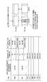
図7に示すように、CIFの値“000”~“100”は、それぞれ、セル#0~#4にPUSCHが割り当てられることを示している。また、図7においては、CIFの値“101”~“111”も、セル#0にPUSCHが割り当てられることを示している。A-CSIトリガフィールドの値“10”及び“11”は、CIFで識別された上りサービングセルにPUSCHが割り当てられる場合に、A-CSIが通知されるべき少なくとも一つの下りサービングセルが示されている。
無線基地局装置は、図7に示すCIFとA-CSIトリガフィールドの値の割り当てに従って、CIFで識別されるサービングセルにPUSCHが割り当てられた場合に、A-CSIトリガフィールドを用いて、ユーザ端末からA-CSIが通知されるべき下りサービングセルを指定する。なお、図7に示すCIFとA-CSIトリガフィールドの値の割り当て情報は、ハイヤーレイヤシグナリングの上位制御信号により無線基地局装置からユーザ端末に予め通知されてもよいし、無線基地局装置及びユーザ端末の双方に予め設定されていてもよい。
また、図7において、CIFの値には、セル#0~#4のうち、Pセルであるセル#0が重複して割り当てられる。図7に示す例においては、Pセルであるセル#0にPUSCHが割り当てられた場合に、無線基地局装置は、CIFの値“000”、“101”、“110”、“111”を用いて、セル#0を重複して指定できる。この結果、無線基地局装置は、CIFの値“000”、“101”、“110”、“111”と、A-CSIトリガフィールドの値“10”及び“11”との組み合わせによって、合計8種類の組み合わせのサービングセルを指定できる。
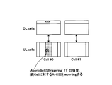
例えば、図8に示すように、無線基地局装置が、ユーザ端末のPUSCHをセル#0に割り当て、ユーザ端末にセル#3のA-CSIの通知を要求する場合、ULグラントのCIFに“101”を設定するとともに、ULグラントのA-CSIトリガフィールドに“11”を設定する。無線基地局装置は、当該ULグラントを、PDCCHを介してユーザ端末に送信する。
また、図8に示すように、ユーザ端末は、CIFの値が“101”であり、A-CSIの値が“11”であるULグラントを受信した場合、PUSCHがセル#0に割り当てられており、セル#3のA-CSIを通知すべきであることを検出する。ユーザ端末は、セル#0に割り当てられたPUSCHを介してセル#3のA-CSIを送信する。
以上のように、無線基地局装置は、PUSCHをPセル(セル#0)に割り当てた場合、図7に示すように、CIFの値“000”、“101”、“110”、“111”と、A-CSIトリガフィールドの値“10”及び“11”との組み合わせによって、合計8種類の組み合わせのA-CSIが通知されるべき下りサービングセルを指定できる。したがって、CIFの値“000”と、A-CSIトリガフィールドの値“10”及び“11”との組み合わせによって、合計2種類の組み合わせでしか下りサービングセルを指定できなかった従来よりも、より多くの組み合わせでA-CSIが通知されるべき下りサービングセルを指定できる。
特に、PUSCHはPセルに割り当てられる確立が高くなる。このため、PUSCHがPセルに割り当てられた場合に下りサービングセルの指定パターンを増加させることによって、ユーザ端末は、ネットワーク側で必要とされる下りサービングセルのA-CSIをより柔軟に通知できる。
<5サービングセル(第2例)>
図9は、ユーザ端末が5つのサービングセルを用いる場合の非周期的チャネル状態情報通知方法の説明するための図である。図9では、ユーザ端末が、セル#0~セル#4の5つのサービングセルを用いる例を示している。また、図9では、セル#0がユーザ端末のPCCのサービングセル(Pセル)である例を示している。なお、図9に示すCIFとA-CSIトリガフィールドの値の割り当て情報は、ハイヤーレイヤシグナリングの上位制御信号により無線基地局装置からユーザ端末に予め通知されてもよいし、無線基地局装置及びユーザ端末の双方に予め設定されていてもよい。
図9は、ユーザ端末が5つのサービングセルを用いる場合の非周期的チャネル状態情報通知方法の説明するための図である。図9では、ユーザ端末が、セル#0~セル#4の5つのサービングセルを用いる例を示している。また、図9では、セル#0がユーザ端末のPCCのサービングセル(Pセル)である例を示している。なお、図9に示すCIFとA-CSIトリガフィールドの値の割り当て情報は、ハイヤーレイヤシグナリングの上位制御信号により無線基地局装置からユーザ端末に予め通知されてもよいし、無線基地局装置及びユーザ端末の双方に予め設定されていてもよい。
図9に示すように、CIFの値“000”~“100”は、それぞれ、セル#0~#4にPUSCHが割り当てられることを示している。また、図9においては、CIFの値“101”は、セル#0に割り当てられることを示し、“110”は、セル#1に割り当てられることを示し、“111”は、セル#2に割り当てられることを示す。A-CSIトリガフィールドの値“10”及び“11”は、CIFの値で識別された上りサービングセルにPUSCHが割り当てられる場合に、A-CSIが通知されるべき少なくとも一つの下りサービングセルが示されている。
また、図9において、CIFの値には、セル#0~#4のうち、Pセルであるセル#0、セル#1、セル#2が重複して割り当てられる。図9に示す例においては、Pセルであるセル#0にPUSCHが割り当てられた場合に、無線基地局装置は、CIFの値“000”、“101”を用いて、セル#0を重複して指定できる。この結果、無線基地局装置は、CIFの値“000”、“101”と、A-CSIトリガフィールドの値“10”及び“11”との組み合わせによって、合計4種類の組み合わせのサービングセルを指定できる。
同様に、図9に示す例においては、セル#1にPUSCHが割り当てられた場合も、無線基地局装置は、CIFの値“001”、“110”と、A-CSIトリガフィールドの値“10”及び“11”との組み合わせによって、合計4種類の組み合わせの下りサービングセルを指定できる。さらに、セル#2にPUSCHが割り当てられた場合も、CIFの値“110”、“111”と、A-CSIトリガフィールドの値“10”及び“11”との組み合わせによって、合計4種類の組み合わせの下りサービングセルを指定できる。
以上のように、図9に示す場合においては、無線基地局装置は、PUSCHをセル#0、セル#1、セル#2のいずれに割り当てた場合にも、それぞれ4種類の組み合わせの下りサービングセルを指定できる。したがって、どの上りサービングセルのPUSCHが割り当てられた場合にも2種類の組み合わせでしか下りサービングセルを指定できなかった従来よりも、より柔軟な組み合わせで下りサービングセルを指定できる。
以下、図10を参照しながら、本発明の実施の形態に係るユーザ端末10及び無線基地局装置20を有する移動通信システム1について説明する。ユーザ端末10及び無線基地局装置20は、LTE-Aをサポートしている。
図10に示すように、移動通信システム1は、無線基地局装置20と、無線基地局装置20と通信する複数のユーザ端末10(101、102、103、・・・10n、nはn>0の整数)とを含んで構成されている。無線基地局装置20は、上位局装置30と接続され、この上位局装置30は、コアネットワーク40と接続される。ユーザ端末10は、セル50において無線基地局装置20と通信を行うことができる。
なお、上位局装置30には、例えば、アクセスゲートウェイ装置、無線ネットワークコントローラ(RNC)、モビリティマネジメントエンティティ(MME)等が含まれるが、これに限定されるものではない。上位局装置30はコアネットワーク40に包含されても良い。
各ユーザ端末(101、102、103、・・・10n)は、特段の断りがない限りLTE-A端末であるが、LTE端末を含むこともできる。また、説明の便宜上、無線基地局装置20と無線通信するのはユーザ端末10であるものとして説明するが、より一般的には移動端末も固定端末も含むユーザ装置(UE:User Equipment)でよい。
移動通信システム1においては、無線アクセス方式として、下りリンクについてはOFDMA(直交周波数分割多元接続)が適用される。一方、上りリンクについてはSC-FDMA(シングルキャリア-周波数分割多元接続)及びクラスタ化DFT拡散OFDMが適用される。
OFDMAは、周波数帯域を複数の狭い周波数帯域(サブキャリア)に分割し、各サブキャリアにデータをマッピングして通信を行うマルチキャリア伝送方式である。SC-FDMAは、システム帯域を端末毎に1つ又は連続したリソースブロックからなる帯域に分割し、複数の端末が互いに異なる帯域を用いることで、端末間の干渉を低減するシングルキャリア伝送方式である。クラスタ化DFT拡散OFDMは、非連続的なクラスタ化されたサブキャリアのグループ(クラスタ)を1台のユーザ端末UEに割り当て、各クラスタに離散フーリエ変換拡散OFDMを適用することにより、アップリンクの多元接続を実現する方式である。
ここで、LTE-Aで規定される通信チャネル構成について説明する。下りリンクについては、各ユーザ端末10で共有されるPDSCHと、下りL1/L2制御チャネル(PDCCH、PCFICH、PHICH)とが用いられる。PDSCHにより、ユーザデータ(上位レイヤの制御信号を含む)、すなわち、通常のデータ信号が伝送される。送信データは、このユーザデータに含まれる。なお、無線基地局装置20でユーザ端末10に割り当てた基本周波数ブロック(CC)やスケジューリング情報は、下りリンク制御チャネルによりユーザ端末10に通知される。
上位制御信号は、キャリアアグリゲーション数の追加/削減、各コンポーネントキャリアにおいて適用される上りリンクの無線アクセス方式(SC-FDMA/クラスタ化DFT拡散OFDM)をユーザ端末10に対して通知するRRCシグナリングを含む。また、ユーザ端末10において無線基地局装置20から通知される情報に基づいてサーチスペースの開始位置を制御する場合には、RRCシグナリングによりユーザ端末10に対してサーチスペースの開始位置を決定する制御式に関する情報(例えば、定数K等)を通知する構成としてもよい。この際、RRCシグナリングにより基本周波数ブロック固有のオフセット値nCCを同時に通知する構成としてもよい。
上りリンクについては、各ユーザ端末10で共有して使用されるPUSCHと、上りリンクの制御チャネルであるPUCCHとが用いられる。このPUSCHにより、ユーザデータが伝送される。PUCCHにより、下りリンクのCSI(CQI/PMI/RI)、ACK/NACK等が伝送される。また、SC-FDMAにおいてサブフレーム内周波数ホッピングが適用される。
図11を参照しながら、本実施の形態に係る無線基地局装置20の全体構成について説明する。無線基地局装置20は、送受信アンテナ201a、201bと、アンプ部202a、202bと、送受信部203a、203bと、ベースバンド信号処理部204と、呼処理部205と、伝送路インターフェース206とを備えている。
無線基地局装置20からユーザ端末10へ下りリンクで送信されるユーザデータは、無線基地局装置20の上位局装置30から伝送路インターフェース206を介してベースバンド信号処理部204に入力される。
ベースバンド信号処理部204は、シーケンス番号付与等のPDCPレイヤの処理、ユーザデータの分割・結合、RLC(Radio Link Control)再送制御の送信処理などのRLCレイヤの送信処理、MAC(Medium Access Control)再送制御、例えば、HARQの送信処理、スケジューリング、伝送フォーマット選択、チャネル符号化、逆高速フーリエ変換(IFFT:Inverse Fast Fourier Transform)処理、プリコーディング処理を行う。
ベースバンド信号処理部204は、さらにユーザ端末10に対してセル50における無線通信のための制御情報を報知チャネルで通知する。セル50における通信のための報知情報には、例えば、上りリンク又は下りリンクにおけるシステム帯域幅や、PRACHにおけるランダムアクセスプリアンブルの信号を生成するためのルート系列の識別情報(Root Sequence Index)等が含まれる。
送受信部203a、203bは、ベースバンド信号処理部204から出力されたベースバンド信号を無線周波数帯に周波数変換処する。RF信号は、アンプ部202で増幅されて送受信アンテナ201a、201bへ出力される。
無線基地局装置20は、ユーザ端末10が送信した送信波を送受信アンテナ201a、201bで受信する。送受信アンテナ201a、201bで受信された無線周波数信号がアンプ部202a、202bで増幅され、送受信部203a、203bで周波数変換されてベースバンド信号に変換され、ベースバンド信号処理部204に入力される。
ベースバンド信号処理部204は、上りリンク伝送で受信したベースバンド信号に含まれるユーザデータに対して、FFT処理、IDFT処理、誤り訂正復号、MAC再送制御の受信処理、RLCレイヤ、PDCPレイヤの受信処理を行う。復号された信号は伝送路インターフェース206を介して上位局装置30に転送される。
呼処理部205は、通信チャネルの設定や解放等の呼処理や、無線基地局装置20の状態管理や、無線リソースの管理を行う。
次に、図12を参照しながら、本実施の形態に係るユーザ端末10の全体構成について説明する。ユーザ端末10は、複数の送受信アンテナ101a、101bと、アンプ部102a、102bと、送受信部103a、103bと、ベースバンド信号処理部104と、アプリケーション部105とを備えている。
送受信アンテナ101a、101bで受信した無線周波数信号がアンプ部102a、102bで増幅され、送受信部103a、103bで周波数変換されてベースバンド信号に変換される。このベースバンド信号は、ベースバンド信号処理部104でFFT処理や、誤り訂正復号、再送制御の受信処理等がなされる。この下りリンクのデータの内、下りリンクのユーザデータは、アプリケーション部105に転送される。アプリケーション部105は、物理レイヤやMACレイヤより上位のレイヤに関する処理等を行う。また、下りリンクのデータの内、報知情報も、アプリケーション部105に転送される。
一方、上りリンクのユーザデータは、アプリケーション部105からベースバンド信号処理部104に入力される。ベースバンド信号処理部104は、再送制御(HARQ)の送信処理や、チャネル符号化、DFT処理、IFFT処理を行う。送受信部103は、ベースバンド信号処理部104から出力されたベースバンド信号を無線周波数帯に変換する。その後、アンプ部102a、102bで増幅されて送受信アンテナ101a、101bより送信される。
図13は、本実施の形態に係る無線基地局装置20が有するベースバンド信号処理部204及び一部の上位レイヤの機能ブロック図であり、主にベースバンド信号処理部204は送信処理部の機能ブロックを示している。図13には、M個のコンポーネントキャリア(CC#1~CC#M)数に対応可能な基地局構成が例示されている。無線基地局装置20の配下となるユーザ端末10に対する送信データが上位局装置30から無線基地局装置20に対して転送される。
制御情報生成部300は、ハイヤーレイヤシグナリング(RRCシグナリング)により送受信される上位制御信号を生成する。上位制御信号は、図6、7、9を参照して説明したCIFの値とA-CSIトリガフィールドの値の割り当て情報を含む。また、上位制御信号は、コンポーネントキャリアCCの追加/削減を要求するコマンドを含んでもよい。また、上位制御信号は、ユーザ毎に生成されてもよい。
データ生成部301は、上位局装置30から転送された送信データをユーザ別にユーザデータとして出力する。
コンポーネントキャリア選択部302は、ユーザ端末10との無線通信に割り当てられるコンポーネントキャリアをユーザ毎に選択する。上記した通り、無線基地局装置20からユーザ端末10に対してRRCシグナリングによりコンポーネントキャリアの追加/削減を通知し、ユーザ端末10から適用完了メッセージを受信する。この適用完了メッセージの受信によって当該ユーザに対してコンポーネントキャリアの割当て(追加/削除)が確定し、確定したコンポーネントキャリアの割当てがコンポーネントキャリア選択部302にコンポーネントキャリアの割当て情報として設定される。コンポーネントキャリア選択部302にユーザ毎に設定されたコンポーネントキャリアの割当て情報にしたがって、該当するコンポーネントキャリアのチャネル符号化部303へ上位制御信号及び送信データが振り分けられる。
スケジューリング部310は、システム帯域全体の通信品質に応じて、配下のユーザ端末10に対するコンポーネントキャリアの割当てを制御する。スケジューリング部310がユーザ端末10との通信に割当てるコンポーネントキャリアの追加/削除を判断する。コンポーネントキャリアの追加/削除に関する判断結果が制御情報生成部300へ通知される。また、ユーザ端末毎に選択されたコンポーネントキャリアの中からプライマリコンポーネントキャリア(PCC)が決められる。PCCはダイナミックに切り替えても良いし、準静的に切り替えても良い。
また、スケジューリング部310は、各コンポーネントキャリアにおけるリソース割り当てを制御している。LTE端末ユーザとLTE-A端末ユーザとを区別してスケジューリングを行う。スケジューリング部310は、上位局装置30から送信データ及び再送指示が入力されると共に、上りリンクの受信信号を測定した受信部からチャネル推定値やリソースブロックのCQIが入力される。
また、スケジューリング部310は、上位局装置30から入力された再送指示、チャネル推定値及びCQIを参照しながら、下りリンク割当て情報、上りリンク割当て情報、及び上下共有チャネル信号のスケジューリングを行う。移動通信における伝搬路は、周波数選択性フェージングにより周波数ごとに変動が異なる。そこで、ユーザデータ送信時に、ユーザ端末10に対してサブフレーム毎に通信品質の良好なリソースブロックを割り当てる(適応周波数スケジューリングと呼ばれる)。適応周波数スケジューリングでは、各リソースブロックに対して伝搬路品質の良好なユーザ端末10を選択して割り当てる。そのため、スケジューリング部310は、各ユーザ端末10からフィードバックされるリソースブロック毎のCQIを用いてスループットの改善が期待されるリソースブロックを割り当てる。
また、スケジューリング部310は、ユーザ端末10との間の伝搬路状況に応じてCCEアグリゲーション数を制御する。セル端ユーザに対してはCCEアグリゲーション数を上げることになる。また、割り当てたリソースブロックで所定のブロック誤り率を満たすMCS(符号化率、変調方式)を決定する。スケジューリング部310が決定したMCS(符号化率、変調方式)を満足するパラメータがチャネル符号化部303、308、312、変調部304、309、313に設定される。
ベースバンド信号処理部204は、1コンポーネントキャリア内での最大ユーザ多重数Nに対応したチャネル符号化部303、変調部304、マッピング部305を備えている。チャネル符号化部303は、データ生成部301から出力されるユーザデータ(一部の上位制御信号を含む)で構成される共有データチャネル(PDSCH)を、ユーザ毎にチャネル符号化する。変調部304は、チャネル符号化されたユーザデータをユーザ毎に変調する。マッピング部305は、変調されたユーザデータを無線リソースにマッピングする。
また、ベースバンド信号処理部204は、複数のDCIフォーマットの中から所定のDCIフォーマットを使用して制御情報を生成する生成部(下り制御情報生成部306及び上り制御情報生成部311)を備えている。複数のDCIフォーマットには、ULグラントを内容とするDCIフォーマット(例えば、DCIフォーマット0/4)、DLグラントを内容とするDCIフォーマット(例えば、DCIフォーマット1A等)が含まれている。
下り制御情報生成部306は、DLグラントを内容とするDCIフォーマット(例えば、DCIフォーマット1Aなど)を用いて、PDSCHを制御するための下り共有データチャネル用制御情報を生成する。当該下り共有データチャネル用制御情報は、ユーザ毎に生成される。また、当該下り共有データチャネル用制御情報は、PDSCHが割り当てられた上りサービングセルを識別する識別フィールド(CIF)が含まれる。
上り制御情報生成部311は、ULグラントを内容とするDCIフォーマット(例えば、DCIフォーマット0/4)を用いて、PUSCHを制御するための上り共有データチャネル用制御情報を生成する。当該上り共有データチャネル用制御情報は、ユーザ毎に生成される。また、当該上り共有データチャネル用制御情報は、PUSCHが割り当てられた上りサービングセルを識別する識別フィールド(CIF)が含まれる。
また、当該上り共有データチャネル用制御情報は、非周期的チャネル状態情報(A-CSI)を要求する要求フィールド(A-CSIトリガフィールド)を含む。A-CSIトリガフィールドには、ユーザ端末10からのA-CSIの通知を要求するか否かに応じて値が設定されてもよい。さらに、A-CSIトリガフィールドには、ユーザ端末10からA-CSIが通知されるべき下りサービングセルの組み合わせに応じて値が設定されてもよい。例えば、ユーザ端末10からのA-CSIの通知を要求しない場合、A-CSIトリガフィールドには、“00”が設定され、ユーザ端末10からのA-CSIの通知を要求する場合、ユーザ端末10からA-CSIが通知されるべき下りサービングセルの組み合わせに応じて、“01”、“10”、“11”が設定される。
また、当該上り共有データチャネル用制御情報は、RAフラグ、ユーザ端末毎に決定したリソースブロック数及びリソースブロック位置を示す割り当て情報、変調方式、符号化率及び冗長化バージョン、新規データか再生データ化を区別する識別子、PUSCH用の送信電力制御コマンド、復調用リファレンスシグナルのサイクリックシフト(CS for DMRS)、CQIリクエスト、A-SRSF、PMI/RI等を含んでもよい。
また、ベースバンド信号処理部204は、ユーザ共通の下り制御情報である下り共通制御チャネル用制御情報を生成する下り共通チャネル用制御情報生成部307を備えている。
また、ベースバンド信号処理部204は、1コンポーネントキャリア内での最大ユーザ多重数Nに対応したチャネル符号化部308、変調部309を備えている。チャネル符号化部308は、下り制御情報生成部306及び下り共通チャネル用制御情報生成部307で生成される制御情報をユーザ毎にチャネル符号化する。変調部309は、チャネル符号化された下り制御情報を変調する。
また、ベースバンド信号処理部204は、生成した上り共有データチャネル用制御情報をユーザ毎にチャネル符号化するチャネル符号化部312と、チャネル符号化した上り共有データチャネル用制御情報をユーザ毎に変調する変調部313とを備える。
参照信号生成部318は、チャネル推定、シンボル同期、CQI測定、モビリティ測定等の様々な目的に使用されるセル固有参照信号(CRS:Cell-specific Reference Signal)をリソースブロック(RB)内にFDM/TDMで多重して送信する。また、参照信号生成部318は、下りリンク復調用参照信号(UE specific RS)を送信する。
上記変調部309、313でユーザ毎に変調された下り/上り制御情報は、制御チャネル多重部314で多重され、さらにインタリーブ部315でインタリーブされる。インタリーブ部315から出力される制御信号及びマッピング部305から出力されるユーザデータは下りチャネル信号としてIFFT部316へ入力される。また、下り参照信号がIFFT部316へ入力される。IFFT部316は、下りチャネル信号及び下り参照信号を逆高速フーリエ変換して周波数領域の信号から時系列の信号に変換する。サイクリックプレフィックス挿入部317は、下りチャネル信号の時系列信号にサイクリックプレフィックスを挿入する。なお、サイクリックプレフィクスは、マルチパス伝搬遅延の差を吸収するためのガードインターバルとして機能する。サイクリックプレフィックスが付加された送信データは、送受信部203に送出される。
図14は、ユーザ端末10が有するベースバンド信号処理部104の機能ブロック図であり、LTE-AをサポートするLTE-A端末の機能ブロックを示している。なお、ユーザ端末10は、異なるコンポーネントキャリア(CC)の複数のサービングセルを用いて無線通信可能に構成されている。
無線基地局装置20から受信データとして受信された下りリンク信号は、CP除去部401でCPが除去される。CPが除去された下りリンク信号は、FFT部402へ入力される。FFT部402は、下りリンク信号を高速フーリエ変換(FFT:Fast Fourier Transform)して時間領域の信号から周波数領域の信号に変換し、デマッピング部403へ入力する。デマッピング部403は、下りリンク信号をデマッピングし、下りリンク信号から複数の制御情報が多重された多重制御情報、ユーザデータ、上位制御信号を取り出す。なお、デマッピング部403によるデマッピング処理は、アプリケーション部105から入力される上位制御信号に基づいて行われる。デマッピング部403から出力された多重制御情報は、デインタリーブ部404でデインタリーブされる。
また、ベースバンド信号処理部104は、下り/上り制御情報を復調する制御情報復調部405、下り共有データを復調するデータ復調部406及びチャネル推定部407を備えている。
制御情報復調部405は、下りリンク制御チャネルから下り共通制御チャネル用制御情報を復調する共通制御チャネル用制御情報復調部405aと、下りリンク制御チャネルからサーチスペースをブラインドデコーディングして上り共有データチャネル用制御情報を復調する上り共有データチャネル用制御情報復調部405bと、下りリンク制御チャネルからサーチスペースをブラインドデコーディングして下り共有データチャネル用制御情報を復調する下り共有データチャネル用制御情報復調部405cとを備えている。
データ復調部406は、ユーザデータ及び上位制御信号を復調する下り共有データ復調部406aと、下り共有チャネルデータを復調する下り共有チャネルデータ復調部406bとを備えている。
共通制御チャネル用制御情報復調部405aは、下りリンク制御チャネル(PDCCH)の共通サーチスペースのブラインドデコーディング処理、復調処理、チャネル復号処理などによりユーザ共通の制御情報である共通制御チャネル用制御情報を取り出す。共通制御チャネル用制御情報は、下りリンクのチャネル品質情報(CQI)を含んでおり、マッピング部415に入力され、無線基地局装置20への送信データの一部としてマッピングされる。
上り共有データチャネル用制御情報復調部405bは、下りリンク制御チャネル(PDCCH)のユーザ個別サーチスペースのブラインドデコーディング処理、復調処理、チャネル復号処理などによりユーザ固有の上り共有データチャネル用制御情報(例えば、ULグラント)を取り出す。復調された上り共有データチャネル用制御情報は、マッピング部415に入力されて、上り共有データチャネル(PUSCH)の制御に使用される。
下り共有データチャネル用制御情報復調部405cは、下りリンク制御チャネル(PDCCH)のユーザ個別サーチスペースのブラインドデコーディング処理、復調処理、チャネル復号処理などによりユーザ固有の下り共有データチャネル用制御情報(例えば、DLグラント)を取り出す。復調された下り共有データチャネル用制御情報は、下り共有データ復調部406へ入力されて、下り共有データチャネル(PDSCH)の制御に使用される。
下り共有データ復調部406aは、下り共有データチャネル用制御情報復調部405cから入力された下り共有データチャネル用制御情報に基づいて、ユーザデータや上位制御情報を取得する。上位制御情報(モード情報を含む)は、チャネル推定部407に出力される。下り共通チャネルデータ復調部406bは、上り共有データチャネル用制御情報復調部405bから入力された上り共有データチャネル用制御情報に基づいて、上り共通チャネルデータを復調する。
チャネル推定部407は、ユーザ端末固有の参照信号,または共通参照信号を用いてチャネル推定する。推定されたチャネル変動を、共通制御チャネル用制御情報復調部405a、上り共有データチャネル用制御情報復調部405b、下り共有データチャネル用制御情報復調部405c及び下り共有データ復調部406aに出力する。これらの復調部においては、推定されたチャネル変動及び復調用参照信号を用いて復調処理を行う。
ベースバンド信号処理部104は、送信処理系の機能ブロックとして、データ生成部411、チャネル符号化部412、変調部413、DFT部414、マッピング部415、IFFT部416、CP挿入部417、チャネル状態情報生成部418を備えている。
データ生成部411は、アプリケーション部105から入力されるビットデータから送信データを生成する。チャネル符号化部412は、送信データに対して誤り訂正等のチャネル符号化処理を施し、変調部413はチャネル符号化された送信データをQPSK等で変調する。DFT部414は、変調された送信データを離散フーリエ変換する。マッピング部415は、DFT後のデータシンボルの各周波数成分を、無線基地局装置20に指示されたサブキャリア位置へマッピングする。IFFT部416は、システム帯域に相当する入力データを逆高速フーリエ変換して時系列データに変換し、CP挿入部417は時系列データに対してデータ区切りでサイクリックプレフィックスを挿入する。
チャネル状態情報生成部418は、上り共有データチャネル用制御情報復調部405bで復調されたULグラントに基づいて周期的又は非周期的にチャネル状態情報(CSI(CQI/PMI/RI))を生成する。
具体的には、チャネル状態情報生成部418は、ULグラントのA-CSIトリガフィールドが非周期的チャネル状態情報(A-CSI)の通知を要求する場合、A-CSIを生成する。また、ユーザ端末10が複数のサービングセルを用いて無線通信を行う場合、チャネル状態情報生成部418は、例えば、図6、図8、図10を参照して説明したように、CIFとA-CSIトリガフィールドの組み合わせによって指定された下りサービングセルのA-CSIを生成する。
なお、CIF及びA-CSIトリガフィールドの各値に対して割り当てられるサービングセル(図6、図8、図10参照)は、予め無線基地局20からユーザ端末10に対して上位制御信号(例えば、RRCシグナリング)により通知されてもよいし、固定的にユーザ端末10に設定されていてもよい。
なお、今回開示された実施の形態は、全ての点で例示であってこの実施の形態に制限されるものではない。本発明の範囲は、上記した実施の形態のみの説明ではなくて特許請求の範囲によって示され、特許請求の範囲と均等の意味および範囲内での全ての変更が含まれることが意図される。
本出願は、2011年2月14日出願の特願2011-029142に基づく。この内容は、全てここに含めておく。
Claims (11)
- 複数の上りサービングセルのうち上りリンク共有チャネルが割り当てられた上りサービングセルを識別する識別フィールドとユーザ端末からの非周期的チャネル状態情報の通知を要求する要求フィールドとを含む上りリンクスケジューリンググラントを、下りリンク制御チャネルを介して無線基地局装置が前記ユーザ端末に送信するステップと、
前記ユーザ端末が、前記識別フィールドと前記要求フィールドとの組み合わせによって指定された下りサービングセルの非周期的チャネル状態情報を、前記上りリンク共有チャネルを介して前記無線基地局装置に通知するステップと、
を具備することを特徴とする非周期的チャネル状態情報通知方法。 - 前記無線基地局装置は、前記要求フィールドを用いて、前記識別フィールドによって識別される上りサービングセルに前記上りリンク共有チャネルが割り当てられる場合に、前記ユーザ端末から非周期的チャネル状態情報が通知されるべき少なくとも一つの下りサービングセルを指定することを特徴とする請求項1に記載の非周期的チャネル状態情報通知方法。
- 前記無線基地局装置は、前記識別フィールドを用いて、前記複数の上りサービングセルのうち少なくとも一つの上りサービングセルを重複して指定することを特徴とする請求項2に記載の非周期的チャネル状態情報通知方法。
- 前記無線基地局装置は、前記識別フィールドを用いて、前記複数の上りサービングセルのうち前記ユーザ端末のプライマリコンポーネントキャリアの上りサービングセルを重複して指定することを特徴とする請求項3に記載の非周期的チャネル状態情報通知方法。
- 前記無線基地局装置は、前記識別フィールドを用いて、前記複数の上りサービングセルのうち2以上の上りサービングセルを重複して指定することを特徴とする請求項3に記載の非周期的チャネル状態情報通知方法。
- 複数の上りサービングセルのうち上りリンク共有チャネルが割り当てられた上りサービングセルを識別する識別フィールドとユーザ端末からの非周期的チャネル状態情報の通知を要求する要求フィールドとを含む上りリンクスケジューリンググラントを生成する生成部と、
前記上りリンクスケジューリンググラントを下りリンク制御チャネルを介して前記ユーザ端末に送信する送信部と、を具備し、
前記生成部は、前記識別フィールドと前記要求フィールドとの組み合わせによって、前記ユーザ端末から非周期的チャネル状態情報が通知されるべき少なくとも一つの下りサービングセルを指定することを特徴とする無線基地局装置。 - 前記生成部は、前記要求フィールドを用いて、前記識別フィールドによって識別された上りサービングセルに前記上りリンク共有チャネルが割り当てられる場合に、前記ユーザ端末から非周期的チャネル状態情報が通知されるべき少なくとも一つの下りサービングセルを指定することを特徴とする請求項6に記載の無線基地局装置。
- 前記生成部は、前記識別フィールドを用いて、前記複数の上りサービングセルのうち少なくとも一つの上りサービングセルを重複して指定することを特徴とする請求項7に記載の無線基地局装置。
- 前記無線基地局装置は、前記識別フィールドを用いて、前記複数の上りサービングセルのうち前記ユーザ端末のプライマリコンポーネントキャリアの上りサービングセルを重複して指定することを特徴とする請求項7に記載の無線基地局装置。
- 前記生成部は、前記識別フィールドを用いて、前記複数の上りサービングセルのうち2以上の上りサービングセルを重複して指定することを特徴とする請求項9に記載の無線基地局装置。
- 複数の上りサービングセルのうち上りリンク共有チャネルが割り当てられた上りサービングセルを識別する識別フィールドとユーザ端末からの非周期的チャネル状態情報の通知を要求する要求フィールドとを含む上りリンクスケジューリンググラントを、下りリンク制御チャネルを介して無線基地局装置から受信する受信部と、
前記識別フィールドと前記要求フィールドとの組み合わせによって指定された下りサービングセルの非周期的チャネル状態情報を、前記上りリンク共有チャネルを介して前記無線基地局装置に通知する送信部と、
を具備することを特徴とするユーザ端末。
Priority Applications (2)
| Application Number | Priority Date | Filing Date | Title |
|---|---|---|---|
| CN201280008887.8A CN103380639B (zh) | 2011-02-14 | 2012-02-07 | 非周期性信道状态信息通知方法、无线基站装置、用户终端 |
| US13/985,053 US9185724B2 (en) | 2011-02-14 | 2012-02-07 | Aperiodic channel state information reporting method, radio base station apparatus and user terminal |
Applications Claiming Priority (2)
| Application Number | Priority Date | Filing Date | Title |
|---|---|---|---|
| JP2011-029142 | 2011-02-14 | ||
| JP2011029142A JP5487136B2 (ja) | 2011-02-14 | 2011-02-14 | 非周期的チャネル状態情報通知方法、無線基地局装置、ユーザ端末 |
Publications (1)
| Publication Number | Publication Date |
|---|---|
| WO2012111488A1 true WO2012111488A1 (ja) | 2012-08-23 |
Family
ID=46672416
Family Applications (1)
| Application Number | Title | Priority Date | Filing Date |
|---|---|---|---|
| PCT/JP2012/052776 Ceased WO2012111488A1 (ja) | 2011-02-14 | 2012-02-07 | 非周期的チャネル状態情報通知方法、無線基地局装置、ユーザ端末 |
Country Status (4)
| Country | Link |
|---|---|
| US (1) | US9185724B2 (ja) |
| JP (1) | JP5487136B2 (ja) |
| CN (1) | CN103380639B (ja) |
| WO (1) | WO2012111488A1 (ja) |
Families Citing this family (22)
| Publication number | Priority date | Publication date | Assignee | Title |
|---|---|---|---|---|
| JP5801694B2 (ja) * | 2011-11-09 | 2015-10-28 | 株式会社Nttドコモ | 無線通信システム、無線基地局装置、ユーザ端末及び無線通信方法 |
| US9825747B2 (en) * | 2013-01-23 | 2017-11-21 | Qualcomm Incorporated | Efficient uplink resource indication for CSI feedback |
| JP5869013B2 (ja) * | 2014-01-31 | 2016-02-24 | 株式会社Nttドコモ | 移動局及び上りデータ送信方法 |
| US9930626B2 (en) * | 2014-05-09 | 2018-03-27 | Futurewei Technologies, Inc. | Device, network, and method for communications with dynamic adaptation |
| JP6332442B2 (ja) * | 2014-05-09 | 2018-05-30 | 富士通株式会社 | 無線通信システム、基地局および端末 |
| US20170094528A1 (en) * | 2014-05-15 | 2017-03-30 | Ntt Docomo, Inc. | User terminal, radio base station, radio communication method and radio communication system |
| CN112187399B (zh) * | 2014-08-25 | 2023-07-07 | 第一媒体有限责任公司 | 灵活的正交频分复用phy传输数据帧前导码的动态配置 |
| JP7089240B2 (ja) * | 2014-12-22 | 2022-06-22 | エコール・ポリテクニーク・フェデラル・ドゥ・ローザンヌ (ウ・ペ・エフ・エル) | 高い収集能力で哺乳動物細胞を操作(マニピュレーション)する装置 |
| EP3247061B1 (en) | 2015-01-12 | 2023-03-01 | LG Electronics Inc. | Method for operating user equipment in wireless communication system, and device therefor |
| US10219256B2 (en) * | 2015-01-13 | 2019-02-26 | Qualcomm Incorporated | Control information feedback for eCC on PCell |
| EP3726877A1 (en) * | 2015-01-29 | 2020-10-21 | NTT DoCoMo, Inc. | User terminal, radio communication system, and radio communication method for csi reporting |
| KR102391843B1 (ko) | 2015-03-09 | 2022-04-29 | 원 미디어, 엘엘씨 | 시스템 발견 및 시그널링 |
| CN105050193B (zh) * | 2015-07-20 | 2019-02-01 | 华为技术有限公司 | 一种信号发送、解调方法以及设备和系统 |
| CN114126003B (zh) * | 2016-02-04 | 2024-10-29 | 夏普株式会社 | 终端装置、基站装置、通信方法以及集成电路 |
| CN108702772B (zh) * | 2016-02-26 | 2022-04-05 | 瑞典爱立信有限公司 | 调度数据和控制信道二者的多子帧准许 |
| CN108023708B (zh) | 2016-11-03 | 2022-09-13 | 中兴通讯股份有限公司 | 一种信息发送方法、装置、系统及相关设备 |
| EP3319384A1 (en) * | 2016-11-04 | 2018-05-09 | Panasonic Intellectual Property Corporation of America | Improved two-stage grants in unlicensed cells |
| US10492184B2 (en) * | 2016-12-09 | 2019-11-26 | Samsung Electronics Co., Ltd. | Multiplexing control information in a physical uplink data channel |
| JP2018019416A (ja) * | 2017-09-25 | 2018-02-01 | 株式会社Nttドコモ | ユーザ端末、基地局及び送信制御方法 |
| CN110098904B (zh) * | 2018-01-30 | 2022-10-11 | 中兴通讯股份有限公司 | 信息的传输方法及装置、存储介质、电子装置 |
| US11664868B2 (en) * | 2020-04-09 | 2023-05-30 | Qualcomm Incorporated | Triggering aperiodic channel state information (A-CSI) reports on a physical uplink control channel (PUCCH) |
| CN114760660B (zh) * | 2022-04-19 | 2025-08-22 | 展讯通信(上海)有限公司 | 调度方法及装置、计算机可读存储介质 |
Family Cites Families (2)
| Publication number | Priority date | Publication date | Assignee | Title |
|---|---|---|---|---|
| EP2282575A1 (en) * | 2009-08-04 | 2011-02-09 | Panasonic Corporation | Channel quality reporting in a mobile communications system |
| EP2522095A2 (en) * | 2010-01-08 | 2012-11-14 | InterDigital Patent Holdings, Inc. | Channel state information transmission for multiple carriers |
-
2011
- 2011-02-14 JP JP2011029142A patent/JP5487136B2/ja not_active Expired - Fee Related
-
2012
- 2012-02-07 WO PCT/JP2012/052776 patent/WO2012111488A1/ja not_active Ceased
- 2012-02-07 US US13/985,053 patent/US9185724B2/en not_active Expired - Fee Related
- 2012-02-07 CN CN201280008887.8A patent/CN103380639B/zh not_active Expired - Fee Related
Non-Patent Citations (4)
| Title |
|---|
| "3rd Generation Partnership Project; Technical Specification Group Radio Access Network; Evolved Universal Terrestrial Radio Access (E-UTRA); Physical layer procedures(Release 10)", 3GPP TS 36.213 V10.0.0(2010-12), December 2010 (2010-12-01), pages 44 - 49 * |
| LG ELECTRONICS: "DL CC selection for aperiodic CSI triggering", 3GPP TSG RAN WG1 #63 R1-106134, 19 November 2010 (2010-11-19) * |
| PANTECH: "On aperiodic CSI triggering for CA", 3GPP TSG-RAN WG1 #63BIS R1-110155, 21 January 2011 (2011-01-21) * |
| POTEVIO: "Triggering of aperiodic CSI in common search space", 3GPP TSG RAN WG1 MEETING #63B R1-110359, 21 January 2011 (2011-01-21) * |
Also Published As
| Publication number | Publication date |
|---|---|
| JP2012169867A (ja) | 2012-09-06 |
| JP5487136B2 (ja) | 2014-05-07 |
| US9185724B2 (en) | 2015-11-10 |
| CN103380639A (zh) | 2013-10-30 |
| CN103380639B (zh) | 2016-10-12 |
| US20130336273A1 (en) | 2013-12-19 |
Similar Documents
| Publication | Publication Date | Title |
|---|---|---|
| JP5487136B2 (ja) | 非周期的チャネル状態情報通知方法、無線基地局装置、ユーザ端末 | |
| JP5097279B2 (ja) | 無線基地局装置、無線通信方法及び無線通信システム | |
| JP5770682B2 (ja) | 無線通信システム、無線基地局装置及び無線通信方法 | |
| CN103503514B (zh) | 信道状态信息通知方法、无线基站装置、用户终端以及无线通信系统 | |
| US10064161B2 (en) | User terminal, radio base station apparatus, radio communication system and radio communication method | |
| JP5979968B2 (ja) | ユーザ端末、無線通信方法及び無線通信システム | |
| JP5298086B2 (ja) | 基地局装置、移動端末装置および通信制御方法 | |
| WO2013069733A1 (ja) | 無線通信システム、無線基地局装置、ユーザ端末及び無線通信方法 | |
| JP5606337B2 (ja) | 無線基地局装置、ユーザ端末及び上りリンク制御信号のシグナリング方法 | |
| JP5529327B2 (ja) | チャネル状態情報通知方法、無線基地局装置、ユーザ端末及び無線通信システム |
Legal Events
| Date | Code | Title | Description |
|---|---|---|---|
| 121 | Ep: the epo has been informed by wipo that ep was designated in this application |
Ref document number: 12746857 Country of ref document: EP Kind code of ref document: A1 |
|
| NENP | Non-entry into the national phase |
Ref country code: DE |
|
| WWE | Wipo information: entry into national phase |
Ref document number: 13985053 Country of ref document: US |
|
| 122 | Ep: pct application non-entry in european phase |
Ref document number: 12746857 Country of ref document: EP Kind code of ref document: A1 |