WO2012108177A1 - Endoscope optical system and endoscope - Google Patents
Endoscope optical system and endoscope Download PDFInfo
- Publication number
- WO2012108177A1 WO2012108177A1 PCT/JP2012/000795 JP2012000795W WO2012108177A1 WO 2012108177 A1 WO2012108177 A1 WO 2012108177A1 JP 2012000795 W JP2012000795 W JP 2012000795W WO 2012108177 A1 WO2012108177 A1 WO 2012108177A1
- Authority
- WO
- WIPO (PCT)
- Prior art keywords
- optical system
- endoscope optical
- endoscope
- unit
- denotes
- Prior art date
- Legal status (The legal status is an assumption and is not a legal conclusion. Google has not performed a legal analysis and makes no representation as to the accuracy of the status listed.)
- Ceased
Links
Images







Classifications
-
- G—PHYSICS
- G02—OPTICS
- G02B—OPTICAL ELEMENTS, SYSTEMS OR APPARATUS
- G02B23/00—Telescopes, e.g. binoculars; Periscopes; Instruments for viewing the inside of hollow bodies; Viewfinders; Optical aiming or sighting devices
- G02B23/24—Instruments or systems for viewing the inside of hollow bodies, e.g. fibrescopes
- G02B23/2407—Optical details
- G02B23/2423—Optical details of the distal end
- G02B23/243—Objectives for endoscopes
- G02B23/2438—Zoom objectives
-
- A—HUMAN NECESSITIES
- A61—MEDICAL OR VETERINARY SCIENCE; HYGIENE
- A61B—DIAGNOSIS; SURGERY; IDENTIFICATION
- A61B1/00—Instruments for performing medical examinations of the interior of cavities or tubes of the body by visual or photographical inspection, e.g. endoscopes; Illuminating arrangements therefor
- A61B1/00163—Optical arrangements
- A61B1/00174—Optical arrangements characterised by the viewing angles
-
- G—PHYSICS
- G02—OPTICS
- G02B—OPTICAL ELEMENTS, SYSTEMS OR APPARATUS
- G02B13/00—Optical objectives specially designed for the purposes specified below
- G02B13/001—Miniaturised objectives for electronic devices, e.g. portable telephones, webcams, PDAs, small digital cameras
- G02B13/0015—Miniaturised objectives for electronic devices, e.g. portable telephones, webcams, PDAs, small digital cameras characterised by the lens design
-
- G—PHYSICS
- G02—OPTICS
- G02B—OPTICAL ELEMENTS, SYSTEMS OR APPARATUS
- G02B13/00—Optical objectives specially designed for the purposes specified below
- G02B13/04—Reversed telephoto objectives
-
- G—PHYSICS
- G02—OPTICS
- G02B—OPTICAL ELEMENTS, SYSTEMS OR APPARATUS
- G02B23/00—Telescopes, e.g. binoculars; Periscopes; Instruments for viewing the inside of hollow bodies; Viewfinders; Optical aiming or sighting devices
- G02B23/24—Instruments or systems for viewing the inside of hollow bodies, e.g. fibrescopes
- G02B23/2407—Optical details
- G02B23/2423—Optical details of the distal end
- G02B23/243—Objectives for endoscopes
-
- A—HUMAN NECESSITIES
- A61—MEDICAL OR VETERINARY SCIENCE; HYGIENE
- A61B—DIAGNOSIS; SURGERY; IDENTIFICATION
- A61B1/00—Instruments for performing medical examinations of the interior of cavities or tubes of the body by visual or photographical inspection, e.g. endoscopes; Illuminating arrangements therefor
- A61B1/00163—Optical arrangements
-
- G—PHYSICS
- G02—OPTICS
- G02B—OPTICAL ELEMENTS, SYSTEMS OR APPARATUS
- G02B23/00—Telescopes, e.g. binoculars; Periscopes; Instruments for viewing the inside of hollow bodies; Viewfinders; Optical aiming or sighting devices
- G02B23/24—Instruments or systems for viewing the inside of hollow bodies, e.g. fibrescopes
- G02B23/2407—Optical details
- G02B23/2423—Optical details of the distal end
-
- G—PHYSICS
- G02—OPTICS
- G02B—OPTICAL ELEMENTS, SYSTEMS OR APPARATUS
- G02B9/00—Optical objectives characterised both by the number of the components and their arrangements according to their sign, i.e. + or -
- G02B9/34—Optical objectives characterised both by the number of the components and their arrangements according to their sign, i.e. + or - having four components only
Definitions
- the present invention relates to an endoscope optical system having optical performance suitable for observation of a body cavity, and an endoscope in which such an endoscope optical system is installed.
- the endoscope is designed to be thin so as to reduce burden on a patient during insertion into the patient's body cavity.
- an exit pupil distance of the endoscope optical system is shortened so as to decrease the diameter of the endoscope optical system.
- the endoscope optical system described in each of the patent documents #1 to #6 is designed on the assumption that the endoscope optical system is used for an image pick-up device having a small number of pixels.
- an electronic scope in which an image pick-up device having a large number of pixels (e.g., a megapixel image pick-up device) is installed has been brought to practical use.
- the size of each pixel is small and the photo acceptance efficiency is small. Therefore, when the endoscope optical system described in each of the patent documents #1 to #6 is employed in an endoscope, the shortage of the peripheral light amount by shading becomes large because the incident angle of a light ray proceeding to a peripheral part of the image pick-up device is large. Even for an image pick-up device on which a micro lens array is mounted, it is difficult to sufficiently suppress shading. There is a possibility that the shading can be sufficiently suppressed by enhancing accuracy of the micro lens array. However, in view of aspects of manufacturing technology and manufacturing cost, the strategy of suppressing the shading by enhancing the accuracy of the micro les array cannot be easily employed.
- the present invention is advantageous in that it provides an endoscope optical system suitable for suppressing shortage of the peripheral light amount caused by shading, and to provide an endoscope having such an optical system.
- an endoscope optical system which includes a front group and a rear group.
- the front group and the rear group are arranged in this order from an object side such that an aperture stop is arranged between the front group and the rear group.
- the front group comprises a negative lens and a positive lens arranged in this order from the object side
- the rear group comprises a positive lens and a cemented lens arranged in this order from the object side.
- f unit: mm
- EX unit: mm
- f 2 unit: mm
- the endoscope optical system satisfies conditions: -10 ⁇ EX/f ⁇ -6 (1), and 1.15 ⁇ f 2 /f ⁇ 1.35 (2).
- an endoscope optical system having a wide field angle to suppress the size thereof to be suitable for mounting on an endoscope having a small diameter while securing optical performance required for observation of a fine structure in a body cavity.
- the incident angle of light with respect to an imaging plane can be suppressed by securing the exit pupil distance EX, the shortage of the peripheral light amount by shading is small even when an image formed on an image pick-up device having a large number of pixels, such as a megapixel.
- the endoscope optical system not to become a telecentric optical system while suppressing the incident angle with respect to the imaging plane it becomes possible to suppress the diameter of the endoscope optical system to be a small diameter.
- the endoscope optical system may be configured such that when f c (unit: mm) denotes a focal length of the cemented lens, the endoscope optical system satisfies a condition: 2 ⁇ f c /f 2 ⁇ 3.2 (3).
- the endoscope optical system may be configured such that when f 1 (unit: mm) denotes a focal length of the front group, the endoscope optical system satisfies a condition: -2.5 ⁇ f 1 /f ⁇ -1.2 (4).
- the endoscope optical system may be configured such that when R 8 (unit: mm) denotes a radius of curvature of an object side surface of the cemented lens and R 10 (unit: mm) denotes a radius of curvature of an image side surface of the cemented lens, the endoscope optical system satisfies a condition (5) or a condition (6) indicated below. -0.5 ⁇ R 10 /
- ⁇ 0 (5)
- the endoscope optical system may be configured such that the positive lens of the rear group is a positive meniscus lens having a concave surface facing the object side, and when f 21 (unit: mm) denotes a focal length of the positive lens of the rear group, and R 6 (unit: mm) denotes a radius of curvature of an object side surface of the positive lens of the rear group, the endoscope optical system satisfies conditions: 1.3 ⁇ f 21 /f ⁇ 1.8 (7), and -1 ⁇ f/R 6 ⁇ -0.3 (8).
- an endoscope which includes a flexible insertion tube having one of the above described endoscope optical system provided at a tip part of the flexible insertion tube.
- an endoscope optical system suitable for suppressing the shortage of the peripheral light amount caused by shading and an endoscope having such an endoscope optical system are provided.
- Fig. 1 illustrates an outer appearance of an electronic scope according to an embodiment of the invention.
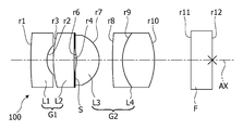
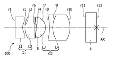
- Fig. 2 is a cross sectional view of an endoscope optical system and optical components located on the downstream side of the endoscope optical system according to the embodiment (example 1) of the invention.
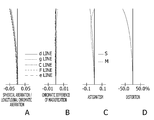
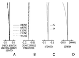
- Figs. 3A to 3D are graphs illustrating the aberrations of the endoscope optical system according to the example 1 of the invention.
- Fig. 4 is a cross sectional view of an endoscope optical system and optical components located on the downstream side of the endoscope optical system according to example 2 of the invention.
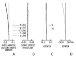
- Figs. 5A to 5D are graphs illustrating the aberrations of the endoscope optical system according to the example 2 of the invention.
- Fig. 1 illustrates an outer appearance of an electronic scope according to an embodiment of the invention.
- Fig. 2 is a cross sectional view of an endoscope optical system and optical components located on the downstream side of the endoscope optical system according to the embodiment (example 1) of the invention
- FIG. 6 is a cross sectional view of an endoscope optical system and optical components located on the downstream side of the endoscope optical system according to example 3 of the invention.
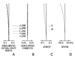
- Figs. 7A to 7D are graphs illustrating the aberrations of the endoscope optical system according to the example 3 of the invention.
- Fig. 8 is a cross sectional view of an endoscope optical system and optical components located on the downstream side of the endoscope optical system according to example 4 of the invention.
- Figs. 9A to 9D are graphs illustrating the aberrations of the endoscope optical system according to the example 4 of the invention.
- Fig. 10 is a cross sectional view of an endoscope optical system and optical components located on the downstream side of the endoscope optical system according to example 5 of the invention.
- FIG. 11A to 11D are graphs illustrating the aberrations of the endoscope optical system according to the example 5 of the invention.
- Fig. 12 is a cross sectional view of an endoscope optical system and optical components located on the downstream side of the endoscope optical system according to example 6 of the invention.
- Figs. 13A to 13D are graphs illustrating the aberrations of the endoscope optical system according to the example 6 of the invention.
- Fig. 14 is a cross sectional view of an endoscope optical system and optical components located on the downstream side of the endoscope optical system according to example 7 of the invention.
- Figs. 15A to 15D are graphs illustrating the aberrations of the endoscope optical system according to the example 7 of the invention.
- FIG. 16 is a cross sectional view of an endoscope optical system and optical components located on the downstream side of the endoscope optical system according to comparative example 1.
- Figs. 17A to 17D are graphs illustrating the aberrations of the endoscope optical system according to the comparative example 1.
- Fig. 18 is a cross sectional view of an endoscope optical system and optical components located on the downstream side of the endoscope optical system according to comparative example 2.
- Figs. 19A to 19D are graphs illustrating the aberrations of the endoscope optical system according to the comparative example 2.
- Fig. 1 illustrates an outer appearance of an electronic scope 1 according to the embodiment.
- the electronic scope 1 has a flexible insertion tube 11 (hereafter, simply referred to as a flexible tube 11) covered from the outside by a flexible sheath 11a.
- a tip part 12 which is covered from the outside by a resin housing having rigidity is connected.
- a bending part 14 provided at a connecting portion between the flexible sheath 11 and the tip part 12 is configured to be able to bend freely through remote manipulation (specifically, rotational operation for a bending operation knob 13a) from an operation unit 11 connected to a proximal end of the flexible sheath 11.
- This bending mechanism has a general configuration installed in a general electronic scope, and is configured to bend the bending part 14 by pulling an operation wire which moves in conjunction with the rotational operation for the bending operation knob 13a. By changing the direction of the tip part 12 in response to the bending movement by the above described operation, an imaging area of the electronic scope 1 moves.
- an endoscope optical system 100 (indicated in a box shape in Fig. 1) is installed.
- the endoscope optical system 100 causes reflected light from the subject to converge onto a photo acceptance surface of a solid state image pick-up device (not shown).
- a solid state image pick-up device a CCD (Charge Coupled Device) image sensor or a CMOS (Complementary Metal Oxide Semiconductor) image sensor can be cited, for example.
- the electronic scope 1 according to the embodiment is designed to be targeted for observation of, for example, a lower digestive organ. Therefore, if the view angle of the endoscope optical system 100 is narrow, there is a concern that an affected area is overlooked. For this reason, the endoscope optical system 100 according to the embodiment is configured on the assumption that the view angle larger than that of a general digital still camera (e.g., the view angle larger than or equal to 120 degrees) is employed.
- a general digital still camera e.g., the view angle larger than or equal to 120 degrees
- Fig. 2 is a cross sectional view of the endoscope optical system 100 according to example 1 (which is described in detail later) and optical components located on the downstream side of the endoscope optical system 100.
- the endoscope optical system 100 is explained in detail with reference to Fig. 2.
- endoscope optical system 100 includes at least a front group G1 and a rear group G2 arranged in this order for from the object (subject) side. More specifically, an optical lens group arranged on the object side with respect to an aperture stop S constitutes the front group G1, and an optical lens group arranged on the image side with respect to the aperture stop S constitutes the rear group G2. Each optical lens constituting the front and rear groups G1 and G2 is configured to be rotationally symmetric with respect to an optical axis AX of the endoscope optical system 100.
- a filter unit F which covers the entire surface of the photo acceptance surface of the solid state image pick-up device is arranged on the rear side of the rear group G2.
- the filer unit F includes a plurality of layers, such as a color correction filter and a cover glass. In this specification and drawings, the filer unit F is illustrated as a single layer for the sake of simplicity.
- the expression like “includes at least " is used in the foregoing because, in another configuration example, the endoscope optical system may include another optical component within the scope of the technical concept of the invention.
- a configuration where a flat plate not substantially contributing to the optical performance of the endoscope optical system is added to the endoscope optical system according to the invention or a configuration where an optical element is added to the endoscope optical system while maintaining the principal configuration and the advantages of the endoscope optical system according to the invention can be considered.
- the expression like “includes at least " is used for explanation of the first group G1 and the second group G2.
- the front group G1 is a lens group having a negative power, and includes at least a negative lens L1 and a positive lens L2 arranged in this order from the object side.
- the rear group G2 is a lens group having a positive power, and includes at least a positive lens L3 and a cemented lens L4 arranged in this order from the object side.
- the cemented lens L4 is formed by cementing together positive and negative lenses.
- the aperture stop S may be a plate-like member having a predetermined circular aperture centering on the optical axis AX, or a light-shielding film coated on a portion other than a predetermined circular area centering on the optical axis AX on a lens surface nearest to the aperture stop S in the front group G1 (i.e., a second surface r4 of the positive lens L2 in the configuration of Fig. 2).
- the thickness of the aperture stop S is considerably small in comparison with the thickness of each of the optical lenses constituting the endoscope optical system 100, and can be neglected in regard to calculation of the optical performance of the endoscope optical system 100. Therefore, in this specification, the explanation is made assuming that the thickness of the aperture stop S is zero.
- the endoscope optical system 100 is configured to satisfy conditions: -10 ⁇ EX/f ⁇ -6 (1), and 1.15 ⁇ f 2 /f ⁇ 1.35 (2).
- the image plane corresponds to the light acceptance surface of the solid state image pick-up device, and is positioned substantially at the same position as the position of a second surface r12 of the filer unit F.
- the exit pupil distance EX extends to the object side with respect to the image plane, and takes a negative sign.
- the incident angle of light with respect to the light acceptance surface of the solid state image pick-up device becomes large, and therefore the shortage of the peripheral light amount by shading becomes large.
- an image pick-up device having a large number of pixels, such as a megapixel has a small pixel size and a low degree of light acceptance efficiency (it should be noted that since the image pick-up device is installed in a tip part of a thin endoscope, the size of the image pick-up device is limited and therefore the size of each pixel is small), the effect of suppressing the shading by a micro lens array is small and the shortage of the peripheral light amount is large.
- the solid state image pick-up device is a fine chip, in this embodiment it is assumed that the position of the photo acceptance surface of the solid state image pick-up device is substantially the same as the position of the micro lens array in the optical axis direction.
- the intermediate term of the condition (1) gets smaller than the lower limit of the condition (1), it becomes necessary to increase the lens diameter of the cemented lens L4 so as to secure the required optical performance of the electronic scope 1 having the wide field angle (e.g., the field angle larger than or equal to 120 degrees) for observing a fine structure in a body cavity. In this case, it becomes difficult to install the endoscope optical system in the tip part 12 having a small diameter.
- the wide field angle e.g., the field angle larger than or equal to 120 degrees
- the front side focal position of the rear group is located on the object side with respect to an aperture stop. Therefore, when the power of the rear group becomes weak (i.e., when the focal length becomes long), the positive magnification becomes small, and the exit pupil distance becomes short.
- the intermediate term of the condition (2) gets larger than the upper limit of the condition (2), the exit pupil distance EX becomes short because the power of the rear group G2 is small and the positive magnification is small, and in this case the shortage of the peripheral light amount by shading becomes large.
- the intermediate term of the condition (2) gets smaller than the lower limit of the condition (2), it becomes necessary to increase the lens diameter of the cemented lens L4 to secure the required optical performance for observation of a body cavity. Since the curvature of field (in particular, the curvature of the meridional image plane) is caused largely in accordance with increase of the diameter of the cemented lens L4, it is difficult to correct the astigmatism for the entire image height.
- the endoscope optical system 100 having the wide filed angle such that the endoscope optical system 100 has the size suitable for installation in the tip part 12 having the small diameter while securing the optical performance required for observation for a fine structure of a body cavity.
- the incident angle of light with respect to an imaging plane can be suppressed by securing the exit pupil distance EX, the shortage of the peripheral light amount by shading is small even when the image is formed on the image pick-up device having a large number of pixels, such as a megapixel.
- the diameter of the endoscope optical system 100 can be decreased.
- the endoscope optical system 100 is configured to satisfy a condition: 2 ⁇ f c /f 2 ⁇ 3.2 (3) where f c (unit: mm) denotes a focal length of the cemented lens L4.
- the cemented lens L4 having the size fitted in the tip part 12 i.e., the tip part 12 having a small size
- the power of the cemented lens L4 is too strong, deterioration of the aberration (in particular, occurrence of the astigmatism caused by the curvature of the meridional image plane) by an installation error (i.e., decentering) is large.
- the endoscope optical system 100 is configured to satisfy a condition: -2.5 ⁇ f 1 /f ⁇ -1.2 (4) where f 1 (unit: mm) denotes the focal length of the front group G1.
- the intermediate term of the condition (4) gets larger than the upper limit of the condition (4), the negative power of the front group G1 is too strong, and therefore it becomes difficult to suitably correct the aberrations including a coma and the chromatic aberration when a designer tries to design the endoscope optical system to have a wide filed angle required for observation of a body cavity. Furthermore, since in this case it is necessary to set the magnification of the rear group G2 to be high, it becomes difficult to suppress change of the magnification of the rear group G2 due to an error of an interval between the front and rear groups G1 and G2 during assembling. Furthermore, since the change of the filed angle due to change of the magnification of the rear group G2 becomes also large, it becomes difficult to assure the stable field angle which satisfies the requirements.
- the intermediate term of the condition (4) gets smaller than the lower limit of the condition (4), it becomes difficult to design the endoscope optical system 100 to suppress the outer diameter of each optical lens, and therefore the endoscope optical system 100 becomes unsuitable for installation in the tip part 12 having a small diameter. Furthermore, since in this case it is necessary to set the magnification of the front group G1 to be high, inclination of the image plane defined when the front group G1 is installed in a state where the front group G1 is decenterred with respect to the optical axis AX becomes large, and deterioration of image quality becomes easy to occur in the peripheral part of the observation field.
- the inclination of the image plane means a phenomenon where the curvature of field ideally remaining symmetrically with respect to the optical axis remains asymmetrically with respect to the optical axis depending on the decentering amount and the decentering direction of an imaging lens caused during assembling.
- the endoscope optical system 100 is configured to satisfy a condition (5) or a condition (6): -0.5 ⁇ R 10 /
- ⁇ 0 (5)
- R 8 (unit: mm) denotes a radius of curvature of the first surface r8 of the cemented lens L4
- R 10 (unit: mm) denotes a radius of curvature of the second surface r10 of the cemented lens L4.
- the second surface r10 located nearest to the image sided in the rear group G2 becomes a concave surface and the exit pupil distance EX becomes short, and therefore the shortage of the peripheral light amount by shading becomes large.
- the exit pupil distance EX becomes short because the power of the cemented lens L4 is weak and the positive magnification is small, and therefore the shortage of the peripheral light amount by shading becomes large.
- the endoscope optical system 100 is configured to simultaneously satisfy the following conditions: 1.3 ⁇ f 21 /f ⁇ 1.8 (7), and -1 ⁇ f/R 6 ⁇ -0.3 (8)
- the power of the positive lens L3 is weak and the coma increases.
- the radius of curvature of the first surface r6 decreases extremely in place of a second surface r7 (a convex surface) of the positive lens L3 whose radius of curvature cannot be set to be large.
- the coma increases.
- the power of the cemented lens L4 needs to be set to be large. In this case, there is a concern with respect to deterioration of the aberration performance due to an assembling decentering error (in particular, occurrence of astigmatism due to curvature of the meridional image plane).
- the intermediate term of the condition (7) gets smaller than the lower limit of the condition (7), it becomes impossible to obtain the suitable aberration performance because the power of the positive lens L3 is too strong. Specifically, the spherical aberration largely occurs in accordance with increase of the power of the positive lens L3, and the curvature of field occurs largely due to increase of Petzval sum, and the astigmatism due to an assembling decentering error increases.
- the power of the positive lens L3 is weak and the coma increases because the radius of curvature of the first surface r6 (a concave surface) of the positive lens L3 is small.
- examples 1 to 7 seven concrete numeric examples (examples 1 to 7) of the endoscope optical system 100 and two comparative examples (comparative examples 1 and 2) to be compared with the examples 1 to 7 are explained.
- the endoscope optical system of each of the examples 1 to 7 and the comparative examples 1 and 2 is arranged in the tip part 12 of the electronic scope 1 shown in Fig. 1.
- the endoscope 100 according to the example 1 has the configuration shown in Fig. 2.
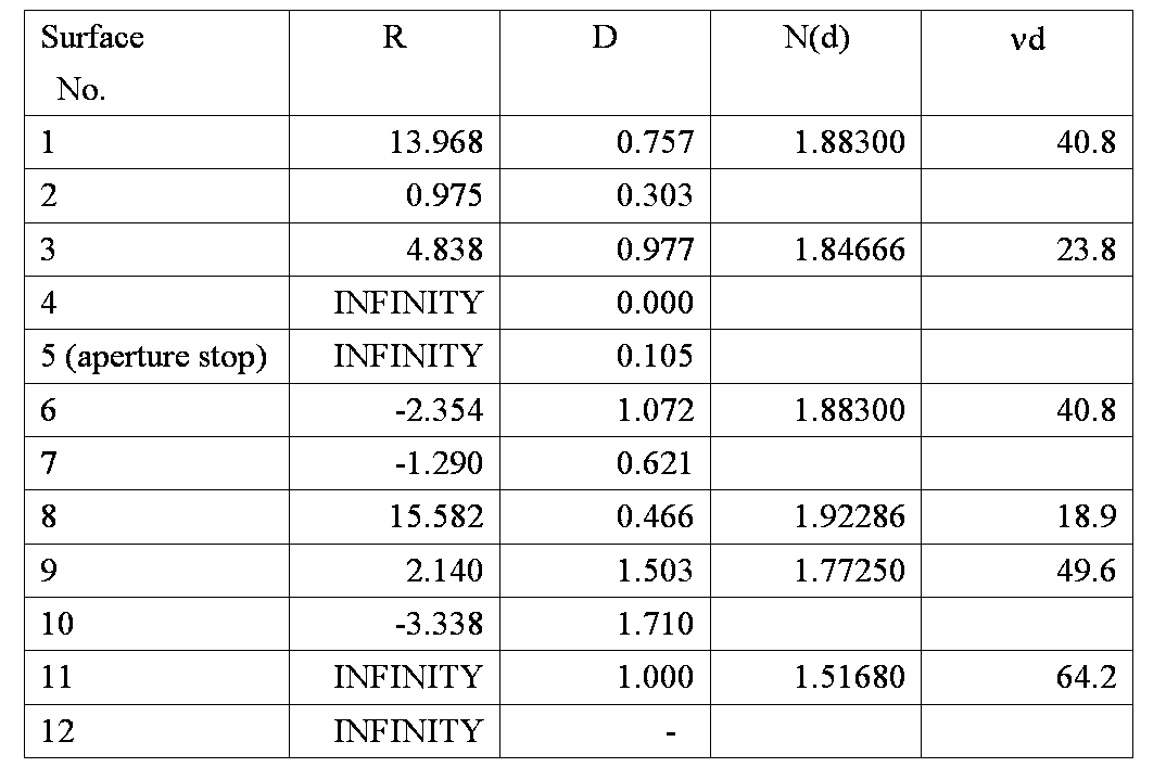
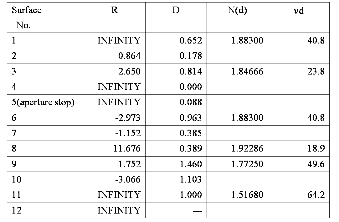
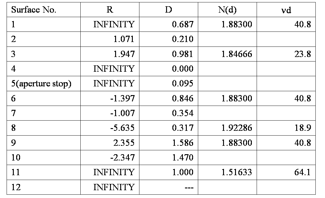
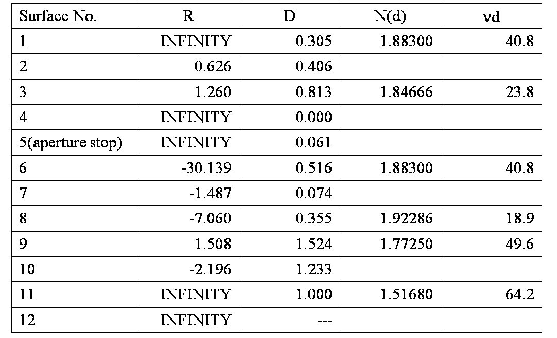
- Table 1 shows the numeric configuration (design values) of the endoscope optical system 100 (and optical components located on the rear side thereof) according to the example 1.
- surface No. corresponds to the reference symbol rn (n: integer) assigned to each surface in Fig. 2, excepting the surface No. 5 of the aperture stop S.
- R unit: mm
- D unit: mm
- N(d) denotes a refractive index at the d-line (wavelength of 588nm)
- nd is Abbe number at the d-line.
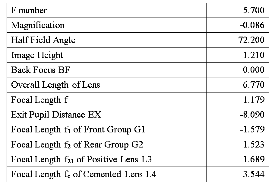
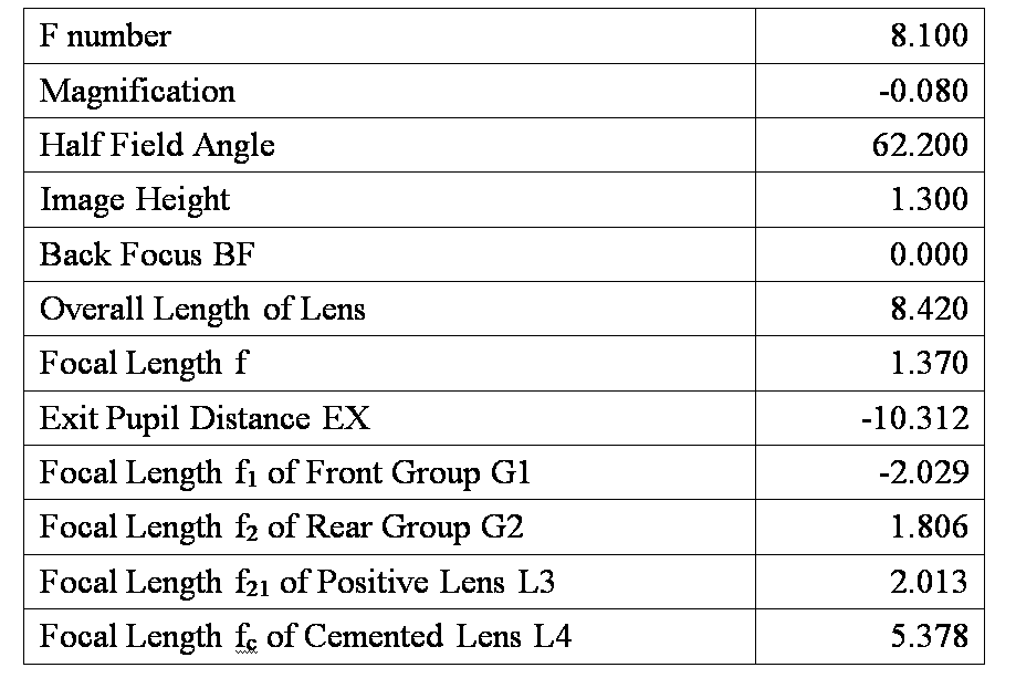
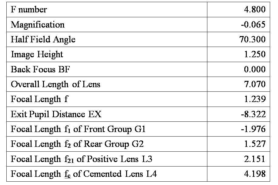
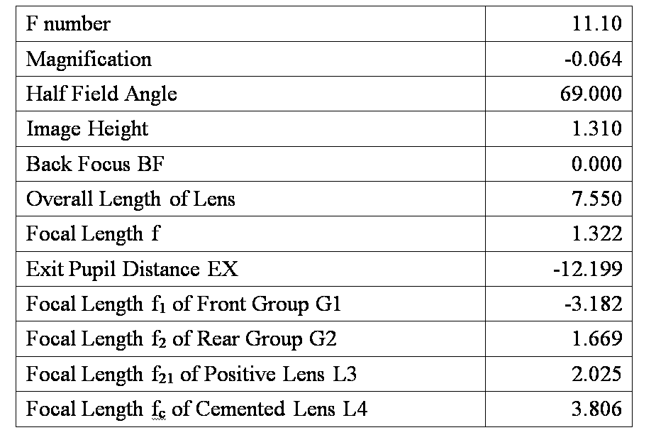
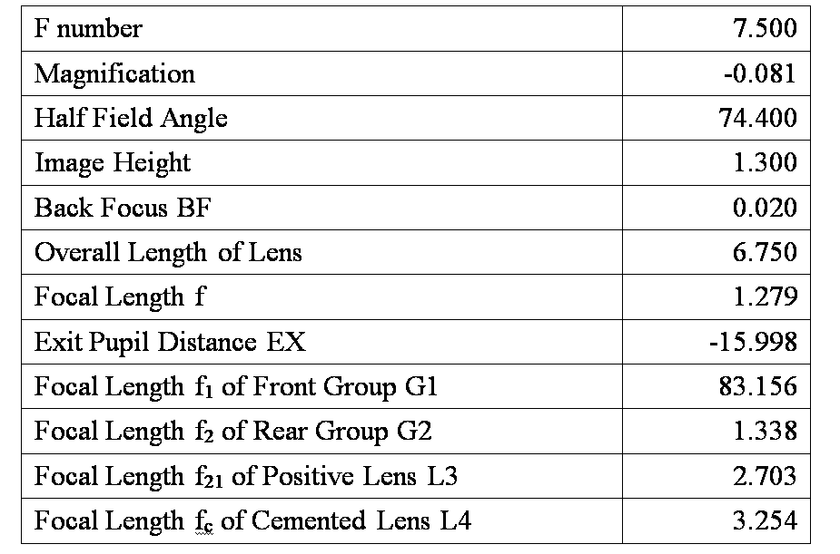
- Table 2 shows the specifications of the endoscope optical system 100.
- the specifications include an effective F number, the optical magnification, the half field angle (unit: degree), the image height (unit: mm), the back focus BF (unit: mm), the overall length (unit: mm) of the endoscope optical system 100, the focal length f (unit: mm) of the entire optical system, the exit pupil distance EX (unit: mm), the focal length f 1 (unit: mm) of the front group G1, the focal length f 2 (unit: mm) of the rear group G2, the focal length f 21 (unit: mm) of the positive lens L3 and the focal length f c (unit: mm) of the cemented lens L4.
- Figs. 3A to 3D are aberration diagrams of the endoscope optical system 100 according to the example 1.
- Fig. 3A is a graph illustrating the spherical aberration and the longitudinal chromatic aberration at each of d-line (588nm), g-line (436 nm), C-line (656nm), F-line (486nm) and e-line (546nm).
- Fig. 3B is a graph illustrating the chromatic difference of magnification at each of d-line, g-line, C-line, F-line and e-line. In each of Figs.
- a curve indicated by a solid line represents the aberration at d-line
- a curve indicated by a dotted line represents the aberration at g-line
- a curve indicated by a chain line represents the aberration at C-line
- a curve indicated by a short dashed line represents the aberration at F-line
- a curve indicated by a long dashed line represents the aberration at e-line.
- Fig. 3C shows the astigmatism.
- a curve indicated by a solid line represents a sagittal component and a curve indicated by a dotted line represents a meridional component.
- Fig. 3D shows the distortion. In each of Figs.
- the vertical axis represents the image height
- the horizontal axis represents the aberration amount
- the vertical axis represents the image height
- the horizontal axis represents the distortion.
- Fig. 4 is a cross sectional view illustrating the arrangement of the optical components including the endoscope optical system 100 according to the example 2.
- the endoscope optical system 100 according to the example 2 has the same number of optical components as that of the endoscope optical system 100 according to the example 1.
- Figs. 5A to 5D are aberration diagrams (the spherical aberration, the longitudinal chromatic aberration, the chromatic difference of magnification, the astigmatism and the distortion) of the endoscope optical system 100 according to the example 2.
- Table 3 shows the numeric configuration of the optical components including the endoscope optical system 100 according to the example 2.
- Table 4 shows the specifications of the endoscope optical system 100 according to the example 2.
- Fig. 6 is a cross sectional view illustrating the arrangement of the optical components including the endoscope optical system 100 according to the example 3.
- the endoscope optical system 100 according to the example 3 has the same number of optical components as that of the endoscope optical system 100 according to the example 1.
- Figs. 7A to 7D are aberration diagrams (the spherical aberration, the longitudinal chromatic aberration, the chromatic difference of magnification, the astigmatism and the distortion) of the endoscope optical system 100 according to the example 3.
- Table 5 shows the numeric configuration of the optical components including the endoscope optical system 100 according to the example 3.
- Table 6 shows the specifications of the endoscope optical system 100 according to the example 3.
- Fig. 8 is a cross sectional view illustrating the arrangement of the optical components including the endoscope optical system 100 according to the example 4.
- the endoscope optical system 100 according to the example 4 has the same number of optical components as that of the endoscope optical system 100 according to the example 1.
- Figs. 9A to 9D are aberration diagrams (the spherical aberration, the longitudinal chromatic aberration, the chromatic difference of magnification, the astigmatism and the distortion) of the endoscope optical system 100 according to the example 4.
- Table 7 shows the numeric configuration of the optical components including the endoscope optical system 100 according to the example 4.
- Table 8 shows the specifications of the endoscope optical system 100 according to the example 4.
- Fig. 10 is a cross sectional view illustrating the arrangement of the optical components including the endoscope optical system 100 according to the example 5.
- the endoscope optical system 100 according to the example 5 has the same number of optical components as that of the endoscope optical system 100 according to the example 1.
- Figs. 11A to 11D are aberration diagrams (the spherical aberration, the longitudinal chromatic aberration, the chromatic difference of magnification, the astigmatism and the distortion) of the endoscope optical system 100 according to the example 5.
- Table 9 shows the numeric configuration of the optical components including the endoscope optical system 100 according to the example 5.
- Table 10 shows the specifications of the endoscope optical system 100 according to the example 5.
- Fig. 12 is a cross sectional view illustrating the arrangement of the optical components including the endoscope optical system 100 according to the example 6.
- the endoscope optical system 100 according to the example 6 has the same number of optical components as that of the endoscope optical system 100 according to the example 1.
- Figs. 13A to 13D are aberration diagrams (the spherical aberration, the longitudinal chromatic aberration, the chromatic difference of magnification, the astigmatism and the distortion) of the endoscope optical system 100 according to the example 6.
- Table 11 shows the numeric configuration of the optical components including the endoscope optical system 100 according to the example 6.
- Table 12 shows the specifications of the endoscope optical system 100 according to the example 6.
- Fig. 14 is a cross sectional view illustrating the arrangement of the optical components including the endoscope optical system 100 according to the example 7.
- the endoscope optical system 100 according to the example 7 has the same number of optical components as that of the endoscope optical system 100 according to the example 1.
- Figs. 15A to 15D are aberration diagrams (the spherical aberration, the longitudinal chromatic aberration, the chromatic difference of magnification, the astigmatism and the distortion) of the endoscope optical system 100 according to the example 7.
- Table 13 shows the numeric configuration of the optical components including the endoscope optical system 100 according to the example 7.
- Table 14 shows the specifications of the endoscope optical system 100 according to the example 7.
- Fig. 16 is a cross sectional view illustrating the arrangement of the optical components including an endoscope optical system 100C according to the comparative example 1.
- the endoscope optical system 100C according to the comparative example 1 has the same number of optical components as that of the endoscope optical system 100 according to the example 1.
- Figs. 17A to 17D are aberration diagrams (the spherical aberration, the longitudinal chromatic aberration, the chromatic difference of magnification, the astigmatism and the distortion) of the endoscope optical system 100C according to the comparative example 1.
- Table 15 shows the numeric configuration of the optical components including the endoscope optical system 100C according to the comparative example 1.
- Table 16 shows the specifications of the endoscope optical system 100C according to the comparative example 1.
- Fig. 18 is a cross sectional view illustrating the arrangement of the optical components including the endoscope optical system 100C according to the comparative example 2.
- the endoscope optical system 100C according to the comparative example 2 has the same number of optical components as that of the endoscope optical system 100 according to the example 1.
- Figs. 19A to 19D are aberration diagrams (the spherical aberration, the longitudinal chromatic aberration, the chromatic difference of magnification, the astigmatism and the distortion) of the endoscope optical system 100C according to the comparative example 2.
- Table 17 shows the numeric configuration of the optical components including the endoscope optical system 100C according to the comparative example 2.
- Table 18 shows the specifications of the endoscope optical system 100C according to the comparative example 2.
- Table 19 shows values of the conditions (1) to (8) for each of the above described examples 1 to 7 and the comparative examples 1 and 2.
- the endoscope optical system 100C according to each of the comparative examples 1 and 2 does not satisfy the conditions (1) and (2). Since the lens diameter of the cemented lens L4 of the endoscope optical system 100C according to the comparative example 1 is large as shown in Fig. 16 or 17, the endoscope optical system 100C according to the comparative example 1 is not suitable for installation in the tip part 12, and causes a large amount of astigmatism due to the curvature of field (in particular, the curvature of the meridional image plane).
- the endoscope optical system 100 according to each of the examples 1 to 7 satisfies the conditions (1) and (2) simultaneously as shown in Table 19. Therefore, the endoscope optical system 100 according to each of the examples 1 to 7 can be configured to reduce the size to be suitable for installation in the tip part 12 having the small outer diameter while securing the optical performance required for observation of a fine structure in a body cavity.
- the incident angle of light with respect to the image plane can be suppressed by securing the exit pupil distance EX, the shortage of the peripheral light amount due to shading is small even when the image is formed on the image pick-up device having a large number of pixels, such as a megapixel.
- the endoscope optical system 100 according to each of the examples 1 to 7 further satisfies the conditions (3) to (8). Therefore, the endoscope optical system 100 according to each of the examples 1 to 7 is also able to achieve the advantages which are described above in relation to the conditions (3) to (8), in addition to the advantages brought by satisfying the conditions (1) and (2).
Landscapes
- Physics & Mathematics (AREA)
- Optics & Photonics (AREA)
- General Physics & Mathematics (AREA)
- Health & Medical Sciences (AREA)
- Life Sciences & Earth Sciences (AREA)
- Astronomy & Astrophysics (AREA)
- Surgery (AREA)
- Engineering & Computer Science (AREA)
- Molecular Biology (AREA)
- Pathology (AREA)
- Nuclear Medicine, Radiotherapy & Molecular Imaging (AREA)
- Biomedical Technology (AREA)
- Heart & Thoracic Surgery (AREA)
- Medical Informatics (AREA)
- Radiology & Medical Imaging (AREA)
- Animal Behavior & Ethology (AREA)
- General Health & Medical Sciences (AREA)
- Public Health (AREA)
- Veterinary Medicine (AREA)
- Biophysics (AREA)
- Lenses (AREA)
- Endoscopes (AREA)
- Instruments For Viewing The Inside Of Hollow Bodies (AREA)
Abstract
Description
-10 < EX/f < -6 (1), and
1.15 < f2/f < 1.35 (2).
2 < fc/f2 < 3.2 (3).
-2.5 < f1/f < -1.2 (4).
-0.5 < R10/|R8| <= 0 (5)
|R8|/R10 < -2 (6)
1.3 < f21/f < 1.8 (7), and
-1 < f/R6 < -0.3 (8).
-10 < EX/f < -6 (1), and
1.15 < f2/f < 1.35 (2).
2 < fc/f2 < 3.2 (3)
where fc (unit: mm) denotes a focal length of the cemented lens L4.
-2.5 < f1/f < -1.2 (4)
where f1 (unit: mm) denotes the focal length of the front group G1.
-0.5 < R10/|R8| <= 0 (5)
|R8|/R10 < -2 (6)
where R8 (unit: mm) denotes a radius of curvature of the first surface r8 of the cemented lens L4 and R10 (unit: mm) denotes a radius of curvature of the second surface r10 of the cemented lens L4.
1.3 < f21/f < 1.8 (7), and
-1 < f/R6 < -0.3 (8)








Claims (7)
- An endoscope optical system, comprising:
a front group; and
a rear group,
the front group and the rear group being arranged in this order from an object side such that an aperture stop is arranged between the front group and the rear group,
wherein:
the front group comprises a negative lens and a positive lens arranged in this order from the object side;
the rear group comprises a positive lens and a cemented lens arranged in this order from the object side; and
when f (unit: mm) denotes a focal length of an entire endoscope optical system, EX (unit: mm) denotes a distance (which takes a minus sign on the object side with respect to an image plane) from the image plane to an exit pupil, and f2 (unit: mm) denotes a focal length of the rear group, the endoscope optical system satisfies conditions:
-10 < EX/f < -6 (1), and
1.15 < f2/f < 1.35 (2). - The endoscope optical system according to claim 1,
wherein when fc (unit: mm) denotes a focal length of the cemented lens, the endoscope optical systems satisfies a condition:
2 < fc/f2 < 3.2 (3). - The endoscope optical system according to claim 1 or 2,
wherein when f1 (unit: mm) denotes a focal length of the front group, the endoscope optical system satisfies a condition:
-2.5 < f1/f < -1.2 (4). - The endoscope optical system according to any of claims 1 to 3,
wherein when R8 (unit: mm) denotes a radius of curvature of an object side surface of the cemented lens and R10 (unit: mm) denotes a radius of curvature of an image side surface of the cemented lens, the endoscope optical system satisfies a condition:
-0.5 < R10/|R8| <= 0 (5). - The endoscope optical system according to any of claims 1 to 3,
wherein when R8 (unit: mm) denotes a radius of curvature of an object side surface of the cemented lens and R10 (unit: mm) denotes a radius of curvature of an image side surface of the cemented lens, the endoscope optical system satisfies a condition:
|R8|/R10 < -2 (6). - The endoscope optical system according to any of claims 1 to 5,
wherein:
the positive lens of the rear group is a positive meniscus lens having a concave surface facing the object side; and
when f21 (unit: mm) denotes a focal length of the positive lens of the rear group, and R6 (unit: mm) denotes a radius of curvature of an object side surface of the positive lens of the rear group, the endoscope optical system satisfies conditions:
1.3 < f21/f < 1.8 (7), and
-1 < f/R6 < -0.3 (8). - An endoscope, comprising:
a flexible insertion tube having an endoscope optical system according to any of claims 1 to 6 provided at a tip part of the flexible insertion tube.
Priority Applications (3)
| Application Number | Priority Date | Filing Date | Title |
|---|---|---|---|
| CN201280008221.2A CN103370646B (en) | 2011-02-10 | 2012-02-07 | endoscope optical system and endoscope |
| DE112012000763.8T DE112012000763B4 (en) | 2011-02-10 | 2012-02-07 | Endoscope optics and endoscope |
| US13/984,169 US8767320B2 (en) | 2011-02-10 | 2012-02-07 | Endoscope optical system and endoscope |
Applications Claiming Priority (2)
| Application Number | Priority Date | Filing Date | Title |
|---|---|---|---|
| JP2011027091A JP5653243B2 (en) | 2011-02-10 | 2011-02-10 | Endoscope optical system and endoscope |
| JP2011-027091 | 2011-02-10 |
Publications (1)
| Publication Number | Publication Date |
|---|---|
| WO2012108177A1 true WO2012108177A1 (en) | 2012-08-16 |
Family
ID=46638398
Family Applications (1)
| Application Number | Title | Priority Date | Filing Date |
|---|---|---|---|
| PCT/JP2012/000795 Ceased WO2012108177A1 (en) | 2011-02-10 | 2012-02-07 | Endoscope optical system and endoscope |
Country Status (5)
| Country | Link |
|---|---|
| US (1) | US8767320B2 (en) |
| JP (1) | JP5653243B2 (en) |
| CN (1) | CN103370646B (en) |
| DE (1) | DE112012000763B4 (en) |
| WO (1) | WO2012108177A1 (en) |
Cited By (3)
| Publication number | Priority date | Publication date | Assignee | Title |
|---|---|---|---|---|
| CN107656359A (en) * | 2016-07-26 | 2018-02-02 | 豪威科技股份有限公司 | Five surface wide visual field compound lenses and associated camera model |
| US10437039B2 (en) | 2013-10-30 | 2019-10-08 | Olympus Corporation | Image-acquisition apparatus |
| US11487101B2 (en) * | 2017-09-12 | 2022-11-01 | Hoya Corporation | Endoscope objective lens unit and endoscope |
Families Citing this family (10)
| Publication number | Priority date | Publication date | Assignee | Title |
|---|---|---|---|---|
| WO2012176667A1 (en) * | 2011-06-23 | 2012-12-27 | オリンパスメディカルシステムズ株式会社 | Endoscope objective optical system |
| JP2015060019A (en) * | 2013-09-18 | 2015-03-30 | 富士フイルム株式会社 | Endoscope objective lens and endoscope |
| JP6150717B2 (en) * | 2013-12-05 | 2017-06-21 | オリンパス株式会社 | Stereo imaging optical system, stereo imaging device, and endoscope |
| JP6579789B2 (en) * | 2014-06-10 | 2019-09-25 | キヤノン株式会社 | Zoom lens and imaging apparatus having the same |
| DE112016000121B4 (en) * | 2015-09-07 | 2019-07-04 | Hoya Corporation | Endoscope magnifying optics and endoscope |
| CN105662315A (en) * | 2015-12-31 | 2016-06-15 | 天津市融和机电科技有限公司 | High-resolution breast duct endoscope optical system |
| US10498940B2 (en) * | 2016-04-29 | 2019-12-03 | Deuk Soo Jang | Endoscope |
| JP2019049680A (en) * | 2017-09-12 | 2019-03-28 | Hoya株式会社 | Objective lens unit for endoscope and endoscope |
| JP7285643B2 (en) * | 2018-12-27 | 2023-06-02 | 株式会社タムロン | Optical system and imaging device |
| JP7285091B2 (en) | 2019-02-27 | 2023-06-01 | 株式会社タムロン | Imaging optical system and imaging device |
Citations (3)
| Publication number | Priority date | Publication date | Assignee | Title |
|---|---|---|---|---|
| JPH08122632A (en) * | 1994-10-18 | 1996-05-17 | Fuji Photo Optical Co Ltd | Objective for endoscope |
| JP2007249189A (en) * | 2006-02-14 | 2007-09-27 | Fujinon Corp | Endoscope objective lens |
| JP2009080413A (en) * | 2007-09-27 | 2009-04-16 | Fujinon Corp | Imaging optical system, image pickup apparatus for endoscope |
Family Cites Families (13)
| Publication number | Priority date | Publication date | Assignee | Title |
|---|---|---|---|---|
| JP2596827B2 (en) * | 1989-05-09 | 1997-04-02 | オリンパス光学工業株式会社 | Endoscope objective lens |
| US5175650A (en) | 1989-05-09 | 1992-12-29 | Olympus Optical Co., Ltd. | Objective lens system for endoscopes |
| JP3359092B2 (en) | 1993-04-23 | 2002-12-24 | オリンパス光学工業株式会社 | Endoscope objective lens |
| JP2000330015A (en) * | 1999-03-12 | 2000-11-30 | Fuji Photo Optical Co Ltd | Variable observation depth objective lens for endoscopes |
| JP4236241B2 (en) * | 2002-07-26 | 2009-03-11 | フジノン株式会社 | Endoscope objective lens |
| JP4150565B2 (en) * | 2002-09-25 | 2008-09-17 | Hoya株式会社 | Endoscope objective lens system |
| JP4245985B2 (en) | 2003-05-30 | 2009-04-02 | オリンパス株式会社 | Endoscope objective lens |
| CN100464207C (en) * | 2007-04-11 | 2009-02-25 | 王华林 | Upper digestive tract electronic endoscope objective lens |
| JP4695662B2 (en) * | 2008-03-18 | 2011-06-08 | オリンパスメディカルシステムズ株式会社 | Endoscope objective lens |
| CN101630058B (en) * | 2008-07-18 | 2011-03-23 | 上海澳华光电内窥镜有限公司 | Objective lens of endoscope |
| JP5324321B2 (en) * | 2009-05-29 | 2013-10-23 | 富士フイルム株式会社 | Endoscope objective lens and endoscope |
| JP5031930B2 (en) * | 2009-12-24 | 2012-09-26 | オリンパスメディカルシステムズ株式会社 | Endoscope objective lens and endoscope using the same |
| JP4902033B1 (en) * | 2010-04-07 | 2012-03-21 | オリンパスメディカルシステムズ株式会社 | Objective lens and endoscope using the same |
-
2011
- 2011-02-10 JP JP2011027091A patent/JP5653243B2/en active Active
-
2012
- 2012-02-07 DE DE112012000763.8T patent/DE112012000763B4/en active Active
- 2012-02-07 CN CN201280008221.2A patent/CN103370646B/en active Active
- 2012-02-07 WO PCT/JP2012/000795 patent/WO2012108177A1/en not_active Ceased
- 2012-02-07 US US13/984,169 patent/US8767320B2/en active Active
Patent Citations (3)
| Publication number | Priority date | Publication date | Assignee | Title |
|---|---|---|---|---|
| JPH08122632A (en) * | 1994-10-18 | 1996-05-17 | Fuji Photo Optical Co Ltd | Objective for endoscope |
| JP2007249189A (en) * | 2006-02-14 | 2007-09-27 | Fujinon Corp | Endoscope objective lens |
| JP2009080413A (en) * | 2007-09-27 | 2009-04-16 | Fujinon Corp | Imaging optical system, image pickup apparatus for endoscope |
Cited By (3)
| Publication number | Priority date | Publication date | Assignee | Title |
|---|---|---|---|---|
| US10437039B2 (en) | 2013-10-30 | 2019-10-08 | Olympus Corporation | Image-acquisition apparatus |
| CN107656359A (en) * | 2016-07-26 | 2018-02-02 | 豪威科技股份有限公司 | Five surface wide visual field compound lenses and associated camera model |
| US11487101B2 (en) * | 2017-09-12 | 2022-11-01 | Hoya Corporation | Endoscope objective lens unit and endoscope |
Also Published As
| Publication number | Publication date |
|---|---|
| US20130317299A1 (en) | 2013-11-28 |
| JP2012168245A (en) | 2012-09-06 |
| CN103370646A (en) | 2013-10-23 |
| CN103370646B (en) | 2016-01-20 |
| JP5653243B2 (en) | 2015-01-14 |
| US8767320B2 (en) | 2014-07-01 |
| DE112012000763B4 (en) | 2017-01-19 |
| DE112012000763T5 (en) | 2013-11-28 |
Similar Documents
| Publication | Publication Date | Title |
|---|---|---|
| US8767320B2 (en) | Endoscope optical system and endoscope | |
| JP5651861B2 (en) | Imaging lens | |
| JP6029111B2 (en) | Imaging lens | |
| JP5601924B2 (en) | Endoscope variable magnification optical system and endoscope | |
| WO2017145265A1 (en) | Variable magnification optical system for endoscope and endscope | |
| JP5587513B2 (en) | Objective optical system and endoscope apparatus using the same | |
| CN107111112B (en) | Objective optical system for endoscope | |
| JP2017068164A (en) | Wide-angle optical system and imaging apparatus including the same | |
| CN106716214A (en) | Variable power optical system for endoscope, and endoscope | |
| JP7559045B2 (en) | Wide-field objective lens | |
| JP2007206516A (en) | Imaging lens | |
| JP4981466B2 (en) | Optical system and imaging apparatus having the same | |
| JP5031880B2 (en) | Endoscope objective lens | |
| JP6337687B2 (en) | Rear conversion lens | |
| JP6754916B2 (en) | Variable magnification optics for endoscopes and endoscopes | |
| JP4150565B2 (en) | Endoscope objective lens system | |
| JP5082486B2 (en) | Zoom lens and optical apparatus having the same | |
| CN112748556B (en) | An endoscope optical system | |
| JP2008191231A (en) | Optical system and imaging apparatus having the same | |
| CN107703606B (en) | Objective optical system for endoscope and endoscope | |
| JP5308915B2 (en) | Imaging lens | |
| JP3038974B2 (en) | Small wide-angle lens | |
| JP5006627B2 (en) | Optical system and optical apparatus having the same | |
| JP2009288776A (en) | Imaging lens | |
| JP5187951B2 (en) | Imaging lens |
Legal Events
| Date | Code | Title | Description |
|---|---|---|---|
| WWE | Wipo information: entry into national phase |
Ref document number: 201280008221.2 Country of ref document: CN |
|
| 121 | Ep: the epo has been informed by wipo that ep was designated in this application |
Ref document number: 12745079 Country of ref document: EP Kind code of ref document: A1 |
|
| WWE | Wipo information: entry into national phase |
Ref document number: 13984169 Country of ref document: US |
|
| WWE | Wipo information: entry into national phase |
Ref document number: 112012000763 Country of ref document: DE Ref document number: 1120120007638 Country of ref document: DE |
|
| 122 | Ep: pct application non-entry in european phase |
Ref document number: 12745079 Country of ref document: EP Kind code of ref document: A1 |