WO2012105033A1 - 電池及びその製造方法 - Google Patents
電池及びその製造方法 Download PDFInfo
- Publication number
- WO2012105033A1 WO2012105033A1 PCT/JP2011/052328 JP2011052328W WO2012105033A1 WO 2012105033 A1 WO2012105033 A1 WO 2012105033A1 JP 2011052328 W JP2011052328 W JP 2011052328W WO 2012105033 A1 WO2012105033 A1 WO 2012105033A1
- Authority
- WO
- WIPO (PCT)
- Prior art keywords
- container
- gas
- unit cell
- battery
- positive electrode
- Prior art date
- Legal status (The legal status is an assumption and is not a legal conclusion. Google has not performed a legal analysis and makes no representation as to the accuracy of the status listed.)
- Ceased
Links
Images


Classifications
-
- H—ELECTRICITY
- H01—ELECTRIC ELEMENTS
- H01M—PROCESSES OR MEANS, e.g. BATTERIES, FOR THE DIRECT CONVERSION OF CHEMICAL ENERGY INTO ELECTRICAL ENERGY
- H01M10/00—Secondary cells; Manufacture thereof
- H01M10/04—Construction or manufacture in general
- H01M10/049—Processes for forming or storing electrodes in the battery container
-
- Y—GENERAL TAGGING OF NEW TECHNOLOGICAL DEVELOPMENTS; GENERAL TAGGING OF CROSS-SECTIONAL TECHNOLOGIES SPANNING OVER SEVERAL SECTIONS OF THE IPC; TECHNICAL SUBJECTS COVERED BY FORMER USPC CROSS-REFERENCE ART COLLECTIONS [XRACs] AND DIGESTS
- Y02—TECHNOLOGIES OR APPLICATIONS FOR MITIGATION OR ADAPTATION AGAINST CLIMATE CHANGE
- Y02E—REDUCTION OF GREENHOUSE GAS [GHG] EMISSIONS, RELATED TO ENERGY GENERATION, TRANSMISSION OR DISTRIBUTION
- Y02E60/00—Enabling technologies; Technologies with a potential or indirect contribution to GHG emissions mitigation
- Y02E60/10—Energy storage using batteries
-
- Y—GENERAL TAGGING OF NEW TECHNOLOGICAL DEVELOPMENTS; GENERAL TAGGING OF CROSS-SECTIONAL TECHNOLOGIES SPANNING OVER SEVERAL SECTIONS OF THE IPC; TECHNICAL SUBJECTS COVERED BY FORMER USPC CROSS-REFERENCE ART COLLECTIONS [XRACs] AND DIGESTS
- Y02—TECHNOLOGIES OR APPLICATIONS FOR MITIGATION OR ADAPTATION AGAINST CLIMATE CHANGE
- Y02P—CLIMATE CHANGE MITIGATION TECHNOLOGIES IN THE PRODUCTION OR PROCESSING OF GOODS
- Y02P70/00—Climate change mitigation technologies in the production process for final industrial or consumer products
- Y02P70/50—Manufacturing or production processes characterised by the final manufactured product
Definitions
- the present invention relates to a battery having a unit cell that is pressurized using a gas, and a method for manufacturing the same.
- Lithium ion secondary batteries (hereinafter sometimes referred to as “lithium secondary batteries” or “batteries”) have characteristics that they have higher energy density than other secondary batteries and can operate at high voltages. is doing. For this reason, it is used as a secondary battery that can be easily reduced in size and weight in information equipment such as a mobile phone, and in recent years, there is an increasing demand for large motive power such as for electric vehicles and hybrid vehicles.
- a lithium ion secondary battery includes a positive electrode layer and a negative electrode layer, and an electrolyte layer disposed therebetween.
- the electrolyte included in the electrolyte layer include non-aqueous liquid and solid substances. Used. When a liquid electrolyte (hereinafter referred to as “electrolytic solution”) is used, the electrolytic solution easily penetrates into the positive electrode layer and the negative electrode layer. Therefore, an interface between the active material contained in the positive electrode layer or the negative electrode layer and the electrolytic solution is easily formed, and the performance is easily improved.
- electrolyte since the widely used electrolyte is flammable, it is necessary to mount a system for ensuring safety.
- solid electrolyte since the solid electrolyte (hereinafter referred to as “solid electrolyte”) is nonflammable, the above system can be simplified. Therefore, a lithium ion secondary battery (hereinafter referred to as “solid battery”) in a form provided with a layer containing a solid electrolyte that is nonflammable (hereinafter referred to as “solid electrolyte layer”) has been proposed. Yes.
- Patent Document 1 in an assembled battery in which a plurality of unit cells are combined and housed in an assembled battery case, gas is filled in the space inside the assembled battery case outside the unit cell case.
- a lithium secondary battery that pressurizes the unit cell using the hydrostatic pressure generated in the assembled battery case is disclosed.
- Patent Document 2 in a battery provided with a safety valve for releasing the internal pressure of the battery, the flow passage cross-sectional area of the gas ejection part after the safety valve is activated in response to the temperature of the ejection gas emitted from the battery when the safety valve is activated.
- a battery using a solid material that has a function of expanding the temperature and sublimates at a temperature of 80 ° C. to 130 ° C. for a valve seat and / or a valve body of a gas ejection portion of a safety valve.
- the first current collector is connected to a metal lid of a metal case that houses the first current collector of one polarity and the second current collector of the other polarity
- a battery is disclosed in which a second current collector is connected to a terminal provided through an insulator made of a material having sublimation properties on the lid.
- Patent Document 4 discloses a sodium secondary battery comprising a sodium secondary battery main body and a module main body surrounded by a heat insulating means outside the sodium secondary battery main body, and the heat insulating means is at least two or more in the vertical axis direction. There is disclosed a mode in which a vacuum heat insulating portion formed by dividing the sublimation material into a vacuum heat insulating structure is provided.
- JP-A-10-214638 Japanese Patent Laid-Open No. 11-250884 JP 2005-285555 A JP 2001-229960 A
- the unit cell is pressurized using hydrostatic pressure, and it is considered that local deterioration of the cell can be suppressed.
- the gas for pressurizing the unit cell is filled in the assembled battery case in the state in which the unit cell is pressurized, workability when filling the gas is improved. There was a problem that it was easy to decrease.
- the technique disclosed in Patent Document 1 has a problem that it is difficult to maintain the performance of the battery over a long period of time because no measures are taken to suppress fluctuations in the hydrostatic pressure. It was. These problems have been difficult to solve even if the technique disclosed in Patent Document 1 and the techniques disclosed in Patent Documents 2 to 4 are combined.
- a first aspect of the present invention comprises a unit cell having a positive electrode and a negative electrode, and an electrolyte layer disposed between the positive electrode and the negative electrode, and a container for housing the unit cell, and the container is filled.
- a method of manufacturing a battery in which a unit cell is pressurized using the gas wherein a gas for pressurizing the unit cell and / or a substance that generates the gas is contained in a container, and the gas is And / or a housing and sealing process for sealing the container in which the substance is housed, and a pressure-increasing process for increasing the pressure of the gas that pressurizes the unit cell in the sealed container. It is.
- “accommodating the gas for pressurizing the unit cell into the container” means filling the container with the gas before the pressure is increased in the high pressure process.
- “accommodating the substance that generates the gas in the container” means that a liquid gas such as liquid helium or liquid nitrogen that vaporizes the gas to be pressurized by the unit cell (hereinafter simply “liquefied”). Gas, etc.), a solid that sublimates and generates a gas that should pressurize the unit cell (for example, dry ice or naphthalene), or a substance that generates a gas that pressurizes the unit cell by chemical reaction. It means to be accommodated in a container.
- “accommodating the gas for pressurizing the unit cell and the substance that generates the gas in the container” means, for example, that the gas is liquefied together with the vaporized gas in a temperature environment where the liquefied gas can vaporize.
- a solid that generates a gas that should be sublimated to pressurize the unit cell is contained in the container together with the sublimated gas in a temperature environment where the solid can be sublimated. That means.
- “increasing the pressure of the gas for pressurizing the unit cell” means that the temperature of the container is raised more than the housing and sealing step when the gas for pressurizing the unit cell is stored in the container in the housing and sealing step. Means to increase the pressure of the gas.
- the pressure of the gas that pressurizes the unit cell is increased by generating the gas from the liquefied gas.
- the pressure of the gas for pressurizing the unit cell is increased by generating gas from the solid to be sublimated.
- a substance that generates a gas to pressurize the unit cell by chemical reaction in the container sealing process is contained in the container, a gas that pressurizes the unit cell by causing a chemical reaction in the container. It means to increase the pressure.
- the housing and sealing step is performed under a temperature environment different from that during battery operation.
- the electrolyte layer is preferably a solid electrolyte layer.
- the temperature of the gas that pressurizes the unit cell and / or the substance that generates the gas is preferably different from that during the operation of the battery in the housing and sealing step.
- a second aspect of the present invention includes a unit cell having a positive electrode and a negative electrode, and an electrolyte layer disposed between the positive electrode and the negative electrode, and a container for housing the unit cell, and the container is filled.
- the battery is characterized in that the unit cell is pressurized using the gas, and the gas and the liquid or solid in phase equilibrium with the gas are contained in the container.
- the electrolyte layer is preferably a solid electrolyte layer.
- the battery is manufactured through the housing and sealing step and the high pressure step.
- a gas to be pressurized after filling a container with a gas containing normal pressure ( atmospheric pressure; the same applies hereinafter) or a substance containing a liquid or a solid and then sealing the container.
- the pressure of is increased.
- the substance can be easily put into the container without using high-pressure equipment such as a diaphragm compressor. Can be accommodated. Therefore, by adopting such a form, in addition to the above effects, it becomes easy to reduce the manufacturing cost of the battery.
- the electrolyte layer is a solid electrolyte layer, it becomes easy to enhance the safety of the battery in addition to the above effects.
- the temperature of the gas that pressurizes the unit cell and / or the substance that generates the gas in the housing and sealing step is different from that during the operation of the battery. It becomes easier to reduce the manufacturing cost.
- the gas for pressurizing the unit cell and the liquid or solid in phase equilibrium with the gas are stored in the container for storing the unit cell.
- the battery according to the second aspect of the present invention can be manufactured using the battery manufacturing method according to the first aspect of the present invention. Therefore, according to the 2nd aspect of this invention, the battery which can improve workability
- a gas or a liquid or solid that is in phase equilibrium with the pressurizing unit cell is contained in the container. Therefore, even when gas is generated from the unit cell or a small amount of gas leaks from the container, the pressure of the gas that pressurizes the unit cell is kept constant by moving the equilibrium. Can do. Therefore, according to the second aspect of the present invention, the performance of the battery can be maintained over a long period of time.
- the electrolyte layer is a solid electrolyte layer, it becomes easy to enhance the safety of the battery in addition to the above effects.
- FIG. 2 is a cross-sectional view illustrating a battery 10.
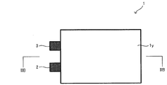
- FIG. 4 is a top view of the unit cell 1, the positive electrode terminal 2, and the negative electrode terminal 3.
- FIG. 1 is a cross-sectional view of a unit cell 1.
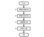
- 3 is a flowchart illustrating a method for manufacturing battery 10.
- the battery manufacturing method of the present invention is a method of manufacturing a lithium ion secondary battery having a solid electrolyte layer
- the battery of the present invention is a lithium ion secondary battery having a solid electrolyte layer.
- the case will be mainly described.
- the form shown below is an illustration of this invention and this invention is not limited to the form shown below.
- FIG. 1 is a cross-sectional view illustrating a battery 10 of the present invention.
- a unit cell 1 which is a solid state battery is shown in a simplified manner.
- the battery 10 includes a unit cell 1, a terminal 2 (positive electrode terminal 2) connected to the unit cell 1, and a container 4 that houses the unit cell 1.
- the unit cell 1 accommodated in the container 4 is filled with nitrogen gas, and the liquid nitrogen 5 is also accommodated in the container 4.
- FIG. 2A is a top view of the unit cell 1, the positive electrode terminal 2, and the negative electrode terminal 3, and FIG. 2B is a cross-sectional view taken along the line IIB-IIB of FIG. 2A.
- the unit cell 1 includes a laminate 1x and a laminate film 1y that wraps the laminate 1x.
- the laminate 1x includes a positive electrode current collector 1a, a positive electrode layer 1b connected to the positive electrode current collector 1a, and a solid electrolyte layer disposed so as to be in contact with the positive electrode layer 1b.
- a positive electrode terminal 2 is connected to the positive electrode current collector 1a, and a negative electrode terminal 3 is connected to the negative electrode current collector 1e.
- the nitrogen gas filling the periphery of the unit cell 1 and the liquid nitrogen 5 are in phase equilibrium, and the unit cell 1 is given pressure from the nitrogen gas present in the periphery.
- the unit cell 1 can be pressurized isotropically from the circumference
- FIG. 3 is a flowchart for explaining a manufacturing method of the battery 10.
- the battery 10 is manufactured through a unit cell manufacturing step (S1), a unit cell housing step (S2), a housing and sealing step (S3), and a high pressure step (S4).
- the battery 10 includes a step (S1) for producing the unit cell 1, a step (S2) for housing the unit cell 1 in the container 4, and a container 4 in which the unit cell 1 is stored.
- a low-temperature environment such as, after the battery 10 is used, a part of the liquid nitrogen remaining in a liquid nitrogen state is introduced, and then the lid of the container 4 into which the liquid nitrogen is introduced is closed and sealed.
- the battery 10 manufactured in this way has improved workability when the substance to be pressurized of the unit cell 1 is accommodated in the container 4 as compared with the conventional method in which the container is filled with high-pressure gas. Is possible.
- nitrogen gas for pressurizing the unit cell 1 and liquid nitrogen in phase equilibrium are accommodated in the container 4. Therefore, even when gas is generated from the unit cell 1 or when a small amount of nitrogen gas leaks from the container 4 when the battery 10 is used, the pressure of the nitrogen gas that pressurizes the unit cell 1 by the movement of equilibrium. Can be kept constant. Therefore, according to the battery 10, the performance of the unit cell 1 can be maintained over a long period of time.
- the step (S1) for producing the unit cell 1 is roughly divided into a step for producing the laminated body 1x and a step for sealing the produced laminated body 1x with a laminate film 1y. Can do.
- a process of applying a positive electrode slurry prepared by dispersing at least a positive electrode active material and a solid electrolyte in a solvent to the surface of the positive electrode current collector 1a to which the positive electrode terminal 2 is connected is performed.
- the positive electrode layer 1b is formed on the surface of the positive electrode current collector 1a.
- a negative electrode slurry prepared by dispersing at least a negative electrode active material and a solid electrolyte in a solvent is applied to the surface of the negative electrode current collector 1e to which the negative electrode terminal 3 is connected.
- a negative electrode layer 1d is formed.
- the solid electrolyte layer 1c is the positive electrode layer 1b and the negative electrode layer 1d.
- the positive electrode layer 1b formed on the surface of the positive electrode current collector 1a is disposed on the solid electrolyte layer 1c formed on the surface of the negative electrode layer 1d so as to be sandwiched.
- a laminate 1x is produced by applying compressive force from both ends in the stacking direction of the positive electrode current collector 1a, the positive electrode layer 1b, the solid electrolyte layer 1c, the negative electrode layer 1d, and the negative electrode current collector 1e. Can do.
- the laminated body 1x is produced, the laminated body 1x is wrapped with the laminated film 1y while not containing all of the positive electrode terminal 2 and the negative electrode terminal 3.
- the laminate 1x and the laminate 1x are heated and thermally welded to the laminate 1x positioned around the laminate 1x while decompressing the inside of the laminate film 1y in which the laminate 1x is accommodated.
- the unit cell 1 having the laminate film 1y that wraps the film can be produced.
- the unit cell 1 when the unit cell 1 is manufactured, the unit cell 1 is accommodated in the container 4. And if the unit cell 1 is accommodated in the container 4, after putting liquid nitrogen into the container 4 and sealing in a low temperature environment as mentioned above, the unit cell 1 and the container 4 containing liquid nitrogen are hold
- the positive electrode current collector 1a and the negative electrode current collector 1e can be made of a known conductive material that can be used as a positive electrode current collector or a negative electrode current collector of a lithium ion secondary battery.
- a conductive material include one or more elements selected from the group consisting of Cu, Ni, Al, V, Au, Pt, Mg, Fe, Ti, Co, Cr, Zn, Ge, and In. Examples of the metal material to be included can be given.
- the positive electrode current collector 1a and the negative electrode current collector 1e can be formed into a shape such as a metal foil or a metal mesh, for example.
- a positive electrode active material contained in the positive electrode layer 1b the well-known active material which can be contained in the positive electrode layer of a lithium ion secondary battery can be used suitably.
- examples of such a positive electrode active material include lithium cobaltate (LiCoO 2 ).
- the solid electrolyte contained in the positive electrode layer 1b a known solid electrolyte that can be contained in the positive electrode layer of the lithium ion secondary battery can be appropriately used.
- Examples thereof include a sulfide solid electrolyte produced in the above manner.
- the positive electrode layer 1b may contain a binder that binds the positive electrode active material and the solid electrolyte and a conductive material that improves conductivity.
- Examples of the binder that can be contained in the positive electrode layer 1b include butylene rubber, and examples of the conductive material that can be contained in the positive electrode layer 1b include carbon black.
- a solvent used when manufacturing the positive electrode layer 1b the well-known solvent which can be used when adjusting the slurry used at the time of preparing the positive electrode layer of a lithium ion secondary battery can be used suitably. As such a solvent, heptane and the like can be exemplified.
- examples of the solid electrolyte contained in the solid electrolyte layer 1c include the solid electrolytes that can be contained in the positive electrode layer 1b.
- examples of the solvent used when producing the solid electrolyte layer 1c include the above-mentioned solvents that can be used when producing the positive electrode layer 1b.
- the negative electrode active material contained in the negative electrode layer 1d a known active material that can be contained in the negative electrode layer of the lithium ion secondary battery can be appropriately used. Examples of such an active material include graphite.
- a solid electrolyte contained in the negative electrode layer 1d a known solid electrolyte that can be contained in the negative electrode layer of the lithium ion secondary battery can be appropriately used. Examples of such a solid electrolyte include the solid electrolyte that can be contained in the positive electrode layer 1b.
- the negative electrode layer 1d may contain a binder for binding the negative electrode active material and the solid electrolyte, and a conductive material for improving conductivity.
- binder and conductive material that can be contained in the negative electrode layer 1d examples include the binder and conductive material that can be contained in the positive electrode layer 1b.
- the said solvent etc. which can be used when producing the positive electrode layer 1b can be illustrated.
- the laminate film 1y is not particularly limited to a film that can withstand the environment when the lithium ion secondary battery is used, has a property of not allowing gas or liquid to permeate, and can be sealed. Can be used.
- the constituent material of such a film include not only resins represented by polyethylene, polyvinyl fluoride, polyvinylidene chloride, and the like, but also metal-deposited films obtained by depositing a metal such as aluminum on these surfaces. .
- the positive electrode terminal 2 and the negative electrode terminal 3 can be comprised with the material which has the favorable electronic conductivity which can endure the environment at the time of use of the battery 10, and can respond also to the force provided at the time of use of the battery 10. It is preferable to comprise by the material which has intensity
- the container 4 is made of a known material that can withstand the environment when the battery 10 is used and that has the strength to withstand the pressure of the nitrogen gas that pressurizes the unit cell 1 (for example, about 1 to 200 atmospheres). Can be configured. Examples of such a material include thermosetting resins represented by polyether ether ketone (PEEK) and the like in addition to metals such as aluminum and stainless steel.
- the container 4 can be made of the same material as that of the laminate film 1y.
- the container 4 after storing liquid nitrogen in the container 4 in a low temperature environment, the container 4 is sealed, and the sealed container 4 is held in a room temperature environment to increase the pressure of nitrogen gas.
- pressure increase process was mentioned, the manufacturing method of the battery of this invention is not limited to the said form.
- the battery manufacturing method of the present invention can be in the form described below, for example.
- the battery manufacturing method of the present invention can be configured, for example, in such a manner that a solid to be sublimated is contained in a container.
- the storage and sealing step is performed by, for example, storing the solid in the container in a temperature environment in which the solid does not sublime, And a sealing step.
- the high pressure process is performed by, for example, sublimating the solid by holding the container in a temperature environment where the solid stored in the container is sublimated after the storage and sealing process. A gas is generated, and the unit cell is pressurized with the generated gas.
- Examples of the solid that can be sublimated in this form include dry ice and naphthalene.
- the solid is sublimated to generate a gas. Therefore, compared with the conventional method in which the container is filled with a high-pressure gas, the substance is contained in the container. It is possible to improve workability when housing the container.
- the battery manufacturing method of the present invention is, for example, for filling gas that has been connected to the container after filling the container with a normal pressure gas in a low temperature environment (for example, in a temperature environment such as ⁇ 30 ° C. or lower).
- normal-pressure gas that can be used in this form include helium gas, nitrogen gas, and argon gas.
- the battery manufacturing method of the present invention may be configured such that, for example, a liquefied gas (for example, liquid helium or liquid argon) other than liquid nitrogen is accommodated in the container.
- a liquefied gas for example, liquid helium or liquid argon
- the storing and sealing step maintains the temperature at which the liquefied gas is liquefied, for example, in a low temperature environment (for example, in a temperature environment such as ⁇ 196 ° C. or lower).
- the process can be a step of closing the lid of the container containing the unit cell and the liquefied gas, and then sealing the container after flowing into the container as it is.
- the high pressure process is the pressure of the gas which hold
- the manufacturing method of the battery of this invention can also be set as the form which accommodates a superoxide in a container, for example.
- the storage and sealing step includes, for example, storing the solid superoxide, gaseous carbon dioxide, and liquid water in the container under a normal temperature environment, A step of closing the lid and sealing the container.
- the high pressure process is generated by, for example, reacting the superoxide in the sealed container to generate oxygen after the container sealing process. And pressurizing the unit cell with oxygen.
- the superoxide usable in the present invention can be represented by the general formula MO 2 , where M is one or more elements selected from the group consisting of Na, K, Rb, Cs, Ca, St, Ba. It is.
- the reaction of the superoxide contained in the container can be represented by the following formula. 4MO 2 + 2H 2 O ⁇ 4MOH + 3O 2 ... ( Equation 1) 4MOH + 2CO 2 ⁇ 2M 2 CO 3 + 2H 2 O (Formula 2) Summarizing the above formulas 1 and 2, the superoxide reaction can be expressed by the following formula 3. 4MO 2 + 2CO 2 ⁇ 2M 2 CO 3 + 3O 2 ...
- Equation 3 From Equation 3, the number of moles of gas becomes 1.5 times before and after the reaction of the superoxide. That is, the amount of gas in the container can be increased by reacting the superoxide contained in the container, so that the pressure of the gas in the container can be increased. In such a form, since the pressure of the gas is increased by reacting the superoxide contained in the container, the work when the substance is accommodated in the container as compared with the conventional method in which the container is filled with high-pressure gas. Can be improved.
- the battery manufacturing method of the present invention is not limited to this form.
- the container sealing process is performed in a low temperature environment, when a normal pressure gas, a sublimating solid, or a liquefied gas is stored in a container, the substance stored in the container tends to exist as it is. Therefore, it becomes easier to improve workability at the time of manufacturing the battery.
- the manufacturing cost of the battery can be reduced.
- the liquefied gas or the sublimated solid when the liquefied gas or the sublimated solid is stored in the container in the housing and sealing step, the liquefied gas or the sublimated solid and the unit cell are pressurized during the operation of the battery.
- the container accommodates the liquefied gas or the sublimated solid so that the gas is in phase equilibrium, that is, the liquefied gas or a part of the sublimated solid remains in the container even when the battery is operated. It is preferable. Even if a gas is generated from a unit cell during use of the battery or a small amount of gas leaks from a container, the gas pressure for pressurizing the unit cell is changed by the movement of the equilibrium.
- the pressure in the container increases, and as the pressure in the container increases, gas is less likely to be generated.
- the liquefied gas or the sublimated solid and the gas can coexist at the time of operation of the battery.
- the normal pressure gas or liquefied gas when storing a normal pressure gas in a container under a low temperature environment, or when storing a liquefied gas in a container, is: It is preferable that the size of the molecule (including a monoatomic molecule, the same applies hereinafter) is large. For example, when hydrogen gas and argon gas are compared, argon having a molecular size larger than that of hydrogen is difficult to leak from the container. Therefore, for example, by storing normal pressure nitrogen gas, argon gas, liquid nitrogen, liquid argon, or the like in the container, in addition to the above effects, the gas that pressurizes the unit cell is unlikely to leak to the outside of the container. It becomes possible to form.
- the present invention is not limited to this form, and an electrolyte is filled between the positive electrode layer and the negative electrode layer. It is also possible to use a unit cell in the form. However, from the viewpoint of easily increasing the safety of the battery, it is preferable to use a unit cell that is a solid battery.
- the solid battery has an ionic conduction resistance at the layer interface (for example, the interface between the positive electrode layer and the electrolyte layer or the interface between the negative electrode layer and the electrolyte layer) and the layer interface (for example, the interface between the positive electrode current collector and the positive electrode layer).
- the substantially rectangular parallelepiped unit cell 1 is illustrated, but the unit cell used in the present invention is not limited to the shape.
- the unit cell may have other shapes such as a cylindrical shape or a hexagonal column shape.
- the unit cell 1 in the form of being wrapped in the laminate film 1y has been exemplified, but the unit cell used in the present invention is not limited to this form.
- the exterior material that wraps the unit cell can transmit the pressure of the gas to the unit cell. What is necessary is just to be comprised with the substance which can endure the environment at the time of use of a battery.
- a known metal foil represented by an aluminum foil and the like can be exemplified.
- the unit cell does not need to be wrapped in the exterior material.
- the unit cell is in a form wrapped by an exterior material such as a laminate film or metal foil. It is preferable.
- the unit cell 1 which is a lithium ion secondary battery is provided is illustrated, but a battery to which the present invention can be applied is not limited to the embodiment.
- the unit cell in the present invention can be configured such that ions other than lithium ions move between the positive electrode layer and the negative electrode layer. Examples of such ions include sodium ions and potassium ions.
- the positive electrode active material, the solid electrolyte, and the negative electrode active material may be appropriately selected according to the moving ions.
- the battery manufacturing method of the present invention can be used when manufacturing a battery used in a mobile phone or an electric vehicle, and the battery of the present invention can be used in a mobile phone or an electric vehicle.
Landscapes
- Engineering & Computer Science (AREA)
- Manufacturing & Machinery (AREA)
- Chemical & Material Sciences (AREA)
- Chemical Kinetics & Catalysis (AREA)
- Electrochemistry (AREA)
- General Chemical & Material Sciences (AREA)
- Secondary Cells (AREA)
Abstract
本発明は、製造時の作業性を向上させることが可能な、電池及びその製造方法を提供する。 本発明は、正極及び負極、並びに、正極及び負極の間に配設された電解質層を有する素電池と、該素電池を収容する容器とを備え、該容器内に充填された気体を用いて、素電池が加圧される電池を製造する際に、素電池を加圧する気体及び/又は該気体を発生させる物質を容器内へと収容し、上記気体及び/又は上記物質が収容された容器を密閉する工程と、該工程で密閉された容器内で素電池を加圧する気体の圧力を高める工程と、を有する電池の製造方法とし、正極及び負極、並びに、正極及び負極の間に配設された電解質層を有する素電池と、該素電池を収容する容器とを備え、容器内に充填された気体を用いて素電池が加圧され、容器内に、上記気体、及び、該気体と相平衡の液体又は固体が収容されている電池とする。
Description
本発明は、気体を用いて加圧される素電池を有する電池、及びその製造方法に関する。
リチウムイオン二次電池(以下において、「リチウム二次電池」又は「電池」ということがある。)は、他の二次電池よりもエネルギー密度が高く、高電圧での動作が可能という特徴を有している。そのため、小型軽量化を図りやすい二次電池として携帯電話等の情報機器に使用されており、近年、電気自動車やハイブリッド自動車用等、大型の動力用としての需要も高まっている。
リチウムイオン二次電池には、正極層及び負極層と、これらの間に配置される電解質層とが備えられ、電解質層に備えられる電解質としては、例えば非水系の液体状や固体状の物質が用いられる。液体状の電解質(以下において、「電解液」という。)が用いられる場合には、電解液が正極層や負極層の内部へと浸透しやすい。そのため、正極層や負極層に含有されている活物質と電解液との界面が形成されやすく、性能を向上させやすい。ところが、広く用いられている電解液は可燃性であるため、安全性を確保するためのシステムを搭載する必要がある。一方、固体状の電解質(以下において、「固体電解質」という。)は不燃性であるため、上記システムを簡素化できる。それゆえ、不燃性である固体電解質を含有する層(以下において、「固体電解質層」という。)が備えられる形態のリチウムイオン二次電池(以下において、「固体電池」という。)が提案されている。
このような電池に関する技術として、例えば特許文献1には、素電池を複数個組み合わせて組電池ケースに収納してなる組電池において、素電池ケース外で組電池ケース内の空間に気体を充填することで組電池ケース内に生じる静水圧を用いて素電池を加圧するリチウム二次電池が開示されている。また、特許文献2には、電池の内圧を解放するための安全弁を備えた電池において、安全弁の作動時に電池から出る噴出ガスの温度に反応して安全弁作動後のガス噴出部の流路断面積を拡大させる機能を備え、温度80℃から130℃で昇華する固体材料を安全弁のガス噴出部の弁座又は弁体、あるいはその両者に用いた電池が開示されている。また、特許文献3には、一方の極性の第1集電体と他方の極性の第2集電体とを収納する金属製のケースの金属製の蓋に第1集電体が接続され、蓋に昇華性を有する材質からなる絶縁体を介して設けられた端子に第2集電体が接続されている電池が開示されている。また、特許文献4には、ナトリウム二次電池本体と該ナトリウム二次電池本体の外部を断熱手段で包囲されたモジュール本体とからなるナトリウム二次電池において、断熱手段が鉛直軸方向に少なくとも2以上に分割してなる真空断熱部を具備し、真空断熱構造の内部に昇華物質を密閉する形態が開示されている。
特許文献1に開示されている技術によれば、静水圧を用いて素電池を加圧するので、電池の局所的な劣化を抑制することが可能になると考えられる。しかしながら、特許文献1に開示されている技術では、素電池を加圧する気体を、素電池を加圧する際の状態のまま、組電池ケース内に充填するので、気体を充填する際の作業性が低下しやすいという問題があった。また、特許文献1に開示されている技術では、静水圧の変動を抑制するための対策が施されていないため、電池の性能を長期間に亘って維持するのが困難であるという問題もあった。これらの問題は、特許文献1に開示されている技術と、特許文献2乃至4に開示されている技術とを組み合わせたとしても、解決することが困難であった。
そこで本発明は、製造時の作業性を向上させることが可能な、電池及びその製造方法を提供することを課題とする。
上記課題を解決するために、本発明は以下の手段をとる。すなわち、
本発明の第1の態様は、正極及び負極、並びに、正極及び負極の間に配設された電解質層を有する素電池と、該素電池を収容する容器とを備え、該容器内に充填された気体を用いて、素電池が加圧される電池を製造する方法であって、素電池を加圧する気体、及び/又は、該気体を発生させる物質を容器内へと収容して、該気体及び/又は物質が収容された容器を密閉する収容密閉工程と、密閉された容器内で素電池を加圧する気体の圧力を高める高圧化工程と、を有することを特徴とする、電池の製造方法である。
本発明の第1の態様は、正極及び負極、並びに、正極及び負極の間に配設された電解質層を有する素電池と、該素電池を収容する容器とを備え、該容器内に充填された気体を用いて、素電池が加圧される電池を製造する方法であって、素電池を加圧する気体、及び/又は、該気体を発生させる物質を容器内へと収容して、該気体及び/又は物質が収容された容器を密閉する収容密閉工程と、密閉された容器内で素電池を加圧する気体の圧力を高める高圧化工程と、を有することを特徴とする、電池の製造方法である。
ここに、「素電池を加圧する気体を容器内へと収容し」とは、高圧化工程で圧力が高められる前の状態の気体を容器内へと充填することをいう。また、「該気体を発生させる物質を容器内へと収容し」とは、素電池を加圧すべき気体を気化させる、液体ヘリウムや液体窒素等の液化された気体(以下において、単に「液化された気体」という。)や、昇華して素電池を加圧すべき気体を発生させる固体(例えば、ドライアイスやナフタレン等)や、化学反応することにより素電池を加圧すべき気体を生じさせる物質を、容器内へと収容することをいう。また、「素電池を加圧する気体、及び、該気体を発生させる物質を容器内へと収容し」とは、例えば、液化させた気体が気化し得る温度環境下で、気化した気体と共に液化させた気体を容器内へと収容すること、又は、昇華して素電池を加圧すべき気体を発生させる固体を、当該固体が昇華し得る温度環境下で、昇華した気体と共に容器内へと収容することをいう。また、「素電池を加圧する気体の圧力を高める」とは、収容密閉工程で、素電池を加圧する気体を容器内へと収容した場合には、収容密閉工程よりも容器の温度を高めることにより、該気体の圧力を高めることをいう。また、収容密閉工程で、液化させた気体を容器内に収容した場合には、当該液化させた気体から気体を発生させることにより、素電池を加圧する気体の圧力を高めることをいう。また、収容密閉工程で、昇華する固体を容器内に収容した場合には、当該昇華する固体から気体を発生させることにより、素電池を加圧する気体の圧力を高めることをいう。また、収容密閉工程で、化学反応することにより素電池を加圧すべき気体を発生させる物質を容器内に収容した場合には、容器内で化学反応を生じさせることにより、素電池を加圧する気体の圧力を高めることをいう。
また、上記本発明の第1の態様において、収容密閉工程が、電池の作動時と異なる温度環境下で行なわれることが好ましい。
また、上記本発明の第1の態様において、電解質層が固体電解質層であることが好ましい。
また、上記本発明の第1の態様において、収容密閉工程において、素電池を加圧する気体、及び/又は、該気体を発生させる物質の温度が、電池の作動時と異なる温度であることが好ましい。
本発明の第2の態様は、正極及び負極、並びに、正極及び負極の間に配設された電解質層を有する素電池と、該素電池を収容する容器と、を備え、容器内に充填された気体を用いて素電池が加圧され、容器内に、上記気体、及び、該気体と相平衡の液体又は固体が収容されていることを特徴とする、電池である。
また、上記本発明の第2の態様において、電解質層が固体電解質層であることが好ましい。
本発明の第1の態様では、収容密閉工程及び高圧化工程を経て、電池を製造する。本発明の第1の態様では、常圧(=大気圧。以下において同じ。)の気体や、液体又は固体を含む物質を容器に充填して容器を密閉した後に、素電池を加圧すべき気体の圧力が高められる。かかる形態とすることにより、素電池を加圧する高圧ガスを容器内に充填していた従来技術と比較して、素電池を加圧すべき物質を容器内へと収容する際の作業性を向上させることができる。したがって、本発明の第1の態様によれば、製造時の作業性を向上させることが可能な、電池の製造方法を提供することができる。
また、本発明の第1の態様において、電池の作動時と異なる温度環境下で収容密閉工程を行なうことにより、ダイアフラム式圧縮機等の高圧設備を用いなくても、物質を容器内へ容易に収容することができる。したがって、かかる形態とすることにより、上記効果に加えて、電池の製造コストを低減することが容易になる。
また、本発明の第1の態様において、電解質層が固体電解質層であることにより、上記効果に加えて、電池の安全性を高めることが容易になる。
また、本発明の第1の態様において、収容密閉工程における、素電池を加圧する気体、及び/又は、該気体を発生させる物質の温度が、電池の作動時と異なる温度であることにより、電池の製造コストを低減することが一層容易になる。
本発明の第2の態様では、素電池を収容する容器内に、素電池を加圧する気体、及び、該気体と相平衡の液体又は固体が収容されている。本発明の第2の態様にかかる電池は、上記本発明の第1の態様にかかる電池の製造方法を用いて製造することができる。したがって、本発明の第2の態様によれば、製造時の作業性を向上させることが可能な、電池を提供することができる。また、本発明の第2の態様では、素電池を加圧する気体と相平衡の液体又は固体が容器に収容されている。それゆえ、電池の使用時に素電池から気体が発生したり、容器から微量の気体が漏洩したりした場合であっても、平衡の移動によって、素電池を加圧する気体の圧力を一定に保つことができる。したがって、本発明の第2の態様によれば、電池の性能を長期間に亘って維持することも可能になる。
また、本発明の第2の態様において、電解質層が固体電解質層であることにより、上記効果に加えて、電池の安全性を高めることが容易になる。
以下、図面を参照しつつ、本発明の電池の製造方法が、固体電解質層を有するリチウムイオン二次電池の製造方法であり、本発明の電池が固体電解質層を有するリチウムイオン二次電池である場合について主に説明する。なお、以下に示す形態は本発明の例示であり、本発明は以下に示す形態に限定されるものではない。
図1は、本発明の電池10を説明する断面図である。図1では、固体電池である素電池1を簡略化して示している。図1に示すように、電池10は、素電池1と、該素電池1に接続された端子2(正極端子2)と、素電池1を収容する容器4と、を有している。容器4に収容された素電池1の周囲には、窒素ガスが充填されており、容器4には液体窒素5も収容されている。
図2Aは素電池1、正極端子2、及び、負極端子3の上面図であり、図2Bは図2AのIIB-IIB断面図である。図2A及び図2Bに示すように、素電池1は、積層体1xと、該積層体1xを包むラミネートフィルム1yとを有している。図2Bに示すように、積層体1xは、正極集電体1aと、該正極集電体1aに接続された正極層1bと、該正極層1bと接触するように配設された固体電解質層1cと、固体電解質層1cを中心にして正極層1bの反対側に固体電解質層1cと接触するように配設された負極層1dと、該負極層1dに接続された負極集電体1eと、を有している。正極集電体1aには正極端子2が接続されており、負極集電体1eには負極端子3が接続されている。
電池10では、素電池1の周囲に充満している窒素ガスと液体窒素5とが相平衡になっており、素電池1は、周囲に存在している窒素ガスから圧力を付与されている。かかる形態とすることにより、素電池1を、周囲から等方的に加圧することができるので、素電池1の局所的な劣化を抑制することができる。
図3は、電池10の製造方法を説明するフローチャートである。図3に示すように、電池10は、素電池作製工程(S1)と、素電池収容工程(S2)と、収容密閉工程(S3)と、高圧化工程(S4)と、を経て製造される。より具体的には、電池10は、素電池1を作製する工程(S1)と、素電池1を容器4に収容する工程(S2)と、素電池1が収容されている容器4へ、氷点下等の低温環境下で、電池10の使用時においてもその一部が液体窒素の状態で残る量の液体窒素を流入させた後、液体窒素を流入させた容器4の蓋を閉じて密閉する工程(S3)と、液体窒素が収容されている容器4を常温環境で保持して窒素ガスの圧力を高める工程(S4)とを経て、製造することができる。このようにして製造される電池10は、高圧ガスを容器内に充填していた従来の方法よりも、素電池1を加圧すべき物質を容器4へと収容する際の作業性を向上させることが可能になる。また、電池10では、素電池1を加圧する窒素ガスと相平衡の液体窒素が容器4に収容されている。そのため、電池10の使用時に素電池1から気体が発生したり、容器4から微量の窒素ガスが漏洩したりした場合であっても、平衡の移動によって、素電池1を加圧する窒素ガスの圧力を一定に保つことができる。したがって、電池10によれば、素電池1の性能を長期間に亘って維持することも可能になる。
電池10の製造方法において、素電池1を作製する工程(S1)は、積層体1xを作製するステップと、作製した積層体1xをラミネートフィルム1yで包んで密封するステップと、に大別することができる。
積層体1xを作製するには、例えば、少なくとも正極活物質及び固体電解質を溶媒に分散して作製した正極スラリーを、正極端子2が接続された正極集電体1aの表面に塗布する過程を経て、正極集電体1aの表面に正極層1bを形成する。また、少なくとも負極活物質及び固体電解質を溶媒に分散して作製した負極スラリーを、負極端子3が接続された負極集電体1eの表面に塗布する過程を経て、負極集電体1eの表面に負極層1dを形成する。そして、固体電解質を溶媒に分散して作製した電解質スラリーを、例えば負極層1dの表面に塗布する過程を経て固体電解質層1cを形成した後、固体電解質層1cが正極層1b及び負極層1dで挟まれるように、負極層1dの表面に形成された固体電解質層1cの上に、正極集電体1aの表面に形成された正極層1bを配置する。その後、正極集電体1a、正極層1b、固体電解質層1c、負極層1d、及び、負極集電体1eの積層方向の両端側から圧縮力を付与することにより、積層体1xを作製することができる。
こうして積層体1xを作製したら、正極端子2及び負極端子3の全部を収容しないようにしながら、ラミネートフィルム1yで積層体1xを包む。そして、積層体1xが収容されているラミネートフィルム1yの内側を減圧しながら、積層体1xの周りに位置しているラミネートフィルム1yを加熱し熱溶着することにより、積層体1xと該積層体1xを包むラミネートフィルム1yとを有する素電池1を作製することができる。
こうして素電池1を作製したら、素電池1を容器4に収容する。そして、素電池1を容器4に収容したら、上述のように、低温環境下で液体窒素を容器4に入れて密閉した後、素電池1及び液体窒素を収容した容器4を常温環境で保持する過程を経て、電池10を作製することができる。
電池10において、正極集電体1aや負極集電体1eは、リチウムイオン二次電池の正極集電体や負極集電体として使用可能な公知の導電性材料によって構成することができる。そのような導電性材料としては、Cu、Ni、Al、V、Au、Pt、Mg、Fe、Ti、Co、Cr、Zn、Ge、Inからなる群から選択される一又は二以上の元素を含む金属材料を例示することができる。また、正極集電体1a及び負極集電体1eは、例えば、金属箔や金属メッシュ等の形状にすることができる。
また、正極層1bに含有させる正極活物質としては、リチウムイオン二次電池の正極層に含有させることが可能な公知の活物質を適宜用いることができる。そのような正極活物質としては、コバルト酸リチウム(LiCoO2)等を例示することができる。また、正極層1bに含有させる固体電解質としては、リチウムイオン二次電池の正極層に含有させることが可能な公知の固体電解質を適宜用いることができる。そのような固体電解質としては、Li3PO4等の酸化物系固体電解質のほか、Li3PS4や、Li2S:P2S5=50:50~100:0となるようにLi2S及びP2S5を混合して作製した硫化物系固体電解質(例えば、質量比で、Li2S:P2S5=75:25となるようにLi2S及びP2S5を混合して作製した硫化物固体電解質)等を例示することができる。このほか、正極層1bには、正極活物質や固体電解質を結着させるバインダーや導電性を向上させる導電材が含有されていてもよい。正極層1bに含有させることが可能なバインダーとしては、ブチレンゴム等を例示することができ、正極層1bに含有させることが可能な導電材としては、カーボンブラック等を例示することができる。また、正極層1bを作製する際に用いる溶媒としては、リチウムイオン二次電池の正極層作製時に用いるスラリーを調整する際に使用可能な公知の溶媒を適宜用いることができる。そのような溶媒としては、ヘプタン等を例示することができる。
また、固体電解質層1cに含有させる固体電解質としては、正極層1bに含有させることが可能な上記固体電解質等を例示することができる。また、固体電解質層1cを作製する際に用いる溶媒としては、正極層1bを作製する際に使用可能な上記溶媒等を例示することができる。
また、負極層1dに含有させる負極活物質としては、リチウムイオン二次電池の負極層に含有させることが可能な公知の活物質を適宜用いることができる。そのような活物質としては、グラファイト等を例示することができる。また、負極層1dに含有させる固体電解質としては、リチウムイオン二次電池の負極層に含有させることが可能な公知の固体電解質を適宜用いることができる。そのような固体電解質としては、正極層1bに含有させることが可能な上記固体電解質等を例示することができる。このほか、負極層1dには、負極活物質や固体電解質を結着させるバインダーや導電性を向上させる導電材が含有されていてもよい。負極層1dに含有させることが可能なバインダーや導電材としては、正極層1bに含有させることが可能な上記バインダーや導電材等を例示することができる。また、負極層1dを作製する際に用いる溶媒としては、正極層1bを作製する際に使用可能な上記溶媒等を例示することができる。
また、ラミネートフィルム1yは、リチウムイオン二次電池の使用時の環境に耐えることができ、気体や液体を透過させない性質を有し、且つ、密封することができるフィルムを、特に限定されることなく用いることができる。そのようなフィルムの構成材料としては、ポリエチレン、ポリフッ化ビニルやポリ塩化ビニリデン等に代表される樹脂のほか、これらの表面にアルミニウム等の金属を蒸着させた金属蒸着フィルム等を例示することができる。
また、正極端子2及び負極端子3は、電池10の使用時の環境に耐え得る良好な電子伝導性を有する材料によって構成することができ、電池10の使用時に付与される力にも対応可能な強度及び柔軟性を有する材料によって構成することが好ましい。そのような材料としては、炭素繊維強化プラスチック(CFRP)等に代表される炭素繊維等を例示することができる。
また、容器4は、電池10の使用時の環境に耐えることができ、且つ、素電池1を加圧する窒素ガスの圧力(例えば、1気圧~200気圧程度)に耐える強度を有する公知の材料によって構成することができる。そのような材料としては、アルミニウムやステンレス鋼等の金属のほか、ポリエーテルエーテルケトン(PEEK)等に代表される熱硬化性樹脂等を例示することができる。このほか、容器4は上記ラミネートフィルム1yと同様の材料によって構成することも可能である。
本発明に関する上記説明では、低温環境下で液体窒素を容器4に収容した後、容器4を密閉する収容密閉工程と、密閉された容器4を常温環境下で保持して窒素ガスの圧力を高める高圧化工程とを経て電池10を製造する電池の製造方法について言及したが、本発明の電池の製造方法は当該形態に限定されるものではない。本発明の電池の製造方法は、例えば以下に説明する形態とすることも可能である。
本発明の電池の製造方法は、例えば、昇華する固体を容器内に収容する形態とすることも可能である。昇華する固体を容器内に収容する形態とする場合、収容密閉工程は、例えば、固体が昇華しない温度環境下で容器に収容し、素電池及び固体が収容された容器の蓋を閉じて容器を密閉する工程、とすることができる。また、昇華する固体を容器内に収容する形態とする場合、高圧化工程は、例えば、収容密閉工程後に、容器に収容した固体が昇華する温度環境に容器を保持することにより、固体を昇華させて気体を発生させ、発生させた気体によって素電池を加圧する工程、とすることができる。この形態で使用可能な、昇華する固体としては、ドライアイスやナフタレン等を例示することができる。かかる形態では、ドライアイスやナフタレン等の固体を容器に収容した後に、固体を昇華させて気体を発生させるので、高圧の気体を容器に充填していた従来法と比較して、容器内に物質を収容する際の作業性を向上させることができる。
また、本発明の電池の製造方法は、例えば、常圧の気体を低温環境下(例えば、-30℃以下等の温度環境下)で容器に充填した後、容器に接続されていた気体充填用の配管の弁を閉じる等の過程を経て容器を密閉する収容密閉工程と、該収容密閉工程後に、容器を常温環境下で保持することにより容器内の気体の圧力を高める高圧化工程と、を有する形態とすることも可能である。この形態で使用可能な、常圧の気体としては、ヘリウムガス、窒素ガス、アルゴンガス等を例示することができる。かかる形態では、容器内に常圧の気体を充填した後に、容器の温度を上昇させて気体の圧力を高めるので、高圧の気体を容器に充填していた従来法と比較して、容器内に物質を収容する際の作業性を向上させることができる。
また、本発明の電池の製造方法は、例えば、液体窒素以外の、液化させた気体(例えば、液体ヘリウムや液体アルゴン等)を容器内に収容する形態とすることも可能である。液化させた気体を容器内に収容する形態とする場合、収容密閉工程は、例えば、低温環境下(例えば、-196℃以下等の温度環境下)で液化させた気体を液化する温度を維持したまま容器に流入させた後、素電池及び液化させた気体が収容された容器の蓋を閉じて容器を密閉する工程、とすることができる。また、液化させた気体を容器内に収容する形態とする場合、高圧化工程は、例えば、収容密閉工程後に、密閉された容器を常温環境下で保持して容器内で気化させた気体の圧力を高める工程、とすることができる。かかる形態であっても、液体窒素を用いる場合と同様に、高圧の気体を容器に充填していた従来法と比較して、容器内に物質を収容する際の作業性を向上させることができる。
また、本発明の電池の製造方法は、例えば、超酸化物を容器内に収容する形態とすることも可能である。超酸化物を容器内に収容する形態とする場合、収容密閉工程は、例えば、固体の超酸化物と気体の二酸化炭素と液体の水とを、常温環境下で容器に収容した後に、容器の蓋を閉じて容器を密閉する工程、とすることができる。また、超酸化物を容器内に収容する形態とする場合、高圧化工程は、例えば、収容密閉工程後に、密閉された容器内で超酸化物を反応させて酸素を発生させることにより、発生させた酸素で素電池を加圧する工程、とすることができる。本発明において使用可能な超酸化物は、一般式MO2で表すことができ、Mは、Na、K、Rb、Cs、Ca、St、Baからなる群より選択された一又は二以上の元素である。容器に収容された超酸化物の反応は、下記式で表すことができる。
4MO2 + 2H2O → 4MOH + 3O2 …(式1)
4MOH + 2CO2 → 2M2CO3 + 2H2O …(式2)
上記式1及び式2をまとめると、超酸化物の反応は下記式3で表すことができる。
4MO2 + 2CO2 → 2M2CO3 + 3O2 …(式3)
式3より、超酸化物の反応前後で、気体のモル数が1.5倍になる。すなわち、容器に収容した超酸化物を反応させることにより、容器内の気体の量を増大させることができるので、容器内の気体の圧力を高めることができる。かかる形態では、容器に収容した超酸化物を反応させることによって気体の圧力を高めるので、高圧の気体を容器に充填していた従来法と比較して、容器内に物質を収容する際の作業性を向上させることができる。
4MO2 + 2H2O → 4MOH + 3O2 …(式1)
4MOH + 2CO2 → 2M2CO3 + 2H2O …(式2)
上記式1及び式2をまとめると、超酸化物の反応は下記式3で表すことができる。
4MO2 + 2CO2 → 2M2CO3 + 3O2 …(式3)
式3より、超酸化物の反応前後で、気体のモル数が1.5倍になる。すなわち、容器に収容した超酸化物を反応させることにより、容器内の気体の量を増大させることができるので、容器内の気体の圧力を高めることができる。かかる形態では、容器に収容した超酸化物を反応させることによって気体の圧力を高めるので、高圧の気体を容器に充填していた従来法と比較して、容器内に物質を収容する際の作業性を向上させることができる。
本発明の電池の製造方法に関する上記説明では、収容密閉工程が低温環境下で行われる形態を多く例示したが、本発明の電池の製造方法は当該形態に限定されるものではない。ただし、収容密閉工程を低温環境下で行なうことにより、容器内に常圧の気体や超酸化物を充填する場合には、容器内で気体の圧力を高めやすくなる。また、収容密閉工程を低温環境下で行なうことにより、常圧の気体や昇華する固体や液化させた気体を容器に収容する場合には、容器に収容される物質がその状態のまま存在しやすくなるため、電池製造時の作業性を向上させることが一層容易になる。さらに、容器に収容される物質を高圧の状態で保持する必要が無くなるため、電池の製造コストを低減することも可能になる。
また、本発明の電池の製造方法において、収容密閉工程で、液化させた気体や昇華する固体を容器に収容する場合、電池の作動時に、液化させた気体や昇華する固体と素電池を加圧する気体とが相平衡になるように、すなわち、電池の作動時にも容器内に液化させた気体や昇華する固体の一部が残存する量の、液化させた気体や昇華する固体を容器に収容することが好ましい。相平衡にすることにより、電池の使用時に素電池から気体が発生したり、容器から微量の気体が漏洩したりした場合であっても、平衡の移動によって、素電池を加圧する気体の圧力を一定に保つことができ、電池の性能を長期間に亘って維持することが可能になるため、好ましい。なお、容器内で発生させた気体の量が増大するにつれて容器内の圧力が高まり、容器内の圧力が高まるにつれて気体が発生し難くなるため、所定量以上の液化させた気体や昇華する固体を容器内に入れることにより、電池の作動時に、液化させた気体や昇華する固体と気体とを共存させることができる。
また、本発明の電池の製造方法において、低温環境下で常圧の気体を容器に収容する場合や、液化させた気体を容器に収容する場合、当該常圧の気体や液化させた気体は、分子(単原子分子も含む。以下において同じ。)の大きさが大きいことが好ましい。例えば、水素ガスとアルゴンガスとを比較した場合、水素よりも分子の大きさが大きいアルゴンは、容器から漏洩し難い。したがって、例えば、常圧の窒素ガスやアルゴンガス、又は、液体窒素若しくは液体アルゴン等を容器に収容することにより、上記効果に加えて、素電池を加圧する気体が容器の外側へと漏洩し難い形態とすることが可能になる。
また、本発明に関する上記説明では、固体電池である素電池が用いられる形態を例示したが、本発明は当該形態に限定されるものではなく、正極層と負極層との間に電解液が充填されている形態の素電池を用いることも可能である。ただし、電池の安全性を高めやすい形態とする観点からは、固体電池である素電池が用いられることが好ましい。また、固体電池は、層界面(例えば、正極層と電解質層との界面や負極層と電解質層との界面)におけるイオン伝導抵抗や、層界面(例えば、正極集電体と正極層との界面や負極集電体と負極層との界面)における電子伝導抵抗を低減するために、電解液が用いられる形態の電池よりも、拘束圧力を付与する必要性が高い。それゆえ、固体電池である素電池が用いられる場合に、本発明の上記効果が得られやすい。
また、本発明に関する上記説明では、容器4に1つの素電池1が収容されている形態を例示したが、本発明は当該形態に限定されない。本発明では、1つの容器に2以上の素電池が収容されていても良い。
また、本発明に関する上記説明では、略直方体形状の素電池1を例示したが、本発明で用いられる素電池は当該形状に限定されない。素電池は円柱形状や六角柱形状等、他の形状とすることも可能である。
また、本発明に関する上記説明では、ラミネートフィルム1yに包まれている形態の素電池1を例示したが、本発明で用いられる素電池は当該形態に限定されるものではない。容器に収容された気体を用いて、外装材で包まれた素電池が加圧される形態とする場合、素電池を包む外装材は、気体の圧力を素電池へと伝えることが可能な、電池の使用時の環境に耐え得る物質によって構成されていれば良い。そのような物質としては、上記ラミネートフィルムのほか、アルミニウム箔等に代表される公知の金属箔等を例示することができる。また、本発明において、素電池は、外装材に包まれていなくても良い。ただし、容器に収容されている気体を用いて素電池を等方的に加圧しやすい形態にする等の観点から、素電池は、ラミネートフィルムや金属箔等の外装材によって包まれた形態とすることが好ましい。
また、本発明に関する上記説明では、リチウムイオン二次電池である素電池1が備えられている形態を例示したが、本発明を適用可能な電池は当該形態に限定されない。本発明における素電池は、正極層と負極層との間を、リチウムイオン以外のイオンが移動する形態とすることも可能である。そのようなイオンとしては、ナトリウムイオンやカリウムイオン等を例示することができる。リチウムイオン以外のイオンが移動する形態とする場合、正極活物質、固体電解質、及び、負極活物質は、移動するイオンに応じて適宜選択すれば良い。
以上、現時点において実践的であり、かつ好ましいと思われる実施形態に関連して本発明を説明したが、本発明は本願明細書中に開示された実施形態に限定されるものではなく、請求の範囲および明細書全体から読み取れる発明の要旨或いは思想に反しない範囲で適宜変更可能であり、そのような変更を伴う電池及びその製造方法も本発明の技術的範囲に包含されるものとして理解されなければならない。
本発明の電池の製造方法は、携帯電話や電気自動車等に用いられる電池を製造する際に利用することができ、本発明の電池は、携帯電話や電気自動車等に利用することができる。
1…素電池
1a…正極集電体
1b…正極層
1c…固体電解質層
1d…負極層
1e…負極集電体
1x…積層体
1y…ラミネートフィルム
2…正極端子
3…負極端子
4…容器
5…液体窒素
10…電池
1a…正極集電体
1b…正極層
1c…固体電解質層
1d…負極層
1e…負極集電体
1x…積層体
1y…ラミネートフィルム
2…正極端子
3…負極端子
4…容器
5…液体窒素
10…電池
Claims (6)
- 正極及び負極、並びに、前記正極及び前記負極の間に配設された電解質層を有する素電池と、該素電池を収容する容器とを備え、該容器内に充填された気体を用いて、前記素電池が加圧される電池を製造する方法であって、
前記素電池を加圧する気体、及び/又は、該気体を発生させる物質を前記容器内へと収容して、前記気体及び/又は前記物質が収容された前記容器を密閉する収容密閉工程と、
密閉された前記容器内で前記素電池を加圧する前記気体の圧力を高める高圧化工程と、
を有することを特徴とする、電池の製造方法。 - 前記収容密閉工程が、前記電池の作動時と異なる温度環境下で行なわれることを特徴とする、請求項1に記載の電池の製造方法。
- 前記電解質層が固体電解質層であることを特徴とする、請求項1又は2に記載の電池の製造方法。
- 前記収容密閉工程において、前記素電池を加圧する気体、及び/又は、該気体を発生させる物質の温度が、前記電池の作動時と異なる温度であることを特徴とする、請求項1~3のいずれか1項に記載の電池の製造方法。
- 正極及び負極、並びに、前記正極及び前記負極の間に配設された電解質層を有する素電池と、該素電池を収容する容器と、を備え、
前記容器内に充填された気体を用いて前記素電池が加圧され、
前記容器内に、前記気体、及び、該気体と相平衡の液体又は固体が収容されていることを特徴とする、電池。 - 前記電解質層が固体電解質層であることを特徴とする、請求項5に記載の電池。
Priority Applications (1)
| Application Number | Priority Date | Filing Date | Title |
|---|---|---|---|
| PCT/JP2011/052328 WO2012105033A1 (ja) | 2011-02-04 | 2011-02-04 | 電池及びその製造方法 |
Applications Claiming Priority (1)
| Application Number | Priority Date | Filing Date | Title |
|---|---|---|---|
| PCT/JP2011/052328 WO2012105033A1 (ja) | 2011-02-04 | 2011-02-04 | 電池及びその製造方法 |
Publications (1)
| Publication Number | Publication Date |
|---|---|
| WO2012105033A1 true WO2012105033A1 (ja) | 2012-08-09 |
Family
ID=46602274
Family Applications (1)
| Application Number | Title | Priority Date | Filing Date |
|---|---|---|---|
| PCT/JP2011/052328 Ceased WO2012105033A1 (ja) | 2011-02-04 | 2011-02-04 | 電池及びその製造方法 |
Country Status (1)
| Country | Link |
|---|---|
| WO (1) | WO2012105033A1 (ja) |
Citations (4)
| Publication number | Priority date | Publication date | Assignee | Title |
|---|---|---|---|---|
| JP2002117901A (ja) * | 2000-10-05 | 2002-04-19 | Nec Mobile Energy Kk | 密閉型電池およびその製造方法 |
| JP2004079310A (ja) * | 2002-08-15 | 2004-03-11 | Toshiba Corp | ポリマーリチウム二次電池の製造方法 |
| JP2004093208A (ja) * | 2002-08-29 | 2004-03-25 | Mitsubishi Chemicals Corp | 形状可変性包装体の漏れ検査方法、それを用いた電池の検査方法および電池の製造方法 |
| JP2004139961A (ja) * | 2002-08-21 | 2004-05-13 | Toshiba Corp | 電池の製造方法および電池 |
-
2011
- 2011-02-04 WO PCT/JP2011/052328 patent/WO2012105033A1/ja not_active Ceased
Patent Citations (4)
| Publication number | Priority date | Publication date | Assignee | Title |
|---|---|---|---|---|
| JP2002117901A (ja) * | 2000-10-05 | 2002-04-19 | Nec Mobile Energy Kk | 密閉型電池およびその製造方法 |
| JP2004079310A (ja) * | 2002-08-15 | 2004-03-11 | Toshiba Corp | ポリマーリチウム二次電池の製造方法 |
| JP2004139961A (ja) * | 2002-08-21 | 2004-05-13 | Toshiba Corp | 電池の製造方法および電池 |
| JP2004093208A (ja) * | 2002-08-29 | 2004-03-25 | Mitsubishi Chemicals Corp | 形状可変性包装体の漏れ検査方法、それを用いた電池の検査方法および電池の製造方法 |
Similar Documents
| Publication | Publication Date | Title |
|---|---|---|
| Li et al. | Drawing a pencil‐trace cathode for a high‐performance polymer‐based Li–CO2 battery with redox mediator | |
| Wang et al. | Acid‐in‐clay electrolyte for wide‐temperature‐range and long‐cycle proton batteries | |
| Lin et al. | High temperature electrical energy storage: advances, challenges, and frontiers | |
| US8778540B1 (en) | Monolithic three-dimensional electrochemical energy storage system on aerogel or nanotube scaffold | |
| US9692078B2 (en) | High-performance rechargeable batteries with fast solid-state ion conductors | |
| Li et al. | Graphene‐analogues boron nitride nanosheets confining ionic liquids: a high‐performance quasi‐liquid solid electrolyte | |
| US9818996B2 (en) | Solid battery and method for manufacturing solid battery | |
| Zhang et al. | Scallop‐Inspired Shell Engineering of Microparticles for Stable and High Volumetric Capacity Battery Anodes | |
| Mohtadi et al. | Complex metal borohydrides: multifunctional materials for energy storage and conversion | |
| CN105518931B (zh) | 用于车辆的金属/氧电池系统及其操作方法 | |
| US9478836B2 (en) | Metal/air battery with electrochemical oxygen compression | |
| US10658632B1 (en) | Battery housings for accommodating swelling of electrode assemblies | |
| AU2015246122A1 (en) | Electrochemical hydrogen-catalyst power system | |
| Liu et al. | Enhancing the long cycle performance of Li–O2 batteries at high temperatures using metal–organic framework-based electrolytes | |
| JPWO2010095230A1 (ja) | 全固体電池 | |
| Kunanusont et al. | Porous carbon cathode assisted with ionogel binder fabricated from supercritical fluid technique toward Li–O2/CO2 battery application | |
| Han et al. | A self-growing “Polysulfide-Phobic” interface constructed by in-situ gelation of organic bentonite interlayer to suppress shuttle effect in lithium-sulfur batteries | |
| Ikeda et al. | Anode properties of Al2O3-added MgH2 for all-solid-state lithium-ion batteries | |
| Hu et al. | Suppression of Gas Crossover and Dendrite Growth in Sodium–Gas Batteries across a Wide Operating Temperature Range | |
| Yu et al. | Compacted mesoporous titania nanosheets anode for pseudocapacitance‐dominated, high‐rate, and high‐volumetric sodium‐ion storage | |
| Zhang et al. | Size Effect of MgO on the Ionic Conduction Properties of a LiBH4· 1/2NH3–MgO Nanocomposite | |
| JP5957927B2 (ja) | 電池の製造方法及び電池の製造装置 | |
| WO2012105033A1 (ja) | 電池及びその製造方法 | |
| Choi et al. | Lithium-protective hybrid lithium-air batteries with CF x, MoS2, and WS2 composite electrodes | |
| Zakria et al. | Outstanding Rechargeable Aqueous Lithium–Air Battery With Water‐Stable Lithium Conducting Polymer Electrolyte Separator |
Legal Events
| Date | Code | Title | Description |
|---|---|---|---|
| 121 | Ep: the epo has been informed by wipo that ep was designated in this application |
Ref document number: 11857661 Country of ref document: EP Kind code of ref document: A1 |
|
| NENP | Non-entry into the national phase |
Ref country code: DE |
|
| 122 | Ep: pct application non-entry in european phase |
Ref document number: 11857661 Country of ref document: EP Kind code of ref document: A1 |
|
| NENP | Non-entry into the national phase |
Ref country code: JP |