WO2012104970A1 - Wireless communication system, base station, mobile station, and wireless communication method - Google Patents
Wireless communication system, base station, mobile station, and wireless communication method Download PDFInfo
- Publication number
- WO2012104970A1 WO2012104970A1 PCT/JP2011/051948 JP2011051948W WO2012104970A1 WO 2012104970 A1 WO2012104970 A1 WO 2012104970A1 JP 2011051948 W JP2011051948 W JP 2011051948W WO 2012104970 A1 WO2012104970 A1 WO 2012104970A1
- Authority
- WO
- WIPO (PCT)
- Prior art keywords
- cell
- base station
- unit
- resource
- pico
- Prior art date
Links
Images


Classifications
-
- H—ELECTRICITY
- H04—ELECTRIC COMMUNICATION TECHNIQUE
- H04W—WIRELESS COMMUNICATION NETWORKS
- H04W72/00—Local resource management
- H04W72/04—Wireless resource allocation
-
- H—ELECTRICITY
- H04—ELECTRIC COMMUNICATION TECHNIQUE
- H04W—WIRELESS COMMUNICATION NETWORKS
- H04W72/00—Local resource management
- H04W72/20—Control channels or signalling for resource management
-
- H—ELECTRICITY
- H04—ELECTRIC COMMUNICATION TECHNIQUE
- H04L—TRANSMISSION OF DIGITAL INFORMATION, e.g. TELEGRAPHIC COMMUNICATION
- H04L5/00—Arrangements affording multiple use of the transmission path
- H04L5/0001—Arrangements for dividing the transmission path
- H04L5/0003—Two-dimensional division
- H04L5/0005—Time-frequency
- H04L5/0007—Time-frequency the frequencies being orthogonal, e.g. OFDM(A), DMT
- H04L5/001—Time-frequency the frequencies being orthogonal, e.g. OFDM(A), DMT the frequencies being arranged in component carriers
-
- H—ELECTRICITY
- H04—ELECTRIC COMMUNICATION TECHNIQUE
- H04L—TRANSMISSION OF DIGITAL INFORMATION, e.g. TELEGRAPHIC COMMUNICATION
- H04L5/00—Arrangements affording multiple use of the transmission path
- H04L5/003—Arrangements for allocating sub-channels of the transmission path
- H04L5/0048—Allocation of pilot signals, i.e. of signals known to the receiver
-
- H—ELECTRICITY
- H04—ELECTRIC COMMUNICATION TECHNIQUE
- H04L—TRANSMISSION OF DIGITAL INFORMATION, e.g. TELEGRAPHIC COMMUNICATION
- H04L5/00—Arrangements affording multiple use of the transmission path
- H04L5/003—Arrangements for allocating sub-channels of the transmission path
- H04L5/0078—Timing of allocation
- H04L5/0085—Timing of allocation when channel conditions change
-
- H—ELECTRICITY
- H04—ELECTRIC COMMUNICATION TECHNIQUE
- H04L—TRANSMISSION OF DIGITAL INFORMATION, e.g. TELEGRAPHIC COMMUNICATION
- H04L5/00—Arrangements affording multiple use of the transmission path
- H04L5/0091—Signaling for the administration of the divided path
- H04L5/0094—Indication of how sub-channels of the path are allocated
-
- H—ELECTRICITY
- H04—ELECTRIC COMMUNICATION TECHNIQUE
- H04W—WIRELESS COMMUNICATION NETWORKS
- H04W56/00—Synchronisation arrangements
-
- H—ELECTRICITY
- H04—ELECTRIC COMMUNICATION TECHNIQUE
- H04W—WIRELESS COMMUNICATION NETWORKS
- H04W72/00—Local resource management
- H04W72/12—Wireless traffic scheduling
-
- H—ELECTRICITY
- H04—ELECTRIC COMMUNICATION TECHNIQUE
- H04W—WIRELESS COMMUNICATION NETWORKS
- H04W72/00—Local resource management
- H04W72/20—Control channels or signalling for resource management
- H04W72/23—Control channels or signalling for resource management in the downlink direction of a wireless link, i.e. towards a terminal
-
- H—ELECTRICITY
- H04—ELECTRIC COMMUNICATION TECHNIQUE
- H04L—TRANSMISSION OF DIGITAL INFORMATION, e.g. TELEGRAPHIC COMMUNICATION
- H04L5/00—Arrangements affording multiple use of the transmission path
- H04L5/003—Arrangements for allocating sub-channels of the transmission path
- H04L5/0032—Distributed allocation, i.e. involving a plurality of allocating devices, each making partial allocation
- H04L5/0035—Resource allocation in a cooperative multipoint environment
-
- H—ELECTRICITY
- H04—ELECTRIC COMMUNICATION TECHNIQUE
- H04W—WIRELESS COMMUNICATION NETWORKS
- H04W84/00—Network topologies
- H04W84/02—Hierarchically pre-organised networks, e.g. paging networks, cellular networks, WLAN [Wireless Local Area Network] or WLL [Wireless Local Loop]
- H04W84/04—Large scale networks; Deep hierarchical networks
- H04W84/042—Public Land Mobile systems, e.g. cellular systems
- H04W84/045—Public Land Mobile systems, e.g. cellular systems using private Base Stations, e.g. femto Base Stations, home Node B
Definitions
- the present invention relates to a wireless communication system, a base station, a mobile station, and a wireless communication method.
- the heterogeneous network is a network in which a macro cell and a cell (hereinafter referred to as “pico cell”) formed by a base station with low transmission power are coexistingly arranged.
- pico cell a macro cell and a cell formed by a base station with low transmission power
- a signal from the pico base station is referred to as a macro cell base station (hereinafter referred to as “macro base station”). ) Interferes with the signal from.
- inter-cell interference affects the communication quality in each physical channel (control channel, data channel).
- inter-cell interference can occur between control channels and between data channels.
- there is a technique for shifting the subframe transmission timing in the pico base station in units of OFDM (Orthogonal Frequency Division Multiplexing) symbols with respect to the subframe transmission timing in the macro base station. is there.
- the data channel of the macro base station which is temporally overlapped with the control channel of the pico base station as a result of the shift, is overwritten (muted) with a null symbol with zero transmission power.
- 3GPP TR36.814 V9.0.0 (2010-03) 3GPP TS36.211 V8.9.0 (2009-12) 3GPP TS36.213 V8.8.0 (2009-09) 3GPP R1-103227
- the above-described technique reduces interference from the macro base station data channel to the pico base station control channel
- the disclosed technology has been made in view of the above, and is capable of reducing interference with a control channel while maintaining reception characteristics of a data channel, a base station, a mobile station, and wireless communication It aims to provide a method.
- the wireless communication system disclosed in the present application is, in one aspect, such that the control channel of the first cell and the data channel of the second cell overlap in time.
- the transmission timing in each cell is controlled.
- the wireless communication system includes a first cell base station, a second cell base station, and a first cell mobile station.
- the base station of the first cell has a first control unit and a first communication unit.
- the first control unit notifies the base station of the second cell of information used for specifying the resource of the control channel of the first cell corresponding to a predetermined resource unit (for example, CCE described later).
- the first communication unit corresponds to at least a part of a predetermined resource unit and is a decoding target of the mobile station of the first cell, and uses the first resource of the control channel of the first cell, A control signal is transmitted to the mobile station.
- the base station of the second cell has a second communication unit that transmits a null symbol using the second resource of the data channel of the second cell corresponding to a predetermined resource unit.
- the mobile station of the first cell receives the control signal transmitted from the base station of the first cell by the first resource, and receives the null symbol transmitted from the base station of the second cell by the second resource.
- a third communication unit is included.
- the wireless communication system disclosed in the present application it is possible to reduce the interference with the control channel while maintaining the reception characteristics of the data channel.
- FIG. 1 is a diagram illustrating an example of a heterogeneous network.
- FIG. 2 is a diagram for explaining a mapping method of each physical channel.
- FIG. 3 is a diagram for explaining a PDCCH mapping method.
- FIG. 4 is a diagram for explaining a PDCCH search space.
- FIG. 5 is a diagram illustrating a state in which time-frequency resources are allocated in transmission signals of a macro base station and a pico base station.
- FIG. 6 is a diagram for explaining how frequency resources of transmission signals of each base station are allocated.
- FIG. 7 is a diagram illustrating the configuration of the wireless communication system according to the first embodiment.
- FIG. 8 is a diagram illustrating the configuration of the mobile station according to the first embodiment.
- FIG. 9 is a diagram illustrating the operation of the wireless communication system according to the first embodiment.
- FIG. 10 is a diagram for explaining a PDCCH multiplexing method according to the first embodiment.
- FIG. 11 is a diagram for explaining a scheduling algorithm of the pico base station according to the first embodiment.
- FIG. 12 is a diagram illustrating the configuration of the wireless communication system according to the fourth embodiment.
- FIG. 13 is a diagram illustrating the operation of the wireless communication system according to the fourth embodiment.
- FIG. 14 is a diagram illustrating an example of interference reduction subframe information according to the fourth embodiment.
- FIG. 15 is a diagram for explaining a scheduling algorithm of the pico base station according to the fourth embodiment.
- FIG. 16 is a diagram illustrating the configuration of the wireless communication system according to the fifth embodiment.
- FIG. 17 is a diagram illustrating the operation of the wireless communication system according to the fifth embodiment.
- FIG. 1 is a diagram illustrating an example of a heterogeneous network.
- a macro cell and a pico cell are mixed and operated, in a mobile station connected to the pico base station, a downlink desired signal SG1 from the pico base station is large from the macro base station. Interference signal SG2 is received. As a result, the communication quality is greatly degraded.
- FIG. 2 is a diagram for explaining a mapping method of each physical channel.
- the control channels are, for example, PCFICH (Physical Control Format Indicator CHannel), PHICH (Physical Hybrid ARQ Indicator CHannel), and PDCCH (Physical Downlink Control CHannel).
- n is defined as control information called CFI (Control Format Indicator).
- a shared channel PDSCH Physical Downlink Shared CHannel
- RB Resource Block
- a shared channel for each user is frequency-multiplexed in RB units.
- a cell-specific reference signal Cell-specific RS (Reference Signal)
- RE Resource Element
- a control channel mapping unit a REG (Resource Element Group) composed of 4 REs that are continuous in the frequency direction excluding RS is defined.
- PCFICH is a physical channel used for CFI transmission.
- the four REGs for PCFICH are distributed and mapped at substantially equal intervals in the system bandwidth starting from the subcarrier position depending on the cell ID in the first OFDM symbol in the subframe.
- PHICH is a physical channel used to transmit ACK / NACK information related to the uplink shared channel.
- the number of PHICH groups is determined depending on the parameter Ng notified from the higher layer, and three REGs are used for each PHICH group. Three REGs are distributed and mapped at substantially equal intervals within the system bandwidth, starting from the subcarrier position depending on the cell ID, among the REGs to which no PCFICH is mapped.
- the PDCCH is a physical channel used for transmitting broadcast information and scheduling information related to user data.
- FIG. 3 is a diagram for explaining a PDCCH mapping method.
- CCE Control Channel Element
- the aggregation level (hereinafter referred to as “AL”) is a parameter corresponding to the number of CCEs used by the PDCCH, that is, the spreading factor.
- the AL is set from ⁇ 1, 2, 4, 8 ⁇ by the base station according to the radio channel state or the like.
- each PDCCH is multiplexed with an appropriate offset and modulated by QPSK (Quadrature Phase Shift Keying).
- QPSK Quadrature Phase Shift Keying
- the mobile station Since the mobile station is not informed of the PDCCH multiplex position from the base station, the mobile station searches for possible multiplex position candidates when decoding the PDCCH and tries to decode each received signal.
- a concept of a search space hereinafter referred to as “SS”) is introduced. Therefore, the base station multiplexes the PDCCH at an arbitrary location within the limited search space, and the mobile station only has to search only the search space and attempt decoding.
- FIG. 4 is a diagram for explaining a PDCCH search space.
- FIG. 4 shows an example of a search space in a certain subframe when there are 33 usable CCEs.
- a common search space (Common Search Space) provided for PDCCH for transmitting broadcast information scheduling information is always fixed to the first 16 CCEs.
- the mobile station-specific search space (UE (User Equipment) Specific Search Space) provided for the PDCCH for transmitting user data scheduling information has a different head position for each mobile station, AL, and subframe. This head position is determined by a hash function. Note that the number of usable CCEs may vary depending on the system bandwidth, antenna configuration, CFI, and Ng.
- FIG. 5 is a diagram illustrating a state in which time-frequency resources are allocated in transmission signals of a macro base station and a pico base station.
- inter-cell interference can occur between shared channels and between control channels.
- FFR Fractional Frequency Reuse
- interference between cells can be reduced by not transmitting the shared channel with the RB or transmitting with a low transmission power.
- FIG. 6 is a diagram for explaining how frequency resources of transmission signals of each base station are allocated.
- the transmission timing of the pico base station is shifted in units of OFDM symbols with respect to the macro base station.
- the shared channel of the macro base station which overlaps with the control channel of the pico base station, is overwritten (muted) with a null symbol having a transmission power of 0 (zero).
- the interference from the macro cell to the control channel of the pico cell is reduced.
- the reception characteristics of the shared channel of the macro cell deteriorate.
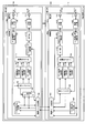
- FIG. 7 is a diagram illustrating the configuration of the wireless communication system according to the first embodiment.
- the wireless communication system 1 includes a pico base station 100 and a macro base station 200.
- the pico base station 100 includes a control unit 100a and a communication unit 100b.
- the control unit 100a includes an interference reduction CCE setting unit 101, a scheduler unit 102, a radio resource control unit 103, an inter-cell interference determination unit 104, an uplink control signal demodulation unit 106, and a data signal generation unit 107.
- control unit 100 a includes a control signal generation unit 108, a reference signal generation unit 109, a channel multiplexing unit 110, an IFFT (Inversed Fast Fourier Transform) unit 111, and a transmission timing control unit 112.
- the communication unit 100 b includes a reception RF unit 105 and a transmission RF (Radio Frequency) unit 113. Each of these components is connected so that signals and data can be input and output in one direction or in both directions.
- the control unit 100a is configured by a digital circuit, a DSP (Digital Signal Processor), a CPU (Central Processing Unit), and the like, and the communication unit 100b is configured by an analog circuit including an amplifier and a filter. .
- the interference reduction CCE setting unit 101 sets the interference reduction CCE based on the radio parameter of the pico cell, and notifies the scheduler unit 102 of the interference reduction CCE.
- the scheduler unit 102 is different from the normal scheduler unit 204 (of the macro base station 200) in that the CCE is allocated to a PDCCH for an interfered pico UE (User Equipment, mobile station) based on the interference reduction CCE. Based on channel quality information (CQI (Channel Quality Indicator)) notified from each mobile station, the scheduler unit 102 allocates frequency resources to data signals for each mobile station, MCS (Modulation and Coding Scheme), information Determine the number of bits. Further, the scheduler unit 102 determines CFI according to the number of mobile stations, and assigns usable CCEs to the PDCCH for each mobile station.
- CQI Channel Quality Indicator
- the radio resource control unit 103 notifies the radio resource control unit 205 of the macro base station 200 of the muting request signal and radio parameters (number of antennas, CFI, cell ID, Ng) necessary for specifying the CCE of the pico cell. . This notification is performed via a wired interface.
- the radio resource control unit 103 receives time shift amount information described later from the radio resource control unit 205.
- the radio resource control unit 103 performs handover control based on the received power (RSRP (Reference Signal Received Power)) information of each cell notified from each mobile station.
- RSRP Reference Signal Received Power
- Inter-cell interference determination section 104 estimates the state of inter-cell interference in each mobile station based on the RSRP information of each cell notified from each mobile station, and applies muting (overwriting with null symbols). It is determined whether or not to request. The determination result is transferred to the radio resource control unit 103 as a muting request signal.
- the transmission timing control unit 112 shifts the transmission timing of the downlink signal in units of OFDM symbols based on the time shift amount information.
- the macro base station 200 includes a control unit 200a and a communication unit 200b.
- the control unit 200a includes a muting processing unit 201, an interference reduction CCE setting unit 202, a muting control unit 203, a scheduler unit 204, a radio resource control unit 205, and an uplink control signal demodulation unit 207.
- the control unit 200a includes a reference signal generation unit 208, a control signal generation unit 209, a data signal generation unit 210, a channel multiplexing unit 211, and an IFFT unit 212.
- the communication unit 200b includes a reception RF unit 206 and a transmission RF unit 213. Each of these components is connected so that signals and data can be input and output in one direction or in both directions.
- the control unit 200a is configured by a digital circuit, a DSP, a CPU, and the like, and the communication unit 200b is configured by an analog circuit that includes an amplifier and a filter.
- the muting processing unit 201 executes muting processing based on the muting control information transferred from the muting control unit 203.
- the interference reduction CCE setting unit 202 sets the interference reduction CCE based on the radio parameter of the pico cell and notifies the muting control unit 203 of the interference reduction CCE.
- the muting control unit 203 determines muting execution based on the muting request, and sets the PDSCH RE of the macro cell corresponding to the pico cell interference reduction CCE as the muting area. Thereafter, the muting control unit 203 notifies the muting processing unit 201 of muting area information. Then, the muting control unit 203 determines the time shift amount of the pico cell, and notifies the radio resource control unit 205 of it.
- the scheduler unit 204 determines allocation of frequency resources to data signals for each mobile station, MCS (Modulation and Coding Scheme), the number of information bits, and the like based on the CQI notified from each mobile station. Further, scheduler section 204 determines CFI according to the number of mobile stations, and assigns usable CCEs to PDCCHs for each mobile station.
- MCS Modulation and Coding Scheme
- the radio resource control unit 205 notifies the time shift amount information to the radio resource control unit 103 of the pico base station 100 via a wired interface.
- Radio resource control unit 205 receives a muting request signal and radio parameters (number of antennas, CFI, cell ID, Ng) of the pico cell from radio resource control unit 103.
- the radio resource control unit 205 controls handover based on the RSRP information of each cell notified from each mobile station.
- the pico base station 100 and the macro base station 200 have a plurality of components having common processing contents.
- the reception RF units 105 and 206 perform conversion from the radio frequency to the baseband on the uplink reception signal, and perform orthogonal demodulation and A / D (Analog to Digital) conversion.
- Reception RF sections 105 and 206 have antennas A1 and A3, respectively, and receive uplink signals.
- Uplink control signal demodulation sections 106 and 207 demodulate the uplink control signal and restore CQI as control information and RSRP of each cell.
- the data signal generators 107 and 210 generate data signals based on resource allocation, MCS information, and the like.
- the control signal generation units 108 and 209 generate a control signal based on control information configured by resource allocation information and the like.
- Reference signal generators 109 and 208 generate reference signals.
- Channel multiplexing sections 110 and 211 frequency multiplex each physical channel.
- the IFFT units 111 and 212 perform inverse Fourier transform (IFFT) and add CP (Cyclic Prefix).
- the transmission RF units 113 and 213 perform D / A conversion and orthogonal modulation, perform conversion from baseband to radio frequency, amplify power, and transmit a downlink signal.
- the transmission RF units 113 and 213 have antennas A2 and A4, respectively, and transmit downlink signals.
- FIG. 8 is a diagram illustrating the configuration of the mobile station according to the first embodiment.
- the mobile station 10 includes a control unit 10a and a communication unit 10b.
- the control unit 10a includes an FFT unit 12, a data signal demodulation unit 13, a control signal demodulation unit 14, a channel estimation unit 15, a CQI calculation unit 16, an RSRP measurement unit 17, and an uplink control signal generation unit 18.
- the communication unit 10 b includes a reception RF unit 11 and a transmission RF unit 19. Each of these components is connected so that signals and data can be input and output in one direction or in both directions.
- the reception RF unit 11 performs conversion from a radio frequency to a baseband on a downlink reception signal, and performs orthogonal demodulation and A / D conversion.
- the reception RF unit 11 receives the downlink signal through the antenna A5.
- the FFT (Fast Fourier Transform) unit 12 detects the cut-out timing of the received signal and removes the CP, and converts the detection result into a received signal in the frequency domain by Fourier transform (FFT), as in a typical OFDM system. To do.
- the data signal demodulator 13 demodulates the data signal extracted from the received signal based on the resource allocation information, and restores the data information.
- the control signal demodulator 14 demodulates the control signal extracted from the received signal, and restores resource allocation information as control information.
- the channel estimation unit 15 obtains a channel estimation value by correlating a reference signal extracted from the received signal with a known reference signal replica. This channel estimation is performed not only for the cell to which the mobile station 10 is connected, but also for the surrounding cells.
- the CQI calculation unit 16 calculates channel quality information (the above-mentioned CQI) using the channel estimation value of the cell to which the mobile station 10 is connected.
- the RSRP measurement unit 17 measures the received power of the reference signal of each cell (the above-mentioned RSRP) using the channel estimation values of the cell to which the mobile station 10 is connected and its neighboring cells.
- the uplink control signal generation unit 18 generates an uplink control signal based on control information configured by CQI and RSRP of each cell.
- the transmission RF unit 19 performs D / A (Digital to Analog) conversion and orthogonal modulation, then performs conversion from baseband to radio frequency, amplifies power, and transmits an uplink signal.
- the transmission RF unit 19 transmits an uplink signal through the antenna A6.
- the control unit 10a is configured by a digital circuit, a DSP, a CPU, and the like
- the communication unit 10b is configured by an analog circuit including an amplifier and a filter.
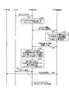
- FIG. 9 is a diagram illustrating the operation of the wireless communication system 1 according to the first embodiment.
- a mobile station connected to the pico base station 100 is a pico UE
- a mobile station connected to the macro base station 200 is a macro UE.
- the pico UE measures the received power of RS (Reference Signal) for the connected cell and the neighboring cells, and reports the measurement result to the pico base station 100 as RSRP.
- RS Reference Signal
- the determination criterion is a predetermined threshold (for example, 1) or more.
- the determination criterion is not limited to the number of interfered pico UEs, and the ratio of the number of interfered pico UEs to the total number of pico UEs may be used.
- the macro base station 200 transmits a muting request signal and radio parameters (number of antennas, CFI, cell ID, Ng).
- the macro base station 200 determines to perform muting based on the muting request signal, and sets a muting area. Specifically, first, the macro base station 200 calculates the number of CCEs that can be allocated in the pico cell based on radio parameters of the pico cell. Next, the macro base station 200 defines a specific CCE (for example, a common SS) of the pico cell as an interference reduction CCE, and sets the corresponding PDSCH RE of the macro cell as a muting area. Then, the macro base station 200 determines the time shift amount in the pico cell. The amount of time shift is determined by, for example, the CFI itself of the macro cell or the upper limit value 3 of the CFI.
- a specific CCE for example, a common SS
- the macro base station 200 determines the time shift amount in the pico cell. The amount of time shift is determined by, for example, the CFI itself of the macro cell or the upper limit value 3 of the CFI.
- the macro base station 200 notifies the pico base station 100 of the time shift amount determined in S4.
- the pico base station 100 changes the transmission timing based on the notified time shift amount, and sets the CFI update period to a long value. This is because the muting area of the macro cell is determined based on the CFI of the pico cell, so that if the CFI is changed frequently, CFI recognition between the macro cell and the pico cell becomes inconsistent. Also, the pico base station 100 sets a specific CCE (for example, a common SS) as the interference reduction CCE based on a rule common to the macro base station 200.
- a specific CCE for example, a common SS
- FIG. 10 is a diagram for explaining a PDCCH multiplexing method in the present embodiment.
- the pico base station 100 sets the CCE as a scheduling target only when the UE-specific SS overlaps the interference-reduced CCE. Assign to PDCCH for interfered pico UE.
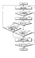
- FIG. 11 is a diagram for explaining a scheduling algorithm executed by the pico base station 100 in S7.
- the pico base station 100 selects a UE that is a candidate for scheduling (S11)
- PDCCH AL aggregation level
- the pico base station 100 can secure a PDCCH resource in the SS of the AL selected in S13. It is determined whether or not there is (S15). As a result of the determination, if the resource can be secured (S15; Yes), the pico base station 100 secures the data signal resource and the PDCCH resource (S16). Thereafter, the pico base station 100 searches for other UEs that are candidates for scheduling (S17), and if there are no other candidate UEs (S17; No), the scheduling process ends.
- the pico base station 100 uses the PDCCH overlapping with the interference reduction CCE in the SS of the AL selected in S13. It is determined whether resources can be secured (S18). As a result of the determination, if the resource can be secured (S18; Yes), the pico base station 100 executes the process of S16 described above. On the other hand, if the resource cannot be secured in S18 (S18; No), the process returns to S11 and the subsequent processing is executed again.
- the pico base station 100 transmits the PDCCH for the interfered pico UE using the interference reduction CCE.
- the macro base station 200 transmits the PDSCH for the macro UE, but mutes the muting area corresponding to the interference reduction CCE when transmitting. By this muting, interference from the macro cell to the PDCCH for the interfered pico UE in the pico cell is reduced.
- the wireless communication system 1 controls the transmission timing in each cell so that the PDCCH of the pico cell and the PDSCH of the macro cell overlap in time.
- the wireless communication system 1 includes a pico base station 100, a macro base station 200, and a pico mobile station 10.
- the pico base station 100 includes a control unit 100a and a communication unit 100b.
- the control unit 100a notifies the macro base station 200 of information used for specifying a PDCCH resource corresponding to a predetermined resource unit.
- the communication unit 100b transmits a control signal to the pico mobile station 10 using the first resource of the PDCCH of the pico cell, which corresponds to at least a part of the predetermined resource unit and is to be decoded by the pico mobile station 10.
- the macro base station 200 includes a communication unit 200b that transmits a null symbol using the second resource of the PDSCH of the macro cell corresponding to the predetermined resource unit.
- the pico mobile station 10 includes a communication unit 10b that receives the control signal transmitted from the pico base station 100 using the first resource and receives the null symbol transmitted from the macro base station 200 using the second resource.
- the predetermined resource unit is one or more CCEs, for example, interference reduction CCEs.
- the first resource is a search space unique to the pico mobile station 10, and is, for example, a resource element to which a CCE in an area where the interference reduction CCE and the user specific search space overlap is mapped in the time / frequency domain.
- the second resource is a resource element to which the interference reduction CCE is mapped in the time / frequency domain.
- Example 2 an example in which the technology of TPC (Transmission Power Control) is applied to the wireless communication system in Example 1 will be described. That is, in the scheduler unit 102 of the pico base station 100 according to the first embodiment, the interfered pico UE is subjected to scheduling only when the UE-specific SS overlaps with the interference reducing CCE. However, since the UE-specific SS has a different starting position for each mobile station, AL, and subframe, the SS for AL that is optimal for the radio channel state does not necessarily overlap with the interference-reducing CCE.
- TPC Transmission Power Control
- the radio communication system uses transmission power control (TPC) together in order to avoid the above-described concern.
- TPC transmission power control
- the scheduler unit 102 controls the transmission power per RE to (AL opt / AL sel ) times.
- PDCCH block errors are suppressed.
- the control unit 100a of the pico base station 100 sets the aggregation level applied to the PDCCH for the mobile station 10 connected to the pico cell to the radio channel state of the mobile station 10. Select tentatively based on.
- the communication unit 100b of the pico base station 100 sets an aggregation level equal to or higher than the provisional value where the UE specific SS overlaps with the interference reduction CCE. Select and send.
- the communication unit 100b selects an aggregation level less than the provisional value at which the UE-specific SS overlaps the interference reduction CCE, and transmits the transmission power with a predetermined value or more.
- the communication unit 100b selects an aggregation level less than the provisional value at which the UE-specific SS overlaps the interference reduction CCE, and transmits the transmission power with a predetermined value or more.
- the third embodiment an example will be described in which the collective muting technology corresponding to a plurality of pico base stations is applied to the wireless communication system in the first embodiment. Unlike the first embodiment, this embodiment assumes a network environment in which a plurality of pico cells are mixed in a macro cell.
- the muting control unit 203 of the macro base station 200 determines how to actually apply muting based on muting request signals notified from a plurality of pico base stations. Is a problem.
- a criterion for such determination includes whether or not the number of pico base stations requesting application of muting exceeds a predetermined threshold.
- the muting control unit 203 may actually apply muting when one or more pico base stations are requested to apply muting.
- the muting control unit 203 may actually apply muting when more than half of the pico base stations are requested to apply muting.
- the next point to be considered in this embodiment is how to set interference reduction CCE in a plurality of pico base stations and how to set a muting area in the macro base station 200.
- the muting control unit 203 first defines a specific CCE (for example, a common SS) of each pico cell as an interference reduction CCE, as in the first embodiment.
- the correspondence between the CCE and the RE position to which the CCE is mapped depends on the number of transmission antennas, CFI, cell ID, and Ng of each pico cell. For this reason, it does not necessarily correspond between each picocell. Therefore, the muting control unit 203 may set the muting area so as to include all REs to which the interference reduction CCEs of the respective pico cells are mapped.
- the macro base station 200 includes the control unit 200a and the communication unit 200b.
- the control unit 200a calculates, for each of the plurality of pico cells, an RE to which the interference reduction CCE of the pico cell is mapped based on the radio parameter of the pico cell.
- the communication unit 200b transmits a null symbol in the same subframe in all REs calculated by the control unit 200a.
- the control unit 100a of the pico base station 100 notifies the macro base station 200 of the radio parameters of the pico cell as information necessary for specifying the resource to which the interference reduction CCE is mapped. I do.
- the control unit 200a of the macro base station 200 identifies the resource to which the pico cell interference reduction CCE is mapped based on the radio parameter information notified from the pico base station 100. As a result, the macro base station 200 can accurately know the position of the RE that is likely to be mapped to the PDCCH of the pico cell.
- the fourth embodiment an example in which the time division muting technology corresponding to a plurality of PeNBs is applied to the wireless communication system in the first embodiment will be described. Unlike the first embodiment, this embodiment assumes a network environment in which a plurality of pico cells are mixed in a macro cell.
- the muting control unit 203 sets the muting area of the macro cell to include all REs to which the interference reduction CCEs of the respective pico cells are mapped. Thereby, collective interference control is possible for the interfered pico UE in a plurality of pico cells.
- the necessary muting area tends to increase. Therefore, in this embodiment, the radio communication system performs interference control on the interfered pico UEs in a plurality of pico cells while keeping a necessary muting area small.
- the muting control unit of the macro base station performs muting specialized for individual picocells for each subframe.
- FIG. 12 is a diagram illustrating a configuration of a wireless communication system according to the fourth embodiment.
- the wireless communication system 2 includes a pico base station 300 and a macro base station 400.
- the pico base station 300 includes a control unit 300a and a communication unit 300b.
- the control unit 300a includes an interference reduction CCE setting unit 301, a scheduler unit 302, a radio resource control unit 303, an inter-cell interference determination unit 304, an uplink control signal demodulation unit 306, and a data signal generation unit 307.
- control unit 300 a includes a control signal generation unit 308, a reference signal generation unit 309, a channel multiplexing unit 310, an IFFT unit 311, and a transmission timing control unit 312.
- the communication unit 300b includes a reception RF unit 305 and a transmission RF unit 313. Each of these components is connected so that signals and data can be input and output in one direction or in both directions.
- the macro base station 400 includes a control unit 400a and a communication unit 400b.
- the control unit 400a includes a muting processing unit 401, an interference reduction CCE setting unit 402, a muting control unit 403, a scheduler unit 404, a radio resource control unit 405, and an uplink control signal demodulation unit 407.
- the control unit 400a includes a reference signal generation unit 408, a control signal generation unit 409, a data signal generation unit 410, a channel multiplexing unit 411, and an IFFT unit 412.
- the communication unit 400b includes a reception RF unit 406 and a transmission RF unit 413. Each of these components is connected so that signals and data can be input and output in one direction or in both directions.
- the wireless communication system 2 has the same configuration as the wireless communication system 1 in the first embodiment. Therefore, the same components are denoted by the same reference numerals at the end, and detailed description thereof is omitted.
- the pico base station 300 and the macro base station 400 in the fourth embodiment are components corresponding to the pico base station 100 and the macro base station 200 in the first embodiment, respectively.
- the control unit 300a and the communication unit 300b of the pico base station 300 correspond to the control unit 100a and the communication unit 100b of the pico base station 100, respectively.
- the control unit 400a and the communication unit 400b of the macro base station 400 correspond to the control unit 200a and the communication unit 200b of the macro base station 200, respectively.
- Interference reduction CCE setting section 301, scheduler section 302, and radio resource control section 303 of pico base station 300 correspond to interference reduction CCE setting section 101, scheduler section 102, and radio resource control section 103 of pico base station 100, respectively.
- the inter-cell interference determination unit 304, the reception RF unit 305, the uplink control signal demodulation unit 306, and the data signal generation unit 307 are the inter-cell interference determination unit 104, the reception RF unit 105, the uplink control signal demodulation unit 106, and the data signal. Each corresponds to the generation unit 107.
- control signal generation unit 308, the reference signal generation unit 309, and the channel multiplexing unit 310 correspond to the control signal generation unit 108, the reference signal generation unit 109, and the channel multiplexing unit 110, respectively.
- the IFFT unit 311, the transmission timing control unit 312, and the transmission RF unit 313 correspond to the IFFT unit 111, the transmission timing control unit 112, and the transmission RF unit 113, respectively.
- the muting processing unit 401 and the interference reduction CCE setting unit 402 of the macro base station 400 correspond to the muting processing unit 201 and the interference reduction CCE setting unit 202 of the macro base station 200, respectively.
- the muting control unit 403, the scheduler unit 404, and the radio resource control unit 405 correspond to the muting control unit 203, the scheduler unit 204, and the radio resource control unit 205, respectively.
- reception RF section 406, uplink control signal demodulation section 407, and reference signal generation section 408 correspond to reception RF section 206, uplink control signal demodulation section 207, and reference signal generation section 208, respectively.
- control signal generation unit 409, the data signal generation unit 410, and the channel multiplexing unit 411 correspond to the control signal generation unit 209, the data signal generation unit 210, and the channel multiplexing unit 211, respectively.
- the IFFT unit 412 and the transmission RF unit 413 correspond to the IFFT unit 212 and the transmission RF unit 213, respectively.
- the configuration of the mobile station is the same as that in the first embodiment, and thus the description thereof is omitted.
- Inter-cell interference determination section 304 of pico base station 300 estimates the state of inter-cell interference in each mobile station based on the RSRP information of each cell notified from each mobile station.
- the inter-cell interference determination unit 304 determines whether or not to apply muting based on the estimation result, and generates the number of interfered UEs.
- the inter-cell interference determination unit 304 transfers the interfered UE number information to the radio resource control unit 303.
- the radio resource control unit 303 of the pico base station 300 uses the number of interfered UE information and radio parameters (number of antennas, CFI, cell ID, Ng) necessary for grasping the CCE of the pico cell, and the radio resource of the macro base station 400.
- Radio resource control section 303 receives time shift amount information and interference reduction subframe information for each pico cell from macro base station 400.
- the scheduler section 302 of the pico base station 300 assigns a CCE to the PDCCH for the interfered pico UE based on the interference reduction subframe information and the interference reduction CCE for each pico cell.
- the muting control unit 403 of the macro base station 400 generates interference reduction subframe information for each pico cell based on the number of interfered UEs of each pico cell.
- the muting control unit 403 sets the PDSCH RE of the macro cell corresponding to the interference reduction CCE of each pico cell as a muting area for each pico cell. Then, the muting control unit 403 notifies the muting processing unit 401 of the muting area information for the pico cell in which the interference reduction subframe is set for each subframe.
- the muting control unit 403 determines a time shift amount common to each pico cell, and notifies the radio resource control unit 405 of the time shift amount together with interference reduction subframe information for each pico cell.
- the radio resource control unit 405 of the macro base station 400 notifies the radio resource control unit 303 of each pico base station 300 of the time shift amount information and the interference reduction subframe information for each pico cell via the wired interface.
- Radio resource control section 405 receives the number of interfered UEs and radio parameters (number of antennas, CFI, cell ID, Ng) of each pico cell from pico base station 300.
- Radio resource control section 405 transmits and receives various data and signals to and from pico base station 500.
- FIG. 13 is a diagram illustrating the operation of the wireless communication system 2 according to the fourth embodiment.
- the mobile station connected to the pico base station 300 is the pico UE 10
- the mobile station connected to the pico base station 500 is the pico UE 20
- the mobile connected to the macro base station 400 is Let the station be a macro UE.
- a pico cell formed by the pico base station 300 is referred to as a pico cell C1
- a pico cell formed by the pico base station 500 is referred to as a pico cell C2.
- the pico UE 10 measures the received power of the RS for the connected cell and the neighboring cells, and reports the measurement result to the pico base station 300 as RSRP. Also in the pico UE 20, the same processing as S21 is executed, and the RSRP of each cell is reported to the pico base station 500 (S22).
- the pico base station 300 estimates the state of inter-cell interference in each pico UE based on the RSRP information of each cell notified from each pico UE, and issues a muting request based on the estimation result. Determine whether to do it.
- the same estimation process and determination process are executed (S24). Detailed processing contents are the same as the processing of S2 of FIG.
- the pico base station 300 when requesting the application of muting, gives the macro base station 400 information on the number of interfered UEs and radio parameters necessary for grasping the CCE of the pico cell C1 (number of antennas, CFI, cell ID, Ng).
- the interfered UE number information the number of interfered pico UEs, which is a criterion for determining whether or not to make a muting request, is used.
- the number of interfered UEs is not limited to the number, and a ratio of the number of interfered pico UEs to the total number of pico UEs may be used.
- the process similar to S25 is performed from the pico base station 500 to the macro base station.
- the macro base station 400 determines a muting application method based on the interfered UE number information and the pico cell information from the plurality of pico base stations 300 and 500. Specifically, the macro base station 400 defines an interference reduction CCE for each target pico cell, and sets the PDSCH RE of the macro cell corresponding to this as a muting area. Further, the macro base station 400 determines the target interference reduction CCE for the pico cell and the subframe in which the muting area is set (interference reduction subframe) based on the interfered UE number information.
- the macro base station 400 sets the ratio of the number of interference reduction subframes for the picocells C1 and C2 to ( p_mute1: p_mute2). Based on the ratio, macro base station 400 generates information (interference reduction subframe information) indicating in which subframe the interference reduction subframes for pico cells C1 and C2 are located.
- FIG. 14 is a diagram showing an example of the interference reduction subframe information in the present embodiment.
- the corresponding interference reduction subframe for the pico cell is set.
- the macro base station 400 determines a common time shift amount in each of the pico cells C1 and C2. This amount of time shift is determined by, for example, the CFI itself of the macro cell or the upper limit value 3 of the CFI.
- the macro base station 400 notifies the pico base station 500 of the interference reduction subframe information and the time shift amount determined in S27. Such information is also notified from the macro base station 400 to the pico base station 300 (S29).
- the pico base station 300 changes the transmission timing based on the time shift amount notified from the macro base station 400, and sets the CFI update period to a long value. Further, the pico base station 300 sets a specific CCE (for example, a common SS) as the interference reduction CCE of the pico cell C1 based on a rule common to the macro base station 400.
- a specific CCE for example, a common SS
- the pico base station 300 relates to the interfered pico UE only when the pico cell interference reduction subframe is set and the UE-specific SS overlaps with the interference reduction CCE of the pico cell C1. Is the scheduling target.
- the pico base station 300 allocates a part of the overlapping CCEs to the PDCCH for the interfered pico UE.
- FIG. 15 is a diagram for explaining a scheduling algorithm of the pico base stations 300 and 500 according to the fourth embodiment.
- FIG. 15 is the same as FIG. 11 except that the determination process of step S49 is newly provided, and thus detailed description of FIG. 15 is omitted.
- Steps S41 to S48 in FIG. 15 correspond to steps S11 to S18 in FIG. 11, respectively.
- the PDCCH resource be secured regardless of the determination result? It was assumed that a determination (S15 or S18) was made.
- Example 4 when the UE selected in S41 is an interfered pico UE (S44; Yes), each pico base station 300, 500 has a corresponding subframe for the corresponding pico cell. It is determined whether the subframe is an interference reduction subframe (S49). As a result of the determination, if the subframe is an interference reduction subframe (S49; Yes), the process proceeds to S48 and subsequent steps.
- the pico base station 500 performs the same processing as S30 and S31 described above based on the interference reduction subframe information and the time shift amount notified in S28 (S32, S33).
- the pico base station 300 transmits the PDCCH for the interfered pico UE using the interference reduction CCE for the pico cell C1 in the interference reduction subframe for the pico cell C1.
- the macro base station 400 transmits the PDSCH
- the muting area corresponding to the interference reducing CCE for the pico cell C1 is muted (S35).
- the interference from the macro cell to the PDCCH for the interfered pico UE in the pico cell C1 is reduced.
- the pico base station 500 transmits the PDCCH for the interfered pico UE using the interference reduction CCE for the pico cell C2 in the interference reduction subframe for the pico cell C2.
- the macro base station 400 transmits the PDSCH
- the muting area corresponding to the interference reducing CCE for the pico cell C2 is muted (S37).
- the interference from the macro cell to the PDCCH for the interfered pico UE in the pico cell C2 is reduced.
- the representative pico cells C1 and C2 have been described.
- the RE position to which the PDCCH in the pico cells other than these pico cells is mapped partially overlaps with the muting area. For this reason, there is an effect that interference with these PDCCHs is also partially reduced.
- the wireless communication system 2 includes the plurality of pico base stations 300 and 500.
- the pico base station 300 includes a control unit 300a and a communication unit 300b.
- the control unit 300a performs control so as to notify the macro base station 400 of information necessary for specifying the CCE to which the interference reducing CCE is mapped and the number of interfered UEs.
- the UE-specific search space of the mobile station connected to the picocells C1 and C2 overlaps with the interference reduction CCE.
- the communication unit 300b performs transmission using the PDCCH for the mobile station using the interference reduction CCE in the overlapping region.
- the macro base station 400 includes a control unit 400a and a communication unit 400b.
- the control unit 400a sets interference reduction subframes for the pico cells C1 and C2 based on the number of interfered UE information notified from the plurality of pico base stations 300 and 500, and sets the interference reduction subframe information for each pico cell. Control to notify the base stations 300 and 500 is performed.
- the communication unit 400b transmits a null symbol in a resource to which the interference reduction CCE of the pico cell is mapped in the interference reduction subframe for each of the pico cells C1 and C2.
- the time division muting technique according to the plurality of pico base stations can be applied to the wireless communication system in the first embodiment. Therefore, the interference which one macrocell gives to PDCCH of several picocells C1 and C2 is reduced. On the other hand, regardless of the number of pico cells, the reception characteristics of the PDSCH of the macro cell are maintained.
- the control unit 300a of the pico base station 300 performs control to notify the macro base station 400 of information based on the number of UEs whose radio channel state is equal to or lower than a predetermined quality as the interfered UE number information.
- the radio channel state is equal to or lower than a predetermined quality, for example, when the measured reception level is equal to or lower than a predetermined value.
- the control part 300a can notify more suitable information which shows how many mobile stations which receive a big interference exist.
- the control unit 400a of the macro base station 400 based on the ratio between the pico cells C1 and C2 related to the value indicated by the number of interfered UEs, the pico cells C1 related to the number of interference reduction subframes, Set the ratio between C2. Thereby, it is possible to prevent the PDCCH transmission opportunities of the pico cells C1 and C2 from being biased between cells.
- the control unit 400a of the macro base station 400 sets the interference reduction subframes for the pico cells C1 and C2 so as not to overlap each other. Thereby, the radio
- the communication unit 400b of the macro base station 400 is triggered by the request from the pico base station that has requested transmission of the null symbol among the plurality of pico base stations 300 and 500 as a trigger. Null symbols are transmitted to 300 mobile stations 10. As a result, muting is executed only for the pico base station that requires interference control. Therefore, the processing load of the macro base station 400 associated with the interference control is reduced as compared with the case where muting is executed for all the pico base stations.
- the radio communication system 1 sets the interference reduction CCE to, for example, a common SS according to a common rule between the macro base station and the pico base station.
- the interference reduction CCE is fixedly set, for example, when the number of interfered pico UEs in the pico cell is large, the radio communication system 1 becomes difficult to secure the PDCCH resources of the interfered pico UE, and the interfered pico UE There is a concern that the throughput of will decrease.
- the radio communication system 1 can easily secure PDCCH resources of the interfered pico UE, but the amount of PDSCH RE muted in the macro cell becomes excessive. Therefore, in the wireless communication system according to the present embodiment, the interference reduction CCE is controlled according to the communication state of the pico cell.
- FIG. 16 is a diagram illustrating the configuration of the wireless communication system according to the fifth embodiment.
- the wireless communication system 3 includes a pico base station 600 and a macro base station 700.
- the pico base station 600 includes a control unit 600a and a communication unit 600b.
- the control unit 600a includes a scheduler unit 602, a radio resource control unit 603, an inter-cell interference determination unit 604, an uplink control signal demodulation unit 606, and a data signal generation unit 607.
- the control unit 600a includes a control signal generation unit 608, a reference signal generation unit 609, a channel multiplexing unit 610, an IFFT unit 611, and a transmission timing control unit 612.
- the communication unit 600b includes a reception RF unit 605 and a transmission RF unit 613. Each of these components is connected so that signals and data can be input and output in one direction or in both directions.
- the macro base station 700 includes a control unit 700a and a communication unit 700b.
- the control unit 700a includes a muting processing unit 701, an interference reduction CCE setting unit 702, a muting control unit 703, a scheduler unit 704, a radio resource control unit 705, and an uplink control signal demodulation unit 707.
- the control unit 700a includes a reference signal generation unit 708, a control signal generation unit 709, a data signal generation unit 710, a channel multiplexing unit 711, and an IFFT unit 712.
- the communication unit 700b includes a reception RF unit 706 and a transmission RF unit 713. Each of these components is connected so that signals and data can be input and output in one direction or in both directions.
- the wireless communication system 3 has the same configuration as the wireless communication system 1 in the first embodiment. Therefore, the same components are denoted by the same reference numerals at the end, and detailed description thereof is omitted.
- the pico base station 600 and the macro base station 700 in the fifth embodiment are components corresponding to the pico base station 100 and the macro base station 200 in the first embodiment, respectively.
- the control unit 600a and the communication unit 600b of the pico base station 600 correspond to the control unit 100a and the communication unit 100b of the pico base station 100, respectively.
- the control unit 700a and the communication unit 700b of the macro base station 700 correspond to the control unit 200a and the communication unit 200b of the macro base station 200, respectively.
- the scheduler unit 602 and the radio resource control unit 603 of the pico base station 600 correspond to the scheduler unit 102 and the radio resource control unit 103 of the pico base station 100, respectively.
- the inter-cell interference determination unit 604, the reception RF unit 605, the uplink control signal demodulation unit 606, and the data signal generation unit 607 are the inter-cell interference determination unit 104, the reception RF unit 105, the uplink control signal demodulation unit 106, and the data signal. Each corresponds to the generation unit 107.
- the control signal generation unit 608, the reference signal generation unit 609, and the channel multiplexing unit 610 correspond to the control signal generation unit 108, the reference signal generation unit 109, and the channel multiplexing unit 110, respectively.
- the IFFT unit 611, the transmission timing control unit 612, and the transmission RF unit 613 correspond to the IFFT unit 111, the transmission timing control unit 112, and the transmission RF unit 113, respectively.
- the muting processing unit 701 and the interference reduction CCE setting unit 702 of the macro base station 700 correspond to the muting processing unit 201 and the interference reduction CCE setting unit 202 of the macro base station 200, respectively.
- the muting control unit 703, the scheduler unit 704, and the radio resource control unit 705 correspond to the muting control unit 203, the scheduler unit 204, and the radio resource control unit 205, respectively.
- reception RF section 706, uplink control signal demodulation section 707, and reference signal generation section 708 correspond to reception RF section 206, uplink control signal demodulation section 207, and reference signal generation section 208, respectively.
- control signal generation unit 709, the data signal generation unit 710, and the channel multiplexing unit 711 correspond to the control signal generation unit 209, the data signal generation unit 210, and the channel multiplexing unit 211, respectively.
- the IFFT unit 712 and the transmission RF unit 713 correspond to the IFFT unit 212 and the transmission RF unit 213, respectively.
- the configuration of the mobile station is the same as that in the first embodiment, and thus the description thereof is omitted.
- the interference reduction CCE setting unit 702 of the macro base station 700 adjusts the interference reduction CCE based on the interfered UE number information and the pico cell information, and uses the result as the interference reduction CCE information, and the muting control unit 703 and the radio resource control. Section 705 is notified.
- the radio resource control unit 705 of the macro base station 700 notifies the radio resource control unit 603 of the pico base station 600 of the time shift amount and the interference reduction CCE information.
- the radio resource control unit 603 of the pico base station 600 notifies the interference reduction CCE information to the scheduler unit 602.
- FIG. 17 is a diagram illustrating the operation of the wireless communication system 3 according to the fifth embodiment.
- FIG. 17 is the same as FIG. 9 except for steps S53 to S55. Therefore, detailed description of FIG. 17 is omitted, and differences from the first embodiment will be described. Steps S51 to S59 in FIG. 17 correspond to steps S1 to S9 shown in FIG. 9, respectively.
- the pico base station 600 notifies the macro base station 700 of pico cell information (number of antennas, CFI, cell ID, Ng) and interfered UE (mobile station) number information.
- the macro base station 700 adjusts the number of interference-reduced CCEs based on the interfered UE number information notified from the pico base station 600 (S54). Specifically, the macro base station 700 increases the number of interference-reduced CCEs when the number of interfered UEs indicated by the information on the number of interfered UEs or the ratio thereof is a predetermined value or more.
- the macro base station 700 decreases the number of interference-reduced CCEs.
- the macro base station 700 notifies the pico base station 600 together with the amount of time shift as information on the number of interference-reduced CCEs adjusted in S54 as interference-reduced CCE information.
- the pico base station 600 sets the interference reduction CCE according to the interference reduction CCE information notified from the macro base station 700 in S55.
- the wireless communication system 3 includes the pico base station 600 and the macro base station 700.
- the pico base station 600 includes a control unit 600a.
- the control unit 600a notifies the interfered UE number information to the macro base station 700, and sets the interference reduction CCE according to the interference reduction CCE information notified from the macro base station 700.
- the macro base station 700 has a control unit 700a.
- the control unit 700a adjusts the number of interference-reduced CCEs based on the number of interfered UEs notified from the pico base station 600 and notifies the pico base station 600 of interference-reduced CCE information based on the number of interference-reduced CCEs. .
- the radio communication system 3 can sufficiently secure the PDCCH resources of the interfered pico UE in the pico cell. Further, in the macro cell, the amount of PDSCH RE to be muted can be minimized.
- the control unit 700a of the macro base station 700 increases the number of interference-reduced CCEs when the number of interfered UEs is equal to or greater than a predetermined value, and when the number of interfered UEs is less than the predetermined value, Control is performed to reduce the number of interference-reducing CCEs.
- the number of interference reduction CCEs is appropriately adjusted according to the communication status of the pico cell, interference reduction CCE control without excess or deficiency is realized for each pico base station.
- the wireless communication system disclosed in the present application reduces interference between the macro cell and the pico cell.
- the radio communication systems 1, 2, and 3 are not limited to this, and can also be applied as a technique for reducing interference between a macro cell and a femto cell, or interference between a pico cell and a femto cell.
- Wireless communication system 10 Mobile station 10a Control unit 10b Communication unit 11 Reception RF unit 12 FFT unit 13 Data signal demodulation unit 14 Control signal demodulation unit 15 Channel estimation unit 16 CQI calculation unit 17 RSRP measurement unit 18 Uplink control signal Generation unit 19 Transmission RF unit 100, 300, 500, 600 Pico base station 100a, 300a, 600a Control unit 100b, 300b, 600b Communication unit 101, 301 Interference reduction CCE setting unit 102, 302, 602 Scheduler unit 103, 303, 603 Radio resource control unit 104, 304, 604 Inter-cell interference determination unit 105, 305, 605 Reception RF unit 106, 306, 606 Uplink control signal demodulation unit 107, 307, 607 Data signal generation unit 108, 308, 608 Control signal generation unit 109,309,60 Reference signal generation unit 110, 310, 610 Channel multiplexing unit 111, 311, 611 IFFT unit 112, 312, 612 Transmission timing control unit 113, 313, 613 Transmission RF unit 200
Abstract
Description
10 移動局
10a 制御部
10b 通信部
11 受信RF部
12 FFT部
13 データ信号復調部
14 制御信号復調部
15 チャネル推定部
16 CQI算出部
17 RSRP測定部
18 上り制御信号生成部
19 送信RF部
100,300,500,600 ピコ基地局
100a,300a,600a 制御部
100b,300b,600b 通信部
101,301 干渉低減CCE設定部
102,302,602 スケジューラ部
103,303,603 無線リソース制御部
104,304,604 セル間干渉判定部
105,305,605 受信RF部
106,306,606 上り制御信号復調部
107,307,607 データ信号生成部
108,308,608 制御信号生成部
109,309,609 参照信号生成部
110,310,610 チャネル多重部
111,311,611 IFFT部
112,312,612 送信タイミング制御部
113,313,613 送信RF部
200,400,700 マクロ基地局
200a,400a,700a 制御部
200b,400b,700b 通信部
201,401,701 ミューティング処理部
202,402,702 干渉低減CCE設定部
203,403,703 ミューティング制御部
204,404,704 スケジューラ部
205,405,705 無線リソース制御部
206,406,706 受信RF部
207,407,707 上り制御信号復調部
208,408,708 参照信号生成部
209,409,709 制御信号生成部
210,410,710 データ信号生成部
211,411,711 チャネル多重部
212,412,712 IFFT部
213,413,713 送信RF部
C1,C2 ピコセル 1, 2 and 3 Wireless communication system 10 Mobile station 10a Control unit 10b Communication unit 11 Reception RF unit 12 FFT unit 13 Data signal demodulation unit 14 Control signal demodulation unit 15 Channel estimation unit 16 CQI calculation unit 17 RSRP measurement unit 18 Uplink control signal Generation unit 19 Transmission RF unit 100, 300, 500, 600 Pico base station 100a, 300a, 600a Control unit 100b, 300b, 600b Communication unit 101, 301 Interference reduction CCE setting unit 102, 302, 602 Scheduler unit 103, 303, 603 Radio resource control unit 104, 304, 604 Inter-cell interference determination unit 105, 305, 605 Reception RF unit 106, 306, 606 Uplink control signal demodulation unit 107, 307, 607 Data signal generation unit 108, 308, 608 Control signal generation unit 109,309,60 Reference signal generation unit 110, 310, 610 Channel multiplexing unit 111, 311, 611 IFFT unit 112, 312, 612 Transmission timing control unit 113, 313, 613 Transmission RF unit 200, 400, 700 Macro base station 200a, 400a, 700a Control Unit 200b, 400b, 700b communication unit 201, 401, 701 muting processing unit 202, 402, 702 interference reduction CCE setting unit 203, 403, 703 muting control unit 204, 404, 704 scheduler unit 205, 405, 705 radio resource Control unit 206, 406, 706 Reception RF unit 207, 407, 707 Uplink control signal demodulation unit 208, 408, 708 Reference signal generation unit 209, 409, 709 Control signal generation unit 210, 410, 710 Data signal generation unit 211,411,711 Channel multiplexing unit 212,412,712 IFFT unit 213,413,713 Transmission RF unit C1, C2 Picocell
Claims (16)
- 第1セルの制御チャネルと第2セルのデータチャネルとが時間的に重なるように、各セルにおける送信タイミングを制御する無線通信システムであって、
前記第1セルの基地局は、
所定のリソース単位に対応する、前記第1セルの制御チャネルのリソースの特定に用いられる情報を、前記第2セルの基地局に通知する第1制御部と、
前記所定のリソース単位の少なくとも一部に対応し、かつ、前記第1セルの移動局の復号対象である、前記第1セルの制御チャネルの第1リソースを用いて、前記第1セルの移動局に制御信号を送信する第1通信部とを有し、
前記第2セルの基地局は、
前記所定のリソース単位に対応する、前記第2セルのデータチャネルの第2リソースを用いて、ヌルシンボルを送信する第2通信部を有し、
前記第1セルの移動局は、
前記第1セルの基地局から送信された前記制御信号を、前記第1リソースにより受信すると共に、前記第2セルの基地局から送信された前記ヌルシンボルを、前記第2リソースにより受信する第3通信部を有することを特徴とする無線通信システム。 A wireless communication system that controls transmission timing in each cell such that a control channel of a first cell and a data channel of a second cell overlap in time,
The base station of the first cell is
A first control unit for notifying a base station of the second cell of information used for specifying a resource of the control channel of the first cell corresponding to a predetermined resource unit;
The mobile station of the first cell using the first resource of the control channel of the first cell, which corresponds to at least a part of the predetermined resource unit and is a decoding target of the mobile station of the first cell A first communication unit that transmits a control signal to
The base station of the second cell is
A second communication unit that transmits a null symbol using a second resource of the data channel of the second cell corresponding to the predetermined resource unit;
The mobile station of the first cell is
The control signal transmitted from the base station of the first cell is received by the first resource, and the null symbol transmitted from the base station of the second cell is received by the second resource. A wireless communication system comprising a communication unit. - 前記所定のリソース単位は、一以上のCCE(Control Channel Element)であり、
前記第1リソースは、前記第1セルの移動局固有のサーチスペースであることを特徴とする請求項1に記載の無線通信システム。 The predetermined resource unit is one or more CCE (Control Channel Element),
The wireless communication system according to claim 1, wherein the first resource is a search space specific to the mobile station of the first cell. - 前記第2セルの基地局は、
複数の第1セルそれぞれについて、前記第1セルの無線パラメータに基づいて、前記第1セルの所定のリソース単位がマッピングされるリソースを算出する第2制御部を更に有し、
前記第2セルの基地局の第2通信部は、前記第2制御部により算出された全てのリソースにおいて、同一のサブフレームによりヌルシンボルを送信することを特徴とする請求項1に記載の無線通信システム。 The base station of the second cell is
For each of a plurality of first cells, further comprising a second control unit that calculates a resource to which a predetermined resource unit of the first cell is mapped based on a radio parameter of the first cell;
2. The radio according to claim 1, wherein the second communication unit of the base station of the second cell transmits a null symbol in the same subframe in all resources calculated by the second control unit. Communications system. - 前記無線通信システムは、前記第1セルの基地局を複数有し、
前記第1セルの基地局の第1制御部は、
前記所定のリソース単位がマッピングされるリソースの特定に必要な情報と被干渉移動局数情報とを、前記第2セルの基地局に通知し、
前記第1セルの基地局の第1通信部は、
前記第2セルの基地局から通知された干渉低減サブフレーム情報の示す、前記第1セル用の干渉低減サブフレームにおいて、前記第1セルに接続する移動局の移動局固有復号対象リソースが前記所定のリソース単位と重なる場合、重なる領域内の所定のリソース単位を用いて、前記移動局用の制御チャネルによる送信を行い、
前記第2セルの基地局は、
複数の第1セルの基地局から通知された被干渉移動局数情報に基づいて、各第1セル用の干渉低減サブフレームを設定すると共に、前記干渉低減サブフレーム情報を各第1セルの基地局に通知する第2制御部を更に有し、
前記第2セルの基地局の第2通信部は、
前記各第1セル用の干渉低減サブフレームにおいて前記第1セルの所定のリソース単位がマッピングされるリソースにおいて、ヌルシンボルを送信することを特徴とする請求項1に記載の無線通信システム。 The wireless communication system has a plurality of base stations of the first cell,
The first control unit of the base station of the first cell,
Notifying the base station of the second cell of information necessary for identifying the resource to which the predetermined resource unit is mapped and the number of interfered mobile station information,
The first communication unit of the base station of the first cell is
In the interference reduction subframe for the first cell indicated by the interference reduction subframe information notified from the base station of the second cell, the mobile station specific decoding target resource of the mobile station connected to the first cell is the predetermined cell. When using a predetermined resource unit in the overlapping area, transmission using the control channel for the mobile station,
The base station of the second cell is
Based on the number information of interfered mobile stations notified from a plurality of base stations of the first cell, an interference reduction subframe for each first cell is set, and the interference reduction subframe information is set to the base of each first cell. A second control unit for notifying the station;
The second communication unit of the base station of the second cell is
The radio communication system according to claim 1, wherein a null symbol is transmitted in a resource to which a predetermined resource unit of the first cell is mapped in the interference reduction subframe for each first cell. - 前記第1セルの基地局の第1制御部は、
前記被干渉移動局数情報として、無線チャネル状態が所定品質以下の移動局数に基づく情報を前記第2セルの基地局に通知することを特徴とする請求項4に記載の無線通信システム。 The first control unit of the base station of the first cell,
5. The radio communication system according to claim 4, wherein the base station of the second cell is notified of information based on the number of mobile stations whose radio channel state is equal to or lower than a predetermined quality as the number of interfered mobile station information. - 前記第2セルの基地局の第2制御部は、
前記被干渉移動局数情報が示す値に関する各第1セル間の比率に基づいて、前記干渉低減サブフレームの個数に関する各第1セル間の比率を設定することを特徴とする請求項4に記載の無線通信システム。 The second control unit of the base station of the second cell,
The ratio between the first cells regarding the number of the interference reduction subframes is set based on the ratio between the first cells regarding the value indicated by the number information of the interfered mobile stations. Wireless communication system. - 前記第2セルの基地局の第2制御部は、
前記各第1セル用の干渉低減サブフレームを互いに重複しないように設定することを特徴とする請求項4に記載の無線通信システム。 The second control unit of the base station of the second cell,
The radio communication system according to claim 4, wherein the interference reduction subframes for the first cells are set so as not to overlap each other. - 前記第1セルの基地局の第1制御部は、
前記所定のリソース単位がマッピングされるリソースの特定に必要な情報として、前記第1セルの無線パラメータを、前記第2セルの基地局に通知し、
前記第2セルの基地局の第2制御部は、
前記第1セルの基地局から通知された無線パラメータの情報に基づいて、前記第1セルの所定のリソース単位がマッピングされるリソースを特定することを特徴とする請求項4に記載の無線通信システム。 The first control unit of the base station of the first cell,
As information necessary for specifying the resource to which the predetermined resource unit is mapped, the radio parameter of the first cell is notified to the base station of the second cell;
The second control unit of the base station of the second cell,
5. The radio communication system according to claim 4, wherein a resource to which a predetermined resource unit of the first cell is mapped is specified based on radio parameter information notified from the base station of the first cell. . - 前記第1セルの基地局の第1制御部は、
前記第1セルに接続する移動局用の制御チャネルに適用するアグリゲーションレベルを、前記移動局の無線チャネル状態に基づいて暫定的に選択し、
前記第1セルの基地局の第1通信部は、
前記移動局の暫定的なアグリゲーションレベルに対する移動局固有復号対象リソースが前記所定のリソース単位と重ならない場合に、前記移動局固有復号対象リソースが前記所定のリソース単位と重なる、暫定値以上のアグリゲーションレベルを選択して送信する、または、前記移動局固有復号対象リソースが前記所定のリソース単位と重なる、前記暫定値未満のアグリゲーションレベルを選択し送信電力を所定値以上にして送信することを特徴とする請求項4に記載の無線通信システム。 The first control unit of the base station of the first cell,
Temporarily selecting an aggregation level to be applied to a control channel for a mobile station connected to the first cell based on a radio channel state of the mobile station,
The first communication unit of the base station of the first cell is
When the mobile station specific decoding target resource for the provisional aggregation level of the mobile station does not overlap with the predetermined resource unit, the mobile station specific decoding target resource overlaps the predetermined resource unit with an aggregation level equal to or higher than the provisional value. Is selected or transmitted, or an aggregation level less than the provisional value, in which the mobile station specific decoding target resource overlaps the predetermined resource unit, is selected and transmitted with a transmission power equal to or higher than a predetermined value. The wireless communication system according to claim 4. - 前記第1セルの基地局の第1制御部は、
被干渉移動局数を、前記第2セルの基地局に通知すると共に、前記第2セルの基地局から通知された干渉低減リソース単位情報に従って、所定のリソース単位を設定し、
前記第2セルの基地局の第2制御部は、
前記第1セルの基地局から通知された被干渉移動局数に基づいて、所定のリソース単位数を調整すると共に、所定のリソース単位数に基づく干渉低減リソース単位情報を、前記第1セルの基地局に通知することを特徴とする請求項1に記載の無線通信システム。 The first control unit of the base station of the first cell,
Notifying the base station of the second cell of the number of interfered mobile stations, and setting a predetermined resource unit according to the interference reduction resource unit information notified from the base station of the second cell,
The second control unit of the base station of the second cell,
A predetermined resource unit number is adjusted based on the number of interfered mobile stations notified from the base station of the first cell, and interference reduction resource unit information based on the predetermined resource unit number is adjusted to the base of the first cell. The wireless communication system according to claim 1, wherein the wireless communication system is notified to a station. - 前記第2セルの基地局の第2制御部は、
前記被干渉移動局数が所定値以上の場合には、前記所定のリソース単位数を増加させると共に、前記被干渉移動局数が前記所定値未満の場合には、前記所定のリソース単位数を減少させることを特徴とする請求項10に記載の無線通信システム。 The second control unit of the base station of the second cell,
When the number of interfered mobile stations is greater than or equal to a predetermined value, the predetermined number of resource units is increased, and when the number of interfered mobile stations is less than the predetermined value, the predetermined number of resource units is decreased. The wireless communication system according to claim 10, wherein: - 前記第2セルの基地局の第2通信部は、
複数の第1セルの基地局のうち、前記ヌルシンボルの送信を要求した第1セルの基地局からの当該要求を契機として、前記第1セルの基地局の移動局に前記ヌルシンボルを送信することを特徴とする請求項4に記載の無線通信システム。 The second communication unit of the base station of the second cell is
The null symbol is transmitted to the mobile station of the base station of the first cell, triggered by the request from the base station of the first cell that requested the transmission of the null symbol among a plurality of base stations of the first cell. The wireless communication system according to claim 4. - 第1セルの制御チャネルと第2セルのデータチャネルとが時間的に重なるように、各セルにおける送信タイミングを制御する無線通信システムにおける前記第1セルの基地局であって、
所定のリソース単位に対応する、前記第1セルの制御チャネルのリソースの特定に用いられる情報を、前記第2セルの基地局に通知する制御部と、
前記所定のリソース単位の少なくとも一部に対応し、かつ、前記第1セルの移動局の復号対象である、前記第1セルの制御チャネルの第1リソースを用いて、前記第1セルの移動局に制御信号を送信する通信部と
を有することを特徴とする基地局。 A base station of the first cell in a wireless communication system that controls transmission timing in each cell such that a control channel of the first cell and a data channel of the second cell overlap in time;
A control unit for notifying a base station of the second cell of information used for identifying a resource of the control channel of the first cell corresponding to a predetermined resource unit;
The mobile station of the first cell using the first resource of the control channel of the first cell, which corresponds to at least a part of the predetermined resource unit and is a decoding target of the mobile station of the first cell And a communication unit that transmits a control signal to the base station. - 第1セルの制御チャネルと第2セルのデータチャネルとが時間的に重なるように、各セルにおける送信タイミングを制御する無線通信システムにおける前記第2セルの基地局であって、
前記第1セルの基地局から通知される、所定のリソース単位に対応する、前記第1セルの制御チャネルのリソースの特定に用いられる情報を受信する制御部と、
受信された前記情報に基づき、前記所定のリソース単位に対応する、前記第2セルのデータチャネルの第2リソースを用いて、ヌルシンボルを送信する通信部と
を有することを特徴とする基地局。 A base station of the second cell in a radio communication system that controls transmission timing in each cell such that a control channel of the first cell and a data channel of the second cell overlap in time;
A control unit that receives information used to identify the resource of the control channel of the first cell, corresponding to a predetermined resource unit, notified from the base station of the first cell;
And a communication unit that transmits a null symbol using the second resource of the data channel of the second cell corresponding to the predetermined resource unit based on the received information. - 第1セルの制御チャネルと第2セルのデータチャネルとが時間的に重なるように、各セルにおける送信タイミングを制御する無線通信システムで通信する移動局であって、
所定のリソース単位の少なくとも一部に対応し、かつ、前記第1セルの移動局の復号対象である、前記第1セルの制御チャネルの第1リソースを用いて、前記第1セルの基地局から送信された制御信号を受信すると共に、前記所定のリソース単位に対応する、前記第2セルのデータチャネルの第2リソースを用いて、前記第2セルの基地局から送信されたヌルシンボルを受信する通信部を有することを特徴とする移動局。 A mobile station that communicates in a wireless communication system that controls transmission timing in each cell so that a control channel of the first cell and a data channel of the second cell overlap in time,
From the base station of the first cell, using the first resource of the control channel of the first cell, which corresponds to at least a part of the predetermined resource unit and is a decoding target of the mobile station of the first cell The control signal transmitted is received, and a null symbol transmitted from the base station of the second cell is received using the second resource of the data channel of the second cell corresponding to the predetermined resource unit. A mobile station comprising a communication unit. - 第1セルの制御チャネルと第2セルのデータチャネルとが時間的に重なるように、各セルにおける送信タイミングを制御する無線通信システムにおける無線通信方法であって、
前記第1セルの基地局は、所定のリソース単位に対応する、前記第1セルの制御チャネルのリソースの特定に用いられる情報を、前記第2セルの基地局に通知し、
前記第1セルの基地局は、前記所定のリソース単位の少なくとも一部に対応し、かつ、前記第1セルの移動局の復号対象である、前記第1セルの制御チャネルの第1リソースを用いて、前記第1セルの移動局に制御信号を送信し、
前記第2セルの基地局は、前記所定のリソース単位に対応する、前記第2セルのデータチャネルの第2リソースを用いて、ヌルシンボルを送信し、
前記第1セルの移動局は、前記第1セルの基地局から送信された前記制御信号を、前記第1リソースにより受信すると共に、前記第2セルの基地局から送信された前記ヌルシンボルを、前記第2リソースにより受信する
ことを特徴とする無線通信方法。 A wireless communication method in a wireless communication system for controlling transmission timing in each cell so that a control channel of a first cell and a data channel of a second cell overlap in time,
The base station of the first cell notifies the base station of the second cell of information used for specifying a resource of the control channel of the first cell corresponding to a predetermined resource unit,
The base station of the first cell uses the first resource of the control channel of the first cell that corresponds to at least a part of the predetermined resource unit and is a decoding target of the mobile station of the first cell. A control signal to the mobile station of the first cell,
The base station of the second cell transmits a null symbol using a second resource of the data channel of the second cell corresponding to the predetermined resource unit,
The mobile station of the first cell receives the control signal transmitted from the base station of the first cell by the first resource, and receives the null symbol transmitted from the base station of the second cell, The wireless communication method characterized by receiving by the second resource.
Priority Applications (6)
| Application Number | Priority Date | Filing Date | Title |
|---|---|---|---|
| JP2012555595A JPWO2012104970A1 (en) | 2011-01-31 | 2011-01-31 | Wireless communication system, base station, mobile station, and wireless communication method |
| CN201180066268.XA CN103340003B (en) | 2011-01-31 | 2011-01-31 | Wireless communication system, base station, mobile station and wireless communications method |
| EP11857529.9A EP2672772B1 (en) | 2011-01-31 | 2011-01-31 | Wireless communication system and wireless communication method for reducing inter-cell interference |
| PCT/JP2011/051948 WO2012104970A1 (en) | 2011-01-31 | 2011-01-31 | Wireless communication system, base station, mobile station, and wireless communication method |
| KR1020137020103A KR101579357B1 (en) | 2011-01-31 | 2011-01-31 | Wireless communication system, base station, mobile station, and wireless communication method |
| US13/940,548 US9237558B2 (en) | 2011-01-31 | 2013-07-12 | Wireless communication system, base station, mobile station, and wireless communication method |
Applications Claiming Priority (1)
| Application Number | Priority Date | Filing Date | Title |
|---|---|---|---|
| PCT/JP2011/051948 WO2012104970A1 (en) | 2011-01-31 | 2011-01-31 | Wireless communication system, base station, mobile station, and wireless communication method |
Related Child Applications (1)
| Application Number | Title | Priority Date | Filing Date |
|---|---|---|---|
| US13/940,548 Continuation US9237558B2 (en) | 2011-01-31 | 2013-07-12 | Wireless communication system, base station, mobile station, and wireless communication method |
Publications (1)
| Publication Number | Publication Date |
|---|---|
| WO2012104970A1 true WO2012104970A1 (en) | 2012-08-09 |
Family
ID=46602216
Family Applications (1)
| Application Number | Title | Priority Date | Filing Date |
|---|---|---|---|
| PCT/JP2011/051948 WO2012104970A1 (en) | 2011-01-31 | 2011-01-31 | Wireless communication system, base station, mobile station, and wireless communication method |
Country Status (6)
| Country | Link |
|---|---|
| US (1) | US9237558B2 (en) |
| EP (1) | EP2672772B1 (en) |
| JP (1) | JPWO2012104970A1 (en) |
| KR (1) | KR101579357B1 (en) |
| CN (1) | CN103340003B (en) |
| WO (1) | WO2012104970A1 (en) |
Cited By (1)
| Publication number | Priority date | Publication date | Assignee | Title |
|---|---|---|---|---|
| JP2020534744A (en) * | 2017-09-18 | 2020-11-26 | クゥアルコム・インコーポレイテッドQualcomm Incorporated | Common search space design for coverage expansion in wireless communication |
Families Citing this family (7)
| Publication number | Priority date | Publication date | Assignee | Title |
|---|---|---|---|---|
| WO2012153994A2 (en) * | 2011-05-10 | 2012-11-15 | 엘지전자 주식회사 | Method for transmitting signal using plurality of antenna ports and transmission end apparatus for same |
| WO2013036005A1 (en) * | 2011-09-05 | 2013-03-14 | Lg Electronics Inc. | Method of indicating a control channel in a wireless access system, base station for the same and user equipment for the same |
| EP4216656A1 (en) | 2013-02-22 | 2023-07-26 | Nec Corporation | Radio communication system |
| CN111405665B (en) * | 2013-12-11 | 2023-12-12 | 北京三星通信技术研究有限公司 | Resource allocation method and device of physical downlink control channel |
| US9474014B2 (en) * | 2014-12-23 | 2016-10-18 | Intel Corporation | Method of processing received digitized signals and mobile radio communication terminal device |
| EP3886352B1 (en) * | 2016-08-11 | 2023-10-11 | Koninklijke Philips N.V. | Concept for reducing latency in data transmission |
| US11202277B2 (en) * | 2018-07-23 | 2021-12-14 | Qualcomm Incorporated | Overbooking handling for multiple transceiver nodes |
Citations (1)
| Publication number | Priority date | Publication date | Assignee | Title |
|---|---|---|---|---|
| JP2010171885A (en) * | 2009-01-26 | 2010-08-05 | Ntt Docomo Inc | Mobile communication method and radio base station |
Family Cites Families (7)
| Publication number | Priority date | Publication date | Assignee | Title |
|---|---|---|---|---|
| US9974065B2 (en) * | 2008-06-25 | 2018-05-15 | Qualcomm Incorporated | Dynamic control blanking in heterogeneous networks |
| US8942165B2 (en) * | 2008-08-01 | 2015-01-27 | Qualcomm Incorporated | System and method for distributed multiple-input multiple-output (MIMO) in a wireless communication system |
| CN102204381B (en) * | 2008-10-31 | 2014-04-02 | 松下电器产业株式会社 | Wireless communication base station equipment, wireless communication terminal device and search space setting method |
| US8768257B2 (en) * | 2008-12-09 | 2014-07-01 | Lg Electronics Inc. | Method and apparatus for releasing blank zone by macro base station in wireless communication system |
| EP2401881A1 (en) * | 2009-02-27 | 2012-01-04 | NEC Europe Ltd. | Method for supporting an operational wireless connection of a mobile station to a macrocell or femtocell base station |
| EP2392177B1 (en) * | 2009-04-29 | 2019-07-17 | Nec Corporation | Method for operating a base station and base station |
| JP5534028B2 (en) * | 2010-12-02 | 2014-06-25 | 富士通株式会社 | Wireless communication system, base station, mobile station, and wireless communication method |
-
2011
- 2011-01-31 JP JP2012555595A patent/JPWO2012104970A1/en active Pending
- 2011-01-31 KR KR1020137020103A patent/KR101579357B1/en active IP Right Grant
- 2011-01-31 EP EP11857529.9A patent/EP2672772B1/en not_active Not-in-force
- 2011-01-31 WO PCT/JP2011/051948 patent/WO2012104970A1/en active Application Filing
- 2011-01-31 CN CN201180066268.XA patent/CN103340003B/en not_active Expired - Fee Related
-
2013
- 2013-07-12 US US13/940,548 patent/US9237558B2/en not_active Expired - Fee Related
Patent Citations (1)
| Publication number | Priority date | Publication date | Assignee | Title |
|---|---|---|---|---|
| JP2010171885A (en) * | 2009-01-26 | 2010-08-05 | Ntt Docomo Inc | Mobile communication method and radio base station |
Non-Patent Citations (5)
| Title |
|---|
| 3GPP TR 36.814 V9.0.0, March 2010 (2010-03-01) |
| 3GPP TS 36.211 V8.9.0, December 2009 (2009-12-01) |
| 3GPP TS 36.213 V8.8.0, September 2009 (2009-09-01) |
| MOTOROLA: "Reliable Downlink Control for Heterogeneous Networks", 3GPP TSG RANI #58BIS, R1-093971, 16 October 2009 (2009-10-16), XP050388463, Retrieved from the Internet <URL:http://www.3gpp.org/ftp/tsg_ran/WG1_RL1/TSGR1_58b/Docs/R1-093971.zip> [retrieved on 20110223] * |
| See also references of EP2672772A4 |
Cited By (1)
| Publication number | Priority date | Publication date | Assignee | Title |
|---|---|---|---|---|
| JP2020534744A (en) * | 2017-09-18 | 2020-11-26 | クゥアルコム・インコーポレイテッドQualcomm Incorporated | Common search space design for coverage expansion in wireless communication |
Also Published As
| Publication number | Publication date |
|---|---|
| CN103340003A (en) | 2013-10-02 |
| CN103340003B (en) | 2017-08-01 |
| KR101579357B1 (en) | 2015-12-21 |
| EP2672772B1 (en) | 2018-03-21 |
| JPWO2012104970A1 (en) | 2014-07-03 |
| EP2672772A1 (en) | 2013-12-11 |
| US20130303179A1 (en) | 2013-11-14 |
| EP2672772A4 (en) | 2016-04-20 |
| US9237558B2 (en) | 2016-01-12 |
| KR20130112932A (en) | 2013-10-14 |
Similar Documents
| Publication | Publication Date | Title |
|---|---|---|
| JP6534737B2 (en) | Hybrid automatic retransmission / request (HARQ) scheduling | |
| TWI663844B (en) | Narrow band prach with multiple tone hopping distances | |
| RU2713479C2 (en) | System and method for uplink narrow-band single-tone transmissions | |
| AU2012369247B2 (en) | User equipment, network node and methods therein for determining a transport block size in downlink transmissions in a telecommunications system | |
| JP5686143B2 (en) | Wireless communication system, base station, mobile station, and wireless communication method | |
| JP7030686B2 (en) | Terminals, base stations, wireless communication methods and systems | |
| JP5534028B2 (en) | Wireless communication system, base station, mobile station, and wireless communication method | |
| US9668222B2 (en) | Method and base station for link adaptation of PDCCH in a radio communication system | |
| WO2012104970A1 (en) | Wireless communication system, base station, mobile station, and wireless communication method | |
| US20210051502A1 (en) | Base station apparatus, terminal apparatus, and communication method | |
| US11026184B2 (en) | Terminal apparatus, base station apparatus, and communication method for transmitting resource information and transmission power control information to the terminal device with a grant-free access resource allocation or a scheduled access resource allocation | |
| WO2017175819A1 (en) | User terminal and wireless communication method | |
| JP6640327B2 (en) | Techniques for flexible duplexing |
Legal Events
| Date | Code | Title | Description |
|---|---|---|---|
| 121 | Ep: the epo has been informed by wipo that ep was designated in this application |
Ref document number: 11857529 Country of ref document: EP Kind code of ref document: A1 |
|
| ENP | Entry into the national phase |
Ref document number: 2012555595 Country of ref document: JP Kind code of ref document: A |
|
| WWE | Wipo information: entry into national phase |
Ref document number: 2011857529 Country of ref document: EP |
|
| ENP | Entry into the national phase |
Ref document number: 20137020103 Country of ref document: KR Kind code of ref document: A |
|
| NENP | Non-entry into the national phase |
Ref country code: DE |