WO2012101902A1 - Air conditioning system and start-up control method therefor - Google Patents
Air conditioning system and start-up control method therefor Download PDFInfo
- Publication number
- WO2012101902A1 WO2012101902A1 PCT/JP2011/078120 JP2011078120W WO2012101902A1 WO 2012101902 A1 WO2012101902 A1 WO 2012101902A1 JP 2011078120 W JP2011078120 W JP 2011078120W WO 2012101902 A1 WO2012101902 A1 WO 2012101902A1
- Authority
- WO
- WIPO (PCT)
- Prior art keywords
- air
- temperature
- power
- air conditioning
- air conditioner
- Prior art date
Links
Images


Classifications
-
- F—MECHANICAL ENGINEERING; LIGHTING; HEATING; WEAPONS; BLASTING
- F25—REFRIGERATION OR COOLING; COMBINED HEATING AND REFRIGERATION SYSTEMS; HEAT PUMP SYSTEMS; MANUFACTURE OR STORAGE OF ICE; LIQUEFACTION SOLIDIFICATION OF GASES
- F25D—REFRIGERATORS; COLD ROOMS; ICE-BOXES; COOLING OR FREEZING APPARATUS NOT OTHERWISE PROVIDED FOR
- F25D29/00—Arrangement or mounting of control or safety devices
-
- G—PHYSICS
- G05—CONTROLLING; REGULATING
- G05D—SYSTEMS FOR CONTROLLING OR REGULATING NON-ELECTRIC VARIABLES
- G05D23/00—Control of temperature
- G05D23/19—Control of temperature characterised by the use of electric means
- G05D23/1927—Control of temperature characterised by the use of electric means using a plurality of sensors
- G05D23/193—Control of temperature characterised by the use of electric means using a plurality of sensors sensing the temperaure in different places in thermal relationship with one or more spaces
- G05D23/1932—Control of temperature characterised by the use of electric means using a plurality of sensors sensing the temperaure in different places in thermal relationship with one or more spaces to control the temperature of a plurality of spaces
- G05D23/1934—Control of temperature characterised by the use of electric means using a plurality of sensors sensing the temperaure in different places in thermal relationship with one or more spaces to control the temperature of a plurality of spaces each space being provided with one sensor acting on one or more control means
-
- H—ELECTRICITY
- H05—ELECTRIC TECHNIQUES NOT OTHERWISE PROVIDED FOR
- H05K—PRINTED CIRCUITS; CASINGS OR CONSTRUCTIONAL DETAILS OF ELECTRIC APPARATUS; MANUFACTURE OF ASSEMBLAGES OF ELECTRICAL COMPONENTS
- H05K7/00—Constructional details common to different types of electric apparatus
- H05K7/20—Modifications to facilitate cooling, ventilating, or heating
- H05K7/20709—Modifications to facilitate cooling, ventilating, or heating for server racks or cabinets; for data centers, e.g. 19-inch computer racks
- H05K7/20836—Thermal management, e.g. server temperature control
-
- F—MECHANICAL ENGINEERING; LIGHTING; HEATING; WEAPONS; BLASTING
- F24—HEATING; RANGES; VENTILATING
- F24F—AIR-CONDITIONING; AIR-HUMIDIFICATION; VENTILATION; USE OF AIR CURRENTS FOR SCREENING
- F24F11/00—Control or safety arrangements
- F24F11/30—Control or safety arrangements for purposes related to the operation of the system, e.g. for safety or monitoring
- F24F11/32—Responding to malfunctions or emergencies
Definitions
- the present invention relates to an air conditioning system and a start control method thereof.
- air-conditioning equipment In a data center that houses a large number of computer equipment such as server computers, air-conditioning equipment is fully equipped to prevent room temperature from rising due to heat generated by computer equipment.
- a plurality of racks for installing computer equipment are juxtaposed in a room, and a plurality of air conditioners are distributed and installed in accordance with the layout of the racks and the flow of heat. Yes.
- the computer equipment When a power outage occurs in such a data center, the computer equipment is kept in operation by an uninterruptible power supply or a private power generator, but the air conditioner is normally powered off, so the indoor temperature rises rapidly. To do. Therefore, after recovering from a power failure, the air conditioner is automatically restarted to quickly cool the room.
- the start order of the plurality of air conditioners is set in advance, and when the power is restored after a power failure, the plurality of air conditioners are started one by one according to the order.
- Patent Document 1 discloses a technique for shifting the start start times of a plurality of air conditioners in an air conditioning system including a plurality of air conditioners, which is different from the start control at the time of power recovery.
- the computer equipment is not necessarily evenly arranged in the plurality of racks arranged in parallel in the data center, and there are cases where the computer equipment is concentrated in a specific rack. In this case, the temperature rise becomes remarkable in a specific area in the room where computer devices are concentrated, and the temperature distribution in the room is biased. Therefore, if the air conditioner is started in a preset order when power is restored after a power failure, the specific area where the temperature rise is remarkable may not be cooled quickly and efficiently.
- the present invention has been made in view of the above circumstances, and an object thereof is to provide an air conditioning system capable of efficiently performing room temperature control when power is restored after a power failure, and a start control method thereof.
- An air conditioning system includes: In an air conditioning system including a plurality of air conditioners that are supplied with power from the same power source, A temperature detection sensor for detecting an indoor temperature in an air-conditioning region corresponding to each air conditioner; A temperature storage unit for storing each set temperature of the plurality of air conditioners and each indoor temperature detected by the temperature detection sensor; A power recovery detection unit that detects power recovery after a power failure, When power recovery is detected by the power recovery detection unit, the temperature detection sensor detects the set temperature stored in the temperature storage unit for each of a plurality of air conditioners and is detected by the temperature detection sensor after power recovery or before power failure. Start by setting the start time of each air conditioner so that the air conditioner corresponding to the air-conditioning region having a large air-conditioning load based on the difference between the indoor temperatures stored in the temperature storage unit is started earlier. And a time setting unit.
- the air conditioner of this invention when power is restored after a power failure, the air conditioner corresponding to an air conditioning region having a large air conditioning load based on the difference between the set temperature and the room temperature can be quickly started.
- the temperature control of the air-conditioning area can be performed efficiently.
- the air conditioner of this invention shall be equipped with the 1 or several compressor which comprises the refrigerant circuit of 1 or several systems with respect to 1 unit
- the temperature detection sensor may be provided integrally with the air conditioner.
- the temperature detection sensor provided in advance in the air conditioner can be used for setting the start time of the air conditioner after power recovery.
- the temperature detection sensor may be provided separately from the air conditioner with respect to the air-conditioning region corresponding to each air conditioner. In this case, a temperature detection sensor can be provided corresponding to a place where the temperature change is remarkable, such as around a heating element installed indoors, and a more efficient starting sequence can be set.
- Each of the plurality of air conditioners may include the power recovery detection unit, the temperature storage unit, and the start timing setting unit. According to this configuration, each air conditioner can independently set the start time appropriately. Therefore, it is not necessary to provide a device for adjusting the start timing of the air conditioners, and the air conditioning system can be configured inexpensively and simply.
- the air conditioning system further includes a central control device having the power recovery detection unit, the temperature storage unit, and the start timing setting unit, so that the central control device and each of the air conditioners can communicate with each other. It may be connected. With such a configuration, for example, it is possible to realize control in which the central control device mutually adjusts the start times of the air conditioners and sets the start times so as not to overlap.
- a start control method for an air conditioning system includes: In an air conditioning system including a plurality of air conditioners to which power is supplied from the same power source, Air conditioning with a large air conditioning load based on the difference between the set temperature of each air conditioner and the room temperature after power restoration or before power failure in the air conditioning area corresponding to each air conditioner when power is restored after a power failure The air conditioner corresponding to the region is started earlier.
- the air conditioner corresponding to the air conditioning area where the difference between the set temperature and the room temperature is large can be quickly started, and the temperature control of the air conditioning area can be efficiently performed. Can be done well.
- efficient room temperature control can be performed when power is restored after a power failure.
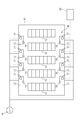
- FIG. 1 is a configuration diagram schematically showing an air conditioning system according to a first embodiment of the present invention.
- the air conditioning system 10 includes a plurality of air conditioners 12 installed in one room 11.
- the room 11 is, for example, a data center in which a large number of computer devices such as server computers and network devices are installed, and a plurality of racks 13 for installing computer devices are provided in the room.
- the plurality of air conditioners 12 are distributed in the room 11 so as to efficiently suppress the temperature rise in the room due to the heat generated by the computer equipment installed in each rack 13.
- the plurality of air conditioners 12 are supplied with power from a common commercial power supply 14.
- FIG. 2 is a diagram showing a refrigerant circuit of the air conditioner.
- the air conditioner 12 includes a heat pump refrigerant circuit 16.
- the refrigerant circuit 16 includes a compressor 17 that compresses the refrigerant to generate a high-temperature and high-pressure gas refrigerant, an outdoor heat exchanger 18 that acts as a condenser during cooling operation, and an electromagnetic expansion valve (expansion means) that depressurizes the refrigerant. 19, an indoor heat exchanger 20 that functions as an evaporator during cooling operation, and a refrigerant pipe 21 that sequentially connects them.
- the outdoor heat exchanger 18 and the indoor heat exchanger 20 are respectively provided with blower fans 22a and 22b so as to face the outdoor heat exchanger 18 and the indoor heat exchanger 20, respectively.
- the refrigerant pipe 21 is provided with a four-way switching valve (switching means) 24.
- switching means switching means
- the refrigerant flow is reversed, and the refrigerant discharged from the compressor 17 is transferred to the outdoor heat exchanger 18. It is possible to switch between the cooling operation and the heating operation by switching and supplying to the indoor heat exchanger 20.
- the refrigerant is caused to flow in the direction indicated by the solid arrow by switching the four-way switching valve 24 as shown by the solid line, the refrigerant discharged from the compressor 17 is supplied to the outdoor heat exchanger 18, and the expansion valve The refrigerant that has passed through 19 is supplied to the indoor heat exchanger 20.
- the outdoor heat exchanger 18 acts as a condenser to condense and liquefy the high-temperature and high-pressure gaseous refrigerant
- the indoor heat exchanger 20 acts as an evaporator to evaporate and vaporize the low-temperature and low-pressure liquid refrigerant. Let And it cools by sending the air cooled by exchanging heat with the indoor side heat exchanger 20 into the inside of the room 11.
- the four-way switching valve 24 is switched as indicated by a dotted line to reverse the refrigerant flow, and the refrigerant is caused to flow in the direction indicated by the dotted arrow, thereby causing the indoor heat exchanger 20 to act as a condenser.
- the outdoor heat exchanger 18 acts as an evaporator. And it heats by sending the air warmed by exchanging heat with the indoor side heat exchanger 20 into the inside of the room 11.
- the four-way switching valve 24 can be omitted, and the flow of the refrigerant can be fixed in one direction.
- the expansion valve 19, the four-way switching valve 24, the compressor 17, and the blower fans 22 a and 22 b are controlled by a control device 27 (see FIGS. 1 and 3) in accordance with sensor switches such as on / off operation switches and temperature sensors. Is done.
- the control device 27 has a microcomputer including a CPU, a memory such as a RAM, a ROM, etc., and various functions are realized by the CPU executing a program stored in the memory.
- the air conditioner 12 includes a temperature detection sensor 29 that detects the temperature of the room, and detection information of the temperature detection sensor 29 is input to the control device 27. And the control apparatus 27 controls the air conditioner 12 whole based on the various input information etc. which contain the detection information of the temperature detection sensor 29.
- the control device 27 of the present embodiment automatically turns off the air conditioner 12 when the power is restored (recovered) after the power supply to the air conditioner 12 is interrupted due to a power failure. By starting (restarting), it returns to the operation state before the power failure and has a function of suppressing the temperature rise of the room 11. Hereinafter, this function will be described in detail.
- the control device 27 of the present embodiment has a function (start timing setting function) that appropriately sets the start timing of its own air conditioner 12 so that the start timing does not overlap with other air conditioners 12. ing.
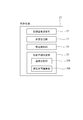
- FIG. 3 is a block diagram showing the configuration of the control device.
- the control device 27 includes an air conditioning temperature setting unit 32, a temperature storage unit 33, a power recovery detection unit 34, and a start timing setting unit 35 in order to realize the above-described start timing setting function.
- the air conditioning temperature setting unit 32 has a function of setting a target temperature (set temperature) of the room 11 via an operation unit (remote controller) (not shown) (a function of receiving settings and storing them in the temperature storage unit 33).
- the temperature storage unit 33 has a function of storing the set temperature set by the air conditioning temperature setting unit 32 and the temperature detected by the temperature detection sensor 29.
- the power recovery detection unit 34 has a function of detecting that the power supply has been restored after a power failure. Specifically, when the air conditioner 12 stops, the power recovery detection unit 34 determines whether the stop is due to a power failure, and if it is determined that the stop is due to a power failure, It is determined that the power source that was turned on is a power recovery after a power failure. For example, the power recovery detection unit 34 constantly monitors whether or not the compressor 17 of the air conditioner 12 is operating. If the compressor 17 is operating, the state (compressor on) is stored in the memory. Record. When the power is turned on after the air conditioner 12 is stopped, the power recovery detection unit 34 reads the state of the compressor 17 recorded in the memory, and when the state is the compressor on. Therefore, it can be determined that the air conditioner 12 has been abnormally stopped due to a power failure and the power has been turned on by the subsequent power recovery.
- the start time setting unit 35 sets the start time of the air conditioner 12 when power recovery after a power failure is detected by the power recovery detection unit 34.
- the start timing setting unit 35 includes a temperature comparison unit 35A and a delay time calculation unit 35B.
- the temperature comparison unit 35A compares the set temperature stored in the temperature storage unit 33 with the indoor temperature detected by the temperature detection sensor 29 after power recovery and stored in the temperature storage unit 33, and calculates the temperature difference between the two. Ask. As this temperature difference increases, the air conditioning load increases and the air conditioner 12 needs to be started quickly.
- “the temperature difference increases” means that the room temperature increases to the plus side with respect to the set temperature during the cooling operation, and the room temperature increases to the minus side with respect to the set temperature during the heating operation. That means.
- the delay time calculation unit 35B obtains a delay time until the operation of the air conditioner 12 starts (the compressor 17 starts) after power recovery based on the temperature difference between the set temperature and the room temperature.
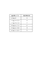
- the memory of the control device 27 stores a table used for setting the delay time as shown in FIG. In this table, a temperature difference ⁇ t between the set temperature and the room temperature and a delay time are stored in association with each other.
- the delay time is 0 second, and the temperature difference ⁇ t exceeds 2.0 ° C. or less and exceeds 1.6 ° C.
- the delay time is 1 second, and the delay time increases by 1 second each time the temperature difference ⁇ t decreases by 0.4 ° C.
- the air conditioning system 10 can be configured inexpensively and simply.
- FIG. 5 shows an example in which the starting order of a plurality of air conditioners 12 is obtained using the table shown in FIG.
- no. 1 to No. For the four air conditioners 12 of No. 4, the room temperature t 2 during the cooling operation was detected, and the starting order was determined based on the temperature difference ⁇ t from the set temperature t 1 .
- No. 1 to No. The set temperatures t 1 of the four air conditioners 12 are the same at 27.0 ° C.
- the room temperature t 2 after the power recovery is 27.2 ° C., 27.9 ° C., 28.5 ° C., and 27.5 ° C., respectively, and the temperature difference ⁇ t from the set temperature t 1 is 0.2 ° C., It becomes 0.9 degreeC, 1.5 degreeC, and 0.5 degreeC.
- each delay time is calculated
- the table shown in FIG. 4 is merely an example, and the numerical range and delay time of the temperature difference ⁇ t can be appropriately set according to the use environment of the air conditioner 12 and the like.
- the entire temperature difference ⁇ t is set so that this does not occur. It is possible to make the range wider or to set the temperature division within the entire set range more finely.
- the entire setting range of the temperature difference ⁇ t could be expanded from 0 ° C to 2 ° C to 0 ° C to 10 ° C, and the division within the entire setting range was set in increments of 0.4 ° C. Can be made finer in increments of 0.2 ° C.
- the delay time can be obtained by an arithmetic expression using the temperature difference ⁇ t as a coefficient without using the table as shown in FIG.
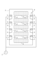
- FIG. 6 is a schematic configuration diagram of an air-conditioning system according to the second embodiment of the present invention.
- the air conditioning system 10 of the present embodiment is provided with a centralized control device 36, and this centralized control device 36 is communicably connected to the control device 27 of each air conditioner 12.
- the centralized control device 36 has the start time setting function described in the first embodiment.
- FIG. 7 is a block diagram showing a functional configuration of the centralized control device 36. Similar to the control device 27 of the first embodiment, the centralized control device 36 includes a temperature storage unit 33, a power recovery detection unit 34, and a start timing setting unit 35. This is almost the same as the embodiment. Moreover, the air-conditioning temperature setting part 32 (refer FIG. 3) demonstrated in 1st Embodiment is provided as a function of the control apparatus 27 of each air conditioner 12 also in this Embodiment. However, the air conditioning temperature setting unit 32 may be provided as a function of the central control device 36.
- the central control device 36 is connected to an uninterruptible power supply device or a private power generation device, and is configured so that the supply of electric power is not cut off even if a power failure occurs.
- the set temperature set in the air conditioning temperature setting unit 32 of each air conditioner 12 is input to the temperature storage unit 33 via the communication unit 37 and stored.
- the room temperature detected by the temperature detection sensor 29 of each air conditioner 12 is also input and stored via the communication unit 37.
- the temperature comparison unit 35A determines the difference between the set temperature and the room temperature
- the delay time calculation unit 35B determines the delay time based on the temperature difference.
- the same operational effects as in the first embodiment described above are obtained.
- the start timing of each air conditioner 12 is centrally managed in the central control device 36, for example, a delay time is obtained.
- the centralized control device 36 may include an adjustment unit 35C (see FIG. 7) that performs adjustment so that the overlapping start times are shifted from each other.
- FIG. 8 is a schematic configuration diagram of an air-conditioning system according to the third embodiment of the present invention.
- the temperature detection sensor 29 used for setting the start timing is provided not in each air conditioner 12 but in the room 11, for example, at a position closer to the rack 13 or the like. Yes.
- the plurality of temperature detection sensors 29 are respectively provided in regions affected by air conditioning by the air conditioner 12, that is, in the range of the air conditioning region corresponding to each air conditioner 12.
- Each temperature detection sensor 29 is connected to the control device 27 of the air conditioner 12 via a communication line (not shown), and the detected room temperature is input to the control device 27 and stored.
- the temperature detection sensor 29 is located near a computer device that is a heating element, and is installed in a place where the temperature change is significant. Therefore, the temperature distribution (temperature unevenness) in the room can be grasped more accurately and efficiently. A good starting time can be set. Also in the present embodiment, the central control device 36 may be provided as in the second embodiment, and the start time of the air conditioner 12 may be set by the central control device 36.
- the room temperature compared with the set temperature by the temperature comparison unit 35A of the start timing setting unit 35 is the room temperature when power is restored, but is the room temperature immediately before the power failure. be able to.
- the fact that the difference between the room temperature immediately before the power failure and the set temperature is large means that the air conditioner 12 has been operated with a high capacity until immediately before the power failure, and air conditioning in the air conditioning area corresponding to the air conditioner 12 is performed. It can be said that the load was high. Therefore, for such an air-conditioning region, the air-conditioning capability can be quickly increased by quickly starting the air conditioner 12 after power is restored.
- the air conditioning system is installed in the data center.
- the present invention is not limited to this.
- the plurality of air conditioners are not limited to one room, and may be installed in a plurality of rooms.
- Air conditioning system 12 Air conditioner 14: Commercial power supply 27: Control apparatus 29: Temperature detection sensor 32: Air-conditioning temperature setting part 33: Temperature memory
Abstract
An air conditioning system (10) comprises: a plurality of air conditioners (12) which are supplied with power from the same power source (14); temperature detection sensors (29) for detecting the room temperature in air-conditioning regions corresponding to the air conditioners (12); a temperature storage section (33) for storing set temperatures for the plurality of air conditioners (12) and the room temperatures detected by the temperature detection sensors (29); a power return detection section (34) for detecting the return of power after power stoppage; and a start-up time period setting section (35) which, if power return is detected by the power return detection section (34), compares the room temperatures that have been detected by the temperature detection sensors (29) after power return or before power stoppage and stored in the temperature storage section (33) and the set temperatures stored in the temperature storage section (33) for each of the plurality of air conditioners (12), and sets the start-up time period of the air conditioners (12) to be as early as the air conditioners (12) corresponding to air-conditioning regions having a large air conditioning load based on the difference between the compared temperatures.
Description
本発明は、空気調和システム及びその始動制御方法に関する。
The present invention relates to an air conditioning system and a start control method thereof.
サーバーコンピュータ等のコンピュータ機器を多数収容しているデータセンターでは、コンピュータ機器からの発熱による室温上昇を防止するために空調設備が完備されている。例えば、データセンター内には、コンピュータ機器を設置するための複数のラックが室内に並設され、このラックの配置や熱の流れ等に応じて複数台の空気調和機が分散して設置されている。
In a data center that houses a large number of computer equipment such as server computers, air-conditioning equipment is fully equipped to prevent room temperature from rising due to heat generated by computer equipment. For example, in a data center, a plurality of racks for installing computer equipment are juxtaposed in a room, and a plurality of air conditioners are distributed and installed in accordance with the layout of the racks and the flow of heat. Yes.
このようなデータセンターにおいて停電が発生した場合、コンピュータ機器は無停電電源装置や自家発電装置によって運転が維持されるが、空気調和機については通常電力が遮断されるので室内の温度が急激に上昇する。そのため、停電から復旧した後、空気調和機を自動的に再起動して早急に室内を冷却することが行われている。
When a power outage occurs in such a data center, the computer equipment is kept in operation by an uninterruptible power supply or a private power generator, but the air conditioner is normally powered off, so the indoor temperature rises rapidly. To do. Therefore, after recovering from a power failure, the air conditioner is automatically restarted to quickly cool the room.
しかしながら、複数台の空気調和機を同時に再起動するとピーク電流が急激に高まるため、電源設備に負荷が集中してしまうという不都合がある。そのため、従来は、複数台の空気調和機の始動順序を予め設定しておき、停電後、復電したときにはその順序にしたがって複数の空気調和機を1台ずつ始動させていた。
However, when multiple air conditioners are restarted at the same time, the peak current increases rapidly, and there is a disadvantage that the load is concentrated on the power supply equipment. Therefore, conventionally, the start order of the plurality of air conditioners is set in advance, and when the power is restored after a power failure, the plurality of air conditioners are started one by one according to the order.
なお、以下の特許文献1には、復電時の始動制御とは異なるが、複数の空気調和機を含む冷暖房システムにおいて複数の空気調和機の始動開始時刻をずらす技術が開示されている。
The following Patent Document 1 discloses a technique for shifting the start start times of a plurality of air conditioners in an air conditioning system including a plurality of air conditioners, which is different from the start control at the time of power recovery.
データセンターに並設された複数のラックには、均等にコンピュータ機器が配置されているとは限らず、特定のラックに集中してコンピュータ機器が配置されている場合がある。この場合、コンピュータ機器が集中している室内の特定領域で温度上昇が顕著となり、室内の温度分布に偏りが生じる。そのため、停電後、復電したときに予め設定された順番で空気調和機を始動すると、温度の上昇が顕著な特定領域を迅速に効率よく冷却することができない場合がある。
The computer equipment is not necessarily evenly arranged in the plurality of racks arranged in parallel in the data center, and there are cases where the computer equipment is concentrated in a specific rack. In this case, the temperature rise becomes remarkable in a specific area in the room where computer devices are concentrated, and the temperature distribution in the room is biased. Therefore, if the air conditioner is started in a preset order when power is restored after a power failure, the specific area where the temperature rise is remarkable may not be cooled quickly and efficiently.
本発明は、上記のような実情に鑑みてなされたものであり、停電後、復電したときに効率よく室温制御を行うことができる空気調和システム及びその始動制御方法を提供することとを目的とする。
The present invention has been made in view of the above circumstances, and an object thereof is to provide an air conditioning system capable of efficiently performing room temperature control when power is restored after a power failure, and a start control method thereof. And
本発明の第1の観点に係る空気調和システムは、
同一の電源から電力が供給される複数の空気調和機を備えた空気調和システムにおいて、
前記各空気調和機に対応する空調領域における室内温度をそれぞれ検出する温度検出センサと、
前記複数の空気調和機の各設定温度、及び前記温度検出センサにより検出された各室内温度を記憶する温度記憶部と、
停電後、復電したことを検知する復電検知部と、
前記復電検知部によって復電が検知された場合に、複数の空気調和機毎に前記温度記憶部に記憶された前記設定温度と復電後又は停電前に前記温度検出センサによって検出されかつ前記温度記憶部に記憶された前記室内温度とを比較し、両者の差に基づく空調負荷が大きい空調領域に対応する空気調和機ほど早期に始動させるように各空気調和機の始動時期を設定する始動時期設定部と、を備えていることを特徴とする。 An air conditioning system according to a first aspect of the present invention includes:
In an air conditioning system including a plurality of air conditioners that are supplied with power from the same power source,
A temperature detection sensor for detecting an indoor temperature in an air-conditioning region corresponding to each air conditioner;
A temperature storage unit for storing each set temperature of the plurality of air conditioners and each indoor temperature detected by the temperature detection sensor;
A power recovery detection unit that detects power recovery after a power failure,
When power recovery is detected by the power recovery detection unit, the temperature detection sensor detects the set temperature stored in the temperature storage unit for each of a plurality of air conditioners and is detected by the temperature detection sensor after power recovery or before power failure. Start by setting the start time of each air conditioner so that the air conditioner corresponding to the air-conditioning region having a large air-conditioning load based on the difference between the indoor temperatures stored in the temperature storage unit is started earlier. And a time setting unit.
本発明の空気調和システムによれば、停電後、復電した場合に、設定温度と室内温度との差に基づく空調負荷の大きい空調領域に対応する空気調和機を迅速に始動させることができ、当該空調領域の温度制御を効率よく行うことができる。
なお、本発明の空気調和機は、1台に対して1又は複数系統の冷媒回路を構成する1又は複数の圧縮機を備えたものとする。例えば、共通の圧縮機によって複数台の室内機が運転される場合には、これら複数台の室内機は1台の空気調和機を構成するものとなる。 According to the air conditioning system of the present invention, when power is restored after a power failure, the air conditioner corresponding to an air conditioning region having a large air conditioning load based on the difference between the set temperature and the room temperature can be quickly started. The temperature control of the air-conditioning area can be performed efficiently.
In addition, the air conditioner of this invention shall be equipped with the 1 or several compressor which comprises the refrigerant circuit of 1 or several systems with respect to 1 unit | set. For example, when a plurality of indoor units are operated by a common compressor, the plurality of indoor units constitute one air conditioner.
前記温度検出センサは、前記空気調和機に一体的に備わっていてもよい。
この場合、空気調和機に予め備わっている温度検出センサを、復電後の空気調和機の始動時期の設定に利用することができる。 The temperature detection sensor may be provided integrally with the air conditioner.
In this case, the temperature detection sensor provided in advance in the air conditioner can be used for setting the start time of the air conditioner after power recovery.
前記温度検出センサは、前記各空気調和機に対応する空調領域に対して当該空気調和機とは別体として備わっていてもよい。
この場合、室内に設置された発熱体の周辺など、温度変化が顕著な場所に対応して温度検出センサを設けることができ、より効率的な始動順序の設定を行うことができる。 The temperature detection sensor may be provided separately from the air conditioner with respect to the air-conditioning region corresponding to each air conditioner.
In this case, a temperature detection sensor can be provided corresponding to a place where the temperature change is remarkable, such as around a heating element installed indoors, and a more efficient starting sequence can be set.
前記複数の空気調和機のそれぞれに、前記復電検知部、前記温度記憶部、及び前記始動時期設定部が備わっていてもよい。
この構成によれば、各空気調和機がそれぞれ自立して始動時期を適切に設定することができる。そのため、空気調和機相互の始動時期の調整を行う機器を設ける必要が無く、空気調和システムを安価かつ簡素に構成することができる。 Each of the plurality of air conditioners may include the power recovery detection unit, the temperature storage unit, and the start timing setting unit.
According to this configuration, each air conditioner can independently set the start time appropriately. Therefore, it is not necessary to provide a device for adjusting the start timing of the air conditioners, and the air conditioning system can be configured inexpensively and simply.
空気調和システムは、前記復電検知部、前記温度記憶部、及び前記始動時期設定部を有している集中制御装置を更に備え、この集中制御装置と、前記各空気調和機とが通信可能に接続されていてもよい。
このような構成によって、例えば、集中制御装置が各空気調和機の始動時期を相互に調整し、始動時期が重ならないように設定するような制御が実現可能となる。 The air conditioning system further includes a central control device having the power recovery detection unit, the temperature storage unit, and the start timing setting unit, so that the central control device and each of the air conditioners can communicate with each other. It may be connected.
With such a configuration, for example, it is possible to realize control in which the central control device mutually adjusts the start times of the air conditioners and sets the start times so as not to overlap.
本発明の第2の観点に係る空気調和システムの始動制御方法は、
同一の電源から電力が供給される複数の空気調和機を備えている空気調和システムにおいて、
停電後、復電した場合に各空気調和機の設定温度と各空気調和機に対応する空調領域における復電後又は停電前の室内温度とを比較し、両者の差に基づく空調負荷が大きい空調領域に対応する空気調和機ほど早期に始動させることを特徴とする。 A start control method for an air conditioning system according to a second aspect of the present invention includes:
In an air conditioning system including a plurality of air conditioners to which power is supplied from the same power source,
Air conditioning with a large air conditioning load based on the difference between the set temperature of each air conditioner and the room temperature after power restoration or before power failure in the air conditioning area corresponding to each air conditioner when power is restored after a power failure The air conditioner corresponding to the region is started earlier.
このような構成によって、停電後、復電したときに、設定温度と室内温度との差が大きい空調領域に対応する空気調和機を迅速に始動させることができ、当該空調領域の温度制御を効率よく行うことができる。
With such a configuration, when power is restored after a power failure, the air conditioner corresponding to the air conditioning area where the difference between the set temperature and the room temperature is large can be quickly started, and the temperature control of the air conditioning area can be efficiently performed. Can be done well.
本発明によれば、停電後、復電したときに効率的な室温制御を実行することができる。
According to the present invention, efficient room temperature control can be performed when power is restored after a power failure.
[第1の実施の形態]
以下、本発明の実施の形態を図面を参照して説明する。
図1は、本発明の第1の実施の形態に係る空気調和システムを概略的に示す構成図である。空気調和システム10は、1つの部屋11に設置された複数台の空気調和機12を備えている。この部屋11は、例えば、サーバーコンピュータやネットワーク機器等の多数のコンピュータ機器を設置したデータセンターとされ、室内には、コンピュータ機器を設置するための複数のラック13が併設されている。また、複数台の空気調和機12は、各ラック13に設置されたコンピュータ機器の発熱による室内の温度上昇を効率的に抑制するように、部屋11内に分散して配置されている。また、複数の空気調和機12は、共通の商用電源14から電力が供給されている。 [First Embodiment]
Hereinafter, embodiments of the present invention will be described with reference to the drawings.
FIG. 1 is a configuration diagram schematically showing an air conditioning system according to a first embodiment of the present invention. Theair conditioning system 10 includes a plurality of air conditioners 12 installed in one room 11. The room 11 is, for example, a data center in which a large number of computer devices such as server computers and network devices are installed, and a plurality of racks 13 for installing computer devices are provided in the room. The plurality of air conditioners 12 are distributed in the room 11 so as to efficiently suppress the temperature rise in the room due to the heat generated by the computer equipment installed in each rack 13. The plurality of air conditioners 12 are supplied with power from a common commercial power supply 14.
以下、本発明の実施の形態を図面を参照して説明する。
図1は、本発明の第1の実施の形態に係る空気調和システムを概略的に示す構成図である。空気調和システム10は、1つの部屋11に設置された複数台の空気調和機12を備えている。この部屋11は、例えば、サーバーコンピュータやネットワーク機器等の多数のコンピュータ機器を設置したデータセンターとされ、室内には、コンピュータ機器を設置するための複数のラック13が併設されている。また、複数台の空気調和機12は、各ラック13に設置されたコンピュータ機器の発熱による室内の温度上昇を効率的に抑制するように、部屋11内に分散して配置されている。また、複数の空気調和機12は、共通の商用電源14から電力が供給されている。 [First Embodiment]
Hereinafter, embodiments of the present invention will be described with reference to the drawings.
FIG. 1 is a configuration diagram schematically showing an air conditioning system according to a first embodiment of the present invention. The
図2は、空気調和機の冷媒回路を示す図である。空気調和機12は、ヒートポンプ式の冷媒回路16を備えている。冷媒回路16は、冷媒を圧縮して高温高圧のガス冷媒を生成する圧縮機17と、冷房運転時に凝縮器として作用する室外側熱交換器18と、冷媒を減圧する電磁膨張弁(膨張手段)19と、冷房運転時に蒸発器として作用する室内側熱交換器20と、これらを順次接続する冷媒配管21とを備えている。また、室外側熱交換器18と室内側熱交換器20には、それぞれ送風ファン22a,22bが当該室外側熱交換器18及び室内側熱交換器20と対向して設けられている。
FIG. 2 is a diagram showing a refrigerant circuit of the air conditioner. The air conditioner 12 includes a heat pump refrigerant circuit 16. The refrigerant circuit 16 includes a compressor 17 that compresses the refrigerant to generate a high-temperature and high-pressure gas refrigerant, an outdoor heat exchanger 18 that acts as a condenser during cooling operation, and an electromagnetic expansion valve (expansion means) that depressurizes the refrigerant. 19, an indoor heat exchanger 20 that functions as an evaporator during cooling operation, and a refrigerant pipe 21 that sequentially connects them. The outdoor heat exchanger 18 and the indoor heat exchanger 20 are respectively provided with blower fans 22a and 22b so as to face the outdoor heat exchanger 18 and the indoor heat exchanger 20, respectively.
冷媒配管21には四路切換弁(切換手段)24が設けられ、この四路切換弁24を切り換えることによって冷媒の流れを反転させ、圧縮機17から吐出される冷媒を室外側熱交換器18と室内側熱交換器20とに切り換えて供給し、冷房運転と暖房運転とを切り換えることが可能となっている。
The refrigerant pipe 21 is provided with a four-way switching valve (switching means) 24. By switching the four-way switching valve 24, the refrigerant flow is reversed, and the refrigerant discharged from the compressor 17 is transferred to the outdoor heat exchanger 18. It is possible to switch between the cooling operation and the heating operation by switching and supplying to the indoor heat exchanger 20.
すなわち、冷房運転時には、四路切換弁24を実線のように切り換えることによって冷媒を実線矢印で示す方向に流し、圧縮機17から吐出された冷媒を室外側熱交換器18に供給し、膨張弁19を通過した冷媒を室内側熱交換器20に供給する。これにより、室外側熱交換器18を凝縮器として作用させて高温高圧のガス状冷媒を凝縮・液化し、室内側熱交換器20を蒸発器として作用させて低温低圧の液状冷媒を蒸発・気化させる。そして、室内側熱交換器20と熱交換することによって冷やされた空気を部屋11の内部に送り込むことによって冷房を行う。
That is, during cooling operation, the refrigerant is caused to flow in the direction indicated by the solid arrow by switching the four-way switching valve 24 as shown by the solid line, the refrigerant discharged from the compressor 17 is supplied to the outdoor heat exchanger 18, and the expansion valve The refrigerant that has passed through 19 is supplied to the indoor heat exchanger 20. As a result, the outdoor heat exchanger 18 acts as a condenser to condense and liquefy the high-temperature and high-pressure gaseous refrigerant, and the indoor heat exchanger 20 acts as an evaporator to evaporate and vaporize the low-temperature and low-pressure liquid refrigerant. Let And it cools by sending the air cooled by exchanging heat with the indoor side heat exchanger 20 into the inside of the room 11.
また、暖房運転時には、四路切換弁24を点線のように切り換えることによって、冷媒の流れを反転させ、点線矢印で示す方向に冷媒を流すことによって室内側熱交換器20を凝縮器として作用させ、室外側熱交換器18を蒸発器として作用させる。そして、室内側熱交換器20と熱交換することによって暖められた空気を部屋11の内部に送り込むことによって暖房を行う。なお、空気調和機12によって冷房又は暖房のみを行う場合には、四路切換弁24を省略し、冷媒の流れを一方向に固定することができる。
Further, during heating operation, the four-way switching valve 24 is switched as indicated by a dotted line to reverse the refrigerant flow, and the refrigerant is caused to flow in the direction indicated by the dotted arrow, thereby causing the indoor heat exchanger 20 to act as a condenser. The outdoor heat exchanger 18 acts as an evaporator. And it heats by sending the air warmed by exchanging heat with the indoor side heat exchanger 20 into the inside of the room 11. In addition, when only cooling or heating is performed by the air conditioner 12, the four-way switching valve 24 can be omitted, and the flow of the refrigerant can be fixed in one direction.
膨張弁19、四路切換弁24、圧縮機17、及び送風ファン22a,22bは、操作スイッチのオンオフや温度センサ等のセンサ出力に応じて制御装置27(図1,図3参照)により動作制御される。制御装置27は、CPUや、RAM、ROM等のメモリを備えたマイクロコンピュータを有しており、メモリに記憶されたプログラムをCPUが実行することによって各種機能を実現する。
The expansion valve 19, the four-way switching valve 24, the compressor 17, and the blower fans 22 a and 22 b are controlled by a control device 27 (see FIGS. 1 and 3) in accordance with sensor switches such as on / off operation switches and temperature sensors. Is done. The control device 27 has a microcomputer including a CPU, a memory such as a RAM, a ROM, etc., and various functions are realized by the CPU executing a program stored in the memory.
また、図1に示すように、空気調和機12は、室内の温度を検出する温度検出センサ29を備えており、この温度検出センサ29の検出情報は制御装置27に入力される。そして、制御装置27は、温度検出センサ29の検出情報を含む各種入力情報等に基づいて空気調和機12全体を制御する。
Further, as shown in FIG. 1, the air conditioner 12 includes a temperature detection sensor 29 that detects the temperature of the room, and detection information of the temperature detection sensor 29 is input to the control device 27. And the control apparatus 27 controls the air conditioner 12 whole based on the various input information etc. which contain the detection information of the temperature detection sensor 29. FIG.
本実施の形態の制御装置27は、停電が発生することによって空気調和機12への電力の供給が遮断された後、電源が復旧(復電)したときに、自動的に空気調和機12を始動(再起動)することによって停電前の運転状態に戻し、部屋11の温度上昇を抑制する機能を有している。以下、この機能について詳細に説明する。
The control device 27 of the present embodiment automatically turns off the air conditioner 12 when the power is restored (recovered) after the power supply to the air conditioner 12 is interrupted due to a power failure. By starting (restarting), it returns to the operation state before the power failure and has a function of suppressing the temperature rise of the room 11. Hereinafter, this function will be described in detail.
停電後、復電したときに複数の空気調和機12が同時に始動すると、ピーク電流が増大して電源設備に対する負荷が集中し、遮断器が作動するおそれがある。そのため、本実施の形態の制御装置27は、他の空気調和機12と始動時期が重ならないように自身の空気調和機12の始動時期を適切に設定する機能(始動時期設定機能)を有している。
If a plurality of air conditioners 12 are started simultaneously when power is restored after a power failure, the peak current increases, the load on the power supply equipment concentrates, and the circuit breaker may operate. Therefore, the control device 27 of the present embodiment has a function (start timing setting function) that appropriately sets the start timing of its own air conditioner 12 so that the start timing does not overlap with other air conditioners 12. ing.
図3は、制御装置の構成を示すブロック図である。制御装置27は、上述の始動時期設定機能を実現するために、空調温度設定部32、温度記憶部33、復電検知部34、及び始動時期設定部35を備えている。空調温度設定部32は、部屋11の目標温度(設定温度)を図示しない操作部(リモートコントローラ)を介して設定する機能(設定を受け付けて温度記憶部33に記憶させる機能)を有している。温度記憶部33は、空調温度設定部32において設定された設定温度や、温度検出センサ29によって検出された温度を記憶する機能を有する。
FIG. 3 is a block diagram showing the configuration of the control device. The control device 27 includes an air conditioning temperature setting unit 32, a temperature storage unit 33, a power recovery detection unit 34, and a start timing setting unit 35 in order to realize the above-described start timing setting function. The air conditioning temperature setting unit 32 has a function of setting a target temperature (set temperature) of the room 11 via an operation unit (remote controller) (not shown) (a function of receiving settings and storing them in the temperature storage unit 33). . The temperature storage unit 33 has a function of storing the set temperature set by the air conditioning temperature setting unit 32 and the temperature detected by the temperature detection sensor 29.
復電検知部34は、停電後、電源が復旧したことを検知する機能を有している。具体的に、復電検知部34は、空気調和機12が停止したときに、その停止が停電によるものであるか否かを判断し、停電による停止であると判断した場合には、その後に投入された電源を停電後の復電であると判断する。例えば、復電検知部34は、空気調和機12の圧縮機17が作動しているか否かを常時監視し、圧縮機17が作動している場合にはその状態(圧縮機オン)をメモリに記録する。そして、空気調和機12が停止した後電源が投入されたときに、復電検知部34は、メモリに記録されている圧縮機17の状態を読み出し、その状態が圧縮機オンである場合には、空気調和機12が停電により異常停止し、かつその後の復電によって電源が投入されたと判断することができる。
The power recovery detection unit 34 has a function of detecting that the power supply has been restored after a power failure. Specifically, when the air conditioner 12 stops, the power recovery detection unit 34 determines whether the stop is due to a power failure, and if it is determined that the stop is due to a power failure, It is determined that the power source that was turned on is a power recovery after a power failure. For example, the power recovery detection unit 34 constantly monitors whether or not the compressor 17 of the air conditioner 12 is operating. If the compressor 17 is operating, the state (compressor on) is stored in the memory. Record. When the power is turned on after the air conditioner 12 is stopped, the power recovery detection unit 34 reads the state of the compressor 17 recorded in the memory, and when the state is the compressor on. Therefore, it can be determined that the air conditioner 12 has been abnormally stopped due to a power failure and the power has been turned on by the subsequent power recovery.
始動時期設定部35は、復電検知部34によって停電後の復電が検知された場合に、空気調和機12の始動時期を設定する。具体的に、始動時期設定部35は、温度比較部35Aと、遅延時間演算部35Bとを有している。温度比較部35Aは、温度記憶部33に記憶されている設定温度と、復電後に温度検出センサ29によって検出され、温度記憶部33に記憶された室内温度とを比較し、両者の温度差を求める。この温度差が大きくなるほど空調負荷が大きくなり、空気調和機12の迅速な始動が必要となる。なお、ここで「温度差が大きくなる」とは、冷房運転時には設定温度に対して室内温度がプラス側に大きくなることをいい、暖房運転時には設定温度に対して室内温度がマイナス側に大きくなることをいう。
The start time setting unit 35 sets the start time of the air conditioner 12 when power recovery after a power failure is detected by the power recovery detection unit 34. Specifically, the start timing setting unit 35 includes a temperature comparison unit 35A and a delay time calculation unit 35B. The temperature comparison unit 35A compares the set temperature stored in the temperature storage unit 33 with the indoor temperature detected by the temperature detection sensor 29 after power recovery and stored in the temperature storage unit 33, and calculates the temperature difference between the two. Ask. As this temperature difference increases, the air conditioning load increases and the air conditioner 12 needs to be started quickly. Here, “the temperature difference increases” means that the room temperature increases to the plus side with respect to the set temperature during the cooling operation, and the room temperature increases to the minus side with respect to the set temperature during the heating operation. That means.
遅延時間演算部35Bは、設定温度と室内温度との温度差に基づいて、復電後、空気調和機12の運転が始動(圧縮機17が始動)するまでの遅延時間を求める。例えば、制御装置27のメモリには、図4に示すような遅延時間の設定に使用されるテーブルが記憶されている。このテーブルには、設定温度と室内温度との温度差Δtと、遅延時間とが対応付けられた状態で記憶されている。図4の例では、設定温度と室内温度との温度差Δtが2.0℃を超える場合は、遅延時間が0秒とされ、温度差Δtが2.0℃以下1.6℃を超える場合は、遅延時間が1秒とされ、以下、温度差Δtが0.4℃小さくなるごとに遅延時間が1秒ずつ増えている。
The delay time calculation unit 35B obtains a delay time until the operation of the air conditioner 12 starts (the compressor 17 starts) after power recovery based on the temperature difference between the set temperature and the room temperature. For example, the memory of the control device 27 stores a table used for setting the delay time as shown in FIG. In this table, a temperature difference Δt between the set temperature and the room temperature and a delay time are stored in association with each other. In the example of FIG. 4, when the temperature difference Δt between the set temperature and the room temperature exceeds 2.0 ° C., the delay time is 0 second, and the temperature difference Δt exceeds 2.0 ° C. or less and exceeds 1.6 ° C. The delay time is 1 second, and the delay time increases by 1 second each time the temperature difference Δt decreases by 0.4 ° C.
したがって、設定温度と室内温度との温度差Δtが大きいほど(空調負荷が大きいほど)遅延時間は短くなり、迅速に空気調和機12が始動されることになる。したがって、部屋11の内部で、より空調が必要な領域に対して迅速な室温制御を行うことが可能となっている。
Therefore, the larger the temperature difference Δt between the set temperature and the room temperature (the greater the air conditioning load), the shorter the delay time and the quicker the air conditioner 12 is started. Therefore, it is possible to perform rapid room temperature control on an area that needs more air conditioning inside the room 11.
また、復電後の始動時期設定は、各空気調和機12の制御装置27がそれぞれ自立して実行するものであるため、始動時期設定のために各空気調和機12間の調整、管理を行うための機器が不要となり、空気調和システム10を安価かつ簡素に構成することができる。
In addition, since the start time setting after the power recovery is performed independently by the control device 27 of each air conditioner 12, adjustment and management between the air conditioners 12 are performed for the start time setting. Therefore, the air conditioning system 10 can be configured inexpensively and simply.
図5は、図4に示すテーブルを用いて複数台の空気調和機12の始動順位を求めた例を示す。ここではNo.1からNo.4の4台の空気調和機12について冷房運転時の室内温度t2を検出し、設定温度t1との温度差Δtに基づいて始動順位を求めた。No.1からNo.4の空気調和機12の設定温度t1はいずれも27.0℃で同一である。復電後の室内温度t2は、それぞれ、27.2℃、27.9℃、28.5℃、27.5℃であり、設定温度t1との温度差Δtは、0.2℃、0.9℃、1.5℃、0.5℃となる。そして、図4のテーブルを参酌することによって、それぞれの遅延時間が求められ、この遅延時間によって複数の空気調和機12の始動順位が定められることになる。
FIG. 5 shows an example in which the starting order of a plurality of air conditioners 12 is obtained using the table shown in FIG. Here, no. 1 to No. For the four air conditioners 12 of No. 4, the room temperature t 2 during the cooling operation was detected, and the starting order was determined based on the temperature difference Δt from the set temperature t 1 . No. 1 to No. The set temperatures t 1 of the four air conditioners 12 are the same at 27.0 ° C. The room temperature t 2 after the power recovery is 27.2 ° C., 27.9 ° C., 28.5 ° C., and 27.5 ° C., respectively, and the temperature difference Δt from the set temperature t 1 is 0.2 ° C., It becomes 0.9 degreeC, 1.5 degreeC, and 0.5 degreeC. And each delay time is calculated | required by referring to the table of FIG. 4, and the starting order of the some air conditioner 12 is determined by this delay time.
なお、図4に示すテーブルはあくまで例示であり、温度差Δtの数値範囲や遅延時間については空気調和機12の使用環境等に応じて適宜設定することができる。例えば、図4では、温度差Δtが2℃を超える空気調和機12が複数台ある場合、これらは同時に始動することになるが、このようなことが生じないように温度差Δtの全体の設定範囲をより広くしたり、全体の設定範囲内における温度の区分けをより細かく設定したりすることが可能である。例えば、温度差Δtの全体の設定範囲は、0℃~2℃としていたのを0℃~10℃のように広げることができ、全体の設定範囲内における区分けを0.4℃刻みとしていたのを0.2℃刻みのように細かくすることができる。また、図4のようなテーブルを用いずに、温度差Δtを係数とした演算式によって遅延時間を求めることも可能である。
Note that the table shown in FIG. 4 is merely an example, and the numerical range and delay time of the temperature difference Δt can be appropriately set according to the use environment of the air conditioner 12 and the like. For example, in FIG. 4, when there are a plurality of air conditioners 12 having a temperature difference Δt exceeding 2 ° C., these will start at the same time, but the entire temperature difference Δt is set so that this does not occur. It is possible to make the range wider or to set the temperature division within the entire set range more finely. For example, the entire setting range of the temperature difference Δt could be expanded from 0 ° C to 2 ° C to 0 ° C to 10 ° C, and the division within the entire setting range was set in increments of 0.4 ° C. Can be made finer in increments of 0.2 ° C. Further, the delay time can be obtained by an arithmetic expression using the temperature difference Δt as a coefficient without using the table as shown in FIG.
[第2の実施の形態]
図6は、本発明の第2の実施の形態に係る空気調和システムの概略構成図である。
本実施の形態の空気調和システム10には、集中制御装置36が設けられており、この集中制御装置36は、各空気調和機12の制御装置27に通信可能に接続されている。そして、第1の実施の形態で説明した始動時期設定機能が集中制御装置36に備わっている。 [Second Embodiment]
FIG. 6 is a schematic configuration diagram of an air-conditioning system according to the second embodiment of the present invention.
Theair conditioning system 10 of the present embodiment is provided with a centralized control device 36, and this centralized control device 36 is communicably connected to the control device 27 of each air conditioner 12. The centralized control device 36 has the start time setting function described in the first embodiment.
図6は、本発明の第2の実施の形態に係る空気調和システムの概略構成図である。
本実施の形態の空気調和システム10には、集中制御装置36が設けられており、この集中制御装置36は、各空気調和機12の制御装置27に通信可能に接続されている。そして、第1の実施の形態で説明した始動時期設定機能が集中制御装置36に備わっている。 [Second Embodiment]
FIG. 6 is a schematic configuration diagram of an air-conditioning system according to the second embodiment of the present invention.
The
図7は、集中制御装置36の機能構成を示すブロック図である。この集中制御装置36は、第1の実施の形態の制御装置27と同様に、温度記憶部33、復電検知部34、及び始動時期設定部35を備えており、これらの機能は、第1の実施の形態と概ね同じである。また、第1の実施の形態において説明した空調温度設定部32(図3参照)は、本実施の形態でも各空気調和機12の制御装置27の機能として備えられている。ただし、この空調温度設定部32は、集中制御装置36の機能として備えられていてもよい。
FIG. 7 is a block diagram showing a functional configuration of the centralized control device 36. Similar to the control device 27 of the first embodiment, the centralized control device 36 includes a temperature storage unit 33, a power recovery detection unit 34, and a start timing setting unit 35. This is almost the same as the embodiment. Moreover, the air-conditioning temperature setting part 32 (refer FIG. 3) demonstrated in 1st Embodiment is provided as a function of the control apparatus 27 of each air conditioner 12 also in this Embodiment. However, the air conditioning temperature setting unit 32 may be provided as a function of the central control device 36.
図7に示すように、集中制御装置36は、無停電電源装置又は自家発電装置に接続されており、停電が起きたとしても電力の供給が遮断されないように構成されている。
温度記憶部33には、各空気調和機12の空調温度設定部32において設定された設定温度が通信部37を介して入力され、記憶される。また、各空気調和機12の温度検出センサ29によって検出された室内温度も通信部37を介して入力され、記憶される。
そして、始動時期設定部35では、温度比較部35Aにおいて設定温度と室内温度との差が求められ、遅延時間演算部35Bにおいて温度差に基づいて遅延時間が求められる。 As shown in FIG. 7, thecentral control device 36 is connected to an uninterruptible power supply device or a private power generation device, and is configured so that the supply of electric power is not cut off even if a power failure occurs.
The set temperature set in the air conditioningtemperature setting unit 32 of each air conditioner 12 is input to the temperature storage unit 33 via the communication unit 37 and stored. In addition, the room temperature detected by the temperature detection sensor 29 of each air conditioner 12 is also input and stored via the communication unit 37.
In the starttiming setting unit 35, the temperature comparison unit 35A determines the difference between the set temperature and the room temperature, and the delay time calculation unit 35B determines the delay time based on the temperature difference.
温度記憶部33には、各空気調和機12の空調温度設定部32において設定された設定温度が通信部37を介して入力され、記憶される。また、各空気調和機12の温度検出センサ29によって検出された室内温度も通信部37を介して入力され、記憶される。
そして、始動時期設定部35では、温度比較部35Aにおいて設定温度と室内温度との差が求められ、遅延時間演算部35Bにおいて温度差に基づいて遅延時間が求められる。 As shown in FIG. 7, the
The set temperature set in the air conditioning
In the start
本実施の形態では、上述の第1の実施の形態と概ね同様の作用効果を奏するが、各空気調和機12における始動時期が集中制御装置36において集中管理されるため、例えば、遅延時間を求めた結果、複数台の空気調和機12の間で始動時期が重なった場合には、これらの始動時期を相互にずらすような調整(例えば、一方の始動時期を更に+0.5秒遅延させる等)を行うことが可能となる。したがって、集中制御装置36は、重複した始動時期を相互にずらすように調整を行う調整部35C(図7参照)を備えていてもよい。これにより、ピーク電流の増大を確実に抑制することができ、電源設備に対する負担をより軽減することができる。
In the present embodiment, the same operational effects as in the first embodiment described above are obtained. However, since the start timing of each air conditioner 12 is centrally managed in the central control device 36, for example, a delay time is obtained. As a result, when the start times overlap among a plurality of air conditioners 12, adjustments are made such that these start times are shifted from each other (for example, one start time is further delayed by +0.5 seconds). Can be performed. Therefore, the centralized control device 36 may include an adjustment unit 35C (see FIG. 7) that performs adjustment so that the overlapping start times are shifted from each other. Thereby, the increase in peak current can be reliably suppressed, and the burden on the power supply facility can be further reduced.
[第3の実施の形態]
図8は、本発明の第3の実施の形態に係る空気調和システムの概略構成図である。
本実施の形態の空気調和システム10は、始動時期設定のために用いられる温度検出センサ29が、各空気調和機12ではなく部屋11の内部、例えば、よりラック13に近い位置等に設けられている。複数の温度検出センサ29は、それぞれ空気調和機12による空調の影響がおよぶ領域、すなわち、各空気調和機12に対応する空調領域の範囲内にそれぞれ設けられている。また、各温度検出センサ29は、図示しない通信線を介して空気調和機12の制御装置27に接続されており、検出された室内温度が制御装置27に入力され、記憶される。 [Third Embodiment]
FIG. 8 is a schematic configuration diagram of an air-conditioning system according to the third embodiment of the present invention.
In theair conditioning system 10 of the present embodiment, the temperature detection sensor 29 used for setting the start timing is provided not in each air conditioner 12 but in the room 11, for example, at a position closer to the rack 13 or the like. Yes. The plurality of temperature detection sensors 29 are respectively provided in regions affected by air conditioning by the air conditioner 12, that is, in the range of the air conditioning region corresponding to each air conditioner 12. Each temperature detection sensor 29 is connected to the control device 27 of the air conditioner 12 via a communication line (not shown), and the detected room temperature is input to the control device 27 and stored.
図8は、本発明の第3の実施の形態に係る空気調和システムの概略構成図である。
本実施の形態の空気調和システム10は、始動時期設定のために用いられる温度検出センサ29が、各空気調和機12ではなく部屋11の内部、例えば、よりラック13に近い位置等に設けられている。複数の温度検出センサ29は、それぞれ空気調和機12による空調の影響がおよぶ領域、すなわち、各空気調和機12に対応する空調領域の範囲内にそれぞれ設けられている。また、各温度検出センサ29は、図示しない通信線を介して空気調和機12の制御装置27に接続されており、検出された室内温度が制御装置27に入力され、記憶される。 [Third Embodiment]
FIG. 8 is a schematic configuration diagram of an air-conditioning system according to the third embodiment of the present invention.
In the
本実施の形態では、温度検出センサ29は、発熱体となるコンピュータ機器により近く、温度変化が顕著となる場所に設置されるため、室内の温度分布(温度ムラ)をより正確に把握して効率のよい始動時期の設定を行うことができる。
なお、本実施の形態においても、第2の実施の形態のように集中制御装置36を設け、この集中制御装置36によって空気調和機12の始動時期の設定を行ってもよい。 In the present embodiment, thetemperature detection sensor 29 is located near a computer device that is a heating element, and is installed in a place where the temperature change is significant. Therefore, the temperature distribution (temperature unevenness) in the room can be grasped more accurately and efficiently. A good starting time can be set.
Also in the present embodiment, thecentral control device 36 may be provided as in the second embodiment, and the start time of the air conditioner 12 may be set by the central control device 36.
なお、本実施の形態においても、第2の実施の形態のように集中制御装置36を設け、この集中制御装置36によって空気調和機12の始動時期の設定を行ってもよい。 In the present embodiment, the
Also in the present embodiment, the
本発明は、上記実施の形態に限定されず、特許請求の範囲に記載された発明の範囲内において適宜変更することができる。
例えば、上記実施の形態において、始動時期設定部35の温度比較部35Aによって設定温度と比較されていた室内温度は、復電したときの室内温度とされていたが、停電直前の室内温度とすることができる。停電直前の室内温度と設定温度との差が大きいということは、その空気調和機12は停電の直前まで高い能力で運転していたことになり、その空気調和機12に対応する空調領域の空調負荷が高くなっていたといえる。したがって、このような空調領域に対しては、復電後、迅速に空気調和機12を始動させることにより、空調能力を迅速に高めることができる。 The present invention is not limited to the above-described embodiment, and can be appropriately changed within the scope of the invention described in the claims.
For example, in the above embodiment, the room temperature compared with the set temperature by thetemperature comparison unit 35A of the start timing setting unit 35 is the room temperature when power is restored, but is the room temperature immediately before the power failure. be able to. The fact that the difference between the room temperature immediately before the power failure and the set temperature is large means that the air conditioner 12 has been operated with a high capacity until immediately before the power failure, and air conditioning in the air conditioning area corresponding to the air conditioner 12 is performed. It can be said that the load was high. Therefore, for such an air-conditioning region, the air-conditioning capability can be quickly increased by quickly starting the air conditioner 12 after power is restored.
例えば、上記実施の形態において、始動時期設定部35の温度比較部35Aによって設定温度と比較されていた室内温度は、復電したときの室内温度とされていたが、停電直前の室内温度とすることができる。停電直前の室内温度と設定温度との差が大きいということは、その空気調和機12は停電の直前まで高い能力で運転していたことになり、その空気調和機12に対応する空調領域の空調負荷が高くなっていたといえる。したがって、このような空調領域に対しては、復電後、迅速に空気調和機12を始動させることにより、空調能力を迅速に高めることができる。 The present invention is not limited to the above-described embodiment, and can be appropriately changed within the scope of the invention described in the claims.
For example, in the above embodiment, the room temperature compared with the set temperature by the
上記実施の形態では、空気調和システムがデータセンターに設置されている場合について説明したが、これに限定されるものではない。また、複数台の空気調和機は、一つの部屋に限らず、複数の部屋に分散して設置されていてもよい。
In the above embodiment, the case where the air conditioning system is installed in the data center has been described. However, the present invention is not limited to this. Further, the plurality of air conditioners are not limited to one room, and may be installed in a plurality of rooms.
10: 空気調和システム
12: 空気調和機
14: 商用電源
27: 制御装置
29: 温度検出センサ
32: 空調温度設定部
33: 温度記憶部
34: 復電検知部
35: 始動時期設定部
36: 集中制御装置 DESCRIPTION OF SYMBOLS 10: Air conditioning system 12: Air conditioner 14: Commercial power supply 27: Control apparatus 29: Temperature detection sensor 32: Air-conditioning temperature setting part 33: Temperature memory | storage part 34: Power recovery detection part 35: Start time setting part 36: Centralized control apparatus
Claims (6)
- 同一の電源(14)から電力が供給される複数の空気調和機(12)を備えた空気調和システムにおいて、
前記各空気調和機(12)に対応する空調領域における室内温度をそれぞれ検出する温度検出センサ(29)と、
前記複数の空気調和機(12)の各設定温度、及び前記温度検出センサ(29)により検出された各室内温度を記憶する温度記憶部(33)と、
停電後に復電したことを検知する復電検知部(34)と、
前記復電検知部(34)によって復電が検知された場合に、複数の空気調和機(12)毎に前記温度記憶部(33)に記憶された前記設定温度と復電後又は停電前に前記温度検出センサ(29)によって検出されかつ前記温度記憶部(33)に記憶された前記室内温度とを比較し、両者の差に基づく空調負荷が大きい空調領域に対応する空気調和機(12)ほど早期に始動させるように各空気調和機(12)の始動時期を設定する始動時期設定部(35)と、を備えていることを特徴とする空気調和システム。 In an air conditioning system including a plurality of air conditioners (12) to which power is supplied from the same power source (14),
A temperature detection sensor (29) for detecting a room temperature in an air-conditioning region corresponding to each air conditioner (12);
A temperature storage unit (33) for storing each set temperature of the plurality of air conditioners (12) and each indoor temperature detected by the temperature detection sensor (29);
A power recovery detector (34) for detecting power recovery after a power failure;
When power recovery is detected by the power recovery detection unit (34), the set temperature stored in the temperature storage unit (33) for each of a plurality of air conditioners (12) and after power recovery or before power failure The air conditioner (12) corresponding to the air-conditioning region where the air-conditioning load is large based on the difference between the room temperatures detected by the temperature detection sensor (29) and stored in the temperature storage unit (33). An air conditioning system comprising: a start timing setting section (35) for setting the start timing of each air conditioner (12) so as to start as early as possible. - 前記温度検出センサ(29)が前記空気調和機(12)に一体に備わっている請求項1に記載の空気調和システム。 The air conditioning system according to claim 1, wherein the temperature detection sensor (29) is provided integrally with the air conditioner (12).
- 前記温度検出センサ(29)が、前記各空気調和機(12)に対応する空調領域に当該空気調和機(12)とは別体として備わっている請求項1に記載の空気調和システム。 The air conditioning system according to claim 1, wherein the temperature detection sensor (29) is provided separately from the air conditioner (12) in an air conditioning region corresponding to the air conditioner (12).
- 前記複数の空気調和機(12)に、それぞれ前記温度記憶部(33)、前記復電検知部(34)、及び前記始動時期設定部(35)が備わっている請求項1~3のいずれかに記載の空気調和システム。 The plurality of air conditioners (12) each include the temperature storage unit (33), the power recovery detection unit (34), and the start timing setting unit (35). Air conditioning system as described in.
- 前記温度記憶部(33)、前記復電検知部(34)、及び前記始動時期設定部(35)を有している集中制御装置(36)を更に備え、この集中制御装置(36)と、前記各空気調和機(12)とが通信可能に接続されている請求項1~3のいずれかに記載の空気調和システム。 A central control device (36) having the temperature storage unit (33), the power recovery detection unit (34), and the start timing setting unit (35), and the central control device (36); The air conditioning system according to any one of claims 1 to 3, wherein the air conditioners (12) are communicably connected.
- 同一の電源(14)から電力が供給される複数の空気調和機(12)を備えている空気調和システムにおいて、
停電後、復電した場合に、各空気調和機(12)の設定温度と各空気調和機(12)に対応する空調領域における復電後又は停電前の室内温度とを比較し、両者の差に基づく空調負荷が大きい空調領域に対応する空気調和機(12)ほど早期に始動させることを特徴とする空気調和システムの始動制御方法。 In an air conditioning system including a plurality of air conditioners (12) to which power is supplied from the same power source (14),
When power is restored after a power failure, the set temperature of each air conditioner (12) is compared with the room temperature after power restoration or before power failure in the air conditioning area corresponding to each air conditioner (12). A start control method for an air conditioning system, wherein an air conditioner (12) corresponding to an air conditioning region with a large air conditioning load is started earlier.
Priority Applications (2)
| Application Number | Priority Date | Filing Date | Title |
|---|---|---|---|
| US13/978,694 US20130291576A1 (en) | 2011-01-25 | 2011-12-06 | Air conditioning system and initiation control method of the same |
| EP11856757.7A EP2669588A1 (en) | 2011-01-25 | 2011-12-06 | Air conditioning system and start-up control method therefor |
Applications Claiming Priority (2)
| Application Number | Priority Date | Filing Date | Title |
|---|---|---|---|
| JP2011-012848 | 2011-01-25 | ||
| JP2011012848A JP5728966B2 (en) | 2011-01-25 | 2011-01-25 | Air conditioning system and start control method thereof |
Publications (1)
| Publication Number | Publication Date |
|---|---|
| WO2012101902A1 true WO2012101902A1 (en) | 2012-08-02 |
Family
ID=46580486
Family Applications (1)
| Application Number | Title | Priority Date | Filing Date |
|---|---|---|---|
| PCT/JP2011/078120 WO2012101902A1 (en) | 2011-01-25 | 2011-12-06 | Air conditioning system and start-up control method therefor |
Country Status (4)
| Country | Link |
|---|---|
| US (1) | US20130291576A1 (en) |
| EP (1) | EP2669588A1 (en) |
| JP (1) | JP5728966B2 (en) |
| WO (1) | WO2012101902A1 (en) |
Cited By (2)
| Publication number | Priority date | Publication date | Assignee | Title |
|---|---|---|---|---|
| JP2017062086A (en) * | 2015-09-25 | 2017-03-30 | トヨタ自動車株式会社 | Air Conditioning System |
| US10006725B2 (en) | 2012-02-13 | 2018-06-26 | Mitsubishi Heavy Industries Thermal Systems, Ltd. | Heat source system and method for controlling number of machines to be started at time of power recovery in heat source system |
Families Citing this family (8)
| Publication number | Priority date | Publication date | Assignee | Title |
|---|---|---|---|---|
| US8123571B2 (en) * | 2009-05-21 | 2012-02-28 | Lennox Industries Inc. | Air conditioning wiring system |
| JP6183024B2 (en) * | 2013-07-18 | 2017-08-23 | 三菱電機株式会社 | Air conditioner system |
| US10409345B2 (en) * | 2015-03-23 | 2019-09-10 | Nec Corporation | Phase change cooling device and phase change cooling method |
| JP6578920B2 (en) * | 2015-12-08 | 2019-09-25 | ダイキン工業株式会社 | Air conditioner control device |
| CN108489021A (en) * | 2018-03-12 | 2018-09-04 | 珠海格力电器股份有限公司 | A kind of implementation method, device and the air-conditioning of air-conditioning adaptive model |
| US11221156B2 (en) * | 2018-04-24 | 2022-01-11 | Johnson Controls Tyco IP Holdings LLP | Central plant control system with decaying capacity adjustment |
| CN109780687B (en) * | 2018-12-18 | 2020-04-21 | 珠海格力电器股份有限公司 | Air conditioner starting-up pre-blowing control method and system and air conditioner |
| CN110094826A (en) * | 2019-04-10 | 2019-08-06 | 深圳供电局有限公司 | A kind of Multi-zone ventilation temperature control system and method |
Citations (5)
| Publication number | Priority date | Publication date | Assignee | Title |
|---|---|---|---|---|
| JPS6210550A (en) * | 1985-07-08 | 1987-01-19 | Matsushita Refrig Co | Successive starting device of air conditioners |
| JPH0742998A (en) * | 1993-07-27 | 1995-02-10 | Matsushita Electric Works Ltd | Power source interruption controller |
| JPH07198185A (en) * | 1993-12-28 | 1995-08-01 | Sanyo Electric Co Ltd | Air conditioner |
| JP2000234787A (en) * | 1999-02-16 | 2000-08-29 | Matsushita Electric Ind Co Ltd | Operation controlling method and apparatus for air conditioning |
| JP2009162475A (en) * | 2007-12-14 | 2009-07-23 | Daikin Ind Ltd | Air conditioner |
Family Cites Families (4)
| Publication number | Priority date | Publication date | Assignee | Title |
|---|---|---|---|---|
| JPS61147080A (en) * | 1984-12-20 | 1986-07-04 | 三菱電機株式会社 | Refrigerating air-conditioning system apparatus |
| JP3789620B2 (en) * | 1997-12-09 | 2006-06-28 | 三洋電機株式会社 | Air conditioner |
| US6119469A (en) * | 1999-06-14 | 2000-09-19 | Spx Corporation | Programmable electronic start-up delay for refrigeration units |
| JP2005300016A (en) * | 2004-04-12 | 2005-10-27 | Hitachi Ltd | Air conditioning system |
-
2011
- 2011-01-25 JP JP2011012848A patent/JP5728966B2/en not_active Expired - Fee Related
- 2011-12-06 US US13/978,694 patent/US20130291576A1/en not_active Abandoned
- 2011-12-06 WO PCT/JP2011/078120 patent/WO2012101902A1/en active Application Filing
- 2011-12-06 EP EP11856757.7A patent/EP2669588A1/en not_active Withdrawn
Patent Citations (6)
| Publication number | Priority date | Publication date | Assignee | Title |
|---|---|---|---|---|
| JPS6210550A (en) * | 1985-07-08 | 1987-01-19 | Matsushita Refrig Co | Successive starting device of air conditioners |
| JPH0742998A (en) * | 1993-07-27 | 1995-02-10 | Matsushita Electric Works Ltd | Power source interruption controller |
| JPH07198185A (en) * | 1993-12-28 | 1995-08-01 | Sanyo Electric Co Ltd | Air conditioner |
| JP2994940B2 (en) | 1993-12-28 | 1999-12-27 | 三洋電機株式会社 | Air conditioner |
| JP2000234787A (en) * | 1999-02-16 | 2000-08-29 | Matsushita Electric Ind Co Ltd | Operation controlling method and apparatus for air conditioning |
| JP2009162475A (en) * | 2007-12-14 | 2009-07-23 | Daikin Ind Ltd | Air conditioner |
Cited By (2)
| Publication number | Priority date | Publication date | Assignee | Title |
|---|---|---|---|---|
| US10006725B2 (en) | 2012-02-13 | 2018-06-26 | Mitsubishi Heavy Industries Thermal Systems, Ltd. | Heat source system and method for controlling number of machines to be started at time of power recovery in heat source system |
| JP2017062086A (en) * | 2015-09-25 | 2017-03-30 | トヨタ自動車株式会社 | Air Conditioning System |
Also Published As
| Publication number | Publication date |
|---|---|
| EP2669588A1 (en) | 2013-12-04 |
| US20130291576A1 (en) | 2013-11-07 |
| JP2012154531A (en) | 2012-08-16 |
| JP5728966B2 (en) | 2015-06-03 |
Similar Documents
| Publication | Publication Date | Title |
|---|---|---|
| JP5728966B2 (en) | Air conditioning system and start control method thereof | |
| KR20130030405A (en) | Air conditioner | |
| JP5267479B2 (en) | Air conditioning apparatus and air conditioning system | |
| WO2013145844A1 (en) | Heat source system, device for controlling same, and method for controlling same | |
| US20160320113A1 (en) | Air conditioning apparatus | |
| JP2007024431A (en) | Air conditioning system, and operating method during its emergency power feeding | |
| US10359209B2 (en) | Air conditioning apparatus | |
| JP6466716B2 (en) | Air conditioner | |
| JP2014074564A (en) | Air conditioner | |
| JP2014020661A (en) | Air conditioner | |
| JP2015087064A (en) | Air conditioning system | |
| JP2001304651A (en) | Air conditioner and its operation control method | |
| JP2016133290A (en) | Refrigeration cycle device | |
| US11313572B2 (en) | Configuration management systems for heating, ventilation, and air conditioning (HVAC) systems | |
| WO2018047264A1 (en) | Refrigeration cycle device | |
| JP2007071401A (en) | Air conditioner | |
| CN113531790A (en) | Communication control circuit, multi-connected air conditioner and control method | |
| JP5954995B2 (en) | Air conditioner | |
| JP2011174686A (en) | Refrigerating machine for transportation | |
| CN104896580A (en) | Air-conditioning apparatus | |
| JP5012102B2 (en) | Vending machine control equipment | |
| JP6991338B2 (en) | Air conditioner | |
| JP6324612B2 (en) | Refrigeration cycle equipment | |
| JP5802169B2 (en) | Heat pump and operation method thereof | |
| KR101105952B1 (en) | A multi type air conditioner and method of controlling the same |
Legal Events
| Date | Code | Title | Description |
|---|---|---|---|
| 121 | Ep: the epo has been informed by wipo that ep was designated in this application |
Ref document number: 11856757 Country of ref document: EP Kind code of ref document: A1 |
|
| WWE | Wipo information: entry into national phase |
Ref document number: 13978694 Country of ref document: US |
|
| NENP | Non-entry into the national phase |
Ref country code: DE |
|
| WWE | Wipo information: entry into national phase |
Ref document number: 2011856757 Country of ref document: EP |