WO2012099191A1 - Air delivery pipe and supercharger - Google Patents
Air delivery pipe and supercharger Download PDFInfo
- Publication number
- WO2012099191A1 WO2012099191A1 PCT/JP2012/051048 JP2012051048W WO2012099191A1 WO 2012099191 A1 WO2012099191 A1 WO 2012099191A1 JP 2012051048 W JP2012051048 W JP 2012051048W WO 2012099191 A1 WO2012099191 A1 WO 2012099191A1
- Authority
- WO
- WIPO (PCT)
- Prior art keywords
- air supply
- pipe
- supply pipe
- curvature
- radius
- Prior art date
Links
Images


Classifications
-
- F—MECHANICAL ENGINEERING; LIGHTING; HEATING; WEAPONS; BLASTING
- F17—STORING OR DISTRIBUTING GASES OR LIQUIDS
- F17D—PIPE-LINE SYSTEMS; PIPE-LINES
- F17D1/00—Pipe-line systems
- F17D1/08—Pipe-line systems for liquids or viscous products
-
- F—MECHANICAL ENGINEERING; LIGHTING; HEATING; WEAPONS; BLASTING
- F16—ENGINEERING ELEMENTS AND UNITS; GENERAL MEASURES FOR PRODUCING AND MAINTAINING EFFECTIVE FUNCTIONING OF MACHINES OR INSTALLATIONS; THERMAL INSULATION IN GENERAL
- F16L—PIPES; JOINTS OR FITTINGS FOR PIPES; SUPPORTS FOR PIPES, CABLES OR PROTECTIVE TUBING; MEANS FOR THERMAL INSULATION IN GENERAL
- F16L9/00—Rigid pipes
- F16L9/006—Rigid pipes specially profiled
-
- F—MECHANICAL ENGINEERING; LIGHTING; HEATING; WEAPONS; BLASTING
- F02—COMBUSTION ENGINES; HOT-GAS OR COMBUSTION-PRODUCT ENGINE PLANTS
- F02M—SUPPLYING COMBUSTION ENGINES IN GENERAL WITH COMBUSTIBLE MIXTURES OR CONSTITUENTS THEREOF
- F02M35/00—Combustion-air cleaners, air intakes, intake silencers, or induction systems specially adapted for, or arranged on, internal-combustion engines
- F02M35/10—Air intakes; Induction systems
- F02M35/10091—Air intakes; Induction systems characterised by details of intake ducts: shapes; connections; arrangements
- F02M35/10111—Substantially V-, C- or U-shaped ducts in direction of the flow path
-
- F—MECHANICAL ENGINEERING; LIGHTING; HEATING; WEAPONS; BLASTING
- F02—COMBUSTION ENGINES; HOT-GAS OR COMBUSTION-PRODUCT ENGINE PLANTS
- F02M—SUPPLYING COMBUSTION ENGINES IN GENERAL WITH COMBUSTIBLE MIXTURES OR CONSTITUENTS THEREOF
- F02M35/00—Combustion-air cleaners, air intakes, intake silencers, or induction systems specially adapted for, or arranged on, internal-combustion engines
- F02M35/10—Air intakes; Induction systems
- F02M35/10091—Air intakes; Induction systems characterised by details of intake ducts: shapes; connections; arrangements
- F02M35/10144—Connections of intake ducts to each other or to another device
-
- F—MECHANICAL ENGINEERING; LIGHTING; HEATING; WEAPONS; BLASTING
- F02—COMBUSTION ENGINES; HOT-GAS OR COMBUSTION-PRODUCT ENGINE PLANTS
- F02M—SUPPLYING COMBUSTION ENGINES IN GENERAL WITH COMBUSTIBLE MIXTURES OR CONSTITUENTS THEREOF
- F02M35/00—Combustion-air cleaners, air intakes, intake silencers, or induction systems specially adapted for, or arranged on, internal-combustion engines
- F02M35/10—Air intakes; Induction systems
- F02M35/1015—Air intakes; Induction systems characterised by the engine type
- F02M35/10157—Supercharged engines
-
- F—MECHANICAL ENGINEERING; LIGHTING; HEATING; WEAPONS; BLASTING
- F16—ENGINEERING ELEMENTS AND UNITS; GENERAL MEASURES FOR PRODUCING AND MAINTAINING EFFECTIVE FUNCTIONING OF MACHINES OR INSTALLATIONS; THERMAL INSULATION IN GENERAL
- F16L—PIPES; JOINTS OR FITTINGS FOR PIPES; SUPPORTS FOR PIPES, CABLES OR PROTECTIVE TUBING; MEANS FOR THERMAL INSULATION IN GENERAL
- F16L43/00—Bends; Siphons
-
- F—MECHANICAL ENGINEERING; LIGHTING; HEATING; WEAPONS; BLASTING
- F02—COMBUSTION ENGINES; HOT-GAS OR COMBUSTION-PRODUCT ENGINE PLANTS
- F02B—INTERNAL-COMBUSTION PISTON ENGINES; COMBUSTION ENGINES IN GENERAL
- F02B37/00—Engines characterised by provision of pumps driven at least for part of the time by exhaust
-
- Y—GENERAL TAGGING OF NEW TECHNOLOGICAL DEVELOPMENTS; GENERAL TAGGING OF CROSS-SECTIONAL TECHNOLOGIES SPANNING OVER SEVERAL SECTIONS OF THE IPC; TECHNICAL SUBJECTS COVERED BY FORMER USPC CROSS-REFERENCE ART COLLECTIONS [XRACs] AND DIGESTS
- Y02—TECHNOLOGIES OR APPLICATIONS FOR MITIGATION OR ADAPTATION AGAINST CLIMATE CHANGE
- Y02T—CLIMATE CHANGE MITIGATION TECHNOLOGIES RELATED TO TRANSPORTATION
- Y02T10/00—Road transport of goods or passengers
- Y02T10/10—Internal combustion engine [ICE] based vehicles
- Y02T10/12—Improving ICE efficiencies
-
- Y—GENERAL TAGGING OF NEW TECHNOLOGICAL DEVELOPMENTS; GENERAL TAGGING OF CROSS-SECTIONAL TECHNOLOGIES SPANNING OVER SEVERAL SECTIONS OF THE IPC; TECHNICAL SUBJECTS COVERED BY FORMER USPC CROSS-REFERENCE ART COLLECTIONS [XRACs] AND DIGESTS
- Y10—TECHNICAL SUBJECTS COVERED BY FORMER USPC
- Y10T—TECHNICAL SUBJECTS COVERED BY FORMER US CLASSIFICATION
- Y10T137/00—Fluid handling
- Y10T137/8593—Systems
- Y10T137/85978—With pump
Definitions
- the present invention relates to an air supply pipe and a turbocharger provided with the air supply pipe.
- Patent Document 1 in the engine room of a construction machine, a flue communicating with an air cleaner and a turbocharger is bent at a position close to the turbocharger. Thus, the interference of the air supply pipe with the peripheral members is suppressed.
- the present invention has been made in view of the above situation, and it is an object of the present invention to provide an air supply pipe capable of compacting a piping space, and a supercharger including the air supply pipe.
- the air supply pipe according to the first aspect of the present invention has a cylindrical curved pipe portion having a first end, a second end, and a rectangular pipe communicating with the first end and the second end. And a cylindrical first straight pipe portion extending from the first end along the first direction and having a first outer diameter, and from the second end along a second direction intersecting the first direction. And a cylindrical second straight section having a second outer diameter.
- the cross-sectional shape of the curved pipe portion in a cutting plane perpendicular to the central axis of the curved pipe portion is a rectangular shape having a long side in a first direction and a third direction orthogonal to the second direction.
- the cross-sectional shape of the curved pipe portion is a rectangular shape having a long side in the third direction. Therefore, compared with the case where the cross-sectional shape of the curved pipe portion is circular, the air supply pipe can be bent in a compact manner in the curved pipe portion. Therefore, the piping space of the air supply pipe can be made compact. Further, the strength of the curved pipe portion can be improved as compared with the case where the sectional shape of the curved pipe portion is an elliptical shape or the like.
- a flue according to a second aspect of the present invention relates to the second aspect of the present invention, wherein the outer edge of the first end viewed from the third direction is bent at a first radius of curvature, and the third direction The outer edge of the second end viewed from the point is curved with a second radius of curvature different from the first radius of curvature.
- the air supply pipe according to the second aspect of the present invention it is possible to improve the degree of freedom of bending in the bent pipe portion. Therefore, interference with the peripheral members can be effectively avoided while making the piping space of the air supply pipe compact.
- a flue according to a third aspect of the present invention relates to the third aspect of the present invention, wherein the outer edge of the rectangular pipe portion between the first end and the second end viewed from the third direction is: The outer edge of the rectangular tube extends linearly.
- the air supply pipe which concerns on the 3rd aspect of this invention, it can suppress that a bent pipe part protrudes toward a periphery member compared with the case where the outer edge of a rectangular pipe part is bent. Therefore, the air supply pipe can be bent more compactly.
- the air supply pipe according to the fourth aspect of the present invention relates to the third or fourth aspect of the present invention, wherein the inner edge of the curved pipe portion viewed from the third direction has a first radius of curvature and a second radius of curvature Even smaller with a third radius of curvature.
- the air supply pipe according to the fifth aspect of the present invention relates to the fifth aspect of the present invention, wherein the third radius of curvature is 40% or more of the second outer diameter.
- the air supply pipe it is possible to suppress that the traveling direction of air in the curved pipe portion is sharply bent. Therefore, it is possible to reduce the speed variation of the air flowing out from the air supply pipe.
- the second straight pipe portion is connected to the suction pipe.
- FIG. 15 It is a perspective view which shows the structure of the turbocharger 10 which concerns on embodiment. It is a top view which shows the structure of the air supply pipe 15 which concerns on embodiment. It is sectional drawing in the radial direction of the air supply pipe 15 which concerns on embodiment. It is sectional drawing in the radial direction of the air supply pipe 15 which concerns on embodiment. It is sectional drawing in the radial direction of the air supply pipe 15 which concerns on embodiment. It is sectional drawing in the radial direction of the air supply pipe 15 which concerns on embodiment. It is sectional drawing in the radial direction of the air supply pipe 15 which concerns on embodiment. It is the elements on larger scale of FIG. It is a figure which shows the simulation result which concerns on an Example. It is a figure which shows the simulation result which concerns on a comparative example.
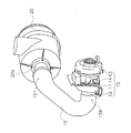
- FIG. 1 is a perspective view showing a configuration of a turbocharger 10 according to the embodiment.
- FIG. 1 the state by which the turbocharger 10 was connected to the air cleaner 20 via the air supply pipe 15 is shown.
- the turbocharger 10 has a compressor housing 11, a suction pipe 12, a turbine housing 13 and a center housing 14.
- the compressor housing 11 accommodates a compressor impeller (not shown).
- the suction pipe 12 is connected to the compressor housing 11.
- the suction pipe 12 sends the air flowing in from the air supply pipe 15 to the compressor impeller.
- the turbine housing 13 accommodates a turbine wheel (not shown).
- the center housing 14 is disposed between the compressor housing 11 and the turbine housing 13 and accommodates a shaft connecting the compressor impeller and the turbine wheel.
- the air supply pipe 15 is a rubber pipe connected to the suction pipe 12 of the turbocharger 10 and the outlet pipe 20 a of the air cleaner 20. Specifically, the air supply pipe 15 has an outlet pipe connection portion 151 connected to the outlet pipe 20 a and a second straight pipe portion 154 connected to the suction pipe 12. The air supply pipe 15 is bent at a position close to each of the suction pipe 12 and the outlet pipe 20a in order to avoid interference with a peripheral member (not shown). The configuration of the air supply pipe 15 will be described later.
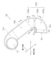
- FIG. 2 is a plan view showing the configuration of the air supply pipe 15 according to the embodiment.
- FIG. 3A to FIG. 3E are cross-sectional views in a cross section perpendicular to the central axis C of the air supply pipe 15 according to the embodiment.
- FIG. 2 is a plan view of the air supply pipe 15 viewed from a third direction orthogonal to the first direction and the second direction.
- the first direction is a direction parallel to the center line of the first straight pipe portion 152
- the second direction is a direction parallel to the center line of the second straight pipe portion 154.
- the third direction is a direction perpendicular to the paper surface of FIG.
- the outer periphery S means an outer periphery along the circumferential direction centering on the axial center of the air supply pipe 15.
- the air supply pipe 15 is configured of an outlet pipe connection portion 151, a first straight pipe portion 152, a curved pipe portion 153, and a second straight pipe portion 154.
- the outlet pipe connection portion 151 is connected to the outlet pipe 20 a of the air cleaner 20 as described above.
- the outlet pipe connection 151 has an inlet T1 that receives the inflowing air from the outlet pipe 20a.
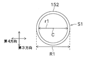
- the first straight pipe portion 152 communicates with the outlet pipe connection portion 151 and the curved pipe portion 153.
- the first straight pipe portion 152 is a straight pipe extending linearly along the first direction, and is formed in a uniform cylindrical shape. Specifically, as shown in FIG. 3A, the first straight pipe portion 152 has a uniform first outer diameter R1 and a uniform first inner diameter r1. That is, how the outer periphery S1 of the first straight pipe portion 152 bends is uniform.
- FIG. 3A is a radial sectional view of the first straight pipe portion 152, that is, an AA sectional view of FIG.
- the curved pipe portion 153 communicates with the first straight pipe portion 152 and the second straight pipe portion 154.
- the curved pipe portion 153 is a cylindrical curved pipe bent from the first straight pipe portion 152 toward the second straight pipe portion 154.
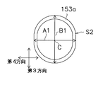
- the curved pipe portion 153 has a first end 153 a, a second end 153 b, and a rectangular pipe portion 153 c.
- the first end 153 a communicates with the first straight pipe portion 152 and the rectangular pipe portion 153 c.
- the second end 153 b communicates with the second straight pipe portion 154 and the rectangular pipe portion 153 c.
- the rectangular tube portion 153c communicates with the first end 153a and the second end 153b.
- the curved tube portion 153 is not formed in a uniform cylindrical shape, but is formed flat in the third direction.
- the cross-sectional shape of the first end portion 153a is a substantially elliptical shape having a major axis in the third direction.
- the width A1 of the first end 153a in the fourth direction orthogonal to the third direction in the plane including the central axis C is smaller than the first outer diameter R1, and the first end 153a in the third direction is The height B1 is substantially the same as the first outer diameter R1 of the first straight pipe portion 152.
- both end portions in the fourth direction of the outer circumference S2 of the first end portion 153a are formed in a straight line along the third direction.
- the cross-sectional shape of the first end portion 153 a is flat in the fourth direction as compared to the cross-sectional shape of the first straight pipe portion 152.
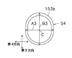
- the cross-sectional shape of the rectangular tube portion 153c is a rectangular shape having a long side in the third direction, as shown in FIG. 3C which is a cross-sectional view taken along the line CC of FIG. Specifically, the width A2 of the rectangular pipe 153c in the fourth direction is smaller than the width A1 of the first end 153a and the width A3 of the second end 153b, and the height B2 of the rectangular pipe 153c in the third direction Is a size between the first outer diameter R1 and the second outer diameter R2 (> R1).
- both ends in the fourth direction of the outer circumference S3 of the rectangular pipe portion 153c are formed in a straight line along the third direction, and both ends in the third direction of the outer circumference S3 of the rectangular pipe portion 153c are in the fourth direction. It is formed in a straight line along.
- the cross-sectional shape of the rectangular tube portion 153 c is flat in the fourth direction as compared to the cross-sectional shape of the first straight tube portion 152.
- the cross-sectional shape of the second end portion 153b is a substantially elliptical shape having a major axis in the third direction, as shown in FIG. 3D which is a cross-sectional view taken along the line DD in FIG.
- the width A3 of the second end 153b in the fourth direction is smaller than the second outer diameter R2 of the second straight pipe portion 154
- the height B3 of the second end 153b in the third direction is The second outer diameter R2 of the second straight pipe portion 154 is substantially the same.
- both end portions in the fourth direction of the outer periphery S4 of the second end portion 153b are formed in a straight line along the third direction.
- the cross-sectional shape of the second end 153 b is flat in the fourth direction as compared to the cross-sectional shape of the second straight pipe portion 154.
- the curved tube portion 153 is formed flat in the third direction as a whole, but is not necessarily formed flat.
- the curved pipe portion 153 is gradually deformed from a cylindrical shape to a rectangular shape at the first end portion 153a, and is gradually deformed from a rectangular shape to a cylindrical shape at the second end portion 153b.
- the second straight pipe portion 154 is connected to the suction pipe 12 as described above.
- the second straight pipe portion 154 has an outlet T2 from which the air flows out.
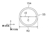
- the second straight pipe portion 154 is a straight pipe extending linearly along the second direction, and is formed in a uniform cylindrical shape.
- the second straight pipe portion 154 has a uniform second outer diameter R2 (> R1) and a uniform second inner diameter r2 (> r1). That is, as in the case of the outer circumference S1 of the first straight pipe portion 152, the outer circumference S4 of the second straight pipe portion 154 bends more rapidly than the bending of the outer circumference (including the outer circumferences S2, S3 and S4) of the curved pipe portion 153. It is.
- FIG. 3E is a cross-sectional view taken along the line EE of FIG.
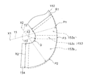
- FIG. 4 is a partial enlarged view of FIG. 2 and is a plan view of the bent pipe portion 153 viewed from the third direction.
- the outer edge P refers to the outer edge of the curved pipe portion 153 viewed from the third direction.
- the outer edge P1 of the first end 153a is bent at a first radius of curvature Y1 about the center point X1.
- the outer edge P2 of the second end 153b is bent at a second radius of curvature Y2 about the center point X2.
- the outer edge P3 of the rectangular tube portion 153c extends linearly and is not bent.
- the first radius of curvature Y1 is a radius of curvature different from the second radius of curvature Y2, and is larger than the second radius of curvature Y2.
- the inner edge Q of the curved tube portion 153 is bent at a third curvature radius Y3 around the center point X3.
- the third radius of curvature Y3 is smaller than the first radius of curvature Y1 and the second radius of curvature Y2.
- the third radius of curvature Y3 is 40% or more of the second outer diameter R2 of the first straight pipe portion 152 and the second straight pipe portion 154.
- the dividable core is set inside the assembly type tube.
- the tube rubber is pushed out and inserted into the assembly type.
- the reinforcing material is wrapped and vulcanized on the inserted tube rubber.
- the core is separated and removed.
- the cross-sectional shape of the curved pipe part 153 is a rectangular shape which has a long side in a 3rd direction. Therefore, compared to the case where the cross-sectional shape of the curved pipe portion 153 is circular, the air supply pipe 15 can be bent in a compact manner in the curved pipe portion 153. Therefore, the piping space of the air supply pipe 15 can be made compact. Further, the strength of the curved pipe portion 153 can be improved as compared with the case where the sectional shape of the curved pipe portion 153 is an elliptical shape or the like. Such an effect is particularly useful in the case where negative pressure is generated inside the air supply pipe 15 due to the suction input of the turbocharger 10.
- the first curvature radius Y1 of the outer edge P1 of the first end 153a is different from the second curvature radius Y2 of the outer edge P2 of the second end 153b. Therefore, it is possible to improve the degree of freedom of how the bent portion 153 bends. Therefore, interference with peripheral members can be effectively avoided while the piping space of the air supply pipe 15 is made compact.
- the inner edge Q of the curved tube portion 153 is bent at a third curvature radius Y3 smaller than the first curvature radius Y1 and the second curvature radius Y2.
- the third radius of curvature Y3 is 40% or more of the second outer diameter R2 of the second straight pipe portion 154.
- the third radius of curvature Y3 is set to 40% or more of the second outer diameter R2, it is possible to suppress that the traveling direction of the air in the curved pipe portion 153 is sharply bent. Therefore, the speed variation of the air flowing out of the outlet T2 of the air supply pipe 15 can be reduced. Therefore, since hunting in the compressor impeller in the compressor housing 11 can be suppressed, damage to the compressor impeller can be suppressed.
- the air supply pipe 15 is a rubber pipe, it is not limited thereto.
- the air supply pipe 15 may be, for example, a cast product formed by a mold.
- the air supply pipe 15 shall be provided in the turbocharger 10, it is not restricted to this.
- the air supply pipe 15 may be provided in a supercharger-type supercharger, a diesel particulate filter processing device, a selective catalytic reduction processing device, or the like.
- the air supply pipe 15 shall be provided in the suction pipe side, it is not restricted to this.
- the air supply pipe 15 may be provided on the exhaust pipe side.
- the first outer diameter R1 of the first straight pipe portion 152 is larger than the second outer diameter R2 of the second straight pipe portion 154, and the first inner diameter r1 of the first straight pipe portion 152 is the second Although larger than the second inner diameter r2 of the straight pipe portion 154, it is not limited thereto.
- the first outer diameter R1 may be smaller than or equal to the second outer diameter R2.
- the first inner diameter r1 may be smaller than or the same as the second inner diameter r2.
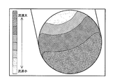
- FIG. 5A is a simulation result in the case where the air supply pipe according to the embodiment is applied.
- FIG. 5B is a simulation result in the case of applying a flue according to the conventional example.
- the variation in air velocity difference between the maximum flow velocity and the minimum flow velocity
- the air supply pipe 15 which concerns on the said embodiment, it was confirmed that stable supply of air can be performed.
Abstract
Description
しかしながら、特許文献1に記載の送気管は一様な円筒形状に形成されているので、送気管のうち折り曲げられた部分が周辺部材に向かって突出してしまう。そのため、送気管の配管スペースをコンパクト化するにも限界がある。 (Problems to be solved by the invention)
However, since the air supply pipe described in
(課題を解決するための手段)
本発明の第1の態様に係る送気管は、第1端部と、第2端部と、第1端部及び第2端部に連通する矩形管部と、を有する筒状の曲管部と、第1方向に沿って第1端部から延びており、第1外径を有する円筒状の第1直管部と、第1方向と交差する第2方向に沿って第2端部から延びており、第2外径を有する円筒状の第2直管部と、を備える。前記曲管部の中心軸に垂直な切断面における曲管部の断面形状は、第1方向及び第2方向と直交する第3方向において長辺を有する矩形状である。 The present invention has been made in view of the above situation, and it is an object of the present invention to provide an air supply pipe capable of compacting a piping space, and a supercharger including the air supply pipe.
(Means to solve the problem)
The air supply pipe according to the first aspect of the present invention has a cylindrical curved pipe portion having a first end, a second end, and a rectangular pipe communicating with the first end and the second end. And a cylindrical first straight pipe portion extending from the first end along the first direction and having a first outer diameter, and from the second end along a second direction intersecting the first direction. And a cylindrical second straight section having a second outer diameter. The cross-sectional shape of the curved pipe portion in a cutting plane perpendicular to the central axis of the curved pipe portion is a rectangular shape having a long side in a first direction and a third direction orthogonal to the second direction.
(発明の効果)
本発明によれば、配管スペースをコンパクト化可能な送気管、及びその送気管を備える過給器を提供することができる。 A supercharger according to a sixth aspect of the present invention comprises a compressor housing for housing a compressor impeller, a suction pipe for sending air into the compressor, and a gas feed pipe according to any of the first to sixth aspects. Prepare. The second straight pipe portion is connected to the suction pipe.
(Effect of the invention)
According to the present invention, it is possible to provide an air supply pipe capable of compacting a piping space, and a supercharger including the air supply pipe.
実施形態に係るターボ過給器10の構成について、図面を参照しながら説明する。図1は、実施形態に係るターボ過給器10の構成を示す斜視図である。なお、図1では、ターボ過給器10が送気管15を介してエアクリーナ20に接続された状態が示されている。 (Configuration of turbo charger 10)
The configuration of the
実施形態に係る送気管15の構成について、図面を参照しながら説明する。図2は、実施形態に係る送気管15の構成を示す平面図である。図3A~図3Eは、実施形態に係る送気管15の中心軸Cに垂直な切断面における断面図である。なお、図2は、第1方向及び第2方向と直交する第3方向から見た送気管15の平面図である。第1方向とは、第1直管部152の中心線に平行な方向であり、第2方向とは、第2直管部154の中心線に平行な方向である。第3方向とは、図2の紙面に垂直な方向である。また、以下の説明において、外周Sとは、送気管15の軸心を中心とする周方向に沿った外周を意味する。 (Configuration of air supply tube 15)
The configuration of the
実施形態に係る曲管部153における折れ曲がり方について、図面を参照しながら説明する。図4は、図2の部分拡大図であり、第3方向から見た曲管部153の平面図である。なお、以下の説明において、外側縁Pとは、第3方向から見た曲管部153の外側縁のことある。 (How to bend in the bent portion 153)
The bending method of the
まず、組立型のチューブ内側に分割可能な中子をセットする。次に、チューブゴムを押し出して組立型に挿入する。次に、挿入されたチューブゴムに補強材をラッピングして加硫する。最後に、組立型を分解した後、中子を分割しながら抜き取る。 (Method of manufacturing air pipe 15)
First, the dividable core is set inside the assembly type tube. Next, the tube rubber is pushed out and inserted into the assembly type. Next, the reinforcing material is wrapped and vulcanized on the inserted tube rubber. Finally, after disassembling the assembly type, the core is separated and removed.
(1)実施形態に係る送気管15において、曲管部153の断面形状は、第3方向において長辺を有する矩形状である。そのため、曲管部153の断面形状が円形である場合に比べて、送気管15を曲管部153においてコンパクトに折り曲げることができる。従って、送気管15の配管スペースをコンパクト化することができる。また、曲管部153の断面形状が楕円形などである場合に比べて、曲管部153の強度を向上させることができる。このような効果は、ターボ過給器10の吸入力によって送気管15の内部で負圧が発生する場合に特に有用である。 (Action and effect)
(1) In the
以上、本発明の一実施形態について説明したが、本発明は上記実施形態に限定されるものではなく、発明の要旨を逸脱しない範囲で種々の変更が可能である。 (Other embodiments)
As mentioned above, although one Embodiment of this invention was described, this invention is not limited to the said embodiment, A various change is possible in the range which does not deviate from the summary of invention.
11 コンプレッサハウジング
12 吸入管
13 タービンハウジング
14 センターハウジング
15 送気管
151 出口管接続部
152 第1直管部
153 曲管部
153a 第1端部
153b 第2端部
153c 矩形管部
154 第2直管部
20 エアクリーナ
20a 出口管
S 送気管15の周方向に沿った外周縁
P 送気管15の延在方向に沿った外側縁
Q 曲管部153の延在方向に沿った内側縁
A 第4方向における幅
B 第3方向における高さ
C 送気管15の中心軸 DESCRIPTION OF
Claims (6)
- 第1端部と、第2端部と、前記第1端部及び前記第2端部に連通する矩形管部と、を有する筒状の曲管部と、
第1方向に沿って前記第1端部から延びており、第1外径を有する円筒状の第1直管部と、
前記第1方向と交差する第2方向に沿って前記第2端部から延びており、第2外径を有する円筒状の第2直管部と、
を備え、
前記曲管部の中心軸に垂直な切断面における前記矩形管部の断面形状は、前記第1方向及び前記第2方向と直交する第3方向において長辺を有する矩形状である、
送気管。 A cylindrical curved tube having a first end, a second end, and a rectangular tube communicating with the first end and the second end;
A cylindrical first straight pipe portion extending from the first end along a first direction and having a first outer diameter;
A cylindrical second straight pipe portion extending from the second end along a second direction intersecting the first direction and having a second outer diameter;
Equipped with
The cross-sectional shape of the rectangular tube portion in a cutting plane perpendicular to the central axis of the curved tube portion is a rectangular shape having long sides in the first direction and a third direction orthogonal to the second direction.
Air supply. - 前記第3方向から見た前記第1端部の外側縁は、第1曲率半径で曲がっており、
前記第3方向から見た前記第2端部の外側縁は、前記第1曲率半径とは異なる第2曲率半径で曲がっている、
請求項1に記載の送気管。 The outer edge of the first end viewed from the third direction is curved at a first radius of curvature,
The outer edge of the second end viewed from the third direction is bent at a second radius of curvature different from the first radius of curvature.
The air supply pipe according to claim 1. - 前記第3方向から見た前記矩形管部の外側縁は、直線的に延びる、
請求項2に記載の送気管。 The outer edge of the rectangular tube portion viewed from the third direction extends linearly,
The air supply pipe according to claim 2. - 前記第3方向から見た前記曲管部の内側縁は、前記第1曲率半径及び前記第2曲率半径よりも小さい第3曲率半径で曲がっている、
請求項2又は3に記載の送気管。 An inner edge of the curved tube portion viewed from the third direction is bent at a third curvature radius smaller than the first curvature radius and the second curvature radius.
The air supply pipe according to claim 2 or 3. - 前記第3曲率半径は、前記第2外径の40%以上である、
請求項4に記載の送気管。 The third radius of curvature is 40% or more of the second outer diameter.
The air supply pipe according to claim 4. - コンプレッサインペラを収容するコンプレッサハウジングと、
前記コンプレッサ内に空気を送る吸入管と、
請求項1乃至5のいずれかに記載の送気管と、
を備え、
前記第2直管部は、前記吸入管に連結される、
過給器。 A compressor housing for housing a compressor impeller;
An intake pipe for feeding air into the compressor;
The air supply pipe according to any one of claims 1 to 5, and
Equipped with
The second straight pipe portion is connected to the suction pipe.
Supercharger.
Priority Applications (2)
| Application Number | Priority Date | Filing Date | Title |
|---|---|---|---|
| CN201280002146.9A CN103026043B (en) | 2011-01-21 | 2012-01-19 | Air delivery pipe and supercharger |
| US13/809,152 US8555637B2 (en) | 2011-01-21 | 2012-01-19 | Work vehicle |
Applications Claiming Priority (2)
| Application Number | Priority Date | Filing Date | Title |
|---|---|---|---|
| JP2011011440A JP5228069B2 (en) | 2011-01-21 | 2011-01-21 | Air pipe and supercharger |
| JP2011-011440 | 2011-01-21 |
Publications (1)
| Publication Number | Publication Date |
|---|---|
| WO2012099191A1 true WO2012099191A1 (en) | 2012-07-26 |
Family
ID=46515813
Family Applications (1)
| Application Number | Title | Priority Date | Filing Date |
|---|---|---|---|
| PCT/JP2012/051048 WO2012099191A1 (en) | 2011-01-21 | 2012-01-19 | Air delivery pipe and supercharger |
Country Status (4)
| Country | Link |
|---|---|
| US (1) | US8555637B2 (en) |
| JP (1) | JP5228069B2 (en) |
| CN (1) | CN103026043B (en) |
| WO (1) | WO2012099191A1 (en) |
Cited By (2)
| Publication number | Priority date | Publication date | Assignee | Title |
|---|---|---|---|---|
| WO2014007178A1 (en) * | 2012-07-04 | 2014-01-09 | アイシン精機株式会社 | Air flow control device |
| CN104919170A (en) * | 2013-01-16 | 2015-09-16 | 丰田自动车株式会社 | Internal combustion engine with supercharger |
Families Citing this family (10)
| Publication number | Priority date | Publication date | Assignee | Title |
|---|---|---|---|---|
| JP2012171596A (en) * | 2011-02-24 | 2012-09-10 | Hitachi Constr Mach Co Ltd | Construction machine |
| WO2014128896A1 (en) * | 2013-02-21 | 2014-08-28 | 三菱重工業株式会社 | Fluid machine and fluid machine system equipped with same |
| JP5967058B2 (en) * | 2013-11-20 | 2016-08-10 | コベルコ建機株式会社 | Piping material for air cleaner |
| US9598091B2 (en) | 2014-09-29 | 2017-03-21 | Electro-Motive Diesel, Inc. | Air intake system for an engine |
| US9845722B2 (en) * | 2014-09-29 | 2017-12-19 | Electro-Motive Diesel, Inc. | Engine system for emissions compliance |
| US20160245162A1 (en) * | 2015-02-20 | 2016-08-25 | Pratt & Whitney Canada Corp. | Compound engine assembly with offset turbine shaft, engine shaft and inlet duct |
| DE102015226807A1 (en) * | 2015-12-29 | 2017-06-29 | Robert Bosch Gmbh | Component for fuel injection system and method for manufacturing a component of a fuel injection system |
| JP6762724B2 (en) * | 2016-01-22 | 2020-09-30 | 三菱重工コンプレッサ株式会社 | Piping of driven fluid machinery |
| WO2018044308A1 (en) * | 2016-08-31 | 2018-03-08 | Cummins Inc. | Cobra head air intake ports and intake manifolds |
| US11098681B2 (en) | 2016-08-31 | 2021-08-24 | Cummins Inc. | Cobra head air intake ports and intake manifolds |
Citations (6)
| Publication number | Priority date | Publication date | Assignee | Title |
|---|---|---|---|---|
| JPS5960382U (en) * | 1982-10-16 | 1984-04-20 | 本田技研工業株式会社 | Motorcycle connecting tube |
| JPS61198562U (en) * | 1985-06-03 | 1986-12-11 | ||
| JPH0368528U (en) * | 1989-11-08 | 1991-07-05 | ||
| JPH08510809A (en) * | 1992-09-08 | 1996-11-12 | シーメンス エレクトリック リミテッド | Active manifold |
| JP2005113912A (en) * | 2003-10-06 | 2005-04-28 | Filterwerk Mann & Hummel Gmbh | Intake module particularly for internal combustion engine |
| JP2009299589A (en) * | 2008-06-13 | 2009-12-24 | Toyoda Gosei Co Ltd | Intake system component |
Family Cites Families (15)
| Publication number | Priority date | Publication date | Assignee | Title |
|---|---|---|---|---|
| JPS5036905U (en) * | 1973-08-09 | 1975-04-17 | ||
| JPH082430Y2 (en) * | 1990-06-18 | 1996-01-29 | ダイハツ工業株式会社 | Intake manifold in internal combustion engine |
| JP3509217B2 (en) * | 1994-09-20 | 2004-03-22 | 株式会社日立製作所 | Forming method and forming apparatus for deformed cross-section pipe |
| JP2902364B2 (en) * | 1996-10-14 | 1999-06-07 | バンドー化学株式会社 | Hollow tubular body for air intake duct, molding die thereof and molding method thereof |
| JP3329220B2 (en) * | 1997-01-31 | 2002-09-30 | スズキ株式会社 | Intake structure of supercharged engine |
| JP4090609B2 (en) * | 1999-01-19 | 2008-05-28 | 株式会社イノアックコーポレーション | Air intake duct |
| JP2003254490A (en) * | 2002-03-01 | 2003-09-10 | Toyota Motor Corp | Fluid passage having bend part |
| US7089963B2 (en) * | 2002-11-26 | 2006-08-15 | David Meheen | Flow laminarizing device |
| US7093589B2 (en) * | 2004-01-08 | 2006-08-22 | Visteon Global Technologies, Inc. | Apparatus for increasing induction air flow rate to a turbocharger |
| JP4458423B2 (en) | 2005-03-02 | 2010-04-28 | キャタピラージャパン株式会社 | Air intake device for construction machinery |
| CN101688383B (en) * | 2007-06-26 | 2012-08-08 | 日立建机株式会社 | Construction machine |
| US7556009B2 (en) * | 2007-09-07 | 2009-07-07 | Advanced Flow Engineering, Inc. | Air intake manifold for coupling the output of a compressor to the air intake of an internal combustion engine |
| JP5234693B2 (en) * | 2009-10-16 | 2013-07-10 | 日立建機株式会社 | Construction machinery |
| DE102010019931A1 (en) * | 2010-05-08 | 2011-11-10 | Volkswagen Ag | Combustion air prominent fluid conduit portion for combustion air system of internal combustion engine, has terminal for fluid conduit formed at bent tube to lead crank case ventilation gas |
| CN102639831A (en) * | 2010-05-31 | 2012-08-15 | 株式会社小松制作所 | Work vehicle |
-
2011
- 2011-01-21 JP JP2011011440A patent/JP5228069B2/en not_active Expired - Fee Related
-
2012
- 2012-01-19 US US13/809,152 patent/US8555637B2/en not_active Expired - Fee Related
- 2012-01-19 CN CN201280002146.9A patent/CN103026043B/en not_active Expired - Fee Related
- 2012-01-19 WO PCT/JP2012/051048 patent/WO2012099191A1/en active Application Filing
Patent Citations (6)
| Publication number | Priority date | Publication date | Assignee | Title |
|---|---|---|---|---|
| JPS5960382U (en) * | 1982-10-16 | 1984-04-20 | 本田技研工業株式会社 | Motorcycle connecting tube |
| JPS61198562U (en) * | 1985-06-03 | 1986-12-11 | ||
| JPH0368528U (en) * | 1989-11-08 | 1991-07-05 | ||
| JPH08510809A (en) * | 1992-09-08 | 1996-11-12 | シーメンス エレクトリック リミテッド | Active manifold |
| JP2005113912A (en) * | 2003-10-06 | 2005-04-28 | Filterwerk Mann & Hummel Gmbh | Intake module particularly for internal combustion engine |
| JP2009299589A (en) * | 2008-06-13 | 2009-12-24 | Toyoda Gosei Co Ltd | Intake system component |
Cited By (3)
| Publication number | Priority date | Publication date | Assignee | Title |
|---|---|---|---|---|
| WO2014007178A1 (en) * | 2012-07-04 | 2014-01-09 | アイシン精機株式会社 | Air flow control device |
| JP2014013014A (en) * | 2012-07-04 | 2014-01-23 | Aisin Seiki Co Ltd | Air flow control device |
| CN104919170A (en) * | 2013-01-16 | 2015-09-16 | 丰田自动车株式会社 | Internal combustion engine with supercharger |
Also Published As
| Publication number | Publication date |
|---|---|
| JP5228069B2 (en) | 2013-07-03 |
| US20130112298A1 (en) | 2013-05-09 |
| US8555637B2 (en) | 2013-10-15 |
| JP2012154182A (en) | 2012-08-16 |
| CN103026043B (en) | 2014-06-11 |
| CN103026043A (en) | 2013-04-03 |
Similar Documents
| Publication | Publication Date | Title |
|---|---|---|
| WO2012099191A1 (en) | Air delivery pipe and supercharger | |
| CN102221016B (en) | Compressor gas flow deflector and compressor incorporating the same | |
| US10378557B2 (en) | Reduced noise compressor recirculation | |
| CN103133194B (en) | There is the silencing means of the resonator insert that can import circular pipe | |
| JP6352936B2 (en) | Centrifugal compressor with twisted return channel vanes | |
| CN102333963B (en) | Suction casing and fluid machine | |
| WO2016071959A1 (en) | Turbine housing and method for manufacturing turbine housing | |
| JP5107148B2 (en) | Turbine engine exhaust cowling | |
| CN105370586B (en) | Cross flow fan | |
| WO2015099199A1 (en) | Turbine | |
| WO2017109949A1 (en) | Centrifugal compressor and turbocharger | |
| JP2009228549A (en) | Centrifugal compressor | |
| JP2007077860A (en) | Air current noise reduction device for supercharger | |
| EP2495426A1 (en) | Swirl guiding acoustic device with an internal coaxially integrated swirl guide structure | |
| JP2013019385A (en) | Centrifugal compressor | |
| US10443414B2 (en) | Turbine casing, turbine, core for casting turbine casing, and method for producing turbine casing | |
| JP6559805B2 (en) | Compressor impeller and manufacturing method thereof | |
| JP6885729B2 (en) | Turbomachinery inlet nozzle for asymmetric flow with differently shaped vanes | |
| CN112204288B (en) | Fluid pipeline | |
| JP6633761B2 (en) | Turbine and turbocharger | |
| CN203925707U (en) | There is the vent systems of mobile rotatable member | |
| CN208186648U (en) | Air-conditioner outdoor unit and air conditioner | |
| JP6889750B2 (en) | Diffuser ducts and turbines for turbines | |
| CN203847294U (en) | Internal combustion engine intake pipe | |
| KR20130065600A (en) | Acoustic resonator of a system for piping gas of an internal combustion engine and a process for manufacturing an acoustic resonator |
Legal Events
| Date | Code | Title | Description |
|---|---|---|---|
| WWE | Wipo information: entry into national phase |
Ref document number: 201280002146.9 Country of ref document: CN |
|
| 121 | Ep: the epo has been informed by wipo that ep was designated in this application |
Ref document number: 12736108 Country of ref document: EP Kind code of ref document: A1 |
|
| WWE | Wipo information: entry into national phase |
Ref document number: 13809152 Country of ref document: US |
|
| NENP | Non-entry into the national phase |
Ref country code: DE |
|
| 122 | Ep: pct application non-entry in european phase |
Ref document number: 12736108 Country of ref document: EP Kind code of ref document: A1 |