WO2012093885A2 - 무선통신 시스템에서 기기내 공존 간섭을 조정하는 장치 및 방법 - Google Patents
무선통신 시스템에서 기기내 공존 간섭을 조정하는 장치 및 방법 Download PDFInfo
- Publication number
- WO2012093885A2 WO2012093885A2 PCT/KR2012/000145 KR2012000145W WO2012093885A2 WO 2012093885 A2 WO2012093885 A2 WO 2012093885A2 KR 2012000145 W KR2012000145 W KR 2012000145W WO 2012093885 A2 WO2012093885 A2 WO 2012093885A2
- Authority
- WO
- WIPO (PCT)
- Prior art keywords
- interference
- information
- frequency band
- band
- terminal
- Prior art date
- Legal status (The legal status is an assumption and is not a legal conclusion. Google has not performed a legal analysis and makes no representation as to the accuracy of the status listed.)
- Ceased
Links
Images


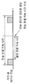


Classifications
-
- H—ELECTRICITY
- H04—ELECTRIC COMMUNICATION TECHNIQUE
- H04W—WIRELESS COMMUNICATION NETWORKS
- H04W16/00—Network planning, e.g. coverage or traffic planning tools; Network deployment, e.g. resource partitioning or cells structures
- H04W16/14—Spectrum sharing arrangements between different networks
Definitions
- the present invention relates to wireless communications, and more particularly, to an apparatus and method for coordinating in-device coexistence interference in a wireless communication system.
- Wireless communication systems generally use one bandwidth for data transmission.
- the second generation wireless communication system uses a bandwidth of 200KHz ⁇ 1.25MHz
- the third generation wireless communication system uses a bandwidth of 5MHz ⁇ 10MHz.
- 3GPP 3rd Generation Partnership Project
- LTE Long Term Evolution
- IEEE 802.16m continues to expand its bandwidth to 20 MHz or more.
- even when the level of service required is low, supporting a large bandwidth can cause a large power consumption.
- a multiple component carrier system which defines a carrier having one bandwidth and a center frequency and enables transmission and / or reception of data over a wide band through a plurality of carriers.
- one or more carriers By using one or more carriers, both narrow and wide bandwidths are supported simultaneously. For example, if one carrier corresponds to a bandwidth of 5 MHz, four carriers are used to support a maximum bandwidth of 20 MHz.
- in-device coexistence interference refers to interference when transmission in one frequency band interferes with reception in another frequency band in the same terminal.
- in-device coexistence interference may be performed between a Bluetooth system band and an 802.16 system band when one terminal simultaneously supports a Bluetooth system and an 802.16 system.
- In-device coexistence interference may occur mainly when the separation intervals of the frequency band boundaries of heterogeneous network systems are not wide enough.
- FDM frequency division multiplexing
- the FDM method adjusts interference avoiding a band in which coexistence interference occurs in a device.
- a specific operation procedure between the terminal and the base station for coordinating in-device coexistence interference by the FDM scheme has not been discussed yet.
- An object of the present invention is to provide an apparatus and method for adjusting in-device coexistence interference.
- Another object of the present invention is to provide an apparatus and method for detecting whether in-device coexistence interference occurs.
- Another technical problem of the present invention is to provide an apparatus and method for transmitting information about in-device coexistence interference in a wireless communication system.
- Another technical problem of the present invention is to provide an apparatus and method for adjusting in-device coexistence interference by frequency shift.
- Another technical problem of the present invention is to provide an apparatus and method for adjusting in-device coexistence interference by frequency shaping.
- a method of interference coordination by a terminal in a wireless communication system includes detecting interference caused by transmission in a first frequency band of a first network system to reception in a second frequency band of a second network system, and providing support information to assist in the adjustment of the detected interference. And receiving response information from the base station accepting or rejecting adjustment of the detected interference in response to the assistance information.
- a terminal for performing interference coordination in a wireless communication system generates an interference detector for detecting interference caused by transmission in a first frequency band of a first network system to reception in a second frequency band of a second network system, and generating assistance information to support adjustment of the detected interference.
- a support information generator for transmitting the support information to the base station, and a response information receiver for receiving response information from the base station for accepting or rejecting the adjustment of the detected interference in response to the support information.
- a base station for performing interference coordination in a wireless communication system.
- the base station includes a support information receiver for receiving, from the terminal, support information that is information about interference caused by transmission in a first frequency band of a first network system for reception in a second frequency band of a second network system.
- An interference coordination determining unit for determining whether to coordination, a response information transmitter for transmitting response information for accepting or rejecting the coordination of interference, and a scheduling unit for performing scheduling for coordinating the interference.
- the procedure for handling in-device co-existence interference is simplified, easy to implement and maintain backward compatibility with other existing procedures.
- information on in-device coexistence interference exchanged between the terminal and the base station is clearly defined, the uncertainty of the interference coordination procedure can be solved.
- FIG. 1 illustrates a wireless communication system to which embodiments of the present invention are applied.
- FIG 3 shows an example of in-device coexistence interference from an ISM transmitter to an LTE receiver.
- FIG. 4 shows an example in which an ISM band and an LTE band are divided on a frequency band.
- FIG. 5 is an explanatory diagram illustrating an example of mitigating in-device interference using an FDM scheme.
- FIG 6 is an explanatory diagram showing another example of mitigating in-device interference using the FDM scheme.
- FIG. 7 is an explanatory diagram illustrating an example of mitigating in-device interference using a TDM scheme.
- FIG. 9 is a flowchart illustrating a method of transmitting information about in-device coexistence interference according to an embodiment of the present invention.
- 10 and 11 illustrate a method of detecting in-device coexistence interference according to an embodiment of the present invention.
- 12 to 14 illustrate a method of detecting in-device coexistence interference according to another embodiment of the present invention.
- 15 to 17 are diagrams for describing a method of adjusting in-device coexistence interference by frequency shifting or shaping according to an embodiment of the present invention.
- FIG. 18 is a flowchart illustrating a method of transmitting information about in-device coexistence interference by a terminal according to an embodiment of the present invention.
- 19 is a flowchart illustrating a method of transmitting information about in-device coexistence interference by a base station according to an embodiment of the present invention.
- 20 is a block diagram illustrating an apparatus for transmitting information about in-device coexistence interference according to an embodiment of the present invention.
- first, second, A, B, (a), and (b) may be used. These terms are only for distinguishing the components from other components, and the nature, order or order of the components are not limited by the terms. If a component is described as being “connected”, “coupled” or “connected” to another component, that component may be directly connected or connected to that other component, but there is another component between each component. It will be understood that may be “connected”, “coupled” or “connected”.
- the present specification describes a wireless communication network
- the operation performed in the wireless communication network is performed in the process of controlling the network and transmitting data in the system (for example, the base station) that manages the wireless communication network, or the corresponding wireless Work may be done at the terminal coupled to the network.
- a wireless communication system is widely deployed to provide various communication services such as voice and packet data, and includes a user equipment (UE), a base station 20 (evolved NodeB, eNodeB, eNB), and a radio.
- Wireless LAN Access Point (AP) 30, GPS (Global Positioning System, 40) satellite (satellite).
- the WLAN is a device that supports the IEEE 802.11 technology, which is a wireless standard, and IEEE 802.11 may be mixed with a Wi-Fi system.
- the terminal 10 may be located within the coverage of multiple networks such as cellular networks, wireless LANs, broadcast networks, satellite systems, and the like.
- the terminal 10 is provided with a plurality of radio transceivers.
- a smart phone includes a Long Term Evolution (LTE), WiFi, Bluetooth (BT) transceiver or a GPS receiver.
- LTE Long Term Evolution
- WiFi Wireless Fidelity
- BT Bluetooth
- GPS receiver GPS receiver
- downlink means communication from the base station 20 to the terminal 10
- uplink means communication from the terminal 10 to the base station 20.
- the transmitter may be part of the base station 20 and the receiver may be part of the terminal 10.
- the transmitter in uplink, may be part of the terminal 10 and the receiver may be part of the base station 20.
- the terminal 10 may be fixed or mobile, and may be called by other terms such as a mobile station (MS), a user terminal (UT), a subscriber station (SS), a mobile terminal (MT), and a wireless device.
- the base station 20 refers to a fixed station that communicates with the terminal 10, and includes a base station (BS), a base transceiver system (BTS), an access point, an femto base station, and a relay. It may be called in other terms such as relay.
- CDMA Code Division Multiple Access
- TDMA Time Division Multiple Access
- FDMA Frequency Division Multiple Access
- OFDMA Orthogonal Frequency Division Multiple Access
- SC-FDMA Single Carrier-FDMA
- OFDM-FDMA OFDM-TDMA
- various multiple access schemes such as OFDM-CDMA may be used.
- the uplink transmission and the downlink transmission may use a time division duplex (TDD) scheme that is transmitted using different times, or may use a frequency division duplex (FDD) scheme that is transmitted using different frequencies.
- TDD time division duplex
- FDD frequency division duplex
- Carrier aggregation supports a plurality of component carriers and is also called spectrum aggregation or bandwidth aggregation. Individual unit carriers bound by carrier aggregation are called component carriers (CC). Each CC is defined by a bandwidth and a center frequency. Carrier aggregation is introduced to support increased throughput, to prevent cost increase due to the introduction of wideband radio frequency (RF) devices, and to ensure compatibility with existing systems. For example, if five CCs are allocated as granularity in a carrier unit having a 5 MHz bandwidth, a bandwidth of up to 25 MHz may be supported.
- a multiple carrier system refers to a system supporting carrier aggregation.
- the wireless communication system of FIG. 1 may be a multi-carrier system.
- the system frequency band is divided into a plurality of carrier frequencies.
- the carrier frequency means a center frequency of the cell.
- the cell may mean a downlink CC and an uplink CC.
- the cell may mean a combination of a downlink CC and an optional uplink CC.
- uplink and downlink CCs always exist in pairs in one cell.
- the terminal 10 includes an LTE RF 21, a GPS RF 22, and a Bluetooth / WiFi RF 23. Transmit and receive antennas 24, 25, 26 are connected to each RF. That is, several kinds of RFs are closely mounted in one device platform. Here, the transmit power of one RF may be much greater than the receive power level of other RFs. If the frequency spacing between the RFs is not sufficient and the filtering technique is not supported, then the transmission signal of one RF may cause significant interference to the receiver of another RF in the device.
- (1) is an example in which a transmission signal of the LTE RF 21 causes in-device coexistence interference with respect to the GPS RF 22 and the Bluetooth / WiFi RF 23, and (2) the Bluetooth / WiFi RF ( 23 is an example of causing in-device coexistence interference with respect to the LTE RF 21.
- the ISM (Industrial, Scientific and Medical) band represents a band that can be freely used without a license in the industrial science and medical field, and the ISM RF transmits and receives signals in the ISM band.
- the band of the signal received at the LTE receiver overlaps the band of the transmission signal of the ISM transmitter. In this case, in-device coexistence interference may occur.
- FIG. 4 is a diagram illustrating an example in which an ISM band and an LTE band are divided on a frequency band.
- band 40, band 7, and band 38 are LTE bands.
- Band 40 occupies 2300-2400 MHz band in TDD mode
- band 7 occupies 2500-2570 MHz band as uplink in FDD mode.
- Band 38 occupies 2570-2620 MHz band in TDD mode.
- the ISM band is used as a WiFi channel and a Bluetooth channel and occupies 2400 to 2483.5 MHz. In this case, the situation where in-device coexistence interference occurs is shown in the following table.
- the notation 'a-b' in the form of interference indicates a situation in which transmitter a causes in-device coexistence interference to receiver b.
- the ISM transmitter causes in-device co-existence interference to the downlink TDD receiver (LTE TDD DL Rx) of the LTE band.
- a filtering scheme can mitigate in-device coexistence interference to some extent, but it is not enough.
- the following FDM method can more effectively mitigate in-device coexistence interference.
- FIG. 5 is an explanatory diagram illustrating an example of mitigating in-device interference using an FDM scheme.
- the LTE band may be moved so that the LTE band does not overlap with the ISM band. This results in handover of the terminal from the ISM band.
- this requires a method in which legacy measurement or new signaling accurately triggers a mobility procedure or a radio link failure (RLF) procedure.
- RLF radio link failure
- FIG 6 is an explanatory diagram showing another example of mitigating in-device interference using the FDM scheme.
- the ISM band may be reduced and moved away from the LTE band.
- backward compatibility problems may arise in this manner.
- the backward compatibility problem may be solved to some extent due to the adaptive frequency hopping mechanism, but in the case of WiFi, the backward compatibility problem may be difficult to solve.
- FIG. 7 is an explanatory diagram illustrating an example of mitigating in-device interference using a TDM scheme.
- the reception time in the LTE band does not overlap with the transmission time in the ISM band, in-device coexistence interference may be avoided.
- the signal of the ISM band is transmitted at t 0
- the signal of the LTE band is received at t 1 .
- the transmission and reception timing of the LTE band and the ISM band using the TDM scheme are shown in FIG. 8.
- in-device coexistence interference may be avoided because the reception time in the LTE band and the transmission time in the ISM band do not overlap without the movement between the LTE band and the ISM band.
- FIG. 9 is a flowchart illustrating a method of transmitting information about in-device coexistence interference according to an embodiment of the present invention.
- the terminal detects in-device coexistence interference (S900).
- In-device coexistence interference may be a case where a transmission from a terminal to a peripheral device (communication) communicating via Bluetooth or WiFi causes interference in reception from a base station of the LTE system of the terminal.
- the terminal transmits a signal y through another RF such as WiFi while receiving the signal x from the base station through the LTE RF.
- the terminal detects whether a transmission signal of another RF interferes with the received signal of the LTE RF.
- the terminal may detect in-device co-existence interference using a received signal to interference noise ratio (SINR).
- SINR received signal to interference noise ratio
- the terminal may detect occurrence of in-device coexistence interference.
- the terminal may detect in-device coexistence interference using RSRP (Reference Signal Received Power) or RSRQ (Reference Signal Received Quality).
- RSRP Reference Signal Received Power
- RSRQ Reference Signal Received Quality
- the terminal may define a blank transmission area for the transmission of the peripheral device to impose a limitation on the transmission resource of the peripheral device.
- the blank transmission may be an example of a TDM scheme.
- too low a transmission rate may be allocated to the peripheral device according to a situation, such that a service such as voice or streaming may be impossible.
- the terminal may retry interference coordination based on the FDM scheme.
- the terminal may detect in-device coexistence interference.
- the terminal may determine and detect that in-device coexistence interference has occurred.
- the terminal may detect that there is interference.
- the terminal may set a transmission determination duration and an interruption determination duration in advance, and detect in-device coexistence interference using the same.
- a transmission discrimination duration (or referred to as a transmission discrimination duration)
- signal transmission is maintained. We judge that it is. If the transmission of the signal is maintained during the transmission determination duration, the terminal detects in-device coexistence interference. Even if the transmission of the signal does not continue and stops in the middle, if the signal is transmitted again within a predetermined time (interruption determination duration of FIG. 10), the terminal determines that the transmission of the signal is maintained and detects coexistence interference.
- SINR can be used to detect in-device resonant interference
- RSRP or RSRQ can be used to detect in-device co-existence interference
- the terminal When receiving the signal z through the ISM RF, if the strength of the interference of the measured signal u is greater than or equal to a certain threshold, or if the condition of the strength of the interference of the signal u is greater than or equal to a certain threshold is maintained for a predetermined time It can be determined and detected that a coexistence interference has occurred. As such, when it is determined that the transmission of the LTE RF causes interference so that reception in the ISM band is difficult, the terminal may detect coexistence interference.
- the definition of data transmission may be defined in a state in which the intensity of the interference of the signal u is larger than a predetermined threshold.
- the intensity of the interference of the signal u falls below a certain threshold, it may be defined as a state in which data transmission is stopped.
- the terminal may determine whether to detect in-device coexistence interference on the basis of that in-device coexistence interference is not detected for a predetermined time as shown in FIGS. 12 to 14.
- the no-transmission determination duration is a time at which it is determined that a meaningful transmission that generates coexistence interference does not occur until the corresponding time since transmission is terminated.
- the transmission discrimination duration is distinguished from the time at which it is assumed that a meaningful data transmission has occurred since the data transmission has been continued for a corresponding time since the data transmission starts.
- the terminal when a terminal transmits a signal y through another RF such as WiFi while receiving a signal x from a base station through LTE RF, the terminal coexists if the transmission of the signal y does not occur during the corresponding duration. You can judge that there is no.
- the transmission of the signal y may mean data transmission itself, or may mean when the strength of the interference measured in the LTE RF is greater than the threshold or when the SINR value measured in the LTE RF is smaller than the threshold.
- 13 and 14 illustrate a method of detecting in-device coexistence interference according to another embodiment of the present invention.
- Transmission of data that does not last for a certain period of time is considered insufficient to generate coexistence interference, so it is not regarded as coexistence interference. This is called "no transmission.”
- the terminal may determine that coexistence interference does not occur when a situation in which data transmission does not occur is maintained for no transmission determination duration.
- an interference signal should be transmitted for a transmission determination duration in order to be detected as an interference signal. If a signal is detected for less than the transmission determination duration, no data transmission is assumed. If no signal is detected during the no-transmission determination duration, it may be determined that no transmission and no interference signal is generated. No transmission of signal y may mean that no data transmission itself occurs, and may be interpreted when the strength of the interference is measured below the threshold on the LTE side, or when the SINR value measured on the LTE side is greater than the threshold. .
- the terminal detects in-device interference. After the transmission of the signal causing the coexistence interference again is stopped, the no transmission transmission determination duration is reset, and the timer related to the no transmission determination duration is restarted.
- in-device coexistence interference Although the occurrence of in-device coexistence interference is detected in FIG. 9, there may be a process of preventing interference information from being transmitted to the base station due to in-device coexistence interference. This is a way to prevent the process of co-existing interference, which changes variably, from occurring too often.
- a prohibition timer may be used, wherein the in-device co-existence interference is reestablished while the prohibit timer is in operation after the occurrence of in-device coexistence interference is detected and the interference information is transmitted from the terminal to the base station. Even if detected once, the interference information cannot be transmitted to the base station. By doing so, it is possible to prevent the transmission of the interference information caused by too much in-device coexistence interference to the base station.
- the terminal may request the base station to perform interference coordination based on the FDM scheme. This request is expressed by the supporting information.
- the terminal When in-device coexistence interference is detected, the terminal transmits assistance information for mitigation, avoidance, or cancellation to the base station (S905).
- assistance information is information required to co-exist in-device coexistence interference based on FDM scheme.
- the base station may accept the assistance information as an interference coordination request from the terminal.
- the assistance information may be a message generated in a radio resource control (RRC) layer or a medium access control (MAC) layer, or may be physical layer signaling.
- RRC radio resource control
- MAC medium access control
- the assistance information may include a measurement result such as SINR, RSRP or RSRQ.
- the assistance information may include an indicator indicating that the avoidance of in-device coexistence interference based on the FDM scheme is required along with the measurement result.
- the assistance information may be information supporting FDM based interference coordination or information indicating that TDM based interference coordination is impossible. If the support information is information indicating that TDM based interference coordination is impossible, the support information may be a separate indicator indicating TDM disablement or pattern information defining a blank transmission area for all resources.
- RSRQ it can be calculated as an average value over a specific period (eg, 200 ms). Since in-device coexistence interference is irregular interference occurring in different wireless systems, the average value may vary greatly depending on the situation of the device. Therefore, the type of support information reported from the terminal in the situation of in-device coexistence may be different from that of non-in-device coexistence. Support information reported in the in-device coexistence situation may be classified into four types as follows.
- Supporting information including measurement results reflecting in-device coexistence interference is reflected in the measurement results themselves.
- in-device coexistence interference is reflected in the measurement results themselves.
- the RSRQs of CC1, CC2, and CC3 are shown in Table 2, respectively.
- the measurement results for CC1 include both S 1 / (I 1 + N 1 ) and I '. That is, the measurement result included in the supporting information is in a form in which I 'is additionally reported to the previously reported RSRQ.
- Supporting information including an available band indicator and an unavailable band indicator A CC in which co-existence interference occurs in a device is a frequency band that cannot be used from the terminal's point of view. On the other hand, CC which does not generate in-device coexistence interference is a usable frequency band from the terminal's point of view. Accordingly, the terminal may configure support information including an available band indicator indicating a CC of an available frequency band and an unavailable band indicator indicating a CC of an unavailable frequency band.
- the unusable band indicator is ⁇ 1 ⁇ and the unusable band indicator is ⁇ 2, 3 ⁇ .
- the SINR equation is a conceptual meaning.
- LTE the quality of a signal based on a ratio between a signal and interference is measured by RSRQ.
- RSRQ the quality of a signal based on a ratio between a signal and interference.
- the detailed definition of RSRQ follows the LTE standard.
- the assistance information may include an indicator (eg, no interference indicator) indicating that there is no coexistence interference in the corresponding band.
- an indicator eg, no interference indicator
- the indicator may indicate that there is no coexistence interference.
- the scope of the present invention is not limited to the process of FIGS. 12 to 14, and if it is determined that there is no coexistence interference by various other methods, the indicator may indicate this.
- An indicator indicating that there is no coexistence interference may indicate that there is no coexistence interference in all or part of the corresponding band. The indicator is triggered by a triggering condition that determines that there is no coexistence interference.
- step S905 the base station determines whether to perform coordination of in-device coexistence interference based on the FDM scheme (S910).
- the criteria for determining the performance of interference coordination are as follows.
- the base station when the type of assistance information includes an available band indicator and an unavailable band indicator as in the case of (4), the base station performs an interference coordination operation through the capacity of available resources in an avoiding band. It can be determined whether to perform.
- the band indicated by the usable band indicator is called an avoiding band because in-device coexistence interference can be avoided.
- the base station calculates the capacity of available resources in the avoiding band.
- the capacity of available resources may refer to the amount of available radio resources except for radio resources allocated by the base station for other terminals in the avoiding band. If the capacity of the available resources of the avoiding band is not sufficient, the base station cannot accept the mobility (mobility) of the terminal according to the FDM scheme. On the other hand, if the capacity of the available resources of the avoiding band is sufficient (for example, more than a predetermined threshold value), the base station may perform interference coordination by accepting the mobility (mobility) of the terminal to the avoiding band.
- the base station may determine whether to perform the interference coordination operation based on a measurement result such as RSRP or RSRQ.
- a measurement result such as RSRP or RSRQ.
- Moving to a low frequency band of RSRP or RSRQ may be an undesirable situation from the viewpoint of the base station and the terminal. Therefore, in view of the determination of the capacity of available resources and the priority of RSRP / RSRQ, even if the avoidance band is determined to have the capacity of available resources, if the value of RSRP or RSRQ is too low, the base station is assigned to the terminal as an avoidance band. You cannot accept the move of.
- the base station After determining whether to perform coordination of in-device coexistence interference, the base station transmits response information to the terminal (S915).
- the response information may be information indicating acceptance or rejection regarding the coordination operation of in-device coexistence interference.
- the acceptance procedure of interference coordination by the base station may be any one of a cell reconfiguration procedure, a handover procedure, frequency shifting, and frequency shaping. have.
- the response information indicating acceptance of the coordination operation of in-device coexistence interference may be a cell reconfiguration message in a cell reconfiguration procedure.
- the cell reconfiguration procedure is a procedure for reconfiguring a cell or frequency band so that interference does not occur.
- the terminal determines that the request for coordination of in-device coexistence interference has been accepted. For example, when in-device coexistence interference is detected in CC1 while CC1 and CC2 are configured in the terminal, the terminal may transmit assistance information for interference cancellation to the base station.
- the terminal may know that the interference cancellation request has been accepted from the cell reconfiguration procedure.
- the response information indicating acceptance of the coordination operation of in-device coexistence interference may be a handover command message in a handover procedure.
- the handover procedure is a procedure for handing over a terminal so that interference does not occur.
- the terminal may determine that the request for coordination of in-device coexistence interference has been accepted. For example, if the CC1 configured in the terminal is a primary serving cell (Pcell), and in-device coexistence interference is detected in the CC1, the terminal may transmit assistance information for interference cancellation to the base station. At this time, if the main serving cell is changed to CC2 by the handover procedure, in-device coexistence interference no longer occurs.
- Pcell primary serving cell
- the terminal may know that the interference cancellation request has been accepted from the handover procedure.
- the main serving cell refers to a serving cell used for NAS information transmission and security setting when carrier aggregation is applied.
- a physical uplink control channel PUCCH
- a cell is a pair or one DL of one DL CC and one UL CC. It is defined as consisting of CCs.
- the response information indicating acceptance of the coordination operation of the in-device coexistence interference may be an acceptance indicator regarding the coordination of interference.
- the acceptance indicator may be transmitted through a message of an RRC layer, a message of a MAC layer, or a physical downlink control channel (PDCCH) of a physical layer.
- the acceptance indicator may be transmitted through a new type of control message or may be a message that is piggybacked on other response information and transmitted.
- the response information indicating acceptance of the coordination operation of in-device coexistence interference may be a frequency shift indicator indicating to shift the band where the interference occurs by a preset frequency offset, It may be a frequency shaping indicator that instructs to shape a portion of the band that occurs.
- the supporting information or response information used in the coordination procedure of in-device coexistence interference is collectively referred to as "information about in-device coexistence interference”.
- 15 to 17 are diagrams for describing a method of adjusting in-device coexistence interference by frequency shifting or shaping according to an embodiment of the present invention.
- the band of CC1 is 2.55 to 2.57 GHz
- the band of CC2 is 2.61 to 2.63 GHz
- the band of CC3 is 2.63 to 2.65 GHz.
- the frequency band of the second network system is 2.51 to 2.56 GHz
- CC1 of the second network system and the first network system overlap in the 2.55 to 2.56 GHz band. Therefore, in-device coexistence interference may occur in the 2.55 ⁇ 2.56 GHz band.
- the first network system may be a 3rd Partnership Project (3GPP) Long Term Evolution (LTE) system
- the second network system may be Bluetooth or WiFi.
- the base station may shape a band in which interference occurs, which is called frequency shaping.
- the base station may cut a portion causing interference with the band of the second network system in CC1 by 0.01 GHz as shown in FIG. 17.
- cutting a part of the frequency band may change physical filtering characteristics (for example, the number of taps), or may mean that the base station restricts scheduling of resources for the band. That is, resource allocation for the terminal may be limited.
- the band of CC1 is changed to 2.56 ⁇ 2.57 GHz, and in-device coexistence interference can be eliminated between CC1 and the second network system.
- the base station notifies the terminal of the frequency shaping as response information.
- the response information may be referred to as a frequency shaping indicator.
- the frequency shaping indicator may be an RRC message, a MAC message or physical layer signaling.
- step S915 when the response information is information indicating reject for the coordination of in-device coexistence interference, the rejection procedure of the interference coordination by the base station is performed by the reject indicator and the timer. Expiration, or other type of interference coordination indication.
- the base station may perform the rejection procedure for the interference coordination request by transmitting the rejection indicator as the response information to the terminal.
- the reject indicator may be transmitted through an RRC message, a MAC message or a PDCCH of a physical layer.
- the reject indicator may be a new type of indicator different from the existing message.
- the UE may reject the FDM based interference coordination, but may recognize that interference coordination will be performed based on the TDM scheme.
- Another indication of interference coordination may be an RRC message, a MAC message or a PDCCH in the physical layer.
- the interference coordination procedure itself may be in the form of signaling that transmits a TDM pattern deemed appropriate from the standpoint of the base station to the terminal.
- rejection procedures presented above may all be performed independently, some may be performed together, or all may be performed together.
- FIG. 18 is a flowchart illustrating a method of transmitting information about in-device coexistence interference by a terminal according to an embodiment of the present invention.
- the terminal detects in-device coexistence interference (S1800). If in-device coexistence interference is detected, the terminal transmits assistance information to the base station (S1805).
- the assistance information is a kind of information for requesting interference coordination, and includes parameters necessary for the base station to adjust interference based on the FDM scheme.
- the assistance information includes a measurement result such as SINR, RSRP or RSRQ.
- the assistance information includes an indicator indicating that the avoidance of in-device coexistence interference based on the FDM scheme is necessary along with the measurement result.
- the assistance information may be a message generated at the RRC layer or the MAC layer, or may be physical layer signaling.
- the terminal operates according to the FDM scheme-based interference coordination (S1815).
- the UE If it is determined that the request for interference coordination has been rejected (rejected), the UE initializes the FDM scheme-based interference coordination procedure or performs TDM scheme-based interference coordination (S1820).
- 19 is a flowchart illustrating a method of transmitting information about in-device coexistence interference by a base station according to an embodiment of the present invention.
- the base station receives assistance information from the terminal (S1900).
- the assistance information provides information necessary for coordinating in-device coexistence interference based on the FDM scheme.
- the base station may determine whether to perform the interference coordination operation based on a measurement result such as RSRP or RSRQ.
- a measurement result such as RSRP or RSRQ.
- Moving to a low frequency band of RSRP or RSRQ may be an undesirable situation from the viewpoint of the base station and the terminal. Therefore, in view of the determination of the capacity of available resources and the priority of RSRP / RSRQ, even if the avoidance band is determined to have the capacity of available resources, if the value of RSRP or RSRQ is too low, the base station is assigned to the terminal as an avoidance band. You cannot accept the move of.
- the base station transmits response information indicating acceptance to the terminal (S1910).
- the response information indicating acceptance may be configured in one of a cell reconfiguration message, a handover message, a frequency shift indicator, and a frequency shaping indicator.
- the base station transmits response information indicating rejection to the terminal (S1915).
- the response information indicating rejection may be a message for commanding interference coordination based on a method different from that of the FDM method, such as interference coordination by the TDM method, or a NACK message indicating rejection.
- the base station may not transmit response information itself to the assistance information (no response).
- the interference detector 2005 detects occurrence of in-device coexistence interference. For example, suppose that the terminal 2000 transmits a signal y through another RF such as WiFi while receiving the signal x from the base station 2050 through the LTE RF. At this time, when the received signal-to-interference noise ratio of the signal y is greater than a predetermined threshold to act as an interference to the signal x, the interference detector 2005 may detect the occurrence of in-device coexistence interference. At this time, the interference detection unit 2005 measures the amount of interference by the signal y, and sends the result of the interference measurement to the support information generation unit 2010.
- the SINR is taken as an example for detecting interference by the interference detector 2005, the present invention is not limited thereto, and RSRP or RSRQ may be used as the reference.
- the assistance information transmitter 2015 transmits assistance information to the base station 2050.
- the assistance information transmitter 2015 may transmit the assistance information through an RRC message, a MAC message, or physical layer signaling.
- the assistance information receiver 2055 receives assistance information from the terminal 2000.
- the interference coordination determination unit 2060 may determine whether to perform the interference coordination operation based on a measurement result such as RSRP or RSRQ. Moving to a low frequency band of RSRP or RSRQ may be an undesirable situation from the viewpoint of the base station and the terminal. Therefore, in view of the determination of the capacity of available resources and the priority of RSRP / RSRQ, even if the avoidance band is determined to have the capacity of available resources, if the value of RSRP or RSRQ is too low, interference coordination determination unit 2060 Does not accept the shift to the avoiding band.
- a measurement result such as RSRP or RSRQ.
- the response information transmitter 2070 transmits the response information to the terminal 2000.
- the response information transmitter 2070 may transmit the response information through an RRC message, a MAC message, or physical layer signaling.
- the scheduling unit 2075 performs FDM based interference coordination according to the determination of the interference coordination determination unit 2060.
- Performing the interference coordination may be cell reconstruction, handover, frequency shift, frequency shaping, or TDM based interference coordination.
Landscapes
- Engineering & Computer Science (AREA)
- Computer Networks & Wireless Communication (AREA)
- Signal Processing (AREA)
- Mobile Radio Communication Systems (AREA)
Abstract
본 명세서는 무선 통신 시스템에서 기기내 공존 간섭을 조정하는 장치 및 방법을 제공한다. 이러한 본 명세서는 제1 네트워크 시스템의 제1 주파수 대역에서의 전송이 제2 네트워크 시스템의 제2 주파수 대역에서의 수신에 대해 일으키는 간섭을 검출하는 단계, 상기 검출된 간섭의 조정을 지원하는 지원 정보를 기지국으로 전송하는 단계, 및 상기 지원 정보에 대한 응답으로 상기 검출된 간섭의 조정을 수락 또는 거절하는 응답 정보를 상기 기지국으로부터 수신하는 단계를 개시한다. 본 발명에 따르면, 기기내 공존 간섭을 검출이 용이하고, 처리하는 절차가 단순화되고, 구현이 용이해지며 기존의 타 절차와의 역호환성을 유지할 수 있다. 또한, 단말과 기지국간에 교환되는 기기내 공존 간섭에 관한 정보가 명확히 정의되므로 간섭조정절차의 불확실성이 해결될 수 있다.
Description
본 발명은 무선통신에 관한 것으로서, 보다 상세하게는 무선통신 시스템에서 기기내 공존 간섭을 조정하는 장치 및 방법에 관한 것이다.
무선통신 시스템은 일반적으로 데이터 송신을 위해 하나의 대역폭을 이용한다. 예를 들어, 2세대 무선통신 시스템은 200KHz ~ 1.25MHz의 대역폭을 사용하고, 3세대 무선통신 시스템은 5MHz ~ 10 MHz의 대역폭을 사용한다. 증가하는 송신 용량을 지원하기 위해, 최근의 3GPP(3rd Generation Partnership Project) LTE(Long Term Evolution) 또는 IEEE 802.16m은 20MHz 또는 그 이상까지 계속 그 대역폭을 확장하고 있다. 송신 용량을 높이기 위해서 대역폭을 늘리는 것은 필수적이라 할 수 있지만, 요구되는 서비스의 수준이 낮은 경우에도 큰 대역폭을 지원하는 것은 커다란 전력 소모를 야기할 수 있다.
따라서, 하나의 대역폭과 중심 주파수를 갖는 반송파를 정의하고, 복수의 반송파를 통해 광대역으로 데이터를 송신 및/또는 수신할 수 있도록 하는 다중 요소반송파(Multiple Component Carrier) 시스템이 등장하고 있다. 하나 또는 그 이상의 반송파를 사용함으로써 협대역과 광대역을 동시에 지원하는 것이다. 예를 들어, 하나의 반송파가 5MHz의 대역폭에 대응된다면, 4개의 반송파를 사용함으로써 최대 20MHz의 대역폭을 지원하는 것이다.
오늘날의 유비퀴터스(ubiquitous) 접속 네트워크로 인해, 사용자들은 서로 다른 지역에서 서로 다른 네트워크로의 접속이 가능하고 어느 곳에서든지 접속성을 지속적으로 유지할 수 있다. 하나의 단말이 하나의 네트워크 시스템과 통신을 수행하던 종래에는 사용자는 각 네트워크 시스템을 지원하는 서로 다른 기기를 휴대하였다. 그러나, 최근에는 단일 단말의 기능이 고도화되고 복잡해지면서, 단일 단말만으로도 다수의 네트워크 시스템과 동시다발적으로 통신을 수행할 수 있게 되었고, 사용자의 편의가 증대되고 있다.
그러나, 단일 단말이 다수의 네트워크 시스템 대역상에서 동시다발적으로 통신을 수행하는 경우, 기기내 공존 간섭(In-device Coexistence Interference)이 발생할 수 있다. 기기내 공존 간섭은 동일 단말내에서 어느 하나의 주파수 대역에서의 전송이 다른 주파수 대역에서의 수신에 간섭을 일으키는 경우의 간섭을 의미한다. 예를 들어, 기기내 공존 간섭은 하나의 단말이 블루투스(bluetooth) 시스템과 802.16 시스템을 동시에 지원할 경우, 블루투스 시스템 대역과 802.16 시스템 대역간에 이루어질 수 있다. 기기내 공존 간섭은 주로 이종 네트워크 시스템의 주파수 대역 경계의 이격 간격이 충분히 넓지 않은 경우 발생할 수 있다.
기기내 공존 간섭을 회피하기 위한 기술 중의 하나로 주파수 분할 다중화(Frequency Division Multiplexing: FDM) 방식이 사용될 수 있다. FDM 방식은 기기내 공존 간섭이 발생하는 대역을 피해 간섭을 조정하는 방식이다. 그러나, 기기내 공존 간섭을 FDM 방식에 의해 조정하기 위한 단말과 기지국간의 구체적인 동작 절차에 대해서는 아직까지 논의되고 있지 않은 상황이다.
본 발명의 기술적 과제는 기기내 공존 간섭을 조정하는 장치 및 방법을 제공함에 있다.
본 발명의 다른 기술적 과제는 기기내 공존 간섭의 발생여부를 검출하는 장치 및 방법을 제공함에 있다.
본 발명의 또 다른 기술적 과제는 무선통신 시스템에서 기기내 공존 간섭에 관한 정보를 전송하는 장치 및 방법을 제공함에 있다.
본 발명의 또 다른 기술적 과제는 주파수 쉬프트에 의해 기기내 공존 간섭을 조정하는 장치 및 방법을 제공함에 있다.
본 발명의 또 다른 기술적 과제는 주파수 쉐이핑에 의해 기기내 공존 간섭을 조정하는 장치 및 방법을 제공함에 있다.
본 발명의 또 다른 기술적 과제는 기기내 공존 간섭을 FDM 방식 기반으로 조정하는 장치 및 방법을 제공함에 있다.
본 발명의 일 양태에 따르면, 무선 통신 시스템에서 단말에 의한 간섭조정의 방법을 제공한다. 상기 방법은 제1 네트워크 시스템의 제1 주파수 대역에서의 전송이 제2 네트워크 시스템의 제2 주파수 대역에서의 수신에 대해 일으키는 간섭을 검출하는 단계, 상기 검출된 간섭의 조정을 지원하는 지원 정보를 기지국으로 전송하는 단계, 및 상기 지원 정보에 대한 응답으로 상기 검출된 간섭의 조정을 수락 또는 거절하는 응답 정보를 상기 기지국으로부터 수신하는 단계를 포함한다.
본 발명의 다른 양태에 따르면, 무선 통신 시스템에서 간섭조정을 수행하는 단말을 제공한다. 상기 단말은 제1 네트워크 시스템의 제1 주파수 대역에서의 전송이 제2 네트워크 시스템의 제2 주파수 대역에서의 수신에 일으키는 간섭을 검출하는 간섭 검출부, 상기 검출된 간섭의 조정을 지원하는 지원 정보를 생성하는 지원 정보 생성부, 상기 지원 정보를 기지국으로 전송하는 지원 정보 전송부, 및 상기 지원 정보에 대한 응답으로 상기 검출된 간섭의 조정을 수락 또는 거절하는 응답 정보를 상기 기지국으로부터 수신하는 응답 정보 수신부를 포함한다.
본 발명의 또 다른 양태에 따르면, 무선 통신 시스템에서 기지국에 의한 간섭조정의 방법을 제공한다. 상기 방법은 제1 네트워크 시스템의 제1 주파수 대역에서의 전송이 제2 네트워크 시스템의 제2 주파수 대역에서의 수신에 대해 일으키는 간섭에 관한 정보를 단말로부터 수신하는 단계, 상기 간섭의 조정 여부를 결정하는 단계, 및 상기 간섭의 조정을 수락 또는 거절하는 응답 정보를 상기 단말로 전송하는 단계를 포함한다.
본 발명의 또 다른 양태에 따르면, 무선 통신 시스템에서 간섭조정을 수행하는 기지국을 제공한다. 상기 기지국은 제1 네트워크 시스템의 제1 주파수 대역에서의 전송이 제2 네트워크 시스템의 제2 주파수 대역에서의 수신에 대해 일으키는 간섭에 관한 정보인 지원 정보를 단말로부터 수신하는 지원 정보 수신부, 상기 간섭의 조정 여부를 결정하는 간섭조정 결정부, 상기 간섭의 조정을 수락 또는 거절하는 응답 정보를 상기 단말로 전송하는 응답 정보 전송부, 및 상기 간섭을 조정하는 스케줄링을 수행하는 스케줄링부를 포함한다.
본 발명에 따르면, 기기내 공존 간섭을 검출하는 것이 용이하고, 기기내 공존 간섭을 처리하는 절차가 단순화되고, 구현이 용이해지며 기존의 타 절차와의 역호환성을 유지할 수 있다. 또한, 단말과 기지국간에 교환되는 기기내 공존 간섭에 관한 정보가 명확히 정의되므로 간섭조정절차의 불확실성이 해결될 수 있다.
도 1은 본 발명의 실시 예들이 적용되는 무선통신 시스템을 도시한다.
도 2는 기기내 공존 간섭을 설명하는 설명도이다.
도 3은 ISM 송신기에서 LTE 수신기로의 기기내 공존 간섭을 나타내는 예이다.
도 4는 주파수 대역상에서 ISM 밴드와 LTE 밴드가 나누어지는 예이다.
도 5는 FDM 방식을 이용하여 기기내 간섭을 완화시키는 일 예를 나타내는 설명도이다.
도 6은 FDM 방식을 이용하여 기기내 간섭을 완화시키는 다른 예를 나타내는 설명도이다.
도 7은 TDM 방식을 이용하여 기기내 간섭을 완화시키는 일 예를 나타내는 설명도이다.
도 8은 TDM 방식을 이용한 LTE 밴드와 ISM 밴드의 시간축에서의 송수신 타이밍을 나타낸다.
도 9는 본 발명의 일 예에 따른 기기내 공존 간섭에 관한 정보를 전송하는 방법을 설명하는 흐름도이다.
도 10 및 도 11은 본 발명의 일 예에 따른 기기내 공존 간섭을 검출하는 방법을 설명하는 도면이다.
도 12 내지 도 14는 본 발명의 다른 예에 따른 기기내 공존 간섭을 검출하는 방법을 설명하는 도면이다.
도 15 내지 도 17은 본 발명의 일 예에 따른 기기내 공존 간섭의 조정을 주파수 쉬프트 또는 쉐이핑에 의해 수행하는 방법을 설명하는 도면이다.
도 18은 본 발명의 일 예에 따른 단말에 의한 기기내 공존 간섭에 관한 정보의 전송방법을 설명하는 순서도이다.
도 19는 본 발명의 일 예에 따른 기지국에 의한 기기내 공존 간섭에 관한 정보의 전송방법을 설명하는 순서도이다.
도 20은 본 발명의 일 예에 따른 기기내 공존 간섭에 관한 정보를 전송하는 장치를 설명하는 블록도이다.
이하, 본 명세서에서는 일부 실시 예들을 예시적인 도면을 통해 상세하게 설명한다. 각 도면의 구성요소들에 참조부호를 부가함에 있어서, 동일한 구성요소들에 대해서는 비록 다른 도면상에 표시되더라도 가능한 한 동일한 부호를 가지도록 하고 있음에 유의해야 한다. 또한, 본 명세서의 실시 예를 설명함에 있어, 관련된 공지 구성 또는 기능에 대한 구체적인 설명이 본 명세서의 요지를 흐릴 수 있다고 판단되는 경우에는 그 상세한 설명은 생략한다.
또한, 본 명세서의 구성 요소를 설명하는 데 있어서, 제 1, 제 2,A, B, (a), (b) 등의 용어를 사용할 수 있다. 이러한 용어는 그 구성 요소를 다른 구성 요소와 구별하기 위한 것일 뿐, 그 용어에 의해 해당 구성 요소의 본질이나 차례 또는 순서 등이 한정되지 않는다. 어떤 구성 요소가 다른 구성요소에 "연결","결합" 또는 "접속"된다고 기재된 경우, 그 구성 요소는 그 다른 구성요소에 직접적으로 연결되거나 접속될 수 있지만, 각 구성 요소 사이에 또 다른 구성 요소가 "연결", "결합" 또는 "접속"될 수도 있다고 이해되어야 할 것이다.
또한 본 명세서는 무선 통신 네트워크를 대상으로 설명하며, 무선통신 네트워크에서 이루어지는 작업은 해당 무선 통신 네트워크를 관할하는 시스템(예를 들어 기지국)에서 네트워크를 제어하고 데이터를 송신하는 과정에서 이루어지거나, 해당 무선네트워크에 결합한 단말에서 작업이 이루어질 수 있다.
도 1은 본 발명의 실시예들이 적용되는 무선통신 시스템을 도시한다.
도 1을 참조하면, 무선통신 시스템은 음성, 패킷 데이터 등과 같은 다양한 통신 서비스를 제공하기 위해 널리 배치되며, 단말(10; User Equipment, UE), 기지국(20; evolved NodeB, eNodeB, eNB), 무선랜 접속점(Wireless LAN Access Point: AP, 30), GPS(Global Positioning System, 40) 위성(satellite)을 포함한다. 여기서, 무선랜은 무선 표준인 IEEE 802.11 기술을 지원하는 장치로서, IEEE 802.11은 와이파이(WiFi) 시스템과 혼용될 수 있다.
단말(10)은 셀룰라(cellular) 네트워크, 무선랜, 방송 네트워크, 위성 시스템등과 같은 다수의 네트워크의 커버리지(coverage)내에 위치할 수 있다. 단말(10)이 때와 장소에 구애받지 않고 다양한 네트워크와 다양한 서비스에 접속하기 위해서, 단말(10)은 다수의 무선 송수신기(transceiver)를 구비하고 있다. 예를 들어, 스마트 폰(smart phone)은 LTE(Long Term Evolution), WiFi, 블루투스(Bluetooth : BT) 송수신기 또는 GPS 수신기를 구비한다. 이와 같이, 좋은 성능을 유지하면서 하나의 단말(10)내에 더욱더 많은 송수신기를 집적시키기 위해 단말(10)의 디자인은 더욱 복잡해지고 있다. 이로 인하여 기기내 공존 간섭이 발생할 가능성이 더욱 커지고 있다.
이하에서, 하향링크(downlink)는 기지국(20)에서 단말(10)로의 통신을 의미하며, 상향링크(uplink)는 단말(10)에서 기지국(20)으로의 통신을 의미한다. 하향링크에서 송신기는 기지국(20)의 일부이고, 수신기는 단말(10)의 일부일 수 있다. 또한, 상향링크에서 송신기는 단말(10)의 일부이고, 수신기는 기지국(20)의 일부일 수 있다.
단말(10)은 고정되거나 이동성을 가질 수 있으며, MS(Mobile Station), UT(User Terminal), SS(Subscriber Station), MT(Mobile Terminal), 무선 기기(Wireless Device) 등 다른 용어로 불릴 수 있다. 기지국(20)은 단말(10)과 통신하는 고정된 지점(fixed station)을 말하며, BS(Base Station), BTS(Base Transceiver System), 액세스 포인트(Access Point), 펨토 기지국(Femto BS), 릴레이(relay) 등 다른 용어로 불릴 수 있다.
무선통신 시스템에 적용되는 다중 접속 기법에는 제한이 없다. CDMA(Code Division Multiple Access), TDMA(Time Division Multiple Access), FDMA(Frequency Division Multiple Access), OFDMA(Orthogonal Frequency Division Multiple Access), SC-FDMA(Single Carrier-FDMA), OFDM-FDMA, OFDM-TDMA, OFDM-CDMA와 같은 다양한 다중 접속 기법을 사용할 수 있다. 상향링크 전송 및 하향링크 전송은 서로 다른 시간을 사용하여 전송되는 TDD(Time Division Duplex) 방식이 사용될 수 있고, 또는 서로 다른 주파수를 사용하여 전송되는 FDD(Frequency Division Duplex) 방식이 사용될 수 있다.
반송파 집성(carrier aggregation; CA)은 복수의 요소 반송파를 지원하는 것으로서, 스펙트럼 집성 또는 대역폭 집성(bandwidth aggregation)이라고도 한다. 반송파 집성에 의해 묶이는 개별적인 단위 반송파를 요소 반송파(component carrier; 이하 CC)라고 한다. 각 CC는 대역폭과 중심 주파수로 정의된다. 반송파 집성은 증가되는 수율(throughput)을 지원하고, 광대역 RF(radio frequency) 소자의 도입으로 인한 비용 증가를 방지하고, 기존 시스템과의 호환성을 보장하기 위해 도입되는 것이다. 예를 들어, 5MHz 대역폭을 갖는 반송파 단위의 그래뉼래리티(granularity)로서 5개의 CC가 할당된다면, 최대 25Mhz의 대역폭을 지원할 수 있는 것이다. 이하에서, 다중 반송파(multiple carrier) 시스템이라 함은 반송파 집성을 지원하는 시스템을 말한다. 상기 도 1의 무선통신 시스템은 다중 반송파 시스템일 수 있다.
시스템 주파수 대역은 복수의 반송파 주파수(Carrier-frequency)로 구분된다. 여기서, 반송파 주파수는 셀(cell)의 중심 주파수(center frequency)를 의미한다. 셀은 하향링크 CC 및 상향링크 CC를 의미할 수 있다. 또는, 셀은 하향링크 CC와 선택적인(optional) 상향링크 CC의 조합(combination)을 의미할 수 있다. 또한, 일반적으로 반송파 집성을 고려하지 않은 경우, 하나의 셀은 상향 및 하향링크 CC가 항상 쌍(pair)으로 존재한다.
도 2는 기기내 공존 간섭을 설명하는 설명도이다.
도 2를 참조하면, 단말(10)은 LTE RF(21), GPS RF(22), 블루투스/WiFi RF(23)를 포함한다. 각 RF에는 송수신 안테나(24, 25, 26)가 연결된다. 즉, 하나의 기기 플랫폼(device platform)내에 여러 종류의 RF가 근접하여 장착되어 있다. 여기서, 하나의 RF의 송신 전력이 다른 RF들의 수신 전력 수준(level)보다 매우 클 수 있다. 만약, RF들간의 주파수 간격이 충분하지 않고, 필터링 기술이 뒷받침되지 않으면, 어느 RF의 송신 신호가 기기내 다른 RF의 수신기에 현저한 간섭을 야기할 수 있다. 예를 들어, (1)은 LTE RF(21)의 송신 신호가 GPS RF(22)와 블루투스/WiFi RF(23)에 대해 기기내 공존 간섭을 일으키는 예이고, (2)는 블루투스/WiFi RF(23)의 송신 신호가 LTE RF(21)에 대해 기기내 공존 간섭을 일으키는 예이다.
도 3은 ISM 송신기에서 LTE 수신기로의 기기내 공존 간섭을 나타내는 예이다. 여기서, ISM(Industrial, Scientific and Medical) 밴드는 산업과학 의료 분야에서 사용허가 없이 자유롭게 사용할 수 있는 대역을 나타내며, ISM RF는 ISM 밴드에서 신호를 송수신한다.
도 3을 참조하면, LTE 수신기에서 수신되는 신호의 대역이 ISM 송신기의 송신 신호의 대역과 중첩되는 것을 알 수 있다. 이 경우, 기기내 공존 간섭이 발생할 수 있다.
도 4는 주파수 대역상에서 ISM 밴드와 LTE 밴드가 나누어지는 일 예를 나타낸 도이다.
도 4를 참조하면, 밴드 40, 밴드 7, 밴드 38은 LTE 밴드이다. 밴드 40은 TDD 모드에서의 2300~2400MHz 대역을 차지하고, 밴드 7은 FDD 모드에서의 상향링크로서 2500~2570MHz 대역을 차지한다. 그리고 밴드 38은 TDD 모드에서의 2570~2620MHz 대역을 차지한다. 한편, ISM 밴드는 WiFi 채널과 블루투스 채널로 사용되며 2400~2483.5MHz 대역을 차지한다. 여기서, 기기내 공존 간섭이 발생하는 상황은 다음의 표와 같다.
표 1
| 간섭 대역 | 간섭의 형태 |
| 밴드 40 | ISM Tx -> LTE TDD DL Rx |
| 밴드 40 | LTE TDD UL Tx -> ISM Rx |
| 밴드 7 | LTE FDD UL Tx -> ISM Rx |
| 밴드 7/13/14 | LTE FDD UL Tx -> GPS Rx |
표 1을 참조하면, 간섭의 형태에서 'a->b'의 표기는 송신기 a가 수신기 b로 기기내 공존 간섭을 일으키는 상황을 나타낸다. 따라서, 밴드 40에서, ISM 송신기는 LTE 밴드의 하향링크 TDD 수신기(LTE TDD DL Rx)로의 기기내 공존 간섭을 일으킨다. 필터링 방식(filtering scheme)으로 기기내 공존 간섭을 어느 정도 완화시킬 수는 있지만, 충분하지는 않다. 필터링 방식에 추가적으로 다음과 같은 FDM 방식을 적용하면 기기내 공존 간섭을 보다 효율적으로 완화시킬 수 있다.
도 5는 FDM 방식을 이용하여 기기내 간섭을 완화시키는 일 예를 나타내는 설명도이다.
도 5를 참조하면, LTE 밴드가 ISM 밴드와 중첩되지 않도록 LTE 밴드를 이동시킬 수 있다. 이는 결과적으로 ISM 밴드로부터 단말의 핸드오버를 유도한다. 그러나, 이를 위해서는 레가시(legacy) 측정(measurement)이나 새로운 시그널링(signaling)이 이동성 절차(mobility procedure)나 RLF(radio link failure)절차를 정확히 트리거링하는 방법이 요구된다.
도 6은 FDM 방식을 이용하여 기기내 간섭을 완화시키는 다른 예를 나타내는 설명도이다.
도 6을 참조하면, ISM 밴드를 축소하고 LTE 밴드로부터 떨어지도록 이동시킬 수 있다. 그러나, 이러한 방식에 있어서 역호환(backward compatibility) 문제가 발생할 수 있다. 블루투스의 경우 적응적 주파수 호핑 매카니즘(mechanism)으로 인해 역호환 문제가 어느 정도는 해소될 수 있으나, WiFi의 경우에는 역호환 문제의 해결이 어려울 수 있다.
도 7은 TDM 방식을 이용하여 기기내 간섭을 완화시키는 일 예를 나타내는 설명도이다.
도 7을 참조하면, LTE 밴드에서의 수신 시간을 ISM 밴드에서의 전송 시간과 중첩되지 않도록 하면 기기내 공존 간섭을 회피할 수 있다. 예를 들어, ISM 밴드의 신호가 t0에서 전송되면, LTE 밴드의 신호가 t1에서 수신되도록 한다. 이와 같이 TDM 방식을 이용한 LTE 밴드와 ISM 밴드의 시간축에서의 송수신 타이밍은 도 8과 같이 나타난다.
도 8을 참조하면, 이와 같은 방식에 의해 LTE 밴드와 ISM 밴드간의 이동이 없이도 LTE 밴드에서의 수신 시간과 ISM 밴드에서의 전송 시간이 중첩되지 않아 기기내 공존 간섭이 회피될 수 있다.
도 9는 본 발명의 일 예에 따른 기기내 공존 간섭에 관한 정보를 전송하는 방법을 설명하는 흐름도이다.
도 9를 참조하면, 단말은 기기내 공존 간섭을 검출한다(S900). 기기내 공존 간섭은 상기 도 2와 같이 단말에서 블루투스나 WiFi로 통신하는 주변 장치(device)로의 전송이 단말의 LTE 시스템의 기지국으로부터의 수신에 간섭을 발생시키는 경우일 수 있다. 이하에서, 단말이 LTE RF를 통해 기지국으로부터 신호 x를 수신하는 중에, WiFi와 같은 다른 RF를 통해 신호 y를 전송하는 경우를 가정한다. 이러한 상황에서, 단말은 LTE RF의 수신 신호에 다른 RF의 송신 신호가 간섭을 일으키는지 여부를 검출한다.
일 예로서, 단말은 수신 신호대 간섭 잡음비(Signal to Interference Noise Ratio: SINR)를 이용하여 기기내 공존 간섭을 검출할 수 있다. 신호 y의 SINR이 일정한 임계치 이상으로 커서 신호 x에 간섭으로 작용할 때, 단말은 기기내 공존 간섭의 발생을 검출할 수 있다.
다른 예로서, 단말은 RSRP(Reference Signal Received Power) 또는 RSRQ(Reference Signal Received Quality)를 이용하여 기기내 공존 간섭을 검출할 수 있다.
이 때, 단말은 상기 주변 장치의 전송에 대해서 공백 전송(blank transmission) 영역을 정의하여 상기 주변 장치의 전송 자원에 제약을 가할 수 있다. 상기 공백 전송(blank transmission)은 TDM 방식의 한 예라 할 수 있다. 이 때, 상황에 따라 상기 주변 장치에 너무 낮은 전송률이 할당되어, 음성이나 스트리밍과 같은 서비스가 불가능해질 수 있다. 이러한 경우, TDM 방식에 기반하여 간섭 조정이 있었더라도, 사용가능한 주파수 대역이 생기면 단말은 FDM 방식에 기반한 간섭 조정을 재시도할 수 있다.
또 다른 예로서, 신호 y의 데이터 전송률이 임계치 이상으로 커진 경우에 단말은 기기내 공존 간섭을 검출할 수도 있다.
또 다른 예로서, 신호 y의 세기가 일정한 임계치 이상 커진 상태가 일정 시간 동안 지속될 때, 단말은 기기내 공존 간섭이 발생했다고 판단하고 검출할 수 있다.
또 다른 예로서, 신호 y의 전송이 일정시간 지속될 때, 단말은 간섭이 있는 것으로 검출할 수도 있다.
또 다른 예로서, 신호 y의 전송이 지속되지 않더라도 일정시간 이상 반복되는 경우, 단말은 간섭이 있는 것으로 판단하고 검출 할 수 있다.
도 10 및 도 11은 본 발명의 일 예에 따른 기기내 공존 간섭을 검출하는 방법을 설명하는 도면이다. 단말은 전송 판별 지속 시간과 중단 판별 지속 시간을 미리 설정하고, 이를 이용하여 기기내 공존 간섭을 검출할 수 있다.
도 10을 참고하면, 전송 판별 지속 시간(또는 전송 판별 지속 구간이라 할 수 있다) 중에 중단 판별 지속 시간(또는 중단 판별 지속 구간이라 할 수 있다)내에 기기 내 데이터가 전송이 된다면 신호의 전송이 유지되고 있는 것으로 판단한다. 전송 판별 지속 시간 동안 신호의 전송이 유지되면, 단말은 기기내 공존 간섭을 검출한다. 신호의 전송이 지속되지 않고 중간에 잠시 멈추더라도, 일정시간(도 10의 중단 판별 지속 시간)내에 신호가 다시 전송되는 경우 단말은 신호의 전송이 유지되는 것으로 판단하고 공존 간섭을 검출한다.
도 11을 참고하면, 전송 판별 지속 시간 중에 중단 판별 지속 시간 내에 데이터의 전송이 이루어지지 않으면, 단말은 기기내 공존 간섭을 검출하지 않는다. 신호가 장시간 전송되지 않음에도 불구하고 간섭이 있는 것으로 검출하면 불필요한 절차를 수행하기 때문이다. 따라서, 신호가 전송되지 않는 상태가 중단 판별 지속 시간이상 지속되는 경우 신호의 전송이 중단된 것으로 판단한다. 그리고, 전송 판별 지속 시간을 리셋한다. 이후에 새롭게 신호가 전송되면 전송 판별 지속 시간은 다시 진행한다.
또 다른 예로서, 전송 판별 지속 시간 또는 중단 판별 지속 시간동안 각각 작동하는 타이머들을 이용하여 공존 간섭을 검출할 수 있다.
다른 예로서, 단말이 ISM RF를 통해 기지국으로부터 신호 z를 수신하는 중에, LTE RF 또는 Wifi와 같은 다른 RF를 통해 기지국으로 신호 u를 전송하는 경우에도 앞에서 설명한 공존 간섭 검출 방법을 동일하게 적용할 수 있다. SINR을 이용하여 기기내 공전 간섭을 검출할 수 있고, RSRP 또는 RSRQ를 이용하여 기기내 공존 간섭을 검출 할 수 있다. ISM RF를 통해 신호 z를 수신하는 중에, 측정한 신호 u의 간섭의 세기가 일정한 임계치 이상으로 큰 경우 또는 신호 u의 간섭의 세기가 일정한 임계치 이상으로 커진 상태가 일정 시간 동안 지속되는 경우 단말은 기기내 공존 간섭이 발생했다고 판단하고 검출할 수 있다. 이와 같이, LTE RF의 전송이 ISM 밴드에서의 수신이 어렵도록 간섭을 발생시킨다고 판단될 때, 단말은 공존 간섭을 검출할 수 있다.
도 10 및 도 11에서 데이터의 전송이라고 하는 정의를 신호 u의 간섭의 세기가 일정한 임계치 이상으로 커진 상태로 정의를 할 수도 있다. 반대로 신호 u의 간섭의 세기가 일정한 임계치 이하로 떨어진 경우에는 데이터의 전송이 중단되는 상태로 정의를 할 수도 있다.
또 다른 예로서, 단말은 필터링을 거친 간섭 세기를 기준으로 기기내 공존 간섭을 검출할 수 있다. 기기내 공존 간섭의 세기는 이종 통신 장치에 의해서 간섭을 받는 부분에서 측정된 간섭 대비 잡음의 값이 될 수도 있고, 간섭 세기 그 자체가 될 수도 있다. 기기내 공존 간섭은 이종 통신 장치로의 데이터 전송이 있고 없음에 따라 변동이 심할 수 있으므로 변동을 줄여주는 필터링을 거친 간섭 세기를 기준으로 검출에 사용할 수 있다. 필터링의 가장 간단한 예는 각 서브프레임에서 측정된 간섭의 세기를 가중치 합(weighted sum)해주는 방식으로 구현할 수 있다. 가중치 합 필터링의 식 일 예는 다음의 수학식과 같다.
수학식 1 
여기서, Fn은 필터링된 간섭 값이고, Fn-1은 이전까지 필터링된 간섭 값이며, Mn은 현재 서브프레임에서 측정된 간섭 값이고, a는 가중치(weight)값이다. 필터링된 간섭 세기가 정해진 임계치 이상으로 커지게 되면 단말은 기기내 공존 간섭을 검출할 수 있다.
또 다른 예로서, 단말은 기기내 공존 간섭 세기가 일정 시간 지속됨을 기준으로 기기내 공존 간섭을 검출할 수 있다. 상기 도 10에서의 데이터 전송과 비슷한 방식으로 지속됨을 기준으로 기기내 공존 간섭을 검출할 수도 있다.
다만, 도 10의 방식과의 차이는 특정 서브프레임에서의 간섭 세기가 정해진 임계치 이상으로 넘어설 때를 데이터 전송과 같은 이벤트로 생각할 수 있다는 점이다. 임계치 이상으로 넘어서는 이벤트를 강한 간섭 발생 이벤트라고 하고, 임계치 이하로 떨어질 때를 약한 간섭 발생 이벤트라고 하자. 데이터 전송은 강한 간섭 발생 이벤트에 해당하고, 데이터 전송이 발생하지 않는 구간은 약한 간섭 발생 이벤트에 해당하게 된다. 측정 샘플의 개념에서는 시간이 샘플의 개수로 해석되어 질 수도 있을 것이다.
또 다른 예로서, 단말은 도 12 내지 도 14와 같이 기기내 공존 간섭이 일정 시간 검출되지 않는 것을 기준으로 기기내 공존 간섭의 검출 여부를 판단할 수 있다.
도 12는 본 발명의 다른 예에 따른 기기내 공존 간섭을 검출하는 방법을 설명하는 도면이다. 전송없음 판별 지속 시간(또는 "전송없음 판별 지속 구간"이라 할 수 있다)을 사용하여 공존 간섭이 없음을 판단한다. 전송없음 판별 지속 시간은 전송이 종료한 후로 해당 시간 만큼 지속이 되어야 공존 간섭을 발생시키는 의미있는 전송이 발생하지 않는다고 판단하는 시간이다. 앞에서, 전송 판별 지속 시간이 데이터 전송이 시작된 후로 해당 시간만큼 지속이 되어야 공존 간섭을 발생시키는 의미있는 데이터 전송이 발생했다고 여기는 시간인 것과 구별된다.
도 12를 참조하면, 단말이 LTE RF를 통해 기지국으로부터 신호 x를 수신하는 중에 WiFi와 같은 다른 RF를 통해 신호 y를 전송하는 경우, 신호 y의 전송이 해당 지속 시간 동안 발생하지 않으면 단말은 공존 간섭이 없다고 판단할 수 있다. 이 때, 신호 y의 전송은 데이터 전송 자체를 의미할 수도 있고, LTE RF에서 측정한 간섭의 세기가 임계치 보다 클 때 혹은 LTE RF에서 측정한 SINR 값이 임계치 보다 작을 때를 의미할 수도 있다.
도 13 및 도 14는 본 발명의 다른 예에 따른 기기내 공존 간섭을 검출하는 방법을 설명하는 도면이다. 일정 시간 동안 지속되지 아니한 데이터의 전송은 공존 간섭을 발생시키기에 부족하다고 판단되므로 공존 간섭으로 판단하지 않는다. 이를 "전송없음으로 판별된다"고 한다. 단말은 데이터 전송이 발생하지 않는 상황이 전송없음 판별 지속 시간동안 유지되는 경우, 공존 간섭이 발생하지 않는 것으로 판단할 수 있다.
도 13을 참고하면, 간섭 신호로 감지되기 위해서는 전송 판별 지속 시간동안 간섭 신호가 전송되어야 한다. 전송 판별 지속 시간 미만의 시간동안 신호가 감지된 경우에는 데이터 전송이 없는 것으로 본다. 전송없음 판별 지속 시간동안 신호가 감지되지 않는 경우, 전송없음으로 판단하고 간섭 신호가 발생하지 않은 것으로 판단할 수 있다. 신호 y의 전송없음은 데이터 전송 자체가 발생하지 않음을 의미할 수도 있고, LTE 측에서 간섭의 세기가 임계치 보다 작게 측정되는 때, 혹은 LTE 측에서 측정된 SINR 값이 임계치 보다 클 때로 해석될 수도 있다.
도 14를 참고하면, 전송없음 판별 지속 시간이 만료하기 전에 전송 판별 지속 시간이상 지속되는 신호가 감지되면, 데이터 전송이 지속되고 있다고 판단한다. 이로써 간섭 신호가 발생한다고 판단되므로 단말은 기기내 간섭을 검출한다. 이후 다시 공존 간섭을 발생시키는 신호의 전송이 멈추면, 전송없음 전송 판별 지속시간은 리셋되고, 전송 없음 판별 지속시간 관련 타이머는 다시 시작한다.
또 다른 예로서, ISM 밴드 내에서 핸드오버가 발생하여 LTE 밴드로 영향을 끼치는 간섭이 더 이상 발생하지 않을 때, 공존 간섭이 없어졌다고 판단하고 검출하지 않을 수도 있다.
비록 상기 도 9에서 기기내 공존 간섭 발생이 검출되었을 지라도, 기기내 공존 간섭 발생에 의해 기지국에게 간섭 정보를 전달하는 것을 방지하는 과정이 있을 수 있다. 이것은 변동적으로 변하는 기기내 공존 간섭의 과정이 너무 자주 발생하는 것을 방지하는 방식이다.
일 예로, 방지 타이머(prohibition timer)가 이용될 수 있는데, 한 번 기기내 공존 간섭 발생이 검출되어 단말로부터 기지국에게 간섭 정보가 전달된 이후에 방지 타이머가 동작중인 동안 단말은 기기내 공존 간섭이 다시 한 번 검출될 지라도 기지국에게 간섭 정보를 전달할 수 없게 된다. 이렇게 함으로써 기지국에게 너무 많은 기기내 공존 간섭 발생에 따른 간섭 정보의 전달을 방지할 수 있게 된다.
기기내 공존 간섭이 발생되는 상황이 오래 지속되거나 낮은 전송률이 검출될 경우, 단말은 FDM 방식에 기반한 간섭조정수행을 기지국에 요청할 수 있다. 이러한 요청은 지원 정보에 의해 발현된다.
단말은 기기내 공존 간섭이 검출되면, 간섭의 완화, 회피 또는 제거를 위한 지원 정보(assistance information)를 기지국으로 전송한다(S905). 이하에서 간섭을 완화(reduce), 회피(avoid) 또는 제거(remove)하는 동작을 통칭하여 간섭 조정(interference coordination)이라 한다. 지원 정보는 FDM 방식 기반으로 기기내 공존 간섭을 조정하는데 필요한 정보이다. 기지국은 지원 정보를 단말로부터의 간섭 조정 요청으로 받아들일 수 있다. 지원 정보는 RRC(Radio Resource Control) 계층 또는 MAC(Medium Access Control) 계층에서 생성되는 메시지일 수도 있고, 물리계층 시그널링일 수도 있다.
일 예로서, 지원 정보는 SINR, RSRP 또는 RSRQ와 같은 측정 결과(measurement result)를 포함할 수 있다. 다른 예로서, 지원 정보는 측정 결과와 함께 FDM 방식 기반의 기기내 공존 간섭의 회피가 필요함을 지시하는 지시자를 포함할 수 있다. 또 다른 예로서, 지원 정보는 FDM 방식 기반의 간섭조정을 지원하는 정보일 수도 있고 TDM 방식 기반의 간섭조정이 불가능하다는 것을 의미하는 정보일 수 있다. 지원 정보가 TDM 방식 기반의 간섭조정이 불가능하다는 것을 의미하는 정보일 경우, 지원 정보는 TDM 불능을 나타내는 별도의 지시자일 수도 있고, 모든 자원에 대해 공백 전송 영역을 정의하는 패턴 정보일 수도 있다.
RSRQ의 경우, 특정 주기(예를 들어, 200ms)에 걸친 평균값으로 구해질 수 있다. 기기내 공존 간섭은 상이한 무선 시스템에서 발생하는 불규칙적인 간섭이기 때문에 상기 평균값이 기기의 상황에 따라 크게 달라질 수 있다. 따라서, 기기내 공존(in-device coexistence)의 상황에서 단말로부터 보고되는 지원 정보의 형태가 비기기내 공존(non-in-device coexistence)의 지원 정보와 다를 수 있다. 기기내 공존 상황에서 보고되는 지원 정보는 다음과 같은 4 가지 형태로 구분될 수 있다.
(1) 기기내 공존 간섭이 반영된 측정 결과를 포함하는 지원 정보 : 이러한 지원 정보의 형태에서는 측정 결과 자체에 기기내 공존 간섭이 반영된다. 예를 들어, 단말에 하향링크 요소 반송파 CC1, CC2, CC3가 설정되고(configured) CC1에서 기기내 공존 간섭이 발생한다고 가정하면, CC1, CC2 및 CC3의 RSRQ는 각각 표 2와 같다.
표 2
| CC | RSRQ |
| CC1 |  |
| CC2 |  |
| CC3 |  |
간섭 신호의 세기이며, Nn은 CCn에서 작용하는 잡음의 세기이다(n은 1,2 또는 3이다). 여기서, CC1에 발생하는 기기내 공존 간섭의 세기를 I'이라 하면, 지원 정보에 포함되는 측정 결과는 표 3과 같다.
표 3
| CC | 측정 결과 |
| CC1 |  |
| CC2 |  |
| CC3 |  |
표 3을 참조하면, CC1에서의 측정 결과의 분모에 I'이 추가된 점에서 표 2와 차이가 있다.
(2) RSRQ와 기기내 공존 간섭이 분리된 측정 결과를 포함하는 지원 정보 : RSRQ이외에 간섭의 세기를 별도로 측정 결과로 삼는다. 이 경우, 측정 결과는 표 4와 같이 나타낼 수 있다.
표 4
| CC | 측정결과 |
| CC1 |  |
| CC2 |  |
| CC3 |  |
표 4를 참조하면, CC1에 관한 측정 결과는 S1/(I1+N1) 와 I'를 모두 포함한다. 즉, 지원 정보에 포함되는 측정 결과는 기존에 보고되는 RSRQ에 I'이 추가적으로 보고되는 형태이다.
(3) 사용가능 대역 지시자와 사용 불가능 대역 지시자를 포함하는 지원 정보 : 기기내 공존 간섭이 발생하는 CC는 단말의 입장에서 사용될 수 없는(not usable) 주파수 대역이다. 반면, 기기내 공존 간섭이 발생하지 않는 CC는 단말의 입장에서 사용될 수 있는(usable) 주파수 대역이다. 따라서, 단말은 사용 가능한 주파수 대역의 CC를 지시하는 사용 가능 대역 지시자와 사용 불가능한 주파수 대역의 CC를 지시하는 사용 불가능 대역 지시자를 포함하는 지원 정보를 구성할 수 있다. 상기 표 4의 경우, 사용 불가능 대역 지시자는 {1}, 사용 가능 대역 지시자는 {2, 3}이다.
(4) 기기내 공존 간섭의 강도를 포함하는 지원 정보 : 기기내 공존 간섭이 발생하면, 단말은 해당 CC에 관한 기기내 공존 간섭의 강도를 표시하도록 지원 정보를 구성한다. 예를 들어, 기기재 공존 간섭의 강도={I', 0, 0}이 되며, 왼쪽부터 차례로 CC1, CC2, CC3에 맵핑된다. 또는, 단말은 실제 주파수 대역에서 가능한 영역과 불가능한 영역과 같은 주파수 대역 자체에 대한 정보를 알려주는 방식으로 지원 정보를 구성할 수도 있다.
상기 표에서 SINR의 수식은 개념적인 의미하며 LTE에서는 RSRQ에 의해서 신호와 간섭 간의 비율에 의한 신호의 품질(Quality)을 측정한다. RSRQ의 자세한 정의는 LTE 표준을 따른다.
한편, 또 다른 예로서, 지원 정보는 해당 대역에 공존 간섭이 없음을 나타내는 지시자(예를 들면, 간섭없음 지시자)를 포함할 수 있다. 일 예로, 상기 도 12 내지 상기 도 14와 같은 과정을 통해서 공존 간섭이 없다고 판단되는 경우, 지시자는 공존 간섭이 없음을 지시할 수 있다. 다만, 본 발명의 범위가 상기 도 12 내지 상기 도 14의 과정에 한정되는 것은 아니고 그 밖의 다양한 방식에 의하여 공존 간섭이 없다고 판단되면, 지시자가 이를 지시할 수 있다. 공존 간섭이 없음을 나타내는 지시자는 해당 대역 전부 또는 일부에 공존 간섭이 없음을 나타낼 수 있다. 상기 지시자는 공존 간섭이 없다고 판단되는 트리거링 조건에 의해서 트리거링된다.
다시 단계 S905에서, 기지국은 상기 지원 정보를 기반으로 FDM 방식에 따른 기기내 공존 간섭의 조정동작을 수행할지 여부를 결정한다(S910). 간섭조정의 수행을 결정하는 판단기준은 다음과 같다.
일 예로서, 지원 정보의 형태가 상기 (4)의 경우와 같이 사용가능 대역 지시자와 사용 불가능 대역 지시자를 포함하는 경우, 기지국은 회피대역(avoiding band)에서의 가용자원의 용량을 통해 간섭 조정 동작의 수행여부를 판단할 수 있다. 여기서, 사용가능 대역 지시자에 의해 지시되는 대역은 기기내 공존 간섭을 회피할 수 있으므로 회피대역이라 한다. 기지국은 회피대역에서의 가용자원의 용량을 계산한다. 가용자원의 용량은 회피대역에서 기지국이 다른 단말들을 위해 할당한 무선 자원을 제외하고 사용 가능한 무선 자원의 양을 의미할 수 있다. 회피대역의 가용자원의 용량이 충분하지 않으면, 기지국은 FDM 방식에 따른 단말의 회피대역으로의 이동(mobility)을 수락할 수 없다. 반면, 회피대역의 가용자원의 용량이 충분하면(예를 들면, 미리 설정된 임계값 이상), 기지국은 단말의 회피대역으로의 이동(mobility)을 수락함으로써 간섭 조정을 수행할 수 있다.
다른 예로서, 기지국은 RSRP나 RSRQ와 같은 측정 결과를 기반으로 간섭 조정 동작의 수행여부를 판단할 수 있다. RSRP나 RSRQ가 낮은 주파수 대역으로의 이동은 기지국과 단말의 관점에서 바람직하지 않은 상황일 것이다. 따라서, 가용자원의 용량의 판단과 RSRP/RSRQ의 우선순위의 관점에서 볼 때, 가용자원의 용량이 있다고 판단된 회피대역이라 할지라도 RSRP나 RSRQ의 값이 너무 낮으면 기지국은 단말에게 회피대역으로의 이동을 수락할 수 없다.
기기내 공존 간섭의 조정동작의 수행여부를 결정한 기지국은 응답 정보를 단말로 전송한다(S915). 응답 정보는 기기내 공존 간섭의 조정동작에 관한 수락(accept) 또는 거절(reject)을 의미하는 정보일 수 있다.
상기 응답 정보가 기기내 공존 간섭의 조정동작에 관한 수락을 의미하는 정보인 경우, 기지국에 의한 간섭조정의 수락절차는 셀 재구성 절차, 핸드오버 절차, 주파수 쉬프트 및 주파수 쉐이핑 중 어느 하나의 형태일 수 있다.
일 예로, 기기내 공존 간섭의 조정동작에 관한 수락을 의미하는 응답 정보는 셀 재구성(cell reconfiguration) 절차에 있어서의 셀 재구성 메시지일 수 있다. 셀 재구성 절차는 간섭이 발생하지 않도록 셀 또는 주파수 대역을 재구성하는 절차이다. 단말이 기지국으로부터 셀 재구성 메시지를 수신하면, 단말은 기기내 공존 간섭의 조정 요청이 수락된 것으로 판단한다. 예를 들어, 단말에 CC1, CC2가 설정된 상태에서, CC1에서 기기내 공존 간섭이 검출되면, 단말은 간섭 제거를 위한 지원 정보를 기지국으로 전송할 수 있다. 이때, 셀 재구성 절차에 의해 단말에 설정된 CC가 CC2 또는 CC3으로 재구성되면, 간섭이 발생하던 CC1이 제거되었으므로 더이상 기기내 공존 간섭이 발생하지 않는다. 그리고, 단말은 셀 재구성 절차로부터 간섭 제거 요청이 수락되었음을 알 수 있다.
다른 예로, 기기내 공존 간섭의 조정동작에 관한 수락을 의미하는 응답 정보는 핸드오버 절차에 있어서 핸드오버 명령(handover command) 메시지일 수 있다. 핸드오버 절차는 간섭이 발생하지 않도록 단말을 핸드오버하는 절차이다. 단말이 기지국으로부터 핸드오버 명령 메시지를 수신하면, 단말은 기기내 공존 간섭의 조정 요청이 수락된 것으로 판단할 수 있다. 예를 들어, 단말에 설정된 CC1이 주서빙셀(Primary Serving Cell: Pcell)인데, CC1에서 기기내 공존 간섭이 검출되면, 단말은 간섭 제거를 위한 지원 정보를 기지국으로 전송할 수 있다. 이때, 핸드오버 절차에 의해 CC2로 주서빙셀이 변경되면, 더 이상 기기내 공존 간섭이 발생하지 않는다. 그리고, 단말은 핸드오버 절차로부터 간섭 제거 요청이 수락되었음을 알 수 있다. 여기서 주서빙셀이라 함은 반송파 집성이 적용될 때, NAS 정보의 전달과 보안(security) 설정에 쓰이는 서빙셀을 말한다. LTE 릴리즈(Release) 10에 따르면, 물리 상향링크 제어 채널(physical uplink control channel: PUCCH)은 주서빙셀에 존재하고, 셀은 하나의 DL CC와 하나의 UL CC의 짝(pair) 혹은 하나의 DL CC로 구성되는 것으로 정의된다.
또 다른 예로서, 기기내 공존 간섭의 조정동작에 관한 수락을 의미하는 응답 정보는 간섭조정수행에 관한 수락 지시자일 수 있다. 상기 수락 지시자는 RRC 계층의 메시지, MAC 계층의 메시지 또는 물리계층의 PDCCH(Physical Downlink Control CHannel)를 통하여 전송될 수 있다. 또는, 상기 수락 지시자는 새로운 형태의 제어 메시지를 통해 전송될 수도 있고, 다른 응답 정보에 피기백(piggyback)되어 전송되는 메시지일 수도 있다.
또 다른 예로서, 기기내 공존 간섭의 조정동작에 관한 수락을 의미하는 응답 정보는 간섭이 발생하는 대역을 미리 설정된 주파수 오프셋(offset)만큼 쉬프트(shift)시키도록 지시하는 주파수 쉬프트 지시자이거나, 간섭이 발생하는 대역의 일부를 쉐이핑(shaping)하도록 지시하는 주파수 쉐이핑 지시자일 수 있다.
이하에서, 이와 같이 기기내 공존 간섭의 조정절차에서 사용되는 지원 정보나 응답 정보들을 "기기내 공존 간섭에 관한 정보"라 통칭한다.
도 15 내지 도 17은 본 발명의 일 예에 따른 기기내 공존 간섭의 조정을 주파수 쉬프트 또는 쉐이핑에 의해 수행하는 방법을 설명하는 도면이다.
도 15를 참조하면, 제1 네트워크 시스템에 있어서 CC1의 대역은 2.55~2.57GHz이고, CC2의 대역은 2.61~2.63GHz이며, CC3의 대역은 2.63~2.65GHz이다. 제2 네트워크 시스템의 주파수 대역은 2.51~2.56GHz로서, 제2 네트워크 시스템과 제1 네트워크 시스템의 CC1이 2.55~2.56GHz 대역에서 겹친다. 따라서, 2.55~2.56GHz 대역에서 기기내 공존 간섭이 발생할 수 있다. 여기서, 제1 네트워크 시스템은 3GPP(3rd Partnership Project) LTE(Long Term Evolution) 시스템이고, 제2 네트워크 시스템은 블루투스나 WiFi가 될 수 있다. 기기내 공존 간섭의 발생으로 인하여 단말이 지원 정보를 기지국으로 보내면, 기지국은 수락 또는 거절을 나타내는 응답 정보를 단말로 전송한다.
일 예로서, 기지국은 간섭이 발생하는 대역을 쉬프트할 수 있으며, 이를 주파수 쉬프트라 한다. 일 예로, 기지국은 간섭이 발생하는 대역인 제1 네트워크 시스템의 CC1을 도 16과 같이 0.02 GHz의 오프셋만큼 쉬프트시킬 수 있다. CC1의 대역은 2.57~2.59GHz으로 변경되고, CC1과 제2 네트워크 시스템간에는 기기내 공존 간섭이 제거될 수 있다. 한편, 기지국이 주파수 쉬프트를 수행함을 단말에 응답 정보로서 알려줄 수 있는데, 상기 응답 정보를 주파수 쉬프트 지시자라 할 수 있다. 주파수 쉬프트 지시자는 RRC 메시지, MAC 메시지 또는 물리계층 시그널링일 수 있다.
다른 예로서, 기지국은 간섭이 발생하는 대역을 쉐이핑할 수 있으며, 이를 주파수 쉐이핑이라 한다. 일 예로, 기지국은 CC1에서 제2 네트워크 시스템의 대역과 간섭을 일으키는 부분을 도 17과 같이 0.01 GHz만큼 잘라낼 수 있다. 여기서, 주파수 대역의 일부를 잘라내는 것은 물리적인 필터링(filtering) 특성(예를 들어, 탭수)을 변경하는 것일 수도 있고, 기지국이 해당 대역에 대해 자원을 제약적으로 스케줄링하는 것을 의미할 수도 있다. 즉, 단말을 위한 자원할당이 한정될 수 있다.
주파수 쉐이핑에 의해 CC1의 대역은 2.56~2.57GHz으로 변경되고, CC1과 제2 네트워크 시스템간에는 기기내 공존 간섭이 제거될 수 있다.
한편, 기지국이 주파수 쉐이핑을 수행함을 단말에 응답 정보로서 알려주는데, 상기 응답 정보를 주파수 쉐이핑 지시자라 할 수 있다. 주파수 쉐이핑 지시자는 RRC 메시지, MAC 메시지 또는 물리계층 시그널링일 수 있다.
다시 단계 S915에서, 상기 응답 정보가 기기내 공존 간섭의 조정동작에 관한 거절(reject)을 의미하는 정보인 경우에 기지국에 의한 간섭조정의 거절절차는 거절 지시자(reject indicator), 타이머(timer)의 만료, 다른 방식의 간섭조정 지시 중 어느 하나의 형태일 수 있다.
(1) 거절 지시자의 전송 : 기지국은 응답 정보로서 거절 지시자를 단말로 전송하여 간섭조정 요청에 대한 거절절차를 수행할 수 있다. 거절 지시자는 RRC 메시지, MAC 메시지 또는 물리계층의 PDCCH를 통하여 전송될 수 있다. 또는, 거절 지시자는 기존의 메시지와 다른 새로운 형태의 지시자 일 수 있다.
(2) 타이머의 만료 : 단말은 타이머를 구동하고, 타이머가 만료되기 전까지 기지국으로부터 응답 정보를 수신하지 못하면 간섭조정 요청에 대한 거절로 인지할 수 있다. 여기에서의 응답 정보는 수락을 의미하는 것일 수도 있고, 거절을 의미하는 것일 수도 있다. 단말은 타이머가 만료되기 전까지 응답 정보를 수신하지 못하면, 단말은 거절절차가 수행되는 것으로 판단하고 후속절차를 진행한다.
(3) 다른 방식의 간섭조정 지시 : 단말이 지원 정보를 기지국으로 전송한 것에 대한 응답으로서, 단말이 기대하는 응답 정보와는 다른 방식의 간섭조정을 지시하는 메시지를 수신하면, 단말은 FDM 방식 기반의 간섭조정의 거절절차가 수행됨을 인지할 수 있다. 이는 기지국의 입장에서 FDM 방식 기반의 간섭조정이 이루어질 수 없는 상황이 발생한 경우, 이를 극복하기 위한 다른 대안을 제시하기 위함이다.
예를 들어, 단말이 TDM 방식 기반의 간섭조정을 지시하는 메시지를 수신하면, 단말은 FDM 방식 기반의 간섭조정에 대하여는 거절되었으나, TDM 방식 기반으로 간섭 조정이 수행될 것임을 인지할 수 있다. 다른 방식의 간섭조정의 지시자는 RRC 메시지, MAC 메시지 또는 물리계층에서의 PDCCH일 수 있다. 또는, 다른 방식의 간섭조정절차 자체가 기지국의 입장에서 적합하다고 생각하는 TDM 패턴을 단말에게 전달하는 시그널링 형태로 이루어질 수도 있다.
상기 제시된 거절절차들은 모두 독립적으로 수행될 수도 있고, 일부가 함께 수행될 수도 있으며, 모두 함께 수행될 수도 있다.
도 18은 본 발명의 일 예에 따른 단말에 의한 기기내 공존 간섭에 관한 정보의 전송방법을 설명하는 순서도이다.
도 18을 참조하면, 단말은 기기내 공존 간섭을 검출한다(S1800). 기기내 공존 간섭이 검출되면, 단말은 지원 정보를 기지국으로 전송한다(S1805). 지원 정보는 일종의 간섭조정을 요청하는 정보로서, 기지국이 FDM 방식 기반으로 간섭을 조정하는데 필요한 파라미터를 포함한다. 일 예로서, 지원 정보는 SINR, RSRP 또는 RSRQ와 같은 측정 결과를 포함한다. 다른 예로서, 지원 정보는 측정 결과와 함께 FDM 방식 기반의 기기내 공존 간섭의 회피가 필요함을 지시하는 지시자를 포함한다. 지원 정보는 RRC계층 또는 MAC 계층에서 생성되는 메시지일 수도 있고, 물리계층 시그널링일 수도 있다.
단말은 간섭조정이 수행될지 여부를 판단한다(S1810). 간섭조정절차의 수행 여부는 다음과 같이 판단할 수 있다. 일 예로서, 단말이 전송한 지원 정보에 대해, 간섭조정수행의 수락을 나타내는 응답 정보를 수신하면, 단말은 간섭조정절차가 수행될 것임을 알 수 있다. 이 때의 응답 정보는 셀 재구성 절차, 핸드오버 절차, 주파수 쉬프트 및 주파수 쉐이핑 중 어느 하나의 절차에서의 응답 정보이다. 다른 예로서, 단말이 FDM 방식 기반의 간섭조정 이외에 다른 방식 기반의 간섭조정을 지시하는 지시자를 수신하는 경우, 단말은 간섭조정절차가 수행될 것임을 알 수 있다. 또 다른 예로서, 단말이 타이머를 구동한 후, 타이머의 만료 이전까지 간섭조정수행의 수락을 나타내는 응답 정보를 수신하지 못하면, 단말은 간섭조정 요청이 거절된 것임을 알 수 있다.
만약, 간섭조정의 요청이 수락된(accepted) 것으로 판단되면, 단말은 FDM 방식 기반의 간섭조정에 따라 동작한다(S1815).
만약, 간섭조정의 요청이 거절된(rejected) 것으로 판단되면, 단말은 FDM 방식 기반의 간섭조정절차를 초기화하거나, TDM 방식 기반의 간섭조정을 수행한다(S1820).
도 19는 본 발명의 일 예에 따른 기지국에 의한 기기내 공존 간섭에 관한 정보의 전송방법을 설명하는 순서도이다.
도 19를 참조하면, 기지국은 지원 정보를 단말로부터 수신한다(S1900). 지원 정보는 FDM 방식에 기반하여 기기내 공존 간섭을 조정하는데 필요한 정보를 제공한다.
기지국은 수신된 지원 정보에 따른 기기내 공존 간섭의 조정이 수행가능한지 판단한다(S1905). 판단의 기준은 다음과 같다. 일 예로서, 기지국은 회피대역에서의 가용자원의 용량을 통해 간섭 조정의 수행여부를 결정할 수 있다. 이를 위해, 기지국은 회피대역에서의 가용자원의 용량을 계산하고, 회피대역의 가용자원의 용량이 충분한지 여부를 판단할 수 있다. 만약, 회피대역의 가용자원의 용량이 충분하지 않으면, 기지국은 FDM 방식에 따른 단말의 회피대역으로의 이동을 수락하지 못할 것이다. 반면, 회피대역의 가용자원의 용량이 충분하면, 기지국은 단말의 회피대역으로의 이동을 수락함으로써 간섭 조정을 수행할 수 있다. 다른 예로서, 기지국은 RSRP나 RSRQ와 같은 측정 결과를 기반으로 간섭 조정 동작의 수행여부를 결정할 수 있다. RSRP나 RSRQ가 낮은 주파수 대역으로의 이동은 기지국과 단말의 관점에서 바람직하지 않은 상황일 것이다. 따라서, 가용자원의 용량의 판단과 RSRP/RSRQ의 우선순위의 관점에서 볼 때, 가용자원의 용량이 있다고 판단된 회피대역이라 할지라도 RSRP나 RSRQ의 값이 너무 낮으면 기지국은 단말에게 회피대역으로의 이동을 수락할 수 없다.
기기내 공존 간섭의 조정이 가능하다고 판단되면, 기지국은 수락을 의미하는 응답 정보를 단말로 전송한다(S1910). 여기서, 수락을 의미하는 응답 정보는 셀 재구성 메시지, 핸드오버 메시지, 주파수 쉬프트 지시자 및 주파수 쉐이핑 지시자 중 어느 하나의 형태로 구성될 수 있다.
기기내 공존 간섭의 조정이 가능하지 않다고 판단되면, 기지국은 거절을 의미하는 응답 정보를 단말로 전송한다(S1915). 여기서, 거절을 의미하는 응답 정보는 TDM 방식에 의한 간섭 조정과 같이 FDM 방식과는 다른 방식 기반의 간섭 조정을 명령하는 메시지이거나, 거절을 나타내는 NACK 메시지일 수 있다. 또는, 기지국은 지원 정보에 대한 응답 정보 자체를 전송하지 않을 수(무응답)도 있다.
도 20은 본 발명의 일 예에 따른 기기내 공존 간섭에 관한 정보를 송수신하는 장치를 설명하는 블록도이다.
도 20을 참조하면, 단말(2000)과 기지국(2050)은 기기내 공존 간섭에 관한 정보를 교환한다. 기기내 공존 간섭에 관한 정보는 단말(2000)이 전송하는 지원 정보 및 기지국(2050)이 전송하는 응답 정보를 포함한다.
단말(2000)은 간섭 검출부(2005), 지원 정보 생성부(2010), 지원 정보 전송부(2015) 및 응답 정보 수신부(2020)를 포함한다.
간섭 검출부(2005)는 기기내 공존 간섭의 발생을 검출한다. 예를 들어, 단말(2000)이 LTE RF를 통해 기지국(2050)으로부터 신호 x를 수신하는 중에, WiFi와 같은 다른 RF를 통해 신호 y를 전송하는 경우를 가정하자. 이 때, 신호 y의 수신 신호대 간섭 잡음비가 일정한 임계치 이상으로 커서 신호 x에 간섭으로 작용할 때, 간섭 검출부(2005)는 기기내 공존 간섭의 발생을 검출할 수 있다. 이 때, 간섭 검출부(2005)는 신호 y에 의한 간섭의 양을 측정하고, 간섭 측정의 결과를 지원 정보 생성부(2010)로 보낸다. 여기서는 간섭 검출부(2005)가 간섭을 검출하는 기준으로 SINR을 예로 들었으나, 이에 한정되는 것은 아니며, RSRP 또는 RSRQ를 기준으로 삼을 수도 있다.
지원 정보 생성부(2010)는 간섭 검출부(2005)로부터 얻은 간섭 측정 결과를 기반으로 지원 정보를 생성한다. 일 예로서, 지원 정보는 SINR, RSRP 또는 RSRQ와 같은 측정 결과를 포함한다. 다른 예로서, 지원 정보는 측정 결과와 함께 FDM 방식 기반의 기기내 공존 간섭의 회피가 필요함을 지시하는 지시자를 포함한다. 또 다른 예로서, 지원 정보는 FDM 방식 기반의 간섭조정을 지원하는 정보일 수도 있고 TDM 방식 기반의 간섭조정이 불가능하다는 것을 의미하는 정보일 수 있다. 여기서 지원 정보가 TDM 방식 기반의 간섭조정이 불가능하다는 것을 의미하는 경우, 지원 정보는 TDM 불능을 나타내는 별도의 지시자일 수도 있고, 모든 자원에 대해 공백 전송 영역을 정의하는 패턴 정보일 수도 있다.
지원 정보 전송부(2015)는 지원 정보를 기지국(2050)으로 전송한다. 이때, 지원 정보 전송부(2015)는 지원 정보를 RRC 메시지, MAC 메시지 또는 물리계층 시그널링을 통해 전송할 수 있다.
기지국(2050)은 지원 정보 수신부(2055), 간섭조정 결정부(2060), 응답 정보 생성부(2065), 응답 정보 전송부(2070) 및 스케줄링부(2075)를 포함한다.
지원 정보 수신부(2055)는 지원 정보를 단말(2000)로부터 수신한다.
간섭조정 결정부(2060)는 단말(2000)에 발생한 기기내 공존 간섭을 조정할지 여부를 판단하고 결정한다. 간섭 조정의 판단 기준으로서, 간섭조정 결정부(2060)는 회피대역에서의 가용자원의 용량을 통해 간섭 조정의 수행여부를 결정할 수 있다. 이를 위해, 간섭조정 결정부(2060)는 회피대역에서의 가용자원의 용량을 계산하고, 회피대역의 가용자원의 용량이 충분한지 여부를 판단할 수 있다. 만약, 회피대역의 가용자원의 용량이 충분하지 않으면, 간섭조정 결정부(2060)는 FDM 방식에 따른 단말의 회피대역으로의 이동을 수락하지 않는다. 반면, 회피대역의 가용자원의 용량이 충분하면, 간섭조정 결정부(2060)는 단말의 회피대역으로의 이동을 수락하고, 간섭 조정을 결정한다.
또는, 간섭조정 결정부(2060)는 RSRP나 RSRQ와 같은 측정 결과를 기반으로 간섭 조정 동작의 수행여부를 결정할 수 있다. RSRP나 RSRQ가 낮은 주파수 대역으로의 이동은 기지국과 단말의 관점에서 바람직하지 않은 상황일 것이다. 따라서, 가용자원의 용량의 판단과 RSRP/RSRQ의 우선순위의 관점에서 볼 때, 가용자원의 용량이 있다고 판단된 회피대역이라 할지라도 RSRP나 RSRQ의 값이 너무 낮으면 간섭조정 결정부(2060)는 회피대역으로의 이동을 수락하지 않는다.
응답 정보 생성부(2065)는 간섭조정 결정부(2060)의 결정에 따라, 간섭조정을 수락 또는 거절을 나타내는 응답 정보를 생성한다. 응답 정보 생성부(2065)는 셀 재구성 메시지, 핸드오버 메시지, 주파수 쉬프트 지시자 및 주파수 쉐이핑 지시자 중 어느 하나의 형태로 응답 정보를 구성할 수 있다. 또는 응답 정보 생성부(2065)는 FDM 방식이 아닌 다른 방식, 예를 들어 TDM 방식 기반의 간섭 조정을 지시하는 응답 정보를 생성할 수 있다.
응답 정보 전송부(2070)는 응답 정보를 단말(2000)로 전송한다. 이 때, 응답 정보 전송부(2070)는 응답 정보를 RRC 메시지, MAC 메시지 또는 물리계층 시그널링을 통해 전송할 수 있다.
스케줄링부(2075)는 간섭조정 결정부(2060)의 결정에 따라 FDM 방식 기반의 간섭 조정을 수행한다. 간섭 조정의 수행은 셀 재구성이나, 핸드오버, 주파수 쉬프트, 주파수 쉐이핑 또는 TDM 방식 기반의 간섭 조정일 수 있다.
이상의 설명은 본 발명의 기술 사상을 예시적으로 설명한 것에 불과한 것으로서, 본 발명이 속하는 기술 분야에서 통상의 지식을 가진 자라면 본 발명의 본질적인 특성에서 벗어나지 않는 범위에서 다양한 수정 및 변형이 가능할 것이다. 따라서, 본 발명에 개시된 실시 예들은 본 발명의 기술 사상을 한정하기 위한 것이 아니라 설명하기 위한 것이고, 이러한 실시 예에 의하여 본 발명의 기술 사상의 범위가 한정되는 것은 아니다. 본 발명의 보호 범위는 아래의 청구범위에 의하여 해석되어야 하며, 그와 동등한 범위 내에 있는 모든 기술 사상은 본 발명의 권리범위에 포함되는 것으로 해석되어야 할 것이다.
Claims (18)
- 무선 통신 시스템에서 단말에 의한 간섭 조정의 방법에 있어서,제1 네트워크 시스템의 제1 주파수 대역에서의 전송이 제2 네트워크 시스템의 제2 주파수 대역에서의 수신에 일으키는 간섭을 검출하는 단계;상기 검출된 간섭의 조정을 지원하는 지원 정보를 기지국으로 전송하는 단계; 및상기 지원 정보에 대한 응답으로 상기 검출된 간섭의 조정을 수락 또는 거절하는 응답 정보를 상기 기지국으로부터 수신하는 단계를 포함하는 것을 특징으로 하는 간섭 조정의 방법.
- 제 1 항에 있어서,상기 지원 정보는 SINR(Signal to Interference plus Noise Ratio), RSRP(Reference Signal Received Power) 및 RSRQ(Reference Signal Received Quality) 중 적어도 하나를 포함하는 측정 결과(measurement result)를 포함하는 것을 특징으로 하는 간섭 조정의 방법.
- 제 2 항에 있어서,상기 측정 결과는 상기 검출된 간섭이 반영된 측정 결과 및 상기 검출된 간섭이 분리된 측정 결과를 모두 포함하는 것을 특징으로 하는 간섭 조정의 방법.
- 제 2 항에 있어서,상기 측정 결과는 상기 검출된 간섭의 강도를 포함하는 것을 특징으로 하는 간섭 조정의 방법.
- 제 2 항에 있어서,상기 측정 결과는 상기 검출된 간섭이 발생하지 않는 주파수 대역을 지시하는 사용가능 대역 지시자 또는 상기 검출된 간섭이 발생하는 주파수 대역을 지시하는 사용 불가능 대역 지시자를 포함하는 것을 특징으로 하는 간섭 조정의 방법.
- 제 2 항에 있어서,상기 지원 정보는 상기 제1 주파수 대역과 상기 제2 주파수 대역이 이격되도록 하는 FDM(Frequency Division Multiplexing) 방식 기반으로 상기 검출된 간섭을 조정하는 것이 필요함을 지시하는 지시자 또는 상기 제1 주파수 대역에서의 수신 시간과 상기 제2 주파수 대역에서의 전송 시간이 중첩되지 않도록 하는 TDM(Time Division Multiplexing) 방식 기반으로 상기 검출된 간섭을 조정하는 것이 불가능함을 지시하는 지시자를 더 포함하는 간섭 조정의 방법.
- 제 1 항에 있어서,상기 지원 정보를 상기 기지국으로 전송한 후, 방지 타이머(prohibition timer)가 동작되는 단계를 더 포함하되,상기 방지 타이머가 동작 중인 경우, 상기 제1 주파수 대역에서의 전송이 상기 제2 주파수 대역에서의 수신에 일으키는 또 다른 간섭이 검출되더라도 상기 검출된 또 다른 간섭의 조정을 지원하는 지원 정보를 전송하는 것을 방지하는 것을 특징으로 하는 간섭 조정의 방법.
- 제 1 항에 있어서,상기 지원 정보는 무선자원제어(Radio Resource Control: RRC) 메시지, 매체접근제어(Madium Access Control: MAC) 메시지 및 물리하향링크제어채널(Physical Downlink Control CHannel: PDCCH) 중 어느 하나로 구성되는 것을 특징으로 하는 간섭 조정의 방법.
- 제 1 항에 있어서,상기 응답 정보는 셀 또는 주파수 대역을 재구성하는 셀 재구성(cell reconfiguration) 절차상에서 사용되는 메시지를 통해 수신하는 것을 특징으로 하는 간섭 조정의 방법.
- 제 1 항에 있어서,상기 응답 정보는 상기 제1 주파수 대역 또는 상기 제2 주파수 대역을 소정 주파수 오프셋(offset)만큼 쉬프트(shift)하도록 지시하는 정보인 것을 특징으로 하는 간섭 조정의 방법.
- 제 1 항에 있어서,상기 응답 정보는 상기 제1 주파수 대역 또는 상기 제2 주파수 대역의 일부를 필터링(filtering)하도록 지시하는 정보인 것을 특징으로 하는 간섭 조정의 방법.
- 무선 통신 시스템에서 간섭 조정을 수행하는 단말에 있어서,제1 네트워크 시스템의 제1 주파수 대역에서의 전송이 제2 네트워크 시스템의 제2 주파수 대역에서의 수신에 일으키는 간섭을 검출하는 간섭 검출부;상기 검출된 간섭의 조정을 지원하는 지원 정보를 생성하는 지원 정보 생성부;상기 지원 정보를 기지국으로 전송하는 지원 정보 전송부; 및상기 지원 정보에 대한 응답으로 상기 검출된 간섭의 조정을 수락 또는 거절하는 응답 정보를 상기 기지국으로부터 수신하는 응답 정보 수신부를 포함하는 단말.
- 무선 통신 시스템에서 기지국에 의한 단말의 간섭 조정의 방법에 있어서,제1 네트워크 시스템의 제1 주파수 대역에서의 전송이 제2 네트워크 시스템의 제2 주파수 대역에서의 수신에 대해 일으키는 간섭에 관한 정보를 단말로부터 수신하는 단계;상기 간섭에 관한 정보를 기초로 상기 간섭의 조정 여부를 결정하는 단계; 및상기 간섭의 조정을 수락 또는 거절하는 응답 정보를 상기 단말로 전송하는 단계를 포함하는 간섭 조정의 방법.
- 제 13 항에 있어서,상기 간섭에 관한 정보는 SINR(Signal to Interference plus Noise Ratio), RSRP(Reference Signal Received Power) 및 RSRQ(Reference Signal Received Quality) 중 적어도 하나를 포함하는 측정 결과(measurement result)를 포함하는 것을 특징으로 하는 간섭 조정의 방법.
- 제 14 항에 있어서,상기 측정 결과는 상기 간섭이 발생하지 않는 주파수 대역을 지시하는 사용가능 대역 지시자 또는 상기 간섭이 발생하는 주파수 대역을 지시하는 사용 불가능 대역 지시자를 포함하는 것을 특징으로 하는 간섭 조정의 방법.
- 제 15 항에 있어서,상기 사용가능 대역 지시자가 지시하는 주파수 대역인 회피대역의 가용자원의 용량을 계산하는 단계를 더 포함하고,상기 간섭의 조정 여부는 상기 회피대역의 가용자원의 용량을 기준으로 결정되는 것을 특징으로 하는 간섭 조정의 방법.
- 제 16 항에 있어서,상기 회피대역의 가용자원의 용량이 미리 설정된 임계값 이상이면, 상기 응답 정보는 상기 단말의 상기 회피대역으로의 이동(mobility)을 수락하는 정보인 것을 특징으로 하는 간섭 조정의 방법.
- 무선 통신 시스템에서 간섭 조정을 수행하는 기지국에 있어서,제1 네트워크 시스템의 제1 주파수 대역에서의 전송이 제2 네트워크 시스템의 제2 주파수 대역에서의 수신에 대해 일으키는 간섭에 관한 정보인 지원 정보를 단말로부터 수신하는 지원 정보 수신부;상기 간섭의 조정 여부를 결정하는 간섭조정 결정부;상기 간섭의 조정을 수락 또는 거절하는 응답 정보를 상기 단말로 전송하는 응답 정보 전송부; 및상기 간섭을 조정하는 스케줄링을 수행하는 스케줄링부를 포함하는 기지국.
Priority Applications (1)
| Application Number | Priority Date | Filing Date | Title |
|---|---|---|---|
| US13/978,506 US20130279423A1 (en) | 2011-01-07 | 2012-01-09 | Apparatus and method for controlling coexistence interference within device in wireless communication system |
Applications Claiming Priority (6)
| Application Number | Priority Date | Filing Date | Title |
|---|---|---|---|
| KR10-2011-0001741 | 2011-01-07 | ||
| KR20110001741 | 2011-01-07 | ||
| KR20110012058 | 2011-02-10 | ||
| KR10-2011-0012058 | 2011-02-10 | ||
| KR1020110032873A KR20120080511A (ko) | 2011-01-07 | 2011-04-08 | 무선통신 시스템에서 기기내 공존 간섭을 조정하는 장치 및 방법 |
| KR10-2011-0032873 | 2011-04-08 |
Publications (2)
| Publication Number | Publication Date |
|---|---|
| WO2012093885A2 true WO2012093885A2 (ko) | 2012-07-12 |
| WO2012093885A3 WO2012093885A3 (ko) | 2012-10-18 |
Family
ID=46457870
Family Applications (1)
| Application Number | Title | Priority Date | Filing Date |
|---|---|---|---|
| PCT/KR2012/000145 Ceased WO2012093885A2 (ko) | 2011-01-07 | 2012-01-09 | 무선통신 시스템에서 기기내 공존 간섭을 조정하는 장치 및 방법 |
Country Status (1)
| Country | Link |
|---|---|
| WO (1) | WO2012093885A2 (ko) |
Cited By (1)
| Publication number | Priority date | Publication date | Assignee | Title |
|---|---|---|---|---|
| CN109743737A (zh) * | 2018-12-29 | 2019-05-10 | 维沃移动通信有限公司 | 一种降低多种网络共存干扰的方法、终端及基站 |
-
2012
- 2012-01-09 WO PCT/KR2012/000145 patent/WO2012093885A2/ko not_active Ceased
Non-Patent Citations (4)
| Title |
|---|
| CMCC: 'Framework and procedure of in-device coexistence interference avoidance' 3GPP TSG-RAN WG2 MEETING #72, R2-106382 15 November 2010, * |
| HUAWEI ET AL.: 'Consideration on the details of in-device interference' 3GPP TSG-RAN WG2 MEETING #71BIS, R2-105587 15 November 2010, * |
| MOTOROLA: 'Discussion on FDM approach for In device coexistence' 3GPP TSG-RAN WG2 MEETING #72, R2-106475 15 November 2010, * |
| SAMSUNG: 'Possible TDM Solution for LTE, WiFi and BT In-device Coexistence' 3GPP TSG-RAN WG2 MEETING #71BIS, R2-105572 15 November 2010, * |
Cited By (2)
| Publication number | Priority date | Publication date | Assignee | Title |
|---|---|---|---|---|
| CN109743737A (zh) * | 2018-12-29 | 2019-05-10 | 维沃移动通信有限公司 | 一种降低多种网络共存干扰的方法、终端及基站 |
| CN109743737B (zh) * | 2018-12-29 | 2023-05-09 | 维沃移动通信有限公司 | 一种降低多种网络共存干扰的方法、终端及基站 |
Also Published As
| Publication number | Publication date |
|---|---|
| WO2012093885A3 (ko) | 2012-10-18 |
Similar Documents
| Publication | Publication Date | Title |
|---|---|---|
| US11812298B2 (en) | Apparatus and method for performing measurement report considering in-device coexistence interference | |
| KR101868865B1 (ko) | 무선통신 시스템에서 기기 내 공존 간섭을 제어하는 장치 및 방법 | |
| EP2605580B1 (en) | Method and system for communication implementation for terminal device | |
| WO2012150779A2 (en) | Apparatus and method for reestablishing radio link in wireless communication system | |
| EP2954746B1 (en) | Method and apparatus for restricting frequency in wireless communication system | |
| WO2012093884A2 (ko) | 무선통신 시스템에서 기기내 공존 간섭을 조정하는 장치 및 방법 | |
| WO2017023056A1 (ko) | 비면허 대역 채널에서 클리어 채널 평가에 근거한 신호 전송 방법 및 이동 통신 시스템 | |
| WO2015167317A1 (en) | System and method for timing alignment of lte cells and inter-operator co-existence on unlicensed spectrum | |
| KR101841687B1 (ko) | 무선통신 시스템에서 기기 내 공존 간섭을 제어하는 장치 및 방법 | |
| KR20130087309A (ko) | 무선통신 시스템에서 기기 내 공존 간섭을 제어하는 장치 및 방법 | |
| US9408197B2 (en) | Apparatus and method for transmitting control information in wireless communication system | |
| KR20130049121A (ko) | 무선통신 시스템에서 기기 내 공존 간섭을 제어하는 장치 및 방법 | |
| WO2016167563A1 (ko) | 비면허 대역 상에서 단말이 데이터를 수신하는 방법 및 장치 | |
| KR20120092078A (ko) | 무선통신 시스템에서 기기내 공존 간섭을 조정하는 장치 및 방법 | |
| KR20120080511A (ko) | 무선통신 시스템에서 기기내 공존 간섭을 조정하는 장치 및 방법 | |
| WO2014027790A1 (en) | Apparatus and method for transmitting control information in wireless communication system | |
| WO2012108711A2 (en) | Apparatus and method for transmitting control information on in-device coexistence interference | |
| WO2012096527A2 (ko) | 무선통신 시스템에서 기기내 공존 간섭을 조정하는 장치 및 방법 | |
| WO2016013775A1 (ko) | 채널상태 측정 방법 및 그 장치 | |
| KR20130104333A (ko) | 무선통신 시스템에서 기기 내 공존 간섭을 제어하는 장치 및 방법 | |
| KR20130124809A (ko) | 무선통신 시스템에서 기기 내 공존 간섭을 제어하는 장치 및 방법 | |
| WO2012108734A2 (ko) | 무선통신 시스템에서 기기내 공존 간섭을 조정하는 장치 및 방법 | |
| WO2012093885A2 (ko) | 무선통신 시스템에서 기기내 공존 간섭을 조정하는 장치 및 방법 | |
| KR20140017341A (ko) | 무선통신 시스템에서 제어 정보를 전송하는 장치 및 방법 | |
| KR20130126382A (ko) | 다수 요소 반송파 시스템에서 기기 내 공존 간섭을 제어하는 장치 및 방법 |
Legal Events
| Date | Code | Title | Description |
|---|---|---|---|
| 121 | Ep: the epo has been informed by wipo that ep was designated in this application |
Ref document number: 12732405 Country of ref document: EP Kind code of ref document: A2 |
|
| WWE | Wipo information: entry into national phase |
Ref document number: 13978506 Country of ref document: US |
|
| NENP | Non-entry into the national phase in: |
Ref country code: DE |
|
| 122 | Ep: pct application non-entry in european phase |
Ref document number: 12732405 Country of ref document: EP Kind code of ref document: A2 |