WO2012093685A1 - 無線通信システム、基地局装置、端末装置、および、無線通信方法 - Google Patents
無線通信システム、基地局装置、端末装置、および、無線通信方法 Download PDFInfo
- Publication number
- WO2012093685A1 WO2012093685A1 PCT/JP2012/050081 JP2012050081W WO2012093685A1 WO 2012093685 A1 WO2012093685 A1 WO 2012093685A1 JP 2012050081 W JP2012050081 W JP 2012050081W WO 2012093685 A1 WO2012093685 A1 WO 2012093685A1
- Authority
- WO
- WIPO (PCT)
- Prior art keywords
- base station
- communication method
- communication
- terminal device
- transmission
- Prior art date
- Legal status (The legal status is an assumption and is not a legal conclusion. Google has not performed a legal analysis and makes no representation as to the accuracy of the status listed.)
- Ceased
Links
Images

Classifications
-
- H—ELECTRICITY
- H04—ELECTRIC COMMUNICATION TECHNIQUE
- H04W—WIRELESS COMMUNICATION NETWORKS
- H04W48/00—Access restriction; Network selection; Access point selection
- H04W48/18—Selecting a network or a communication service
-
- H—ELECTRICITY
- H04—ELECTRIC COMMUNICATION TECHNIQUE
- H04B—TRANSMISSION
- H04B7/00—Radio transmission systems, i.e. using radiation field
- H04B7/02—Diversity systems; Multi-antenna system, i.e. transmission or reception using multiple antennas
- H04B7/04—Diversity systems; Multi-antenna system, i.e. transmission or reception using multiple antennas using two or more spaced independent antennas
- H04B7/0413—MIMO systems
Definitions
- the present invention relates to a wireless communication system, a base station device, a terminal device, and a wireless communication method capable of selecting a plurality of communication methods.
- LTE Long Term Evolution: long-term evolution (third generation)
- LTE-A Long-term evolution
- LTE-A is required to realize higher speed and larger capacity communication than LTE. Therefore, LTE-A is supposed to support a wider frequency range than LTE. According to the examination so far, the maximum transmission bandwidth of LTE is 20 MHz, whereas the maximum transmission bandwidth of LTE is extended to 100 MHz.
- MIMO Multiple-Input Multiple-Output
- the transmission side divides transmission data into a plurality of data strings (hereinafter also referred to as “streams”), modulates each stream into a radio signal in the same frequency band, and uses a plurality of antennas. Are sent in parallel to the receiving side.
- a plurality of radio signals are simultaneously received using a plurality of antennas, and the transmitted data is restored by performing a matrix operation according to the characteristics of the propagation path.
- a plurality of signals are transmitted in parallel using the same frequency band, so even if the communication speed is improved, the occupied frequency band does not increase unlike carrier aggregation.
- MIMO more physical transmission / reception circuits including antennas and amplifiers are required.
- an object of the present invention is to perform communication by appropriately selecting a communication method in a wireless communication system capable of selecting a plurality of communication methods.
- a wireless communication system, a base station device, a terminal device, and a wireless communication method are provided.
- a wireless communication system includes a base station device including a plurality of transmission units for generating radio signals, a terminal device including a plurality of transmission units for generating radio signals, a base station device, and a terminal device Among communication systems with different frequency allocation modes for a plurality of transmission units of a base station apparatus and a plurality of transmission units of a terminal apparatus, based on communication information including the communication environment between and the amount of requested data Communication method determining means for determining a communication method to be used.
- the communication method determining means is configured such that the first transmission unit among the transmission units of the base station apparatus transmits a radio signal in the first frequency band, and the second transmission unit among the transmission units of the base station apparatus is A first communication method for transmitting a radio signal in the second frequency band and a second communication method in which the first and second transmission units transmit the first and second radio signals in the same frequency band, respectively. Select the communication method.
- the first transmission unit of the transmission units of the terminal device transmits a radio signal in the first frequency band
- the second transmission unit of the transmission units of the terminal device is the first transmission unit.
- the communication scheme determining means sets one of a carrier aggregation scheme and a MIMO (Multiple-Input Multiple-Output) scheme for the transmission section of the base station apparatus and the transmission section of the terminal apparatus.
- a carrier aggregation scheme and a MIMO (Multiple-Input Multiple-Output) scheme for the transmission section of the base station apparatus and the transmission section of the terminal apparatus.
- MIMO Multiple-Input Multiple-Output
- the communication method determining means further determines the communication method based on the channel quality report of the terminal device.
- the communication method determining means determines the communication method in response to the connection request of the terminal device.
- connection request includes at least one of information on a communication method supported by the terminal device and a data amount requested to be transmitted.
- the communication scheme determining means notifies the selected communication scheme from the base station apparatus to the terminal apparatus using any one of the broadcast channel, the downlink common channel, and the downlink dedicated channel.
- a base station apparatus capable of communicating with a terminal apparatus including a plurality of transmission units for generating radio signals.
- the base station device includes a plurality of receiving units for receiving radio signals, a plurality of transmitting units based on communication information including a communication environment between the base station device and the terminal device and a requested amount of data.
- Communication method determining means for determining a communication method to be used from among a plurality of communication methods having different frequency allocation forms for a plurality of receiving units, and for setting operations of a plurality of transmitting units according to the determined communication method
- Setting means for transmitting information to the terminal device and setting operations of a plurality of receiving units.
- a base station apparatus capable of communicating with a terminal apparatus including a plurality of receiving units for receiving radio signals. Based on communication information including a plurality of transmitters for generating radio signals, a communication environment between the base station device and the terminal device, and a requested amount of data, for a plurality of transmitters and a plurality of receivers Communication method determining means for determining a communication method to be used from among a plurality of communication methods having different frequency allocation forms, and information for setting operations of the plurality of receiving units according to the determined communication method to the terminal device And setting means for setting the operation of the plurality of transmission units.
- a terminal apparatus capable of communicating with a base station apparatus including a plurality of receiving units for receiving a radio signal.
- the terminal device includes a plurality of transmission units for generating a radio signal, a plurality of transmission units and a plurality of units based on communication information including a communication environment between the base station device and the terminal device and a requested data amount.
- Communication method determining means for determining a communication method to be used from among a plurality of communication methods having different frequency allocation modes for the receiving unit, and information for setting operations of the plurality of receiving units according to the determined communication method
- setting means for setting the operation of the plurality of transmission units.
- a terminal apparatus capable of communicating with a base station apparatus including a plurality of transmission units for generating radio signals.
- the terminal device includes a plurality of transmitting units and a plurality of receiving units based on communication information including a plurality of receiving units for receiving radio signals, a communication environment between the base station device and the terminal device, and a requested amount of data.
- Communication method determining means for determining a communication method to be used from among a plurality of communication methods having different frequency allocation modes for the receiving unit, and information for setting operations of the plurality of transmitting units according to the determined communication method
- setting means for setting the operation of the plurality of receiving units.
- a wireless communication method between a base station device and a terminal device includes a plurality of transmission units for generating radio signals.
- a wireless communication method includes a step of acquiring communication information including a communication environment between a base station device and a terminal device and a requested data amount, a plurality of transmission units of the base station device, and a plurality of transmission units of the terminal device Determining a communication method to be used from among a plurality of communication methods having different frequency allocation forms, and setting operations of a plurality of transmission units of the base station apparatus according to the determined communication method, Setting operations of a plurality of transmission units of the terminal device according to the communication method.
- communication can be performed by appropriately selecting a communication method in a wireless communication system capable of selecting a plurality of communication methods.
- the radio communication system realizes an appropriate throughput according to a required amount of data by appropriately selecting a plurality of communication methods (typically, carrier aggregation and MIMO). It is aimed.
- a plurality of communication methods typically, carrier aggregation and MIMO.
- a configuration in which a dedicated circuit corresponding to each communication method is mounted on the terminal device is also assumed, but if dedicated circuits independent from each other are mounted, the circuit scale increases. Moreover, the subject that power consumption increases unnecessarily may arise.
- a common circuit is adopted, and the operation of the circuit is appropriately set according to the selected communication method, thereby expanding the circuit scale and increasing the power consumption.
- an appropriate throughput is realized between the base station apparatus and the terminal apparatus.
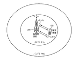
- FIG. 1 is a schematic diagram showing the concept of carrier aggregation.
- FIG. 1 illustrates an example in which communication is performed between the terminal device 100 and the base station device 200 using carrier aggregation. More specifically, from the base station apparatus 200 to the terminal apparatus 100, component components (Component Carrier; hereinafter referred to as “CC”) of two downlinks (Down Link; downlink, also referred to as “DL”). ), And data is transmitted from the terminal apparatus 100 to the base station apparatus 200 using component carriers (CC) of two uplinks (Up Link; uplink, hereinafter also referred to as “UL”). An example to be transmitted is shown. According to the 3GPP standard, the bandwidth of each component carrier is set to 20 MHz or less.
- Fig. 1 shows an example of FDD system. Show.
- FDD Frequency Division Duplex
- TDD Time Division Duplex
- component carriers are set in each of a plurality of discretely assigned frequency bands (band I and band II) instead of continuous frequency bands. That is, a downlink component carrier and an uplink component carrier are allocated in band I, and another downlink component carrier and an uplink component carrier are allocated in band II.
- the frequency band that can be used in this way is systematically defined according to the radio wave administration of each country. For example, 2 GHz band (uplink: 1920 MHz-1980 MHz / downlink: 2110 MHz-2170 MHz) is used as band I, and 800 MHz band (uplink: 824 MHz-849 MHz / downlink: 869 MHz-894 MHz) is used as band II. Is used.
- MIMO is a scheme in which a plurality of antennas are provided on each of the transmission side and the reception side, and transmission data is transmitted in parallel from the plurality of antennas. At this time, radio signals in the same frequency band (any band available in the system) are transmitted from the respective antennas at the same time.
- the number of antennas provided on the transmission side and the reception side is not necessarily the same, and a configuration in which M antennas are provided on the transmission side and N antennas are provided on the reception side can be employed. Such a configuration is also referred to as M ⁇ N MIMO.
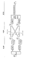
- FIG. 2 is a schematic diagram showing the concept of MIMO.
- FIG. 2 shows an example of 2 ⁇ 2 MIMO in which two antennas are provided on the transmission side and two antennas are provided on the reception side as a typical configuration.
- transmission data is divided according to the number of antennas (two in the example shown in FIG. 2), and the divided data (transmission symbols) are respectively transmitted to corresponding transmission units (transmission symbols).
- a plurality of radio signals (streams) respectively corresponding to the divided data are generated by modulation in the units 1 and 2). Then, the generated streams are transmitted in parallel from the corresponding antennas.
- radio signals (streams) from the respective antennas on the transmitting side are received in parallel by a plurality of antennas, and a propagation path for the radio signals (streams) received by the respective antennas Is output as received data by performing a matrix operation in accordance with the characteristics.
- the transmitted radio signals s1 and s2 can be estimated from the observed radio signals r1 and r2.
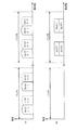
- FIG. 3 is a schematic diagram showing an allocation example of frequency bands used in the communication system according to the embodiment of the present invention.
- FIG. 3A shows a case where carrier aggregation is used
- FIG. 3B shows a case where MIMO is used.
- FIG. 3A shows an example in which component carriers are allocated in each of a plurality of discretely allocated frequency bands (band I and band II) as described above. That is, in band I, one or more downlink component carriers (DLCCI-1 / DLCCI-2) and one or more uplink component carriers (ULCCI-1 / ULCCI-2) are allocated, and in band II, 1 One or more downlink component carriers (DLCCII-1 / DLCCII-2) and one or more uplink component carriers (ULCCII-1 / ULCCII-2) are allocated.
- band I one or more downlink component carriers (DLCCI-1 / DLCCI-2) and one or more uplink component carriers (ULCCII-1 / ULCCII-2) are allocated, and in band II, 1
- DLCCII-1 / DLCCII-2 and one or more uplink component carriers (ULCCII-1 / ULCCII-2) are allocated.
- component carriers are allocated to different frequency bands in the frequency domain.
- FIG. 3B shows an example in which a plurality of streams are allocated in one of a plurality of discretely allocated frequency bands (band I and band II) as described above.
- a plurality of downlink streams (DLST1 and DLST2) and a plurality of uplink streams (ULST1 and ULST2) are allocated to a certain frequency band of Band II.
- a plurality of streams may be allocated to any frequency band of band I.
- the frequency bands to be assigned are different in carrier aggregation and MIMO. For this reason, if a dedicated circuit is installed in addition to the communication method in order to realize a terminal device compatible with both carrier aggregation and MIMO communication methods, the circuit scale inevitably increases. Further, since the transmission circuit includes a power amplifier for generating a wireless signal to be transmitted, it is conceivable that the power consumption increases as the number of power amplifiers increases.
- the radio communication system uses both a smaller number of transmission / reception circuits (particularly, power amplifiers), supports both carrier aggregation and MIMO, and depending on the communication situation, these communication methods.
- the purpose is to realize an appropriate throughput by appropriately switching the.
- the radio communication system according to the present embodiment includes a terminal device 100 and a base station device 200.
- Base station apparatus 200 is connected to core network 400 via core network apparatus 300.
- the terminal device 100 has a plurality of transmission units for generating radio signals and a plurality of reception units for receiving radio signals.
- the base station apparatus 200 also includes a plurality of transmission units for generating radio signals and a plurality of reception units for receiving radio signals. 4 and 5 exemplify a configuration in which each of terminal apparatus 100 and base station apparatus 200 has two transmission units and two reception units as typical examples, the number of transmission units and reception units. May be any as long as it is 2 or more. Further, it is not necessary to match the numbers of transmission units and reception units in terminal apparatus 100 and base station apparatus 200.
- the terminal device 100 has two systems of input from the antenna to the receiving unit, and when carrier aggregation is selected, the band I and the band II (see FIG. 3 (a)), at least one component carrier can be received, and when MIMO is selected, two downlink streams can be received.
- base station apparatus 200 has two systems of input from the antenna to the receiving unit.
- band I and band II see FIG. 3A.
- at least one component carrier can be received and two uplink streams can be received when MIMO is selected.
- the plurality of component carriers When a plurality of component carriers are assigned to the same frequency band (band), the plurality of component carriers may be mounted so as to be received by a single receiving unit.
- the control unit of the base station apparatus 200 generates a baseband signal by performing predetermined signal processing on transmission data (downlink) received from the core network apparatus 300 to the terminal apparatus 100.
- Each of the transmission units of the base station apparatus 200 modulates the baseband signal from the control unit into a radio signal (RF signal), and transmits the result to the terminal apparatus 100 via a corresponding antenna.
- Each receiving unit of the terminal device 100 demodulates a radio signal (RF signal) received via a corresponding antenna into a baseband signal and outputs the demodulated signal to the control unit.
- the control unit of the terminal device 100 acquires received data (downlink) by performing predetermined signal processing on the baseband signal received from each receiving unit.
- the control unit of the terminal apparatus 100 performs a predetermined signal process on the transmission data (uplink) to the base station apparatus 200 according to a user operation, etc. Generate.
- Each of the transmission units of the terminal device 100 modulates the baseband signal from the control unit into a radio signal (RF signal), and transmits the result to the base station device 200 via a corresponding antenna.
- Each receiving unit of the base station apparatus 200 demodulates a radio signal (RF signal) received via a corresponding antenna into a baseband signal and outputs it to the control unit.
- the control unit of the base station apparatus 200 acquires received data (uplink) by performing predetermined signal processing on the baseband signal received from each receiving unit.
- terminal apparatus 100 includes a plurality of transmission units for generating radio signals
- base station apparatus 200 also includes a plurality of transmission units for generating radio signals. Then, based on the communication information including the communication environment between the base station apparatus 200 and the terminal apparatus 100 and the requested amount of data, the plurality of transmission units / reception sections of the base station apparatus 200 and the plurality of terminal apparatuses 100 A communication method to be used is determined from a plurality of communication methods having different frequency allocation forms for the transmission unit / reception unit.
- FIG. 4 illustrates an example in which communication is performed between the base station apparatus 200 and the terminal apparatus 100 using two component carriers respectively assigned to the downlink and the uplink.
- a set of downlink component carriers DLCCI and DLCCII allocated to the downlink is also referred to as “DLCC set”
- a set of uplink component carriers ULCCI and ULCCII allocated to the uplink is also referred to as “ULCC set”. .
- the first transmission unit (transmission unit 1) among the transmission units of the base station apparatus 200 has the first frequency band (band I ) Radio signal (DLCCI) and the second transmission unit (transmission unit 2) of the transmission units of the base station apparatus 200 transmits the radio signal (DLCCII) in the second frequency band (band II).
- DLCCI Radio signal
- the second transmission unit (transmission unit 2) of the transmission units of the base station apparatus 200 transmits the radio signal (DLCCII) in the second frequency band (band II).
- the 1st transmission part (transmission part 1) among the transmission parts of the terminal device 100 transmits the radio signal (ULCCI) of a 1st frequency band (band I)
- the second transmitter (transmitter 1) transmits a radio signal (ULCCI) in the second frequency band (band II).
- the example shown in FIG. 5 shows an example in which communication is performed between the base station apparatus 200 and the terminal apparatus 100 using MIMO.
- the first and second transmission units (transmission units 1 and 2) of the base station apparatus 200 are respectively in the same frequency band.
- the 2nd radio signal (DLST1, DLST2) is transmitted.
- the first and second transmission units (transmission units 1 and 2) of the terminal device 100 transmit the first and second radio signals (ULST1 and ULST2), respectively.
- the demodulation method differs between carrier aggregation and MIMO, and therefore, on the receiving side, the demodulation method (signal processing) is appropriately switched according to the change of the communication method.
- carrier aggregation and MIMO (FIG. 5) are considered in consideration of specifications (for example, traffic amount) required for a communication path between base station apparatus 200 and terminal apparatus 100. ), A more suitable communication method is selected. Note that a normal communication method (corresponding to a state in which one component carrier is assigned to each of the downlink and uplink) that is neither carrier aggregation nor MIMO may be selected.
- the downlink and uplink channels are separated in the frequency domain, it is possible to select a different communication scheme between the downlink and the uplink. For example, data transmission may be performed using a plurality of component carriers for the downlink while data transmission is performed using a normal communication method (using one component carrier) for the uplink. Therefore, the determination as to which communication method to use as described above may be performed for the downlink and the uplink collectively, or may be performed individually.
- the function for determining the communication method as described above is provided by the cooperation of the terminal device 100 and the base station device 200.
- the function can be provided by either the terminal device 100 or the base station device 200 alone.
- the terminal device 100 can have such logic, and can be distributed in the base station device 200 and the terminal device 100 in a distributed manner.
- the base station apparatus 200 may determine the downlink communication scheme
- the terminal apparatus 100 may determine the uplink communication scheme.
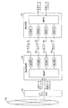
- FIG. 6 is a block diagram of terminal device 100 used in the communication system according to the embodiment of the present invention.
- terminal apparatus 100 includes a housing 150 provided with transmission antennas 142 and 144 for transmitting radio signals and reception antennas 146 and 148 for receiving radio signals.
- the casing 150 includes a central processing unit 110, a signal processing unit 130, transmission units 132 and 134, and reception units 136 and 138.
- the central processing unit 110 and the signal processing unit 130 correspond to the control unit illustrated in FIGS. 4 and 5.
- the central processing unit 110 includes, as main components, a processor, a nonvolatile memory for holding a program executed by the processor, and a volatile memory functioning as a work memory.
- the central processing unit 110 performs signal processing on reception data and transmission data in cooperation with the signal processing unit 130, and controls the carrier frequency used by the transmission units 132 and 134 and the reception units 136 and 138. Manages various types of control related to communications.
- central processing unit 110 includes logic that gives an internal command for changing the decoding method in signal processing unit 130 in response to an instruction to switch the communication method. These logics are typically provided by the central processing unit 110 executing a program. For example, modules corresponding to each logic are stored in advance in a nonvolatile memory, and the central processing unit 110 reads and executes these modules to provide functions as described later.
- the signal processing unit 130 processes a radio signal exchanged with the base station apparatus 200 that manages a cell range in which the own apparatus exists. More specifically, the signal processing unit 130 outputs transmission data to the base station apparatus 200 to the transmission units 132 and 134 in accordance with an internal command given from the central processing unit 110 or the like. More specifically, the signal processing unit 130 generates a radio signal to be transmitted by each of the transmission units 132 and 134 by performing signal processing on the transmission data in accordance with the selected communication method. Data for output.
- Transmitters 132 and 134 encode and modulate the data received from signal processor 130 and output the resulting radio signals to corresponding transmit antennas 142 and 144, respectively.
- Receiving sections 136 and 138 demodulate radio signals received via corresponding receiving antennas 146 and 148, and output the baseband signals obtained as a result to signal processing section 130.
- each of the transmission unit and the reception unit and the antenna are one-to-one is shown.
- the transmission units 132 and 134, the reception units 136 and 138, and the antenna A transmission antenna and a reception antenna may be shared by providing a duplexer between the two.
- a part or all of the functions provided by the central processing unit 110 may be implemented as dedicated hardware (integrated circuit).
- One chip may be used.
- SoC System On a Chip
- components such as a processor, a memory, and a controller for peripheral devices are integrated into one chip can be used.
- all or part of the functions provided by the signal processing unit 130, the transmission units 132 and 134, and the reception units 136 and 138 may be implemented as software.
- an arithmetic device such as a CPU (Central Processing Unit) or a DSP (Digital Signal Processor) executes a preinstalled instruction set.
- the casing 150 further includes a display unit 120 for displaying various types of information included in the reception data, a microphone 122 for acquiring user's voice included in the transmission data, and voice data included in the reception data.
- a speaker 124 for reproduction and an input unit 126 for accepting a user operation are included. These parts are typically arranged so as to be exposed from the housing 150.
- FIG. 7 is a block diagram of base station apparatus 200 used in the communication system according to the embodiment of the present invention.
- base station apparatus 200 includes central processing unit 210, signal processing unit 230, transmission units 232 and 234, transmission antennas 242 and 244, reception units 236 and 238, and reception antennas 246 and 246. 248, an upper network interface (I / F) 220, and a control interface (I / F) 224.
- the central processing unit 210 and the signal processing unit 230 correspond to the control units shown in FIGS.
- the central processing unit 210 includes, as main components, a processor, a nonvolatile memory for holding a program executed by the processor, and a volatile memory functioning as a work memory.
- the central processing unit 210 performs signal processing on reception data and transmission data in cooperation with the signal processing unit 230 and controls the carrier frequency used by the transmission units 232 and 234 and the reception units 236 and 238. Controls various types of communication.
- the central processing unit 210 includes a communication method selection logic 212.
- the communication method selection logic 212 is typically provided by the central processing unit 210 executing a program. For example, modules corresponding to each logic are stored in advance in a nonvolatile memory, and the central processing unit 210 reads and executes these modules to provide functions as described later.
- the communication method selection logic 212 is based on communication information including the communication environment between the base station device 200 and the terminal device 100 and the requested amount of data, and a plurality of transmission units of the base station device 200 and the terminal device 100.
- a communication method to be used is determined from among a plurality of communication methods having different frequency allocation forms for a plurality of transmission units.
- the communication method selection logic 212 executes processing for notifying the terminal device 100 of the determined communication method. Details of processing in the communication method selection logic 212 will be described later.
- the signal processing unit 230 processes a radio signal exchanged with the terminal device 100 within the cell range to be managed. More specifically, the signal processing unit 230 outputs transmission data to the terminal device 100 to the transmission units 232 and 234 in accordance with an internal command given from the central processing unit 210 or the like. More specifically, the signal processing unit 230 generates a radio signal to be transmitted by each of the transmission units 232 and 234 by performing signal processing on the transmission data according to the selected communication method. Data for output.
- Transmitters 232 and 234 perform encoding and modulation on the data received from signal processor 230 and output radio signals generated as a result to corresponding transmit antennas 242 and 244, respectively.
- Receiving units 236 and 238 demodulate radio signals received via corresponding receiving antennas 246 and 248, and output the resulting baseband signals to signal processing unit 230.
- the host network interface 222 exchanges user data, control information, management information, and the like with the core network device 300 that manages its own station. Similarly, the control interface 224 exchanges control information with other base station apparatuses 200.
- the communication environment between the base station apparatus 200 and the terminal apparatus 100 and the requested data are determined as to which of the normal communication system, carrier aggregation, and MIMO is set for communication. It is determined based on communication information including quantity. More specifically, communication path information between the base station apparatus 200 and the terminal apparatus 100, a communication status reported from the terminal apparatus 100, a communication traffic amount in the base station apparatus 200, and communication supported by the terminal apparatus 100 The communication method that can realize the optimum throughput is determined based on the method and the amount of data that the terminal device 100 requests to transmit.
- An example of communication path information between the base station apparatus 200 and the terminal apparatus 100 includes a free state of a resource block (RB).
- RB resource block
- An example of the communication status reported from the terminal device 100 includes a channel quality report (Channel Quality Indication: CQI) notified from the terminal device 100. Further, the communication status may include a radio signal strength, a bit error rate, and the like indicated as a reference signal reception strength (RSRP: Reference Signal Received Power) in each frequency band.
- CQI Channel Quality Indication
- RSRP Reference Signal Received Power
- An example of the amount of communication traffic in the base station device 200 includes the amount of data to be transmitted from the base station device 200 to the terminal device 100.
- Examples of communication methods supported by the terminal device 100 include the number of transmission units (power amplifiers) mounted on the terminal device 100 and the number of antennas.
- the base station apparatus 200 determines to switch the communication method in accordance with the determination criteria (1) to (3) described above, the base station apparatus 200 sends information about the switched communication method to the terminal apparatus 100.
- the terminal apparatus 100 Any means (channel) for transmitting such information to the terminal device 100 may be used.
- base station apparatus 200 (communication system selection logic 212) notifies terminal apparatus 100 of the selected communication system using any one of a broadcast channel, a downlink common channel, and a downlink dedicated channel.
- the terminal device 100 When the terminal device 100 receives the notification as described above from the base station device 200, the terminal device 100 receives the transmission units 132 and 134 according to the designated communication method (normal communication method, carrier aggregation, and MIMO) Settings for the units 136 and 138 and the signal processing unit 130 are changed.
- the designated communication method normal communication method, carrier aggregation, and MIMO
- the base station apparatus 200 determines each of the downlink and uplink according to the determined communication scheme after determining the communication scheme.
- Configure communication settings for That is, for the downlink, base station apparatus 200 sets the operations of transmitting sections 232 and 234 and transmits information for setting the operations of receiving sections 136 and 138 of terminal apparatus 100 to terminal apparatus 100.
- base station apparatus 200 sets the operations of receiving sections 236 and 238 and transmits information for setting the operations of transmitting sections 132 and 134 of terminal apparatus 100 to terminal apparatus 100.
- the terminal device 100 when the terminal device 100 has a main logic for selecting a communication method, when the terminal device 100 determines the communication method, the terminal device 100 performs communication settings for each of the downlink and the uplink according to the determined communication method. That is, for the downlink, the terminal device 100 sets the operations of the receiving units 136 and 138 and transmits information for setting the operations of the transmitting units 232 and 234 of the base station device 200 to the base station device 200. . For uplink, the terminal device 100 sets the operation of the transmission units 132 and 134 and transmits information for setting the operation of the reception units 236 and 238 of the base station device 200 to the base station device 200. .
- transmission capacity (frequency use quality) when carrier aggregation is selected and transmission capacity (space use quality) when MIMO is selected is dominant is, for example, frequency It can be evaluated on a two-dimensional coordinate indicating the relationship between usage quality and space usage quality.
- FIG. 8 is a diagram for describing a frequency / space use determination method in the communication system according to the embodiment of the present invention.
- the vertical axis represents the number of component carriers (frequency use)
- the horizontal axis represents the number of MIMO streams (space use).
- the frequency use quality (frequencies f1, f2) and the space use quality (streams ST1, ST2) the channel quality related to transmission data between the base station apparatus 200 and the terminal apparatus 100 is taken into consideration on the graph. Consider which position will maximize the overall throughput.
- the carrier aggregation is selected.
- MIMO is selected.
- FIG. 9 is a flowchart showing a processing procedure in base station apparatus 200 used in the communication system according to the embodiment of the present invention.
- the central processing unit 210 of the base station apparatus 200 determines whether data communication is requested with any one of the terminal apparatuses 100 (step S2). For example, when the central processing unit 210 receives data (downlink data) transmitted to the terminal device 100 from the core network device 300, the central processing unit 210 determines that data communication is requested. Alternatively, when receiving a request for data transmission (downlink data and uplink data) from terminal device 100, central processing unit 210 determines that data communication is requested.
- step S2 If it is determined that data communication is not requested (NO in step S2), the process ends.
- step S4 central processing unit 210 should be transmitted between base station apparatus 200 and terminal apparatus 100. It is determined whether or not the amount of data exceeds a predetermined value (step S4).
- This predetermined value is an index for evaluating whether or not it is necessary to perform communication at a high speed and a large capacity compared to a normal communication method.
- the terminal apparatus 100 notifies the base station apparatus 200 of the amount of data requested for transmission. Therefore, in step S4, the amount of data scheduled to be transmitted from base station apparatus 200 to terminal apparatus 100 and / or the amount of data scheduled to be transmitted from terminal apparatus 100 to base station apparatus 200 can be evaluated.
- central processing unit 210 When the amount of data to be transmitted between base station apparatus 200 and terminal apparatus 100 does not exceed a predetermined value (NO in step S4), central processing unit 210 performs communication at high speed and large capacity. It is considered that there is no need to carry out, and a normal communication method is selected, and an instruction indicating the selected communication method is output (if necessary) (step S6). That is, when the camp is already on any component carrier, the state is maintained and no special notification is made.
- step S4 when the amount of data to be transmitted between base station apparatus 200 and terminal apparatus 100 exceeds a predetermined value (YES in step S4), central processing unit 210 performs carrier aggregation. It is determined whether or not it is possible (step S8). More specifically, the central processing unit 210 determines whether or not a vacant space for assigning component carriers exists in the frequency band. That is, the central processing unit 210 evaluates the availability of radio resources.
- the central processing unit 210 determines whether or not the MIMO can be executed (step S10). More specifically, the central processing unit 210 determines whether both the terminal apparatus 100 and the base station apparatus 200 support MIMO. For this determination, information transmitted from the terminal device 100 is used. Here, when the MIMO cannot be executed (NO in step S10), central processing unit 210 determines that neither the carrier aggregation nor the MIMO can be executed. Then, the central processing unit 210 selects a normal communication method, and outputs an instruction indicating the selected communication method (if necessary) (step S6). Then, the communication method selection process ends, and the data transmission / reception process starts.
- central processing unit 210 selects MIMO as the communication method and outputs an instruction indicating that MIMO has been selected. (Step S12). Then, the communication method selection process ends, and the data transmission / reception process starts.
- the central processing unit 210 determines whether or not the MIMO can be executed (step S14). More specifically, the central processing unit 210 determines whether both the terminal apparatus 100 and the base station apparatus 200 support MIMO. When the execution of MIMO is impossible (NO in step S14), central processing unit 210 selects carrier aggregation as the communication method and outputs an instruction indicating that carrier aggregation has been selected. (Step S16). Then, the communication method selection process ends, and the data transmission / reception process starts.
- the central processing unit 210 will obtain the transmission capacity (frequency utilization quality) that would be obtained when using carrier aggregation. And the transmission capacity (space utilization quality) that would be obtained when using MIMO (step S18). Subsequently, the central processing unit 210 has a larger transmission capacity (frequency utilization quality) that would be obtained when carrier aggregation was used than a transmission capacity (space utilization quality) that would be obtained when MIMO was used. Whether or not (step S20).
- the central processing unit 210 selects carrier aggregation as the communication method, and outputs an instruction indicating that carrier aggregation has been selected (step S16). Then, the communication method selection process ends, and the data transmission / reception process starts.
- the central processing unit 210 selects MIMO as the communication method, and outputs an instruction indicating that the MIMO has been selected (step S12). Then, the communication method selection process ends, and the data transmission / reception process starts.
- FIG. 10 is a sequence diagram showing a processing procedure in base station apparatus 200 used in the communication system according to the embodiment of the present invention.
- terminal device 100 is in a standby state as an initial state (sequence SQ2).
- this initial state it is assumed that the terminal device 100 is camping on the downlink component carrier DLCCI set to the band I, for example.
- Terminal apparatus 100 establishes communication with base station apparatus 200 using uplink component carrier ULCCI corresponding to downlink component carrier DLCCI that is camping on in order to connect to base station apparatus 200 (sequence SQ6).
- uplink component carrier ULCCI is notified by broadcast information from the base station apparatus 200 to the terminal apparatus 100.
- the terminal device 100 uses the uplink component carrier ULCCI, in addition to a download request from a specific access destination, information on the source terminal device 100 (for example, to carrier aggregation / MIMO)
- a packet communication request including the availability, the number of antennas, and the number of power amplifiers (transmission circuits) is transmitted to base station apparatus 200 (sequence SQ8).
- base station apparatus 200 When receiving the packet communication request from terminal apparatus 100, base station apparatus 200 transmits a quality measurement request for each downlink component carrier DLCC to terminal apparatus 100 (sequence SQ10). Typically, this quality measurement request is notified to the terminal device 100 using any one of the broadcast channel, the downlink common channel, and the downlink dedicated channel. However, it may be notified using other notification means (channel).
- the terminal apparatus 100 When receiving the quality measurement request from the base station apparatus 200, the terminal apparatus 100 measures the quality of the downlink component carrier DLCC that is the target of the measurement request, and includes the channel quality including the quality level obtained by the measurement. Report (Channel Quality Indication: CQI) is notified to base station apparatus 200 (sequence SQ12).
- CQI Channel Quality Indication
- the base station apparatus 200 is used for (1) the amount of data to be transmitted between the base station apparatus 200 and the terminal apparatus 100, (2) the availability of radio resources, (3) the channel quality report from the terminal apparatus 100, etc. Based on this, the communication system determination process as shown in FIG. 9 is executed (sequence SQ14). That is, the base station apparatus 200 determines which of the normal communication scheme, carrier aggregation, and MIMO is used for communication.
- base station apparatus 200 selects carrier aggregation as the communication method ("CA" in sequence SQ14), information necessary for executing carrier aggregation, for example, DLCC set and ULCC set To decide. Then, base station apparatus 200 notifies terminal apparatus 100 of an instruction indicating that carrier aggregation has been selected including these pieces of information (sequence SQ16). The terminal device 100 changes the settings of the transmission units 132 and 134 and the reception units 136 and 138 in accordance with the DLCC set and ULCC set notified from the base station device 200. In addition, base station apparatus 200 changes the settings of transmission sections 232 and 234 and reception sections 236 and 238 according to the determined DLCC set and ULCC set. Then, base station apparatus 200 and terminal apparatus 100 start communication using carrier aggregation (sequence SQ18).
- CA carrier aggregation
- base station apparatus 200 determines information necessary for MIMO execution, such as the number of streams. Then, base station apparatus 200 notifies terminal apparatus 100 of an instruction indicating that MIMO has been selected, including these pieces of information (sequence SQ20). The terminal device 100 changes the settings of the transmission units 132 and 134 and the reception units 136 and 138 according to the information notified from the base station device 200. Moreover, the base station apparatus 200 changes the settings of the transmission units 232 and 234 and the reception units 236 and 238 according to MIMO. Base station apparatus 200 and terminal apparatus 100 start communication using MIMO (sequence SQ22).
- base station apparatus 200 when the normal communication method is selected ("normal" in sequence SQ14), base station apparatus 200 basically does not give a special notification. Therefore, base station apparatus 200 and terminal apparatus 100 start communication using the currently set component carrier (DLCCI in this example) (sequence SQ24).
- DLCCI currently set component carrier
- FIG. 9 and 10 show an example in which a communication method selection process is executed when an event such as a packet communication request occurs.
- the communication system can be switched as necessary. That is, while data communication is being performed between the base station apparatus 200 and the terminal apparatus 100 using carrier aggregation or MIMO, communication is performed based on a channel quality report from the terminal apparatus 100 or the like. Monitor quality at any time. Then, a communication method capable of realizing an optimum throughput is selected according to the communication method determination procedure as shown in FIG. When it is determined that the communication method needs to be switched, the communication method is switched by the same processing as described above.
- the common transmission circuit and reception circuit are used in any communication system, so that the circuit utilization efficiency can be increased.
- the circuit utilization efficiency can be increased.
- by sharing the circuit it is possible to avoid both an increase in circuit scale and an increase in power consumption, and a communication environment and a data amount requested to be transmitted.
- the optimum throughput can be realized by selecting a communication method according to the above.
- the radio communication system when it is determined that it is necessary to realize higher-speed and large-capacity data communication, either carrier aggregation or MIMO is selected and the base station apparatus Data communication between the terminal device and the terminal device. For this reason, it is possible to avoid unnecessarily occupying the frequency band and to realize a throughput according to the request.
- logic for selecting a communication method to be used may be arranged on the base station apparatus side or on the terminal apparatus side.
- a suitable structure can be employ
- the circuit configuration of the terminal device can be further simplified, so that the cost of the terminal device can be reduced.
- the wireless communication system according to the present embodiment is improved by improving a part of the base device in the conventional wireless communication system currently operated. Can be realized. In this case, the cost of the base station apparatus can be reduced.
- 100 terminal device 110, 210 central processing unit, 120 display unit, 122 microphone, 124 speaker, 126 input unit, 130, 230 signal processing unit, 132, 134, 232, 234 transmission unit, 136, 138, 236, 238 reception Unit, 142, 144, 242, 244, transmitting antenna, 146, 148, 246, 248, receiving antenna, 150 housing, 200 base station device, 212 communication method selection logic, 222 upper network interface, 224 control interface, 300 core network device 400 core network.
Landscapes
- Engineering & Computer Science (AREA)
- Computer Networks & Wireless Communication (AREA)
- Signal Processing (AREA)
- Computer Security & Cryptography (AREA)
- Mobile Radio Communication Systems (AREA)
Abstract
無線通信システムは、無線信号を生成するための送信部を複数含む基地局装置と、無線信号を生成するための送信部を複数含む端末装置と、基地局装置と端末装置との間の通信環境および要求されたデータ量を含む、通信情報に基づいて、基地局装置の複数の送信部および端末装置の複数の送信部に対する周波数の割当て形態が異なる複数の通信方式の中から使用すべき通信方式を決定する通信方式決定手段とを有する。
Description
本発明は、複数の通信方式を選択可能な無線通信システム、基地局装置、端末装置、および、無線通信方法に関する。
現在、3GPP(Third Generation Partnership Project)は、次世代通信方式である、LTE(Long Term Evolution:(第3世代の)長期進化)について仕様化を進めている。さらに、LTEを発展させた規格であるLTE-A(LTE-Advanced)についても仕様化の検討が行われている。
LTE-Aでは、LTEに比較してより高速かつ大容量の通信を実現することが要求されている。そのため、LTE-Aは、LTEに比較してより広帯域な周波数範囲をサポートすることとされている。現在までの検討によれば、LTEの最大送信帯域幅が20MHzであるのに対して、LTEの最大送信帯域幅を100MHzまで拡張されることとされている。
しかしながら、世界各国の電波利用状況を鑑みると、連続した広帯域の周波数範囲をLTE-A用として確保することは容易ではない。また、LTEとのバックワード・コンパチビリィティ(後方互換性)を可能な限り維持する必要もある。そこで、キャリア・アグリゲーション(Carrier aggregation)という無線通信技術の導入が検討されている。このキャリア・アグリゲーションでは、LTEの最大送信帯域幅である20MHzに相当するコンポーネントキャリアを複数まとめて利用することで、最大送信帯域幅を100MHzまで拡張する。これにより、基地局装置と端末装置との間で高速かつ大容量の通信を実現する。なお、このキャリア・アグリゲーションについては、3GPP RAN1#53b会合にて合意された(非特許文献1の5章参照)。
一方、高速かつ大容量の通信を実現する別の方法として、MIMO(Multiple-Input Multiple-Output)という、送信側および受信側の双方が複数のアンテナを組合せる無線通信技術が検討されている。このMIMOについては、LTEにおいて採用されるとともに、LTE-Aにおいても継続して検討されている(非特許文献1の6章および7章参照)。
MIMOにおいては、送信側は送信データを複数のデータ列(以下「ストリーム」とも称す。)に分け、それぞれのストリームを同一の周波数帯域の無線信号に変調するとともに、複数のアンテナを使用してそれぞれを受信側へ並列的に送信する。受信側では、複数のアンテナを用いて複数の無線信号を同時に受信するとともに、伝搬路の特性に応じた行列演算を行うことで、送信されたデータを復元する。このように、MIMOでは、同一の周波数帯域を利用して複数の信号を並列的に送信するので、通信速度を向上させても、キャリア・アグリゲーションとは異なり、占有する周波数帯域は増加しない。但し、MIMOを利用することで、アンテナや増幅器などを含む物理的な送受信回路がより多く必要となる。
3GPP Organizational Partners,"3rd Generation Partnership Project;Technical Specification Group Radio Access Network;Evolved Universal Terrestrial Radio Access (E-UTRA);Further advancements for E-UTRA physical layer aspects (Release 9)",3GPP TS 36.814 V9.0.0 (2010-03),Section 5,6 and 7
将来のLTE-A方式に対応した端末装置を考慮した場合、上述のような技術背景に従えば、キャリア・アグリゲーションおよびMIMOの両方の通信方式に対応した端末装置を実現する必要があると予想される。
しかしながら、現時点では、キャリア・アグリゲーションおよびMIMOの両方の通信方式に対応した端末装置についての具体的な構成やクラス規定については、規格上、明確にはなっていない。
そこで、本発明は、かかる問題を解決するためになされたものであり、その目的は、複数の通信方式を選択可能な無線通信システムにおいて、通信方式を適切に選択して通信を行うことのできる無線通信システム、基地局装置、端末装置、および、無線通信方法を提供することである。
本発明のある局面に従う無線通信システムは、無線信号を生成するための送信部を複数含む基地局装置と、無線信号を生成するための送信部を複数含む端末装置と、基地局装置と端末装置との間の通信環境および要求されたデータ量を含む、通信情報に基づいて、基地局装置の複数の送信部および端末装置の複数の送信部に対する周波数の割当て形態が異なる複数の通信方式の中から使用すべき通信方式を決定する通信方式決定手段とを有する。
好ましくは、通信方式決定手段は、基地局装置の送信部のうち第1の送信部が第1の周波数帯域の無線信号を送信するとともに、基地局装置の送信部のうち第2の送信部が第2の周波数帯域の無線信号を送信する第1の通信方式と、同一の周波数帯域において、第1および第2の送信部がそれぞれ第1および第2の無線信号を送信する第2の通信方式との間で、通信方式を選択する。
あるいは好ましくは、通信方式決定手段は、端末装置の送信部のうち第1の送信部が第1の周波数帯域の無線信号を送信するとともに、端末装置の送信部のうち第2の送信部が第2の周波数帯域の無線信号を送信する第1の通信方式と、同一の周波数帯域において、第1および第2の送信部がそれぞれ第1および第2の無線信号を送信する第2の通信方式との間で、通信方式を選択する。
あるいは好ましくは、通信方式決定手段は、基地局装置の送信部および端末装置の送信部に対して、キャリア・アグリゲーション方式およびMIMO(Multiple-Input Multiple-Output)方式のいずれかを設定する。
好ましくは、通信方式決定手段は、さらに、端末装置のチャネル品質報告に基づいて、通信方式を決定する。
好ましくは、通信方式決定手段は、端末装置の接続要求に応答して、通信方式を決定する。
さらに好ましくは、接続要求は、端末装置がサポートしている通信方式の情報、および、送信を要求するデータ量の少なくとも一方を含む。
好ましくは、通信方式決定手段は、選択した通信方式を、報知チャネル、下り共通チャネル、下り個別チャネルのいずれか1つを用いて、基地局装置から端末装置へ通知する。
この発明の別の局面に従えば、無線信号を生成するための送信部を複数含む端末装置と通信可能な基地局装置を提供する。基地局装置は、無線信号を受信するための複数の受信部と、基地局装置と端末装置との間の通信環境および要求されたデータ量を含む、通信情報に基づいて、複数の送信部および複数の受信部に対する周波数の割当て形態が異なる複数の通信方式の中から使用すべき通信方式を決定する通信方式決定手段と、決定された通信方式に従って、複数の送信部の動作を設定するための情報を端末装置へ送信するとともに、複数の受信部の動作を設定する設定手段とを含む。
この発明のさらに別の局面に従えば、無線信号を受信するための受信部を複数含む端末装置と通信可能な基地局装置を提供する。無線信号を生成するための複数の送信部と、基地局装置と端末装置との間の通信環境および要求されたデータ量を含む、通信情報に基づいて、複数の送信部および複数の受信部に対する周波数の割当て形態が異なる複数の通信方式の中から使用すべき通信方式を決定する通信方式決定手段と、決定された通信方式に従って、複数の受信部の動作を設定するための情報を端末装置へ送信するとともに、複数の送信部の動作を設定する設定手段とを含む。
この発明のさらに別の局面に従えば、無線信号を受信するための受信部を複数含む基地局装置と通信可能な端末装置を提供する。端末装置は、無線信号を生成するための複数の送信部と、基地局装置と端末装置との間の通信環境および要求されたデータ量を含む、通信情報に基づいて、複数の送信部および複数の受信部に対する周波数の割当て形態が異なる複数の通信方式の中から使用すべき通信方式を決定する通信方式決定手段と、決定された通信方式に従って、複数の受信部の動作を設定するための情報を基地局装置へ送信するとともに、複数の送信部の動作を設定する設定手段とを含む。
この発明のさらに別の局面に従えば、無線信号を生成するための送信部を複数含む基地局装置と通信可能な端末装置を提供する。端末装置は、無線信号を受信するための複数の受信部と、基地局装置と端末装置との間の通信環境および要求されたデータ量を含む、通信情報に基づいて、複数の送信部および複数の受信部に対する周波数の割当て形態が異なる複数の通信方式の中から使用すべき通信方式を決定する通信方式決定手段と、決定された通信方式に従って、複数の送信部の動作を設定するための情報を基地局装置へ送信するとともに、複数の受信部の動作を設定する設定手段とを含む。
この発明のさらに別の局面に従えば、基地局装置と端末装置との間での無線通信方法を提供する。ここで、基地局装置および端末装置の各々は、無線信号を生成するための送信部を複数含む。無線通信方法は、基地局装置と端末装置との間の通信環境および要求されたデータ量を含む、通信情報を取得するステップと、基地局装置の複数の送信部および端末装置の複数の送信部に対する周波数の割当て形態が異なる複数の通信方式の中から使用すべき通信方式を決定するステップと、決定された通信方式に従って、基地局装置の複数の送信部の動作を設定するステップと、決定された通信方式に従って、端末装置の複数の送信部の動作を設定するステップとを含む。
本発明によれば、複数の通信方式を選択可能な無線通信システムにおいて、通信方式を適切に選択して通信を行うことができる。
本発明の実施の形態について、図面を参照しながら詳細に説明する。なお、図中の同一または相当部分については、同一符号を付してその説明は繰返さない。
<1.概要>
本実施の形態に従う無線通信システムは、複数の通信方式(典型的には、キャリア・アグリゲーションとMIMO)を適切に選択することで、要求されるデータ量に応じて適切なスループットを実現することを目的としている。このように複数の通信方式を選択するために、各通信方式に対応する専用回路を端末装置に実装するような構成も想定されるが、互いに独立した専用回路を実装すると、回路規模が大きくなってしまい、また、消費電力が不要に増加するといった課題が生じ得る。
本実施の形態に従う無線通信システムは、複数の通信方式(典型的には、キャリア・アグリゲーションとMIMO)を適切に選択することで、要求されるデータ量に応じて適切なスループットを実現することを目的としている。このように複数の通信方式を選択するために、各通信方式に対応する専用回路を端末装置に実装するような構成も想定されるが、互いに独立した専用回路を実装すると、回路規模が大きくなってしまい、また、消費電力が不要に増加するといった課題が生じ得る。
そこで、本実施の形態に従う無線通信システムにおいては、共通の回路を採用するとともに、選択された通信方式に応じて、回路の動作を適切に設定することで、回路規模の拡大や消費電力の増大といった事態を生じることなく、基地局装置と端末装置との間で適切なスループットを実現する。
<2.キャリア・アグリゲーション>
まず、図1を参照して、キャリア・アグリゲーションについて説明する。図1は、キャリア・アグリゲーションの概念を示す模式図である。図1には、一例として、端末装置100と基地局装置200との間でキャリア・アグリゲーションを利用して通信が行われている一例を示す。より具体的には、基地局装置200から端末装置100へは、2つのダウンリンク(Down Link;下り回線、以下「DL」とも記す。)のコンポーネントキャリア(Component Carrier;以下「CC」とも記す。)を用いてデータが送信され、端末装置100から基地局装置200へは、2つのアップリンク(Up Link;上り回線、以下「UL」とも記す。)のコンポーネントキャリア(CC)を用いてデータが送信される例が示される。3GPPの規格によれば、各コンポーネントキャリアの帯域幅は、20MHz以下に設定される。
まず、図1を参照して、キャリア・アグリゲーションについて説明する。図1は、キャリア・アグリゲーションの概念を示す模式図である。図1には、一例として、端末装置100と基地局装置200との間でキャリア・アグリゲーションを利用して通信が行われている一例を示す。より具体的には、基地局装置200から端末装置100へは、2つのダウンリンク(Down Link;下り回線、以下「DL」とも記す。)のコンポーネントキャリア(Component Carrier;以下「CC」とも記す。)を用いてデータが送信され、端末装置100から基地局装置200へは、2つのアップリンク(Up Link;上り回線、以下「UL」とも記す。)のコンポーネントキャリア(CC)を用いてデータが送信される例が示される。3GPPの規格によれば、各コンポーネントキャリアの帯域幅は、20MHz以下に設定される。
LTEおよびLTE-Aでは、周波数分割多重(Frequency Division Duplex:FDD)方式および時間分割多重(Time Division Duplex:TDD)方式をサポートすることになっているが、図1には、FDD方式の例を示す。FDD方式を採用した場合には、ダウンリンクコンポーネントキャリアおよびアップリンクコンポーネントキャリアに対して、それぞれ異なる周波数が割当てられる。すなわち、ダウンリンク(基地局装置200から端末装置100)でのデータ送信およびアップリンク(端末装置100から基地局装置200)でのデータ送信のデータ送信は、互いに異なる周波数の無線信号を用いて行われる。
また、図1には、連続した周波数帯域ではなく、離散的に割当てられた複数の周波数帯域(バンドIおよびバンドII)のそれぞれにおいて、コンポーネントキャリアが設定される。すなわち、バンドIにおいて、ダウンリンクコンポーネントキャリアおよびアップリンクコンポーネントキャリアが割当てられるとともに、バンドIIにおいて、別のダウンリンクコンポーネントキャリアおよびアップリンクコンポーネントキャリアが割当てられる。
このように利用可能な周波数帯域は、各国の電波行政などに従ってシステム的に規定される。例えば、バンドIとしては、2GHz帯(アップリンク:1920MHz-1980MHz/ダウンリンク:2110MHz-2170MHz)が用いられ、バンドIIとしては、800MHz帯(アップリンク:824MHz-849MHz/ダウンリンク:869MHz-894MHz)が用いられる。
なお、周波数に応じて無線信号の伝搬特性や減衰特性は異なるので、上述のような互いに異なる複数の周波数帯域を用いた場合には、同一の基地局装置200がカバーするセル範囲も異なったものとなり得る(図1に示す「バンドIセル」と「バンドIIセル」)。
<3.MIMO>
次に、図2を参照して、MIMOについて説明する。MIMOは、送信側および受信側にそれぞれ複数のアンテナを設けて、送信データを複数のアンテナから並列的に伝送するという方式である。このとき、それぞれのアンテナからは、同一の周波数帯域(システムで利用可能ないずれかのバンド)の無線信号が同一時間に送信される。なお、送信側および受信側に設けるアンテナの数は同数である必要はなく、送信側にM本のアンテナを設け、受信側にN本のアンテナを設けるような構成を採用することができる。このような構成をM×NのMIMOとも称する。
次に、図2を参照して、MIMOについて説明する。MIMOは、送信側および受信側にそれぞれ複数のアンテナを設けて、送信データを複数のアンテナから並列的に伝送するという方式である。このとき、それぞれのアンテナからは、同一の周波数帯域(システムで利用可能ないずれかのバンド)の無線信号が同一時間に送信される。なお、送信側および受信側に設けるアンテナの数は同数である必要はなく、送信側にM本のアンテナを設け、受信側にN本のアンテナを設けるような構成を採用することができる。このような構成をM×NのMIMOとも称する。
図2は、MIMOの概念を示す模式図である。図2には、典型的な構成として、送信側に2本のアンテナを設けるとともに、受信側に2本のアンテナを設けた2×2MIMOの例を示す。
図2に示すように、送信側では、送信データをアンテナの数(図2に示す例では2本)に応じて分割するとともに、それぞれ分割されたデータ(送信シンボル)を対応する送信部(送信部1および2)において変調することで、分割されたデータにそれぞれ対応する複数の無線信号(ストリーム)を生成する。そして、この生成されたストリームを対応するアンテナからそれぞれ並列に送信する。
これに対して、受信側では、送信側のそれぞれのアンテナからの無線信号(ストリーム)を複数のアンテナで並列に受信するとともに、それぞれのアンテナで受信された無線信号(ストリーム)に対して伝搬路の特性に応じた行列演算を行うことで、受信データとして出力する。
この行列演算について説明すると、送信側において、送信アンテナTx1から無線信号s1が送信され、送信アンテナTx2から無線信号s2が送信されたとする。一方、受信側において、受信アンテナRx1で無線信号r1が受信され、受信アンテナRx2で無線信号r2が受信されたとする。このとき、送信アンテナTxiから受信アンテナTxjへの伝搬路の特性をhijとして表すと、以下のような行列式が成り立つ。

この行列式に基づいて、観測される無線信号r1およびr2から、送信された無線信号s1およびs2を推定することができる。
<4.通信システムの構成>
次に、本実施の形態に従う通信システムの構成について説明する。
次に、本実施の形態に従う通信システムの構成について説明する。
上述したように、キャリア・アグリゲーションおよびMIMOでは、使用する周波数帯域が異なったものとなる。図3は、本発明の実施の形態に従う通信システムにおいて使用される周波数帯域の割当て例を示す模式図である。ここで、図3(a)には、キャリア・アグリゲーションを利用する場合を示し、図3(b)には、MIMOを利用する場合を示す。
図3(a)に示すように、キャリア・アグリゲーションを用いる場合には、ダウンリンクおよびアップリンクの少なくとも一方において、複数のコンポーネントキャリアが割当てられる。図3(a)には、上述したような、離散的に割当てられた複数の周波数帯域(バンドIおよびバンドII)のそれぞれにおいて、コンポーネントキャリアが割当てられる例を示す。すなわち、バンドIにおいて、1つ以上のダウンリンクコンポーネントキャリア(DLCCI-1/DLCCI-2)および1つ以上のアップリンクコンポーネントキャリア(ULCCI-1/ULCCI-2)が割当てられ、バンドIIにおいて、1つ以上のダウンリンクコンポーネントキャリア(DLCCII-1/DLCCII-2)および1つ以上のアップリンクコンポーネントキャリア(ULCCII-1/ULCCII-2)が割当てられる。
そのため、周波数領域においては、それぞれ異なる周波数帯域にコンポーネントキャリアが割当てられることになる。
これに対して、図3(b)に示すように、MIMOを用いる場合には、同一の周波数帯域に複数のストリームを割当てることになる。図3(b)には、上述したような、離散的に割当てられた複数の周波数帯域(バンドIおよびバンドII)のうち一方において、複数のストリームが割当てられる例を示す。一例として、バンドIIのある周波数帯域に、複数のダウンリンクストリーム(DLST1およびDLST2)ならびに複数のアップリンクストリーム(ULST1およびULST2)が割当てられる。なお、バンドIのいずれかの周波数帯域に複数のストリームを割当ててもよい。
図3に示すように、キャリア・アグリゲーションおよびMIMOでは、割当てられる周波数帯域が異なったものとなる。そのため、キャリア・アグリゲーションおよびMIMOの両方の通信方式に対応した端末装置を実現しようとして、通信方式の別に専用回路を搭載すると、必然的に回路規模が大きくなってしまう。また、送信用の信回路には、送出さえる無線信号を生成するためのパワーアンプが含まれるので、このパワーアンプの数が増えることにより、消費電力が増大してしまうことが考えられる。
そこで、本実施の形態に従う無線通信システムは、より少ない数の送受信回路(特に、パワーアンプ)を用いて、キャリア・アグリゲーションおよびMIMOの両方に対応するとともに、通信状況に応じて、これらの通信方式を適宜切換えることにより、適切なスループットを実現することを目的としている。
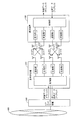
図4および図5は、本実施の形態に従う無線通信システムの構成を示す模式図である。図4および図5に示すように、本実施の形態に従う無線通信システムは、端末装置100と基地局装置200とを含む。基地局装置200は、コアネットワーク装置300を介してコアネットワーク400に接続される。
端末装置100は、無線信号を生成するための送信部を複数有しており、かつ、無線信号を受信するための受信部を複数有している。基地局装置200についても、無線信号を生成するための送信部を複数有しており、かつ、無線信号を受信するための受信部を複数有している。なお、図4および図5には、典型例として、端末装置100および基地局装置200の各々が、2つの送信部および2つの受信部を有する構成を例示するが、送信部および受信部の数は、2以上であれば、いずれであってもよい。また、端末装置100および基地局装置200における送信部および受信部の数を互いに一致させる必要もない。
このような構成を採用した場合には、端末装置100は、アンテナから受信部への2系統の入力を有することになり、キャリア・アグリゲーションが選択された場合には、バンドIおよびバンドII(図3(a)参照)において、それぞれ少なくとも1つのコンポーネントキャリアを受信できるとともに、MIMOが選択された場合には、2つのダウンリンクストリームを受信できる構成となっている。
同様に、基地局装置200は、アンテナから受信部への2系統の入力を有することになり、キャリア・アグリゲーションが選択された場合には、バンドIおよびバンドII(図3(a)参照)において、それぞれ少なくとも1つのコンポーネントキャリアを受信できるとともに、MIMOが選択された場合には、2つのアップリンクストリームを受信できる構成となっている。
なお、同一の周波数帯域(バンド)に対して複数のコンポーネントキャリアが割当てられる場合には、これらの複数のコンポーネントキャリアを単一の受信部で受信するように実装してもよい。
ダウンリンクについて見ると、基地局装置200の制御部は、コアネットワーク装置300から受取った端末装置100への送信データ(ダウンリンク)に対して所定の信号処理を行うことで、ベースバンド信号を生成する。基地局装置200の送信部の各々は、制御部からのベースバンド信号を無線信号(RF信号)に変調した上で、対応するアンテナを介して端末装置100へ送信する。端末装置100のそれぞれの受信部は、対応するアンテナを介して受信した無線信号(RF信号)をベースバンド信号に復調して制御部へ出力する。端末装置100の制御部は、それぞれの受信部から受取ったベースバンド信号に対して所定の信号処理を行うことで、受信データ(ダウンリンク)を取得する。
一方、アップリンクについて見ると、端末装置100の制御部は、ユーザ操作などに応じた基地局装置200への送信データ(アップリンク)に対して所定の信号処理を行うことで、ベースバンド信号を生成する。端末装置100の送信部の各々は、制御部からのベースバンド信号を無線信号(RF信号)に変調した上で、対応するアンテナを介して基地局装置200へ送信する。基地局装置200のそれぞれの受信部は、対応するアンテナを介して受信した無線信号(RF信号)をベースバンド信号に復調して制御部へ出力する。基地局装置200の制御部は、それぞれの受信部から受取ったベースバンド信号に対して所定の信号処理を行うことで、受信データ(アップリンク)を取得する。
図4および図5に示すように、端末装置100は、無線信号を生成するための送信部を複数含み、基地局装置200についても、無線信号を生成するための送信部を複数含む。そして、基地局装置200と端末装置100との間の通信環境および要求されたデータ量を含む、通信情報に基づいて、基地局装置200の複数の送信部/受信部および端末装置100の複数の送信部/受信部に対する周波数の割当て形態が異なる複数の通信方式の中から使用すべき通信方式が決定される。
図4に示す例では、基地局装置200と端末装置100との間で、ダウンリンクおよびアップリンクに対して割当てられたそれぞれ2つのコンポーネントキャリアを用いて通信が行われる場合の例を示す。なお、以下では、ダウンリンクに割当てられたダウンリンクコンポーネントキャリアDLCCIおよびDLCCIIの集合を「DLCCセット」とも称し、アップリンクに割当てられたアップリンクコンポーネントキャリアULCCIおよびULCCIIの集合を「ULCCセット」とも称する。
すなわち、図4に示すキャリア・アグリゲーションが選択された場合には、ダウンリンクとしては、基地局装置200の送信部のうち第1の送信部(送信部1)が第1の周波数帯域(バンドI)の無線信号(DLCCI)を送信するとともに、基地局装置200の送信部のうち第2の送信部(送信部2)が第2の周波数帯域(バンドII)の無線信号(DLCCII)を送信することになる。また、アップリンクとしては、端末装置100の送信部のうち第1の送信部(送信部1)が第1の周波数帯域(バンドI)の無線信号(ULCCI)を送信するとともに、端末装置100の送信部のうち第2の送信部(送信部1)が第2の周波数帯域(バンドII)の無線信号(ULCCI)を送信する。
一方、図5に示す例では、基地局装置200と端末装置100との間で、MIMOを利用して通信が行われる場合の例を示す。
すなわち、図5に示すMIMOが選択された場合には、ダウンリンクとしては、同一の周波数帯域において、基地局装置200の第1および第2の送信部(送信部1,2)がそれぞれ第1および第2の無線信号(DLST1,DLST2)を送信する。また、アップリンクとして、同一の周波数帯域において、端末装置100の第1および第2の送信部(送信部1,2)がそれぞれ第1および第2の無線信号(ULST1,ULST2)を送信する。
なお、キャリア・アグリゲーションおよびMIMOの間では復調方式(信号処理)が異なるので、受信側では、通信方式の変更に従って、復調方式(信号処理)についても適宜切換えられる。
典型的には、基地局装置200と端末装置100との間の通信経路に対して要求されるスペック(例えば、トラフィック量)などが考慮されて、キャリア・アグリゲーション(図4)およびMIMO(図5)のうち、より適した通信方式が選択される。なお、キャリア・アグリゲーションおよびMIMOのいずれでもない、通常の通信方式(ダウンリンクおよびアップリンクに対してそれぞれ1つのコンポーネントキャリアが割当てられている状態に相当)が選択される場合もある。
また、FDD方式を採用しているシステムにおいては、ダウンリンクおよびアップリンクのチャネルが周波数領域において分離されているので、ダウンリンクおよびアップリンクの間で異なる通信方式を選択することもできる。例えば、アップリンクについては通常の通信方式(1つのコンポーネントキャリアを使用)でデータ伝送を行う一方で、ダウンリンクについては複数のコンポーネントキャリアを使用してデータ伝送を行うようにしてもよい。そのため、上述したような、いずれの通信方式の使用するかについての判断は、ダウンリンクおよびアップリンクをまとめて行うようにしてもよいし、それぞれを単独で行うようにしてもよい。
上述のような、通信方式を判断する機能については、端末装置100および基地局装置200が協働することで提供される。あるいは、端末装置100および基地局装置200のいずれか単独で当該機能を提供することもできる。
以下では、典型的な実施の形態として、通信方式を選択する主たるロジックが基地局装置200に存在する構成例について説明する。しかしながら、端末装置100にこのようなロジックを持たせることもできるし、基地局装置200と端末装置100とに分散的に配置することもできる。例えば、基地局装置200がダウンリンクの通信方式について判断し、端末装置100がアップリンクの通信方式について判断するようにしてもよい。
<5.端末装置の構成>
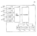
次に、本発明の実施の形態に従う通信システムにおいて利用される端末装置100の構成について説明する。図6は、本発明の実施の形態に従う通信システムにおいて利用される端末装置100のブロック図である。
次に、本発明の実施の形態に従う通信システムにおいて利用される端末装置100の構成について説明する。図6は、本発明の実施の形態に従う通信システムにおいて利用される端末装置100のブロック図である。
図6を参照して、端末装置100は、無線信号を送信するための送信アンテナ142,144と無線信号を受信するための受信アンテナ146,148とが設けられた筐体150を含む。筐体150は、中央処理部110と、信号処理部130と、送信部132,134と、受信部136,138とを含む。なお、中央処理部110および信号処理部130が図4および図5に示す制御部に相当する。
中央処理部110は、主たる構成要素として、プロセッサと、プロセッサで実行されるプログラムを保持するための不揮発性メモリと、ワークメモリとして機能する揮発性メモリとを含む。中央処理部110は、信号処理部130と連係して受信データおよび送信データに対する信号処理を行うとともに、送信部132,134および受信部136,138が使用するキャリア周波数の制御といった、端末装置100の通信に関する各種の制御を司る。さらに、中央処理部110は、通信方式の切換えが指示されたことに応答して、信号処理部130での復号方式を変更するための内部指令を与えるロジックなどを含む。これらのロジックは、典型的には、中央処理部110がプログラムを実行することで提供される。例えば、各ロジックに対応するモジュールが予め不揮発性メモリに記憶されており、中央処理部110がこれらのモジュールを読出して実行することで後述するような機能が提供される。
信号処理部130は、自装置が存在するセル範囲を管理する基地局装置200との間で遣り取りされる無線信号を処理する。より具体的には、信号処理部130は、中央処理部110などから与えられる内部指令に従って、基地局装置200への送信データを送信部132,134へ出力する。より具体的には、信号処理部130は、送信データに対して、選択されている通信方式に応じた信号処理を行うことで、送信部132および134のそれぞれが送信すべき無線信号を生成するためのデータを出力する。
送信部132および134は、信号処理部130から受けたデータに対して符号化および変調を行って、その結果生成される無線信号を対応する送信アンテナ142および144へそれぞれ出力する。
受信部136および138は、対応する受信アンテナ146および148を介して受信した無線信号を復調し、その結果得られたベースバンド信号を信号処理部130へ出力する。
図6に示す例では、理解を容易化するために、送信部および受信部の各々とアンテナとが一対一になっている構成を示すが、送信部132,134および受信部136,138とアンテナとの間にデュプレクサを設けることで、送信アンテナと受信アンテナとを共通化してもよい。
中央処理部110によって提供される機能の一部または全部を専用のハードウェア(集積回路)として実装してもよい。この場合には、中央処理部110によって提供される機能に加えて、信号処理部130、送信部132,134、および、受信部136,138によって提供される機能の全部または一部を含めて、1チップ化してもよい。さらに、プロセッサ、メモリ、周辺デバイス用のコントローラといった部品を1チップ化したSoC(System On a Chip)を利用することもできる。
代替の構成として、信号処理部130、送信部132,134、および受信部136,138によって提供される機能の全部または一部をソフトウェアとして実装してもよい。この場合には、CPU(Central Processing Unit)やDSP(Digital Signal Processor)といった演算装置(プロセッサ)が予めインストールされた命令セットを実行することになる。
筐体150は、さらに、受信データに含まれる各種情報を表示するための表示部120と、送信データに含まれるユーザの音声などを取得するためのマイク122と、受信データに含まれる音声データを再生するためのスピーカ124と、ユーザ操作を受付けるための入力部126とを含む。これらの部位は、典型的には、筐体150から露出するように配置される。
<6.基地局装置の構成>
次に、本発明の実施の形態に従う通信システムにおいて利用される基地局装置200の構成について説明する。図7は、本発明の実施の形態に従う通信システムにおいて利用される基地局装置200のブロック図である。
次に、本発明の実施の形態に従う通信システムにおいて利用される基地局装置200の構成について説明する。図7は、本発明の実施の形態に従う通信システムにおいて利用される基地局装置200のブロック図である。
図7を参照して、基地局装置200は、中央処理部210と、信号処理部230と、送信部232,234と、送信アンテナ242,244と、受信部236,238と、受信アンテナ246,248と、上位ネットワークインターフェイス(I/F)220と、制御インターフェイス(I/F)224とを含む。なお、中央処理部210および信号処理部230が図4および図5に示す制御部に相当する。
中央処理部210は、主たる構成要素として、プロセッサと、プロセッサで実行されるプログラムを保持するための不揮発性メモリと、ワークメモリとして機能する揮発性メモリとを含む。中央処理部210は、信号処理部230と連係して受信データおよび送信データに対する信号処理を行うとともに、送信部232,234および受信部236,238が使用するキャリア周波数の制御といった、基地局装置200の通信に関する各種の制御を司る。さらに、中央処理部210は、通信方式選択ロジック212を含む。この通信方式選択ロジック212は、典型的には、中央処理部210がプログラムを実行することで提供される。例えば、各ロジックに対応するモジュールが予め不揮発性メモリに記憶されており、中央処理部210がこれらのモジュールを読出して実行することで後述するような機能が提供される。
通信方式選択ロジック212は、基地局装置200と端末装置100との間の通信環境および要求されたデータ量を含む、通信情報に基づいて、基地局装置200の複数の送信部および端末装置100の複数の送信部に対する周波数の割当て形態が異なる複数の通信方式の中から使用すべき通信方式が決定する。また、通信方式選択ロジック212は、決定した通信方式を端末装置100へ通知するといった処理も実行する。この通信方式選択ロジック212における処理の詳細については、後述する。
信号処理部230は、管理するセル範囲内の端末装置100との間で遣り取りされる無線信号を処理する。より具体的には、信号処理部230は、中央処理部210などから与えられる内部指令に従って、端末装置100への送信データを送信部232,234へ出力する。より具体的には、信号処理部230は、送信データに対して、選択されている通信方式に応じた信号処理を行うことで、送信部232および234のそれぞれが送信すべき無線信号を生成するためのデータを出力する。
送信部232および234は、信号処理部230から受けたデータに対して符号化および変調を行って、その結果生成される無線信号を対応する送信アンテナ242および244へそれぞれ出力する。
受信部236および238は、対応する受信アンテナ246および248を介して受信した無線信号を復調し、その結果得られたベースバンド信号を信号処理部230へ出力する。
上位ネットワークインターフェイス222は、自局を管理するコアネットワーク装置300との間でユーザデータ、制御情報、および管理情報などを遣り取りする。同様に、制御インターフェイス224は、他の基地局装置200との間で制御情報を遣り取りする。
<7.処理ロジック>
次に、通信方式選択ロジックの処理ロジックについて説明する。
次に、通信方式選択ロジックの処理ロジックについて説明する。
上述したように、通常の通信方式、キャリア・アグリゲーション、MIMOのいずれの通信方式を設定して通信を行うのかについては、基地局装置200と端末装置100との間の通信環境および要求されたデータ量を含む、通信情報に基づいて判断される。より具体的には、基地局装置200と端末装置100との間の通信経路情報、端末装置100から報告される通信状況、基地局装置200における通信トラフィック量、端末装置100がサポートしている通信方式、端末装置100が送信を要求するデータ量などに基づいて、最適なスループットを実現できる通信方式が判断される。
基地局装置200と端末装置100との間の通信経路情報の一例としては、リソースブロック(Resource Block:RB)の空き状態などが含まれる。
端末装置100から報告される通信状況の一例としては、端末装置100から通知されるチャネル品質報告(Channel Quality Indication:CQI)などが含まれる。さらに、この通信状況には、各周波数帯におけるリファレンスシグナル受信強度(RSRP:Reference Signal Received Power)として示される無線信号の強度やビットエラーレートなどを含めてもよい。
基地局装置200における通信トラフィック量の一例としては、基地局装置200から端末装置100へ送信しようとしているデータの量などが含まれる。
端末装置100がサポートしている通信方式の一例としては、端末装置100に実装されている送信部(パワーアンプ)の数およびアンテナの数などが含まれる。
本実施の形態においては、基本的には、以下のような判断基準を採用する。
(1)送信データ量が予め定められた所定値より大きい場合に、より高速かつ大容量の通信が可能なキャリア・アグリゲーションまたはMIMOを選択する。
(1)送信データ量が予め定められた所定値より大きい場合に、より高速かつ大容量の通信が可能なキャリア・アグリゲーションまたはMIMOを選択する。
(2)周波数帯域に空きがある場合には、通信経路情報に基づいて、複数の周波数帯域を利用した場合に得られるであろう伝送容量(周波数利用品質)と、同一の周波数帯域で複数の物理的なストリームを利用した場合に得られるであろう伝送容量(空間利用品質)とを比較する。そして、周波数を複数利用した場合により多くの伝送容量を得られると判断した場合は、キャリア・アグリゲーションを選択し、同一の周波数帯域で複数の物理的なストリームを利用した場合により多くの伝送容量を得られると判断した場合は、MIMOを選択する。
(3)周波数帯域に空きがない場合には、キャリア・アグリゲーションを選択できないので、空間利用品質を評価することで、MIMOを選択するべきか否かについて判断する。
上述した(1)~(3)の判断基準に従って、基地局装置200が通信方式の切換えを決定すると、基地局装置200は端末装置100に対して、切換後の通信方式についての情報を端末装置100へ送信する。このような情報を端末装置100へ送信する手段(チャネル)はいずれであってもよい。典型的には、基地局装置200(通信方式選択ロジック212)は、選択した通信方式を、報知チャネル、下り共通チャネル、下り個別チャネルのいずれか1つを用いて、端末装置100へ通知する。
端末装置100は、基地局装置200からの上述したような通知を受信すると、指定された通信方式(通常の通信方式、キャリア・アグリゲーション、およびMIMO)に応じて、送信部132,134と、受信部136,138と、信号処理部130に対する設定を変更する。
より具体的には、基地局装置200が通信方式を選択する主たるロジックを有する場合には、基地局装置200は、通信方式を決定すると、決定された通信方式に従って、ダウンリンクおよびアップリンクのそれぞれに関する通信設定を行う。すなわち、ダウンリンクについては、基地局装置200は、送信部232および234の動作を設定するとともに、端末装置100の受信部136および138の動作を設定するための情報を端末装置100へ送信する。また、アップリンクについては、基地局装置200は、受信部236および238の動作を設定するとともに、端末装置100の送信部132および134の動作を設定するための情報を端末装置100へ送信する。
また、端末装置100が通信方式を選択する主たるロジックを有する場合には、端末装置100は、通信方式を決定すると、決定された通信方式に従って、ダウンリンクおよびアップリンクのそれぞれに関する通信設定を行う。すなわち、ダウンリンクについては、端末装置100は、受信部136および138の動作を設定するとともに、基地局装置200の送信部232および234の動作を設定するための情報を基地局装置200へ送信する。また、アップリンクについては、端末装置100は、送信部132および134の動作を設定するとともに、基地局装置200の受信部236および238の動作を設定するための情報を基地局装置200へ送信する。
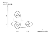
上述の(2)の判断基準において、キャリア・アグリゲーションを選択時の伝送容量(周波数利用品質)およびMIMOを選択時の伝送容量(空間利用品質)のいずれが優位であるかについては、例えば、周波数利用品質-空間利用品質の関係を示す2次元座標上で評価することができる。
図8は、本発明の実施の形態に従う通信システムにおける周波数/空間利用の判断方法を説明するための図である。図8を参照して、縦軸にコンポーネントキャリア数(周波数利用)をとり、横軸にMIMOストリーム数(空間利用)をとる。そして、周波数利用品質(周波数f1,f2)と空間利用品質(ストリームST1,ST2)とについて、基地局装置200と端末装置100との間の送信データに関するチャネル品質などを考慮して、グラフ上のいずれの位置に設定すると、全体としてのスループットを最大化できるかについて検討する。
例えば、パワーアンプPA1,PA2(送信部)を実線で示される楕円内に配置することでスループットを向上できる場合には、キャリア・アグリゲーションが選択される。これに対して、パワーアンプPA1,PA2(送信部)を破線で示される楕円内に配置することでスループットを向上できる場合には、MIMOが選択される。
<8.処理フロー>
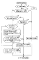
次に、上述したような判断基準に沿って実行される処理手順について、図9を参照して説明する。図9は、本発明の実施の形態に従う通信システムにおいて利用される基地局装置200での処理手順を示すフローチャートである。
次に、上述したような判断基準に沿って実行される処理手順について、図9を参照して説明する。図9は、本発明の実施の形態に従う通信システムにおいて利用される基地局装置200での処理手順を示すフローチャートである。
まず、基地局装置200の中央処理部210は、いずれかの端末装置100との間でデータ通信が要求されているか否かを判断する(ステップS2)。例えば、中央処理部210は、端末装置100に対して送信されるデータ(ダウンリンクデータ)をコアネットワーク装置300から受信すると、データ通信が要求されていると判断する。あるいは、中央処理部210は、端末装置100からのデータ送信(ダウンリンクデータおよびアップリンクデータ)の要求を受けると、データ通信が要求されていると判断する。
データ通信が要求されていないと判断された場合(ステップS2においてNOの場合)には、処理は終了する。
これに対して、データ通信が要求されていると判断された場合(ステップS2においてYESの場合)には、中央処理部210は、基地局装置200と端末装置100との間で送信されるべきデータ量が所定値を超えているか否かを判断する(ステップS4)。この所定値は、通常の通信方式に比較して、高速かつ大容量で通信を行う必要があるか否かを評価するための指標である。なお、LTEおよびLTE-Aでは、リソースブロックをスケジューリングするために、送信を要求するデータ量が端末装置100から基地局装置200へ通知される。そのため、ステップS4においては、基地局装置200から端末装置100へ送信が予定されるデータ量および/または端末装置100から基地局装置200へ送信が予定されているデータ量について評価することができる。
基地局装置200と端末装置100との間で送信されるべきデータ量が所定値を超えていない場合(ステップS4においてNOの場合)には、中央処理部210は、高速かつ大容量で通信を行う必要はないとみなし、通常の通信方式を選択し、(必要があれば)その選択された通信方式を示す指示を出力する(ステップS6)。すなわち、既にいずれかのコンポーネントキャリアにキャンプオンしている場合には、その状態を維持すればよいので、特別な通知は行われない。
そして、通信方式の選択処理は終了し、データの送受信処理が開始される。
一方、基地局装置200と端末装置100との間で送信されるべきデータ量が所定値を超えている場合(ステップS4においてYESの場合)には、中央処理部210は、キャリア・アグリゲーションの実行が可能であるか否かを判断する(ステップS8)。より具体的には、中央処理部210は、コンポーネントキャリアを割当てるための空きが周波数帯に存在するか否かを判断する。すなわち、中央処理部210は、無線リソースの空き状況を評価する。
一方、基地局装置200と端末装置100との間で送信されるべきデータ量が所定値を超えている場合(ステップS4においてYESの場合)には、中央処理部210は、キャリア・アグリゲーションの実行が可能であるか否かを判断する(ステップS8)。より具体的には、中央処理部210は、コンポーネントキャリアを割当てるための空きが周波数帯に存在するか否かを判断する。すなわち、中央処理部210は、無線リソースの空き状況を評価する。
キャリア・アグリゲーションの実行が不可能である場合(ステップS8においてNOの場合)には、中央処理部210は、MIMOの実行が可能であるか否かを判断する(ステップS10)。より具体的には、中央処理部210は、端末装置100および基地局装置200の両方がMIMOをサポートしているか否かを判断する。この判断には、端末装置100から送信される情報などが用いられる。ここで、MIMOの実行が不可能である場合(ステップS10においてNOの場合)には、中央処理部210は、キャリア・アグリゲーションおよびMIMOのいずれについても実行が不可能であると決定する。そして、中央処理部210は、通常の通信方式を選択し、(必要があれば)その選択された通信方式を示す指示を出力する(ステップS6)。そして、通信方式の選択処理は終了し、データの送受信処理が開始される。
これに対して、MIMOの実行が可能である場合(ステップS10においてYESの場合)には、中央処理部210は、通信方式としてMIMOを選択し、MIMOが選択されたことを示す指示を出力する(ステップS12)。そして、通信方式の選択処理は終了し、データの送受信処理が開始される。
一方、キャリア・アグリゲーションの実行が可能である場合(ステップS8においてYESの場合)には、中央処理部210は、MIMOの実行についても可能であるか否かを判断する(ステップS14)。より具体的には、中央処理部210は、端末装置100および基地局装置200の両方がMIMOをサポートしているか否かを判断する。MIMOの実行が不可能である場合(ステップS14においてNOの場合)には、中央処理部210は、通信方式としてキャリア・アグリゲーションを選択し、キャリア・アグリゲーションが選択されたことを示す指示を出力する(ステップS16)。そして、通信方式の選択処理は終了し、データの送受信処理が開始される。
これに対して、MIMOの実行が可能である場合(ステップS14においてYESの場合)には、中央処理部210は、キャリア・アグリゲーションを利用した場合に得られるであろう伝送容量(周波数利用品質)と、MIMOを利用した場合に得られるであろう伝送容量(空間利用品質)とをそれぞれ算出する(ステップS18)。続いて、中央処理部210は、キャリア・アグリゲーションを利用した場合に得られるであろう伝送容量(周波数利用品質)がMIMOを利用した場合に得られるであろう伝送容量(空間利用品質)より大きいか否かを判断する(ステップS20)。
キャリア・アグリゲーションを利用した場合に得られるであろう伝送容量(周波数利用品質)がMIMOを利用した場合に得られるであろう伝送容量(空間利用品質)より大きい場合(ステップS20においてYESの場合)には、中央処理部210は、通信方式としてキャリア・アグリゲーションを選択し、キャリア・アグリゲーションが選択されたことを示す指示を出力する(ステップS16)。そして、通信方式の選択処理は終了し、データの送受信処理が開始される。
一方、MIMOを利用した場合に得られるであろう伝送容量(空間利用品質)がキャリア・アグリゲーションを利用した場合に得られるであろう伝送容量(周波数利用品質)より大きい場合(ステップS18においてNOの場合)には、中央処理部210は、通信方式としてMIMOを選択し、MIMOが選択されたことを示す指示を出力する(ステップS12)。そして、通信方式の選択処理は終了し、データの送受信処理が開始される。
次に、上述のフローチャートに示す通信方式の判断処理を含むシステム全体の処理手順について説明する。
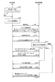
図10は、本発明の実施の形態に従う通信システムにおいて利用される基地局装置200での処理手順を示すシーケンス図である。図10を参照して、初期状態として、端末装置100が待ち受け状態であるとする(シーケンスSQ2)。この初期状態において、端末装置100は、例えば、バンドIに設定されているダウンリンクコンポーネントキャリアDLCCIにキャンプオンしているものとする。
ここで、ユーザが端末装置100を操作することによって、端末装置100へのダウンロードといったパケット通信要求が端末装置100で発生したとする(シーケンスSQ4)。端末装置100は、基地局装置200と接続するためにキャンプオンしているダウンリンクコンポーネントキャリアDLCCIに対応するアップリンクコンポーネントキャリアULCCIを利用して、基地局装置200と通信を確立する(シーケンスSQ6)。なお、対応するアップリンクコンポーネントキャリアULCCIは、基地局装置200から端末装置100への報知情報によって通知される。続いて、端末装置100は、当該アップリンクコンポーネントキャリアULCCIを利用して、特定のアクセス先からのダウンロードの要求に加えて、発信元の端末装置100に関する情報(例えば、キャリア・アグリゲーション/MIMOへの対応可否、アンテナの数、パワーアンプ(送信回路)の数など)を含むパケット通信要求を基地局装置200へ送信する(シーケンスSQ8)。
基地局装置200は、端末装置100からのパケット通信要求を受信すると、それぞれのダウンリンクコンポーネントキャリアDLCCについての品質測定要求を端末装置100へ送信する(シーケンスSQ10)。典型的には、この品質測定要求は、報知チャネル、下り共通チャネル、下り個別チャネルのいずれか用いて端末装置100へ通知される。但し、その他の通知手段(チャネル)を用いて通知されてもよい。
端末装置100は、基地局装置200からの品質測定要求を受信すると、測定要求の対象となっているダウンリンクコンポーネントキャリアDLCCについての品質を測定し、当該測定によって得られた品質レベルを含むチャネル品質報告(Channel Quality Indication:CQI)を基地局装置200へ通知する(シーケンスSQ12)。
基地局装置200は、(1)基地局装置200と端末装置100との間で送信されるべきデータ量、(2)無線リソースの空き状況、(3)端末装置100からのチャネル品質報告などに基づいて、上述の図9に示すような通信方式の判断処理を実行する(シーケンスSQ14)。すなわち、基地局装置200は、通常の通信方式、キャリア・アグリゲーション、MIMOのいずれで通信を行うのかを決定する。
より具体的には、基地局装置200は、通信方式としてキャリア・アグリゲーションを選択した場合(シーケンスSQ14において「CA」)には、キャリア・アグリゲーションの実行に必要な情報、例えば、DLCCセットおよびULCCセットを決定する。そして、基地局装置200は、これらの情報を含めて、キャリア・アグリゲーションが選択されたことを示す指示を端末装置100へ通知する(シーケンスSQ16)。端末装置100は、基地局装置200から通知されたDLCCセットおよびULCCセットに従って、送信部132,134および受信部136,138の設定を変更する。また、基地局装置200は、決定したDLCCセットおよびULCCセットに従って、送信部232,234および受信部236,238の設定を変更する。そして、基地局装置200と端末装置100とは、キャリア・アグリゲーションを利用して通信を開始する(シーケンスSQ18)。
なお、基地局装置200から端末装置100へ通知される情報としては、決定したDLCCセットおよびULCCセットに加えて、その他、キャリア・アグリゲーションの制御に必要な他のDLCCセットおよび/またはULCCセットなどを含めることもできる。
一方、基地局装置200は、通信方式としてMIMOを選択した場合(シーケンスSQ14において「MIMO」)には、MIMOの実行に必要な情報、例えば、ストリーム数などを決定する。そして、基地局装置200は、これらの情報を含めて、MIMOが選択されたことを示す指示を端末装置100へ通知する(シーケンスSQ20)。端末装置100は、基地局装置200から通知された情報に従って、送信部132,134および受信部136,138の設定を変更する。また、基地局装置200は、MIMOに従って、送信部232,234および受信部236,238の設定を変更する。そして、基地局装置200と端末装置100とは、MIMOを利用して通信を開始する(シーケンスSQ22)。
また、基地局装置200は、通常の通信方式を選択した場合(シーケンスSQ14において「通常」)には、基本的には、特別な通知をしない。そのため、基地局装置200と端末装置100とは、現在設定されているコンポーネントキャリア(この例では、DLCCI)を利用して通信を開始する(シーケンスSQ24)。
なお、図9および図10においては、パケット通信要求などのイベントが発生した場合に通信方式の選択処理を実行する例について示すが、基地局装置200と端末装置100との間で通信中においても、通信方式の選択処理を実行するとともに、必要に応じて通信方式を切換えることができる。すなわち、基地局装置200と端末装置100との間で、キャリア・アグリゲーションまたはMIMOを利用してデータ通信が行われている最中にも、端末装置100からのチャネル品質報告などに基づいて、通信品質を随時監視する。そして、図9に示すような通信方式の判断手順に沿って、最適なスループットを実現できるような通信方式を選択する。そして、通信方式を切換える必要があると判断されると、上述と同様の処理で通信方式を切換える。
<9.変形例>
上述の実施の形態においては、主として、基地局装置200に通信方式を選択するロジックが存在する例を示したが、端末装置100にこのようなロジックが存在してもよい。すなわち、端末装置100が主導して適切な通信方式を選択することで、最適なスループットを実現することができる。
上述の実施の形態においては、主として、基地局装置200に通信方式を選択するロジックが存在する例を示したが、端末装置100にこのようなロジックが存在してもよい。すなわち、端末装置100が主導して適切な通信方式を選択することで、最適なスループットを実現することができる。
<10.まとめ>
複数の通信方式(典型的には、キャリア・アグリゲーションおよびMIMO)に対応する端末装置を実現しようとした場合、各通信方式に対応する専用回路を端末装置に実装すると、回路規模が大きくなってしまい、また、消費電力が不要に増加するという事態が生じえるが、本実施の形態に従えば、回路規模の増大を抑制するとともに、消費電力の不要な増加についても抑制できる。
複数の通信方式(典型的には、キャリア・アグリゲーションおよびMIMO)に対応する端末装置を実現しようとした場合、各通信方式に対応する専用回路を端末装置に実装すると、回路規模が大きくなってしまい、また、消費電力が不要に増加するという事態が生じえるが、本実施の形態に従えば、回路規模の増大を抑制するとともに、消費電力の不要な増加についても抑制できる。
例えば、各通信方式において2系統の入力を有する回路を実装する場合には、キャリア・アグリゲーションについては2つのパワーアンプと、MIMOについては2×2=計4つのパワーアンプとが必要になる。
これに対して、本実施の形態に従う無線通信システムにおいては、共通の送信回路および受信回路をいずれの通信方式においても利用するので、回路の利用効率を高めることができる。このように、本実施の形態に従う無線通信システムにおいては、回路を共有化することにより、回路規模の増大および消費電力の増大のいずれをも回避するとともに、通信環境や送信が要求されたデータ量などに応じて通信方式を選択することで、最適なスループットを実現することができる。
また、本実施の形態に従う無線通信システムにおいては、より高速かつ大容量のデータ通信を実現する必要があると判断された場合に、キャリア・アグリゲーションまたはMIMOのいずれかを選択して、基地局装置と端末装置との間でデータ通信を行う。そのため、周波数帯域を不要に占有することを回避して、要求に応じたスループットを実現できる。
さらに、本実施の形態に従う無線通信システムにおいては、使用する通信方式を選択するロジックを基地局装置側に配置してもよいし、端末装置側に配置してもよい。これにより、システムの運用形態に応じて適切な構成を採用することができる。
基地局装置に通信方式を選択するロジックを配置した場合には、端末装置の回路構成をより簡素化できるので、端末装置のコストを低減できる。
一方、端末装置に通信方式を選択するロジックを配置した場合には、現在運用されている従来の無線通信システムにおいて、基地装置の一部を改良することで、本実施の形態に従う無線通信システムを実現することができる。また、この場合には、基地局装置のコストを低減できる。
今回開示された実施の形態はすべての点で例示であって制限的なものではないと考えられるべきである。本発明の範囲は、上記した説明ではなく、請求の範囲によって示され、請求の範囲と均等の意味および範囲内でのすべての変更が含まれることが意図される。
100 端末装置、110,210 中央処理部、120 表示部、122 マイク、124 スピーカ、126 入力部、130,230 信号処理部、132,134,232,234 送信部、136,138,236,238 受信部、142,144,242,244 送信アンテナ、146,148,246,248 受信アンテナ、150 筐体、200 基地局装置、212 通信方式選択ロジック、222 上位ネットワークインターフェイス、224 制御インターフェイス、300 コアネットワーク装置、400 コアネットワーク。
Claims (13)
- 無線信号を生成するための送信部を複数含む基地局装置と、
無線信号を生成するための送信部を複数含む端末装置と、
前記基地局装置と前記端末装置との間の通信環境および要求されたデータ量を含む、通信情報に基づいて、前記基地局装置の複数の送信部および前記端末装置の複数の送信部に対する周波数の割当て形態が異なる複数の通信方式の中から使用すべき通信方式を決定する通信方式決定手段とを備える、無線通信システム。 - 前記通信方式決定手段は、
前記基地局装置の送信部のうち第1の送信部が第1の周波数帯域の無線信号を送信するとともに、前記基地局装置の送信部のうち第2の送信部が第2の周波数帯域の無線信号を送信する第1の通信方式と、
同一の周波数帯域において、前記第1および第2の送信部がそれぞれ第1および第2の無線信号を送信する第2の通信方式との間で、通信方式を選択する、請求項1に記載の無線通信システム。 - 前記通信方式決定手段は、
前記端末装置の送信部のうち第1の送信部が第1の周波数帯域の無線信号を送信するとともに、前記端末装置の送信部のうち第2の送信部が第2の周波数帯域の無線信号を送信する第1の通信方式と、
同一の周波数帯域において、前記第1および第2の送信部がそれぞれ第1および第2の無線信号を送信する第2の通信方式との間で、通信方式を選択する、請求項1に記載の無線通信システム。 - 前記通信方式決定手段は、前記基地局装置の送信部および前記端末装置の送信部に対して、キャリア・アグリゲーション方式およびMIMO(Multiple-Input Multiple-Output)方式のいずれかを設定する、請求項1に記載の無線通信システム。
- 前記通信方式決定手段は、さらに、前記端末装置のチャネル品質報告に基づいて、通信方式を決定する、請求項1~4のいずれか1項に記載の無線通信システム。
- 前記通信方式決定手段は、前記端末装置の接続要求に応答して、通信方式を決定する、請求項1~4のいずれか1項に記載の無線通信システム。
- 前記接続要求は、前記端末装置がサポートしている通信方式の情報、および、送信を要求するデータ量の少なくとも一方を含む、請求項6に記載の無線通信システム。
- 前記通信方式決定手段は、選択した通信方式を、報知チャネル、下り共通チャネル、下り個別チャネルのいずれか1つを用いて、前記基地局装置から前記端末装置へ通知する、請求項1に記載の無線通信システム。
- 無線信号を生成するための送信部を複数含む端末装置と通信可能な基地局装置であって、
前記無線信号を受信するための複数の受信部と、
前記基地局装置と前記端末装置との間の通信環境および要求されたデータ量を含む、通信情報に基づいて、前記複数の送信部および前記複数の受信部に対する周波数の割当て形態が異なる複数の通信方式の中から使用すべき通信方式を決定する通信方式決定手段と、
決定された通信方式に従って、前記複数の送信部の動作を設定するための情報を前記端末装置へ送信するとともに、前記複数の受信部の動作を設定する設定手段とを備える、基地局装置。 - 無線信号を受信するための受信部を複数含む端末装置と通信可能な基地局装置であって、
前記無線信号を生成するための複数の送信部と、
前記基地局装置と前記端末装置との間の通信環境および要求されたデータ量を含む、通信情報に基づいて、前記複数の送信部および前記複数の受信部に対する周波数の割当て形態が異なる複数の通信方式の中から使用すべき通信方式を決定する通信方式決定手段と、
決定された通信方式に従って、前記複数の受信部の動作を設定するための情報を前記端末装置へ送信するとともに、前記複数の送信部の動作を設定する設定手段とを備える、基地局装置。 - 無線信号を受信するための受信部を複数含む基地局装置と通信可能な端末装置であって、
前記無線信号を生成するための複数の送信部と、
前記基地局装置と前記端末装置との間の通信環境および要求されたデータ量を含む、通信情報に基づいて、前記複数の送信部および前記複数の受信部に対する周波数の割当て形態が異なる複数の通信方式の中から使用すべき通信方式を決定する通信方式決定手段と、
決定された通信方式に従って、前記複数の受信部の動作を設定するための情報を前記基地局装置へ送信するとともに、前記複数の送信部の動作を設定する設定手段とを備える、端末装置。 - 無線信号を生成するための送信部を複数含む基地局装置と通信可能な端末装置であって、
前記無線信号を受信するための複数の受信部と、
前記基地局装置と前記端末装置との間の通信環境および要求されたデータ量を含む、通信情報に基づいて、前記複数の送信部および前記複数の受信部に対する周波数の割当て形態が異なる複数の通信方式の中から使用すべき通信方式を決定する通信方式決定手段と、
決定された通信方式に従って、前記複数の送信部の動作を設定するための情報を前記基地局装置へ送信するとともに、前記複数の受信部の動作を設定する設定手段とを備える、端末装置。 - 基地局装置と端末装置との間での無線通信方法であって、前記基地局装置および前記端末装置の各々は、無線信号を生成するための送信部を複数含み、
前記基地局装置と前記端末装置との間の通信環境および要求されたデータ量を含む、通信情報を取得するステップと、
前記基地局装置の複数の送信部および前記端末装置の複数の送信部に対する周波数の割当て形態が異なる複数の通信方式の中から使用すべき通信方式を決定するステップと、
前記決定された通信方式に従って、前記基地局装置の複数の送信部の動作を設定するステップと、
前記決定された通信方式に従って、前記端末装置の複数の送信部の動作を設定するステップとを備える、無線通信方法。
Applications Claiming Priority (2)
| Application Number | Priority Date | Filing Date | Title |
|---|---|---|---|
| JP2011001158 | 2011-01-06 | ||
| JP2011-001158 | 2011-01-06 |
Publications (1)
| Publication Number | Publication Date |
|---|---|
| WO2012093685A1 true WO2012093685A1 (ja) | 2012-07-12 |
Family
ID=46457536
Family Applications (1)
| Application Number | Title | Priority Date | Filing Date |
|---|---|---|---|
| PCT/JP2012/050081 Ceased WO2012093685A1 (ja) | 2011-01-06 | 2012-01-05 | 無線通信システム、基地局装置、端末装置、および、無線通信方法 |
Country Status (1)
| Country | Link |
|---|---|
| WO (1) | WO2012093685A1 (ja) |
Cited By (2)
| Publication number | Priority date | Publication date | Assignee | Title |
|---|---|---|---|---|
| JP2014132742A (ja) * | 2012-12-07 | 2014-07-17 | Nec Corp | 送信装置及び無線信号送信方法 |
| CN113271113A (zh) * | 2021-06-03 | 2021-08-17 | Oppo广东移动通信有限公司 | 射频系统、射频组件和通信设备 |
Citations (1)
| Publication number | Priority date | Publication date | Assignee | Title |
|---|---|---|---|---|
| JP2011071706A (ja) * | 2009-09-25 | 2011-04-07 | Sony Corp | 通信システム、基地局、および通信装置 |
-
2012
- 2012-01-05 WO PCT/JP2012/050081 patent/WO2012093685A1/ja not_active Ceased
Patent Citations (1)
| Publication number | Priority date | Publication date | Assignee | Title |
|---|---|---|---|---|
| JP2011071706A (ja) * | 2009-09-25 | 2011-04-07 | Sony Corp | 通信システム、基地局、および通信装置 |
Non-Patent Citations (2)
| Title |
|---|
| "Discussion on RAN1 LS on Rel-10 UE Category", 3GPP TSG RAN WG2 #71BIS, R2-105455, 11 October 2010 (2010-10-11) * |
| "Flexible CA/MIMO configuration and related CA/MIMO capabilities information", 3GPP TSG RAN WG4 MEETING AD HOC 2010#3, R4-102612, 28 June 2010 (2010-06-28) * |
Cited By (4)
| Publication number | Priority date | Publication date | Assignee | Title |
|---|---|---|---|---|
| JP2014132742A (ja) * | 2012-12-07 | 2014-07-17 | Nec Corp | 送信装置及び無線信号送信方法 |
| US9787389B2 (en) | 2012-12-07 | 2017-10-10 | Nec Corporation | Transmission device and radio signal transmission method |
| CN113271113A (zh) * | 2021-06-03 | 2021-08-17 | Oppo广东移动通信有限公司 | 射频系统、射频组件和通信设备 |
| CN113271113B (zh) * | 2021-06-03 | 2022-08-09 | Oppo广东移动通信有限公司 | 射频系统、射频组件和通信设备 |
Similar Documents
| Publication | Publication Date | Title |
|---|---|---|
| KR102135335B1 (ko) | 무선 통신 시스템에서 데이터를 송수신하는 방법 및 이를 위한 장치 | |
| CN115336189B (zh) | 双连接中的天线管理 | |
| CN105229942B (zh) | 用于资源分配和设备对设备发现跳的用户设备和方法 | |
| RU2714104C2 (ru) | Системы и способы одновременного использования диапазона частот в активно используемом диапазоне частот | |
| WO2019096206A1 (zh) | 无线通信系统中的装置和方法、计算机可读存储介质 | |
| KR20200119260A (ko) | 적어도 4 개의 안테나들을 갖는 스케줄링되는 엔티티에서의 사운딩 레퍼런스 신호 안테나 스위칭 | |
| US20110205976A1 (en) | UE Specific Signaling Carrier Indicator For Carrier Aggregation | |
| CN112004266B (zh) | 跨多个载波的动态处理资源分配 | |
| US20200374050A1 (en) | Inter-Radio Access Technology Carrier Aggregation | |
| US20130279446A1 (en) | Carrier Aggregation Scheduling Apparatus, Carrier Aggregation Scheduling Method, and Base Station | |
| WO2019108267A1 (en) | Lte resource allocation | |
| CN113615234B (zh) | 终端设备、基站设备、通信方法和基站设备控制方法 | |
| WO2011043392A1 (ja) | 基地局装置及びユーザ装置 | |
| WO2020196279A1 (ja) | 通信装置、基地局装置、通信方法、及び基地局装置の制御方法 | |
| TW201906337A (zh) | 通訊裝置、通訊控制方法及電腦程式 | |
| WO2011043394A1 (ja) | ユーザ装置、基地局装置及び移動通信方法 | |
| WO2020031704A1 (ja) | 通信装置、通信制御方法及び記録媒体 | |
| KR20130122201A (ko) | 멀티 포인트 전송 환경에서의 무선 데이터 송수신 방법 | |
| KR20190011634A (ko) | 무선 통신 시스템에서 대역폭을 결정하기 위한 장치 및 방법 | |
| US11503595B2 (en) | Mobile communication method | |
| US12581498B2 (en) | Downlink quality improvement method and apparatus | |
| JP7472901B2 (ja) | 通信装置、基地局装置、通信方法、及び基地局装置の制御方法 | |
| US20240397391A1 (en) | Communication method, user equipment, and base station | |
| WO2012093685A1 (ja) | 無線通信システム、基地局装置、端末装置、および、無線通信方法 | |
| JP5846518B2 (ja) | セル能力情報インタラクションのための方法、デバイス及びシステム |
Legal Events
| Date | Code | Title | Description |
|---|---|---|---|
| 121 | Ep: the epo has been informed by wipo that ep was designated in this application |
Ref document number: 12732431 Country of ref document: EP Kind code of ref document: A1 |
|
| NENP | Non-entry into the national phase |
Ref country code: DE |
|
| 122 | Ep: pct application non-entry in european phase |
Ref document number: 12732431 Country of ref document: EP Kind code of ref document: A1 |
|
| NENP | Non-entry into the national phase |
Ref country code: JP |