WO2012090917A1 - Tire - Google Patents
Tire Download PDFInfo
- Publication number
- WO2012090917A1 WO2012090917A1 PCT/JP2011/080030 JP2011080030W WO2012090917A1 WO 2012090917 A1 WO2012090917 A1 WO 2012090917A1 JP 2011080030 W JP2011080030 W JP 2011080030W WO 2012090917 A1 WO2012090917 A1 WO 2012090917A1
- Authority
- WO
- WIPO (PCT)
- Prior art keywords
- groove
- tire
- protrusion
- side wall
- tread
- Prior art date
Links
Images


Classifications
-
- B—PERFORMING OPERATIONS; TRANSPORTING
- B60—VEHICLES IN GENERAL
- B60C—VEHICLE TYRES; TYRE INFLATION; TYRE CHANGING; CONNECTING VALVES TO INFLATABLE ELASTIC BODIES IN GENERAL; DEVICES OR ARRANGEMENTS RELATED TO TYRES
- B60C11/00—Tyre tread bands; Tread patterns; Anti-skid inserts
-
- B—PERFORMING OPERATIONS; TRANSPORTING
- B60—VEHICLES IN GENERAL
- B60C—VEHICLE TYRES; TYRE INFLATION; TYRE CHANGING; CONNECTING VALVES TO INFLATABLE ELASTIC BODIES IN GENERAL; DEVICES OR ARRANGEMENTS RELATED TO TYRES
- B60C11/00—Tyre tread bands; Tread patterns; Anti-skid inserts
- B60C11/03—Tread patterns
- B60C11/04—Tread patterns in which the raised area of the pattern consists only of continuous circumferential ribs, e.g. zig-zag
- B60C11/042—Tread patterns in which the raised area of the pattern consists only of continuous circumferential ribs, e.g. zig-zag further characterised by the groove cross-section
-
- B—PERFORMING OPERATIONS; TRANSPORTING
- B60—VEHICLES IN GENERAL
- B60C—VEHICLE TYRES; TYRE INFLATION; TYRE CHANGING; CONNECTING VALVES TO INFLATABLE ELASTIC BODIES IN GENERAL; DEVICES OR ARRANGEMENTS RELATED TO TYRES
- B60C11/00—Tyre tread bands; Tread patterns; Anti-skid inserts
- B60C11/03—Tread patterns
- B60C11/13—Tread patterns characterised by the groove cross-section, e.g. for buttressing or preventing stone-trapping
- B60C11/1307—Tread patterns characterised by the groove cross-section, e.g. for buttressing or preventing stone-trapping with special features of the groove walls
- B60C2011/1338—Tread patterns characterised by the groove cross-section, e.g. for buttressing or preventing stone-trapping with special features of the groove walls comprising protrusions
-
- B—PERFORMING OPERATIONS; TRANSPORTING
- B60—VEHICLES IN GENERAL
- B60C—VEHICLE TYRES; TYRE INFLATION; TYRE CHANGING; CONNECTING VALVES TO INFLATABLE ELASTIC BODIES IN GENERAL; DEVICES OR ARRANGEMENTS RELATED TO TYRES
- B60C11/00—Tyre tread bands; Tread patterns; Anti-skid inserts
- B60C11/03—Tread patterns
- B60C11/13—Tread patterns characterised by the groove cross-section, e.g. for buttressing or preventing stone-trapping
- B60C11/1353—Tread patterns characterised by the groove cross-section, e.g. for buttressing or preventing stone-trapping with special features of the groove bottom
- B60C2011/1361—Tread patterns characterised by the groove cross-section, e.g. for buttressing or preventing stone-trapping with special features of the groove bottom with protrusions extending from the groove bottom
-
- B—PERFORMING OPERATIONS; TRANSPORTING
- B60—VEHICLES IN GENERAL
- B60C—VEHICLE TYRES; TYRE INFLATION; TYRE CHANGING; CONNECTING VALVES TO INFLATABLE ELASTIC BODIES IN GENERAL; DEVICES OR ARRANGEMENTS RELATED TO TYRES
- B60C2200/00—Tyres specially adapted for particular applications
- B60C2200/06—Tyres specially adapted for particular applications for heavy duty vehicles
Definitions
- the present invention relates to a tire that suppresses a temperature rise of the tire accompanying traveling.
- a pneumatic tire (hereinafter referred to as a tire) that is mounted on a vehicle
- various methods are used in order to suppress an increase in the temperature of the tire as the vehicle runs.
- the temperature rise is significant in heavy-duty tires mounted on trucks, buses, construction vehicles, and the like.
- a tire in which a large number of fin-like protrusions are provided on a sidewall portion of the tire (for example, Patent Document 1).
- Patent Document 1 a tire in which a large number of fin-like protrusions are provided on a sidewall portion of the tire.
- FIG. 1 is a schematic perspective view of a pneumatic tire 10 according to an embodiment of the present invention.
- FIG. 2 is a cross-sectional view of the pneumatic tire 10 according to the embodiment of the present invention along the tread width direction and the tire radial direction.
- FIG. 3 is a partially broken perspective view of the groove 30 according to the embodiment of the present invention.
- FIG. 4 is a diagram illustrating a shape of the groove portion 30 according to the embodiment of the present invention in a tread surface view (a viewpoint above the tread portion 20).
- FIG. 5 is a diagram showing the shape of the groove 30 from the F5 direction in FIG.
- FIG. 6 is a cross-sectional view of the groove 30 (projection 100) taken along line F6-F6 of FIG.
- FIG. 7 is a graph showing the relationship between the angle ⁇ and the heat transfer coefficient (index display) in the groove 30.
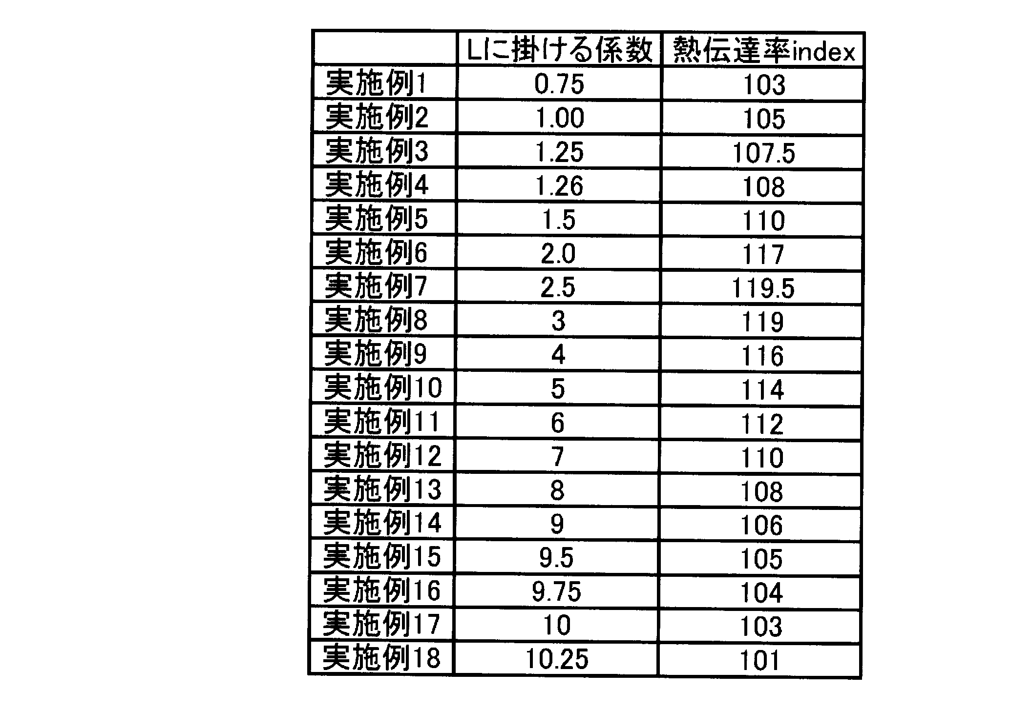
- FIG. 8 is a graph showing the relationship between the coefficient applied to the length L of the protrusion 100 and the heat transfer coefficient in the groove 30.
- FIG. 9 is a graph showing the relationship between the coefficient applied to the groove depth D of the protrusion 100 and the heat transfer coefficient in the groove 30.
- FIG. 10 is a diagram showing a cross-sectional shape of the protrusion 100 according to a modification of the present invention.
- FIG. 1 is a schematic perspective view of a pneumatic tire 10 according to this embodiment.
- the pneumatic tire 10 is a pneumatic radial tire mounted on a construction vehicle (ORR) such as a truck or bus (TBR) or a dump truck.
- the pneumatic tire 10 may be filled with an inert gas such as nitrogen gas.
- the pneumatic tire 10 has a tread portion 20 that can come into contact with the road surface.
- a groove portion 30 is formed in the tread portion 20.
- the groove part 30 is a linear groove extending in the tire circumferential direction.
- a plurality of protrusions 100 are provided inside the groove 30.
- the pneumatic tire 10 is attached to the vehicle so as to rotate in the rotation direction R when the vehicle moves forward.
- the direction of rotation of the pneumatic tire 10 in the vehicle device is not particularly specified.
- FIG. 2 is a cross-sectional view of the pneumatic tire 10 along the tread width direction and the tire radial direction.
- the pneumatic tire 10 has a belt layer 40 composed of a plurality of belts.
- the pneumatic tire 10 has a rubber gauge (rubber thickness) of the tread portion 20 larger than that of a pneumatic tire mounted on a passenger car or the like.
- the pneumatic tire 10 satisfies DC / OD ⁇ 0.015 when the tire outer diameter is OD and the rubber gauge of the tread portion 20 at the position of the tire equator line CL is DC.
- the tire outer diameter OD (unit: mm) is the diameter of the pneumatic tire 10 at a portion (generally, the tread portion 20 near the tire equator line CL) where the outer diameter of the pneumatic tire 10 is maximum.
- the rubber gauge DC (unit: mm) is the rubber thickness of the tread portion 20 at the position of the tire equator line CL.
- the rubber gauge DC does not include the thickness of the belt layer 40. As shown in FIG. 2, when the groove portion 30 is formed at a position including the tire equator line CL, the rubber thickness of the tread portion 20 at a position adjacent to the groove portion 30 is used.
- FIG. 3 is a partially broken perspective view of the groove 30.
- FIG. 4 shows the shape of the groove part 30 in a tread surface view (viewpoint above the tread part 20).
- FIG. 5 shows the shape of the groove 30 from the F5 direction in FIG.
- FIG. 6 is a cross-sectional view of the groove 30 (projection 100) taken along line F6-F6 of FIG.
- a plurality of protrusions 100 are provided on the groove bottom 32 of the groove 30.
- the protrusions 100 are provided at predetermined intervals P in the groove 30. Further, the protrusion 100 extends from one side wall 31 forming the protrusion 100 toward the other side wall 33. In the present embodiment, the protrusion 100 is continuous from one side wall 31 to the other side wall 33. That is, the protrusion 100 is provided over the entire groove width W of the groove 30. In the present embodiment, the side wall 31 and the side wall 33 extend substantially parallel to the tire circumferential direction, and the side wall 31 and the side wall 33 are formed to face each other.
- the protrusion 100 is provided so as to stand from the groove bottom 32 of the groove 30 to the outside in the tire radial direction.
- the protrusion 100 is a flat rubber that rises from the groove bottom 32, and is provided to be inclined with respect to the tire circumferential direction.
- the angle ⁇ formed by the groove center line WL and the protrusion 100 is not less than 10 degrees and not more than 60 degrees.
- the angle ⁇ is an angle formed by the arrangement direction of the protrusion 100 and the groove center line WL passing through the center in the width direction of the groove 30 in the tread surface view of the pneumatic tire 10, and the rotation of the pneumatic tire 10 An angle formed on the opposite side of the direction. That is, the angle ⁇ is an angle formed on the traveling direction side of the traveling wind WD generated when the pneumatic tire 10 rolls in the rotation direction R.
- the protrusion 100 provided in the groove 30 is 0.75L. ⁇ P ⁇ 10L is satisfied.
- the length L is the length from one end to the other end of the protrusion 100 in the extending direction of the groove 30 (in the present embodiment, the tire circumferential direction).
- the interval P is a distance between the centers of the protrusions 100 at which the protrusions 100 and the groove center line WL intersect.
- the length L can also be expressed as W / tan ⁇ + TW / sin ⁇ .
- the protrusion width TW is the width of the protrusion 100 in the short direction of the protrusion 100, that is, in the direction orthogonal to the extending direction of the protrusion 100, as shown in FIG.
- the protrusion 100 Satisfies the relationship 0.03D ⁇ H ⁇ 0.4D.
- the groove width of the groove portion 30 is W
- the groove bottom 32 is flat at a width of at least 0.2 W. That is, the central portion including the groove center line WL in the groove width W of the groove bottom 32 has no unevenness and the surface of the groove bottom 32 is smooth.
- FIG. 7 shows the relationship between the angle ⁇ and the heat transfer coefficient (index display) in the groove 30.
- FIG. 8 shows the relationship between the coefficient applied to the length L of the protrusion 100 and the heat transfer coefficient in the groove 30.
- FIG. 9 shows the relationship between the coefficient applied to the groove depth D of the protrusion 100 and the heat transfer coefficient in the groove 30.
- Table 1 shows the relationship between the coefficient applied to the length L of the protrusion 100 and the heat transfer coefficient in the groove 30.
- the angle ⁇ is preferably 10 degrees to 60 degrees.
- the angle ⁇ is less than 10 degrees, the flow of the traveling wind WD becomes extremely weak due to the acute angle portion formed by the protrusion 100 and the side wall 31 (or the side wall 33), and efficient heat dissipation from the tread portion 20 cannot be achieved. . Further, such a protrusion 100 is difficult to manufacture.
- the angle ⁇ exceeds 60 degrees, the effect of changing the traveling wind WD into a spiral flow becomes weak. For this reason, the amount of air passing through the groove bottom 32 is reduced, and efficient heat dissipation from the tread portion 20 cannot be achieved.
- the coefficient multiplied by the length L is preferably 0.75 to 10.00.
- the coefficient is less than 0.75, the number of protrusions 100 provided in the groove 30 is too large. For this reason, the speed of the traveling wind WD is greatly reduced, and efficient heat dissipation from the tread portion 20 cannot be achieved.
- the coefficient exceeds 10.00, the effect of changing the traveling wind WD into a spiral flow becomes weak. For this reason, the air volume passing through the groove bottom 32 is reduced, and efficient heat radiation from the tread portion 20 cannot be achieved.
- the lower limit value is more important than the upper limit value.
- the coefficient multiplied by the length L is preferably larger than 1.25. That is, it is preferable to satisfy the relationship of 1.25L ⁇ P.
- the coefficient multiplied by the length L is more preferably 1.5 or more, and further preferably 2.0 or more.
- the coefficient multiplied by the groove depth D exceeds 0.03 and is 0.40 or less.
- the coefficient is 0.03 or less, the height of the protrusion 100 in the groove 30 is too low. For this reason, the effect of changing the traveling wind WD into a spiral flow becomes weak, and efficient heat dissipation from the tread portion 20 cannot be achieved.
- the coefficient exceeds 0.400, the traveling wind WD can be changed to a spiral flow, but the traveling wind WD does not easily reach the groove bottom 32, and efficient heat dissipation from the tread portion 20 can be achieved. Absent.
- the groove bottom 32 of the groove portion 30 is provided with the plurality of protrusion portions 100, and the protrusion portion 100 extends from one side wall 31 that forms the groove portion 30 to the other side wall 33. It continues until.
- the protrusion 100 is provided so as to be inclined so as to have an angle ⁇ with respect to the groove center line WL.
- the traveling wind WD gets over such a protrusion 100, the traveling wind WD changes to a spiral (swirl) flow, and the passing speed of the traveling wind WD increases.
- the air volume of the traveling wind WD passing through the groove bottom 32 is increased, and heat dissipation from the tread portion 20 is promoted. That is, according to the pneumatic tire 10, an increase in the temperature of the tread portion 20 as the vehicle travels can be effectively suppressed.
- the temperature rise of the tread portion 20 can be further effectively improved. Can be suppressed.
- the groove bottom 32 is flat at least in a width of 0.2 W, the flow of the traveling wind WD passing through the groove bottom 32 is not hindered, and the temperature rise of the tread portion 20 is more effectively performed. Can be suppressed.
- the groove 30 extends in parallel to the tire circumferential direction, but the groove 30 does not necessarily have to be parallel to the tire circumferential direction.
- the groove portion 30 may not be parallel to the tire circumferential direction as long as the angle formed with the tire equator line CL is 45 degrees or less.
- the groove portion 30 does not necessarily have to be linear, and may be, for example, a shape curved outward in the tread width direction or a zigzag shape.
- the groove part 30 is zigzag-shaped, it is preferable that it is a shape where the speed of the driving
- the shape of the protrusion 100 does not necessarily have to be a flat plate shape.
- the shape of the protrusion 100 is a waveform in a tread surface view, the vicinity of the groove center line WL is thick, and becomes thinner toward the side wall 31 and the side wall 33 ( Alternatively, the shape may be reversed.
- FIGS. 10A to 10G show modifications of the cross-sectional shape of the protrusion 100.
- FIG. As shown in FIGS. 10A to 10G, the upper end of the cross-sectional shape (similar to FIG. 6) of the protrusion 100 may not be flat.
- angle ⁇ , the groove depth D, and the groove width W may not necessarily satisfy the conditions defined in the above-described embodiment.
Abstract
Description
図1は、本実施形態に係る空気入りタイヤ10の概略斜視図である。空気入りタイヤ10は、トラックまたはバス(TBR)、或いはダンプトラックなどの建設用車両(ORR)に装着される空気入りのラジアルタイヤである。なお、空気入りタイヤ10には、窒素ガスなどの不活性ガスを充填してもよい。 (1) Schematic Configuration of Tire FIG. 1 is a schematic perspective view of a
図3は、溝部30の一部破断斜視図である。図4は、溝部30のトレッド面視(トレッド部20の上方の視点)における形状を示す。図5は、図4のF5方向からの溝部30の形状を示す。図6は、図4のF6-F6線に沿った溝部30(突起部100)の断面図である。 (2) Shape of Groove 30 FIG. 3 is a partially broken perspective view of the
次に、図7~図9及び表1を参照して、上述した空気入りタイヤ10の作用及び効果について説明する。図7は、角度θと、溝部30における熱伝達率(指数表示)との関係を示す。図8は、突起部100の長さLに掛ける係数と、溝部30における熱伝達率との関係を示す。図9は、突起部100の溝深さDに掛ける係数と、溝部30における熱伝達率との関係を示す。表1は、突起部100の長さLに掛ける係数と、溝部30における熱伝達率との関係を示す。 (3) Action / Effect Next, the action and effect of the
上述したように、本発明の実施形態を通じて本発明の内容を開示したが、この開示の一部をなす論述及び図面は、本発明を限定するものであると理解すべきではない。この開示から当業者には様々な代替実施の形態、実施例及び運用技術が明らかとなる。 (4) Other Embodiments As described above, the contents of the present invention have been disclosed through the embodiments of the present invention. However, it is understood that the descriptions and drawings constituting a part of this disclosure limit the present invention. Should not. From this disclosure, various alternative embodiments, examples, and operational techniques will be apparent to those skilled in the art.
Claims (8)
- トレッド部にタイヤ周方向に延びる溝部が形成されたタイヤであって、
前記溝部の溝底には、複数の突起部が設けられ、
前記突起部は、前記溝部を形成する一方の側壁から、前記一方の側壁と対向する他方の側壁に向けて延在し、
前記突起部は、前記溝部において所定間隔毎に設けられ、
前記タイヤのトレッド面視において、前記突起部の前記溝中心線に沿った長さをLとし、前記所定間隔をPとした場合、0.75L≦P≦10Lの関係を満たすタイヤ。 A tire in which a groove extending in the tire circumferential direction is formed in the tread portion,
The groove bottom of the groove is provided with a plurality of protrusions,
The protrusion extends from one side wall forming the groove to the other side wall facing the one side wall,
The protrusions are provided at predetermined intervals in the groove,
A tire satisfying a relationship of 0.75L ≦ P ≦ 10L, where L is a length along the groove center line of the protrusion and P is the predetermined interval in the tread surface view of the tire. - 1.25L<Pの関係を満たす請求項1に記載のタイヤ。 The tire according to claim 1, satisfying a relationship of 1.25L <P.
- 前記突起部の配設方向と、前記タイヤのトレッド面視において、前記溝部の幅方向における中心を通る溝中心線とが成す角度であって、前記タイヤの回転方向と逆側に形成される角度θは、10度以上、かつ60度以下である請求項1又は2に記載のタイヤ。 The angle formed by the direction in which the protrusion is disposed and the groove center line passing through the center in the width direction of the groove in the tire tread view, and formed on the opposite side of the tire rotation direction The tire according to claim 1 or 2, wherein θ is not less than 10 degrees and not more than 60 degrees.
- 前記突起部の前記溝底からの高さをHとし、前記溝部のトレッド踏面から前記溝底までの深さをDとした場合、0.03D<H≦0.4Dの関係を満たす請求項1乃至3の何れか一項に記載のタイヤ。 2. The relationship of 0.03D <H ≦ 0.4D is satisfied, where H is a height from the groove bottom of the protrusion and D is a depth from the tread surface of the groove to the groove bottom. The tire as described in any one of thru | or 3.
- 前記溝部の溝幅をWとした場合、前記溝底は、少なくとも0.2Wの幅において平坦である請求項1乃至4の何れか一項に記載のタイヤ。 The tire according to any one of claims 1 to 4, wherein when the groove width of the groove portion is W, the groove bottom is flat at a width of at least 0.2W.
- 前記溝部は、タイヤ赤道線を含む位置に形成される請求項1乃至5の何れか一項に記載のタイヤ。 The tire according to any one of claims 1 to 5, wherein the groove is formed at a position including a tire equator line.
- タイヤ外径をOD、タイヤ赤道線の位置におけるトレッド部のゴムゲージをDCとした場合に、DC/OD≧0.015を満たす請求項1乃至6の何れか一項に記載のタイヤ。 The tire according to any one of claims 1 to 6, wherein DC / OD ≧ 0.015 is satisfied when the tire outer diameter is OD and the rubber gauge of the tread portion at the position of the tire equator line is DC.
- 前記突起部は、前記一方の側壁から、前記他方の側壁まで連なる請求項1乃至7の何れか一項に記載のタイヤ。 The tire according to any one of claims 1 to 7, wherein the protrusion is continuous from the one side wall to the other side wall.
Priority Applications (6)
| Application Number | Priority Date | Filing Date | Title |
|---|---|---|---|
| CN201180060750.2A CN103260903B (en) | 2010-12-28 | 2011-12-26 | Tire |
| US13/994,215 US20130276947A1 (en) | 2010-12-28 | 2011-12-26 | Tire |
| ES11853086.4T ES2592516T3 (en) | 2010-12-28 | 2011-12-26 | Tire |
| EP11853086.4A EP2660079B1 (en) | 2010-12-28 | 2011-12-26 | Tire |
| JP2012550928A JP5650761B2 (en) | 2010-12-28 | 2011-12-26 | tire |
| BR112013014967-1A BR112013014967B1 (en) | 2010-12-28 | 2011-12-26 | TIRE |
Applications Claiming Priority (4)
| Application Number | Priority Date | Filing Date | Title |
|---|---|---|---|
| JP2010293377 | 2010-12-28 | ||
| JP2010293382 | 2010-12-28 | ||
| JP2010-293382 | 2010-12-28 | ||
| JP2010-293377 | 2010-12-28 |
Publications (1)
| Publication Number | Publication Date |
|---|---|
| WO2012090917A1 true WO2012090917A1 (en) | 2012-07-05 |
Family
ID=46383021
Family Applications (1)
| Application Number | Title | Priority Date | Filing Date |
|---|---|---|---|
| PCT/JP2011/080030 WO2012090917A1 (en) | 2010-12-28 | 2011-12-26 | Tire |
Country Status (7)
| Country | Link |
|---|---|
| US (1) | US20130276947A1 (en) |
| EP (1) | EP2660079B1 (en) |
| JP (1) | JP5650761B2 (en) |
| CN (1) | CN103260903B (en) |
| BR (1) | BR112013014967B1 (en) |
| ES (1) | ES2592516T3 (en) |
| WO (1) | WO2012090917A1 (en) |
Cited By (4)
| Publication number | Priority date | Publication date | Assignee | Title |
|---|---|---|---|---|
| WO2014168062A1 (en) * | 2013-04-12 | 2014-10-16 | 株式会社ブリヂストン | Aircraft tire |
| US20150165827A1 (en) * | 2012-07-04 | 2015-06-18 | Bridgestone Corporation | Tire |
| WO2016163256A1 (en) * | 2015-04-10 | 2016-10-13 | 株式会社ブリヂストン | Tire |
| WO2017170208A1 (en) | 2016-03-28 | 2017-10-05 | 株式会社ブリヂストン | Tire |
Families Citing this family (1)
| Publication number | Priority date | Publication date | Assignee | Title |
|---|---|---|---|---|
| JP6243233B2 (en) * | 2014-01-17 | 2017-12-06 | 株式会社ブリヂストン | tire |
Citations (3)
| Publication number | Priority date | Publication date | Assignee | Title |
|---|---|---|---|---|
| JP2004224268A (en) * | 2003-01-24 | 2004-08-12 | Bridgestone Corp | Pneumatic tire |
| WO2008096879A1 (en) * | 2007-02-09 | 2008-08-14 | Bridgestone Corporation | Pneumatic tire |
| JP2008302740A (en) * | 2007-06-05 | 2008-12-18 | Bridgestone Corp | Pneumatic tire |
Family Cites Families (15)
| Publication number | Priority date | Publication date | Assignee | Title |
|---|---|---|---|---|
| JP3057381B2 (en) * | 1991-04-11 | 2000-06-26 | 横浜ゴム株式会社 | Pneumatic radial tires for passenger cars |
| JP2992466B2 (en) * | 1995-02-24 | 1999-12-20 | 住友ゴム工業株式会社 | Pneumatic tire |
| JP2001253211A (en) * | 2000-01-07 | 2001-09-18 | Bridgestone Corp | Pneumatic radial tire |
| EP1630005B1 (en) * | 2000-01-26 | 2009-03-25 | Bridgestone Corporation | Pneumatic tire |
| JP3493177B2 (en) * | 2000-12-19 | 2004-02-03 | 住友ゴム工業株式会社 | Pneumatic tire |
| WO2002100664A1 (en) * | 2001-06-07 | 2002-12-19 | Bridgestone Corporation | Off-the-road tire |
| JP2003205704A (en) * | 2002-01-09 | 2003-07-22 | Ohtsu Tire & Rubber Co Ltd :The | Pneumatic tire |
| EP1568514A4 (en) * | 2002-11-26 | 2010-12-29 | Yokohama Rubber Co Ltd | Pneumatic tire |
| WO2004101247A1 (en) * | 2003-05-13 | 2004-11-25 | Bridgestone Corporation | Tire vulcanizing mold and pneumatic tire |
| US7004216B2 (en) * | 2003-12-11 | 2006-02-28 | The Goodyear Tire & Rubber Company | Tire tread including spaced projections in base of groove |
| EP2581239A1 (en) * | 2006-01-20 | 2013-04-17 | The Yokohama Rubber Co., Ltd. | Pneumatic tire |
| US20100143393A1 (en) * | 2006-05-11 | 2010-06-10 | Gale Smith | Novel influenza m2 vaccines |
| DE102006031779B4 (en) * | 2006-07-10 | 2013-09-26 | Continental Reifen Deutschland Gmbh | Tread pattern of a vehicle tire |
| ES2571030T3 (en) * | 2007-03-12 | 2016-05-23 | Bridgestone Corp | Tire |
| JP5186203B2 (en) * | 2007-12-28 | 2013-04-17 | 株式会社ブリヂストン | Pneumatic tire |
-
2011
- 2011-12-26 US US13/994,215 patent/US20130276947A1/en not_active Abandoned
- 2011-12-26 JP JP2012550928A patent/JP5650761B2/en not_active Expired - Fee Related
- 2011-12-26 ES ES11853086.4T patent/ES2592516T3/en active Active
- 2011-12-26 WO PCT/JP2011/080030 patent/WO2012090917A1/en active Application Filing
- 2011-12-26 EP EP11853086.4A patent/EP2660079B1/en not_active Not-in-force
- 2011-12-26 CN CN201180060750.2A patent/CN103260903B/en not_active Expired - Fee Related
- 2011-12-26 BR BR112013014967-1A patent/BR112013014967B1/en active IP Right Grant
Patent Citations (3)
| Publication number | Priority date | Publication date | Assignee | Title |
|---|---|---|---|---|
| JP2004224268A (en) * | 2003-01-24 | 2004-08-12 | Bridgestone Corp | Pneumatic tire |
| WO2008096879A1 (en) * | 2007-02-09 | 2008-08-14 | Bridgestone Corporation | Pneumatic tire |
| JP2008302740A (en) * | 2007-06-05 | 2008-12-18 | Bridgestone Corp | Pneumatic tire |
Non-Patent Citations (1)
| Title |
|---|
| See also references of EP2660079A4 * |
Cited By (12)
| Publication number | Priority date | Publication date | Assignee | Title |
|---|---|---|---|---|
| US20150165827A1 (en) * | 2012-07-04 | 2015-06-18 | Bridgestone Corporation | Tire |
| US9809061B2 (en) * | 2012-07-04 | 2017-11-07 | Bridgestone Corporation | Tire |
| WO2014168062A1 (en) * | 2013-04-12 | 2014-10-16 | 株式会社ブリヂストン | Aircraft tire |
| JP2014205423A (en) * | 2013-04-12 | 2014-10-30 | 株式会社ブリヂストン | Aircraft tire |
| CN105121186A (en) * | 2013-04-12 | 2015-12-02 | 株式会社普利司通 | Aircraft tire |
| US9821609B2 (en) | 2013-04-12 | 2017-11-21 | Bridgestone Corporation | Aircraft tire |
| WO2016163256A1 (en) * | 2015-04-10 | 2016-10-13 | 株式会社ブリヂストン | Tire |
| JP2016199154A (en) * | 2015-04-10 | 2016-12-01 | 株式会社ブリヂストン | tire |
| WO2017170208A1 (en) | 2016-03-28 | 2017-10-05 | 株式会社ブリヂストン | Tire |
| JPWO2017170208A1 (en) * | 2016-03-28 | 2019-02-07 | 株式会社ブリヂストン | tire |
| EP3437899A4 (en) * | 2016-03-28 | 2019-03-20 | Bridgestone Corporation | Tire |
| US10723179B2 (en) | 2016-03-28 | 2020-07-28 | Bridgestone Corporation | Tire |
Also Published As
| Publication number | Publication date |
|---|---|
| CN103260903A (en) | 2013-08-21 |
| US20130276947A1 (en) | 2013-10-24 |
| EP2660079A1 (en) | 2013-11-06 |
| JP5650761B2 (en) | 2015-01-07 |
| BR112013014967A2 (en) | 2016-09-13 |
| BR112013014967B1 (en) | 2021-07-20 |
| CN103260903B (en) | 2015-10-21 |
| EP2660079B1 (en) | 2016-08-03 |
| EP2660079A4 (en) | 2014-10-22 |
| ES2592516T3 (en) | 2016-11-30 |
| JPWO2012090917A1 (en) | 2014-06-05 |
Similar Documents
| Publication | Publication Date | Title |
|---|---|---|
| JP5650761B2 (en) | tire | |
| JP5613246B2 (en) | tire | |
| JP6273331B2 (en) | tire | |
| EP2974888B1 (en) | Pneumatic tire | |
| JP2010260378A (en) | Pneumatic tire | |
| US10611194B2 (en) | Tire | |
| WO2014142350A1 (en) | Pneumatic tire | |
| JP2009160994A (en) | Pneumatic tire | |
| WO2014007319A1 (en) | Tire | |
| WO2014142346A1 (en) | Pneumatic tire | |
| JP6496208B2 (en) | Pneumatic tire | |
| JP2009096447A (en) | Pneumatic tire | |
| JP2009160990A (en) | Pneumatic tire | |
| WO2014007316A1 (en) | Tire | |
| WO2014007317A1 (en) | Tire | |
| WO2014007315A1 (en) | Tire | |
| JP7357840B2 (en) | tire | |
| US10723179B2 (en) | Tire | |
| JP5523358B2 (en) | Pneumatic tire | |
| WO2016093126A1 (en) | Tire for construction vehicle | |
| WO2016163256A1 (en) | Tire | |
| JP6603471B2 (en) | tire |
Legal Events
| Date | Code | Title | Description |
|---|---|---|---|
| 121 | Ep: the epo has been informed by wipo that ep was designated in this application |
Ref document number: 11853086 Country of ref document: EP Kind code of ref document: A1 |
|
| ENP | Entry into the national phase |
Ref document number: 2012550928 Country of ref document: JP Kind code of ref document: A |
|
| REEP | Request for entry into the european phase |
Ref document number: 2011853086 Country of ref document: EP |
|
| WWE | Wipo information: entry into national phase |
Ref document number: 13994215 Country of ref document: US Ref document number: 2011853086 Country of ref document: EP |
|
| NENP | Non-entry into the national phase |
Ref country code: DE |
|
| REG | Reference to national code |
Ref country code: BR Ref legal event code: B01A Ref document number: 112013014967 Country of ref document: BR |
|
| ENP | Entry into the national phase |
Ref document number: 112013014967 Country of ref document: BR Kind code of ref document: A2 Effective date: 20130614 |