WO2012090816A1 - 浄化装置 - Google Patents
浄化装置 Download PDFInfo
- Publication number
- WO2012090816A1 WO2012090816A1 PCT/JP2011/079628 JP2011079628W WO2012090816A1 WO 2012090816 A1 WO2012090816 A1 WO 2012090816A1 JP 2011079628 W JP2011079628 W JP 2011079628W WO 2012090816 A1 WO2012090816 A1 WO 2012090816A1
- Authority
- WO
- WIPO (PCT)
- Prior art keywords
- pipe
- purification device
- piezoelectric vibrator
- filter
- purification
- Prior art date
- Legal status (The legal status is an assumption and is not a legal conclusion. Google has not performed a legal analysis and makes no representation as to the accuracy of the status listed.)
- Ceased
Links
Images





Classifications
-
- C—CHEMISTRY; METALLURGY
- C02—TREATMENT OF WATER, WASTE WATER, SEWAGE, OR SLUDGE
- C02F—TREATMENT OF WATER, WASTE WATER, SEWAGE, OR SLUDGE
- C02F1/00—Treatment of water, waste water, or sewage
- C02F1/34—Treatment of water, waste water, or sewage with mechanical oscillations
- C02F1/36—Treatment of water, waste water, or sewage with mechanical oscillations ultrasonic vibrations
-
- C—CHEMISTRY; METALLURGY
- C02—TREATMENT OF WATER, WASTE WATER, SEWAGE, OR SLUDGE
- C02F—TREATMENT OF WATER, WASTE WATER, SEWAGE, OR SLUDGE
- C02F1/00—Treatment of water, waste water, or sewage
- C02F1/72—Treatment of water, waste water, or sewage by oxidation
- C02F1/74—Treatment of water, waste water, or sewage by oxidation with air
-
- C—CHEMISTRY; METALLURGY
- C02—TREATMENT OF WATER, WASTE WATER, SEWAGE, OR SLUDGE
- C02F—TREATMENT OF WATER, WASTE WATER, SEWAGE, OR SLUDGE
- C02F2301/00—General aspects of water treatment
- C02F2301/04—Flow arrangements
- C02F2301/043—Treatment of partial or bypass streams
-
- C—CHEMISTRY; METALLURGY
- C02—TREATMENT OF WATER, WASTE WATER, SEWAGE, OR SLUDGE
- C02F—TREATMENT OF WATER, WASTE WATER, SEWAGE, OR SLUDGE
- C02F2303/00—Specific treatment goals
- C02F2303/20—Prevention of biofouling
-
- C—CHEMISTRY; METALLURGY
- C02—TREATMENT OF WATER, WASTE WATER, SEWAGE, OR SLUDGE
- C02F—TREATMENT OF WATER, WASTE WATER, SEWAGE, OR SLUDGE
- C02F2307/00—Location of water treatment or water treatment device
- C02F2307/12—Location of water treatment or water treatment device as part of household appliances such as dishwashers, laundry washing machines or vacuum cleaners
Definitions
- the present invention relates to a purification device for decomposing and removing sediments in pipes and bacteria contained in water flowing inside.
- Japanese Patent Application Laid-Open No. 2010-179206 discloses a purification device in which a pair of electrodes are provided inside a pipe, and a voltage is applied between the electrodes to discharge, thereby discharging and decomposing the contaminant.
- a purification device that discharges and decomposes the pollutants contained in running water, there is no member that needs to be periodically replaced, such as the filter, and there is no need for waste liquid treatment of water containing the cleaning agent. It is.
- Japanese Patent Application Laid-Open No. 2007-136275 discloses that an injector is arranged in a cleaning tank, and microbubbles are generated by mixing and blowing water and air supplied by a pump from the injector to the object to be cleaned.
- a cleaning apparatus is disclosed that sprays water containing microbubbles to remove dirt such as oil adhering to the surface of the object to be cleaned.
- an injector and a device for supplying air and water to the injector must be arranged in the cleaning device, and the configuration becomes complicated.
- an object of the present invention is to provide a purification device that is small in size, simple in structure, easy to operate, and has a low environmental load.
- the present invention provides a purification device for purifying a liquid flowing inside a pipe, and is provided with a power source and a voltage applied from the power source. And a piezoelectric vibrator that generates microbubbles by vibrating the surrounding liquid.
- the configuration includes the piezoelectric vibrator and the power source, and the configuration is simple.
- the energy (pressure) when the microbubbles are crushed in the liquid is used to decompose bacteria, suspended solids, etc., and the deposits deposited on the inner surface of the pipes are peeled and decomposed to produce harmless minute substances. Since it is converted, operation is easy.
- the liquid is water
- the gas (oxygen, nitrogen) contained in the water is microbubbled by cavitation by surface acoustic waves, so that it does not include anything that deteriorates the environment, Since the pollutants are also converted into harmless minute substances, the burden on the environment is reduced.
- the voltage applied to the piezoelectric vibrator include a high-frequency alternating voltage and a pulsed one (including direct current).
- the piezoelectric vibrator may include a piezoelectric substrate made of a piezoelectric material and a pair of comb-like electrodes formed on the piezoelectric substrate and to which a voltage is applied from the power source. Further, a plurality of the piezoelectric vibrators may be provided, and the piezoelectric vibrators may be arranged side by side in a direction intersecting with a direction in which the liquid in the pipe flows. According to this configuration, the wavelength of the generated surface acoustic wave can be adjusted by appropriately adjusting the configuration of the comb-shaped electrode (interval of the comb-shaped portions of the comb-shaped electrode) The diameter can be adjusted.
- the pipe may be provided with a charging device that charges a positive charge.
- the said charging device is a voltage application part which applies a positive voltage to the said piping.
- the microbubbles generated by the piezoelectric vibrator are normally negatively charged, the microbubbles are attracted to the charged pipe and the microbubbles are concentrated on the inner surface of the pipe.
- the microbubbles can be concentrated on the inner surface of the pipe when a liquid having a property that easily causes deposits to flow inside the pipe, so that the purification effect can be enhanced.
- a bubbling portion for supplying gas to the liquid flowing through the pipe is provided inside the pipe on the upstream side of the piezoelectric vibrator.
- the bubbling unit includes a bubble supply unit arranged inside the pipe, a pump arranged outside the pipe, and a pipe connecting the bubble supply unit and the pump, and flows inside the pipe. Air that is supplied outside the pipe may be supplied to the liquid, or ozone may be supplied to the liquid that flows inside the pipe.
- the concentration is such that bacteria, suspended solids, deposits, etc. can be decomposed and removed.
- Micro bubbles can be generated.
- ozone when ozone is supplied, hydroxyl radicals having a high oxidation potential are generated when the microbubbles are crushed, so that organic substances can be decomposed to the molecular level.
- a filter is disposed inside the pipe.
- the piezoelectric vibrator may be disposed on the downstream side of the filter.
- the pipe includes a loop pipe that directly connects the upstream side and the downstream side of the filter, and an upstream side switching valve and a downstream side switching valve that close the upstream and downstream sides of the loop pipe of the pipe.
- the upstream switching valve and the downstream switching valve close the upstream side and the downstream side of the pipe to form a closed pipe line, and the piezoelectric vibrator It is arranged inside the closed conduit.
- the upstream side switching valve and the downstream side switching valve operate so as to close either one of the upstream side and the downstream side of the pipe and the opening connecting the pipe and the loop pipe. It is.
- the loop pipe includes a flow generation unit that circulates in the closed pipe line and generates a flow that passes through the filter from the downstream side to the upstream side.
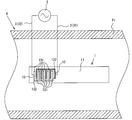
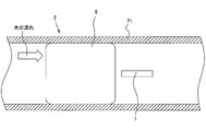
- FIG. 1 is a view showing a purification device according to the present invention
- FIG. 2 is an enlarged view of a periphery of a piezoelectric vibrator of the purification device shown in FIG.
- the purification device A according to the present invention generates bubbles (hereinafter referred to as microbubbles MB) having a diameter of several tens to several hundreds of ⁇ m in the water flowing inside the pipe Pi, and deposits accumulated on the inner surface of the pipe Pi. It decomposes and removes contaminants such as bacteria generated in water. More specifically, unlike normal bubbles, the microbubble MB has a characteristic of being crushed in water. The microbubble MB peels off deposits from the inner surface of the pipe Pi with energy (pressure) when crushing, or decomposes contaminants such as bacteria into minute and harmless minute substances (organic matter or inorganic matter). .
- energy pressure
- the micro vibrator MB is generated in the water inside the pipe Pi by driving the piezoelectric vibrator 1.
- the piezoelectric vibrator 1 is an element that generates a surface acoustic wave when a voltage is applied, and a gas (oxygen, nitrogen, etc.) in which the surface acoustic wave generated by the piezoelectric vibrator 1 is dissolved in water inside the pipe.
- Microbubble MB is generated by cavitation.
- the purifier A connects the piezoelectric vibrator 1 disposed in the pipe Pi, an AC power source 2 that applies a voltage to the piezoelectric vibrator 1, and the piezoelectric vibrator 1 and the AC power source 2.
- the signal line 3 is provided.
- the AC power supply 2 is disposed outside the pipe Pi.
- the piezoelectric vibrator 1 is supported inside a pipe Pi by a support member (not shown) so that surface acoustic wave vibration can be transmitted to water flowing inside the pipe Pi.
- the signal line 3 is an electric wire that connects the piezoelectric vibrator 1 and the AC power source 2 and is disposed so as to penetrate the pipe Pi.
- the signal line 3 may be wired inside the support member that supports the piezoelectric vibrator 1, or may be wired by providing a through hole in the pipe Pi so as to penetrate and waterproofing.
- the piezoelectric vibrator 1 includes a piezoelectric substrate 11 made of a piezoelectric material and a pair of comb-like electrodes 12 and 13 formed on the piezoelectric substrate 11.
- the comb-like electrode 12 is hatched for easy understanding.
- the piezoelectric material forming the piezoelectric substrate 11 is a material that contracts or expands when a voltage is applied. Examples of the piezoelectric material include LiNbO3 (lithium niobate), PZT (lead zirconate titanate), and the like.
- the comb-like electrode 12 and the comb-like electrode 13 formed on the piezoelectric substrate 11 have the same shape.
- the comb-shaped electrode 12 has five long comb-tooth portions 121 arranged in parallel at equal intervals, and a long connecting portion that connects the ends of the five comb-tooth portions 121 together. 122.
- the comb-teeth electrode 13 includes five long comb-teeth portions 131 that are arranged at equal intervals, and a long joint portion 132 that joins the ends of the comb-teeth portions 131 together. It has.
- the comb-teeth electrode 12 and the comb-teeth electrode 13 are formed on the piezoelectric substrate 11 so as to face each other, and a comb-teeth portion 131 is disposed in a gap between adjacent comb-teeth portions 121. That is, the comb-shaped electrodes 12 and 13 are formed so that the comb-tooth portion 121 and the comb-tooth portion 131 face each other and are alternately arranged.
- independent signal lines 3 are connected to the comb-like electrodes 12, 13, respectively, and an AC voltage is applied to the comb-like electrodes 12, 13.
- an AC voltage having a constant period is applied to the comb-shaped electrodes 12 and 13 from the AC power supply 2
- the voltage between the comb-tooth part 121 and the comb-tooth part 131 changes at a constant period. Due to this voltage change, the portion of the piezoelectric substrate 11 between the comb tooth portion 121 and the comb tooth portion 131 contracts or expands, and a surface acoustic wave is generated on the surface of the piezoelectric substrate 11.
- the surface acoustic wave generated on the surface of the piezoelectric substrate 11 is transmitted to the water inside the pipe Pi as surface acoustic wave vibration, and microbubbles MB are generated by causing cavitation on the surface of the piezoelectric substrate 11.
- a high frequency voltage (several MHz or more) is applied to the comb teeth 121 and the comb teeth 131.
- a pulsed DC voltage may be applied. In a configuration in which a pulsed DC voltage is applied, one of the comb-shaped electrodes 121 and 131 may be grounded and a pulsed DC voltage may be applied to the other.
- microbubble MB has a very slow ascent rate in water and tends to spread inside the piping due to the flow of water.
- the piezoelectric vibrator 1 that is a generation source of the microbubble MB is disposed at the center of the pipe Pi in order to distribute the microbubble MB inside the pipe Pi.
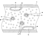
- FIG. 3 is a diagram schematically showing microbubbles and contaminants generated in the pipe.
- the sediment Dp and the bacteria Sb are illustrated as representative examples of the pollutant.
- the present invention is not limited to these, and suspended substances floating in water are also pollutants. is there. Further, the relative sizes of the pollutant and the microbubble are different from the actual ones.
- the microbubble MB is normally negatively charged, and the microbubble MB adheres to the surface of the deposit Dp and the bacteria Sb. As described above, the microbubble MB has a property of being crushed in water, and the microbubble MB attached to the deposit Dp peels the deposit Dp from the inner surface of the pipe Pi with energy (pressure) when crushing.
- microbubble MB adhering to the deposit Dp and the bacteria Sb decomposes the deposit Dp and the bacteria Sb with energy when crushing.
- the decomposed deposits Dp and bacteria Sb are further finely decomposed by the microbubbles MB generated one after another, and finally decomposed into harmless minute substances and removed together with running water.
- the purification apparatus of the present invention uses microbubbles to decompose (detoxify) and remove contaminants such as sediment Dp and bacteria Sb, the purification apparatus using chemical substances such as cleaning agents and disinfectants Thus, it is not necessary to separately use an apparatus for removing chemical substances, and the configuration can be simplified accordingly.
- a voltage for generating the inverse piezoelectric effect (deformation is generated by applying a voltage) of the piezoelectric material is merely applied to the piezoelectric substrate 11 and is applied as compared with a device that decomposes pollutants by underwater discharge. The voltage can be greatly reduced. Thereby, it is possible to simplify a device for supplying a voltage and a countermeasure for electric leakage, and the device itself can be simplified. Furthermore, since replacement members, such as a filter, can be reduced, long-term continuous operation is possible.
- FIG. 4 is a view showing another example of the purification device according to the present invention.
- the purification device B has the same configuration as the purification device A except that it includes three piezoelectric vibrators 1, and substantially the same parts are denoted by the same reference numerals. is there. Detailed descriptions of substantially the same parts are omitted.
- three piezoelectric vibrators 1 are arranged inside the pipe Pi in a direction intersecting with the direction of water flow.
- the three piezoelectric vibrators 1 are driven simultaneously, whereby microbubbles MB are generated around the piezoelectric vibrators 1.
- the piezoelectric vibrator 1 is one like the purification device A, In comparison, many microbubbles MB are generated. As a result, the concentration of the microbubbles MB is likely to increase, and the ability to decompose and remove contaminants can be exhibited in a short time after the piezoelectric vibrator 1 is driven.
- the concentration of the microbubble MB can be increased in such a short time, when the state of the water flowing in the pipe Pi deteriorates (for example, when the concentration of a predetermined contaminant is higher than a certain level). ) Can also be controlled to drive the piezoelectric vibrator 1. Even in this case, the purification device B can decompose and remove the contaminants contained in the water flowing through the pipe Pi in a short time. Further, since the purification device B stops the piezoelectric vibrator 1 until the inside of the pipe Pi reaches a certain condition, energy consumption can be reduced.
- the concentration of microbubbles MB becomes higher.
- the microbubbles MB easily reach every corner even near the piezoelectric vibrator 1 in the pipe Pi, and even if the pipe Pi where the purifier B is arranged is short, the effect of decomposing and removing the contaminants It is possible to increase.
- the purification device B can be driven and controlled so as to change the number of piezoelectric vibrators 1 to be driven in accordance with the flow rate of water flowing in the pipe Pi and the concentration of contaminants.
- the purification device B can be driven and controlled so as to change the number of piezoelectric vibrators 1 to be driven in accordance with the flow rate of water flowing in the pipe Pi and the concentration of contaminants.
- only one piezoelectric vibrator 1 (usually the one at the center) is driven, and when the flow velocity becomes high and the microbubbles MB are immediately washed away, or the deposits Dp and bacteria Sb.
- the concentration of such contaminants is high, it is possible to drive the remaining piezoelectric vibrator 1 in accordance with the flow rate and the concentration of the contaminants.
- the concentration of the microbubbles MB can be suppressed from being too high or too low.
- the three piezoelectric vibrators 1 are supported inside the pipe Pi in a direction orthogonal to the water flow direction, but the invention is not limited thereto.
- the microbubbles MB may be arranged so that they can be generated efficiently and effectively. Further, the number is not limited to three, and may be two or more than three.
- the purification device B it is assumed that a plurality of piezoelectric vibrators 1 are arranged side by side so that the microbubbles MB can spread uniformly (substantially uniformly) inside the pipe Pi even in the vicinity of the piezoelectric vibrator 1. it can.
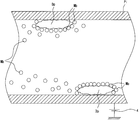
- FIG. 5 is a diagram showing another example of the purification device according to the present invention
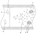
- FIG. 6 is a diagram showing the action of microbubbles in the purification device shown in FIG.
- the pipe Pi shown in FIG. 5 is a pipe having conductivity
- the purification device C includes a voltage application unit 4 that applies a DC voltage as a charging device that charges the pipe Pi with a positive charge.
- the voltage application unit 4 has been described by taking a DC power supply as an example.
- the voltage application unit 4 is not limited to this, and a wide range of applications that can apply a positive DC voltage to the pipe Pi are used. can do.
- the microbubble MB is pulled toward the pipe Pi by applying a positive DC current to the pipe Pi (see FIG. 5). Since the micro bubbles MB are pulled toward the pipe, most of the micro bubbles MB generated in the piezoelectric vibrator 1 adhere to the deposit Dp adhering to the inner surface of the pipe Pi, and the deposit Dp is removed from the inner surface of the pipe Pi. While peeling, it decomposes (see FIG. 6).
- the purification device C is configured to adsorb most of the generated microbubbles MB on the inner surface of the pipe Pi, so that the bacteria Sb is hardly generated and the deposit Dp is easily deposited on the inner surface of the pipe Pi.
- the pipe Pi Even if the pipe Pi is not electrically conductive, a positive charge attracting the microbubble MB is charged on the entire pipe Pi or the inner surface side of the pipe Pi by a well-known method such as static electricity or dielectric polarization. It is possible to obtain the same effect by using the method. Conversely, the pipe Pi may be negatively charged. By negatively charging the pipe Pi, the pipe Pi and the microbubble MB are repelled, and as a result, the concentration of the microbubble MB can be increased at the center of the pipe Pi.
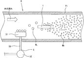
- FIG. 7 is a view showing still another example of the purification apparatus according to the present invention.
- the purification device D has the same configuration as the purification device A except that it includes a bubbling portion 5 that generates bubbles, and substantially the same parts are denoted by the same reference numerals.
- the purification device D includes a bubbling unit 5 that generates bubbles on the upstream side of the piezoelectric vibrator 1 in the water flow direction.
- the bubbling unit 5 supplies air outside the pipe Pi to the water flowing inside the pipe Pi as bubbles BL having a diameter larger than that of the microbubble MB.
- the bubbling unit 5 includes a bubble generation unit 51 disposed inside the pipe Pi, and a pump 52 that sends air to the bubble generation unit 51.
- the bubble generating unit 51 and the pump 52 are connected by a pipe 50.
- the bubble generating part 51 is formed of a porous material (so-called porous material) such as ceramics.
- the material which can generate a bubble can be widely employ
- the bubble BL flows toward the piezoelectric vibrator 1 along the flow of water.
- Surface acoustic wave vibration propagates in the water around the piezoelectric vibrator 1, and the bubble BL is refined by the surface acoustic wave vibration, whereby microbubbles MB are generated.
- the bubbling portion 5 for example, when the water in which the gas is not dissolved is flowing into the pipe Pi due to high temperature or low pressure, the inside of the pipe Pi It is possible to generate microbubbles MB having a certain concentration or higher in flowing water.
- the bubble BL generated from the bubble generation part 51 of the bubbling part 5 has a high rising speed in water unlike the microbubble MB.
- the bubble generating unit 51 is disposed below the piezoelectric vibrator 1. Further, the difference in height between the bubble generating part 51 and the piezoelectric vibrator 1 is also affected by the flow velocity of the water flowing through the pipe Pi. That is, it is preferable that the relationship is such that most of the bubbles BL generated in the bubble generation unit 51 and riding on the water flow can reach the region where the surface acoustic wave vibration from the piezoelectric vibrator 1 is propagated. .
- the gas supplied from the bubbling unit 5 is exemplified by the air outside the pipe Pi fed by the pump 52 arranged outside the pipe Pi, but is not limited thereto.
- the supply gas when the microbubbles MB are crushed, hydroxyl radicals with high oxidation potential can be generated, and organic substances such as bacteria can be decomposed at the molecular level. It is also possible to adjust the pH of the water flowing through the pipe Pi with the supplied gas.
- FIG. 8 is a diagram showing still another example of the purification device according to the present invention
- FIG. 9 is a diagram showing the action of microbubbles in the purification device shown in FIG.
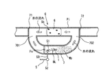
- the purification device E includes a filter 6 on the upstream side (left side in the figure) of the piezoelectric vibrator of the pipe Pi. Except for the filter 6, it has the same configuration as the purification device A shown in FIG. 1, and substantially the same parts are denoted by the same reference numerals.
- the purification device is disposed in a part of the piping of a device having a pipe through which water passes.
- the foreign substance Ob for example, a metal piece or the like
- the foreign substance Ob that cannot be decomposed by the microbubble MB in the piping. May flow in.
- this non-decomposable foreign substance Ob flows into the purification device, it adheres to the piezoelectric vibrator 1 or a support member that supports the piezoelectric vibrator 1 and interferes with the operation of the piezoelectric vibrator 1, or the piezoelectric vibrator 1 Or the surface acoustic wave generated in the water is prevented from being transmitted into the water as surface acoustic wave vibration. That is, when the foreign object Ob adheres to the piezoelectric vibrator 1 or the support member, the effect of the purification device is reduced.
- the filter 6 is disposed on the upstream side of the piezoelectric vibrator 1 so that the foreign object Ob that obstructs the operation of the piezoelectric vibrator 1 does not approach the piezoelectric vibrator 1 (see FIG. 9).
- the piezoelectric vibrator 1 can stably generate the microbubbles MB, and the bacteria Sb and the deposits are decomposed into harmless minute substances by the microbubbles MB.
- the filter 6 is coarse enough to be caught by the foreign matter Ob, so that clogging hardly occurs and the frequency of replacement of the filter 6 can be reduced. That is, it is possible to reduce the time and effort required for operation compared to a purification device in which small contaminants such as conventional bacteria Sb are also removed by a filter.
- the deposit formed by depositing the substance that has passed through the filter 6 on the inner surface on the downstream side of the pipe Pi can be separated from the inner surface of the pipe with the microbubbles MB and decomposed into harmless fine substances. Therefore, it is possible to suppress the deterioration of the water flow in the pipe Pi.
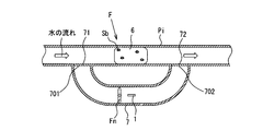
- FIG. 10 is a diagram showing a normal operation state of the purification device according to the present invention
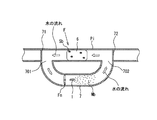
- FIG. 11 is a diagram showing a filter purification operation state of the purification device shown in FIG.
- the purification apparatus F shown in FIGS. 10 and 11 includes a filter 6 disposed inside a main pipe Pi through which water flows during normal operation, and a loop pipe 7 provided alongside the main pipe Pi.
- the filter 6 is used to stop the contaminants such as bacteria and reactants generated in the water flowing in the main pipe Pi during normal operation from flowing, or to prevent non-woven fabric, porous material, etc. Although water can pass, it is formed with a gap that suppresses the passage of contaminants.
- the loop pipe 7 is connected to the upstream side and the downstream side of the filter 6 of the main pipe Pi, and the upstream side switching valve 71 and the downstream side switching valve 72 are arranged in the openings 701 and 702 which are the respective connecting portions.
- the upstream switching valve 71 and the downstream switching valve 72 are electrically operated using a solenoid (not shown).
- the upstream side switching valve 71 is a valve that operates so as to open one of the openings 701 on the upstream side and the upstream side of the main pipe Pi and close the other.
- the downstream side switching valve 72 is a valve that operates to open one of the downstream side opening 702 and the downstream side opening 702 of the main pipe Pi.
- the upstream side and downstream side switching valves 71 and 72 are shown to have an open / close lid, but are diagrams for schematically showing the flow of water in the piping. The actual configuration is different. Moreover, although the solenoid is used for operation
- the flow generation unit Fn is a device for generating a water flow in a closed pipeline formed by the main pipe Pi and the loop pipe 7.
- the flow generation unit Fn is centered on the same axis as the central axis of the loop pipe 7. It is the structure provided with the propeller which rotates.
- the flow generation part Fn is not limited to this, The thing of the structure which can generate
- the flow velocity (pressure) of the water flow generated in the flow generator Fn is such that water can be circulated through the closed pipe line formed by the main pipe Pi and the loop pipe 7, that is, the water flow is filtered 6. And a flow rate (pressure) at which the microbubbles MB can decompose the contaminants attached to the filter 6.
- the upstream side switching valve 71 and the downstream side switching valve 72 close the openings 701 and 702 from the main pipe Pi to the loop pipe 7. Thereby, water flows from the left to the right through the main pipe Pi. At this time, the water flowing through the main pipe Pi passes through the filter 6 from the left to the right, pollutants such as organic matter and bacteria Sb are caught on the filter 6, and the water from which the pollutants have been removed flows downstream.
- the contaminants adhering to the filter 6 are adhering to the upstream side of the main pipe Pi, and to the left side in FIGS.
- control is performed to stop the flow of water from the upstream. That is, when the purification operation using the normal filter 6 is completed, the water flow is stopped.
- the purification device F performs a filter purification operation for decomposing the contaminants attached to the filter 6 while the water flow is stopped.
- the filter purification operation in the purification device F when performing the filter purification operation, first, the upstream side switching valve 71 and the downstream side switching valve 72 are driven, and the upstream side and the downstream side of the main pipe Pi are closed. Further, the upstream side and the downstream side of the main pipe Pi are closed, so that the loop pipe 7 and the main pipe Pi are communicated. That is, as shown in FIG. 11, the loop pipe 7 is connected to the upstream side and the downstream side of the portion where the filter 6 of the main pipe Pi is disposed, and is closed by the main pipe Pi and the loop pipe 7. A conduit is formed. Thereafter, in the purification device F, the flow generator Fn and the piezoelectric vibrator 1 are driven.
- the flow generation unit Fn generates a water flow so that the water flows from the downstream side to the upstream side during normal operation of the filter 6. That is, the flow generation unit Fn generates a water flow toward the downstream opening 702 in the loop pipe 7. Due to the water flow generated by the flow generation unit Fn, the water inside the pipe flows through the inside of the loop pipe 7 toward the downstream opening 702 and flows into the main pipe Pi from the downstream opening 702. In the main pipe Pi, since the downstream pipe is closed by the downstream switching valve 72, the water flow is directed to the main pipe Pi upstream. The water flow passes through the filter 6 from the downstream side toward the upstream side during normal operation.
- the piezoelectric vibrator 1 is driven simultaneously or substantially simultaneously with the driving of the flow generation unit Fn.
- microbubbles MB are generated from the periphery of the piezoelectric vibrator 1 in the water flow.
- the microbubbles MB generated around the piezoelectric vibrator 1 are swept away by the water flow generated by the flow generation unit Fn, and flow into the filter 6 disposed in the main pipe Pi together with the water flow.
- the pollutant adhering to the filter 6 is decomposed by the pressure (energy) when the microbubble MB is crushed, and becomes a harmless minute substance.
- the contaminants adhering to the filter 6 may be caused to flow upstream of the filter 6 by the water flow.
- the microbubbles MB also adhere to the contaminants separated from the filter 6.
- the pollutant to which the microbubble MB adheres is decomposed by the pressure (energy) at the time of the collapse of the microbubble MB, and becomes a harmless minute substance.
- the upstream side switching valve 71 and the downstream side switching valve 72 are driven, and the upstream side opening 701 and the downstream side opening 702 are closed.
- the upstream pipe line and the downstream pipe line of the main pipe Pi are opened.
- harmless minute substances generated by decomposing the contaminants by the filter purification operation flow along the flow of water.
- the minute substance passes through the gap of the filter 6 and flows downstream of the purification device F.
- the filter 6 after the filter purification operation is caught by a substance that could not be decomposed even in the filter purification operation using the microbubble MB.
- substances that cannot be decomposed by the filter purification operation gradually accumulate on the filter 6, so that the filter 6 needs to be replaced.
- the filter 6 since the contaminants are decomposed by the filter purification operation, the filter 6 must be replaced. The frequency can be reduced, and the operation time can be reduced accordingly.
- FIG. 12 is a view showing still another example of the purification device according to the present invention.
- the purification device G shown in FIG. 12 has the same shape as the purification device F shown in FIGS. 10 and 11 except that it includes the bubbling portion 5, and substantially the same parts are denoted by the same reference numerals. In addition, detailed description of substantially the same parts is omitted.
- the purification device G includes a bubbling portion 5 inside the loop pipe 7.
- the bubbling unit 5 since the bubbling unit 5 is provided, air is sent from the outside to the internal water during the filter purification operation, so that the concentration of the microbubble MB can be increased.
- the bubbling unit 5 is stopped when the upstream opening 701 and the downstream opening 702 are closed. Thereby, it is possible to suppress energy consumption.
- the bubbling unit 5 is disposed downstream of the flow generation unit Fn in the loop pipe 7, but is not limited thereto, and the bubbling unit 5 is disposed upstream of the flow generation unit Fn. You may arrange.
- the flow generation unit Fn is a propeller type
- the bubbles BL generated in the bubbling unit 5 are sheared by the propeller to become small bubbles BL, so that the diameter of the microbubbles MB generated in the piezoelectric vibrator 1 can be reduced.
- the bubbling part 5 and the flow generation part Fn may be formed integrally.
- the piezoelectric vibrator 1 and the flow generation unit Fn may be integrally formed.
- the piezoelectric vibrator 1 and the flow generation unit Fn are integrated, it is possible to save the trouble of attaching the member, and it is possible to reduce the cost for assembly.
- the piezoelectric vibrator 1 may be incorporated in a part of the propeller.
- FIG. 13 is a diagram showing a normal operation state of still another example of the purification device according to the present invention
- FIG. 14 is a diagram showing a filter purification operation state of the purification device shown in FIG.
- the purification device H shown in FIG. 13 has the same configuration as the purification device F except for the place where the piezoelectric vibrator 1 is installed, and substantially the same parts are denoted by the same reference numerals.
- the piezoelectric vibrator 1 is disposed downstream of the filter 6 of the main pipe Pi and upstream of the downstream opening 702.
- the filter 6 is a filter for separating a foreign substance Ob (for example, a metal piece or the like) that cannot be decomposed by the microbubble MB from the water flow, like the purification device E shown in FIG. 8. That is, contaminants such as bacteria Sb pass through the filter 6, but are decomposed into harmless minute substances by the microbubbles MB generated from the piezoelectric vibrator 1 provided downstream of the filter 6. Thereby, the water which passed the purification apparatus H flows downstream in the state from which the foreign material Ob and the contaminant were removed.
- a foreign substance Ob for example, a metal piece or the like
- the upstream switching valve 71 and the downstream switching valve 72 are driven and closed by the main piping Pi and the loop piping 7 as shown in FIG. A pipe is formed, and the flow generator Fn disposed in the loop pipe 7 is driven to generate a water flow passing through the filter 6 from the downstream side to the upstream side. A water flow is generated that circulates in a closed pipe line formed by the main pipe Pi and the loop pipe 7.
- the piezoelectric vibrator 1 While the water flow that circulates in the closed pipe line formed by the main pipe Pi and the loop pipe 7 is generated, the piezoelectric vibrator 1 is driven and the microbubble MB continues to be generated.
- the microbubbles MB generated by the piezoelectric vibrator 1 are caused to flow into the water flow. That is, the microbubbles MB can pass through the filter 6 from the downstream side, and decompose contaminants such as bacteria Sb adhering to the filter 6 into harmless minute substances.
- the upstream switching valve 71 and the downstream switching valve 72 are operated, and the upstream opening 701 and the downstream opening 702 are closed.
- the minute substance decomposed by the water flow when the purification device H is normally operated passes through the filter 6 and flows downstream.
- the filter purification operation since the filter purification operation is performed, occurrence of clogging of the filter 6 can be suppressed, and the replacement frequency of the filter 6 can be suppressed.
- Each of the purification devices provided with the loop pipe 7 described above is provided with a flow generating section that generates a water flow in a closed pipe line by rotating the propeller by the main pipe Pi and the loop pipe 7.
- a water flow may be generated by another method (for example, a bubbling portion is arranged inside a vertically arranged pipe)
- the flow generating portion may be omitted. What is necessary is just to be able to generate a water flow inside the piping.
- the piezoelectric vibrator 1 is disposed inside the pipes Pi and 7 independently of the pipes Pi and 7, but is not limited thereto, and contacts the inner surfaces of the pipes Pi and 7. (Or integrally).
- the signal line 3 may not be wired inside the pipes Pi and 7.
- positioned inside piping Pi and 7 can be reduced, it is also possible to suppress generation
- water is used as the fluid flowing in the pipe, but the present invention is not limited to this.
- a substance that becomes liquid at room temperature or a predetermined temperature a substance that is a mixture of water and other substances, a substance in which a substance is dissolved in water, and the like can be given.
- the purification device according to the present invention can be used for a device such as a washing machine, a water purifier, a water heater, etc., in which a liquid such as water flows, and a product generated or mixed in the liquid such as water flowing in the piping. It can be used as a purification device for decomposing and removing contaminants such as bacteria.
- a to H Purification Device 1 Piezoelectric Vibrator 11 Piezoelectric Substrate 12 Comb Tooth Electrode 121 Comb Tooth 122 Connection Unit 13 Comb Tooth Electrode 131 Comb Tooth 132 Connection Unit 2 AC Power Supply 3 Signal Line 4 Voltage Application Unit 5 Bubbling Unit 50 Pipe 51 Bubble supply section 52 Pump 6 Filter 7 Loop piping 701 Upstream opening 702 Downstream opening 71 Upstream switching valve 72 Downstream switching valve Pi Piping (main piping) Fn flow generator
Landscapes
- Engineering & Computer Science (AREA)
- Mechanical Engineering (AREA)
- Life Sciences & Earth Sciences (AREA)
- Hydrology & Water Resources (AREA)
- Environmental & Geological Engineering (AREA)
- Water Supply & Treatment (AREA)
- Chemical & Material Sciences (AREA)
- Organic Chemistry (AREA)
- Physical Water Treatments (AREA)
Abstract
小型で構造が簡単であるとともに運用が容易であり、さらに環境負荷を小さくするため、浄化装置Aは、電源2と、配管Pi内部に配置され、電圧が印加されることで弾性表面波を発生し、周囲の液体を振動させてマイクロバブルMBを発生させる圧電振動子1とを備えている。
Description
本発明は、配管内部の堆積物や内部を流れる水に含まれる細菌などを分解、除去する浄化装置に関するものである。
水を循環させる又は排水する設備を備えた装置において、配管内部に汚染物質が混入したり、前記配管内部を流れる水に汚染物質が発生したりし、前記配管の内壁に付着することで表面堆積物を形成することがある。前記汚染物質が細菌等の場合、前記配管の内部で増殖し、前記配管内部が衛生的に劣悪な環境となる。また、前記汚染物質が無害な物質であったとしても、前記配管の内壁に堆積することで、前記配管の水が流動する部分の面積が減少し、圧力の上昇(流量の低下)等の原因となる。
このような、前記配管を流れる水の環境の悪化や圧力上昇(流量低下)を解消するため、前記配管内部に流れる水にフィルタを用いてろ過し、前記汚染物質を除去する方法がある。このようなフィルタを用いて水をろ過する方法の場合、前記フィルタは目詰まりするため定期的な交換が必要であり、メンテナンスの手間とコストが必要である。また、前記配管内を流れる水に汚染物質を化学的に分解する洗浄剤を混入し、前記汚染物質を分解、除去する方法も考えられるが、前記洗浄剤を含む水は環境負荷が大きく、廃液処理が必要となる。また、廃液処理が必要であるので、水を循環させる装置に採用することは困難である。
そこで、特開2010-179206号公報には、配管内部に一対の電極を設け、電極間に電圧を印加して放電することで、前記汚染物質を放電分解処理する浄化装置が開示されている。このような、流水中に含まれる前記汚染物質を放電分解処理する浄化装置の場合、前記フィルタのような定期的な交換が必要な部材は無く、前記洗浄剤が含まれる水の廃液処理も不要である。
また、特開2007-136275号公報には、洗浄槽内にインゼクター配置し、インゼクターよりポンプで供給された水とエアーと混合して噴出することでマイクロバブルを発生させ、被洗浄物にマイクロバブルを含む水を吹きかけ、前記被洗浄物の表面に付着した油分等の汚れを除去する洗浄装置が開示されている。
特開2010-179206号公報に記載の浄化装置では、汚染物質を放電分解処理するので、汚染物質を取り除き、水を再生させる機構が不要である。しかしながら、水中に配置された電極の間に放電が発生する程度の大きな電位差(数kV)が必要であり、エネルギの消費量が多くなるとともに、運用に高度な技術を要する。また、大電力を供給するための大きな装置が必要であり、漏電時の危険性も高くなる。
また、特開2007-136275号公報に記載の洗浄装置では、洗浄装置にインゼクター、前記インゼクターにエアー及び水を供給する装置を配置しなくてはならず、構成が複雑になる。
そこで本発明は、小型で構造が簡単であるとともに運用が容易であり、さらに環境負荷が小さい浄化装置を提供することを目的とする。
上記目的を達成するために本発明は、配管内部を流れる液体を浄化する浄化装置であって、電源と、前記配管内部に配置され、前記電源より電圧が印加されることで、弾性表面波を発生し、周囲の液体を振動させてマイクロバブルを発生させる圧電振動子とを備えている。
この構成によると、前記圧電振動子と前記電源とを備える構成であり、構成が簡単である。また、マイクロバブルが液体中で圧壊するときのエネルギ(圧力)で、細菌、浮遊物等の分解を行ったり、配管の内面に堆積した堆積物を剥離分解したりして、無害な微小物質に変換するので、運用が容易である。また、例えば、液体が水の場合、前記水の中に含まれるガス(酸素、窒素)を表面弾性波によるキャビテーションでマイクロバブル化しているので、環境を悪化させるものが含まれておらず、また、汚染物質も無害な微小物質に変換されることから、環境に対する負荷も小さくなる。なお、前記圧電振動子に印加される電圧として、高周波の交流電圧や、パルス状のもの(直流を含む)を挙げることができる。
なお、前記圧電振動子として、圧電材料で形成された圧電基板と、前記圧電基板に形成され、前記電源より電圧が印加される一対の櫛歯状電極とを備える構成としてもよい。また、前記圧電振動子が複数個備えられており、前記圧電振動子が、前記配管内の液体が流れる方向と交差する方向に並んで配置されていてもよい。この構成によると、前記櫛歯状電極の構成(櫛歯状電極の櫛歯状部の間隔)を適切に調整することで、発生する表面弾性波の波長を調整することができ、マイクロバブルの直径を調整することが可能である。
上記構成において、前記配管に正の電荷を帯電させる帯電装置を備えていてもよい。また、前記配管が導電性を有する材料で形成されているとき、前記帯電装置が前記配管に正の電圧を印加する電圧印加部である。
この構成によると、前記圧電振動子で発生したマイクロバブルは通常、負に帯電するので、正の電荷を帯電された配管に引っ張られ、前記マイクロバブルが配管の内面に集中する。例えば、配管の内部に堆積物を発生させやすい性質の液体を流す場合にマイクロバブルを配管の内面に集中させることができるので、浄化効果を高めることが可能である。
上記構成において、前記配管の前記圧電振動子の上流側内部には、配管を流れる液体に気体を供給するバブリング部が備えられている。なお、前記バブリング部は前記配管内部に配置された気泡供給部と、前記配管の外に配置されたポンプと、前記気泡供給部と前記ポンプとをつなぐパイプとを備え、前記配管の内部を流れる液体に前記配管の外部の空気を供給しているものであってもよく、前記配管の内部に流れる液体にオゾンを供給するものであってもよい。
この構成によると、前記液体にマイクロバブルを発生させるためのガスが十分に溶解していない場合であっても、細菌、浮遊物、堆積物等の分解、除去を行うことができる程度の濃度のマイクロバブルを発生することができる。また、オゾンを供給することで、マイクロバブルが圧壊するときに、酸化ポテンシャルの高い水酸基ラジカルを発生するので、有機物を分子レベルまで分解することが可能である。
上記構成において、前記配管の内部には、フィルタが配置されている。なお、この場合、前記圧電振動子が前記フィルタの下流側に配置されていてもよい。前記フィルタによるろ過と、マイクロバブルによる分解とを併用することで、前記フィルタを通過する小さな物質は前記マイクロバブルによって無害な微小物質に分解し、逆にマイクロバブルでは分解できない大きな物質は前記フィルタで取り除くことができる。
上記構成において、前記配管には前記フィルタの上流側と下流側とを直接つなぐループ配管と、前記配管のループ配管の上流及び下流とを閉鎖する上流側切替弁及び下流側切替弁とを有しており、前記上流側切替弁及び前記下流側切替弁とが前記配管の上流側及び下流側を閉じることで、前記配管と前記ループ配管とが閉じた管路を形成し、前記圧電振動子が前記閉じた管路の内部に配置されている。
上記構成において、前記上流側切替弁及び前記下流側切替弁は、前記配管の上流側及び下流側と、前記配管と前記ループ配管とをつなぐ開口とのいずれか一方を閉じるように動作する切替弁である。
上記構成において、前記ループ配管には、前記閉じた管路内を循環し、前記フィルタを下流側から上流側に通過する流れを発生させる流れ発生部を備えている。
本発明によると、小型で構造が簡単であるとともに運用が容易であり、さらに環境負荷が小さい浄化装置を提供することができる。
以下に本発明の実施形態について図面を参照して説明する。図1は本発明にかかる浄化装置を示す図であり、図2は図1に示す浄化装置の圧電振動子の周囲を拡大した図である。本発明にかかる浄化装置Aは、配管Piの内部を流れる水中に直径数十μm~数百μm程度の気泡(以下、マイクロバブルMBという)を発生させ、配管Piの内面に堆積した堆積物や水中で発生した細菌等の汚染物質を分解除去するものである。詳しく説明すると、マイクロバブルMBは通常の気泡と異なり、水中で圧壊する特性を有している。そして、マイクロバブルMBは、圧壊するときのエネルギ(圧力)で堆積物を配管Piの内面より引き剥がしたり、細菌等の汚染物質を微小で無害な微小物質(有機物又は無機物)に分解したりする。
図1に示すように、浄化装置Aでは、圧電振動子1を駆動することで、配管Piの内部の水にマイクロバブルMBを発生させている。圧電振動子1は電圧が印加されることで、表面弾性波を発生する素子であり、圧電振動子1で発生した表面弾性波が配管内部の水に溶存している気体(酸素、窒素等)からキャビテーションによりマイクロバブルMBを発生させている。
(第1実施形態)
図2を参照して浄化装置の具体的な構成を説明する。図2に示すように、浄化装置Aは、配管Pi内に配置された圧電振動子1と、圧電振動子1に電圧を印加する交流電源2と、圧電振動子1と交流電源2とを接続する信号線3とを備えている。図2に示しているように、交流電源2は配管Piの外部に配置されている。なお、圧電振動子1は不図示の支持部材によって配管Piの内部に、配管Pi内部を流れる水に表面弾性波振動を伝達できるように支持されている。信号線3は圧電振動子1と交流電源2とをつなぐ電線であり、配管Piを貫通するように配置される。この信号線3は、圧電振動子1を支持する支持部材の内部に配線するようにしてもよく、配管Piに貫通孔を設け、貫通させるとともに防水処理を行って配線されていてもよい。
図2を参照して浄化装置の具体的な構成を説明する。図2に示すように、浄化装置Aは、配管Pi内に配置された圧電振動子1と、圧電振動子1に電圧を印加する交流電源2と、圧電振動子1と交流電源2とを接続する信号線3とを備えている。図2に示しているように、交流電源2は配管Piの外部に配置されている。なお、圧電振動子1は不図示の支持部材によって配管Piの内部に、配管Pi内部を流れる水に表面弾性波振動を伝達できるように支持されている。信号線3は圧電振動子1と交流電源2とをつなぐ電線であり、配管Piを貫通するように配置される。この信号線3は、圧電振動子1を支持する支持部材の内部に配線するようにしてもよく、配管Piに貫通孔を設け、貫通させるとともに防水処理を行って配線されていてもよい。
圧電振動子1は、圧電材料で形成された圧電基板11と、圧電基板11に形成された一対の櫛歯状電極12、13とを備えている。なお、図2では、理解を容易にするため櫛歯状電極12にハッチングを施している。圧電基板11を形成する圧電材料は、電圧が印加されることで収縮又は膨張する材料である。圧電材料として、例えば、LiNbO3(ニオブ酸リチウム)、PZT(チタン酸ジルコン酸鉛)等を挙げることができる。
圧電基板11に形成された櫛歯状電極12及び櫛歯状電極13は、同一の形状を有している。櫛歯状電極12は等間隔で平行に並んで配置された長尺状の5本の櫛歯部121と、5本の櫛歯部121の端部をまとめて連結する長尺状の連結部122とを備えている。同様に、櫛歯状電極13は等間隔に並んで配置された長尺状の5本の櫛歯部131と、櫛歯部131の端部をまとめて連結する長尺状の連結部132とを備えている。櫛歯状電極12と櫛歯状電極13とは圧電基板11に、互いに対向するように形成されており、隣り合う櫛歯部121の隙間に櫛歯部131が配置されている。すなわち、櫛歯状電極12、13は、櫛歯部121と櫛歯部131とが対向するとともに、互いに交互に配置されるように形成されている。
また、櫛歯状電極12、13にはそれぞれ独立した信号線3(31、32)が接続されており、櫛歯状電極12、13には交流電圧が印加される。櫛歯状電極12、13に交流電源2から一定周期の交流電圧が印加されることで、櫛歯部121と櫛歯部131との間の電圧は一定周期で変化する。この電圧の変化によって、圧電基板11の櫛歯部121と櫛歯部131との間の部分が収縮又は膨張し、圧電基板11の表面に表面弾性波が発生する。この圧電基板11の表面で発生した表面弾性波が配管Pi内部の水に表面弾性波振動として伝達され、圧電基板11の表面でキャビテーションを起こすことでマイクロバブルMBが発生する。なお、表面弾性波振動で配管Pi内部の水がキャビテーションを起こすために、櫛歯部121及び櫛歯部131には高周波(数MHz以上)の電圧が印加される。また、上述の櫛歯状電極121、131には交流電圧が印加される例を示しているが、パルス状の直流電圧が印加されるものであってもよい。パルス状の直流電圧が印加される構成の場合、櫛歯状電極121、131の一方を接地し、他方にパルス状の直流電圧を印加する構成としてもよい。
そして、マイクロバブルMBは通常の気泡とは異なり、水中での上昇速度が極めて遅く、水の流れによって配管の内部に拡がりやすい。浄化装置Aでは、配管Piの内部にマイクロバブルMBをいきわたらせるため、マイクロバブルMBの発生源である圧電振動子1は配管Piの中心部に配置されている。
図3は配管内部に発生したマイクロバブルと汚染物質とを模式的に表した図である。なお、図3に示す配管では、汚染物質の代表例として、堆積物Dpと細菌Sbとを図示しているが、これらに限定されるものではなく、水中に浮遊する浮遊物質等も汚染物質である。また、汚染物質とマイクロバブルとの相対的な大きさは実際のものとは異なる。マイクロバブルMBは通常マイナスに帯電しており、マイクロバブルMBは堆積物Dpや細菌Sbの表面に付着する。上述したとおり、マイクロバブルMBは、水中で圧壊する性質があり、堆積物Dpに付着したマイクロバブルMBは、圧壊するときのエネルギ(圧力)で堆積物Dpを配管Piの内面より剥離させる。また、堆積物Dp及び細菌Sbに付着しているマイクロバブルMBは、圧壊するときのエネルギで堆積物Dp及び細菌Sbを分解する。分解された堆積物Dp、細菌Sbは次々に発生するマイクロバブルMBによって、さらに細かく分解され、最終的に無害な微小物質に分解され、流水とともに除去される。
本発明の浄化装置は、堆積物Dpや細菌Sb等の汚染物質を分解(無害化)、除去するのにマイクロバブルで行っているので、洗浄剤、消毒剤等の化学物質を用いる浄化装置のように、化学物質を除去する装置を別途用いなくてもよく、それだけ、構成を簡単にすることができる。また、圧電材料の逆圧電効果(電圧を印加することで変形を発生させる)を発生させるための電圧を圧電基板11に印加するだけであり、水中放電で汚染物質を分解する装置に比べて印加電圧を大幅に低く抑えることができる。これにより、電圧を供給する装置や漏電対策を簡易なものとすることができ、装置自体を簡略化することが可能である。さらに、フィルタ等の交換部材を減らすことができるので、長期間の連続稼動が可能である。
(第2実施形態)
本発明にかかる浄化装置の他の例について図面を参照して説明する。図4は本発明にかかる浄化装置の他の例を示す図である。図4に示すように、浄化装置Bは、圧電振動子1を3個備えている以外は、浄化装置Aと同じ構成を有しており、実質上同じ部分には、同じ符号が付してある。また、実質上同じ部分の詳細な説明は省略する。図4に示すように、浄化装置Bは、配管Piの内部に、水の流れる方向と交差する方向に並んで3個の圧電振動子1が配置されている。
本発明にかかる浄化装置の他の例について図面を参照して説明する。図4は本発明にかかる浄化装置の他の例を示す図である。図4に示すように、浄化装置Bは、圧電振動子1を3個備えている以外は、浄化装置Aと同じ構成を有しており、実質上同じ部分には、同じ符号が付してある。また、実質上同じ部分の詳細な説明は省略する。図4に示すように、浄化装置Bは、配管Piの内部に、水の流れる方向と交差する方向に並んで3個の圧電振動子1が配置されている。
浄化装置Bでは、3個の圧電振動子1が同時に駆動されることで、各圧電振動子1の周囲よりマイクロバブルMBが発生し、浄化装置Aのように圧電振動子1が1個の時に比べ、多くのマイクロバブルMBが発生する。これにより、マイクロバブルMBの濃度が、上昇しやすく、圧電振動子1の駆動後、短時間で汚染物質の分解、除去の能力を発揮することができる。
また、このように短時間でマイクロバブルMBの濃度を上げることができるので、配管Pi内を流れる水の状態が悪化したとき(例えば、予め決められた汚染物質の濃度が一定以上になったとき)に圧電振動子1を駆動する制御も可能である。この場合でも、浄化装置Bは、短時間で、配管Piを流れる水に含まれる汚染物質を分解、除去することが可能である。また、浄化装置Bは、配管Piの内部が一定の条件に達するまで、圧電振動子1を停止しているので、消費エネルギを削減することができる。
さらに、図4に示しているように、圧電振動子1を3個備えている浄化装置Bの場合、圧電振動子1が1個の場合に比べて、配管Piの圧電振動子1の下流近傍でのマイクロバブルMBの濃度が高くなる。浄化装置Bでは、配管Piの圧電振動子1の下流近傍でもマイクロバブルMBが隅々に行き渡りやすく、浄化装置Bが配置されている配管Piが短い場合でも、汚染物質を、分解、除去する効果を高めることが可能である。
さらに、浄化装置Bでは、配管Pi内部を流れる水の流速や汚染物質の濃度にあわせて駆動する圧電振動子1の個数を変更するように駆動制御することも可能である。例えば、通常の運転では、1個の圧電振動子1のみ(通常中央のもの)を駆動しておき、流速が速くなりマイクロバブルMBがすぐに流されてしまうときや、堆積物Dp及び細菌Sb等の汚染物質の濃度が高いときには、その流速や汚染物質の濃度にあわせて、残りの圧電振動子1を駆動することも可能である。このように、適宜駆動する圧電振動子1を切り換えることで、マイクロバブルMBの濃度が高すぎたり、低すぎたりするのを抑制することができる。これにより、駆動で消費されるエネルギ(電力)を抑えつつ、水を浄化するのに十分な濃度のマイクロバブルMBを発生させることができ、効率よく汚染物質を分解、除去できる。
なお、図4に示す浄化装置Bでは、配管Piの内部に3個の圧電振動子1が水の流れ方向と直交する方向に並んで支持されているが、それに限定されるものではなく、配管Pi内部の流速分布や圧力変動等を考慮して、マイクロバブルMBが効率よく、効果的に発生できるように配置されるものとしてもよい。また、3個に限定されるものではなく、2個でもよいし、3個を超える個数であってもよい。浄化装置Bとして、圧電振動子1の近傍でもマイクロバブルMBが配管Piの内部に均一(略均一)に拡がることができるように、複数個の圧電振動子1を並べて配置したものとすることができる。
(第3実施形態)
本発明にかかる浄化装置の他の例について図面を参照して説明する。図5は本発明にかかる浄化装置の他の例を示す図であり、図6は図5に示す浄化装置におけるマイクロバブルの作用を示す図である。図5に示す配管Piは導電性を有する配管であり、浄化装置Cには、配管Piに正の電荷を帯電させる帯電装置として、直流電圧を印加する電圧印加部4が備えられている。図5では、電圧印加部4として、直流電源を採用しているものを例に説明しているが、これに限定されるものではなく、配管Piに正の直流電圧を印加できるものを広く採用することができる。
本発明にかかる浄化装置の他の例について図面を参照して説明する。図5は本発明にかかる浄化装置の他の例を示す図であり、図6は図5に示す浄化装置におけるマイクロバブルの作用を示す図である。図5に示す配管Piは導電性を有する配管であり、浄化装置Cには、配管Piに正の電荷を帯電させる帯電装置として、直流電圧を印加する電圧印加部4が備えられている。図5では、電圧印加部4として、直流電源を採用しているものを例に説明しているが、これに限定されるものではなく、配管Piに正の直流電圧を印加できるものを広く採用することができる。
通常、マイクロバブルMBは負に帯電しているので、配管Piに正の直流電流を印加することで、マイクロバブルMBは配管Piに向かって引っ張られる(図5参照)。マイクロバブルMBが配管に向かって引っ張られることから、圧電振動子1で発生したマイクロバブルMBの多くが、配管Piの内面に付着する堆積物Dpに付着し、堆積物Dpを配管Piの内面より剥離するとともに、分解する(図6参照)。このように、浄化装置Cは、配管Piの内面に、発生したマイクロバブルMBの多くを吸着させる構成となっており、細菌Sbが発生しにくく配管Piの内面に堆積物Dpが堆積しやすい性質の水が流れる配管Piに採用することで、配管Pi内の汚染物質の分解、除去する効率を高めることが可能である。
また、配管Piが導電性を有するものでなくても、例えば静電気や誘電分極等の従来よく知られた方法で、マイクロバブルMBをひきつける正の電荷を配管Pi全体又は配管Piの内面側に帯電させる方法を用いて同様の効果を得ることが可能である。また、逆に配管Piを負に帯電させてもよい。配管Piを負に帯電させることで、配管PiとマイクロバブルMBとが反発し、その結果、配管Piの中央でマイクロバブルMBの濃度を高めることが可能である。
(第4実施形態)
本発明にかかる浄化装置のさらに他の例について図面を参照して説明する。図7は本発明にかかる浄化装置のさらに他の例を示す図である。図7に示すように、浄化装置Dには、気泡を発生するバブリング部5を備えている以外、浄化装置Aと同じ構成であり、実質上同じ部分には、同じ符号が付してある。
本発明にかかる浄化装置のさらに他の例について図面を参照して説明する。図7は本発明にかかる浄化装置のさらに他の例を示す図である。図7に示すように、浄化装置Dには、気泡を発生するバブリング部5を備えている以外、浄化装置Aと同じ構成であり、実質上同じ部分には、同じ符号が付してある。
図7に示すように、浄化装置Dには、圧電振動子1の水の流れ方向上流側に、気泡を発生するバブリング部5が備えられている。バブリング部5は配管Piの外部の空気をマイクロバブルMBよりも大径の気泡BLとして配管Piの内部に流れる水に供給するものである。バブリング部5は、配管Piの内部に配置される気泡発生部51と、気泡発生部51に空気を送るポンプ52とを備えている。なお、気泡発生部51とポンプ52とはパイプ50で接続されている。
気泡発生部51は、セラミックス等の多孔質材料(いわゆる、ポーラス材)で形成されている。なお、気泡発生部51を構成する材料として、ポーラス材以外にも気泡を発生させることができる材料を広く採用することができる。ポンプ52で加圧されパイプ50を圧送された空気は、気泡発生部51を通過するときに、小さな気泡BLに分割され、配管Piを流れる水の中に放出される。
気泡BLは水の流れに沿って、圧電振動子1に向かって流れていく。圧電振動子1の周囲の水には表面弾性波振動が伝播しており、この表面弾性波振動によって、気泡BLが微細化されることで、マイクロバブルMBが発生する。バブリング部5を備えることで、例えば、高温であったり、低圧であったりすることで、気体があまり溶解していない水が配管Piの内部に流れている場合であっても、配管Pi内部を流れる水に、一定濃度以上のマイクロバブルMBを発生させることが可能である。なお、図7に示しているように、バブリング部5の気泡発生部51から発生する気泡BLはマイクロバブルMBと異なり、水中での上昇速度が速い。そのため、気泡発生部51は圧電振動子1よりも下方に配置されていることが好ましい。また、気泡発生部51と圧電振動子1との高さの差は、配管Piを流れる水の流速にも影響される。すなわち、気泡発生部51で発生し、水の流れに乗った気泡BLのほとんどが、圧電振動子1からの表面弾性波振動が伝播している領域に到達できるような位置関係であることが好ましい。
また、浄化装置Dでは、バブリング部5から供給されるガスとして配管Pi外に配置されたポンプ52で圧送される配管Pi外の空気を挙げているが、これに限定されるものではない。例えば、供給ガスとしてオゾンを使用することで、マイクロバブルMBが圧壊するときに、酸化ポテンシャルの高い水酸基ラジカルを発生することができ、細菌等の有機物を分子レベルで分解することができる。また、供給するガスによって、配管Piを流れている水のpHを調整することも可能である。
(第5実施形態)
本発明にかかる浄化装置のさらに他の例について図面を参照して説明する。図8は本発明にかかる浄化装置のさらに他の例を示す図であり、図9は図8に示す浄化装置におけるマイクロバブルの作用を示す図である。図8に示すように、浄化装置Eは配管Piの圧電振動子の上流側(図中左側)にフィルタ6を備えている。フィルタ6以外は、図1に示す浄化装置Aと同じ構成を有するものであり、実質上同じ部分には同じ符号が付してある。
本発明にかかる浄化装置のさらに他の例について図面を参照して説明する。図8は本発明にかかる浄化装置のさらに他の例を示す図であり、図9は図8に示す浄化装置におけるマイクロバブルの作用を示す図である。図8に示すように、浄化装置Eは配管Piの圧電振動子の上流側(図中左側)にフィルタ6を備えている。フィルタ6以外は、図1に示す浄化装置Aと同じ構成を有するものであり、実質上同じ部分には同じ符号が付してある。
浄化装置は水が通過する配管を備えた機器の配管の一部に配置されるものであり、配置される機器によっては、配管内にマイクロバブルMBでは分解できない異物Ob(例えば、金属片等)が流入する場合もある。この分解できない異物Obが浄化装置に流入してくると、圧電振動子1や、圧電振動子1を支持する支持部材等に付着し、圧電振動子1の動作を妨害したり、圧電振動子1で発生された表面弾性波が水中に表面弾性波振動として伝達するのを妨害したりする。すなわち、異物Obが圧電振動子1や支持部材に付着すると、浄化装置の効果が低くなる。
そこで、浄化装置Eでは、圧電振動子1の上流側にフィルタ6を配置し、圧電振動子1の動作を妨げる異物Obを圧電振動子1に接近させないようにしている(図9参照)。これにより、圧電振動子1は安定してマイクロバブルMBを発生させることができ、細菌Sbや堆積物がマイクロバブルMBによって無害な微小物質に分解される。浄化装置Eでは、細かい汚染物質である細菌SbやマイクロバブルMBで分解可能な浮遊物(有機物又は無機物)をフィルタ6で除去する必要がない。そのため、フィルタ6は異物Obが引っかかる程度の目の粗いものを用いており、目詰まりが発生しにくく、フィルタ6の交換の頻度を減らすことができる。すなわち、従来の細菌Sb等の小さな汚染物質もフィルタで取り除いていた浄化装置に比べて、運用にかかる手間を減らすことができる。また、フィルタ6を通過した物質が配管Piの下流側の内面に堆積して形成された堆積物もマイクロバブルMBで配管の内面より剥離し、無害な微小物質に分解することができ、この点からも、配管Piでの水流が悪くなるのも抑制することができる。
(第6実施形態)
本発明にかかる浄化装置のさらに他の例について図面を参照して説明する。図10は本発明にかかる浄化装置の通常運転状態を示す図であり、図11は図10に示す浄化装置のフィルタ浄化運転状態を示す図である。図10、図11に示す浄化装置Fは、通常運転時に水が流れるメインの配管Piの内部に配置されたフィルタ6と、メインの配管Piに併設されたループ配管7とを備えている。フィルタ6は、通常運転時にメインの配管Piに流れる水の内部で発生、或いは、水に混入した細菌や反応物質等の汚染物質が流れないように止めるものであり、不織布、多孔質材料等、水は通過できるが、汚染物質の通過を抑制する隙間を備えたもので形成されている。
本発明にかかる浄化装置のさらに他の例について図面を参照して説明する。図10は本発明にかかる浄化装置の通常運転状態を示す図であり、図11は図10に示す浄化装置のフィルタ浄化運転状態を示す図である。図10、図11に示す浄化装置Fは、通常運転時に水が流れるメインの配管Piの内部に配置されたフィルタ6と、メインの配管Piに併設されたループ配管7とを備えている。フィルタ6は、通常運転時にメインの配管Piに流れる水の内部で発生、或いは、水に混入した細菌や反応物質等の汚染物質が流れないように止めるものであり、不織布、多孔質材料等、水は通過できるが、汚染物質の通過を抑制する隙間を備えたもので形成されている。
ループ配管7は、メインの配管Piのフィルタ6の上流側と下流側にそれぞれ接続しており、各接続部である開口701、702には、上流側切替弁71、下流側切替弁72が配置されている。上流側切替弁71及び下流側切替弁72はソレノイド(不図示)を用いて電気的に動作されるものである。上流側切替弁71はメインの配管Piの上流側と上流側の開口701の一方を開き一方を閉じるように動作する弁である。また、下流側切替弁72も同様に、メインの配管Piの下流側と下流側の開口702の一方を開き一方を閉じるように動作する弁である。
なお、図10、図11において、上流側及び下流側切替弁71、72として、開閉蓋を有するものを示しているが、配管内での水の流れを模式的に示すための図であって、実際の構成とは異なる。また、上流側及び下流側切替弁71、72の動作にソレノイドを用いているが、それに限定されるものではなく、上流側及び下流側切替弁71、72を正確に作動させることができる方法を広く用いることが可能である。また、上流側切替弁71及び下流側切替弁72は、メインの配管Piの上流側及び下流側の管路を同時に閉じる又は上流側の開口701及び下流側の開口702を同時に閉じるように動作する。
また、ループ配管7の内部には、流れ発生部Fnと、圧電振動子1が備えられている。なお、圧電振動子1に関しては、浄化装置Aと同様の構成であるので詳細な説明は省略する。流れ発生部Fnは、メインの配管Piとループ配管7とで形成される閉じた管路に水流を発生させるための装置であり、浄化装置Fでは、ループ配管7の中心軸と同じ軸を中心に回転するプロペラを備えた構成である。なお、流れ発生部Fnはこれに限定されるものではなく、ループ配管7で水流を発生することができる構成のものを広く採用することができる。また、流れ発生部Fnで発生される水流の流速(圧力)として、メインの配管Piとループ配管7とによる閉じた管路で水が循環できる程度の流速(圧力)、すなわち、水流がフィルタ6を通過できる程度の流速(圧力)で、且つ、マイクロバブルMBがフィルタ6に付着した汚染物質を分解することができる程度の流速(圧力)を挙げることができる。
次に、浄化装置Fの動作について、図面を参照して説明する。まず、浄化装置Fが通常運転しているときについて説明する。図10に示す状態において、上流側切替弁71及び下流側切替弁72はメインの配管Piからループ配管7への開口701、702を閉じている。これにより、水はメインの配管Piを左から右に流れる。このとき、メインの配管Piを流れる水は、フィルタ6を左から右に通過し、有機物や細菌Sb等の汚染物質がフィルタ6にひっかかり、汚染物質が取り除かれた水が下流に流れる。
浄化装置Fでは、フィルタ6に付着した汚染物質は、メインの配管Piの上流側、図10、図11において左側に付着している。浄化装置Fでは、予め決められた時間駆動した後、或いは、予め決められた量の水が流れた後、上流からの水の流れが停止する制御が行われる。すなわち、通常のフィルタ6を用いた浄化運転が完了すると、水流が停止する。浄化装置Fでは、この水流が停止している間にフィルタ6に付着した汚染物質を分解するフィルタ浄化運転をおこなう。
次に、浄化装置Fにおけるフィルタ浄化運転について説明する。浄化装置Fにおいて、フィルタ浄化運転を行うとき、まず、上流側切替弁71及び下流側切替弁72を駆動し、メインの配管Piの上流側及び下流側を閉じる。また、メインの配管Piの上流側及び下流側が閉じられることで、ループ配管7とメインの配管Piとが内通される。すなわち、図11に示すように、メインの配管Piのフィルタ6が配置されている部分の上流側及び下流側にループ配管7が接続しており、メインの配管Piとループ配管7とで閉じた管路が形成される。その後、浄化装置Fでは、流れ発生部Fnと圧電振動子1とが駆動される。
浄化装置Fでは、汚染物質はフィルタ6に付着している。そして、流れ発生部Fnは、水がフィルタ6を通常運転時の下流側から上流側に流れるように、水流を発生している。すなわち、流れ発生部Fnは、ループ配管7において、下流側の開口702に向かう水流を発生している。流れ発生部Fnで発生された水流によって、配管内部の水は、ループ配管7の内部を下流側の開口702に向かって流れ、下流側の開口702からメインの配管Piに流入する。メインの配管Piでは、下流側切替弁72によって下流側への管路が閉じられているので、水流はメインの配管Piを上流側に向かう。水流は、フィルタ6を通常運転時の下流側から上流側に向けて通過する。メインの配管Piの上流側の管路は下流側と同様に、上流側切替弁71で閉じられているので、水流は開口701よりループ配管7に流入する。流れ発生部Fnによって発生された水流は、以上の順番で、水がフィルタ6を下流側から上流側に通過するとともに、メインの配管Piとループ配管7とによる閉じた管路内を循環する。
流れ発生部Fnの駆動と同時或いは略同時に圧電振動子1が駆動される。圧電振動子1が駆動されることで、水流の中に圧電振動子1の周囲からマイクロバブルMBが発生する。圧電振動子1の周囲で発生したマイクロバブルMBは、流れ発生部Fnによる水流で押し流され、水流とともにメインの配管Piに配置されたフィルタ6に流入する。フィルタ6に付着している汚染物質は、マイクロバブルMBが圧壊するときにその圧力(エネルギ)で分解され、無害な微小物質になる。なお、通常運転時と逆向きの水流を発生しているので、フィルタ6に付着している汚染物質が水流でフィルタ6の上流側に流される場合もある。この場合、マイクロバブルMBは、フィルタ6から分離された汚染物質にも付着する。マイクロバブルMBが付着した汚染物質はマイクロバブルMBの圧壊時の圧力(エネルギ)で分解され、無害な微小物質になる。
浄化装置Fを用いて水の浄化が再開されるとき、上流側切替弁71及び下流側切替弁72が駆動され、上流側の開口701及び下流側の開口702が閉じられる。それと同時に、メインの配管Piの上流側の管路及び下流側の管路が開かれる。これにより、上流側から下流側に水が流れる。このとき、フィルタ浄化運転によって、汚染物質を分解して発生した無害な微小物質は、水の流れにのって流れる。このとき、微小物質はフィルタ6の隙間を通過し、浄化装置Fの下流に流れる。
上流側の開口701及び下流側の開口702が上流側切替弁71及び下流側切替弁72で閉じられたと同時又は略同時に、流れ発生部Fn及び圧電振動子1は停止される。これにより、ループ配管7の内部での水流は停止し、マイクロバブルMBの発生も停止する。
浄化装置Fにおいて、フィルタ浄化運転の後のフィルタ6には、マイクロバブルMBを利用したフィルタ浄化運転でも分解し切れなかった物質が引っかかっている。浄化装置Fにおいて、フィルタ6にはフィルタ浄化運転では分解できない物質が徐々に堆積するので、フィルタ6の交換が必要になるが、フィルタ浄化運転によって汚染物質が分解されるので、フィルタ6の交換の頻度を減らすことができ、それだけ、運用の手間を減らすことができる。
(第7実施形態)
本発明にかかる浄化装置のさらに他の例について、図面を参照して説明する。図12は本発明にかかる浄化装置のさらに他の例を示す図である。図12に示す浄化装置Gは、バブリング部5を備えている以外は図10、図11に示す浄化装置Fと同じ形状を有しており、実質上同じ部分には、同じ符号が付してあるとともに、実質上同じ部分の詳細な説明は省略する。
本発明にかかる浄化装置のさらに他の例について、図面を参照して説明する。図12は本発明にかかる浄化装置のさらに他の例を示す図である。図12に示す浄化装置Gは、バブリング部5を備えている以外は図10、図11に示す浄化装置Fと同じ形状を有しており、実質上同じ部分には、同じ符号が付してあるとともに、実質上同じ部分の詳細な説明は省略する。
浄化装置Gには、ループ配管7の内部にバブリング部5を備えている。また、バブリング部5を備えていることで、フィルタ浄化運転時に内部の水に外部から空気を送り込むので、マイクロバブルMBの濃度を高めることが可能である。また、浄化装置Gにおいてバブリング部5は、上流側の開口701及び下流側の開口702が閉じられているとき、停止される。これにより、エネルギの消費を抑えることが可能である。
なお、浄化装置Gでは、ループ配管7において、バブリング部5が流れ発生部Fnより下流側に配置されているがそれに限定されるものではなく、流れ発生部Fnよりも上流側にバブリング部5を配置してもよい。流れ発生部Fnがプロペラ式の場合、バブリング部5で発生した気泡BLがプロペラでせん断され小さな気泡BLとなるので、圧電振動子1で発生するマイクロバブルMBの径を小さくすることが可能である。なお、バブリング部5と流れ発生部Fnが一体で形成されていてもよい。
上述した、ループ配管7を備えた浄化装置において、圧電振動子1と流れ発生部Fnとが一体で形成されていてもよい。圧電振動子1と流れ発生部Fnとが一体の場合、部材を取り付ける手間を省くことができ、それだけ、組立にかかるコストを削減することができる。なお、流れ発生部Fnがプロペラを有する場合、プロペラの一部に圧電振動子1を組み込むようにしてもよい。
(第8実施形態)
本発明にかかる浄化装置のさらに他の例について図面を参照して説明する。図13は本発明にかかる浄化装置のさらに他の例の通常運転状態を示す図であり、図14は図13に示す浄化装置のフィルタ浄化運転状態を示す図である。図13に示す浄化装置Hは圧電振動子1の設置場所以外は浄化装置Fと同じ構成であり、実質上同じ部分には、同じ符号が付してある。
本発明にかかる浄化装置のさらに他の例について図面を参照して説明する。図13は本発明にかかる浄化装置のさらに他の例の通常運転状態を示す図であり、図14は図13に示す浄化装置のフィルタ浄化運転状態を示す図である。図13に示す浄化装置Hは圧電振動子1の設置場所以外は浄化装置Fと同じ構成であり、実質上同じ部分には、同じ符号が付してある。
図13に示す浄化装置Hにおいて、圧電振動子1はメインの配管Piのフィルタ6よりも下流側で、下流側の開口702よりも上流側に配置されている。図13に示す浄化装置Hにおいて、フィルタ6は、図8に示す浄化装置Eと同様、マイクロバブルMBでは分解できない異物Ob(例えば、金属片等)を水流から分離するためのフィルタである。すなわち、細菌Sb等の汚染物質はフィルタ6を通過するが、フィルタ6の下流に設けられた圧電振動子1から発生するマイクロバブルMBによって無害な微小物質に分解される。これにより、浄化装置Hを通過した水は、異物Ob及び汚染物質が取り除かれた状態で下流に流れていく。
また、フィルタ6に異物Obが引っかかり、フィルタ6の目詰まりが発生すると、それまで通過していた細菌Sb等の汚染物質がフィルタ6に引っかかるようになる。浄化装置Hでは、フィルタ6の目詰まりが発生した状態で、図14に示すように、上流側切替弁71及び下流側切替弁72を駆動させて、メインの配管Piとループ配管7とで閉じた管路を形成し、ループ配管7に配置された流れ発生部Fnを駆動し、フィルタ6を下流側から上流側に通過する水流を発生させる。メインの配管Piとループ配管7とによる閉じた管路内を循環する水流が発生する。
メインの配管Piとループ配管7とによる閉じた管路内を循環する水流が発生している間も、圧電振動子1は駆動されており、マイクロバブルMBが発生し続けている。圧電振動子1で発生されたマイクロバブルMBは水流に流される。すなわち、マイクロバブルMBは下流側からフィルタ6を通過し、フィルタ6に付着している細菌Sb等の汚染物質を、無害な微小物質に分解することができる。その後、上流側切替弁71及び下流側切替弁72を動作させ、上流側の開口701及び下流側の開口702を閉じる。そして、浄化装置Hが通常運転されるときの水流によって、分解された微小物質はフィルタ6を通過し下流に流れる。このように、浄化装置Hでは、フィルタ浄化運転を行うのでフィルタ6の目詰まりの発生を抑えることができ、フィルタ6の交換頻度を抑えることができる。
上述のループ配管7を備えた浄化装置のそれぞれには、メインの配管Piとループ配管7とによる、プロペラを回転させることで閉じた管路内に水流を発生させる流れ発生部が備えられているが、水流を発生させることができる別の構成のものを採用してもよいし、別の方法で水流を発生することができる(例えば、垂直方向に配置された配管の内部にバブリング部を配置し、バブリング部で発生した気泡の上昇力を利用する方法等)場合、流れ発生部を省略してもかまわない。配管内部に水流を発生させることができるものであればよい。
上述の各実施形態において、圧電振動子1は配管Pi、7の内部に、配管Pi、7と独立して配置されているが、それに限定されるものではなく、配管Pi、7の内面に接触して(或いは、一体的に)形成されるものであってもよい。圧電振動子をこのように構成することで、信号線3を配管Pi、7の内部に配線しなくてもよい。また、配管Pi、7の内部に配置される構造物を減らすことができるので、配管Pi、7を流れる流体の流れの乱れ(乱流)の発生を抑制することも可能である。
また、上述の各実施形態において、配管内を流れる流体として水を挙げているが、それに限定されるものではない。例えば、常温或いは所定の温度で液体となる物質や、水とそれ以外の物質とを混ぜ合わせたもの、或いは、水に物質を溶解させたもの等を挙げることができる。
上記実施形態の説明は、本発明を説明するためのものであって、特許請求の範囲に記載の発明を限定し、或は範囲を減縮する様に解すべきではない。本発明の各部構成は上記実施形態に限らず、特許請求の範囲に記載の技術的範囲内で種々の変形が可能であることは勿論である。
本発明にかかる浄化装置は、洗濯機、浄水器、給湯器等、配管内を水等の液体が流れる装置に用いることができ、配管の内部を流れる水等の液体に発生又は混入した生成物、細菌等の汚染物質を分解、除去する浄化装置として用いることが可能である。
A~H 浄化装置
1 圧電振動子
11 圧電基板
12 櫛歯状電極
121 櫛歯部
122 連結部
13 櫛歯状電極
131 櫛歯部
132 連結部
2 交流電源
3 信号線
4 電圧印加部
5 バブリング部
50 パイプ
51 気泡供給部
52 ポンプ
6 フィルタ
7 ループ配管
701 上流側の開口
702 下流側の開口
71 上流側切替弁
72 下流側切替弁
Pi 配管(メインの配管)
Fn 流れ発生部
1 圧電振動子
11 圧電基板
12 櫛歯状電極
121 櫛歯部
122 連結部
13 櫛歯状電極
131 櫛歯部
132 連結部
2 交流電源
3 信号線
4 電圧印加部
5 バブリング部
50 パイプ
51 気泡供給部
52 ポンプ
6 フィルタ
7 ループ配管
701 上流側の開口
702 下流側の開口
71 上流側切替弁
72 下流側切替弁
Pi 配管(メインの配管)
Fn 流れ発生部
Claims (13)
- 配管内部を流れる液体を浄化する浄化装置であって、
電源と、
前記配管内部に配置され、前記電源より電圧が印加されることで、弾性表面波を発生し、周囲の液体を振動させてマイクロバブルを発生させる圧電振動子とを備えていることを特徴とする浄化装置。 - 前記圧電振動子が、圧電材料で形成された圧電基板と、前記圧電基板に形成され、前記電源より電圧が印加される一対の櫛歯状電極とを備えている請求項1に記載の浄化装置。
- 前記圧電振動子が複数個備えられており、
前記圧電振動子が、前記配管内の液体が流れる方向と交差する方向に並んで配置されている請求項1又は請求項2に記載の浄化装置。 - 前記配管に正の電荷を帯電させる帯電装置を備えている請求項1から請求項3のいずれかに記載の浄化装置。
- 前記配管が導電性を有する材料で形成されているとき、
前記帯電装置は前記配管に正の電圧を印加する電圧印加部である請求項4に記載の浄化装置。 - 前記配管内部の前記圧電振動子の上流側に、前記配管を流れる液体に気体を供給するバブリング部が備えられている請求項1から請求項5のいずれかに記載の浄化装置。
- 前記バブリング部は前記配管内部に配置された気泡供給部と、前記配管の外に配置されたポンプと、前記気泡供給部と前記ポンプとをつなぐパイプとを備え、
前記配管の内部を流れる液体に前記配管の外部の空気を供給している請求項6に記載の浄化装置。 - 前記バブリング部は前記配管の内部に流れる液体にオゾンを供給する請求項6に記載の浄化装置。
- 前記配管の内部には、フィルタが配置されている請求項1から請求項8のいずれかに記載の浄化装置。
- 前記圧電振動子は前記フィルタの下流側に配置されている請求項9に記載の浄化装置。
- 前記配管には前記フィルタの上流側と下流側とを直接つなぐループ配管と、
前記配管のループ配管の上流及び下流を閉鎖する上流側切替弁及び下流側切替弁とを有しており、
前記上流側切替弁及び前記下流側切替弁とが前記配管の上流側及び下流側を閉じることで、前記配管と前記ループ配管とが閉じた管路を形成し、
前記圧電振動子が前記閉じた管路の内部に配置されている請求項9又は10に記載の浄化装置。 - 前記上流側切替弁及び前記下流側切替弁は、前記配管の上流側及び下流側と、前記配管と前記ループ配管とをつなぐ開口とのいずれか一方を閉じるように動作する切替弁である請求項11に記載の浄化装置。
- 前記ループ配管には、前記閉じた管路内を循環し、前記フィルタを下流側から上流側に通過する流れを発生させる流れ発生部を備えている請求項11又は請求項12に記載の浄化装置。
Applications Claiming Priority (2)
| Application Number | Priority Date | Filing Date | Title |
|---|---|---|---|
| JP2010-293601 | 2010-12-28 | ||
| JP2010293601 | 2010-12-28 |
Publications (1)
| Publication Number | Publication Date |
|---|---|
| WO2012090816A1 true WO2012090816A1 (ja) | 2012-07-05 |
Family
ID=46382925
Family Applications (1)
| Application Number | Title | Priority Date | Filing Date |
|---|---|---|---|
| PCT/JP2011/079628 Ceased WO2012090816A1 (ja) | 2010-12-28 | 2011-12-21 | 浄化装置 |
Country Status (1)
| Country | Link |
|---|---|
| WO (1) | WO2012090816A1 (ja) |
Cited By (1)
| Publication number | Priority date | Publication date | Assignee | Title |
|---|---|---|---|---|
| CN117968265A (zh) * | 2024-03-25 | 2024-05-03 | 山东省地质矿产勘查开发局第一地质大队(山东省第一地质矿产勘查院) | 一种地热回灌装置 |
Citations (9)
| Publication number | Priority date | Publication date | Assignee | Title |
|---|---|---|---|---|
| JPS59209691A (ja) * | 1983-05-12 | 1984-11-28 | 石川島播磨重工業株式会社 | 超音波による管洗浄方法及びその装置 |
| JPH0474583A (ja) * | 1990-07-17 | 1992-03-09 | Kawasaki Steel Corp | 純水配管中の細菌の増殖防止方法 |
| JP2001300527A (ja) * | 2000-04-25 | 2001-10-30 | Kubota Corp | 難分解性有機物の分解方法および装置 |
| JP2004033914A (ja) * | 2002-07-03 | 2004-02-05 | Konica Minolta Holdings Inc | 超音波洗浄装置 |
| JP2006212513A (ja) * | 2005-02-02 | 2006-08-17 | Ishikawajima Harima Heavy Ind Co Ltd | バラスト水浄化装置 |
| JP2006346633A (ja) * | 2005-06-17 | 2006-12-28 | Hitachi Ltd | 液体処理装置及び液体処理方法 |
| JP2007275842A (ja) * | 2006-04-11 | 2007-10-25 | Kanazawa Univ | 流体の殺菌装置及び殺菌方法 |
| JP2009014412A (ja) * | 2007-07-02 | 2009-01-22 | Olympus Corp | 音波発生部材、容器および分析装置 |
| JP2009056364A (ja) * | 2007-08-30 | 2009-03-19 | Toshiba Corp | 配管型の水処理装置 |
-
2011
- 2011-12-21 WO PCT/JP2011/079628 patent/WO2012090816A1/ja not_active Ceased
Patent Citations (9)
| Publication number | Priority date | Publication date | Assignee | Title |
|---|---|---|---|---|
| JPS59209691A (ja) * | 1983-05-12 | 1984-11-28 | 石川島播磨重工業株式会社 | 超音波による管洗浄方法及びその装置 |
| JPH0474583A (ja) * | 1990-07-17 | 1992-03-09 | Kawasaki Steel Corp | 純水配管中の細菌の増殖防止方法 |
| JP2001300527A (ja) * | 2000-04-25 | 2001-10-30 | Kubota Corp | 難分解性有機物の分解方法および装置 |
| JP2004033914A (ja) * | 2002-07-03 | 2004-02-05 | Konica Minolta Holdings Inc | 超音波洗浄装置 |
| JP2006212513A (ja) * | 2005-02-02 | 2006-08-17 | Ishikawajima Harima Heavy Ind Co Ltd | バラスト水浄化装置 |
| JP2006346633A (ja) * | 2005-06-17 | 2006-12-28 | Hitachi Ltd | 液体処理装置及び液体処理方法 |
| JP2007275842A (ja) * | 2006-04-11 | 2007-10-25 | Kanazawa Univ | 流体の殺菌装置及び殺菌方法 |
| JP2009014412A (ja) * | 2007-07-02 | 2009-01-22 | Olympus Corp | 音波発生部材、容器および分析装置 |
| JP2009056364A (ja) * | 2007-08-30 | 2009-03-19 | Toshiba Corp | 配管型の水処理装置 |
Cited By (2)
| Publication number | Priority date | Publication date | Assignee | Title |
|---|---|---|---|---|
| CN117968265A (zh) * | 2024-03-25 | 2024-05-03 | 山东省地质矿产勘查开发局第一地质大队(山东省第一地质矿产勘查院) | 一种地热回灌装置 |
| CN117968265B (zh) * | 2024-03-25 | 2024-05-31 | 山东省地质矿产勘查开发局第一地质大队(山东省第一地质矿产勘查院) | 一种地热回灌装置 |
Similar Documents
| Publication | Publication Date | Title |
|---|---|---|
| US6395186B1 (en) | Pressure liquid filtration with ultrasonic bridging prevention | |
| AU2012346325B2 (en) | Fouling reduction device and method | |
| KR101765745B1 (ko) | 오염물질처리장치 | |
| JP3697719B2 (ja) | 浄水器及び浄水器における多孔質ろ過膜の洗浄方法 | |
| JP2008264739A (ja) | 濾過・殺菌装置 | |
| JP2010064015A (ja) | フィルタエレメント洗浄装置 | |
| CN105246570B (zh) | 过滤装置、压载水处理方法以及使用过滤装置的压载水处理设备 | |
| CN110425659B (zh) | 一种水洗空气净化机 | |
| WO2012090816A1 (ja) | 浄化装置 | |
| WO2016042832A1 (ja) | 乳濁液分離方法及び乳濁液を送液する配管及び乳濁液分離装置及び乳濁液分離システム | |
| JP4663477B2 (ja) | 濾過ユニット | |
| CN111359781A (zh) | 电净化组件及具有其的空气净化装置 | |
| CN112694154A (zh) | 水波脉冲系统及其清洗方法 | |
| KR101760329B1 (ko) | 오존산화 및 플라즈마 습식 정화기 | |
| CN214880400U (zh) | 水波脉冲系统 | |
| RU49740U1 (ru) | Устройство для ультразвуковой очистки авиационных и танковых фильтров | |
| KR20160093419A (ko) | 스키머 세척장치를 포함하는 용존부상장치 | |
| CN208218430U (zh) | 滤网净化结构、前置过滤器及净水器 | |
| KR100279350B1 (ko) | 여과장치 및 역세척 방법 | |
| JP5294555B2 (ja) | 下水処理装置 | |
| CN101612545A (zh) | 一种使用超声波防垢除垢的光催化反应装置 | |
| CN222427646U (zh) | 一种带有冲洗功能的pvdf超滤膜装置 | |
| KR20050114745A (ko) | 초음파를 이용한 필터세척장치가 장착되는 필터챔버 | |
| RU2141866C1 (ru) | Мембранный аппарат | |
| CN223496339U (zh) | 一种外置震动子的生物膜洗车污水循环过滤器 |
Legal Events
| Date | Code | Title | Description |
|---|---|---|---|
| 121 | Ep: the epo has been informed by wipo that ep was designated in this application |
Ref document number: 11854095 Country of ref document: EP Kind code of ref document: A1 |
|
| NENP | Non-entry into the national phase |
Ref country code: DE |
|
| 122 | Ep: pct application non-entry in european phase |
Ref document number: 11854095 Country of ref document: EP Kind code of ref document: A1 |
|
| NENP | Non-entry into the national phase |
Ref country code: JP |