WO2012086495A1 - 立体表示用液晶表示装置 - Google Patents
立体表示用液晶表示装置 Download PDFInfo
- Publication number
- WO2012086495A1 WO2012086495A1 PCT/JP2011/078945 JP2011078945W WO2012086495A1 WO 2012086495 A1 WO2012086495 A1 WO 2012086495A1 JP 2011078945 W JP2011078945 W JP 2011078945W WO 2012086495 A1 WO2012086495 A1 WO 2012086495A1
- Authority
- WO
- WIPO (PCT)
- Prior art keywords
- liquid crystal
- image
- gradation
- eye image
- pixel
- Prior art date
- Legal status (The legal status is an assumption and is not a legal conclusion. Google has not performed a legal analysis and makes no representation as to the accuracy of the status listed.)
- Ceased
Links
Images





Classifications
-
- G—PHYSICS
- G09—EDUCATION; CRYPTOGRAPHY; DISPLAY; ADVERTISING; SEALS
- G09G—ARRANGEMENTS OR CIRCUITS FOR CONTROL OF INDICATING DEVICES USING STATIC MEANS TO PRESENT VARIABLE INFORMATION
- G09G3/00—Control arrangements or circuits, of interest only in connection with visual indicators other than cathode-ray tubes
- G09G3/001—Control arrangements or circuits, of interest only in connection with visual indicators other than cathode-ray tubes using specific devices not provided for in groups G09G3/02 - G09G3/36, e.g. using an intermediate record carrier such as a film slide; Projection systems; Display of non-alphanumerical information, solely or in combination with alphanumerical information, e.g. digital display on projected diapositive as background
- G09G3/003—Control arrangements or circuits, of interest only in connection with visual indicators other than cathode-ray tubes using specific devices not provided for in groups G09G3/02 - G09G3/36, e.g. using an intermediate record carrier such as a film slide; Projection systems; Display of non-alphanumerical information, solely or in combination with alphanumerical information, e.g. digital display on projected diapositive as background to produce spatial visual effects
-
- G—PHYSICS
- G09—EDUCATION; CRYPTOGRAPHY; DISPLAY; ADVERTISING; SEALS
- G09G—ARRANGEMENTS OR CIRCUITS FOR CONTROL OF INDICATING DEVICES USING STATIC MEANS TO PRESENT VARIABLE INFORMATION
- G09G3/00—Control arrangements or circuits, of interest only in connection with visual indicators other than cathode-ray tubes
- G09G3/20—Control arrangements or circuits, of interest only in connection with visual indicators other than cathode-ray tubes for presentation of an assembly of a number of characters, e.g. a page, by composing the assembly by combination of individual elements arranged in a matrix no fixed position being assigned to or needed to be assigned to the individual characters or partial characters
- G09G3/34—Control arrangements or circuits, of interest only in connection with visual indicators other than cathode-ray tubes for presentation of an assembly of a number of characters, e.g. a page, by composing the assembly by combination of individual elements arranged in a matrix no fixed position being assigned to or needed to be assigned to the individual characters or partial characters by control of light from an independent source
- G09G3/3406—Control of illumination source
-
- G—PHYSICS
- G09—EDUCATION; CRYPTOGRAPHY; DISPLAY; ADVERTISING; SEALS
- G09G—ARRANGEMENTS OR CIRCUITS FOR CONTROL OF INDICATING DEVICES USING STATIC MEANS TO PRESENT VARIABLE INFORMATION
- G09G3/00—Control arrangements or circuits, of interest only in connection with visual indicators other than cathode-ray tubes
- G09G3/20—Control arrangements or circuits, of interest only in connection with visual indicators other than cathode-ray tubes for presentation of an assembly of a number of characters, e.g. a page, by composing the assembly by combination of individual elements arranged in a matrix no fixed position being assigned to or needed to be assigned to the individual characters or partial characters
- G09G3/34—Control arrangements or circuits, of interest only in connection with visual indicators other than cathode-ray tubes for presentation of an assembly of a number of characters, e.g. a page, by composing the assembly by combination of individual elements arranged in a matrix no fixed position being assigned to or needed to be assigned to the individual characters or partial characters by control of light from an independent source
- G09G3/36—Control arrangements or circuits, of interest only in connection with visual indicators other than cathode-ray tubes for presentation of an assembly of a number of characters, e.g. a page, by composing the assembly by combination of individual elements arranged in a matrix no fixed position being assigned to or needed to be assigned to the individual characters or partial characters by control of light from an independent source using liquid crystals
- G09G3/3611—Control of matrices with row and column drivers
-
- G—PHYSICS
- G09—EDUCATION; CRYPTOGRAPHY; DISPLAY; ADVERTISING; SEALS
- G09G—ARRANGEMENTS OR CIRCUITS FOR CONTROL OF INDICATING DEVICES USING STATIC MEANS TO PRESENT VARIABLE INFORMATION
- G09G2320/00—Control of display operating conditions
- G09G2320/02—Improving the quality of display appearance
- G09G2320/0285—Improving the quality of display appearance using tables for spatial correction of display data
-
- G—PHYSICS
- G09—EDUCATION; CRYPTOGRAPHY; DISPLAY; ADVERTISING; SEALS
- G09G—ARRANGEMENTS OR CIRCUITS FOR CONTROL OF INDICATING DEVICES USING STATIC MEANS TO PRESENT VARIABLE INFORMATION
- G09G2340/00—Aspects of display data processing
- G09G2340/16—Determination of a pixel data signal depending on the signal applied in the previous frame
Definitions
- the present invention relates to a liquid crystal display device for stereoscopic display, and more particularly to a liquid crystal display device that realizes stereoscopic display by a so-called frame sequential method.
- a stereoscopic display device that shows a stereoscopic image to an observer using special glasses.
- a light transmission state of optical shutter glasses is controlled in synchronization with an image switching cycle of a liquid crystal display device that alternately displays a right eye image and a left eye image.
- a liquid crystal display device that allows a viewer to visually recognize a stereoscopic image.
- the method of alternately displaying the right-eye image and the left-eye image in a time division manner is generally called a frame sequential method.
- a so-called crosstalk phenomenon may occur in which an image for one eye is mixed into an image for one eye.
- the image visually recognized by the observer becomes an image whose outline is blurred double or triple.
- One of the main causes of the crosstalk phenomenon is that the response speed of the liquid crystal is not sufficient. For example, when a drive voltage is applied to switch the display to the left-eye image after displaying the right-eye image, if the liquid crystal molecules cannot respond to the change in the drive voltage sufficiently fast, The right-eye image is mixed in the image for use. This phenomenon occurs only in the pixel portion where the display content is different between the left-eye image and the right-eye image. Therefore, there arises a problem that the edge (contour) portion of the image looks double or triple.
- the following disclosure aims to provide a liquid crystal display device for stereoscopic display that can allow a viewer to visually recognize a stereoscopic image with a clear outline by suppressing the crosstalk phenomenon.
- a stereoscopic display liquid crystal display device includes: A liquid crystal panel having a plurality of pixels; A backlight disposed behind the liquid crystal panel to illuminate the liquid crystal panel; A display control unit that alternately displays a right-eye image and a left-eye image on each of the two subframes on the liquid crystal panel; An image comparison unit that extracts pixels having a gradation difference equal to or greater than a predetermined threshold in the right-eye image and the left-eye image; Regarding the pixel extracted by the image comparison unit, in the two subframes displaying the image of the pixel having the higher gradation of the right-eye image and the left-eye image, the pixel in the preceding subframe And an image conversion unit that converts the gradation of the pixel to a value higher than the original gradation and converts the gradation of the pixel in the subsequent subframe to a value lower than the original gradation.
- liquid crystal display device for stereoscopic display that can allow a viewer to visually recognize a stereoscopic image with a clear outline by suppressing the crosstalk phenomenon.
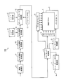
- FIG. 1 is a block diagram showing a schematic configuration of a liquid crystal display device for stereoscopic display according to a first embodiment of the present invention.
- FIG. 2 is a timing chart showing the driving operation of the liquid crystal display device.
- FIG. 3 is a waveform diagram showing the gradation value of the image data written to a certain pixel at the vertical position indicated by the line AB in FIG.
- FIG. 4 is a diagram illustrating an example of a lookup table for the first subframe and the third subframe.
- FIG. 5 is a diagram illustrating an example of a lookup table for the second subframe and the fourth subframe.
- FIG. 1 is a block diagram showing a schematic configuration of a liquid crystal display device for stereoscopic display according to a first embodiment of the present invention.
- FIG. 2 is a timing chart showing the driving operation of the liquid crystal display device.
- FIG. 3 is a waveform diagram showing the gradation value of the image data written to a certain pixel at the vertical position indicated by the
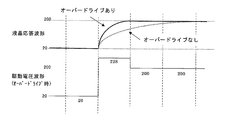
- FIG. 6 is a waveform diagram showing the difference in the response of the liquid crystal when the overdrive process is performed and when the display is switched from the 20th gradation to the 200th gradation.
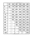
- FIG. 7 shows an example of a lookup table stored in the LUT holding unit referred to by the overdrive processing unit.
- FIG. 8 is a block diagram showing a schematic configuration of a liquid crystal display device according to Embodiment 2 of the present invention.
- a liquid crystal display device for stereoscopic display includes a liquid crystal panel having a plurality of pixels, a backlight disposed behind the liquid crystal panel to illuminate the liquid crystal panel, and the liquid crystal panel.
- a display control unit that alternately displays a right-eye image and a left-eye image every two subframes, and a pixel having a gradation difference equal to or greater than a predetermined threshold is extracted from the right-eye image and the left-eye image In the two sub-frames for displaying the image with the higher gray level of the image for the right eye and the image for the left eye for the pixel extracted by the image comparison unit and the pixel extracted by the image comparison unit.
- an image conversion unit that converts the gradation of the pixel in the subframe to a value higher than the original gradation and converts the gradation of the pixel in the subsequent subframe to a value lower than the original gradation.
- the pixel in the preceding sub-frame includes: Image data with a gradation higher than the original gradation is written, and image data with a gradation lower than the original gradation is written into the pixel in the subsequent subframe.
- overdrive processing refers to data corresponding to gradations that are higher (or lower) than target gradations in pixel data (that is, voltages applied to the pixels) to be written into the pixels in consideration of response delay of the liquid crystal. It is a process to correct the value.
- the overdrive processing unit by providing the overdrive processing unit, it is possible to compensate for a delay in the response of the liquid crystal and to more reliably suppress the occurrence of crosstalk.
- the image conversion unit displays, for the pixel extracted by the image comparison unit, an image having a lower gradation of the pixel of the right-eye image and the left-eye image.
- the gradation of the pixel may be maintained at the original gradation (third structure).
- the first to third configurations further include a backlight control unit that controls turning on and off of the backlight, and the backlight control unit turns off the backlight in one of the two subframes. It is preferable to adopt a configuration (fourth configuration).
- the effect of inserting a black frame between the right-eye image and the left-eye image is obtained by turning off the backlight every other subframe.
- the first to third configurations further include a backlight control unit that controls lighting and extinguishing of the backlight, and the backlight control unit controls the writing order of the image data in the pixel region of the liquid crystal panel. It is also preferable to control the backlight so that a plurality of sub-areas constituting the pixel area of the liquid crystal panel are sequentially illuminated in a time-sharing manner (fifth structure).
- the fifth configuration by synchronizing the illumination by the backlight and the writing of the image data, it is possible to compensate for the delay in the response speed of the liquid crystal and to illuminate only the portion where the response of the liquid crystal is completed. . Thereby, crosstalk can be more reliably suppressed.
- the original gradation of the left-eye image and the right-eye image, the converted gradation for the preceding subframe, and the converted gradation for the subsequent subframe It is also possible to further comprise a table storage unit that stores a table defining the gradations of the image, and the image conversion unit refers to the table to determine the converted gradations (sixth configuration).
- a driving method includes a liquid crystal panel having a plurality of pixels, and a backlight disposed behind the liquid crystal panel to illuminate the liquid crystal panel.
- This is a driving method of a liquid crystal display device for stereoscopic display in which an image for an eye and an image for a left eye are alternately displayed every two sub frames.
- This driving method includes a step of extracting pixels having a gradation difference equal to or greater than a predetermined threshold in the right-eye image and the left-eye image, and for the extracted pixels, the right-eye image and the left-eye image are extracted.
- the gradation of the pixel in the preceding sub-frame is converted to a value higher than the original gradation, and in the subsequent sub-frame Converting the gradation of the pixel to a value lower than the original gradation.
- FIG. 1 is a block diagram showing a schematic configuration of a stereoscopic display liquid crystal display device 100 (hereinafter simply referred to as a liquid crystal display device 100) according to a first embodiment of the present invention.
- the liquid crystal display device 100 includes a liquid crystal panel 1, a backlight 2, a backlight driving unit 3, a gate driver 4, a data driver 5, a timing control unit 6, a shutter glasses driving unit 7, and an image processing unit 8.
- a left-right image comparison unit 9 a left-right image storage unit 10, a left-right image conversion unit 11, an overdrive processing unit 12, a frame memory 13, and LUT (look-up table) holding units 14 and 15.
- the liquid crystal panel 1 mainly includes an active matrix substrate, a counter substrate, and a liquid crystal layer sealed between these substrates.
- the type of liquid crystal and the driving mode of the liquid crystal panel 1 are arbitrary and are not particularly limited.
- the gate driver 4 is connected to a plurality of gate lines provided on the active matrix substrate of the liquid crystal panel 1.
- the data driver 5 is connected to a plurality of source lines provided on the active matrix substrate of the liquid crystal panel 1.
- the gate driver 4 sequentially supplies selection signals to the plurality of gate lines in accordance with the synchronization signal supplied from the timing control unit 6.
- the data driver 5 supplies a data signal corresponding to an image to be displayed to the plurality of source lines in accordance with the synchronization signal supplied from the timing control unit 6. Thereby, in the liquid crystal panel 1, pixels connected to the gate line to which the selection signal is supplied from the gate driver 4 perform display according to the gradation of the data signal supplied from the data driver 5.
- the backlight 2 is a surface light source that illuminates the liquid crystal panel 1 from the back.
- the configuration of the backlight 2 is not particularly limited, and may be either a sidelight type or a direct type.
- the backlight 2 is controlled to be turned on and off by the backlight driving unit 3.
- the backlight 2 is configured to divide the pixel region of the liquid crystal panel 1 into a plurality of sub-regions in the vertical direction and to sequentially illuminate these sub-regions in a time-division manner.
- the backlight 2 is provided with a plurality of light sources corresponding to the plurality of sub-regions, respectively.
- the backlight drive unit 3 turns on only a part of the plurality of light sources according to the synchronization signal supplied from the timing control unit 6, thereby focusing on the sub-region near the gate line to which the selection signal is supplied. Illuminate. Details of lighting control of the backlight 2 by the backlight driving unit 3 will be described later.
- the timing control unit 6 outputs a synchronization signal for controlling the operation timing to the gate driver 4 and the data driver 5 and also to the backlight driving unit 3 and the shutter glasses driving unit 7. To do.
- the shutter glasses driving unit 7 switches the left eye lens and the right eye lens of the shutter glasses (not shown) according to the synchronization signal supplied from the timing control unit 6. That is, each of the left eye lens and the right eye lens of the shutter glasses is provided with, for example, a liquid crystal shutter or the like, and the left eye lens and the right eye lens are alternately transmissive. Therefore, the left eye lens of the shutter glasses is in a transmissive state while the left eye image is displayed on the liquid crystal panel 1, and the right eye lens is in a transmissive state while the right eye image is displayed.
- the timing control unit 6 controls the operation timing of the gate driver 4, the data driver 5, and the shutter glasses driving unit 7.
- the image processing unit 8 receives data of an image to be displayed on the liquid crystal display device 100 from the outside, and generates right-eye image data and left-eye image data in consideration of parallax. Note that the image processing unit 8 may directly receive the right-eye image data and the left-eye image data from the outside. In this case, the image processing unit 8 does not need to generate right-eye image data and left-eye image data from the input image data.
- the left-right image comparison unit 9 receives the right-eye image data and the left-eye image data from the image processing unit 8, and detects pixels having a gradation difference equal to or greater than a predetermined threshold in the left and right images.
- a predetermined threshold can be determined as appropriate, in the present embodiment, the image data is assumed to have 256 gradations, and a pixel having a gradation difference of 128 gradations or more is selected as the left and right image comparison unit 9. Shall be detected.
- the left and right image storage unit 10 is a memory that stores information on pixels that are determined by the left and right image comparison unit 9 to have a gradation difference equal to or greater than a predetermined threshold. Although this information storage method is arbitrary, in this embodiment, the flag information of the pixel determined to have a gradation difference is set to “ON” and stored in the left and right image storage unit 10.
- the LUT holding units 14 and 15 are memories in which lookup tables are stored in advance.
- the LUT holding unit 14 stores a lookup table referred to by the left and right image conversion unit 11.
- the LUT holding unit 15 stores a lookup table referred to by the overdrive processing unit 12. These lookup tables are stored in the LUT holding units 14 and 15 when the liquid crystal display device 100 is manufactured.
- the lookup table data may be modified when the liquid crystal display device 100 is operated.
- the left and right image conversion unit 11 refers to the look-up table of the LUT holding unit 14 for the pixel whose flag information is “ON”, and adjusts the gradation value of the image data written to the pixel.
- the adjustment of the gradation value of the image data will be described in detail later.
- the overdrive processing unit 12 refers to the lookup table in the LUT holding unit 15 and performs overdrive processing on the image data of the subframe. This overdrive process will also be described in detail later.
- the frame memory 13 is used as a work memory in overdrive processing or the like, and temporarily stores gradation data of each pixel in the previous frame.
- FIG. 2 is a timing chart showing the driving operation of the liquid crystal display device 100.
- the liquid crystal display device 100 displays an original image of 60 Hz (about 16.7 milliseconds) in one frame by four subframes of 240 Hz (about 4.2 milliseconds). That is, in this embodiment, a right-eye image and a left-eye image are generated from an original image, a right-eye image is displayed in the first two subframes, and a left-eye image is displayed in the second two subframes. indicate.
- the backlight 2 is turned off in the preceding subframe (referred to as “first subframe”) of the first two subframes displaying the right-eye image.
- the backlight 2 is turned on in the latter subframe (referred to as “second subframe”) of the first two subframes displaying the right-eye image.
- the backlight 2 is turned off in the preceding subframe (referred to as “third subframe”) among the latter two subframes displaying the left-eye image.
- the backlight 2 is turned on in the latter subframe (referred to as “fourth subframe”) of the latter two subframes displaying the left-eye image.
- the backlight 2 is configured to divide the pixel region of the liquid crystal panel 1 into eight sub-regions in the vertical direction and to illuminate these sub-regions in a time division manner. That is, in the example of FIG. 2, in the pixel region of the liquid crystal panel 1, a plurality of gate lines are sequentially selected from the top row in the vertical direction, and pixel data is written (scanned) to each. .
- the backlight 2 illuminates the eight sub-regions of the pixel region of the liquid crystal panel 1 in order from the uppermost sub-region in synchronization with the writing (scanning) of the pixel data. Note that the illumination periods of adjacent sub-regions overlap.
- the right eye lens is in a transmissive state in a period corresponding to approximately two subframe periods from the middle of the first subframe to the middle of the third subframe.
- the left eye lens of the shutter glasses is in a transmissive state in a period corresponding to approximately two subframe periods from the middle of the third subframe to the middle of the first subframe in the next frame.
- the right-eye lens of the shutter glasses is in a transmissive state
- the left-eye image is displayed
- the backlight 2 is lit
- the left-eye lens of the shutter glasses is in a transmissive state, whereby the right-eye image and the left-eye image are alternately recognized by the observer, and stereoscopic display can be realized.
- the backlight 2 is turned off in the first subframe and the third subframe. Thereby, it is as if a black screen is inserted between the right-eye image and the left-eye image, and there is an advantage that the moving image display performance is improved.
- FIG. 3 is a waveform diagram showing the gradation value of the image data written to a certain pixel at the vertical position indicated by the line AB in FIG.
- time t0 is the time at which writing of the right-eye image data is started in the first subframe with respect to the pixel at the vertical position indicated by line AB.
- Time t1 is a time one subframe period after time t0, and is a time when writing of right-eye image data to the pixel is started in the second subframe.
- Time t2 is a time at which writing of the left-eye image data to the pixel is started in the third subframe.
- Time t3 is a time at which writing of the left-eye image data to the pixel is started in the fourth subframe.
- time t5 is a time when the backlight 2 starts to be turned on in the vertical sub-region indicated by the line AB in the second subframe
- time t6 is the backlight 2 turned off. It is time to be.
- Time t7 is the time when the backlight 2 starts to be turned on in the sub-region at the vertical position indicated by line AB in the fourth subframe
- time t8 is the time when the backlight 2 is turned off.
- a broken line L1 is a target gradation (that is, an original gradation of image data), and a solid line L2 is a corrected gradation written to a pixel.
- pixels that have a gradation difference equal to or greater than a predetermined threshold between the right-eye image and the left-eye image that is, pixels whose flag information is “ON”.
- the gradation of the pixel is corrected to a higher value, and in the subsequent subframe, the pixel Is adjusted to a lower value.
- Such correction of the gradation value is performed by the left and right image conversion unit 11 referring to the lookup table of the LUT holding unit 14.
- FIGS. 4 and 5 are diagrams showing a specific example of the lookup table stored in the LUT holding unit 14.
- FIG. 4 is an example of a lookup table for the first subframe and the third subframe
- FIG. 5 is an example of a lookup table for the second subframe and the fourth subframe. Note that the gradation values shown in FIGS. 4 and 5 are merely examples, and the gradation values stored in the lookup table upon implementation are not limited to the specific examples shown here.
- the left and right image conversion unit 11 refers to the lookup table illustrated in FIG. 4 and acquires values corresponding to “240” and “16”. In this case, the acquired value is 255. Therefore, the left-right image conversion unit 11 corrects the gradation of the pixel in the first sub-frame displaying the right-eye image from “240” to “255”.
- the left-right image conversion unit 11 refers to the lookup table illustrated in FIG. 5 and acquires “18” as a value corresponding to “240” and “16”.
- the left-right image conversion unit 11 corrects the gradation of the pixel in the second subframe displaying the right-eye image from “240” to “18”.
- the left-right image conversion unit 11 corrects the gradation of pixels whose flag information is not “ON”, that is, pixels where there is no significant difference in gradation between the right-eye image and the left-eye image. Instead, the input gradation is passed to the overdrive processing unit 12 as it is.
- the gradation in the preceding subframe is set to a value higher than the original gradation in the higher gradation image, and By setting the gradation in the subframe to a value lower than the original gradation, the following effects can be obtained.
- crosstalk occurs in a portion where the luminance difference is large between the right-eye image and the left-eye image. Further, due to human visual characteristics, when one of the right-eye image and the left-eye image has a portion with a lower gradation than the same portion of the other image, the other portion has a lower gradation. The image of the image is easy to see.
- the numerical value in the lookup table is adjusted so that the integrated luminance of the overshoot portion when the luminance increases is the same as the target luminance. That is, it is preferable to determine the numerical value of the lookup table so that the area of the region a1 and the area of the region a2 shown in FIG.
- the corrected gradation is sent from the left / right image conversion unit 11 to the overdrive processing unit 12.
- the overdrive processing unit 12 performs overdrive processing by referring to the lookup table of the LUT holding unit 15.
- overdrive processing refers to data corresponding to gradations that are higher (or lower) than target gradations in pixel data (that is, voltages applied to the pixels) to be written into the pixels in consideration of response delay of the liquid crystal. It is a process to correct the value. For example, when a gradation higher than the currently displayed gradation is displayed next, the value of data written to the pixel is converted to a value corresponding to a gradation higher than the target gradation. When a gradation lower than the currently displayed gradation is displayed next, the value of data written to the pixel is converted to a value corresponding to a gradation lower than the target gradation.
- FIG. 6 is a waveform diagram showing the difference in response of the liquid crystal when the overdrive process is performed and when the display is switched from 20 gradations to 200 gradations.
- the upper solid line represents the transition of gradation when the overdrive process is performed
- the lower stage represents the drive voltage waveform supplied during the overdrive process.
- the upper broken line represents the transition of gradation when overdrive processing is not performed for comparison.
- FIG. 7 shows an example of a lookup table stored in the LUT holding unit 15 referred to by the overdrive processing unit 12.
- the gradation value defined in this table is used at the time of transition from the current gradation shown on the vertical axis to the target gradation shown on the horizontal axis.
- the table value is set so that the display gradation does not exceed the target gradation.
- the lighting start time of the backlight 2 is uniformly defined.
- the lighting start time of the backlight 2 may be changed according to the image displayed on the liquid crystal panel 1. good. This is because the response speed of the liquid crystal varies depending on how the gradation changes.
- FIG. 8 is a block diagram showing a schematic configuration of the liquid crystal display device 200 according to the second embodiment.
- the liquid crystal display device 200 of the present embodiment omits the left-right image conversion unit 11 compared to the liquid crystal display device 100 of the first embodiment.
- the overdrive processing unit 12 refers to the LUT holding units 14 and 15 and performs the gradation value correction processing that is performed by the left and right image conversion unit 11 in the first embodiment. Note that the gradation value correction process itself is the same as that in the first embodiment, and thus a redundant description will not be given.
- the backlight 2 divides the pixel area of the liquid crystal panel 1 into a plurality of sub-areas and sequentially illuminates these sub-areas in a time-division manner is exemplified.
- the backlight may be configured to illuminate the entire pixel region when it is lit.
- the configuration for converting the gradation value by referring to the lookup table is exemplified.
- the determination of the gradation value is not limited to the method of referring to the lookup table, and for example, a configuration obtained by calculation may be used.
- the present invention can be industrially used as a liquid crystal display device for stereoscopic display that allows an observer to visually recognize a stereoscopic image.
Landscapes
- Engineering & Computer Science (AREA)
- Physics & Mathematics (AREA)
- Computer Hardware Design (AREA)
- General Physics & Mathematics (AREA)
- Theoretical Computer Science (AREA)
- Chemical & Material Sciences (AREA)
- Crystallography & Structural Chemistry (AREA)
- Control Of Indicators Other Than Cathode Ray Tubes (AREA)
- Liquid Crystal (AREA)
Abstract
クロストーク現象を抑制することにより、輪郭が鮮明な立体画像を観察者に視認させることができる立体表示用液晶表示装置を提供する。立体表示用液晶表示装置(100)は、液晶パネル(1)に、右眼用画像と左眼用画像とを2サブフレームずつ交互に表示させる。この液晶表示装置は、右眼用画像と左眼用画像とにおいて、所定の閾値以上の階調差がある画素を抽出する画像比較部(9)と、画像比較部(9)で抽出された画素について、前記右眼用画像と左眼用画像とのうち当該画素の階調が高い方の画像を表示する前記2つのサブフレームにおいて、先行するサブフレームにおける当該画素の階調を原階調よりも高い値に変換し、後のサブフレームにおける当該画素の階調を原階調よりも低い値に変換する画像変換部(11)とを備える。
Description
本発明は、立体表示用液晶表示装置に関し、特に、いわゆるフレームシーケンシャル方式で立体表示を実現する液晶表示装置に関する。
従来から、特殊なメガネを用いて、観察者に立体画像を見せる立体表示装置が知られている。例えば、特開2010-117437号公報には、右眼用画像と左眼用画像とを交互に表示する液晶表示装置の画像切換周期と同期して、光シャッターメガネの光透過状態を制御することにより、視聴者に立体画像を視認させる液晶表示装置が記載されている。このように、右眼用画像と左眼用画像とを時分割で交互に表示する方式は、一般的に、フレームシーケンシャル方式と呼ばれている。
上述したようなフレームシーケンシャル方式の立体表示用液晶表示装置においては、一方の眼用の画像に他方の眼用の画像が混入する、いわゆるクロストーク現象が生じることがある。クロストーク現象が起きると、観察者に視認される画像は、輪郭が二重または三重にぼやけた画像となる。
クロストーク現象の主な原因の一つとして、液晶の応答速度が十分ではないことがあげられる。例えば、右眼用画像を表示した後に、左眼用画像に表示を切り替えるべく駆動電圧を印加した場合、その駆動電圧の変化に対して液晶分子が十分高速に応答することができないと、左眼用画像に右眼用画像が混入してしまう。この現象は、左眼用画像と右眼用画像とにおいて表示内容に差がある画素部分にのみ起こる。したがって、画像のエッジ(輪郭)部分が二重または三重に見えるという問題が生じる。
そこで、上記の問題を鑑み、以下の開示においては、クロストーク現象を抑制することにより、輪郭が鮮明な立体画像を観察者に視認させることができる立体表示用液晶表示装置を提供することを目的とする。
上記の目的を達成するため、ここに開示する立体表示用液晶表示装置は、
複数の画素を有する液晶パネルと、
該液晶パネルの後方に配置されて、該液晶パネルを照明するバックライトと、
前記液晶パネルに、右眼用画像と左眼用画像とを2サブフレームずつ交互に表示させる表示制御部と、
前記右眼用画像と左眼用画像とにおいて、所定の閾値以上の階調差がある画素を抽出する画像比較部と、
前記画像比較部で抽出された画素について、前記右眼用画像と左眼用画像とのうち当該画素の階調が高い方の画像を表示する前記2サブフレームにおいて、先行するサブフレームにおける当該画素の階調を原階調よりも高い値に変換し、後のサブフレームにおける当該画素の階調を原階調よりも低い値に変換する画像変換部とを備えた構成である。
複数の画素を有する液晶パネルと、
該液晶パネルの後方に配置されて、該液晶パネルを照明するバックライトと、
前記液晶パネルに、右眼用画像と左眼用画像とを2サブフレームずつ交互に表示させる表示制御部と、
前記右眼用画像と左眼用画像とにおいて、所定の閾値以上の階調差がある画素を抽出する画像比較部と、
前記画像比較部で抽出された画素について、前記右眼用画像と左眼用画像とのうち当該画素の階調が高い方の画像を表示する前記2サブフレームにおいて、先行するサブフレームにおける当該画素の階調を原階調よりも高い値に変換し、後のサブフレームにおける当該画素の階調を原階調よりも低い値に変換する画像変換部とを備えた構成である。
上記の構成によれば、クロストーク現象を抑制することにより、輪郭が鮮明な立体画像を観察者に視認させることができる立体表示用液晶表示装置を提供できる。
本発明の一実施形態にかかる立体表示用液晶表示装置は、複数の画素を有する液晶パネルと、該液晶パネルの後方に配置されて、該液晶パネルを照明するバックライトと、前記液晶パネルに、右眼用画像と左眼用画像とを2サブフレームずつ交互に表示させる表示制御部と、前記右眼用画像と左眼用画像とにおいて、所定の閾値以上の階調差がある画素を抽出する画像比較部と、前記画像比較部で抽出された画素について、前記右眼用画像と左眼用画像とのうち当該画素の階調が高い方の画像を表示する前記2サブフレームにおいて、先行するサブフレームにおける当該画素の階調を原階調よりも高い値に変換し、後のサブフレームにおける当該画素の階調を原階調よりも低い値に変換する画像変換部とを備えた構成である(第1の構成)。
この第1の構成によれば、右眼用画像と左眼用画像とのうち当該画素の階調が高い方の画像を表示する前記2サブフレームにおいて、先行するサブフレームにおける当該画素には、原階調よりも高い階調の画像データが書き込まれ、後のサブフレームにおける当該画素には、原階調よりも低い階調の画像データが書き込まれる。
これにより、高階調の輝度を保ちつつ、高階調から低階調への表示の切り替わりにおける液晶の応答を早くする効果がある。この結果、クロストークの発生を抑制でき、鮮明な輪郭を持つ立体画像を観察者に視認させることが可能な、立体表示用液晶表示装置を提供できる。
前記第1の構成において、前記画素変換部の後段に、オーバードライブ処理部をさらに備えた構成とすることが好ましい(第2の構成)。なお、オーバードライブ処理とは、液晶の応答遅れを考慮して、画素に書き込む画素データ(すなわち画素に印加する電圧)を、目標とする階調よりも高い(または低い)階調に相当するデータ値に修正する処理のことである。
この第2の構成によれば、オーバードライブ処理部を備えたことにより、液晶の応答の遅れを補償し、クロストークの発生をより確実に抑制することができる。
前記第1の構成において、前記画像変換部が、前記画像比較部で抽出された画素について、前記右眼用画像と左眼用画像とのうち当該画素の階調が低い方の画像を表示する前記2サブフレームにおいては、当該画素の階調を原階調に維持する構成としても良い(第3の構成)。
また、前記第1~第3の構成において、前記バックライトの点灯および消灯を制御するバックライト制御部をさらに備え、前記2サブフレームの一方において、前記バックライト制御部が前記バックライトを消灯する構成とすることが好ましい(第4の構成)。
この第4の構成によれば、1サブフレームおきにバックライトを消灯することにより、右眼用画像と左眼用画像との間に黒フレームを挿入したような効果が得られる。これにより、特に動画の表示性能が向上するという利点がある。
また、前記第1~第3の構成において、前記バックライトの点灯および消灯を制御するバックライト制御部をさらに備え、前記バックライト制御部が、前記液晶パネルの画素領域における画像データの書き込み順序に同期して、前記液晶パネルの画素領域を構成する複数のサブ領域を時分割で順次照明するよう、前記バックライトを制御する構成とすることも好ましい(第5の構成)。
この第5の構成によれば、バックライトによる照明と画像データの書き込みとの同期をとることにより、液晶の応答速度の遅れを補償し、液晶の応答が完了した部分のみを照明することができる。これにより、クロストークをより確実に抑制できる。
また、前記第1~第5の構成において、左眼用画像および右眼用画像の原階調と、前記先行するサブフレームについての変換後の階調と、前記後のサブフレームについての変換後の階調とを規定したテーブルを格納するテーブル記憶部をさらに備え、前記画像変換部が、前記テーブルを参照して変換後の階調を決定する構成としても良い(第6の構成)。
また、本発明の他の側面にかかる駆動方法は、複数の画素を有する液晶パネルと、該液晶パネルの後方に配置されて該液晶パネルを照明するバックライトとを備え、前記液晶パネルに、右眼用画像と左眼用画像とを2サブフレームずつ交互に表示させる立体表示用液晶表示装置の駆動方法である。この駆動方法は、前記右眼用画像と左眼用画像とにおいて、所定の閾値以上の階調差がある画素を抽出する工程と、抽出された画素について、前記右眼用画像と左眼用画像とのうち当該画素の階調が高い方の画像を表示する前記2サブフレームにおいて、先行するサブフレームにおける当該画素の階調を原階調よりも高い値に変換し、後のサブフレームにおける当該画素の階調を原階調よりも低い値に変換する工程とを含む。
[実施の形態]
以下、本発明のより具体的な実施形態について、図面を参照しながら説明する。なお、以下で参照する各図は、説明の便宜上、本発明の実施形態の構成部材のうち、本発明を説明するために必要な主要部材のみを簡略化して示したものである。従って、本発明に係る立体表示装置は、本明細書が参照する各図に示されていない任意の構成部材を備え得る。また、各図中の部材の寸法は、実際の構成部材の寸法および各部材の寸法比率等を忠実に表したものではない。
以下、本発明のより具体的な実施形態について、図面を参照しながら説明する。なお、以下で参照する各図は、説明の便宜上、本発明の実施形態の構成部材のうち、本発明を説明するために必要な主要部材のみを簡略化して示したものである。従って、本発明に係る立体表示装置は、本明細書が参照する各図に示されていない任意の構成部材を備え得る。また、各図中の部材の寸法は、実際の構成部材の寸法および各部材の寸法比率等を忠実に表したものではない。
[第1の実施形態]
図1は、本発明の第一の実施形態にかかる立体表示用液晶表示装置100(以下、単に液晶表示装置100と称する。)の概略構成を示すブロック図である。図1に示すように、液晶表示装置100は、液晶パネル1、バックライト2、バックライト駆動部3、ゲートドライバ4、データドライバ5、タイミング制御部6、シャッターメガネ駆動部7、画像処理部8、左右画像比較部9、左右画像記憶部10、左右画像変換部11、オーバードライブ処理部12、フレームメモリ13、および、LUT(ルックアップテーブル)保持部14,15を備えている。
図1は、本発明の第一の実施形態にかかる立体表示用液晶表示装置100(以下、単に液晶表示装置100と称する。)の概略構成を示すブロック図である。図1に示すように、液晶表示装置100は、液晶パネル1、バックライト2、バックライト駆動部3、ゲートドライバ4、データドライバ5、タイミング制御部6、シャッターメガネ駆動部7、画像処理部8、左右画像比較部9、左右画像記憶部10、左右画像変換部11、オーバードライブ処理部12、フレームメモリ13、および、LUT(ルックアップテーブル)保持部14,15を備えている。
液晶パネル1は、図示はしないが、主として、アクティブマトリクス基板と、対向基板と、これらの基板の間に封入された液晶層とを備えている。液晶パネル1の液晶の種類や駆動モードは任意であり、特に限定されない。
ゲートドライバ4は、液晶パネル1のアクティブマトリクス基板に設けられた複数のゲート線へ接続されている。データドライバ5は、液晶パネル1のアクティブマトリクス基板に設けられた複数のソース線へ接続されている。ゲートドライバ4は、タイミング制御部6から供給される同期信号にしたがい、前記複数のゲート線へ、順次、選択信号を供給する。データドライバ5は、タイミング制御部6から供給される同期信号にしたがい、前記複数のソース線へ、表示すべき画像に応じたデータ信号を供給する。これにより、液晶パネル1においては、ゲートドライバ4から選択信号が供給されているゲート線に接続された画素が、データドライバ5から供給されたデータ信号の階調に応じた表示を行う。
バックライト2は、液晶パネル1を背面から照明する面光源である。バックライト2の構成も特に限定されず、サイドライト型および直下型のいずれの形式であっても良い。バックライト2の光源としては、例えば、冷陰極管や発光ダイオード(LED)等を採用することができる。バックライト2は、バックライト駆動部3によって点灯および消灯が制御される。
なお、バックライト2は、液晶パネル1の画素領域を垂直方向に複数のサブ領域に分割し、これらのサブ領域を時分割で順次照明するように構成されている。バックライト2には、前記複数のサブ領域にそれぞれ対応して複数の光源が設けられている。バックライト駆動部3が、タイミング制御部6から供給される同期信号にしたがって、前記複数の光源の一部のみを点灯させることにより、選択信号が供給されているゲート線近傍のサブ領域を中心に照明する。バックライト駆動部3によるバックライト2の点灯制御の詳細については、後に説明する。
タイミング制御部6は、前述のとおり、ゲートドライバ4およびデータドライバ5に対して、また、バックライト駆動部3およびシャッターメガネ駆動部7に対しても、動作タイミングを制御するための同期信号を出力する。
シャッターメガネ駆動部7は、タイミング制御部6から供給される同期信号にしたがい、シャッターメガネ(図示せず)の左眼レンズおよび右眼レンズの切替を行う。すなわち、シャッターメガネの左眼レンズおよび右眼レンズのそれぞれには、例えば液晶シャッタ等が設けられており、左眼レンズおよび右眼レンズが交互に透過状態となる。したがって、液晶パネル1において左眼用画像を表示している間はシャッターメガネの左眼レンズを透過状態とし、右眼用画像を表示している間は右眼レンズを透過状態とするように、タイミング制御部6が、ゲートドライバ4、データドライバ5、および、シャッターメガネ駆動部7の動作タイミングを制御する。
画像処理部8は、液晶表示装置100で表示すべき画像のデータを外部から受け取り、視差を考慮した右眼用画像データと左眼用画像データとを生成する。なお、画像処理部8が、右眼用画像データおよび左眼用画像データを外部から直接受け取る構成であっても良い。この場合、画像処理部8は、入力された画像データから右眼用画像データおよび左眼用画像データを生成する必要はない。
左右画像比較部9は、画像処理部8から右眼用画像データと左眼用画像データとを受け取り、左右の画像において階調差が所定の閾値以上である画素を検出する。なお、前記所定の閾値は適宜に決定することができるが、本実施形態においては、画像データが256階調であるものとし、128階調以上の階調差がある画素を左右画像比較部9が検出するものとする。
左右画像記憶部10は、左右画像比較部9において所定の閾値以上の階調差があると判断された画素の情報が記憶されるメモリである。この情報の記憶方法は任意であるが、本実施形態では、階調差があると判断された画素のフラグ情報を「オン」として、左右画像記憶部10に記憶する。
LUT保持部14,15は、ルックアップテーブルがあらかじめ格納されたメモリである。LUT保持部14は、左右画像変換部11が参照するルックアップテーブルを格納している。LUT保持部15は、オーバードライブ処理部12が参照するルックアップテーブルを格納している。これらのルックアップテーブルは、液晶表示装置100の製造時に、LUT保持部14,15に格納される。なお、ルックアップテーブルのデータを、液晶表示装置100の動作時等に修正可能な構成としても良い。
左右画像変換部11は、フラグ情報が「オン」である画素について、LUT保持部14のルックアップテーブルを参照し、当該画素に書き込まれる画像データの階調値を調整する。この画像データの階調値の調整については、後に詳しく説明する。
オーバードライブ処理部12は、LUT保持部15のルックアップテーブルを参照し、サブフレームの画像データに対してオーバードライブ処理を行う。このオーバードライブ処理についても、後に詳しく説明する。
フレームメモリ13は、オーバードライブ処理等におけるワークメモリとして用いられ、前フレームの各画素の階調データ等を一時的に記憶する。
次に、上記の構成にかかる液晶表示装置100の動作について、説明する。図2は、液晶表示装置100の駆動動作を示すタイミングチャートである。図2に示すように、液晶表示装置100は、1フレーム60Hz(約16.7ミリ秒)の原画像を、240Hz(約4.2ミリ秒)の4つのサブフレームによって表示する。すなわち、本実施形態においては、原画像から右眼用画像と左眼用画像とを生成し、前半2つのサブフレームで右眼用画像を表示し、後半2つのサブフレームで左眼用画像を表示する。
右眼用画像を表示する前半2つのサブフレームのうち先行するサブフレーム(「第1サブフレーム」と称する。)においては、バックライト2は消灯されている。右眼用画像を表示する前半2つのサブフレームのうち後のサブフレーム(「第2サブフレーム」と称する。)において、バックライト2は点灯される。同様に、左眼用画像を表示する後半2つのサブフレームのうち先行するサブフレーム(「第3サブフレーム」と称する。)においては、バックライト2は消灯されている。左眼用画像を表示する後半2つのサブフレームのうち後のサブフレーム(「第4サブフレーム」と称する。)において、バックライト2は点灯される。
なお、図2に示した例では、バックライト2は、液晶パネル1の画素領域を垂直方向に8つのサブ領域に分割し、これらのサブ領域を時分割で照明するよう構成されている。すなわち、図2の例では、液晶パネル1の画素領域において、垂直方向において最も上にある行から順に、複数のゲート線が順次選択され、それぞれに対して画素データの書き込み(走査)が行われる。バックライト2は、画素データの書き込み(走査)に同期して、液晶パネル1の画素領域の8つのサブ領域を、最も上にあるサブ領域から順に照明する。なお、隣接するサブ領域同士の照明期間は重複している。
また、図2に示すように、シャッターメガネは、第1サブフレームの途中から第3サブフレームの途中までの、およそ2つのサブフレーム期間に相当する期間において、右眼レンズが透過状態となる。また、シャッターメガネの左眼レンズは、第3サブフレームの途中から次のフレームにおける第1サブフレームの途中までの、およそ2つのサブフレーム期間に相当する期間において、透過状態となる。すなわち、右眼用画像が表示され、かつバックライト2が点灯される第2サブフレームにおいて、シャッターメガネの右眼レンズが透過状態とされ、左眼用画像が表示され、かつバックライト2が点灯される第4サブフレームにおいて、シャッターメガネの左眼レンズが透過状態とされることにより、右眼用画像と左眼用画像とを観察者に交互に認識させ、立体表示を実現することができる。
なお、液晶表示装置100においては、第1サブフレームおよび第3サブフレームにおいてバックライト2が消灯される。これにより、あたかも右眼用画像と左眼用画像との間に黒画面を挿入したかのようになり、動画表示性能が向上するという利点もある。
図3は、図2においてA-B線で示した垂直位置における、ある画素に書き込まれる画像データの階調値を示した波形図である。図3において、時刻t0は、A-B線で示す垂直位置にある画素に対して、第1サブフレームにおいて右眼用画像データの書き込みが開始される時刻である。時刻t1は、時刻t0から1サブフレーム期間後の時刻であり、第2サブフレームにおいて当該画素へ右眼用画像データの書き込みが開始される時刻である。時刻t2は、第3サブフレームにおいて当該画素へ左眼用画像データの書き込みが開始される時刻である。時刻t3は、第4サブフレームにおいて当該画素へ左目用画像データの書き込みが開始される時刻である。
また、図3において、時刻t5は、第2サブフレームにおいて、A-B線で示す垂直位置のサブ領域におけるバックライト2の点灯が開始される時刻であり、時刻t6は、バックライト2が消灯される時刻である。時刻t7は、第4サブフレームにおいて、A-B線で示す垂直位置のサブ領域におけるバックライト2の点灯が開始される時刻であり、時刻t8は、バックライト2が消灯される時刻である。
さらに、図3において、破線L1は、目標とする階調(すなわち画像データの本来の階調)であり、実線L2は、画素へ書き込まれる修正後の階調である。すなわち、本実施形態の液晶表示装置100においては、右眼用画像と左眼用画像とにおいて所定の閾値以上の階調差がある画素(すなわちフラグ情報が「オン」とされている画素)については、階調値が高い方の画像を表示する2つのサブフレームのうち先行するサブフレームにおいては、当該画素の階調をそれよりも高い値に修正し、後のサブフレームにおいては、当該画素の階調を、それよりも低い値に修正する。このような階調値の修正は、左右画像変換部11が、LUT保持部14のルックアップテーブルを参照することにより行う。
図4および図5は、LUT保持部14に格納されているルックアップテーブルの一具体例を示す図である。図4は、第1サブフレームおよび第3サブフレーム用のルックアップテーブルの例であり、図5は、第2サブフレームおよび第4サブフレーム用のルックアップテーブルの例である。なお、図4および図5に示した階調値はあくまでも一例であって、実施に際してルックアップテーブルへ格納する階調値は、ここに示した具体例のみに限定されない。
ここで、右眼用画像のある1つの画素の階調が240であり、左眼用画像における同じ位置の画素の階調が16である場合を想定する。この場合、左右画像変換部11が、図4に示したルックアップテーブルを参照し、「240」と「16」とに対応する値を取得する。この場合、取得される値は、255である。そこで、左右画像変換部11は、右眼用画像を表示する第1サブフレームにおける当該画素の階調を、「240」から「255」へ修正する。また、左右画像変換部11は、図5に示したルックアップテーブルを参照し、「240」と「16」とに対応する値として「18」を取得する。左右画像変換部11は、右眼用画像を表示する第2サブフレームにおける当該画素の階調を、「240」から「18」へ修正する。
なお、左右画像変換部11は、フラグ情報が「オン」となっていない画素、すなわち右眼用画像と左眼用画像とにおいて階調に大きな差がない画素については、階調の修正を行うことなく、入力階調をそのままオーバードライブ処理部12へ渡す。
このように、右眼用画像と左眼用画像とにおいて階調の差が大きい画素について、階調の高い方の画像において、先行するサブフレームにおける階調を原階調より高い値とし、後のサブフレームにおける階調を原階調より低い値とすることにより、以下のような効果がある。
すなわち、クロストークは、右眼用画像と左眼用画像とにおいて輝度差が大きい部分に生じる。また、人間の視覚特性から、右眼用画像および左眼用画像の一方において、他方の画像の同じ部分に比較して階調の低い部分が存在する場合、当該階調の低い部分に、他方の画像の像が見えやすい。
これに対して、本実施形態では、上述のように、先行するサブフレームにおける階調を原階調より高い値とし、後のサブフレームにおける階調を原階調より低い値とすることにより、高階調の輝度を保ちつつ、高階調から低階調への表示の切り替わりにおける液晶の応答を早くする効果がある。これにより、クロストークの発生を抑制できる。
なお、ルックアップテーブルの数値は、輝度上昇時におけるオーバーシュート部分の積分輝度が、目標輝度と同じになるように調整する。すなわち、図3に示す領域a1の面積と領域a2の面積とが等しくなるように、ルックアップテーブルの数値を決定することが好ましい。
修正後の階調は、左右画像変換部11からオーバードライブ処理部12へ送られる。ここで、オーバードライブ処理部12は、LUT保持部15のルックアップテーブルを参照することにより、オーバードライブ処理を行う。なお、オーバードライブ処理とは、液晶の応答遅れを考慮して、画素に書き込む画素データ(すなわち画素に印加する電圧)を、目標とする階調よりも高い(または低い)階調に相当するデータ値に修正する処理のことである。例えば、現在表示している階調よりも高い階調を次に表示する場合は、画素に書き込むデータの値を、目標とする階調よりもさらに高い階調に相当する値に変換する。また、現在表示している階調よりも低い階調を次に表示する場合は、画素に書き込むデータの値を、目標とする階調よりもさらに低い階調に相当する値に変換する。
ここで、オーバードライブ処理部12によって行われるオーバードライブ処理の一例について説明する。図6は、一例として、20階調から200階調へ表示を切り替える際に、オーバードライブ処理を行った場合と行わなかった場合の液晶の応答の違いを示す波形図である。図6において、上段の実線は、オーバードライブ処理を行った場合の階調の遷移を表し、下段は、オーバードライブ処理時に供給される駆動電圧波形を表す。上段の破線は、比較のために、オーバードライブ処理を行わなかった場合の階調の遷移を表す。
図6の下段に示すように、20階調から200階調へ表示を切り替える際に、オーバードライブ処理では、表示の切り替え時の最初のフレームにおいて、本来の目標階調である200階調よりも高い階調(図6の例では228階調)に相当する電圧を供給する。これにより、上段の実線に示すように、液晶はすみやかに応答し、表示される階調が目標の200階調へ早く到達する。一方、オーバードライブ処理を行わない場合は、表示される階調が目標の200階調へ到達するためには、少なからぬ時間(この例では3フレーム程度)を要する。
図7は、オーバードライブ処理部12が参照するLUT保持部15に格納されるルックアップテーブルの一例を示す。図7に示すルックアップテーブルにおいては、縦軸に示す現階調から、横軸に示す目標階調への遷移時に、このテーブルに規定されている階調値を用いる。図7に示すように、オーバードライブ処理においては、現階調よりも目標階調が大きい場合(図7に示すテーブルの右上側半分)は、目標階調よりも大きい階調値が用いられる。その逆に、現階調よりも目標階調が小さい場合(図7に示すテーブルの左下側半分)は、目標階調よりも小さい階調値が用いられる。なお、この際に、オーバードライブ処理においては、表示階調が目標階調を超えないように、テーブル値が設定される。
以上のように、本実施形態によれば、右眼用画像と左眼用画像とにおいて同一画素の階調に大きな差がある場合であっても、クロストークを抑制し、鮮明な輪郭の立体画像を観察者に視認させることができる。
なお、本実施形態では、バックライト2の点灯開始時点が一律に規定されているが、バックライト2の点灯開始時点を、液晶パネル1に表示される画像に応じて、変更するようにしても良い。液晶の応答速度は、階調がどのように変化するかによって異なるからである。
[第2の実施形態]
以下、本発明の第2の実施形態にかかる液晶表示装置について説明する。なお、以下の説明において、第1の実施形態において説明した構成については、第1の実施形態と同一の符号を付すことにより、それらの詳細な説明を省略する。
以下、本発明の第2の実施形態にかかる液晶表示装置について説明する。なお、以下の説明において、第1の実施形態において説明した構成については、第1の実施形態と同一の符号を付すことにより、それらの詳細な説明を省略する。
図8は、第2の実施形態にかかる液晶表示装置200の概略構成を示すブロック図である。図8に示すように、本実施形態の液晶表示装置200は、第1の実施形態の液晶表示装置100と比較して、左右画像変換部11が省略されている。液晶表示装置200では、オーバードライブ処理部12が、LUT保持部14,15を参照し、第1の実施形態において左右画像変換部11が行っていた階調値の修正処理を行う。なお、この階調値の修正処理自体については、第1の実施形態と同じであるため、重複した説明は行わない。
以上、本発明の実施形態について、詳述してきたが、これらはあくまでも例示であって、本発明は、上述の実施形態によって何ら限定されるものではない。
例えば、上記の実施形態においては、バックライト2が、液晶パネル1の画素領域を複数のサブ領域に分割し、これらのサブ領域を時分割で順次照明する構成を例示した。しかし、バックライトは、点灯時は画素領域全体を照明する構成としても良い。
あるいは、上記の実施形態においては、バックライト2が、1サブフレームおきに消灯される構成を開示した。しかし、バックライト2が常時点灯される構成であっても良い。
また、上記の実施形態においては、ルックアップテーブルを参照することによって、階調値を変換する構成を例示した。しかし、階調値の決定は、ルックアップテーブルを参照する方法のみに限定されず、例えば演算によって求める構成であっても良い。
本発明は、立体画像を観察者に視認させる立体表示用液晶表示装置として、産業上の利用が可能である。
Claims (7)
- 複数の画素を有する液晶パネルと、
該液晶パネルの後方に配置されて、該液晶パネルを照明するバックライトと、
前記液晶パネルに、右眼用画像と左眼用画像とを2サブフレームずつ交互に表示させる表示制御部と、
前記右眼用画像と左眼用画像とにおいて、所定の閾値以上の階調差がある画素を抽出する画像比較部と、
前記画像比較部で抽出された画素について、前記右眼用画像と左眼用画像とのうち当該画素の階調が高い方の画像を表示する前記2サブフレームにおいて、先行するサブフレームにおける当該画素の階調を原階調よりも高い値に変換し、後のサブフレームにおける当該画素の階調を原階調よりも低い値に変換する画像変換部とを備えた、立体表示用液晶表示装置。 - 前記画素変換部の後段に、オーバードライブ処理部をさらに備えた、請求項1に記載の立体表示用液晶表示装置。
- 前記画像変換部は、前記画像比較部で抽出された画素について、前記右眼用画像と左眼用画像とのうち当該画素の階調が低い方の画像を表示する前記2サブフレームにおいては、当該画素の階調を原階調に維持する、請求項1に記載の立体表示用液晶表示装置。
- 前記バックライトの点灯および消灯を制御するバックライト制御部をさらに備え、
前記2つのサブフレームの一方において、前記バックライト制御部が前記バックライトを消灯する、請求項1~3のいずれか一項に記載の立体表示用液晶表示装置。 - 前記バックライトの点灯および消灯を制御するバックライト制御部をさらに備え、
前記バックライト制御部が、前記液晶パネルの画素領域における画像データの書き込み順序に同期して、前記液晶パネルの画素領域を構成する複数のサブ領域を時分割で順次照明するよう、前記バックライトを制御する、請求項1~3のいずれか一項に記載の立体表示用液晶表示装置。 - 左眼用画像および右眼用画像の原階調と、前記先行するサブフレームについての変換後の階調と、前記後のサブフレームについての変換後の階調とを規定したテーブルを格納するテーブル記憶部をさらに備え、
前記画像変換部は、前記テーブルを参照して変換後の階調を決定する、請求項1~5のいずれか一項に記載の立体表示用液晶表示装置。 - 複数の画素を有する液晶パネルと、該液晶パネルの後方に配置されて該液晶パネルを照明するバックライトとを備え、前記液晶パネルに、右眼用画像と左眼用画像とを2サブフレームずつ交互に表示させる立体表示用液晶表示装置の駆動方法であって、
前記右眼用画像と左眼用画像とにおいて、所定の閾値以上の階調差がある画素を抽出し、
抽出された画素について、前記右眼用画像と左眼用画像とのうち当該画素の階調が高い方の画像を表示する前記2サブフレームにおいて、先行するサブフレームにおける当該画素の階調を原階調よりも高い値に変換し、後のサブフレームにおける当該画素の階調を原階調よりも低い値に変換する、立体表示用液晶表示装置の駆動方法。
Applications Claiming Priority (2)
| Application Number | Priority Date | Filing Date | Title |
|---|---|---|---|
| JP2010283394 | 2010-12-20 | ||
| JP2010-283394 | 2010-12-20 |
Publications (1)
| Publication Number | Publication Date |
|---|---|
| WO2012086495A1 true WO2012086495A1 (ja) | 2012-06-28 |
Family
ID=46313771
Family Applications (1)
| Application Number | Title | Priority Date | Filing Date |
|---|---|---|---|
| PCT/JP2011/078945 Ceased WO2012086495A1 (ja) | 2010-12-20 | 2011-12-14 | 立体表示用液晶表示装置 |
Country Status (1)
| Country | Link |
|---|---|
| WO (1) | WO2012086495A1 (ja) |
Citations (2)
| Publication number | Priority date | Publication date | Assignee | Title |
|---|---|---|---|---|
| JP2010091782A (ja) * | 2008-10-08 | 2010-04-22 | Mitsubishi Electric Corp | 液晶表示装置および立体画像表示装置 |
| JP2010282089A (ja) * | 2009-06-05 | 2010-12-16 | Sony Corp | 映像処理装置、表示装置および表示システム |
-
2011
- 2011-12-14 WO PCT/JP2011/078945 patent/WO2012086495A1/ja not_active Ceased
Patent Citations (2)
| Publication number | Priority date | Publication date | Assignee | Title |
|---|---|---|---|---|
| JP2010091782A (ja) * | 2008-10-08 | 2010-04-22 | Mitsubishi Electric Corp | 液晶表示装置および立体画像表示装置 |
| JP2010282089A (ja) * | 2009-06-05 | 2010-12-16 | Sony Corp | 映像処理装置、表示装置および表示システム |
Similar Documents
| Publication | Publication Date | Title |
|---|---|---|
| JP5343714B2 (ja) | 映像処理装置、表示装置および表示システム | |
| US20080316303A1 (en) | Display Device | |
| US8988510B2 (en) | 3D image display device | |
| US9618758B2 (en) | Stereoscopic image display and method of controlling backlight thereof | |
| US8836770B2 (en) | 3D display | |
| US9088792B2 (en) | Stereoscopic flat panel display with synchronized backlight, polarization control panel, and liquid crystal display | |
| JP5619863B2 (ja) | 無眼鏡立体映像表示装置とその制御方法 | |
| US9165530B2 (en) | Three-dimensional image display apparatus | |
| MX2011002842A (es) | Metodo y aparato para presentar una imagen estereoscopica. | |
| WO2011040075A1 (ja) | 表示方法および表示装置 | |
| JP5208035B2 (ja) | 液晶表示装置 | |
| KR101964892B1 (ko) | 입체 영상 표시 방법 및 이를 수행하는 표시 장치 | |
| JP2012137628A (ja) | 表示装置及び映像視聴システム | |
| JP2012189629A (ja) | 表示装置及び表示制御方法 | |
| WO2011142152A1 (ja) | 立体映像表示方法および立体映像表示装置 | |
| JP2011257592A (ja) | 映像表示装置及び映像視聴システム | |
| JP2012085165A (ja) | 液晶表示装置及び液晶表示装置の制御方法 | |
| US20150145972A1 (en) | Liquid crystal display device and method for controlling same | |
| US20120120209A1 (en) | Display device and video viewing system | |
| US9426456B2 (en) | Display device and video viewing system | |
| WO2011148677A1 (ja) | 液晶表示装置 | |
| KR20110079439A (ko) | 입체영상 표시장치 | |
| KR20150092815A (ko) | 3d 영상 표시 장치 및 그 구동 방법 | |
| WO2012086495A1 (ja) | 立体表示用液晶表示装置 | |
| WO2024247737A1 (ja) | 表示装置および表示方法 |
Legal Events
| Date | Code | Title | Description |
|---|---|---|---|
| 121 | Ep: the epo has been informed by wipo that ep was designated in this application |
Ref document number: 11850583 Country of ref document: EP Kind code of ref document: A1 |
|
| NENP | Non-entry into the national phase |
Ref country code: DE |
|
| 122 | Ep: pct application non-entry in european phase |
Ref document number: 11850583 Country of ref document: EP Kind code of ref document: A1 |
|
| NENP | Non-entry into the national phase |
Ref country code: JP |