WO2012086020A1 - Hair pin case - Google Patents
Hair pin case Download PDFInfo
- Publication number
- WO2012086020A1 WO2012086020A1 PCT/JP2010/073075 JP2010073075W WO2012086020A1 WO 2012086020 A1 WO2012086020 A1 WO 2012086020A1 JP 2010073075 W JP2010073075 W JP 2010073075W WO 2012086020 A1 WO2012086020 A1 WO 2012086020A1
- Authority
- WO
- WIPO (PCT)
- Prior art keywords
- case
- hairpin
- case cover
- cover
- main body
- Prior art date
Links
Images


Classifications
-
- A—HUMAN NECESSITIES
- A45—HAND OR TRAVELLING ARTICLES
- A45C—PURSES; LUGGAGE; HAND CARRIED BAGS
- A45C13/00—Details; Accessories
- A45C13/02—Interior fittings; Means, e.g. inserts, for holding and packing articles
-
- A—HUMAN NECESSITIES
- A45—HAND OR TRAVELLING ARTICLES
- A45C—PURSES; LUGGAGE; HAND CARRIED BAGS
- A45C11/00—Receptacles for purposes not provided for in groups A45C1/00-A45C9/00
- A45C11/24—Etuis for purposes not covered by a single one of groups A45C11/02 - A45C11/22, A45C11/26, A45C11/32 - A45C11/38
-
- A—HUMAN NECESSITIES
- A45—HAND OR TRAVELLING ARTICLES
- A45C—PURSES; LUGGAGE; HAND CARRIED BAGS
- A45C13/00—Details; Accessories
- A45C13/10—Arrangement of fasteners
- A45C13/1076—Arrangement of fasteners with a snap action
- A45C13/1084—Arrangement of fasteners with a snap action of the latch-and-catch type
-
- A—HUMAN NECESSITIES
- A45—HAND OR TRAVELLING ARTICLES
- A45D—HAIRDRESSING OR SHAVING EQUIPMENT; EQUIPMENT FOR COSMETICS OR COSMETIC TREATMENTS, e.g. FOR MANICURING OR PEDICURING
- A45D44/00—Other cosmetic or toiletry articles, e.g. for hairdressers' rooms
- A45D44/02—Furniture or other equipment specially adapted for hairdressers' rooms and not covered elsewhere
-
- A—HUMAN NECESSITIES
- A45—HAND OR TRAVELLING ARTICLES
- A45D—HAIRDRESSING OR SHAVING EQUIPMENT; EQUIPMENT FOR COSMETICS OR COSMETIC TREATMENTS, e.g. FOR MANICURING OR PEDICURING
- A45D8/00—Hair-holding devices; Accessories therefor
- A45D8/02—Hair pins
- A45D8/06—Hair pins two-limbed, e.g. U-shaped
Definitions
- the present invention relates to a hairpin case that houses a hairpin used when setting a hairstyle.
- a hairpin has been used to hold a human hair in a desired hairstyle.
- hairdressers including barbers
- the hairpins into the same type, store them in a ready-made case, The necessary number is taken out from the case and used.
- a case for storing a hairpin a case in which the inside of the case is partitioned into a plurality of storage compartments by a partition member as disclosed in, for example, Patent Document 1 is known.
- a lid that opens and closes by swinging is provided at the opening of the case, and the inside of the case can be closed.
- the hairdresser When attaching a hairpin to the hair, the hairdresser opens the leg of the hairpin and sandwiches the hair to be fixed between them. For this reason, at the time of wearing, the legs of the hairpin were opened by applying force with fingers or nails, or the other leg was opened with a finger while holding one leg with the mouth or teeth.
- the present invention was made in view of the above circumstances, and makes it easy to open and handle the hairpin, and when using it with the lid open, without taking up space,
- An object of the present invention is to provide a hairpin case that does not interfere with other operations.
- the present invention has taken the following measures. That is, the first specific means for solving the problems in the present invention is to hold the hairpin between the case main body in which the interior is partitioned by the front and rear and / or left and right partition sections to form a plurality of storage sections.
- a flange-shaped flange opener protruding outward is provided on the outer surface of the side wall, and / or a partition opener that is thicker below the upper edge than the upper edge is provided on the upper part of the partition. It is that you are.
- the hairpin classified beforehand can be separately accommodated in the some accommodating part in a case main body. Further, by using the flange opener and / or the partition opener, the hairpin can be easily opened, and a plurality of hairpins can be sandwiched and held in the opener.
- the case main body is provided with a case cover that allows the upper case opening to be opened and closed.
- a hinge receiving portion having a shaft hole parallel to the direction is provided, and a hinge piece having a swing shaft that is rotatably fitted to the shaft hole of the hinge receiving portion is provided on the case cover.
- the case main body and the case cover are swingably connected by the hinge receiving portion and the hinge piece, and the hinge receiving portion is a height capable of holding the case cover opened from the case main body above the case installation surface.
- the hinge receiving portion is a height capable of holding the case cover opened from the case main body above the case installation surface.
- the case cover can be swung so as to rotate the hinge shaft with respect to the hinge receiving portion, and the case cover is placed on the case main body, whereby the storage portion formed in the case main body can be closed. Accordingly, even when the case main body is carried around and moved, the hairpin can be prevented from jumping out from the case main body (storage portion) and falling apart. Furthermore, when this case cover is placed on a flat mounting surface such as the upper surface of a wagon stand or the like, and the case cover is opened from the closed state to the fully opened state, a part of the case cover is placed. It comes in contact with the surface.
- the end of the case cover on the side where the hinge piece is not provided is in contact with the installation surface (mounting surface) of the case body, but the end of the case cover on the side where the hinge piece is provided is the end of the case body. It is held in a state of being lifted upward from the installation surface (mounting surface).
- the case cover is in a state in which one end is in contact with the installation surface and the other end is lifted, so the end of the case cover on the side where the hinge piece is provided is pressed downward. Then, a strong force is applied according to the lever principle, and the swing shaft of the hinge piece can be easily moved downward from the notch of the hinge receiving portion, and the case cover is removed from the case body without requiring a large force ( Can be separated).
- the case cover when the case cover removed in this way is laid below the case body, the case cover can be placed in the bottom area of the case body so that it can be installed (included), so that the lid is opened. Even if it is used as it is, it does not take up space and does not interfere with other work.
- the case cover surrounds the outer periphery of the case opening when the case cover is put on the case opening of the case main body and is turned upside down.
- the outer peripheral rib that surrounds the outer peripheral portion of the bottom wall is provided when laid on, and the restriction portion that protrudes into the case main body and restricts the movement of the hairpin between the storage portions when it is put on the case opening of the case main body
- a non-slip member having a thickness equal to or greater than the protruding height of the restricting portion provided on the case cover is provided on the lower surface of the bottom wall of the case body.
- the restricting portion that restricts the movement of the hairpin between the storage portions is formed on the inner surface of the case cover, when the case cover is put on the case main body, the upper edge portion of the partition portion and the inner surface of the case cover It becomes difficult to generate a gap between them, and even when the case body is carried around and moved, hairpins can be prevented from being mixed between the storage units.
- the case main body does not slide on the placing position such as on the wagon stand when the hairpin is taken out or opened by each opener. In particular, when the case body is placed in a narrow space such as a wagon stand, slipping from the case body can be prevented.
- the thickness of the anti-slip member is set to be equal to or greater than the protruding height of the restricting portion so that the restricting portion does not contact the lower surface of the bottom wall of the case main body when the case cover is laid below the case main body. It is possible to prevent rattling from occurring between the case cover and the case body.
- the hairpin case according to the present invention does not obstruct other work without taking up space even when used with the lid open.
- FIG. 3 is a cross-sectional view taken along line AA in FIG. 2 in a case cover separation state.
- FIG. 3 is a sectional view taken along line BB in FIG. 2 in a case cover separation state.
- It is a bottom view which shows a case cover open state.
- perspective explanatory drawing which shows the leg opening method of a hairpin. It is the side view which expanded and showed the hinge receiving part. It is the side view which showed an example of the usage method.
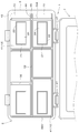
- the hairpin case 1 is divided into a plurality of storage parts by dividing the inside by a partition 4 that is long in the front-rear direction (vertical direction in FIG. 2) and a partition 4 that is long in the left-right direction (left-right direction in FIG. 2).
- the same or different hairpins 8 having a length substantially corresponding to each storage section 9 are stored in the left-right direction in the storage section 9.
- a case cover 7 is detachably attached to the case body 2, and a flange-like flange projecting outward on the outer surface of the right side wall 39 ⁇ / b> A in order to allow the hairpin 8 to be held and opened.
- An opener 3 is provided.
- a partition opener 6 is provided above the partition portion 4 so that the pin can be opened.
- the case main body 2 is a rectangular parallelepiped that is long in the left-right direction, and an upper portion is an opening 42.
- the interior of the case body 2 is partitioned into two front and rear directions by a partition 4 that is long in the left-right direction.
- the two partitioned spaces are divided into three storage portions 9 by two partitions 4 that are long in the front and rear direction. It is divided into. Therefore, the inside of the case body 2 is divided into six storage portions 9, and each storage portion 9 has its left and right directions so as to store various hairpins 8 such as oni pins, bob pins, screw pins, ball pins, and American pins. Are different in length.
- Each partition portion 4 is provided with a partition opener 6 that is thicker below the upper edge portion 5 at the upper portion thereof.
- This thick part has a double side wall structure, and the space 32 formed between the double side walls is open downward.
- the inside of the thick wall portion becomes hollow, that is, the side walls 11A and 11B forming the storage portions 9 are independently formed across the space, and the material forming the partition portion 4 is saved.
- the flange 13 protrudes outward over the entire circumference, and serves as a receiver for the case cover 7 when the case cover 7 is closed.
- a portion of the flange 13 corresponding to the outer surface of the right side wall 39A of the case body 2 is a flange opener 3 having a shape protruding outward.
- the flange opener 3 has two openings 10 in the front-rear direction in the flange portion so that one leg of the hairpin 8 can be inserted.
- the bridging portion 44 formed between the two openings has an effect of increasing the rigidity of the flange opener 3.
- the flange opener 3 has reinforcing triangular pieces 45 formed on both sides in the width direction and below the bridge portion 44. Since one side of the reinforcing triangular piece 45 is fixed to the outer surface of the right side wall 39A, the rigidity of the flange opener 3 is further increased and the leg of the hairpin 8 is easily opened. Even if a large force is applied to the flange opener 3 when the hairpin 8 is opened, there is no inconvenience such as the flange opener 3 being broken from the root because of the reinforcing triangular piece 45.
- a corner portion 17 ⁇ / b> A formed by the inner surface of the bottom wall 12 and the left and right side walls 11 ⁇ / b> A of the storage portion 9 has a substantially arcuate cross section.
- the corner portion 17B formed by the inner surface of the bottom wall 12 and the side wall 11B in the front-rear direction is also substantially arc-shaped in cross section. That is, the corner portions 17A and 17B of the bottom wall 12 of each storage portion 9 are outwardly rounded. Since the corner portion 17A on the inner surface of the bottom wall 12 of the storage portion 9 is rounded, the hairpin 8 can be smoothly taken out without stagnation in the corner portion 17A even if the hairpin 8 is reduced. Further, since the corner portion 17B is rounded, the hairpin 8 is pushed back by the corner portion 17B and is always located at the center portion of the storage portion 9, so that the removal is further facilitated.
- the roundness of the corner portion 17A is preferably larger than the roundness of the corner portion 17B in the left-right direction.
- a sheet-like magnet 23 which is a hairpin magnetized member 20 that attracts the hairpin 8 with a magnetic force, is attached in a band shape.
- the hairpins 8 are separated and magnetically attached one by one to the hairpin magnetized member 20 above the side wall 11 of the storage unit 9, and it is easy to take out the hairpin 8 and there is no need to search for the hairpin 8 with the fingertip. It becomes.
- a step is formed at the boundary between the bottom wall 12 and the sheet-like magnet 23, and the hairpin 8 may be caught there.
- a groove 25 having a depth substantially the same as the thickness of the sheet magnet 23 in the front-rear direction and having substantially the same width as the sheet magnet 23 is formed on the inner surface of the storage portion 9.
- the sheet-like magnet 23 may be attached in a band shape so as to fit into the groove portion 25.
- the sheet-like magnet 23 becomes substantially flush with the inner surface of the storage portion 9, and the hairpin 8 is not easily caught by the boundary.
- the affixing direction of the said hairpin magnetic adhesion member 20 is not limited to the front-back direction, and there is no problem even if it is the left-right direction. You may affix on the whole inner surface of the accommodating part 9.
- an anti-slip member 21 is provided on the bottom surface of the bottom wall 41 of the case body 2. That is, a frame portion 22 is formed at each of the four corners of the lower surface of the bottom wall 41 of the case body 2 in the front-rear and left-right directions, and a rubber 24 is attached to the inside of the frame portion. To protrude.
- the case main body 2 when the case main body 2 is placed at the placement position 48 such as on the wagon stand, the rubber 24 comes into contact with the placement position 48. Therefore, even when the hairpin 8 is taken out or the hairpin 8 is opened by the openers 3 and 6, the case body 2 does not slide on the placement position 48, and the operation can be performed smoothly. Further, when the case main body 2 is placed at a narrow space 48 such as on a wagon base, it is possible to prevent slipping from the case body 2.
- the anti-slip member 21 is not limited to the rubber 24, and there is no problem even if it is a suction cup. Further, the anti-slip member 21 may be provided at one central position of the bottom wall 41 as the pasting position.
- a case cover 7 that opens and closes a case opening 42 of the case body 2 is attached to the case body 2 by two hinges 27 so as to be rotatable.
- the hinge 27 includes a hinge receiving portion 50 provided on the case body 2 and a hinge piece 51 provided on the case cover 7.
- the hinge receiving portion 50 is provided at two locations separated from each other so that the hinge receiving portion 50 is located near both ends of the case opening 42 in the case body 2.
- Each hinge receiving portion 50 has a pair of shaft boss portions 53, 53 that protrude outward from the case body 2 with the fitting space 52 in the center.
- the shaft boss portions 53 and 53 are formed with shaft holes 55 and 55 in which the respective shaft centers coincide with each other (surfaces facing the fitting space 52) facing each other.
- the shaft boss portion 53 and the shaft hole 55 are arranged on the same axis parallel to the side direction of the side portion where the hinge receiving portion 50 is provided, and the axis parallel to the side direction swings relative to the case body 2. It becomes the swinging shaft at the time.
- a hinge piece 51 into which the above-described hinge receiving portion 50 can be fitted is formed on one side portion of the case cover 7.
- the hinge piece 51 is provided on one side of the case cover 7 at two locations at the same interval as the hinge receiving portion 50.
- the hinge piece 51 has a shaft support portion 57 that protrudes outward from the case cover 7.
- the shaft support portion 57 is formed to have a size that can be fitted into the fitting space 52 formed in the hinge receiving portion 50, and the opposite end surfaces of the shaft support portion 57 (the respective shaft bosses of the hinge receiving portion 50).
- Oscillating shafts 58 and 58 that are fitted to the shaft holes 55 and 55 so as to be rotatable in a state in which the respective shaft centers coincide with each other are formed so as to protrude from the surface facing the portions 53 and 53.
- the hinge receiving portion 50 is disposed at a height that can hold the case cover 7 opened from the case body 2 above the case installation surface, in other words, above the bottom surface of the case.
- the shaft boss portions 53 and 53 are formed with notches 60 and 60 that penetrate the shaft holes 55 and 55 downward. These notches 60, 60 are formed so that the opening width is the same or narrower than the hole diameter (diameter) of the shaft holes 55, 55 even at the widest opening width, and the opening width becomes narrower downward.
- the swing shafts 58 and 58 do not open the notches 60 and 60.
- the shaft holes 55 and 55 are engaged and held so as not to be able to escape while maintaining a rotatable state in the shaft holes 55 and 55. That is, the case cover 7 can swing and open with respect to the case body 2.
- hooks 26 for connecting and fixing the case body 2 and the case cover 7 when the cover is closed are provided at two positions on the front left and right sides of the case body 2.
- Protrusions 30 on which the hooks 26 are hooked are provided at two positions on the front surface of the case cover.
- the case cover 7 is provided with outer peripheral ribs 62 so as to surround the outer peripheral portion thereof.
- the outer peripheral rib 62 surrounds the outer peripheral portion of the case opening 42 when the case cover 7 is put on the case opening 42 of the case main body 2.
- the outer peripheral rib 62 surrounds the outer peripheral portion of the bottom wall 41 when the case cover 7 is removed from the case main body 2 and turned over and laid under the bottom wall 41 of the case main body 2.
- the inner surface of the case cover 7 is formed with a restricting portion 15 that protrudes toward the inside of the case body 2 as a state when it is put on the case opening 42 of the case body 2. More specifically, in order to prevent a gap from being generated between the upper edge portion 5 of the partition portion 4 and the inner surface of the case cover 7, the upper edge portion 5 is interposed between the protrusions by two protrusions.
- a groove portion 28 is formed so as to be fitted to each other, and the restricting portion 15 is constituted by the protrusions (groove portion 28) on both sides.
- the case openings 42 (all the storage portions 9) can be closed and the gap formed by the upper edge portion 5 and the inner surface of the case cover 7 can be eliminated. it can. Therefore, even when the case body 2 is moved around, the hairpin 8 does not jump out of the case body 2 and does not fall apart, and the movement (mixing) of the hairpin 8 between the storage units 9 is also prevented. Can be prevented. Further, the restricting portion 15 functions as a reinforcing rib provided on the inner surface of the case cover 7 and increases the rigidity of the case cover 7.
- the upper edge portion 5 that fits into the groove portion 28 is preferably attached with a non-slip rubber 29 at substantially the same height as the case opening 42 on both sides thereof.
- the anti-slip member 21 is provided on the bottom surface of the bottom wall 41 of the case body 2, and the anti-slip member 21 has the case cover 7 removed from the case body 2 and turned over.
- the restricting portion 15 is formed to have a thickness equal to or greater than the height of the restricting portion 15 protruding from the bottom surface of the bottom wall 41 of the case body 2.
- the thickness of the anti-slip member 21 refers to the vertical dimension from the lower surface of the bottom wall 41 of the case body 2 to the lower surface of the anti-slip member 21. Therefore, when the bottom wall 41 is a flat surface, it corresponds to the thickness of the rubber 24. However, when the bottom wall 41 is thickened at the position where the rubber 24 is applied to make the bottom wall 41 bulge downward, this bulging dimension. And the thickness of the rubber 24.
- the hairpin case 1 of the present embodiment described above is made of plastic or the like, and the case main body 2 and the case cover 7 are respectively injection molded. However, it is not limited to this form, and when strength is required, there is no problem even if it is formed by bending and welding a steel plate or the like.
- the hairpins 8 are separated in advance and individually stored in the storage units 9, and the hairpin case 1 is placed at a placement position 48 such as on a wagon table.
- the case cover 7 is detachable from the case main body 2, the case cover 7 is removed and, for example, the hairpin 8 is placed in a region partitioned by the restriction portion 15 on the inner surface of the case cover 7. It can also be used.
- the case cover 7 is opened so as to project to the side of the case main body 2, and the case cover 7 is removed. Press down. By this pressing, the swing shafts 58 and 58 of the hinge piece 51 provided on the case cover 7 are moved downward from the shaft holes 55 and 55 of the hinge receiving portion 50 provided on the case body 2 through the notches 60 and 60.
- the case cover 7 can be easily detached from the case main body 2 as shown in FIG.
- the case cover 7 Since the hinge receiving portion 50 of the case body 2 holds the case cover 7 above the upper surface (case installation surface) of the placement position 48, the case cover 7 is in an open state (before pressing downward). ), The case cover 7 is slanted with the side opposite to the hinge piece 51 placed in contact with the upper surface of the position 48. For this reason, when the case cover 7 is pressed downward, a downward rotational moment with the contact point with the upper surface of the placement position 48 as a fulcrum is efficiently generated in the case cover 7. The downward escape of 58 and 58 can be performed very easily. That is, the case cover 7 can be easily removed from the case body 2.
- the hairpin case 1 is configured such that the bottom wall 41 of the case main body 2 fits inside the case cover 7 (inner region surrounded by the outer peripheral rib 62), as shown in FIG. 7 is placed on the placing position 48 so that the inner surface faces upward (turned over), and the case body 2 is placed so as to be fitted from above (the case cover 7 is placed under the bottom wall 41 of the case body 2). Can be laid).
- the case cover 7 can be placed in the bottom area of the case body 2 so that it can be installed (included), so that the entire area of the hairpin case 1 on the placement position 48 can be made compact. Can be suppressed. That is, it is possible to prevent the hairpin case 1 from interfering with other work (such as putting in and out of hairdressing and beauty tools). Moreover, since the position where the case main body 2 is placed increases as much as the case cover 7 is overlapped, the hairpin 8 can be taken out more easily. In this case, since the case cover 7 may slide on the placement position 48, it is preferable to provide the anti-slip member 21 on the upper surface of the case cover 7 as shown by a two-dot chain line in FIGS.
- the anti-slip member 21 is disposed so as not to contact the restricting portion 15 of the case cover 7 and has a thickness equal to or greater than the protruding height of the restricting portion 15. No backlash occurs during this period, and a stable mounting state can be obtained.
- the finger is moved so as to crawl the inner surface of each storage portion 9 in the front-rear direction so that the desired hairpin 8 is scooped.
- the corner portions 17A and 17B of the bottom wall 12 of each storage portion 9 are outwardly rounded. According to this, since the corner portion 17 is rounded, the hairpin 8 can be smoothly taken out without stagnation in the corner portion 17A even if the hairpin 8 is reduced. Further, due to the roundness of the corner portion 17B, the hairpin 8 is pushed back by the corner portion 17B and is always located at the center portion of the storage portion 9, and the removal thereof is further facilitated.
- a sheet-like magnet 23 is attached in a strip shape in the front-rear direction on the inner surface of each storage unit 9.
- the hairpins 8 are separated and magnetically attached one by one above the side wall 11 of the storage unit 9, so that it is easy to take out the hairpin 8 and it is not necessary to search for the hairpin 8 with the fingertip.
- the leg can be easily opened by being inserted into the partition opener 6 from above.
- hairpins 8 With their short legs upward and sandwiched between the flange openers 3. By rotating these hairpins 8 upward, the short legs are formed.
- the hairpin 8 can be greatly opened by being inserted into the opening 10. That is, the opening of the hairpin 8 can be easily performed by these operations in the openers 3 and 6.
- the hairpin 8 there is also a pin-linked product 35 that is mounted by sandwiching a predetermined number of hairpins with a tape of a predetermined length.
- the pin is rounded and stored in the storage unit 9.
- the pin-connected product 35 is taken out, and a plurality of hairpins 8 are taken out from the tape, and inserted between the flange opener 3 and the partition opener 6. It becomes possible.
- the case body 2 can be considered to slide on the placement position 48.
- the anti-slip member 21 is provided on the bottom surface of the bottom wall 41 of the case body 2, the case body 2 is prevented from sliding on the placement position 48.
- the flange opener 3 is not provided only on the outer side of the right side wall 39 ⁇ / b> A of the case body 2, but may be provided on the entire circumference of the case body side wall 39. Further, it may be provided on two or three surfaces of the side wall 39 of the case body 2. In consideration of a left-handed user, it is preferably provided outside the left side wall 39B.
- the partition openers 6 do not have to be provided in all the partition parts 4, and may be provided only in the front-rear direction partition part 4 or only in the left-right direction partition part 4. There is no problem even if it is provided in only one partition in the case body 2.
- the hairpin opener is not limited to the partition opener 6 and the flange opener 3, and there is no problem even if the case cover 7 is formed as a single plate and the side end thereof is used as the opener.
- the hairpin case 1 of this embodiment is provided with both the flange opener 3 and the partition opener 6, it does not necessarily need to have both, and even if it is the structure which has only one of them, there is no problem. There is no. Further, the storage unit 9 has different lengths in the left-right direction so that various hairpins can be stored, but it may have the same length in the left-right direction. Conversely, there is no problem even if the lengths are different in the vertical direction.
- the partition part 4 which forms the accommodating part 9 does not need to have a double side wall structure, and may be a single plate with a non-slip rubber 29 attached to both sides of the upper edge part 5.
- One plate may be provided with protrusions on both sides of the upper edge portion 5.
- the restriction portion 15 formed on the inner surface of the case cover 7 does not need to be the ridge groove portion 28, and there is no problem even if it is a single ridge that is attached to the upper edge portion 5. In other words, even the protrusion restricting portion 15 can restrict the movement of the hairpin 8 between the storage portions 9.
Landscapes
- Purses, Travelling Bags, Baskets, Or Suitcases (AREA)
Abstract
The present invention allows hair pins to be inserted and stored or stored with the prongs open in a main case body that accommodates hair pins, and facilitates the handling of the hair pins.
In a main case body (2) wherein the interior is divided by partitions (4) in the fore-aft direction and/or the left-right direction to form multiple receptacles (9), a flange-shaped flange opener (3) protruding outward from the outer surface of a side wall (39), which allows clipping and prong-opening of hair pins (8), is provided and/or a partition opener (6) is provided at the top of a partition (4) so as to be thicker below than at the upper edge (5).
Description
本発明は、髪形をセットする際に使用するヘアピンを収納するヘアピンケースに関するものである。
The present invention relates to a hairpin case that houses a hairpin used when setting a hairstyle.
人の頭髪を所望の髪型に保持させるためのものとして、従来よりヘアピンが用いられている。このヘアピンを多数使用する美容院や美容技術学校において、美容師(理容師を含む)は使い勝手を考え、ヘアピンを同種ごとに分けた上で既成のケースに収納し、調髪作業をするときはそのケースから必要な本数取り出して使用している。
ヘアピンを収納するケースには、例えば特許文献1等に開示されるような、仕切部材でケース内が複数の収納区画に仕切られたものが知られている。このケースの開口には揺動することで開閉する蓋が設けられており、ケース内は閉鎖可能となっている。 Conventionally, a hairpin has been used to hold a human hair in a desired hairstyle. In beauty salons and beauty technical schools that use a large number of hairpins, hairdressers (including barbers) think about usability, divide the hairpins into the same type, store them in a ready-made case, The necessary number is taken out from the case and used.
As a case for storing a hairpin, a case in which the inside of the case is partitioned into a plurality of storage compartments by a partition member as disclosed in, for example,Patent Document 1 is known. A lid that opens and closes by swinging is provided at the opening of the case, and the inside of the case can be closed.
ヘアピンを収納するケースには、例えば特許文献1等に開示されるような、仕切部材でケース内が複数の収納区画に仕切られたものが知られている。このケースの開口には揺動することで開閉する蓋が設けられており、ケース内は閉鎖可能となっている。 Conventionally, a hairpin has been used to hold a human hair in a desired hairstyle. In beauty salons and beauty technical schools that use a large number of hairpins, hairdressers (including barbers) think about usability, divide the hairpins into the same type, store them in a ready-made case, The necessary number is taken out from the case and used.
As a case for storing a hairpin, a case in which the inside of the case is partitioned into a plurality of storage compartments by a partition member as disclosed in, for example,
なお、ヘアピンを髪に取り付ける際、美容師はヘアピンを開脚させ、その間に固定したい髪の毛を挟み込むようにしている。そのため、装着時には、ヘアピンの脚に指や爪で力を加えることで開脚させたり、口や歯で片脚を銜えつつもう一方の片脚を指で開いたりしていた。
When attaching a hairpin to the hair, the hairdresser opens the leg of the hairpin and sandwiches the hair to be fixed between them. For this reason, at the time of wearing, the legs of the hairpin were opened by applying force with fingers or nails, or the other leg was opened with a finger while holding one leg with the mouth or teeth.
しかしながら、ヘアピンを指や爪で力を加え開脚させる操作は効率が悪い上に、ヘアピンを口でくわえて開脚させることは非常に不衛生である。
一方、美容師が調髪作業をするに際しヘアピンをケースに対して出し入れするには、美容師の近傍に設置するワゴン台の上へ理美容道具類(櫛やブラシ、化粧水など)などと一緒に、ケースを並べておく必要がある。このとき、ケースは、蓋が開いたままの状態で使用する方が、ヘアピンを取り出しやすい。ところが、ワゴン台の上のスペースは一般に非常に限られているため、蓋を開放状態のままにしておくと、ケースを置くのに底面積の約2倍のスペースを占有することになる。つまり、蓋を開放状態のままにしてケースを使用することは、他の理美容道具類の出し入れを考えた場合に非常に作業性を低下させる原因になる。 However, the operation of opening the hairpin by applying force with fingers or nails is inefficient and it is very unsanitary to open the hairpin with the mouth.
On the other hand, in order to put hairpins in and out of the case when the hairdresser performs hairdressing work, on the wagon stand installed near the hairdresser, along with hairdressing tools (comb, brush, lotion, etc.) , You need to line up cases. At this time, it is easier to take out the hairpin when the case is used with the lid open. However, the space above the wagon base is generally very limited, so if the lid is left open, it will occupy about twice the bottom area to place the case. In other words, using the case with the lid open can cause a significant decrease in workability when taking in and out other barber / beauty tools.
本発明は上記事情に鑑みてなされたものであって、ヘアピンの開脚及び取り扱いが容易に行えるようにすると共に、蓋を開放状態のままにして使用する際にも、スペースを取ることなく、他の作業の邪魔になることがないヘアピンケースを提供することを目的とする。
The present invention was made in view of the above circumstances, and makes it easy to open and handle the hairpin, and when using it with the lid open, without taking up space, An object of the present invention is to provide a hairpin case that does not interfere with other operations.
前記目的を達成するために、本発明は次の手段を講じた。
即ち、本発明における課題解決のための第1の具体的手段は、内部を前後方向及び/又は左右方向の仕切部で区画して複数の収納部を形成したケース本体に、ヘアピンの差し挟み保持及び開脚を可能にすべく、側壁外面に外方突出したフランジ状のフランジオープナーを設け、及び/又は、前記仕切部の上部に上縁部より下方部で厚肉となる仕切オープナーを設けていることである。 In order to achieve the above object, the present invention has taken the following measures.
That is, the first specific means for solving the problems in the present invention is to hold the hairpin between the case main body in which the interior is partitioned by the front and rear and / or left and right partition sections to form a plurality of storage sections. In order to enable the legs to open, a flange-shaped flange opener protruding outward is provided on the outer surface of the side wall, and / or a partition opener that is thicker below the upper edge than the upper edge is provided on the upper part of the partition. It is that you are.
これにより、ケース本体内の複数の収納部に、予め分別したヘアピンを個別に収納できるようになる。また、フランジオープナー及び/又は仕切オープナーを用いることでヘアピンの開脚が容易に行えると共に、オープナーに複数のヘアピンを差し挟みこんで保持することができるようになる。
本発明における課題解決のための第2の具体的手段は、前記ケース本体には、上方のケース開口を開閉自在にするケースカバーが設けられており、ケース本体にはケース開口の一辺部にこの辺方向と平行な軸孔を備えたヒンジ受部が設けられていると共に、ケースカバーには前記ヒンジ受部の軸孔に回動自在に嵌合する揺動軸を備えたヒンジ片が設けられて、これらヒンジ受部とヒンジ片とによってケース本体とケースカバーとが揺動自在に連結されており、前記ヒンジ受部は、ケース本体から開いたケースカバーをケース設置面より上方で保持可能な高さに配備され、且つ、この開いたケースカバーを下方へ押圧したときにヒンジ片の揺動軸を下方へ脱出させるが非押圧時には揺動軸を係合保持する開口大きさで前記軸孔を下方へ貫通させた切欠が形成されたものとすることである。 Thereby, the hairpin classified beforehand can be separately accommodated in the some accommodating part in a case main body. Further, by using the flange opener and / or the partition opener, the hairpin can be easily opened, and a plurality of hairpins can be sandwiched and held in the opener.
According to a second specific means for solving the problems in the present invention, the case main body is provided with a case cover that allows the upper case opening to be opened and closed. A hinge receiving portion having a shaft hole parallel to the direction is provided, and a hinge piece having a swing shaft that is rotatably fitted to the shaft hole of the hinge receiving portion is provided on the case cover. The case main body and the case cover are swingably connected by the hinge receiving portion and the hinge piece, and the hinge receiving portion is a height capable of holding the case cover opened from the case main body above the case installation surface. When the open case cover is pressed downward, the swinging shaft of the hinge piece escapes downward, but when not pressed, the shaft hole is opened with an opening size that engages and holds the swinging shaft. Pierce downward It is that it is assumed that the notch is formed.
これにより、ヒンジ受部に対してヒンジ軸を回動させるようにしてケースカバーを揺動させ、ケース本体上へ被せることで、ケース本体内に形成された収納部を閉じることができる。したがって、ケース本体を持ち歩くなどして移動させた場合でも、ケース本体内(収納部)からヘアピンが外に飛び出てバラバラになるのを防止できる。
さらに、このケースカバーをワゴン台などの上面のように平坦な載置面の上に置き、ケース本体に対してケースカバーを閉鎖状態から全開まで開いてゆくと、ケースカバーの一部が載置面に接触するようになる。このとき、ヒンジ片が設けられていない側のケースカバーの端部はケース本体の設置面(載置面)に接触するが、ヒンジ片が設けられた側のケースカバーの端部はケース本体の設置面(載置面)より上方に吊り上がった状態に保持される。つまり、ケースカバーは、一方の端部を設置面に接触させた状態でもう一方の端部が持ち上げられた状態にあるため、ヒンジ片が設けられた側のケースカバーの端部を下方へ押圧すると、テコの原理で強い力が作用しヒンジ受部の切欠からヒンジ片の揺動軸を下方に簡単に脱出させることができ、大きな力を必要とすることなくケースカバーをケース本体から取り外す(分離させる)ことができる。次に、このようにして取り外したケースカバーをケース本体の下方へ敷くと、ケース本体の底面積内にケースカバーを重ね合わせて(含ませて)設置することができるので、蓋を開放状態のままにして使用する際にも、スペースを取ることなく、他の作業の邪魔になることもない。 Thereby, the case cover can be swung so as to rotate the hinge shaft with respect to the hinge receiving portion, and the case cover is placed on the case main body, whereby the storage portion formed in the case main body can be closed. Accordingly, even when the case main body is carried around and moved, the hairpin can be prevented from jumping out from the case main body (storage portion) and falling apart.
Furthermore, when this case cover is placed on a flat mounting surface such as the upper surface of a wagon stand or the like, and the case cover is opened from the closed state to the fully opened state, a part of the case cover is placed. It comes in contact with the surface. At this time, the end of the case cover on the side where the hinge piece is not provided is in contact with the installation surface (mounting surface) of the case body, but the end of the case cover on the side where the hinge piece is provided is the end of the case body. It is held in a state of being lifted upward from the installation surface (mounting surface). In other words, the case cover is in a state in which one end is in contact with the installation surface and the other end is lifted, so the end of the case cover on the side where the hinge piece is provided is pressed downward. Then, a strong force is applied according to the lever principle, and the swing shaft of the hinge piece can be easily moved downward from the notch of the hinge receiving portion, and the case cover is removed from the case body without requiring a large force ( Can be separated). Next, when the case cover removed in this way is laid below the case body, the case cover can be placed in the bottom area of the case body so that it can be installed (included), so that the lid is opened. Even if it is used as it is, it does not take up space and does not interfere with other work.
本発明における課題解決のための第3の具体的手段は、前記ケースカバーには、ケース本体のケース開口上に被せられたときにはケース開口の外周部を取り囲み且つ裏返し状態でケース本体の底壁下部に敷かれたときには底壁の外周部を取り囲む外周リブが設けられていると共に、ケース本体のケース開口上に被せられたときにケース本体内へ突出してヘアピンの収納部間移動を規制する規制部が設けられており、前記ケース本体の底壁下面には、ケースカバーに設けられた規制部の突出高さと同等以上の厚さを有した滑り止め部材が設けられたものとすることである。
According to a third specific means for solving the problem in the present invention, the case cover surrounds the outer periphery of the case opening when the case cover is put on the case opening of the case main body and is turned upside down. The outer peripheral rib that surrounds the outer peripheral portion of the bottom wall is provided when laid on, and the restriction portion that protrudes into the case main body and restricts the movement of the hairpin between the storage portions when it is put on the case opening of the case main body And a non-slip member having a thickness equal to or greater than the protruding height of the restricting portion provided on the case cover is provided on the lower surface of the bottom wall of the case body.
このように、ヘアピンが収納部間で移動することを規制する規制部をケースカバーの内面に形成すれば、ケースカバーをケース本体に被せた際に仕切部の上縁部とケースカバー内面との間に隙間が生じ難くなり、ケース本体を持ち歩くなどして移動させた場合でも各収納部間でヘアピン同士が混ざり合うことを防ぐことができる。
一方、ケース本体の底壁下面に滑り止め部材を設けることで、ヘアピンを取り出したり、各オープナーで開脚させるときにケース本体がワゴン台上等の置き位置上を滑ることが無くなる。特に、ケース本体がワゴン台などの狭いスペースに置かれている場合、そこからの滑り落ちを防止できる。 In this way, if the restricting portion that restricts the movement of the hairpin between the storage portions is formed on the inner surface of the case cover, when the case cover is put on the case main body, the upper edge portion of the partition portion and the inner surface of the case cover It becomes difficult to generate a gap between them, and even when the case body is carried around and moved, hairpins can be prevented from being mixed between the storage units.
On the other hand, by providing a non-slip member on the bottom wall bottom surface of the case main body, the case main body does not slide on the placing position such as on the wagon stand when the hairpin is taken out or opened by each opener. In particular, when the case body is placed in a narrow space such as a wagon stand, slipping from the case body can be prevented.
この滑り止め部材の厚さは、規制部の突出高さより同等以上としておくことで、ケースカバーをケース本体の下方へ敷くときに、規制部がケース本体の底壁下面に当接しない状態にでき、ケースカバーとケース本体との間にガタツキが発生するのを防止できるものである。
The thickness of the anti-slip member is set to be equal to or greater than the protruding height of the restricting portion so that the restricting portion does not contact the lower surface of the bottom wall of the case main body when the case cover is laid below the case main body. It is possible to prevent rattling from occurring between the case cover and the case body.
本発明に係るヘアピンケースでは、蓋を開放状態のままにして使用する際にも、スペースを取ることなく、他の作業の邪魔になることがない。
The hairpin case according to the present invention does not obstruct other work without taking up space even when used with the lid open.
以下、本発明の実施の形態を、図面に基づき説明する。
図1~8において、ヘアピンケース1は、内部を前後方向(図2の上下方向)に長い仕切部4及び左右方向(図2の左右方向)に長い仕切部4で区画して複数の収納部9を形成したケース本体2を有し、この収納部9内の左右方向の向きに、各収納部9にほぼ対応した長さを有する同種又は異種のヘアピン8がそれぞれ収納されている。 Hereinafter, embodiments of the present invention will be described with reference to the drawings.
1 to 8, thehairpin case 1 is divided into a plurality of storage parts by dividing the inside by a partition 4 that is long in the front-rear direction (vertical direction in FIG. 2) and a partition 4 that is long in the left-right direction (left-right direction in FIG. 2). The same or different hairpins 8 having a length substantially corresponding to each storage section 9 are stored in the left-right direction in the storage section 9.
図1~8において、ヘアピンケース1は、内部を前後方向(図2の上下方向)に長い仕切部4及び左右方向(図2の左右方向)に長い仕切部4で区画して複数の収納部9を形成したケース本体2を有し、この収納部9内の左右方向の向きに、各収納部9にほぼ対応した長さを有する同種又は異種のヘアピン8がそれぞれ収納されている。 Hereinafter, embodiments of the present invention will be described with reference to the drawings.
1 to 8, the
このケース本体2には、ケースカバー7が着脱自在に取り付けられていると共に、ヘアピン8の差し挟み保持及び開脚を可能にするために、右側壁39A外面に外方へ突出したフランジ状のフランジオープナー3が設けられている。また、仕切部4の上方には、同じくピン開脚を可能とすべく仕切オープナー6が設けられている。
詳しくは、図2~5に示すように、ケース本体2は左右方向に長い直方体であり、上方が開口部42となっている。ケース本体2の内部は、左右方向に長い仕切部4で前後方向2つに区画されており、さらに、区画された2つの空間は、前後方向に長い2つの仕切部4により3つの収納部9に区画されている。したがって、このケース本体2の内部は6つの収納部9に区画され、さらに、各収納部9はオニピン、ボブピン、ネジピン、玉付きピン、アメリカピン等の各種ヘアピン8を収納できるようにその左右方向の長さが異なっている。 Acase cover 7 is detachably attached to the case body 2, and a flange-like flange projecting outward on the outer surface of the right side wall 39 </ b> A in order to allow the hairpin 8 to be held and opened. An opener 3 is provided. In addition, a partition opener 6 is provided above the partition portion 4 so that the pin can be opened.
Specifically, as shown in FIGS. 2 to 5, the casemain body 2 is a rectangular parallelepiped that is long in the left-right direction, and an upper portion is an opening 42. The interior of the case body 2 is partitioned into two front and rear directions by a partition 4 that is long in the left-right direction. Further, the two partitioned spaces are divided into three storage portions 9 by two partitions 4 that are long in the front and rear direction. It is divided into. Therefore, the inside of the case body 2 is divided into six storage portions 9, and each storage portion 9 has its left and right directions so as to store various hairpins 8 such as oni pins, bob pins, screw pins, ball pins, and American pins. Are different in length.
詳しくは、図2~5に示すように、ケース本体2は左右方向に長い直方体であり、上方が開口部42となっている。ケース本体2の内部は、左右方向に長い仕切部4で前後方向2つに区画されており、さらに、区画された2つの空間は、前後方向に長い2つの仕切部4により3つの収納部9に区画されている。したがって、このケース本体2の内部は6つの収納部9に区画され、さらに、各収納部9はオニピン、ボブピン、ネジピン、玉付きピン、アメリカピン等の各種ヘアピン8を収納できるようにその左右方向の長さが異なっている。 A
Specifically, as shown in FIGS. 2 to 5, the case
それぞれの仕切部4には、その上部に、上縁部5より下方部で厚肉となる仕切オープナー6が設けられている。この厚肉部位は二重側壁構造であり、二重側壁間に形成される空間32は下方に開放される構造となっている。これにより厚肉部位の内部は中空となり、すなわち、各収納部9を形成する側壁11A,11Bは空間を挟んで独立して形成され、仕切部4を形成する材料を節減している。
Each partition portion 4 is provided with a partition opener 6 that is thicker below the upper edge portion 5 at the upper portion thereof. This thick part has a double side wall structure, and the space 32 formed between the double side walls is open downward. As a result, the inside of the thick wall portion becomes hollow, that is, the side walls 11A and 11B forming the storage portions 9 are independently formed across the space, and the material forming the partition portion 4 is saved.
ケース本体2の側壁39でケース開口42よりやや下がった位置には、全周に渡ってフランジ13が外方に突出しており、ケースカバー7閉蓋時に、ケースカバー7の受けになっている。
前記フランジ13の内、ケース本体2の右側壁39Aの外面にあたる部位は、さらに外方へ突出した形状のフランジオープナー3となっている。このフランジオープナー3は、そのフランジ部において、ヘアピン8の片脚を挿入することが可能な大きさの開口部10を前後方向に2つ有している。この2つの開口部の間に形成される架橋部44は、フランジオープナー3の剛性を増加させる作用を奏している。 At a position slightly lower than the case opening 42 on the side wall 39 of thecase body 2, the flange 13 protrudes outward over the entire circumference, and serves as a receiver for the case cover 7 when the case cover 7 is closed.
A portion of theflange 13 corresponding to the outer surface of the right side wall 39A of the case body 2 is a flange opener 3 having a shape protruding outward. The flange opener 3 has two openings 10 in the front-rear direction in the flange portion so that one leg of the hairpin 8 can be inserted. The bridging portion 44 formed between the two openings has an effect of increasing the rigidity of the flange opener 3.
前記フランジ13の内、ケース本体2の右側壁39Aの外面にあたる部位は、さらに外方へ突出した形状のフランジオープナー3となっている。このフランジオープナー3は、そのフランジ部において、ヘアピン8の片脚を挿入することが可能な大きさの開口部10を前後方向に2つ有している。この2つの開口部の間に形成される架橋部44は、フランジオープナー3の剛性を増加させる作用を奏している。 At a position slightly lower than the case opening 42 on the side wall 39 of the
A portion of the
このフランジオープナー3には、その幅方向両側と架橋部44の下側に補強三角片45が形成されている。この補強三角片45の一辺は右側壁39Aの外面に固着しているため、フランジオープナー3の剛性がさらに増すこととなりヘアピン8の開脚を容易にする。また、ヘアピン8の開脚時に大きな力がフランジオープナー3に加わったとしても、かかる補強三角片45があるため、フランジオープナー3が根本から折れるなどの不都合を生じることはない。
The flange opener 3 has reinforcing triangular pieces 45 formed on both sides in the width direction and below the bridge portion 44. Since one side of the reinforcing triangular piece 45 is fixed to the outer surface of the right side wall 39A, the rigidity of the flange opener 3 is further increased and the leg of the hairpin 8 is easily opened. Even if a large force is applied to the flange opener 3 when the hairpin 8 is opened, there is no inconvenience such as the flange opener 3 being broken from the root because of the reinforcing triangular piece 45.
図3,4に示すように、前記収納部9の底壁12内面と左右方向側壁11Aにより形成されるコーナー部17Aが断面略円弧状となっている。さらに、底壁12内面と前後方向側壁11Bにより形成されるコーナー部17Bも断面略円弧状となっている。すなわち、各収納部9の底壁12のコーナー部17A,17Bは外向きに丸みを有している。
収納部9の底壁12内面のコーナー部17Aが丸みを帯びているため、ヘアピン8が少なくなっても、このコーナー部17Aに滞ることなくヘアピン8をスムーズに取り出せるようになる。また、コーナー部17Bが丸みを帯びているため、ヘアピン8がコーナー部17Bで押し戻され、常に収納部9の中央部に位置するようになり、その取り出しがさらに容易になる。 As shown in FIGS. 3 and 4, a corner portion 17 </ b> A formed by the inner surface of thebottom wall 12 and the left and right side walls 11 </ b> A of the storage portion 9 has a substantially arcuate cross section. Further, the corner portion 17B formed by the inner surface of the bottom wall 12 and the side wall 11B in the front-rear direction is also substantially arc-shaped in cross section. That is, the corner portions 17A and 17B of the bottom wall 12 of each storage portion 9 are outwardly rounded.
Since thecorner portion 17A on the inner surface of the bottom wall 12 of the storage portion 9 is rounded, the hairpin 8 can be smoothly taken out without stagnation in the corner portion 17A even if the hairpin 8 is reduced. Further, since the corner portion 17B is rounded, the hairpin 8 is pushed back by the corner portion 17B and is always located at the center portion of the storage portion 9, so that the removal is further facilitated.
収納部9の底壁12内面のコーナー部17Aが丸みを帯びているため、ヘアピン8が少なくなっても、このコーナー部17Aに滞ることなくヘアピン8をスムーズに取り出せるようになる。また、コーナー部17Bが丸みを帯びているため、ヘアピン8がコーナー部17Bで押し戻され、常に収納部9の中央部に位置するようになり、その取り出しがさらに容易になる。 As shown in FIGS. 3 and 4, a corner portion 17 </ b> A formed by the inner surface of the
Since the
なお、前後方向のコーナー部17Aの丸みが大きいほどヘアピン8を取り出しやすくなるため、前記コーナー部17Aの丸みは、左右方向のコーナー部17Bの丸みより大きいことが好ましい。
加えて、各収納部9の内面で前後方向には、ヘアピン8を磁力で吸着するヘアピン磁着部材20であるシート状マグネット23が帯状に貼り付けてある。これにより、収納部9の側壁11上方のヘアピン磁着部材20にヘアピン8が一本ずつ分離して磁着することになり、ヘアピン8を取り出しやすくなる上に指先でヘアピン8を探す手間が不要となる。 In addition, since it becomes easier to take out thehairpin 8 as the roundness of the corner portion 17A in the front-rear direction is larger, the roundness of the corner portion 17A is preferably larger than the roundness of the corner portion 17B in the left-right direction.
In addition, in the front-rear direction on the inner surface of eachstorage unit 9, a sheet-like magnet 23, which is a hairpin magnetized member 20 that attracts the hairpin 8 with a magnetic force, is attached in a band shape. As a result, the hairpins 8 are separated and magnetically attached one by one to the hairpin magnetized member 20 above the side wall 11 of the storage unit 9, and it is easy to take out the hairpin 8 and there is no need to search for the hairpin 8 with the fingertip. It becomes.
加えて、各収納部9の内面で前後方向には、ヘアピン8を磁力で吸着するヘアピン磁着部材20であるシート状マグネット23が帯状に貼り付けてある。これにより、収納部9の側壁11上方のヘアピン磁着部材20にヘアピン8が一本ずつ分離して磁着することになり、ヘアピン8を取り出しやすくなる上に指先でヘアピン8を探す手間が不要となる。 In addition, since it becomes easier to take out the
In addition, in the front-rear direction on the inner surface of each
ここで、シート状マグネット23を単に収納部9内面に貼り付ける構成を採用すると、底壁12とシート状マグネット23の境目に段差ができ、そこにヘアピン8が引っ掛かることがある。これを防ぐため、好ましくは、収納部9の内面で前後方向にシート状マグネット23の厚さとほぼ同一の深さで、かつ、シート状マグネット23とほぼ同一幅を有する溝部25を形成し、この溝部25に嵌り込むように、シート状マグネット23が帯状に貼り付けるとよい。
Here, if the configuration in which the sheet-like magnet 23 is simply attached to the inner surface of the storage portion 9 is adopted, a step is formed at the boundary between the bottom wall 12 and the sheet-like magnet 23, and the hairpin 8 may be caught there. In order to prevent this, preferably, a groove 25 having a depth substantially the same as the thickness of the sheet magnet 23 in the front-rear direction and having substantially the same width as the sheet magnet 23 is formed on the inner surface of the storage portion 9. The sheet-like magnet 23 may be attached in a band shape so as to fit into the groove portion 25.
これにより、シート状マグネット23は収納部9内面とほぼ面一になり、ヘアピン8がその境目に引っ掛かり取りづらくなるといったことが無くなる。
なお、前記ヘアピン磁着部材20の貼り付け方向は前後方向に限定されるものではなく、左右方向であっても問題はない。収納部9内面の全面に貼り付けてあってもよい。
さらに、図5に示すように、ケース本体2の底壁41下面には滑り止め部材21が設けてある。すなわち、ケース本体2の底壁41下面のそれぞれ前後左右方向4隅には、枠部22が形成されており、その中側にゴム24が貼り付けられて、その枠部22よりゴム24が下方に突出するようになっている。 Thereby, the sheet-like magnet 23 becomes substantially flush with the inner surface of the storage portion 9, and the hairpin 8 is not easily caught by the boundary.
In addition, the affixing direction of the said hairpinmagnetic adhesion member 20 is not limited to the front-back direction, and there is no problem even if it is the left-right direction. You may affix on the whole inner surface of the accommodating part 9. FIG.
Further, as shown in FIG. 5, ananti-slip member 21 is provided on the bottom surface of the bottom wall 41 of the case body 2. That is, a frame portion 22 is formed at each of the four corners of the lower surface of the bottom wall 41 of the case body 2 in the front-rear and left-right directions, and a rubber 24 is attached to the inside of the frame portion. To protrude.
なお、前記ヘアピン磁着部材20の貼り付け方向は前後方向に限定されるものではなく、左右方向であっても問題はない。収納部9内面の全面に貼り付けてあってもよい。
さらに、図5に示すように、ケース本体2の底壁41下面には滑り止め部材21が設けてある。すなわち、ケース本体2の底壁41下面のそれぞれ前後左右方向4隅には、枠部22が形成されており、その中側にゴム24が貼り付けられて、その枠部22よりゴム24が下方に突出するようになっている。 Thereby, the sheet-
In addition, the affixing direction of the said hairpin
Further, as shown in FIG. 5, an
したがって、ケース本体2をワゴン台上等の置き位置48に置いた場合に、このゴム24が置き位置48と接触することになる。そのため、ヘアピン8を取り出したりオープナー3,6でヘアピン8を開脚させるときにも、ケース本体2が置き位置48上を滑ることが無くなり、作業をスムーズに行える。また、ケース本体2がワゴン台上など、スペース的に狭い置き位置48に置かれている場合、そこからの滑り落ちをも防止できる。
Therefore, when the case main body 2 is placed at the placement position 48 such as on the wagon stand, the rubber 24 comes into contact with the placement position 48. Therefore, even when the hairpin 8 is taken out or the hairpin 8 is opened by the openers 3 and 6, the case body 2 does not slide on the placement position 48, and the operation can be performed smoothly. Further, when the case main body 2 is placed at a narrow space 48 such as on a wagon base, it is possible to prevent slipping from the case body 2.
なお、この滑り止め部材21はゴム24に限定されるものではなく、吸盤などであっても何ら問題はない。また、貼り付け位置は、底壁41の中央1カ所に滑り止め部材21を設けるものであってもよい。
ケース本体2には、ケース本体2のケース開口42を開閉するケースカバー7が、本体2に2つのヒンジ27により回動自在に取り付けられている。このヒンジ27は、ケース本体2に設けられたヒンジ受部50と、ケースカバー7に設けられたヒンジ片51とによって構成されている。 Theanti-slip member 21 is not limited to the rubber 24, and there is no problem even if it is a suction cup. Further, the anti-slip member 21 may be provided at one central position of the bottom wall 41 as the pasting position.
Acase cover 7 that opens and closes a case opening 42 of the case body 2 is attached to the case body 2 by two hinges 27 so as to be rotatable. The hinge 27 includes a hinge receiving portion 50 provided on the case body 2 and a hinge piece 51 provided on the case cover 7.
ケース本体2には、ケース本体2のケース開口42を開閉するケースカバー7が、本体2に2つのヒンジ27により回動自在に取り付けられている。このヒンジ27は、ケース本体2に設けられたヒンジ受部50と、ケースカバー7に設けられたヒンジ片51とによって構成されている。 The
A
ヒンジ受部50は、ケース本体2におけるケース開口42の一辺部に対して、その両端寄りの配置となるように、離反した2箇所に設けられている。それぞれのヒンジ受部50は、嵌合用空間52を中央に挟んでケース本体2の外方へ突出する一対の軸ボス部53,53を有している。これら軸ボス部53,53には、互いに対向する部分(嵌合用空間52に向く面)に、互いの軸心を一致させた軸孔55,55が形成されている。
The hinge receiving portion 50 is provided at two locations separated from each other so that the hinge receiving portion 50 is located near both ends of the case opening 42 in the case body 2. Each hinge receiving portion 50 has a pair of shaft boss portions 53, 53 that protrude outward from the case body 2 with the fitting space 52 in the center. The shaft boss portions 53 and 53 are formed with shaft holes 55 and 55 in which the respective shaft centers coincide with each other (surfaces facing the fitting space 52) facing each other.
これらの軸ボス部53及び軸孔55はヒンジ受部50が設けられた辺部の辺方向と平行な同軸上に並んでおり、この辺方向と平行な軸がケース本体2に対して揺動する際の揺動軸となる。
これに対し、ケースカバー7の一辺部には、前記したヒンジ受部50を嵌合可能なヒンジ片51が形成されている。ヒンジ片51は、ケースカバー7の一辺部に、ヒンジ受部50と同じ間隔をあけて2箇所に亘って設けられている。ヒンジ片51は、ケースカバー7の外方へ突出する軸支持部57を有している。この軸支持部57は、ヒンジ受部50に形成された嵌合用空間52に嵌合可能な大きさで形成されており、この軸支持部57の相反する端面(ヒンジ受部50の各軸ボス部53,53へ向く面)に、互いの軸心を一致させる状態で、軸孔55,55に回動自在な状態として嵌合する揺動軸58,58が突出形成されている。 Theshaft boss portion 53 and the shaft hole 55 are arranged on the same axis parallel to the side direction of the side portion where the hinge receiving portion 50 is provided, and the axis parallel to the side direction swings relative to the case body 2. It becomes the swinging shaft at the time.
On the other hand, ahinge piece 51 into which the above-described hinge receiving portion 50 can be fitted is formed on one side portion of the case cover 7. The hinge piece 51 is provided on one side of the case cover 7 at two locations at the same interval as the hinge receiving portion 50. The hinge piece 51 has a shaft support portion 57 that protrudes outward from the case cover 7. The shaft support portion 57 is formed to have a size that can be fitted into the fitting space 52 formed in the hinge receiving portion 50, and the opposite end surfaces of the shaft support portion 57 (the respective shaft bosses of the hinge receiving portion 50). Oscillating shafts 58 and 58 that are fitted to the shaft holes 55 and 55 so as to be rotatable in a state in which the respective shaft centers coincide with each other are formed so as to protrude from the surface facing the portions 53 and 53.
これに対し、ケースカバー7の一辺部には、前記したヒンジ受部50を嵌合可能なヒンジ片51が形成されている。ヒンジ片51は、ケースカバー7の一辺部に、ヒンジ受部50と同じ間隔をあけて2箇所に亘って設けられている。ヒンジ片51は、ケースカバー7の外方へ突出する軸支持部57を有している。この軸支持部57は、ヒンジ受部50に形成された嵌合用空間52に嵌合可能な大きさで形成されており、この軸支持部57の相反する端面(ヒンジ受部50の各軸ボス部53,53へ向く面)に、互いの軸心を一致させる状態で、軸孔55,55に回動自在な状態として嵌合する揺動軸58,58が突出形成されている。 The
On the other hand, a
すなわち、ケース本体2に設けられたヒンジ受部50の軸孔55,55と、ケースカバー7に設けられたヒンジ片51の揺動軸58,58とを互いに嵌合させることにより、ケース本体2とケースカバー7とが揺動自在に連結されている。
前記ヒンジ受部50は、ケース本体2から開いたケースカバー7をケース設置面、言い換えればケースの底面より上方で保持可能な高さに配備されている。そして、軸ボス部53,53には、軸孔55,55を下方へ貫通させた切欠60,60が形成されている。これら切欠60,60は、開口幅が最も広い部分でも軸孔55,55の孔径(直径)と同等か又は狭く、尚かつ、下方へゆくほど開口幅が狭くなるように形成されている。 That is, by fitting the shaft holes 55 and 55 of thehinge receiving portion 50 provided in the case main body 2 and the swing shafts 58 and 58 of the hinge piece 51 provided in the case cover 7 together, the case main body 2 And the case cover 7 are swingably connected.
Thehinge receiving portion 50 is disposed at a height that can hold the case cover 7 opened from the case body 2 above the case installation surface, in other words, above the bottom surface of the case. The shaft boss portions 53 and 53 are formed with notches 60 and 60 that penetrate the shaft holes 55 and 55 downward. These notches 60, 60 are formed so that the opening width is the same or narrower than the hole diameter (diameter) of the shaft holes 55, 55 even at the widest opening width, and the opening width becomes narrower downward.
前記ヒンジ受部50は、ケース本体2から開いたケースカバー7をケース設置面、言い換えればケースの底面より上方で保持可能な高さに配備されている。そして、軸ボス部53,53には、軸孔55,55を下方へ貫通させた切欠60,60が形成されている。これら切欠60,60は、開口幅が最も広い部分でも軸孔55,55の孔径(直径)と同等か又は狭く、尚かつ、下方へゆくほど開口幅が狭くなるように形成されている。 That is, by fitting the shaft holes 55 and 55 of the
The
従って、ケース本体2に対して開いた状態とさせたケースカバー7を下方へ押圧したときには、ヒンジ片51の揺動軸58,58が切欠60,60の内面を押し開くようになって、揺動軸58,58は下方へ脱出する。そのため、これによってケース本体2からケースカバー7を取り外すことが可能となっている。なお、言うまでもなく、ケースカバー7の取り外し後において、揺動軸58,58を切欠60,60の下方に合致させ、上方へ押し上げるようにすることで、揺動軸58,58を軸ボス部53,53へ嵌め入れることができるようになっている。
Therefore, when the case cover 7 opened to the case body 2 is pressed downward, the swinging shafts 58 and 58 of the hinge piece 51 push open the inner surfaces of the notches 60 and 60, and the swinging is performed. The moving shafts 58 and 58 escape downward. Therefore, it is possible to remove the case cover 7 from the case body 2. Needless to say, after the case cover 7 is removed, the swinging shafts 58, 58 are aligned with the lower portions of the notches 60, 60 and pushed upward, so that the swinging shafts 58, 58 are pushed upward. , 53 can be fitted.
しかし、ケース本体2に対して開いた状態とさせたケースカバー7を下方へ押圧しないとき(非押圧時)には、揺動軸58,58は切欠60,60を押し開くことがないので、軸孔55,55内で回動自在な状態を保持しながら、軸孔55,55に対して脱出不能に係合保持されるものである。すなわち、ケース本体2に対してケースカバー7が揺動開閉自在となる。
However, when the case cover 7 opened to the case body 2 is not pressed downward (when not pressed), the swing shafts 58 and 58 do not open the notches 60 and 60. The shaft holes 55 and 55 are engaged and held so as not to be able to escape while maintaining a rotatable state in the shaft holes 55 and 55. That is, the case cover 7 can swing and open with respect to the case body 2.
さらに、ケース本体2の前面左右2カ所に、閉蓋時にケース本体2とケースカバー7を連結固定する為のフック26が設けられている。ケースカバーの前面2カ所には、前記フック26が引っ掛かる突起部30が設けられている。
ケースカバー7には、その外周部を取り囲むようにして外周リブ62が設けられている。この外周リブ62は、ケースカバー7がケース本体2のケース開口42上に被せられたときにはケース開口42の外周部を取り囲むようになる。またこの外周リブ62は、ケースカバー7がケース本体2から取り外され、且つ裏返し状態とされてケース本体2の底壁41下部に敷かれたときには、底壁41の外周部を取り囲むようになる。 Further, hooks 26 for connecting and fixing thecase body 2 and the case cover 7 when the cover is closed are provided at two positions on the front left and right sides of the case body 2. Protrusions 30 on which the hooks 26 are hooked are provided at two positions on the front surface of the case cover.
Thecase cover 7 is provided with outer peripheral ribs 62 so as to surround the outer peripheral portion thereof. The outer peripheral rib 62 surrounds the outer peripheral portion of the case opening 42 when the case cover 7 is put on the case opening 42 of the case main body 2. Further, the outer peripheral rib 62 surrounds the outer peripheral portion of the bottom wall 41 when the case cover 7 is removed from the case main body 2 and turned over and laid under the bottom wall 41 of the case main body 2.
ケースカバー7には、その外周部を取り囲むようにして外周リブ62が設けられている。この外周リブ62は、ケースカバー7がケース本体2のケース開口42上に被せられたときにはケース開口42の外周部を取り囲むようになる。またこの外周リブ62は、ケースカバー7がケース本体2から取り外され、且つ裏返し状態とされてケース本体2の底壁41下部に敷かれたときには、底壁41の外周部を取り囲むようになる。 Further, hooks 26 for connecting and fixing the
The
また、このケースカバー7の内面には、ケース本体2のケース開口42上に被せられたときの状態として、ケース本体2内へ向かうように突出する規制部15が形成されている。より詳しくは、前記仕切部4の上縁部5とケースカバー7の内面との間で隙間が発生するのを防止するために、2本の突条によりその突条間に前記上縁部5に嵌合する溝部28が形成されており、この両側の突条(溝部28)によって規制部15が構成されている。
Further, the inner surface of the case cover 7 is formed with a restricting portion 15 that protrudes toward the inside of the case body 2 as a state when it is put on the case opening 42 of the case body 2. More specifically, in order to prevent a gap from being generated between the upper edge portion 5 of the partition portion 4 and the inner surface of the case cover 7, the upper edge portion 5 is interposed between the protrusions by two protrusions. A groove portion 28 is formed so as to be fitted to each other, and the restricting portion 15 is constituted by the protrusions (groove portion 28) on both sides.
これにより、ケースカバー7をケース本体2に被せることで、ケース開口42(全ての収納部9)を閉じることができると共に、上縁部5とケースカバー7内面により形成される隙間をなくすことができる。したがって、ケース本体2を持ち歩くなどして移動した場合でも、ケース本体2内からヘアピン8が外に飛び出てバラバラにならず、しかも各収納部9間でのヘアピン8の移動(混ざり合い)をも防ぐことができる。また、この規制部15はケースカバー7内面に設けられた補強リブとしての作用を奏し、ケースカバー7の剛性を上げることとなる。
Thus, by covering the case main body 2 with the case cover 7, the case openings 42 (all the storage portions 9) can be closed and the gap formed by the upper edge portion 5 and the inner surface of the case cover 7 can be eliminated. it can. Therefore, even when the case body 2 is moved around, the hairpin 8 does not jump out of the case body 2 and does not fall apart, and the movement (mixing) of the hairpin 8 between the storage units 9 is also prevented. Can be prevented. Further, the restricting portion 15 functions as a reinforcing rib provided on the inner surface of the case cover 7 and increases the rigidity of the case cover 7.
なお、前記溝部28と嵌り合う上縁部5は、好ましくは、図3,4に示すように、その両側でケース開口42とほぼ同一高さに、滑り止めゴム29を貼り付けることがよい。これにより、突条溝部28と上縁部5の嵌合状態が容易に解消されにくくなり、ひいてはケースカバー7が不用意に外れることを防ぐことになる。
前記したように、ケース本体2における底壁41下面には滑り止め部材21が設けられているが、この滑り止め部材21は、ケースカバー7がケース本体2から取り外され、且つ裏返し状態とされてケース本体2の底壁41下部に敷かれたときには、規制部15と接触しないように配置され、またその平面大きさはヒンジ片51と接触しない大きさとなっているまた、この滑り止め部材21は、規制部15がケース本体2の底壁41下面から突出する高さと同等以上の厚さを有したものとして形成されている。 In addition, as shown in FIGS. 3 and 4, theupper edge portion 5 that fits into the groove portion 28 is preferably attached with a non-slip rubber 29 at substantially the same height as the case opening 42 on both sides thereof. Thereby, the fitting state of the protruding groove portion 28 and the upper edge portion 5 is not easily eliminated, and consequently the case cover 7 is prevented from being inadvertently detached.
As described above, the anti-slipmember 21 is provided on the bottom surface of the bottom wall 41 of the case body 2, and the anti-slip member 21 has the case cover 7 removed from the case body 2 and turned over. When placed on the bottom of the bottom wall 41 of the case body 2, it is arranged so as not to come into contact with the restricting portion 15, and its plane size is such that it does not come into contact with the hinge piece 51. The restricting portion 15 is formed to have a thickness equal to or greater than the height of the restricting portion 15 protruding from the bottom surface of the bottom wall 41 of the case body 2.
前記したように、ケース本体2における底壁41下面には滑り止め部材21が設けられているが、この滑り止め部材21は、ケースカバー7がケース本体2から取り外され、且つ裏返し状態とされてケース本体2の底壁41下部に敷かれたときには、規制部15と接触しないように配置され、またその平面大きさはヒンジ片51と接触しない大きさとなっているまた、この滑り止め部材21は、規制部15がケース本体2の底壁41下面から突出する高さと同等以上の厚さを有したものとして形成されている。 In addition, as shown in FIGS. 3 and 4, the
As described above, the anti-slip
ここで滑り止め部材21の厚さとは、ケース本体2の底壁41下面から滑り止め部材21の下面までの上下寸法を言う。従って、底壁41を平坦面とする場合はゴム24の肉厚に相当するが、ゴム24の貼り付け位置で底壁41の肉厚を分厚くさせて下方隆起状にさせる場合では、この隆起寸法とゴム24の肉厚との総和に相当する。
以上述べた本実施形態のヘアピンケース1は、プラスチック等を材料とし、ケース本体2とケースカバー7がそれぞれ射出成形されている。しかしながら、この形態に限定されるものではなく、強度が必要とされる場合は、鋼板等を屈曲、溶接することで形成しても何ら問題はない。 Here, the thickness of theanti-slip member 21 refers to the vertical dimension from the lower surface of the bottom wall 41 of the case body 2 to the lower surface of the anti-slip member 21. Therefore, when the bottom wall 41 is a flat surface, it corresponds to the thickness of the rubber 24. However, when the bottom wall 41 is thickened at the position where the rubber 24 is applied to make the bottom wall 41 bulge downward, this bulging dimension. And the thickness of the rubber 24.
Thehairpin case 1 of the present embodiment described above is made of plastic or the like, and the case main body 2 and the case cover 7 are respectively injection molded. However, it is not limited to this form, and when strength is required, there is no problem even if it is formed by bending and welding a steel plate or the like.
以上述べた本実施形態のヘアピンケース1は、プラスチック等を材料とし、ケース本体2とケースカバー7がそれぞれ射出成形されている。しかしながら、この形態に限定されるものではなく、強度が必要とされる場合は、鋼板等を屈曲、溶接することで形成しても何ら問題はない。 Here, the thickness of the
The
次に、本実施形態のヘアピンケース1を使用方法を述べる。
予めヘアピン8を分別した上で各収納部9に個別に収納しておき、ヘアピンケース1をワゴン台上等の置き位置48に置く。
この際、ケースカバー7はケース本体2に着脱自在であるため、ケースカバー7を取り外しておき、例えば、ヘアピン8をケースカバー7内面の規制部15により区画された領域に分けて置いておくといった利用も可能となる。 Next, a method for using thehairpin case 1 of the present embodiment will be described.
Thehairpins 8 are separated in advance and individually stored in the storage units 9, and the hairpin case 1 is placed at a placement position 48 such as on a wagon table.
At this time, since thecase cover 7 is detachable from the case main body 2, the case cover 7 is removed and, for example, the hairpin 8 is placed in a region partitioned by the restriction portion 15 on the inner surface of the case cover 7. It can also be used.
予めヘアピン8を分別した上で各収納部9に個別に収納しておき、ヘアピンケース1をワゴン台上等の置き位置48に置く。
この際、ケースカバー7はケース本体2に着脱自在であるため、ケースカバー7を取り外しておき、例えば、ヘアピン8をケースカバー7内面の規制部15により区画された領域に分けて置いておくといった利用も可能となる。 Next, a method for using the
The
At this time, since the
ケース本体2からケースカバー7を取り外すには、図8(a)に示すように、ケース本体2に対してその側方へ張り出すようにしてケースカバー7を開かせた状態にし、ケースカバー7を下方へ押圧する。この押圧で、ケースカバー7に設けられたヒンジ片51の揺動軸58,58が、ケース本体2に設けられたヒンジ受部50の軸孔55,55から切欠60,60を介して下方へ脱出し、これによって図8(b)に示すように、ケースカバー7を簡単に、ケース本体2から取り外すことができる。
In order to remove the case cover 7 from the case main body 2, as shown in FIG. 8A, the case cover 7 is opened so as to project to the side of the case main body 2, and the case cover 7 is removed. Press down. By this pressing, the swing shafts 58 and 58 of the hinge piece 51 provided on the case cover 7 are moved downward from the shaft holes 55 and 55 of the hinge receiving portion 50 provided on the case body 2 through the notches 60 and 60. The case cover 7 can be easily detached from the case main body 2 as shown in FIG.
なお、ケース本体2のヒンジ受部50は、置き位置48の上面(ケース設置面)より上方でケースカバー7を保持しているため、ケースカバー7を開いた状態(下方へ押圧する前の時点)で、ケースカバー7はヒンジ片51とは反対側の辺部を置き位置48の上面に当接させて斜めになっている。そのため、ケースカバー7を下方へ押圧すると、ケースカバー7には置き位置48上面との当接点を支点とする下向きの回転モーメントが効率良く生じるようになり、軸孔55,55からの揺動軸58,58の下方脱出を、至極簡単に行えるものとなる。すなわち、ケース本体2からケースカバー7を取り外すことが簡単に行える。
Since the hinge receiving portion 50 of the case body 2 holds the case cover 7 above the upper surface (case installation surface) of the placement position 48, the case cover 7 is in an open state (before pressing downward). ), The case cover 7 is slanted with the side opposite to the hinge piece 51 placed in contact with the upper surface of the position 48. For this reason, when the case cover 7 is pressed downward, a downward rotational moment with the contact point with the upper surface of the placement position 48 as a fulcrum is efficiently generated in the case cover 7. The downward escape of 58 and 58 can be performed very easily. That is, the case cover 7 can be easily removed from the case body 2.
ヘアピンケース1はケースカバー7内(外周リブ62で囲まれた内側領域)にケース本体2の底壁41が嵌合する構成としてあるので、図8(c)に示すように、取り外したケースカバー7をその内面が上方を向くようにして(裏返し状態にして)、置き位置48上に置き、その上からケース本体2を嵌り込むように置く(ケース本体2の底壁41下部にケースカバー7を敷く)ことができる。
Since the hairpin case 1 is configured such that the bottom wall 41 of the case main body 2 fits inside the case cover 7 (inner region surrounded by the outer peripheral rib 62), as shown in FIG. 7 is placed on the placing position 48 so that the inner surface faces upward (turned over), and the case body 2 is placed so as to be fitted from above (the case cover 7 is placed under the bottom wall 41 of the case body 2). Can be laid).
こうすることで、ケース本体2の底面積内にケースカバー7を重ね合わせて(含ませて)設置することができるので、ヘアピンケース1の全体として、置き位置48上での占有面積をコンパクトに抑えることができる。すなわち、ヘアピンケース1が他の作業(理美容道具類の出し入れなど)に邪魔となることを防止できる。また、ケース本体2の置き位置が、ケースカバー7を重ねたぶんだけ高くなるため、ヘアピン8の取り出しが一層、容易となる。この場合、ケースカバー7が置き位置48上を滑る可能性があるため、図3,4の2点鎖線のように、滑り止め部材21をケースカバー7の上面にも設けることが好ましい。
By doing so, the case cover 7 can be placed in the bottom area of the case body 2 so that it can be installed (included), so that the entire area of the hairpin case 1 on the placement position 48 can be made compact. Can be suppressed. That is, it is possible to prevent the hairpin case 1 from interfering with other work (such as putting in and out of hairdressing and beauty tools). Moreover, since the position where the case main body 2 is placed increases as much as the case cover 7 is overlapped, the hairpin 8 can be taken out more easily. In this case, since the case cover 7 may slide on the placement position 48, it is preferable to provide the anti-slip member 21 on the upper surface of the case cover 7 as shown by a two-dot chain line in FIGS.
なお、滑り止め部材21は、ケースカバー7の規制部15と接触しない配置であり、且つ規制部15の突出高さと同等以上の厚さを有しているので、ケースカバー7とケース本体2との間にガタツキが発生することはなく、安定した載置状態が得られる。
ケース本体2からヘアピン8を取り出す場合は、各収納部9内面を前後方向に浚うように指を動かし、所望のヘアピン8を掬いとるようにする。 Theanti-slip member 21 is disposed so as not to contact the restricting portion 15 of the case cover 7 and has a thickness equal to or greater than the protruding height of the restricting portion 15. No backlash occurs during this period, and a stable mounting state can be obtained.
When taking out the hairpin 8 from thecase body 2, the finger is moved so as to crawl the inner surface of each storage portion 9 in the front-rear direction so that the desired hairpin 8 is scooped.
ケース本体2からヘアピン8を取り出す場合は、各収納部9内面を前後方向に浚うように指を動かし、所望のヘアピン8を掬いとるようにする。 The
When taking out the hairpin 8 from the
前述のように、各収納部9の底壁12のコーナー部17A,17Bは外向きに丸みを有している。これによると、コーナー部17の丸みのため、ヘアピン8が少なくなってもコーナー部17Aに滞ることなくヘアピン8をスムーズに取り出せるようになる。また、コーナー部17Bの丸みのため、ヘアピン8がコーナー部17Bで押し戻され、常に収納部9の中央部に位置するようになり、その取り出しがさらに容易になる。
As described above, the corner portions 17A and 17B of the bottom wall 12 of each storage portion 9 are outwardly rounded. According to this, since the corner portion 17 is rounded, the hairpin 8 can be smoothly taken out without stagnation in the corner portion 17A even if the hairpin 8 is reduced. Further, due to the roundness of the corner portion 17B, the hairpin 8 is pushed back by the corner portion 17B and is always located at the center portion of the storage portion 9, and the removal thereof is further facilitated.
加えて、各収納部9の内面で前後方向に、シート状マグネット23が帯状に貼り付けてある。これにより、収納部9の側壁11上方にヘアピン8が一本ずつ分離して磁着することで、ヘアピン8を取り出しやすくなる上に指先でヘアピン8を探す手間が不要となる。
さらに、例えばアメリカピンなどのヘアピン8の場合は、図6に示すように、仕切オープナー6に上方から差し挟むことによりその開脚を容易に行うことができる。加えて、複数のヘアピン8をそのまま仕切オープナー6に差し挟みこんだ上で保持することが可能である。同様に、複数のヘアピン8をその短脚を上方にして、フランジオープナー3に差し挟みこんだ上で保持することも可能であり、これらのヘアピン8を上方に回動することでその短脚が開口部10に挿入され、ヘアピン8を大きく開脚させることができる。つまり、各オープナー3,6におけるこれらの操作により、ヘアピン8の開脚が容易に行えるようになる。 In addition, a sheet-like magnet 23 is attached in a strip shape in the front-rear direction on the inner surface of each storage unit 9. As a result, the hairpins 8 are separated and magnetically attached one by one above the side wall 11 of the storage unit 9, so that it is easy to take out the hairpin 8 and it is not necessary to search for the hairpin 8 with the fingertip.
Further, in the case of ahairpin 8 such as an American pin, for example, as shown in FIG. 6, the leg can be easily opened by being inserted into the partition opener 6 from above. In addition, it is possible to hold a plurality of hairpins 8 while sandwiching them in the partition opener 6 as they are. Similarly, it is also possible to hold a plurality of hairpins 8 with their short legs upward and sandwiched between the flange openers 3. By rotating these hairpins 8 upward, the short legs are formed. The hairpin 8 can be greatly opened by being inserted into the opening 10. That is, the opening of the hairpin 8 can be easily performed by these operations in the openers 3 and 6.
さらに、例えばアメリカピンなどのヘアピン8の場合は、図6に示すように、仕切オープナー6に上方から差し挟むことによりその開脚を容易に行うことができる。加えて、複数のヘアピン8をそのまま仕切オープナー6に差し挟みこんだ上で保持することが可能である。同様に、複数のヘアピン8をその短脚を上方にして、フランジオープナー3に差し挟みこんだ上で保持することも可能であり、これらのヘアピン8を上方に回動することでその短脚が開口部10に挿入され、ヘアピン8を大きく開脚させることができる。つまり、各オープナー3,6におけるこれらの操作により、ヘアピン8の開脚が容易に行えるようになる。 In addition, a sheet-
Further, in the case of a
なお、ヘアピン8としては、所定長さのテープに所定個数のヘアピンを挟んで装着したピン連装製品35もあり、このピン連装製品35の場合は、丸めて収納部9に収納しておく。使用時にはピン連装製品35を取り出し、テープから複数のヘアピン8をまとめて抜き取り、前記フランジオープナー3や仕切オープナー6に差し挟むことで、その都度、収納部9からヘアピン8を取り出す手間を省くことが可能となる。
In addition, as the hairpin 8, there is also a pin-linked product 35 that is mounted by sandwiching a predetermined number of hairpins with a tape of a predetermined length. In the case of this pin-linked product 35, the pin is rounded and stored in the storage unit 9. During use, the pin-connected product 35 is taken out, and a plurality of hairpins 8 are taken out from the tape, and inserted between the flange opener 3 and the partition opener 6. It becomes possible.
前述のフランジオープナー3によるピン開脚やヘアピン8を掬い取る過程で、ケース本体2に横方向の力が加わるため、ケース本体2が置き位置48上を滑ることが考えられるが、本実施形態の場合、ケース本体2の底壁41下面に滑り止め部材21を設けてあるため、ケース本体2が置き位置48上を滑ることが防止される。
なお、本発明は、上記実施の形態に限定されるものではない。すなわち、フランジオープナー3はケース本体2の右側壁39Aの外側のみに設けられるものではなく、ケース本体側壁39の全周に設けられてもよい。また、ケース本体2の側壁39の2面又は3面に設けられていてもよい。左利きの使用者のこと念頭に置いた場合は左側壁39Bの外側に設けることが好ましい。 Since a lateral force is applied to thecase body 2 in the process of scooping the pin open leg and the hairpin 8 by the flange opener 3 described above, the case body 2 can be considered to slide on the placement position 48. In this case, since the anti-slip member 21 is provided on the bottom surface of the bottom wall 41 of the case body 2, the case body 2 is prevented from sliding on the placement position 48.
The present invention is not limited to the above embodiment. That is, theflange opener 3 is not provided only on the outer side of the right side wall 39 </ b> A of the case body 2, but may be provided on the entire circumference of the case body side wall 39. Further, it may be provided on two or three surfaces of the side wall 39 of the case body 2. In consideration of a left-handed user, it is preferably provided outside the left side wall 39B.
なお、本発明は、上記実施の形態に限定されるものではない。すなわち、フランジオープナー3はケース本体2の右側壁39Aの外側のみに設けられるものではなく、ケース本体側壁39の全周に設けられてもよい。また、ケース本体2の側壁39の2面又は3面に設けられていてもよい。左利きの使用者のこと念頭に置いた場合は左側壁39Bの外側に設けることが好ましい。 Since a lateral force is applied to the
The present invention is not limited to the above embodiment. That is, the
また、仕切オープナー6はすべての仕切部4に設けられる必要はなく、前後方向仕切部4だけ又は左右方向仕切部4だけに設けられてもよい。ケース本体2内のただ1つの仕切部に設けられてあっても何ら問題はない。加えて、ヘアピンオープナーは仕切オープナー6とフランジオープナー3の2つに限定されるものではなく、ケースカバー7を一枚板で形成し、その側端をオープナーとして使用しても何ら問題はない。
Further, the partition openers 6 do not have to be provided in all the partition parts 4, and may be provided only in the front-rear direction partition part 4 or only in the left-right direction partition part 4. There is no problem even if it is provided in only one partition in the case body 2. In addition, the hairpin opener is not limited to the partition opener 6 and the flange opener 3, and there is no problem even if the case cover 7 is formed as a single plate and the side end thereof is used as the opener.
また、本実施形態のヘアピンケース1はフランジオープナー3と仕切オープナー6の両方を備えているが、必ずしも両者を備える必要はなく、そのどちらか一方のみを有している構成であっても何ら問題はない。
また、収納部9は各種ヘアピンを収納できるようにその左右方向の長さが異なっているが、左右方向同一の長さであってもかまわない。逆に、上下方向に長さが異なっていても何ら問題はない。 Moreover, although thehairpin case 1 of this embodiment is provided with both the flange opener 3 and the partition opener 6, it does not necessarily need to have both, and even if it is the structure which has only one of them, there is no problem. There is no.
Further, thestorage unit 9 has different lengths in the left-right direction so that various hairpins can be stored, but it may have the same length in the left-right direction. Conversely, there is no problem even if the lengths are different in the vertical direction.
また、収納部9は各種ヘアピンを収納できるようにその左右方向の長さが異なっているが、左右方向同一の長さであってもかまわない。逆に、上下方向に長さが異なっていても何ら問題はない。 Moreover, although the
Further, the
また、収納部9を形成する仕切部4は、二重側壁構造である必要はなく、一枚の板であってその上縁部5の両側に滑り止めゴム29を貼り付けたものでもよい。一枚の板でその上縁部5の両側に突起を設けたものでもよい。
また、ケースカバー7内面に形成された規制部15は突条溝部28である必要はなく、上縁部5と付き合わさる1本の突条のものであっても何ら問題はない。すなわち、この突条の規制部15であってもヘアピン8の収納部9間移動を規制することが可能である。 Moreover, thepartition part 4 which forms the accommodating part 9 does not need to have a double side wall structure, and may be a single plate with a non-slip rubber 29 attached to both sides of the upper edge part 5. One plate may be provided with protrusions on both sides of the upper edge portion 5.
Further, therestriction portion 15 formed on the inner surface of the case cover 7 does not need to be the ridge groove portion 28, and there is no problem even if it is a single ridge that is attached to the upper edge portion 5. In other words, even the protrusion restricting portion 15 can restrict the movement of the hairpin 8 between the storage portions 9.
また、ケースカバー7内面に形成された規制部15は突条溝部28である必要はなく、上縁部5と付き合わさる1本の突条のものであっても何ら問題はない。すなわち、この突条の規制部15であってもヘアピン8の収納部9間移動を規制することが可能である。 Moreover, the
Further, the
1 ヘアピンケース
2 ケース本体
3 フランジオープナー
4 仕切部
5 上縁部
6 仕切オープナー
7 ケースカバー
8 ヘアピン
9 収納部
10 開口部
11 側壁
11A (仕切部)左右方向側壁
11B (仕切部)前後方向側壁
12 (仕切部)底壁
13 フランジ
15 規制部
17 コーナー部
17A 左右方向コーナー部
17B 前後方向コーナー部
20 ヘアピン磁着部材
21 滑り止め部材
22 枠部
23 シート状マグネット
24 ゴム
25 溝部
26 フック
27 ヒンジ
28 溝部
29 ゴム
30 突起部
32 空間
35 ピン連装製品
39 (ケース本体)ケース本体側壁
39A 右側壁
39B 左側壁
41 (ケース本体)底壁
42 ケース開口
44 架橋部
45 補強三角片
48 置き位置
50 ヒンジ受部
51 ヒンジ片
52 嵌合用空間
53 軸ボス部
55 軸孔
57 軸支持部
58 揺動軸
60 切欠
62 外周リブ DESCRIPTION OFSYMBOLS 1 Hairpin case 2 Case main body 3 Flange opener 4 Partition part 5 Upper edge part 6 Partition opener 7 Case cover 8 Hairpin 9 Storage part 10 Opening part 11 Side wall 11A (Partition part) Left-right direction side wall 11B (Partition part) Front-rear direction side wall 12 ( Partition part) Bottom wall 13 Flange 15 Restriction part 17 Corner part 17A Left and right direction corner part 17B Front and rear direction corner part 20 Hairpin magnetic adhesion member 21 Non-slip member 22 Frame part 23 Sheet magnet 24 Rubber 25 Groove part 26 Hook 27 Hinge 28 Groove part 29 Rubber 30 Protrusion 32 Space 35 Pin-connected product 39 (Case body) Case body side wall 39A Right side wall 39B Left side wall 41 (Case body) bottom wall 42 Case opening 44 Bridge part 45 Reinforcement triangular piece 4 8 Placement position 50 Hinge receiving portion 51 Hinge piece 52 Space for fitting 53 Shaft boss portion 55 Shaft hole 57 Shaft support portion 58 Oscillating shaft 60 Notch 62 Outer peripheral rib
2 ケース本体
3 フランジオープナー
4 仕切部
5 上縁部
6 仕切オープナー
7 ケースカバー
8 ヘアピン
9 収納部
10 開口部
11 側壁
11A (仕切部)左右方向側壁
11B (仕切部)前後方向側壁
12 (仕切部)底壁
13 フランジ
15 規制部
17 コーナー部
17A 左右方向コーナー部
17B 前後方向コーナー部
20 ヘアピン磁着部材
21 滑り止め部材
22 枠部
23 シート状マグネット
24 ゴム
25 溝部
26 フック
27 ヒンジ
28 溝部
29 ゴム
30 突起部
32 空間
35 ピン連装製品
39 (ケース本体)ケース本体側壁
39A 右側壁
39B 左側壁
41 (ケース本体)底壁
42 ケース開口
44 架橋部
45 補強三角片
48 置き位置
50 ヒンジ受部
51 ヒンジ片
52 嵌合用空間
53 軸ボス部
55 軸孔
57 軸支持部
58 揺動軸
60 切欠
62 外周リブ DESCRIPTION OF
Claims (3)
- 内部を前後方向及び/又は左右方向の仕切部で区画して複数の収納部を形成したケース本体に、ヘアピンの差し挟み保持及び開脚を可能にすべく、側壁外面に外方突出したフランジ状のフランジオープナーを設け、及び/又は、前記仕切部の上部に上縁部より下方部で厚肉となる仕切オープナーを設けていることを特徴とするヘアピンケース。 A flange that protrudes outward on the outer surface of the side wall to allow the hairpin to be sandwiched and opened in a case body that is partitioned into front and rear and / or left and right partitions to form a plurality of storage parts. A flange opener is provided, and / or a partition opener that is thicker in the lower part than the upper edge part is provided on the upper part of the partition part.
- 前記ケース本体には、上方のケース開口を開閉自在にするケースカバーが設けられており、
ケース本体にはケース開口の一辺部にこの辺方向と平行な軸孔を備えたヒンジ受部が設けられていると共に、ケースカバーには前記ヒンジ受部の軸孔に回動自在に嵌合する揺動軸を備えたヒンジ片が設けられて、これらヒンジ受部とヒンジ片とによってケース本体とケースカバーとが揺動自在に連結されており、
前記ヒンジ受部は、ケース本体から開いたケースカバーをケース設置面より上方で保持可能な高さに配備され、且つ、この開いたケースカバーを下方へ押圧したときにヒンジ片の揺動軸を下方へ脱出させるが非押圧時には揺動軸を係合保持する開口大きさで前記軸孔を下方へ貫通させた切欠が形成されている
ことを特徴とする請求項1に記載のヘアピンケース。 The case body is provided with a case cover that freely opens and closes the upper case opening,
The case body is provided with a hinge receiving portion having a shaft hole parallel to the side direction on one side portion of the case opening, and the case cover is a rocker that is rotatably fitted in the shaft hole of the hinge receiving portion. A hinge piece having a moving shaft is provided, and the case main body and the case cover are swingably connected by the hinge receiving portion and the hinge piece.
The hinge receiving portion is disposed at a height that allows the case cover opened from the case main body to be held above the case installation surface, and when the opened case cover is pressed downward, the swinging shaft of the hinge piece is The hairpin case according to claim 1, wherein a notch is formed that is allowed to escape downward but has an opening size that engages and holds the swinging shaft when not pressed, and penetrates the shaft hole downward. - 前記ケースカバーには、ケース本体のケース開口上に被せられたときにはケース開口の外周部を取り囲み且つ裏返し状態でケース本体の底壁下部に敷かれたときには底壁の外周部を取り囲む外周リブが設けられていると共に、ケース本体のケース開口上に被せられたときにケース本体内へ突出してヘアピンの収納部間移動を規制する規制部が設けられており、
前記ケース本体の底壁下面には、ケースカバーに設けられた規制部の突出高さと同等以上の厚さを有した滑り止め部材が設けられている
ことを特徴とする請求項2に記載のヘアピンケース。 The case cover is provided with an outer peripheral rib that surrounds the outer periphery of the case opening when placed over the case opening of the case main body and surrounds the outer peripheral portion of the bottom wall when laid on the lower part of the bottom wall of the case main body in an inverted state. And is provided with a restricting portion that protrudes into the case body when it is placed over the case opening of the case body and restricts movement between the storage portions of the hairpin,
The hairpin according to claim 2, wherein a non-slip member having a thickness equal to or greater than a protruding height of a restricting portion provided on the case cover is provided on the bottom wall lower surface of the case body. Case.
Priority Applications (1)
| Application Number | Priority Date | Filing Date | Title |
|---|---|---|---|
| PCT/JP2010/073075 WO2012086020A1 (en) | 2010-12-22 | 2010-12-22 | Hair pin case |
Applications Claiming Priority (1)
| Application Number | Priority Date | Filing Date | Title |
|---|---|---|---|
| PCT/JP2010/073075 WO2012086020A1 (en) | 2010-12-22 | 2010-12-22 | Hair pin case |
Publications (1)
| Publication Number | Publication Date |
|---|---|
| WO2012086020A1 true WO2012086020A1 (en) | 2012-06-28 |
Family
ID=46313324
Family Applications (1)
| Application Number | Title | Priority Date | Filing Date |
|---|---|---|---|
| PCT/JP2010/073075 WO2012086020A1 (en) | 2010-12-22 | 2010-12-22 | Hair pin case |
Country Status (1)
| Country | Link |
|---|---|
| WO (1) | WO2012086020A1 (en) |
Citations (2)
| Publication number | Priority date | Publication date | Assignee | Title |
|---|---|---|---|---|
| JPH03100876U (en) * | 1989-11-28 | 1991-10-22 | ||
| JP2003235643A (en) * | 2002-02-21 | 2003-08-26 | Goriki Kogyo:Kk | Hair pin case |
-
2010
- 2010-12-22 WO PCT/JP2010/073075 patent/WO2012086020A1/en active Application Filing
Patent Citations (2)
| Publication number | Priority date | Publication date | Assignee | Title |
|---|---|---|---|---|
| JPH03100876U (en) * | 1989-11-28 | 1991-10-22 | ||
| JP2003235643A (en) * | 2002-02-21 | 2003-08-26 | Goriki Kogyo:Kk | Hair pin case |
Similar Documents
| Publication | Publication Date | Title |
|---|---|---|
| JP6465990B2 (en) | Nail clippers | |
| KR101756977B1 (en) | Compact container having a rotating contents container | |
| KR200474872Y1 (en) | Cosmetic vessel | |
| JP2014128851A (en) | Tool housing case and sub case | |
| JP5814076B2 (en) | Cosmetic container | |
| KR20040071616A (en) | A box including a hinge having a loop element and a hook element | |
| JP3229941U (en) | Eco-portable tableware | |
| US8517173B2 (en) | Case for holding a hand tool | |
| US8985378B2 (en) | Cosmetic compact | |
| WO2012086020A1 (en) | Hair pin case | |
| JP3894808B2 (en) | Hairpin case | |
| KR200440773Y1 (en) | Accessories and beauty tool custody case | |
| JP5502598B2 (en) | Cosmetic container | |
| JP2000000114A (en) | Cosmetic container | |
| KR20150105668A (en) | Multi Function Color Cosmetics Case | |
| KR200365005Y1 (en) | Case for safekeeping of makeup brush | |
| JP5555556B2 (en) | Cosmetic container | |
| KR20200001311U (en) | Bag for use in carrying hair design tools | |
| JP3100876U (en) | Hairpin case | |
| JP4845460B2 (en) | Cosmetic container | |
| JP5281348B2 (en) | Cosmetic container | |
| JPH0724130U (en) | hairbrush | |
| JP4526798B2 (en) | Hairpin case holder | |
| JP4659392B2 (en) | Cosmetic container | |
| KR200266778Y1 (en) | A case for manicure and nail clipper set |
Legal Events
| Date | Code | Title | Description |
|---|---|---|---|
| 121 | Ep: the epo has been informed by wipo that ep was designated in this application |
Ref document number: 10861179 Country of ref document: EP Kind code of ref document: A1 |
|
| NENP | Non-entry into the national phase |
Ref country code: DE |
|
| 122 | Ep: pct application non-entry in european phase |
Ref document number: 10861179 Country of ref document: EP Kind code of ref document: A1 |
|
| NENP | Non-entry into the national phase |
Ref country code: JP |