WO2012081149A1 - 分光感度測定装置、太陽電池評価装置、分光感度校正方法および分光放射照度校正方法 - Google Patents
分光感度測定装置、太陽電池評価装置、分光感度校正方法および分光放射照度校正方法 Download PDFInfo
- Publication number
- WO2012081149A1 WO2012081149A1 PCT/JP2011/005177 JP2011005177W WO2012081149A1 WO 2012081149 A1 WO2012081149 A1 WO 2012081149A1 JP 2011005177 W JP2011005177 W JP 2011005177W WO 2012081149 A1 WO2012081149 A1 WO 2012081149A1
- Authority
- WO
- WIPO (PCT)
- Prior art keywords
- spectral
- spectral sensitivity
- irradiance
- solar cell
- measured
- Prior art date
- Legal status (The legal status is an assumption and is not a legal conclusion. Google has not performed a legal analysis and makes no representation as to the accuracy of the status listed.)
- Ceased
Links
Images



Classifications
-
- H—ELECTRICITY
- H02—GENERATION; CONVERSION OR DISTRIBUTION OF ELECTRIC POWER
- H02S—GENERATION OF ELECTRIC POWER BY CONVERSION OF INFRARED RADIATION, VISIBLE LIGHT OR ULTRAVIOLET LIGHT, e.g. USING PHOTOVOLTAIC [PV] MODULES
- H02S50/00—Monitoring or testing of PV systems, e.g. load balancing or fault identification
- H02S50/10—Testing of PV devices, e.g. of PV modules or single PV cells
-
- Y—GENERAL TAGGING OF NEW TECHNOLOGICAL DEVELOPMENTS; GENERAL TAGGING OF CROSS-SECTIONAL TECHNOLOGIES SPANNING OVER SEVERAL SECTIONS OF THE IPC; TECHNICAL SUBJECTS COVERED BY FORMER USPC CROSS-REFERENCE ART COLLECTIONS [XRACs] AND DIGESTS
- Y02—TECHNOLOGIES OR APPLICATIONS FOR MITIGATION OR ADAPTATION AGAINST CLIMATE CHANGE
- Y02E—REDUCTION OF GREENHOUSE GAS [GHG] EMISSIONS, RELATED TO ENERGY GENERATION, TRANSMISSION OR DISTRIBUTION
- Y02E10/00—Energy generation through renewable energy sources
- Y02E10/50—Photovoltaic [PV] energy
Definitions
- the present invention relates to an apparatus and a method for evaluating a solar cell.
- the measurer uses the returned sample as the company's reference cell for adjusting the light quantity of the solar simulator. That is, the measurer irradiates the reference cell with the irradiation light of the solar simulator, and adjusts the amount of light of the solar simulator so that the short-circuit current Isc becomes the measurement value A. Then, the measurer measures the characteristics of the solar cell (of the product to be inspected) to be actually measured. As described above, it is difficult to accurately reproduce the spectrum of the reference sunlight, but this is a technique for adjusting the solar simulators of each company as much as possible.
- the generated power ES by the reference sunlight at the spectral irradiance S ( ⁇ ) is obtained by using the following formula (P1).
- a solar cell evaluation method for conversion has been proposed (see Patent Document 1, etc.).
- ES EL ⁇ ⁇ S ( ⁇ ) ⁇ P ( ⁇ ) d ⁇ / ⁇ L ( ⁇ ) ⁇ P ( ⁇ ) d ⁇ (P1)
- EL is the power generated by the irradiation light in the solar simulator having the spectral irradiance L ( ⁇ ).
- the present invention is an invention made in view of the above circumstances, and its purpose is to calibrate a spectral sensitivity measuring device that measures the spectral sensitivity of a solar cell that is a measurement target when evaluating the solar cell, And it is calibrating the spectral irradiance measuring apparatus which measures the spectral irradiance of the solar simulator.
- the measurement is performed using the reference photovoltaic element in which the short-circuit current when the reference sunlight is irradiated and the relative spectral sensitivity is measured in advance.
- the spectral sensitivity of the solar cell is calibrated. For this reason, the spectral sensitivity measuring apparatus and the spectral sensitivity calibration method according to the present invention can calibrate the spectral sensitivity of the solar cell as the measurement target.
- the solar cell evaluation apparatus and the spectral irradiance calibration method according to the present invention using the reference photovoltaic element in which the short-circuit current when the reference sunlight is irradiated and the relative spectral sensitivity are measured in advance, Spectral irradiance is calibrated. For this reason, the solar cell evaluation apparatus and the spectral irradiance calibration method according to the present invention can calibrate the spectral irradiance of the solar simulator.
- FIG. 1 It is a block diagram which shows the structure of the solar cell evaluation apparatus which concerns on embodiment. It is a figure which shows the relative spectral sensitivity and absolute spectral sensitivity of a reference
- a spectral irradiance measurement unit that measures the spectral irradiance of a solar simulator (hereinafter also referred to as “SS”), and a solar cell that is a measurement target (hereinafter referred to as a “measurement target solar cell”). )) Is calibrated. Therefore, as an embodiment, a solar cell evaluation apparatus that adjusts the amount of SS light using the spectral irradiance of SS and the spectral sensitivity of the solar cell to be measured will be described below as an example.
- the spectral sensitivity P ( ⁇ ) of the solar cell to be measured is measured in advance, and the spectral irradiance L ( ⁇ ) of SS is measured when adjusting the light amount. Based on this, a light amount control signal CTL is created and SS light amount adjustment is performed (details will be described later).
- the spectral irradiance measuring unit that measures the spectral irradiance L ( ⁇ ) of SS and the spectral sensitivity P ( ⁇ ) of the solar cell to be measured are measured. More accurate light amount adjustment is performed by calibrating the spectral sensitivity measuring unit.
- the calibration between the spectral irradiance measurement unit and the spectral sensitivity measurement unit is performed by using a reference cell short-circuit current Isc and a relative spectral sensitivity Pcr ( ⁇ ) or an absolute spectral value determined by a public organization such as the National Institute of Advanced Industrial Science and Technology. Sensitivity Pc ( ⁇ ) is used.
- a reference cell short-circuit current Isc and a relative spectral sensitivity Pcr ( ⁇ ) or an absolute spectral value determined by a public organization such as the National Institute of Advanced Industrial Science and Technology. Sensitivity Pc ( ⁇ ) is used.
- Different reference cells may be used for calibration of the spectral irradiance measurement unit and the spectral sensitivity measurement unit, but it is desirable to use the same reference cell in order to improve calibration accuracy.
- FIG. 1 is a block diagram illustrating a configuration of a solar cell evaluation apparatus 100 according to the embodiment.
- This solar cell evaluation apparatus 100 includes a spectral irradiance measuring apparatus 10 and a spectral sensitivity measuring apparatus 20.
- the spectral sensitivity measuring device 20 includes a spectral sensitivity measuring unit 21, a spectral sensitivity calibration calculating unit 22, a spectral sensitivity storage unit 23, an official measurement value storage unit 24, and an absolute spectral sensitivity calculation unit 25.
- the spectral sensitivity measuring unit 21 is a device that measures the spectral sensitivity Psm ( ⁇ ) of the solar cell 31 to be measured.
- the spectral sensitivity calibration calculation unit 22 calibrates the spectral sensitivity Psm ( ⁇ ) of the measurement target solar cell 31 measured by the spectral sensitivity measurement unit 21, and the spectral sensitivity P ( ⁇ ) that is the original spectral sensitivity of the measurement target solar cell 31. Is a calculation means for calculating.
- the absolute spectral sensitivity Pc ( ⁇ ) of the reference cell 30 and the spectral sensitivity Pcm ( ⁇ ) of the reference cell 30 measured by the spectral sensitivity measuring unit 21 are used.
- the spectral sensitivity storage unit 23 is a memory that stores the spectral sensitivity Pcm ( ⁇ ) of the reference cell 30 measured by the spectral sensitivity measurement unit 21.
- the public measurement value storage unit 24 is a memory for storing the spectral irradiance S ( ⁇ ) of the reference sunlight and the measurement result of the reference cell 30 by a public institution.
- the measurement results of the reference cell 30 are the relative spectral sensitivity Pcr ( ⁇ ) of the reference cell and the short-circuit current Isc of the reference cell due to the irradiation light with the spectral irradiance S ( ⁇ ).
- the absolute spectral sensitivity calculation unit 25 is means for calculating the absolute spectral sensitivity Pc ( ⁇ ) of the reference cell 30 and storing the calculated absolute spectral sensitivity Pc ( ⁇ ).
- Isc Short-circuit current [A] of the reference cell 30 priced by a public institution S ( ⁇ ):
- Isc Kp ⁇ ⁇ Pcr ( ⁇ ) ⁇ S ( ⁇ ) d ⁇ (1)
- Kp Isc / ⁇ Pcr ( ⁇ ) ⁇ S ( ⁇ ) d ⁇ .
- the absolute spectral sensitivity Pc ( ⁇ ) is obtained by the following equation (2).
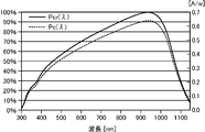
- FIG. 2 shows the relationship between the relative spectral sensitivity Pcr ( ⁇ ) and the absolute spectral sensitivity Pc ( ⁇ ).
- the spectral sensitivity P ( ⁇ ) of the solar cell 31 to be measured is expressed by the following formula (3).
- P ( ⁇ ) ⁇ Pc ( ⁇ ) / Pcm ( ⁇ ) ⁇ ⁇ Psm ( ⁇ ) (3)
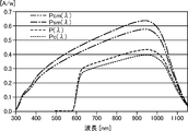
- FIG. 3 shows the relationship among the spectral sensitivity Pcm ( ⁇ ) and absolute spectral sensitivity Pc ( ⁇ ) of the reference cell 30, the spectral sensitivity Psm ( ⁇ ) of the solar cell 31 to be measured, and the spectral sensitivity P ( ⁇ ) after calibration. It is shown.
- the short-circuit current of solar cells calibrated in Japan is the short-circuit current in an engine in the United States. May not always match. That is, even if the same reference cell is used, the value of the short circuit current Isc measured by each engine differs from each other due to the difference in the evaluation method between the measurement institutions around the world. Need to be corrected.
- the solar cell evaluation apparatus 100 for each engine described above is adopted by using the calibration value for each engine. There is no need to correct this.
- This spectral irradiance measurement apparatus 10 includes a solar simulator (SS) 11 that irradiates a measurement target solar cell 31 with pseudo-sunlight, a spectral irradiance measurement unit 12, a spectral irradiance calibration calculation unit 13, an ammeter voltmeter 14, and light amount adjustment.
- SS solar simulator
- a calculation unit 15, an official measurement value storage unit 16, and an absolute spectral sensitivity calculation unit 17 are provided.
- SS11 is JIS (C8912) (JIS; Japanese Industrial It is an illumination light source that generates light (pseudo-sunlight) simulating reference sunlight defined in Standards (Japanese Industrial Standards) and irradiates the solar cell 31 to be measured.
- JIS Japanese Industrial It is an illumination light source that generates light (pseudo-sunlight) simulating reference sunlight defined in Standards (Japanese Industrial Standards) and irradiates the solar cell 31 to be measured.
- the ammeter 14 measures the current and voltage of the solar cell 31 to be measured by the irradiation light from SS11, and outputs a short circuit current Isc.
- the light amount adjustment calculation unit 15 uses the following equation (5) from the spectral irradiance L ( ⁇ ) of SS11 and the spectral sensitivity P ( ⁇ ) of the measurement target solar cell 31 to measure the solar cell 31 to be measured.
- SS11 can be adjusted more accurately by using values obtained by calibrating L ( ⁇ ) and P ( ⁇ ) by the spectral irradiance calibration calculation unit 13 and the spectral sensitivity calibration calculation unit 22. .
- the public measurement value storage unit 16 is a memory for storing S ( ⁇ ), Pcr ( ⁇ ), and Isc, similarly to the public value storage unit 24 of the spectral sensitivity measuring apparatus 20.
- the absolute spectral sensitivity calculation unit 17 is a means for calculating Pc ( ⁇ ) and storing the calculated Pc ( ⁇ ) in the same manner as the absolute spectral sensitivity calculation unit 25 of the spectral sensitivity measuring apparatus 20.
- the spectral irradiance measurement unit 12 is a device that measures the spectral Lm ( ⁇ ) of the light irradiated by SS11.
- the spectral irradiance measuring unit 12 is set at a position where the measurement target solar cell 31 is set, and the spectral irradiance Lm ( ⁇ ) is measured.
- an optical branching device such as a mirror is interposed in the optical path from the SS 11 to the measurement target solar cell 31 (not shown), and this light branching device branches a part of the light irradiated by the SS 11.
- the spectral irradiance measuring apparatus 10 may be configured to reflect (for example, pass 99%, reflect 1%) and enter the spectral irradiance measurement unit 12.
- the spectral irradiance calibration calculation unit 13 calibrates the spectral irradiance Lm ( ⁇ ) measured by the spectral irradiance measurement unit 12 and calculates the spectral irradiance L ( ⁇ ) that is the original spectral irradiance of the irradiation light of SS11. Means.
- Iscm short-circuit current [A] obtained by calculation at the time of measurement of the reference cell 30 with the SS 11 having the light amount adjusted
- the reference cell 30 is arranged under the illumination of SS11 of the solar cell evaluation device 100, and the short-circuit current measured by the ampere meter 14 is priced by a public institution.
- the light amount of SS11 is adjusted so as to obtain the short circuit current Isc. Since SS11 is adjusted in this way, the short-circuit current Isc obtained by the following equation (6) should match the short-circuit current defined by the public organization.
- Isc ⁇ Pc ( ⁇ ) ⁇ L ( ⁇ ) d ⁇ (6)
- the spectral irradiance measuring unit 12 which is a precision instrument may change in value due to dirt, vibration, etc. of the optical components with the usage time, and the measured spectral irradiance is not necessarily an absolute value.
- the spectral irradiance L ( ⁇ ) may not match.
- the short circuit current Iscm is expressed by the following equation (7).
- Iscm ⁇ Pc ( ⁇ ) ⁇ Lm ( ⁇ ) d ⁇ (7)
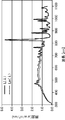
- FIG. 4 shows the relationship between the corrected spectral irradiance L ( ⁇ ) and the measured spectral irradiance Lm ( ⁇ ).
- Ks Isc / Iscm (10)
- the solar cell evaluation apparatus 100 having such a configuration can be configured using a computer such as a personal computer, for example, and executes the above-described spectral irradiance calibration calculation by executing software programmed with the spectral irradiance calibration calculation method.
- the unit 13 is functionally configured in the computer.
- the above-described spectral sensitivity calibration calculation unit 22 is functionally configured in a computer by executing software programmed with a spectral sensitivity calibration calculation method and the like.
- the computer includes not only the spectral irradiance calibration calculation unit 13 and the like, but also the short-circuit current calculation unit 15, the official measurement value storage unit 16, the absolute spectral sensitivity calculation unit 17, the spectral sensitivity storage unit 23, the public One or more of the target value storage unit 24 and the absolute spectral sensitivity calculation unit 25 may be configured, and the blocks of the respective units are functionally configured in the computer by executing software corresponding to the unit to be configured.
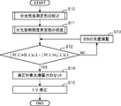
- FIG. 5 is a flowchart illustrating processing when the solar cell evaluation device 100 measures the short-circuit current of the solar cell 31 to be measured.
- step S10 first, calibration processing of the spectral sensitivity measuring unit 21 is performed, and the spectral sensitivity P ( ⁇ ) after calibration in the measurement target solar cell 31 is obtained (step S10).
- step S11 calibration processing of the spectral irradiance measuring unit 12 is performed, and the spectral irradiance L ( ⁇ ) after calibration when the reference cell 30 of the absolute spectral sensitivity Pc ( ⁇ ) is set is obtained (step S11).
- the light amount adjustment calculation unit 15 acquires the spectral sensitivity P ( ⁇ ) from the spectral sensitivity calibration calculation unit 22, acquires the spectral irradiance L ( ⁇ ) from the spectral irradiance calibration calculation unit 13, and the spectral irradiance of the reference sunlight.
- S ( ⁇ ) is read from the official measurement value storage unit 16.
- the light quantity adjustment calculation unit 15 creates the light quantity control signal CTL so that “ ⁇ P ( ⁇ ) ⁇ L ( ⁇ ) d ⁇ ” and “ ⁇ P ( ⁇ ) ⁇ S ( ⁇ ) d ⁇ ” are the same.
- Step S12 the light amount adjustment of SS11 is performed (Step S13).
- the adjusted spectral irradiance L ( ⁇ ) is optimum for the measurement of the solar cell 31 whose spectral sensitivity P ( ⁇ ) is to be measured. That is, the same short-circuit current that is generated when the measurement target solar cell 31 is irradiated with the reference sunlight can be measured.
- step S14 when the measurement target solar cell 31 whose spectral sensitivity P ( ⁇ ) has been measured in step S10 is set (step S14), the ampere meter 14 performs IV measurement and outputs a short-circuit current (step S14). S15).
- FIG. 6 is a flowchart of the calibration process of the spectral sensitivity measuring unit 21.
- the spectral sensitivity measuring unit 21 causes the spectral sensitivity Pcm ( ⁇ ) Is measured, and the measurement result is stored in the spectral sensitivity storage unit 23.
- the absolute spectral sensitivity Pc ( ⁇ ) is obtained and stored by the absolute spectral sensitivity calculator 25 (step S20). More specifically, the absolute spectral sensitivity calculation unit 25 receives the short-circuit current Isc of the reference cell, the spectral irradiance S ( ⁇ ) of the reference sunlight, and the relative spectral sensitivity of the reference cell from the public measurement value storage unit 24. Pcr ( ⁇ ) is read out, and the absolute spectral sensitivity Pc ( ⁇ ) is obtained and stored using equation (2).
- the spectral sensitivity measuring unit 21 measures the spectral sensitivity Psm ( ⁇ ).
- the spectral sensitivity calibration calculation unit 22 reads the absolute spectral sensitivity Pc ( ⁇ ) of the reference cell from the absolute spectral sensitivity calculation unit 25 and reads the spectral sensitivity Pcm ( ⁇ ) of the reference cell from the spectral sensitivity storage unit 23 to obtain the equation (3). Is used to obtain the corrected spectral sensitivity P ( ⁇ ) from the spectral sensitivity Psm ( ⁇ ) input from the spectral sensitivity measurement unit 21 (step S21).
- FIG. 7 is a flowchart of the calibration process of the spectral irradiance measurement unit 12.
- the absolute spectral sensitivity calculation unit 17 obtains and stores the absolute spectral sensitivity Pc ( ⁇ ). More specifically, the absolute spectral sensitivity calculation unit 17 receives the short-circuit current Isc of the reference cell, the spectral irradiance S ( ⁇ ) of the reference sunlight, and the relative spectral sensitivity of the reference cell from the public measurement value storage unit 16. Pcr ( ⁇ ) is read out, and the absolute spectral sensitivity Pc ( ⁇ ) is obtained and stored using equation (2).
- step S20 the light amount of SS11 is adjusted.
- the reference cell 30 is arranged under the SS 11 instead of the measurement target solar cell 31 of FIG.
- the light amount adjustment of SS11 is performed (step S32) so that the short-circuit current T and the short-circuit current Isc of the reference cell 30 measured by the public organization are the same (step S31).
- the spectral irradiance measuring unit 12 measures the spectral irradiance Lm ( ⁇ ) of SS11, and the spectral irradiance calibration calculating unit 13 obtains the short-circuit current Iscm of the reference cell 30 (step S21). (7)).
- the calibration coefficient Ks is obtained by the spectral irradiance calibration calculation unit 13 (step S22, equation (9)).
- the spectral irradiance L ( ⁇ ) is obtained by the spectral irradiance calibration calculation unit 13 (step S23, equation (10)).
- each of the spectral irradiance measuring apparatus 10 and the spectral sensitivity measuring apparatus 20 calculates the absolute spectral sensitivity Pc ( ⁇ ) of the reference cell. You may make it memorize
- FIG. 9A is a diagram illustrating a measurement result at the SS in which the light amount is adjusted without using the calibration method of the present embodiment
- FIG. 9B is a diagram illustrating the light amount using the calibration method of the present embodiment. It is a figure which shows the measurement result in SS which adjusted.
- These vertical axes represent measurement errors, and these horizontal axes represent the calculated short-circuit current Isc.
- PVM-589 is a crystalline Si type solar cell
- the measurement error is obtained as follows.
- the spectral irradiance of SS11 is L ( ⁇ ) and the spectral sensitivity of the solar cell 31 to be measured is P ( ⁇ )
- the calculated Isc which is the calculated short-circuit current
- the measurement error is obtained by the following equation (13).
- the measurement error of each solar cell is distributed in the range of ⁇ 0.79% to 1.84%.
- the measurement error is ⁇ 1.19%. It is within the range of ⁇ 1.42%.
- the average value of the distribution was changed from 0.4% to 0%.
- FIG. 10 shows an example in which an SS different from that shown in FIG. 9 is used.
- FIG. 10A is a diagram illustrating a measurement result at the SS in which the light amount adjustment is performed without using the calibration method of the present embodiment
- FIG. 10B is a diagram illustrating the light amount using the calibration method of the present embodiment. It is a figure which shows the measurement result in SS which adjusted.
- the measurement error of each solar cell is distributed in the range of ⁇ 3.42% to ⁇ 0.37%, but in FIG. 10B, the measurement error is ⁇ 2.24. It is within the range of% to 0.86%. The average value of the distribution was changed from ⁇ 1.85% to ⁇ 0.65%.
- the spectral sensitivity measuring unit that measures the spectral sensitivity of the solar cell that is the measurement target, the short-circuit current when the reference sunlight is irradiated, and the relative spectral sensitivity are measured in advance.
- a spectral sensitivity calibration calculation unit that calibrates the spectral sensitivity using a reference photovoltaic element.
- the reference photovoltaic element is preferably a reference cell for which the solar cell to be measured is priced, a pseudo reference cell having a spectral sensitivity that approximates the spectral sensitivity of the solar cell, or the like.
- a method for calibrating a spectral sensitivity measuring apparatus comprising: a spectral sensitivity measuring apparatus including a spectral sensitivity measuring section that measures the spectral sensitivity of a solar cell that is a measurement target. It is a sensitivity calibration method, and includes a step of calibrating the spectral sensitivity using a reference photovoltaic element in which the short-circuit current when the reference sunlight is irradiated and the relative spectral sensitivity is measured in advance.
- the spectral sensitivity measuring apparatus and the calibration method of such a configuration have a public organization relative to the measurement result in which an error has occurred due to aging degradation, that is, the spectral sensitivity of the solar cell to be measured measured by the spectral sensitivity measuring unit.
- Calibration can be performed using a reference solar cell that measures short-circuit current due to spectral sensitivity and spectral irradiance.
- the spectral sensitivity calibration calculation unit obtains an absolute spectral sensitivity of the reference photovoltaic element by using the following formula (C1), By using the formula (C2), the spectral sensitivity measured by the spectral sensitivity measuring unit is calibrated to calculate the spectral sensitivity after calibration.
- Pc ( ⁇ ) (Isc / ( ⁇ Pcr ( ⁇ ) ⁇ S ( ⁇ ) d ⁇ )) ⁇ Pcr ( ⁇ ) (C1)
- P ( ⁇ ) (Pc ( ⁇ ) / Pcm ( ⁇ )) ⁇ Psm ( ⁇ ) (C2)
- Pc ( ⁇ ) is the absolute spectral sensitivity of the reference photovoltaic element
- Isc is the short-circuit current due to the reference sunlight
- Pcr ( ⁇ ) is the relative spectral sensitivity
- S ( ⁇ ) is the spectral irradiance due to the reference sunlight
- P ( ⁇ ) is the spectral sensitivity after the calibration
- Pcm ( ⁇ ) is the reference photovoltaic power measured by the spectral sensitivity measuring unit.
- the spectral sensitivity of the element, and Psm ( ⁇ ) is the spectral sensitivity of the solar cell.
- the spectral sensitivity measuring apparatus having such a configuration can calibrate the spectral sensitivity Psm ( ⁇ ) of the solar cell to be measured, which is measured by the spectral sensitivity measuring unit, using the above formulas (C1) and (C2). .
- the solar cell evaluation apparatus measures the short circuit current of the solar cell by the solar simulator which irradiates a solar cell by using the light which imitated the standard sunlight of spectral irradiance as irradiation light, and the said irradiation light
- a spectral irradiation illuminance calibration calculation unit that calibrates the spectral irradiance using an element and obtains the spectral irradiation illuminance is provided.
- the spectral irradiance calibration method includes a solar simulator that irradiates a solar cell with light simulating the reference sunlight of spectral irradiance as irradiation light, and measures a short-circuit current of the solar cell by the irradiation light.
- a solar cell evaluation apparatus comprising a short-circuit current measuring unit and a spectral irradiance measuring unit for measuring the spectral irradiance of the solar simulator, the spectral irradiance calibration method for calibrating the spectral irradiance measuring unit, the reference It includes a step of calibrating the spectral irradiance and obtaining the spectral irradiation illuminance by using a reference photovoltaic device whose short-circuit current and the relative spectral sensitivity when sunlight is irradiated are measured in advance.
- the solar cell evaluation apparatus having such a configuration and the calibration method thereof have a measurement result in which an error has occurred due to aging degradation, i.e., the spectral irradiance of the solar simulator measured by the spectral irradiance measurement unit, and the public institution performs relative spectral analysis. Calibration is possible using a reference solar cell that measures the short-circuit current due to sensitivity and spectral irradiance.
- the following formula (Isc / ( ⁇ Pc ( ⁇ ) ⁇ Lm ( ⁇ ) d ⁇ )) ⁇ Lm ( ⁇ ) (C3)
- L ( ⁇ ) is the spectral irradiance after calibration
- Isc is the short-circuit current due to the reference sunlight
- Pc ( ⁇ ) is the absolute spectral sensitivity of the reference photovoltaic element.
- Lm ( ⁇ ) is the spectral irradiance measured by the spectral irradiance measurement unit.
- the spectral irradiance calibration calculation unit obtains the absolute spectral sensitivity of the reference photovoltaic element by using the following formula (C4).
- the spectral irradiance L ( ⁇ ) after calibration is calculated by calibrating the spectral irradiance measured by the spectral irradiance measuring unit.
- Pc ( ⁇ ) (Isc / ( ⁇ Pcr ( ⁇ ) ⁇ S ( ⁇ ) d ⁇ )) ⁇ Pcr ( ⁇ ) (C4)
- L ( ⁇ ) (Isc / ( ⁇ Pc ( ⁇ ) ⁇ Lm ( ⁇ ) d ⁇ )) ⁇ Lm ( ⁇ ) (C5)
- Pc ( ⁇ ) is the absolute spectral sensitivity of the reference photovoltaic element
- Isc is the short-circuit current due to the reference sunlight
- Pcr ( ⁇ ) is the relative spectral sensitivity
- S ( ⁇ ) is the spectral irradiance due to the reference sunlight
- L ( ⁇ ) is the spectral irradiance after calibration
- Lm ( ⁇ ) is the spectral irradiance measured by the spectral irradiance measurement unit. Irradiance.
- the solar cell evaluation apparatus having such a configuration can calibrate the spectral irradiance of the solar simulator measured by the spectral irradiance measurement unit by the above formulas (C4) and (C5).
- a spectral sensitivity measurement unit that measures spectral sensitivity of a solar cell that is a measurement target, and the reference photovoltaic element
- a spectral sensitivity calibration calculation unit that calibrates the spectral sensitivity and obtains the spectral sensitivity.
- the spectral irradiance measurement unit and the spectral sensitivity measurement unit are calibrated using the same reference photovoltaic element, the spectral irradiance and the spectral sensitivity of the solar cell to be measured are Higher-precision measurement is possible than the processing using.
- a spectral sensitivity measuring device a solar cell evaluation device, a spectral sensitivity calibration method, and a spectral irradiance calibration method can be provided.
Landscapes
- Photovoltaic Devices (AREA)
Abstract
本発明にかかる分光感度測定装置20および分光感度校正方法では、基準太陽光を照射した場合の短絡電流、および、相対分光感度が予め測定されている基準光起電力素子を用いて、測定対象である太陽電池31の分光感度が校正される。このため、本発明にかかる分光感度測定装置20および分光感度校正方法は、測定対象である太陽電池31の分光感度を校正することができる。また、本発明にかかる太陽電池評価装置100および分光放射照度校正方法では、基準太陽光を照射した場合の短絡電流、および、相対分光感度が予め測定されている基準光起電力素子を用いて、前記分光放射照度が校正される。このため、本発明にかかる太陽電池評価装置100および分光放射照度校正方法は、ソーラシミュレータの分光放射照度を校正することができる。
Description
本発明は、太陽電池を評価するための装置および方法に関する。
近年、太陽電池は、広く普及し、メーカ間あるいは製品間で激しく競争している。また、その組成も、単結晶シリコン、アモルファスシリコン、薄膜シリコンおよび有機化合物等の、多くの種類が開発されている。
このような太陽電池は、材料および構造に起因する固有の分光感度特性を有するので、その光電変換特性は、性能評価用の照射光の分光放射照度に大きく依存する。そこで、これらの太陽電池の光電変換効率を公正に評価するために、評価方法が、IEC60904(IEC;International Electrotechnical Commission;国際電気標準会議)やJISC8905~C8991(JIS;Japanese Industrial Standards;日本工業規格)で定義されている。太陽電池の性能測定は、国際的に協定された標準試験条件の下で、基準太陽光の分光放射照度(=S(λ))に近似させた分光放射照度L(λ)を持つソーラシミュレータを用いて屋内で実施されることが多い。
このソーラシミュレータには、その分光放射照度が基準太陽光と完全には一致していない場合や、メーカ間および同じメーカでも機差が存在している場合がある。このため、分光感度特性が同じ太陽電池であっても、異なるソーラシミュレータで太陽電池を測定すると、太陽電池の発電量が異なってしまう。
そこで、測定者は、例えば、産業技術総合技術研究所(=日本国において、国際的に統一された基準太陽光スペクトル等を持っている国立またはそれに準じる機関)に、サンプルとなる太陽電池を送付してその測定を依頼する。それに応じてこれらの機関は、所有している限りなく基準太陽光に近い高近似ソーラシミュレータを用いてサンプルの自然太陽光AM1.5、100mW/cm2における短絡電流Iscを求め、測定値(=A)を記載して依頼者である前記測定者に返送する。
そして、これを受けて測定者は、返送されて来たサンプルを、以降、自社の基準セルとして、ソーラシミュレータの光量調整用に使用している。すなわち、測定者は、ソーラシミュレータの照射光を基準セルに照射し、その短絡電流Iscが前記測定値Aとなるように、ソーラシミュレータの光量を調整する。そして、測定者は、実際に測定すべき(検査対象の製品の)太陽電池の特性を測定している。前述のように基準太陽光の分光スペクトルを厳密に再現することは、困難であるが、これは、可能な限り、各社のソーラシミュレータをそれに合せ込むための手法である。
ところが、上述の手法では、基準セルによる校正が完了するまでに、測定者がサンプルを作成して郵送し、公的機関がサンプルを測定して返送することが必要であり、このため、時間および費用が掛かってしまう。しかも、校正は、一度だけ行えば済むものではなく、測定すべき太陽電池の分光感度が変わる都度、新たに基準セルを作成して校正をやり直す必要があり、前記時間および費用は、膨大なものになる。
そこで、測定対象の太陽電池の分光感度P(λ)を予め測定しておくことによって、分光放射照度S(λ)での基準太陽光による発電電力ESを、次式(P1)を用いることによって換算する太陽電池の評価方法が提案されている(特許文献1等参照)。
ES=EL・{∫S(λ)・P(λ)dλ}/{∫L(λ)・P(λ)dλ} ・・・(P1)
ここで、ELは、分光放射照度L(λ)のソーラシミュレータでの照射光による発電電力である。
ES=EL・{∫S(λ)・P(λ)dλ}/{∫L(λ)・P(λ)dλ} ・・・(P1)
ここで、ELは、分光放射照度L(λ)のソーラシミュレータでの照射光による発電電力である。
しかしながら、上述の手法では、測定対象の太陽電池の分光感度P(λ)およびソーラシミュレータの分光放射照度L(λ)が正確であることが前提となるが、これら測定値に誤差が生じてくる場合がある。すなわち、測定対象の太陽電池の分光感度P(λ)を測定する装置またはソーラシミュレータの分光放射照度L(λ)を測定する装置に経時変化が起こる等した場合である。これら測定値が変化してしまうと、正確な短絡電流を計算で求めることができなくなってしまう。
本発明は、上述の事情に鑑みて為された発明であり、その目的は、太陽電池を評価する場合に、測定対象である太陽電池の分光感度を測定する分光感度測定装置を校正すること、および、ソーラシミュレータの分光放射照度を測定する分光放射照度測定装置を校正することである。
本発明にかかる分光感度測定装置および分光感度校正方法では、基準太陽光を照射した場合の短絡電流、および、相対分光感度が予め測定されている基準光起電力素子を用いて、測定対象である太陽電池の分光感度が校正される。このため、本発明にかかる分光感度測定装置および分光感度校正方法は、測定対象である太陽電池の分光感度を校正することができる。
また、本発明にかかる太陽電池評価装置および分光放射照度校正方法では、基準太陽光を照射した場合の短絡電流、および、相対分光感度が予め測定されている基準光起電力素子を用いて、前記分光放射照度が校正される。このため、本発明にかかる太陽電池評価装置および分光放射照度校正方法は、ソーラシミュレータの分光放射照度を校正することができる。
上記並びにその他の本発明の目的、特徴および利点は、以下の詳細な記載と添付図面から明らかになるであろう。
以下、本発明にかかる実施の一形態を図面に基づいて説明する。なお、各図において同一の符号を付した構成は、同一の構成であることを示し、適宜、その説明を省略する。また、本明細書において、総称する場合には添え字を省略した参照符号で示し、個別の構成を指す場合には添え字を付した参照符号で示す。
<実施形態>
本実施形態は、ソーラシミュレータ(以下、「SS」という場合がある。)の分光放射照度を測定する分光放射照度測定部、および、測定対象である太陽電池(以下、「測定対象太陽電池」という。)の分光感度を測定する分光感度測定部を校正するものである。したがって、実施の一形態として、SSの分光放射照度と測定対象太陽電池の分光感度とを用いてSSの光量調整を行う太陽電池評価装置を例に以下に説明する。
本実施形態は、ソーラシミュレータ(以下、「SS」という場合がある。)の分光放射照度を測定する分光放射照度測定部、および、測定対象である太陽電池(以下、「測定対象太陽電池」という。)の分光感度を測定する分光感度測定部を校正するものである。したがって、実施の一形態として、SSの分光放射照度と測定対象太陽電池の分光感度とを用いてSSの光量調整を行う太陽電池評価装置を例に以下に説明する。
本実施形態の太陽電池評価装置では、測定対象太陽電池の分光感度P(λ)が予め測定されており、光量調整の際には、SSの分光放射照度L(λ)が測定され、これらを基に光量制御信号CTLが作成され、SSの光量調整が行われる(詳細は、後述する)。
したがって、より正確にSSを調整するためには、測定対象太陽電池の分光感度P(λ)と、SSの分光放射照度L(λ)がより正確に測定されることが必要となる。
本実施形態では、測定対象太陽電池の評価を開始する前に、SSの分光放射照度L(λ)を測定する分光放射照度測定部と、測定対象の太陽電池の分光感度P(λ)を測定する分光感度測定部とを校正することによって、より正確な光量調整が行われる。
この分光放射照度測定部と分光感度測定部との校正には、産業技術総合技術研究所等の公的機関による値付けされた基準セルの短絡電流Iscと相対分光感度Pcr(λ)または絶対分光感度Pc(λ)とが用いられる。分光放射照度測定部および分光感度測定部の校正には、それぞれ異なる基準セルが用いられてもよいが、校正精度を向上させるためには、同じ基準セルを用いる方が望ましい。
以下、本発明にかかる実施の一形態を図面に基づいて説明する。図1は、実施形態にかかる太陽電池評価装置100の構成を示すブロック図である。この太陽電池評価装置100は、分光放射照度測定装置10および分光感度測定装置20を備えている。
<分光感度測定装置>
まず、分光感度測定装置20の構成を説明する。この分光感度測定装置20は、分光感度測定部21、分光感度校正演算部22、分光感度記憶部23、公的測定値記憶部24、および、絶対分光感度演算部25を備える。
まず、分光感度測定装置20の構成を説明する。この分光感度測定装置20は、分光感度測定部21、分光感度校正演算部22、分光感度記憶部23、公的測定値記憶部24、および、絶対分光感度演算部25を備える。
分光感度測定部21は、測定対象太陽電池31の分光感度Psm(λ)を測定する装置である。
分光感度校正演算部22は、分光感度測定部21で測定した測定対象太陽電池31の分光感度Psm(λ)を校正し、測定対象太陽電池31の本来の分光感度である分光感度P(λ)を算出する演算手段である。この校正には、基準セル30の絶対分光感度Pc(λ)と、分光感度測定部21で測定した基準セル30の分光感度Pcm(λ)とが用いられる。
分光感度記憶部23は、分光感度測定部21で測定した基準セル30の分光感度Pcm(λ)を記憶しておくメモリである。
公的測定値記憶部24は、基準太陽光の分光放射照度S(λ)、および、公的機関による基準セル30の測定結果を記憶しておくメモリである。基準セル30の測定結果とは、基準セルの相対分光感度Pcr(λ)、および、分光放射照度S(λ)の照射光による基準セルの短絡電流Iscである。
絶対分光感度演算部25は、基準セル30の絶対分光感度Pc(λ)を算出し、算出した絶対分光感度Pc(λ)を記憶しておく手段である。
以下、基準セル30の絶対分光感度Pc(λ)の求め方を説明する。
まず、説明に用いる変数の定義の一覧を示す。
Pcr(λ):公的機関で値付けされた基準セル30の相対分光感度[%]
Pc(λ):基準セル30の絶対分光感度[A/W/m2/nm]
Pcm(λ):公的機関で値付けされた基準セル30を、分光感度測定装置20の分光感度測定部21で測定した分光感度[A/W/m2/nm]
Psm(λ):測定対象太陽電池31を分光感度測定装置20の分光感度測定部21で測定した分光感度[A/W/m2/nm]
P(λ):測定対象太陽電池31の分光感度[A/W/m2/nm]
Isc:公的機関で値付けされた基準セル30の短絡電流[A]
S(λ):基準太陽光の分光放射照度[W/m2/nm]
Kp:変換係数[W/m2/nm/%]
Pcr(λ):公的機関で値付けされた基準セル30の相対分光感度[%]
Pc(λ):基準セル30の絶対分光感度[A/W/m2/nm]
Pcm(λ):公的機関で値付けされた基準セル30を、分光感度測定装置20の分光感度測定部21で測定した分光感度[A/W/m2/nm]
Psm(λ):測定対象太陽電池31を分光感度測定装置20の分光感度測定部21で測定した分光感度[A/W/m2/nm]
P(λ):測定対象太陽電池31の分光感度[A/W/m2/nm]
Isc:公的機関で値付けされた基準セル30の短絡電流[A]
S(λ):基準太陽光の分光放射照度[W/m2/nm]
Kp:変換係数[W/m2/nm/%]
基準セル30の短絡電流Iscは、次式(1)に示すように、Pcr(λ)とS(λ)の積分値に、変換係数(=Kp)を掛けた値となる。
Isc=Kp・∫Pcr(λ)・S(λ)dλ ・・・(1)
ここで、Kp=Isc/{∫Pcr(λ)・S(λ)dλ}である。したがって、絶対分光感度Pc(λ)は、次式(2)によって求められる。
Pc(λ)=Kp・Pcr(λ)
={Isc/(∫Pcr(λ)・S(λ)dλ)}・Pcr(λ) ・・・(2)
図2には、これら相対分光感度Pcr(λ)と絶対分光感度Pc(λ)との関係が示されている。
Isc=Kp・∫Pcr(λ)・S(λ)dλ ・・・(1)
ここで、Kp=Isc/{∫Pcr(λ)・S(λ)dλ}である。したがって、絶対分光感度Pc(λ)は、次式(2)によって求められる。
Pc(λ)=Kp・Pcr(λ)
={Isc/(∫Pcr(λ)・S(λ)dλ)}・Pcr(λ) ・・・(2)
図2には、これら相対分光感度Pcr(λ)と絶対分光感度Pc(λ)との関係が示されている。
次に、測定対象太陽電池31の分光感度Psm(λ)の校正の方法について説明する。
分光感度測定部21が経年変化等による誤差がなければ、Pc(λ)とPcm(λ)は、波長に関係なく同一となるが、実際には、精密機器である分光感度測定部は、何らかの誤差が生じる可能性があるので、この波長毎の補正係数として、(Pc(λ)/Pcm(λ))が求められ、この補正係数を用いて、測定対象太陽電池31の分光感度であるPsm(λ)を乗算することで、P(λ)が求められる。
測定対象太陽電池31の分光感度P(λ)は、次式(3)となる。
P(λ)={Pc(λ)/Pcm(λ)}・Psm(λ) ・・・(3)
図3には、基準セル30の分光感度Pcm(λ)および絶対分光感度Pc(λ)、測定対象太陽電池31の分光感度Psm(λ)および校正後の分光感度P(λ)との関係が示されている。
P(λ)={Pc(λ)/Pcm(λ)}・Psm(λ) ・・・(3)
図3には、基準セル30の分光感度Pcm(λ)および絶対分光感度Pc(λ)、測定対象太陽電池31の分光感度Psm(λ)および校正後の分光感度P(λ)との関係が示されている。
なお、校正方法の異なる主要4カ国(日米独中)の1次基準太陽電池の誤差量が±2%あり、日本で校正された太陽電池の短絡電流は、米国での機関での短絡電流と必ずしも一致しない場合もある。すなわち、同じ基準セルを使用しても、世界の測定機関間での評価方法の違いにより、各機関が測定した短絡電流Iscの値が相互に異なってしまい、機関毎にその太陽電池評価装置100を補正する必要がある。しかし、本実施形態によれば、分光感度、短絡電流は、各校正機関毎の校正値を使用しているので、機関毎の校正値を採用することで前述の機関毎に太陽電池評価装置100を補正する必要がないことになる。
<分光放射照度測定装置>
次に、分光放射照度測定装置10の構成について説明する。この分光放射照度測定装置10は、測定対象太陽電池31に疑似太陽光を照射するソーラシミュレータ(SS)11、分光放射照度測定部12、分光放射照度校正演算部13、電流電圧計14、光量調整演算部15、公的測定値記憶部16、および、絶対分光感度演算部17を備えている。
次に、分光放射照度測定装置10の構成について説明する。この分光放射照度測定装置10は、測定対象太陽電池31に疑似太陽光を照射するソーラシミュレータ(SS)11、分光放射照度測定部12、分光放射照度校正演算部13、電流電圧計14、光量調整演算部15、公的測定値記憶部16、および、絶対分光感度演算部17を備えている。
SS11は、JIS(C8912)(JIS;Japanese Industrial
Standards;日本工業規格)で定義されている基準太陽光を模した光(疑似太陽光)を発生し、測定対象太陽電池31に照射する照明光源である。
Standards;日本工業規格)で定義されている基準太陽光を模した光(疑似太陽光)を発生し、測定対象太陽電池31に照射する照明光源である。
電流電圧計14は、SS11からの照射光による測定対象太陽電池31の電流および電圧を測定し、短絡電流Iscを出力する。
光量調整演算部15は、分光感度測定装置20で測定した測定対象太陽電池31の分光感度P(λ)と、公的測定値記憶部16に記憶されている基準太陽光の分光放射照度S(λ)とから、次式(4)を用いて、測定対象太陽電池31の理論上の短絡電流Iscrefを算出する。
Iscref=∫P(λ)・S(λ)dλ ・・・(4)
Iscref=∫P(λ)・S(λ)dλ ・・・(4)
次に、光量調整演算部15は、SS11の分光放射照度L(λ)と、測定対象太陽電池31の分光感度P(λ)とから、次式(5)を用いて、測定対象太陽電池31の短絡電流Iscを算出する。
Isc=∫P(λ)・L(λ)dλ ・・・(5)
Isc=∫P(λ)・L(λ)dλ ・・・(5)
光量調整演算部15は、Isc=Iscrefとなるように、光量制御信号CTLを作成し、SS11の光量調整を行う。
この場合、L(λ)およびP(λ)を、分光放射照度校正演算部13および分光感度校正演算部22で校正した値を用いることで、より正確なSS11の調整を行うことが可能となる。
次に、公的測定値記憶部16は、分光感度測定装置20の公的値記憶部24と同様に、S(λ)、Pcr(λ)およびIscを記憶しておくメモリである。
絶対分光感度演算部17は、分光感度測定装置20の絶対分光感度演算部25と同様に、Pc(λ)を算出し、算出したPc(λ)を記憶しておく手段である。
次に、分光放射照度測定部12は、SS11による照射光の分光的Lm(λ)を測定する装置である。
測定対象太陽電池31をセットする位置に分光放射照度測定部12がセットされ、分光放射照度Lm(λ)が測定される。または、例えば、SS11から測定対象太陽電池31への光路に例えばミラー等の光分岐器が介在され(図示していない)、この光分岐器によって、SS11による照射光の一部の光を分岐させて、例えば反射(たとえば99%を通過、1%を反射)させて分光放射照度測定部12に入射させるように、分光放射照度測定装置10が構成されてもよい。
分光放射照度校正演算部13は、分光放射照度測定部12で測定した分光放射照度Lm(λ)を校正し、SS11の照射光本来の分光放射照度である分光放射照度L(λ)を求める演算手段である。
ここで、分光放射照度の校正の方法について説明する。
説明に用いる変数の定義の一覧を示す。
L(λ):SS11の絶対分光放射照度[W/m2/nm]
Lm(λ):SS11を分光放射照度測定装置10の分光放射照度測定部12で測定した分光放射照度[W/m2/nm]
Iscm:基準セル30を光量調整済のSS11で測定時の計算で求めた短絡電流[A]
L(λ):SS11の絶対分光放射照度[W/m2/nm]
Lm(λ):SS11を分光放射照度測定装置10の分光放射照度測定部12で測定した分光放射照度[W/m2/nm]
Iscm:基準セル30を光量調整済のSS11で測定時の計算で求めた短絡電流[A]
まず、図1に示す測定対象太陽電池31に代えて基準セル30が太陽電池評価装置100のSS11の照明下に配置され、電流電圧計14で測定される短絡電流が、公的機関で値付けされた短絡電流IscになるようにSS11の光量が調整される。このようにSS11を調整しているので、次式(6)で求めた短絡電流Iscは、公的機関で定義された短絡電流と一致するはずである。
Isc=∫Pc(λ)・L(λ)dλ ・・・(6)
Isc=∫Pc(λ)・L(λ)dλ ・・・(6)
しかしながら、実際には、精密機器である分光放射照度測定部12は、使用時間とともに、光学部品の汚れ、振動等により、値が変化することがあり、測定された分光放射照度は、必ずしも絶対値分光放射照度L(λ)と一致しない場合がある。
そこで、この不一致を補正するために分光放射照度測定部12の校正が必要となる。
SS11の光量調整後、短絡電流Iscmは、次式(7)となる。
Iscm=∫Pc(λ)・Lm(λ)dλ ・・・(7)
Iscm=∫Pc(λ)・Lm(λ)dλ ・・・(7)
ここで、分光放射照度の時間とともに変化する量に波長依存性がないと仮定する。図4には、校正後の分光放射照度L(λ)と測定された分光放射照度をLm(λ)との関係が示されている。
校正係数をKsとすると、次式(8)が成り立つ。
L(λ)=Ks・Lm(λ) ・・・(8)
上記式(6)、式(7)、式(8)より、次式(9)となるので、次式(10)から、SS11の絶対分光放射照度L(λ)は、次式(11)によって求めることができる。
Isc=Ks・∫Pc(λ)・Lm(λ)dλ
=Ks・Iscm ・・・(9)
Ks=Isc/Iscm ・・・(10)
L(λ)=Isc/Iscm・Lm(λ)
=[Isc/{∫Pc(λ)・Lm(λ)dλ}]・Lm(λ) ・・・(11)
L(λ)=Ks・Lm(λ) ・・・(8)
上記式(6)、式(7)、式(8)より、次式(9)となるので、次式(10)から、SS11の絶対分光放射照度L(λ)は、次式(11)によって求めることができる。
Isc=Ks・∫Pc(λ)・Lm(λ)dλ
=Ks・Iscm ・・・(9)
Ks=Isc/Iscm ・・・(10)
L(λ)=Isc/Iscm・Lm(λ)
=[Isc/{∫Pc(λ)・Lm(λ)dλ}]・Lm(λ) ・・・(11)
このような構成の太陽電池評価装置100は、例えば、パーソナルコンピュータ等のコンピュータを用いて構成可能であり、分光放射照度校正演算方法をプログラムしたソフトウェアを実行することによって、上述する分光放射照度校正演算部13がコンピュータに機能的に構成される。また、分光感度校正演算方法等をプログラムしたソフトウェアを実行することによって上述の分光感度校正演算部22がコンピュータに機能的に構成される。なお、コンピュータには、分光放射照度校正演算部13等だけではなく、図1に示す短絡電流演算部15、公的測定値記憶部16、絶対分光感度演算部17、分光感度記憶部23、公的値記憶部24および絶対分光感度演算部25のうちの1または複数が構成されてもよく、構成すべき部に相当するソフトウェアを実行することによって前記各部のブロックがコンピュータに機能的に構成される。
<動作>
次に、図5ないし図8を用いて、太陽電池評価装置100の動作について説明する。図5は、太陽電池評価装置100が、測定対象太陽電池31の短絡電流を測定する場合の処理を示すフローチャートである。
次に、図5ないし図8を用いて、太陽電池評価装置100の動作について説明する。図5は、太陽電池評価装置100が、測定対象太陽電池31の短絡電流を測定する場合の処理を示すフローチャートである。
図5において、まず、分光感度測定部21の校正処理が行われ、測定対象太陽電池31における校正後の分光感度P(λ)が求められる(ステップS10)。
次に、分光放射照度測定部12の校正処理が行われ、絶対分光感度Pc(λ)の基準セル30のセット時における校正後の分光放射照度L(λ)が求められる(ステップS11)。
光量調整演算部15は、分光感度P(λ)を分光感度校正演算部22から取得し、分光放射照度L(λ)を分光放射照度校正演算部13から取得し、基準太陽光の分光放射照度S(λ)を公的測定値記憶部16から読み出す。
そして、光量調整演算部15は、「∫P(λ)・L(λ)dλ」と「∫P(λ)・S(λ)dλ」とが同じになるように光量制御信号CTLを作成し(ステップS12)、SS11の光量調整を行う(ステップS13)。調整後の分光放射照度L(λ)は、分光感度P(λ)の測定対象太陽電池31の測定に最適なものである。すなわち、測定対象太陽電池31が基準太陽光を照射された時に発生するのと同じ短絡電流が測定できる。
その後、ステップS10で分光感度P(λ)が測定された測定対象太陽電池31がセットされると(ステップS14)、電流電圧計14は、I-V測定を行い、短絡電流を出力する(ステップS15)。
<分光感度測定部21の校正>
図6は、分光感度測定部21の校正処理のフローチャートである。分光感度測定部20の校正処理では、まず、分光感度測定装置20において、図1の測定対象太陽電池31に代えて基準セル30がセットされると、分光感度測定部21によって分光感度Pcm(λ)が測定され、測定結果が分光感度記憶部23に記憶される。
図6は、分光感度測定部21の校正処理のフローチャートである。分光感度測定部20の校正処理では、まず、分光感度測定装置20において、図1の測定対象太陽電池31に代えて基準セル30がセットされると、分光感度測定部21によって分光感度Pcm(λ)が測定され、測定結果が分光感度記憶部23に記憶される。
次に、絶対分光感度演算部25によって、絶対分光感度Pc(λ)が求められて記憶される(ステップS20)。より具体的には、絶対分光感度演算部25は、公的測定値記憶部24から、基準セルの短絡電流Isc、基準太陽光の分光放射照度S(λ)、および、基準セルの相対分光感度Pcr(λ)を読み出して、式(2)を用いて、絶対分光感度Pc(λ)を求めて記憶する。
次に、図1に示すように、測定対象太陽電池31が分光感度測定装置20にセットされると、分光感度測定部21によって分光感度Psm(λ)が測定される。
分光感度校正演算部22は、絶対分光感度演算部25から基準セルの絶対分光感度Pc(λ)読み出し、分光感度記憶部23から基準セルの分光感度Pcm(λ)を読み出して、式(3)を用いて、分光感度測定部21から入力された分光感度Psm(λ)から、校正後の分光感度P(λ)を求める(ステップS21)。
<分光放射照度測定部12の校正>
図7は、分光放射照度測定部12の校正処理のフローチャートである。分光放射照度測定部12の校正処理では、まず、絶対分光感度演算部17によって、絶対分光感度Pc(λ)が求められて記憶される。より具体的には、絶対分光感度演算部17は、公的測定値記憶部16から、基準セルの短絡電流Isc、基準太陽光の分光放射照度S(λ)、および、基準セルの相対分光感度Pcr(λ)を読み出して、式(2)を用いて、絶対分光感度Pc(λ)を求めて記憶する。
図7は、分光放射照度測定部12の校正処理のフローチャートである。分光放射照度測定部12の校正処理では、まず、絶対分光感度演算部17によって、絶対分光感度Pc(λ)が求められて記憶される。より具体的には、絶対分光感度演算部17は、公的測定値記憶部16から、基準セルの短絡電流Isc、基準太陽光の分光放射照度S(λ)、および、基準セルの相対分光感度Pcr(λ)を読み出して、式(2)を用いて、絶対分光感度Pc(λ)を求めて記憶する。
次に、SS11の光量調整を行う(ステップS20)。この光量調整は、図8のフローチャートで示すように、まず、図1の測定対象太陽電池31に代えて基準セル30がSS11の下に配置され(ステップS30)、電流電圧計14から出力される短絡電流Tと公的機関が測定した基準セル30の短絡電流Iscとが、同一になるように(ステップS31)、SS11の光量調整が行われる(ステップS32)。
SS11の光量調整が終わると、分光放射照度測定部12によってSS11の分光放射照度Lm(λ)が測定され、分光放射照度校正演算部13によって、基準セル30の短絡電流Iscmが求められる(ステップS21、式(7))。
次に、分光放射照度校正演算部13によって、校正係数Ksが求められる(ステップS22、式(9))。
次に、分光放射照度校正演算部13によって、分光放射照度L(λ)が求められる(ステップS23、式(10))。
本実施形態では、分光放射照度測定装置10および分光感度測定装置20のそれぞれで、基準セルの絶対分光感度Pc(λ)を求めることとしているが、どちらかの装置で求めたものをもう一方の装置に記憶させてもよく、また、これら装置以外の装置で予め求めたものをそれぞれの装置に記憶させることとしてもよい。
図9および図10に、図1の太陽電池評価装置100でSS11の光量調整を行った場合の、測定対象太陽電池31の評価結果を示す。図9(A)は、本実施形態の校正方法を用いないで光量調整を行ったSSでの測定結果を示す図であり、図9(B)は、本実施形態の校正方法を用いて光量調整を行ったSSでの測定結果を示す図である。これらの縦軸は、測定誤差を表し、これらの横軸は、計算上の短絡電流Iscを表す。また、「PVM-589」は、結晶Si型の太陽電池であり、「Y-44+HAF」、「R-65+HAF」、「B-440」、「R-60」、「R-60+HAF」、「B-390」および「G-530」は、それぞれ透過率が異なる光学フィルタをPVM-589に付加した太陽電池である。後述の図10も同様である。
測定誤差は、以下のように求める。SS11の分光放射照度をL(λ)、測定対象太陽電池31の分光感度をP(λ)とすると、計算された短絡電流である計算Iscは、次式(12)で求められる。電流電圧計14で測定した短絡電流を実測Iscとすると、測定誤差は、次式(13)で求められる。
計算Isc=∫P(λ)・L(λ)dλ ・・・(12)
測定誤差Isc(%)=計算Isc/実測Isc ・・・(13)
計算Isc=∫P(λ)・L(λ)dλ ・・・(12)
測定誤差Isc(%)=計算Isc/実測Isc ・・・(13)
図9(A)では、各太陽電池の測定誤差が、-0.79%~1.84%の範囲に分布しているが、図9(B)では、測定誤差が、-1.19%~1.42%の範囲内に収まっている。また、分布の平均値は、0.4%から0%になった。このように、分光放射照度測定部12と分光感度測定部21とを校正することで、光量調整したSSの分光放射照度がS(λ)により近くなったことがわかる。
図10は、図9とは異なるSSを用いた場合の例である。図10(A)は、本実施形態の校正方法を用いないで光量調整を行ったSSでの測定結果を示す図であり、図10(B)は、本実施形態の校正方法を用いて光量調整を行ったSSでの測定結果を示す図である。
図10(A)では、各太陽電池の測定誤差が、-3.42%~-0.37%の範囲に分布しているが、図10(B)では、測定誤差が、-2.24%~0.86%の範囲内に収まっている。また、分布の平均値は、-1.85%から-0.65%になった。
本明細書は、上記のように様々な態様の技術を開示しているが、そのうち主な技術を以下に纏める。
一態様にかかる分光感度測定装置は、測定対象である太陽電池の分光感度を測定する分光感度測定部と、基準太陽光を照射した場合の短絡電流、および、相対分光感度が予め測定されている基準光起電力素子を用いて、前記分光感度を校正する分光感度校正演算部とを備える。なお、基準光起電力素子は、好ましくは、測定対象となる太陽電池を値付けした基準セルや、太陽電池が持つ分光感度に近似する分光感度を持つ疑似基準セル等である。
また、他の一態様にかかる分光感度測定装置の校正方法は、測定対象である太陽電池の分光感度を測定する分光感度測定部を備える分光感度測定装置の、前記分光感度測定部を校正する分光感度校正方法であって、基準太陽光を照射した場合の短絡電流、および、相対分光感度が予め測定されている基準光起電力素子を用いて、前記分光感度を校正する工程を含む。
このような構成の分光感度測定装置およびその校正方法は、経年劣化等により誤差が生じた測定結果、すなわち、分光感度測定部が測定した測定対象の太陽電池の分光感度を、公的機関が相対分光感度および分光放射照度による短絡電流を測定した基準太陽電池を用いて、校正することが可能となる。
また、他の一態様では、上述の分光感度測定装置において、好ましくは、前記分光感度校正演算部は、下記式(C1)を用いることによって前記基準光起電力素子の絶対分光感度を求め、下記式(C2)を用いることによって、前記分光感度測定部で測定した分光感度を校正することで、校正後の分光感度を算出する。
Pc(λ)=(Isc/(∫Pcr(λ)・S(λ)dλ))・Pcr(λ) ・・・(C1)
P(λ)=(Pc(λ)/Pcm(λ))・Psm(λ) ・・・(C2)
ただし、Pc(λ)は、前記基準光起電力素子の絶対分光感度であり、Iscは、前記基準太陽光による前記短絡電流であり、Pcr(λ)は、前記相対分光感度であり、S(λ)は、前記基準太陽光による分光放射照度であり、P(λ)は、前記校正後の前記分光感度であり、Pcm(λ)は、前記分光感度測定部で測定した前記基準光起電力素子の分光感度であり、そして、Psm(λ)は、前記太陽電池の分光感度である。
Pc(λ)=(Isc/(∫Pcr(λ)・S(λ)dλ))・Pcr(λ) ・・・(C1)
P(λ)=(Pc(λ)/Pcm(λ))・Psm(λ) ・・・(C2)
ただし、Pc(λ)は、前記基準光起電力素子の絶対分光感度であり、Iscは、前記基準太陽光による前記短絡電流であり、Pcr(λ)は、前記相対分光感度であり、S(λ)は、前記基準太陽光による分光放射照度であり、P(λ)は、前記校正後の前記分光感度であり、Pcm(λ)は、前記分光感度測定部で測定した前記基準光起電力素子の分光感度であり、そして、Psm(λ)は、前記太陽電池の分光感度である。
このような構成の分光感度測定装置は、上記式(C1)および式(C2)によって、分光感度測定部が測定した測定対象の太陽電池の分光感度Psm(λ)を校正することが可能となる。
また、他の一態様にかかる太陽電池評価装置は、分光放射照度の基準太陽光を模した光を照射光として太陽電池に照射するソーラシミュレータと、前記照射光による太陽電池の短絡電流を測定する短絡電流測定部と、前記ソーラシュミレータの分光放射照度を測定する分光放射照度測定部と、前記基準太陽光を照射した場合の短絡電流、および、相対分光感度が予め測定されている基準光起電力素子を用いて、前記分光放射照度を校正し、分光照射照度を求める分光照射照度校正演算部とを備える。
また、他の一態様にかかる分光放射照度校正方法は、分光放射照度の基準太陽光を模した光を照射光として太陽電池に照射するソーラシミュレータと、前記照射光による太陽電池の短絡電流を測定する短絡電流測定部と、前記ソーラシュミレータの分光放射照度を測定する分光放射照度測定部とを備える太陽電池評価装置の、分光放射照度測定部を校正する分光放射照度校正方法であって、前記基準太陽光を照射した場合の短絡電流、および、相対分光感度が予め測定されている基準光起電力素子を用いて、前記分光放射照度を校正し、分光照射照度を求める工程を含む。
このような構成の太陽電池評価装置およびその校正方法は、経年劣化等により誤差が生じた測定結果、すなわち、分光放射照度測定部が測定したソーラシミュレータの分光放射照度を、公的機関が相対分光感度および分光放射照度による短絡電流を測定した基準太陽電池を用いて、校正することが可能となる。
また、他の一態様では、上述の太陽電池評価装置において、好ましくは、前記基準光起電力素子の絶対分光感度、および、前記分光放射照度測定部で測定した分光放射照度に基づき、下記式(C3)を用いることによって前記校正後の前記分光照射照度を算出する。
L(λ)=(Isc/(∫Pc(λ)・Lm(λ)dλ))・Lm(λ) ・・・(C3)
ただし、L(λ)は、前記校正後の前記分光照射照度であり、Iscは、前記基準太陽光による前記短絡電流であり、Pc(λ)は、前記基準光起電力素子の絶対分光感度であり、そして、Lm(λ)は、前記分光放射照度測定部で測定した分光放射照度である。
L(λ)=(Isc/(∫Pc(λ)・Lm(λ)dλ))・Lm(λ) ・・・(C3)
ただし、L(λ)は、前記校正後の前記分光照射照度であり、Iscは、前記基準太陽光による前記短絡電流であり、Pc(λ)は、前記基準光起電力素子の絶対分光感度であり、そして、Lm(λ)は、前記分光放射照度測定部で測定した分光放射照度である。
また、他の一態様では、上述の太陽電池評価装置において、好ましくは、前記分光放射照度校正演算部は、下記式(C4)を用いることによって、前記基準光起電力素子の絶対分光感度を求め、下記式(C5)を用いることによって、前記分光放射照度測定部で測定した分光放射照度を校正することで、校正後の分光放射照度L(λ)を算出する。
Pc(λ)=(Isc/(∫Pcr(λ)・S(λ)dλ))・Pcr(λ) ・・・(C4)
L(λ)=(Isc/(∫Pc(λ)・Lm(λ)dλ))・Lm(λ) ・・・(C5)
ただし、Pc(λ)は、前記基準光起電力素子の絶対分光感度であり、Iscは、前記基準太陽光による前記短絡電流であり、Pcr(λ)は、前記相対分光感度であり、S(λ)は、前記基準太陽光による分光放射照度であり、L(λ)は、前記校正後の前記分光照射照度であり、そして、Lm(λ)は、前記分光放射照度測定部で測定した分光放射照度である。
Pc(λ)=(Isc/(∫Pcr(λ)・S(λ)dλ))・Pcr(λ) ・・・(C4)
L(λ)=(Isc/(∫Pc(λ)・Lm(λ)dλ))・Lm(λ) ・・・(C5)
ただし、Pc(λ)は、前記基準光起電力素子の絶対分光感度であり、Iscは、前記基準太陽光による前記短絡電流であり、Pcr(λ)は、前記相対分光感度であり、S(λ)は、前記基準太陽光による分光放射照度であり、L(λ)は、前記校正後の前記分光照射照度であり、そして、Lm(λ)は、前記分光放射照度測定部で測定した分光放射照度である。
このような構成の太陽電池評価装置は、上記式(C4)および式(C5)によって、分光放射照度測定部が測定したソーラシミュレータの分光放射照度を校正することが可能となる。
また、他の一態様では、これら上述の太陽電池評価装置において、好ましくは、さらに、測定対象である太陽電池の分光感度を測定する分光感度測定部と、前記基準光起電力素子を用いて、前記分光感度を校正し、分光感度を求める分光感度校正演算部とを備える。
このような構成の太陽電池評価装置は、分光放射照度測定部と分光感度測定部とが同じ基準光起電力素子を用いて校正されるので、分光放射照度と測定対象の太陽電池の分光感度とを用いた処理より高精度な測定が可能になる。
この出願は、2010年12月16日に出願された日本国特許出願特願2010-280567を基礎とするものであり、その内容は、本願に含まれるものである。
本発明を表現するために、上述において図面を参照しながら実施形態を通して本発明を適切且つ十分に説明したが、当業者であれば上述の実施形態を変更および/または改良することは容易に為し得ることであると認識すべきである。したがって、当業者が実施する変更形態または改良形態が、請求の範囲に記載された請求項の権利範囲を離脱するレベルのものでない限り、当該変更形態または当該改良形態は、当該請求項の権利範囲に包括されると解釈される。
本発明によれば、分光感度測定装置、太陽電池評価装置、分光感度校正方法および分光放射照度校正方法を提供することができる。
Claims (8)
- 測定対象である太陽電池の分光感度を測定する分光感度測定部と、
基準太陽光を照射した場合の短絡電流、および、相対分光感度が予め測定されている基準光起電力素子を用いて、前記分光感度を校正する分光感度校正演算部と
を備えることを特徴とする分光感度測定装置。 - 前記分光感度校正演算部は、下記式(C1)を用いることによって前記基準光起電力素子の絶対分光感度を求め、下記式(C2)を用いることによって前記分光感度測定部で測定した分光感度を校正することで、校正後の分光感度を算出すること
を特徴とする請求項1に記載の分光感度測定装置。
Pc(λ)=(Isc/(∫Pcr(λ)・S(λ)dλ))・Pcr(λ) ・・・(C1)
P(λ)=(Pc(λ)/Pcm(λ))・Psm(λ) ・・・(C2)
ただし、
Pc(λ):前記基準光起電力素子の絶対分光感度
Isc:前記基準太陽光による前記短絡電流
Pcr(λ):前記相対分光感度
S(λ):前記基準太陽光による分光放射照度
P(λ):前記校正後の前記分光感度
Pcm(λ):前記分光感度測定部で測定した前記基準光起電力素子の分光感度
Psm(λ):前記太陽電池の分光感度 - 分光放射照度の基準太陽光を模した光を照射光として太陽電池に照射するソーラシミュレータと、
前記照射光による太陽電池の短絡電流を測定する短絡電流測定部と、
前記ソーラシュミレータの分光放射照度を測定する分光放射照度測定部と、
前記基準太陽光を照射した場合の短絡電流、および、相対分光感度が予め測定されている基準光起電力素子を用いて、前記分光放射照度を校正し、分光照射照度を求める分光照射照度校正演算部と
を備えることを特徴とする太陽電池評価装置。 - 前記分光放射照度校正演算部は、
前記基準光起電力素子の絶対分光感度、および、前記分光放射照度測定部で測定した分光放射照度に基づき、下記式(C3)を用いることによって前記校正後の前記分光照射照度を算出すること
を特徴とする請求項3に記載の太陽電池評価装置。
L(λ)=(Isc/(∫Pc(λ)・Lm(λ)dλ))・Lm(λ) ・・・(C3)
ただし、
L(λ):前記校正後の前記分光照射照度
Isc:前記基準太陽光による前記短絡電流
Pc(λ):前記基準光起電力素子の絶対分光感度
Lm(λ):前記分光放射照度測定部で測定した分光放射照度 - 前記分光放射照度校正演算部は、
下記式(C4)を用いることによって、前記基準光起電力素子の絶対分光感度を求め、
下記式(C5)を用いることによって、前記分光放射照度測定部で測定した分光放射照度を校正することで、校正後の分光放射照度L(λ)を算出すること
を特徴とする請求項3に記載の太陽電池評価装置。
Pc(λ)=(Isc/(∫Pcr(λ)・S(λ)dλ))・Pcr(λ) ・・・(C4)
L(λ)=(Isc/(∫Pc(λ)・Lm(λ)dλ))・Lm(λ) ・・・(C5)
ただし、
Pc(λ):前記基準光起電力素子の絶対分光感度
Isc:前記基準太陽光による前記短絡電流
Pcr(λ):前記相対分光感度
S(λ):前記基準太陽光による分光放射照度
L(λ):前記校正後の前記分光照射照度
Lm(λ):前記分光放射照度測定部で測定した分光放射照度 - 前記太陽電池評価装置は、さらに、
測定対象である太陽電池の分光感度を測定する分光感度測定部と、
前記基準光起電力素子を用いて、前記分光感度を校正し、分光感度を求める分光感度校正演算部と
を備えることを特徴とする請求項3に記載の太陽電池評価装置。 - 測定対象である太陽電池の分光感度を測定する分光感度測定部を備える分光感度測定装置の、前記分光感度測定部を校正する分光感度校正方法であって、
基準太陽光を照射した場合の短絡電流、および、相対分光感度が予め測定されている基準光起電力素子を用いて、前記分光感度を校正する工程を含むこと
を特徴とする分光感度校正方法。 - 分光放射照度の基準太陽光を模した光を照射光として太陽電池に照射するソーラシミュレータと、前記照射光による太陽電池の短絡電流を測定する短絡電流測定部と、前記ソーラシュミレータの分光放射照度を測定する分光放射照度測定部とを備える太陽電池評価装置の、分光放射照度測定部を校正する分光放射照度校正方法であって、
前記基準太陽光を照射した場合の短絡電流、および、相対分光感度が予め測定されている基準光起電力素子を用いて、前記分光放射照度を校正し、分光照射照度を求める工程を含むこと
を特徴とする分光放射照度校正方法。
Priority Applications (1)
| Application Number | Priority Date | Filing Date | Title |
|---|---|---|---|
| JP2012548612A JP5626363B2 (ja) | 2010-12-16 | 2011-09-14 | 分光放射照度測定装置、分光放射照度測定システムおよび分光放射照度校正方法 |
Applications Claiming Priority (2)
| Application Number | Priority Date | Filing Date | Title |
|---|---|---|---|
| JP2010-280567 | 2010-12-16 | ||
| JP2010280567 | 2010-12-16 |
Publications (1)
| Publication Number | Publication Date |
|---|---|
| WO2012081149A1 true WO2012081149A1 (ja) | 2012-06-21 |
Family
ID=46244269
Family Applications (1)
| Application Number | Title | Priority Date | Filing Date |
|---|---|---|---|
| PCT/JP2011/005177 Ceased WO2012081149A1 (ja) | 2010-12-16 | 2011-09-14 | 分光感度測定装置、太陽電池評価装置、分光感度校正方法および分光放射照度校正方法 |
Country Status (2)
| Country | Link |
|---|---|
| JP (1) | JP5626363B2 (ja) |
| WO (1) | WO2012081149A1 (ja) |
Cited By (5)
| Publication number | Priority date | Publication date | Assignee | Title |
|---|---|---|---|---|
| CN103633935A (zh) * | 2013-11-21 | 2014-03-12 | 上海伟信新能源科技有限公司 | 一种参考太阳能电池片的标定方法及装置 |
| CN103888076A (zh) * | 2012-12-21 | 2014-06-25 | 中国科学院微电子研究所 | 一种测量pv组件功率特性的装置 |
| WO2014097512A1 (ja) * | 2012-12-17 | 2014-06-26 | コニカミノルタ株式会社 | 太陽電池用標準セル |
| CN103944511A (zh) * | 2014-04-22 | 2014-07-23 | 英利集团有限公司 | 太阳能电池的标定方法 |
| GB2531343A (en) * | 2014-10-17 | 2016-04-20 | Isis Innovation | Method and apparatus for assessing photoresponsive elements |
Citations (9)
| Publication number | Priority date | Publication date | Assignee | Title |
|---|---|---|---|---|
| JPS6134480A (ja) * | 1984-07-26 | 1986-02-18 | Mitsubishi Electric Corp | 太陽電池の出力特性測定方法 |
| JPH07202234A (ja) * | 1994-01-11 | 1995-08-04 | Shikoku Sogo Kenkyusho:Kk | 太陽電池のシミュレーション方法 |
| JP2002111030A (ja) * | 2000-07-05 | 2002-04-12 | Canon Inc | 光電変換デバイスの、光電変換特性の測定または予測方法、および、スペクトル依存性の定量化方法、並びに、それらの装置 |
| JP2004134748A (ja) * | 2002-07-26 | 2004-04-30 | Canon Inc | 光電変換素子の測定方法および装置、光電変換素子の製造方法及び製造装置 |
| JP2004281706A (ja) * | 2003-03-14 | 2004-10-07 | Japan Science & Technology Agency | Ledを用いた太陽電池の評価方法及びその評価装置 |
| JP2006229063A (ja) * | 2005-02-18 | 2006-08-31 | Canon Inc | 光電変換素子の電流電圧特性測定結果の補正方法および予測方法、光電変換素子の測定方法および装置、光電変換素子の製造方法および装置 |
| WO2010058649A1 (ja) * | 2008-11-19 | 2010-05-27 | コニカミノルタセンシング株式会社 | 太陽電池評価装置および太陽電池評価方法 |
| WO2010150695A1 (ja) * | 2009-06-24 | 2010-12-29 | コニカミノルタセンシング株式会社 | 光源評価装置、光源評価システム、光源調整システムおよび光源評価方法 |
| WO2011114838A1 (ja) * | 2010-03-15 | 2011-09-22 | コニカミノルタセンシング株式会社 | 太陽電池評価装置および太陽電池評価方法 |
-
2011
- 2011-09-14 WO PCT/JP2011/005177 patent/WO2012081149A1/ja not_active Ceased
- 2011-09-14 JP JP2012548612A patent/JP5626363B2/ja not_active Expired - Fee Related
Patent Citations (9)
| Publication number | Priority date | Publication date | Assignee | Title |
|---|---|---|---|---|
| JPS6134480A (ja) * | 1984-07-26 | 1986-02-18 | Mitsubishi Electric Corp | 太陽電池の出力特性測定方法 |
| JPH07202234A (ja) * | 1994-01-11 | 1995-08-04 | Shikoku Sogo Kenkyusho:Kk | 太陽電池のシミュレーション方法 |
| JP2002111030A (ja) * | 2000-07-05 | 2002-04-12 | Canon Inc | 光電変換デバイスの、光電変換特性の測定または予測方法、および、スペクトル依存性の定量化方法、並びに、それらの装置 |
| JP2004134748A (ja) * | 2002-07-26 | 2004-04-30 | Canon Inc | 光電変換素子の測定方法および装置、光電変換素子の製造方法及び製造装置 |
| JP2004281706A (ja) * | 2003-03-14 | 2004-10-07 | Japan Science & Technology Agency | Ledを用いた太陽電池の評価方法及びその評価装置 |
| JP2006229063A (ja) * | 2005-02-18 | 2006-08-31 | Canon Inc | 光電変換素子の電流電圧特性測定結果の補正方法および予測方法、光電変換素子の測定方法および装置、光電変換素子の製造方法および装置 |
| WO2010058649A1 (ja) * | 2008-11-19 | 2010-05-27 | コニカミノルタセンシング株式会社 | 太陽電池評価装置および太陽電池評価方法 |
| WO2010150695A1 (ja) * | 2009-06-24 | 2010-12-29 | コニカミノルタセンシング株式会社 | 光源評価装置、光源評価システム、光源調整システムおよび光源評価方法 |
| WO2011114838A1 (ja) * | 2010-03-15 | 2011-09-22 | コニカミノルタセンシング株式会社 | 太陽電池評価装置および太陽電池評価方法 |
Cited By (5)
| Publication number | Priority date | Publication date | Assignee | Title |
|---|---|---|---|---|
| WO2014097512A1 (ja) * | 2012-12-17 | 2014-06-26 | コニカミノルタ株式会社 | 太陽電池用標準セル |
| CN103888076A (zh) * | 2012-12-21 | 2014-06-25 | 中国科学院微电子研究所 | 一种测量pv组件功率特性的装置 |
| CN103633935A (zh) * | 2013-11-21 | 2014-03-12 | 上海伟信新能源科技有限公司 | 一种参考太阳能电池片的标定方法及装置 |
| CN103944511A (zh) * | 2014-04-22 | 2014-07-23 | 英利集团有限公司 | 太阳能电池的标定方法 |
| GB2531343A (en) * | 2014-10-17 | 2016-04-20 | Isis Innovation | Method and apparatus for assessing photoresponsive elements |
Also Published As
| Publication number | Publication date |
|---|---|
| JPWO2012081149A1 (ja) | 2014-05-22 |
| JP5626363B2 (ja) | 2014-11-19 |
Similar Documents
| Publication | Publication Date | Title |
|---|---|---|
| JP4944231B2 (ja) | 太陽電池評価装置およびそれに用いられる光源評価装置 | |
| JP5223928B2 (ja) | 太陽電池評価装置および太陽電池評価方法 | |
| JP5626363B2 (ja) | 分光放射照度測定装置、分光放射照度測定システムおよび分光放射照度校正方法 | |
| Emery | Uncertainty analysis of certified photovoltaic measurements at the national renewable energy laboratory | |
| JP4944233B2 (ja) | 太陽電池評価装置およびそれに用いられる光源評価装置 | |
| CN103197275B (zh) | 光源照射方向的校准方法 | |
| Monokroussos et al. | Electrical characterization intercomparison of high‐efficiency c‐Si modules within Asian and European laboratories | |
| Salis et al. | Results of four European round-robins on short-circuit current temperature coefficient measurements of photovoltaic devices of different size | |
| Dubard et al. | Photovoltaic module performance measurements traceability: Uncertainties survey | |
| Roy et al. | Reference module selection criteria for accurate testing of photovoltaic (PV) panels | |
| WO2012172767A1 (ja) | 分光感度測定装置、および、分光感度測定方法 | |
| Bliss et al. | Indoor measurement of photovoltaic device characteristics at varying irradiance, temperature and spectrum for energy rating | |
| JP5561378B2 (ja) | 擬似参照セルおよび擬似参照セルシステム | |
| Levi et al. | Self-reference procedure to reduce uncertainty in module calibration | |
| JP5696595B2 (ja) | 短絡電流測定装置、太陽電池評価装置、短絡電流測定方法、および、太陽電池評価方法 | |
| Kenny et al. | Performance measurements of CIS modules: outdoor and pulsed simulator comparison for power and energy rating | |
| JPWO2011114838A1 (ja) | 太陽電池評価装置および太陽電池評価方法 | |
| Apolloni et al. | Power Measurement of MICROMORPH Tandem Modules—An Overview | |
| Lv et al. | Accurate field assessment of modules power in large-scale photovoltaic plants using modified sampling and power compensation | |
| WO2016059620A1 (en) | Method and apparatus for assessing photoresponsive elements | |
| CN114244276B (zh) | 碲化镉标准太阳电池标定、保存与使用方法 | |
| JP5601308B2 (ja) | 太陽電池評価装置、及び、太陽電池評価方法 | |
| Nishikawa et al. | The application of spectral reference cells to non-linear photovoltaic cell | |
| Mihaylov et al. | Reduced measurement uncertainty in PV module batch testing | |
| Warta et al. | Precise measurement of solar cell performance in production |
Legal Events
| Date | Code | Title | Description |
|---|---|---|---|
| 121 | Ep: the epo has been informed by wipo that ep was designated in this application |
Ref document number: 11849618 Country of ref document: EP Kind code of ref document: A1 |
|
| ENP | Entry into the national phase |
Ref document number: 2012548612 Country of ref document: JP Kind code of ref document: A |
|
| NENP | Non-entry into the national phase |
Ref country code: DE |
|
| 122 | Ep: pct application non-entry in european phase |
Ref document number: 11849618 Country of ref document: EP Kind code of ref document: A1 |